1
INTREPID User Manual
Library | Help | Top
Gridding (T22a)
1
| Back |
Gridding (T22a)
Top
This chapter refers to the current Gridding tool (Gridding). For information about
the old gridding tool, see Old Gridding (T22).
You can use INTREPID Gridding to convert point and line data to a grid suitable for
image processing and contouring, enhancing it using local gradients of the data field.
The tool adapts to the datatype of the field you have chosen to grid. (Scalar, Vector,
Tensor), setting more appropriate defaults as you progress. INTREPID divides the
region being processed into a grid of square cells. Each grid cell will contain a value
derived from an original data point (an original data cell) or interpolated from
neighbouring cells or nearby points (an interpolated cell).
The Pro-version of this tool also supports multi-dataset gridding, allowing you to
choose a great many individual survey datasets and dynamically create a grid from
the selected channel in each dataset. The current best effort exceeds 7000 datasets.
INTREPID has two other special grid dataset processing tools.
•
The Grid Operations tool can resample the grid, change the cell size and rotate
the grid. See Grid Operations (T25) for information about this tool.
•
The INTREPID GridMerge tool can combine overlapping or adjacent grid
datasets, correcting for differences between them. See GridMerge—merging
multiple grids (T24) for a full description.
In this chapter:
Library | Help | Top
•
How to use this chapter
•
Summary of the gridding process
•
Using the Gridding tool
•
The Gridding window
•
Specifying input and output files
•
Input tab
•
Preprocessing tab
•
Gridding Method tab
•
Grid Refinement tab
•
Output Grid tab
•
Apply
•
Task specification (.job) files in Gridding
•
Frequently asked questions
© 2012 Intrepid Geophysics
| Back |
INTREPID User Manual
Library | Help | Top
Gridding (T22a)
2
| Back |
How to use this chapter
Parent topic:
Gridding
(T22a)
This chapter describes the operation of the Gridding tool. You can use the Gridding
both interactively and in INTREPID batch processing mode, using INTREPID task
specification (.job) files.
Where needed in this chapter, there are separate Interactive and Task files sections.
Some sections are marked Interactive only or Task files only.
You can find out how to use the tool and also get background information as follows:
•
For instructions on using the tool interactively see Using the Gridding tool.
•
For details about task specification (.job) files, see Task specification (.job) files
in Gridding
Summary of the gridding process
Parent topic:
Gridding
(T22a)
1
If you are gridding line or point data, you specify the data field for gridding in one
or more datasets.
If you are enhancing an existing grid, you specify the grid dataset name and go to
step 6.
2
You specify the processes and parameters that you require.
3
INTREPID performs pre-processing.
4
INTREPID calculates the number of cells in the grid, based on the extent of the
line or point data.
5
INTREPID calculates centroid values for original data cells.
6
INTREPID calculates centroid values for interpolated cells (that do not contain
original data), using the Nearest Neighbours, Bi-Cubic Spline, Variable data
density or Box Filter methods.
7
INTREPID performs LaPlace smoothing as required.
8
INTREPID performs the Minimum Curvature smoothing process as required.
9
INTREPID performs the Masking or Clipping process as required.
10 INTREPID saves the grid if required, or saves the current tile and goes back to
repeat the process for the next selected tile.
Using the Gridding tool
Parent topic:
Gridding
(T22a)
Library | Help | Top
In this section:
•
Gridding tool—Overview of steps (interactive only)
•
Gridding scalar data
•
Gridding vector data
•
Gridding tensor data
•
Gridding of potential field data with observed gradients
•
Enhanced potential field gridding—further notes
© 2012 Intrepid Geophysics
| Back |
INTREPID User Manual
Library | Help | Top
Gridding (T22a)
3
| Back |
Gridding tool—Overview of steps (interactive only)
Parent topic:
Using the
Gridding tool
>> To use Gridding with the INTREPID graphic user interface
1
(If you are launching Gridding from the Project Manager and know which dataset
you want to process) Select the dataset for gridding.
2
Choose Gridding from the Grid menu in the Project Manager, or use the command
jgridding.exe. INTREPID displays the Gridding Main window.
3
If you have a task specification file, load it using Load Options from the File
menu. (See Specifying input and output files below for detailed instructions.) If
all of the specifications are correct in this file, go to step 10. If you want to modify
any settings, carry out the following steps as required.
4
Choose the input datasets. See Specifying input and output files and Input tab.
5
Specify the data field for gridding and the geolocation fields. See:
6
Library | Help | Top
•
Input tab for general information about this step
•
Gridding vector data
•
Gridding tensor data
•
Gridding of potential field data with observed gradients
If you are producing the grid from line data, ensure that INTREPID can
adequately identify the acquisition lines. See Input tab.
© 2012 Intrepid Geophysics
| Back |
INTREPID User Manual
Library | Help | Top
7
Gridding (T22a)
4
| Back |
If you are producing a grid from a line or point dataset, specify
•
Pre-processing—see Preprocessing tab
•
Gridding method—see Gridding Method tab
•
Grid refinement—see Grid Refinement tab
•
Output grid—see:
•
Output Grid tab for general information
•
Gridding vector data
•
Gridding tensor data
•
Gridding of potential field data with observed gradients
8
Choose Apply. INTREPID performs the gridding process, saves the output
dataset and displays the results graphically in the Output Grid panel.
9
If you want to record the specifications for this process in a task specification
(.job) file so that you can repeat a similar task later, use Save Options from the
file menu. (See Specifying input and output files for detailed instructions.)
10 If you want to repeat the process, repeat steps 2–9, varying the parameters and/or
data files as required.
11 To exit Gridding, choose Exit from the File menu.
To view the current set of specifications and a list of the process and files involved,
expand the task specification tree in the Process panel on the left.
___
After Gridding you can carry out a more detailed inspection of the grid using
INTREPID Visualisation (see Visualisation (T26)).
You can execute Gridding as a batch task using a task specification file that you have
previously prepared. See Task specification (.job) files in Gridding for details.
Library | Help | Top
© 2012 Intrepid Geophysics
| Back |
INTREPID User Manual
Library | Help | Top
Gridding (T22a)
5
| Back |
Gridding scalar data
Parent topic:
Using the
Gridding tool
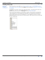
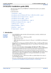
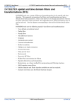
If you specify a scalar field as the Data field for gridding (see Input tab—Overview of
controls), and you do not specify a gradient field, INTREPID produces a grid of this
data. The illustration shows the Product drop-down list in the Output grid tab.
See also:
•
Gridding vector data
•
Gridding tensor data
•
Gridding of potential field data with observed gradients
Gridding vector data
Parent topic:
Using the
Gridding tool
You can specify a vector field (see "Compound data types" in INTREPID database, file
and data structures (R05)) as part of the input for gridding. You can specify it either
as the Data (see Input tab—Overview of controls) or as the gradient of the data (see
Gridding of potential field data with observed gradients).
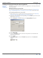
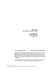
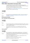
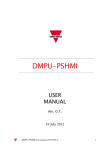
You can choose the following derived grid products. The illustration shows the
Product drop-down list in the Output grid tab (see Output Grid tab).
The default product is an Enhanced Signal grid. The tool will automatically choose
this option, if you use the Advanced button to add an Across gradient field, to
addition to the scalar signal field you have already chosen
To produce directly any of the other grid products listed below, you must add, via the
Advanced button, the appropriate sets of observed gradient fields.
With the object oriented data types now available in INTREPID, you can also use the
Single Field (intelligent) to add all vector components via the one field.
Library | Help | Top
© 2012 Intrepid Geophysics
| Back |
INTREPID User Manual
Library | Help | Top
Gridding (T22a)
6
| Back |
The option of having each gradient as a separate field in your database is provided to
preserve Canadian thinking, even though users may lose track of what processes
have been applied to each component in prior levelling and other data conditioning. .
Product
Details
Analytic signal
"Analytic signal filter (reference)" in INTREPID spectral domain operations
reference (R14)
Total horizontal
gradient
"Total horizontal derivative filter (reference)" in INTREPID spectral domain
operations reference (R14)
East horizontal
gradient
Horizontal derivative in the X direction. See "Generalised horizontal
derivative filter (reference)" in INTREPID spectral domain operations
reference (R14)
North horizontal
gradient
Horizontal derivative in the Y direction. See "Generalised horizontal
derivative filter (reference)" in INTREPID spectral domain operations
reference (R14)
Vertical gradient
"Vertical derivative filter (including fractional vertical derivative)
(reference)" in INTREPID spectral domain operations reference (R14)
Enhanced signal
Use this option if you are gridding a scalar field with gradient enhancement.
See Gridding of potential field data with observed gradients. This option is
not available if you specify only a vector field of components or gradients as
the main data for gridding.
Calculate diurnal
This is experimental - beta only
Transverse gradient
Transverse gradient is the Across gradient component
Longitude gradient
Longitudinal gradient is the Along gradient component (nothing to do with
geodetic longitudes)
Tilt angle (phase
map)
If you select Tilt angle, INTREPID uses the measured gradients to compute
atan(dZ/(total_horizontal_derivative))
It is similar to the analytic signal, except it has the character of the phase of
the signal. It varies from –90 to +90 degrees.
See also:
Library | Help | Top
•
Gridding scalar data
•
Gridding tensor data
•
Gridding of potential field data with observed gradients
© 2012 Intrepid Geophysics
| Back |
INTREPID User Manual
Library | Help | Top
Gridding (T22a)
7
| Back |
Gridding tensor data
Parent topic:
Using the
Gridding tool
You can specify a tensor field (see "Compound data types" in INTREPID database,
file and data structures (R05)) as the Data field for gridding (see Input tab—Overview
of controls).
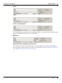
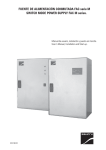
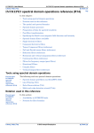
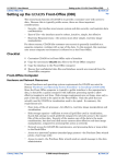
INTREPID can produce grids of the following products. The illustration shows the
Product drop-down list in the Output grid tab (see Output Grid tab).
To access this functionality, you must have created a tensor field in your database,
either on import, or via the dbedit tool. Generally, it is assumed you would have a
normal fully populated tensor, though there is some support for what we call the
Horizontal tensor, as observed by the Falcon system. This consists of the Txx-Tyy and
the Txy components.
Library | Help | Top
© 2012 Intrepid Geophysics
| Back |
INTREPID User Manual
Library | Help | Top
Gridding (T22a)
8
| Back |
You can choose to produce either a range of one-band scalar grids, or a full tensor
grid.
Product
Description
X,Y, Z, XY, YZ, ZX
Individual tensor components
Determinant - I1
First invariant of the tensor
Maximum, Middle,
Minimum Eigenvalue
Trace
Txx+Tyy+Tzz
Second invariant - I2
Ratio
see Peterson
Strike
atan(I2/I1)
Horizontal gradient
amplitude, direction
Curvature gradient
amplitude, direction
Grid
This is the default and it means create a Fully
interpolated 6 band BIL Ermapper grid, with each
component stacked band by band.
Note, geosoft does not support the notion of multi-band
geophysical grids, so do not use a “.grd” output grid
extension.
The most important innovation here is the use of the patented SLERP or Spherical
Linear interpolation method to allow a Full tensor interpolation. This is used for all of
the above options, and the calculation from the interpolated tensor is done at the
point of populating the cell with an output value.
See also:
Library | Help | Top
•
Gridding scalar data
•
Gridding vector data
•
Gridding of potential field data with observed gradients
© 2012 Intrepid Geophysics
| Back |
INTREPID User Manual
Library | Help | Top
Gridding (T22a)
9
| Back |
Gridding of potential field data with observed gradients
Parent topic:
Using the
Gridding tool
INTREPID can produce superior results if you supplement a scalar input field with
observed gradients.
Specifying gradients as a vector field
If you have a set of gradients stored in a field of vector type (see "Compound data
types" in INTREPID database, file and data structures (R05)), follow these steps.
>> To specify gradients as a vector field
Library | Help | Top
1
Ensure that you have specified and selected the input dataset (see Specifying
input and output files and Specifying several input datasets)
2
Specify the scalar field that you are gridding. Use the Data drop-down list in the
Input tab (see Input tab).
3
Choose Advanced. INTREPID displays the Input gradients dialog box.
4
Select Single Field.
5
Check the Gradients check box and select the gradient vector field from the
Gradients drop-down list.
6
Choose Close.
7
In the Output grid tab, from the Product drop-down list, select Enhanced
Signal.
© 2012 Intrepid Geophysics
| Back |
INTREPID User Manual
Library | Help | Top
Gridding (T22a)
10
| Back |
Specifying gradients as scalar components
If you have a set of gradients stored in a field of vector type (see "Compound data
types" in INTREPID database, file and data structures (R05)), follow these steps.
>> To specify gradients as a vector field
1
Ensure that you have specified and selected the input dataset (see Specifying
input and output files and Specifying several input datasets)
2
Specify the scalar field that you are gridding. Use the Data drop-down list in the
Input tab (see Input tab).
3
Choose Advanced. INTREPID displays the Input gradients dialog box.
4
Select Vector Field Group.
5
Check the Across, Along, Vertical check boxes according to the gradient fields
you have available.
6
For each gradient field, select a field from the corresponding drop-down list.
7
Choose Close.
8
In the Output grid tab, from the Product drop-down list, select Enhanced
Signal.
The minimum you must specify is one gradient or component of the field. The BiSpline method is choosen by default as the appropriate gridding method in this case.
It is recommended you not use any Grid refinements such as Laplace or MINQ as
these tend to negate the subtle contributions made by the observed gradients.
Library | Help | Top
© 2012 Intrepid Geophysics
| Back |
INTREPID User Manual
Library | Help | Top
Gridding (T22a)
11
| Back |
Enhanced potential field gridding—further notes
Parent topic:
Using the
Gridding tool
Sign convention for gradients from an aircraft
There is a local coordinate convention associated with acquisition. Since we are
dealing with vector components of the potential field, this convention must be
applied.
Assuming a moving platform for the acquisition vehicle such as an aeroplane:
•
The local Y positive or length component is tail to tip positive.
•
The cross component is left to right positive.
•
The vertical component is upwards positive.
Storage of gradients in the source dataset
The gridding algorithm accepts any or all of these vector gradients.
Before gridding, convert the differences between readings to nT/m. Divide the
difference by the distance between instruments
The local heading of the observation is also computed from the X, Y data and the
components are stored with each scalar field observation as vector components in the
E, N & Vertical projection system. That is, the observations are stored in a
normalized coordinate frame for internal use.
Opportunities for using this extra gradient data
•
Direct gridding of observed analytical signal
δT-⎞
⎛ δT
⎛ ----⎛ δT
------⎞
------⎞
⎝ δx ⎠ + ⎝ δy ⎠ + ⎝ δz ⎠
2
•
2
2
Direct gridding of observed total horizontal gradient, i.e.
⎛ δT
⎛ δT
------⎞
------⎞
⎝ δx ⎠ + ⎝ δy ⎠
2
2
•
Enhanced potential (TMI / Gravity) field grid, honouring observed gradients. (see
Enhanced potential field gridding—further notes)
•
For TMI, calculation of a short wavelength diurnal variation.
Akima splines
These are able to take an observed gradient along the spline direction. The line
direction gradient component is calculated for each observation point as required.
Minimum Curvature algorithm
Brigg's formulation is a first order finite difference approximation of La Place
condition (13 point kernel). This went to considerable trouble to remove any observed
horizontal gradient components.
This traditional formulation is revisited and redone as a second order finite difference
approximation (25 point kernel). Provision for observed gradients has also been
made.
Variable Density gridding
This alternative method also allows for observed gradients. No implementation,
supporting observed gradients, is available as yet.
Library | Help | Top
© 2012 Intrepid Geophysics
| Back |
INTREPID User Manual
Library | Help | Top
Gridding (T22a)
12
| Back |
The Gridding window
Parent topic:
Gridding
(T22a)
In this section:
•
Gridding window diagram
•
Changing display panel size
•
File menu options
•
Toolbar
•
Degrees display style
Gridding window diagram
Parent topic:
The Gridding
window
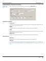
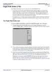
Here is a diagram of the Gridding window. The table below the diagram has more
information about the window elements.
Title bar
Process properties tabs
Menu bar
Toolbar
Task specifications
tree
Panel size adjustments
Data display panels
Apply button
The following table describes the screen elements.
Element
Purpose
Title bar
Shows the name of the tool.
Menu bar
Enables you to specify input datasets, output datesets, job files and
to view on-line help.
Toolbar
Buttons for specifying input and output datasets as well as units of
measurement for the gridding parameters.
Task specifications tree
A list of current set of specifications for the process and files
involved. To browse the tree use the + and - buttons to expand and
contract the sections.
Library | Help | Top
© 2012 Intrepid Geophysics
| Back |
INTREPID User Manual
Library | Help | Top
Gridding (T22a)
13
| Back |
Element
Purpose
Available filters list
A list of filters available. You can select filters from this list.
Process properties tabs
Properties of the currently selected Gridding process step
Apply button
Click this button to run the filtering process
Panel size adjustment
Use this to change the relative size of the data display area and the
lists and properties area
Changing display panel size
Parent topic:
The Gridding
window
Use the panel size control to change the relative size of the data display area and the
task control area.
>> To adjust the size of the data display and task specification areas
•
Drag the panel size control up or down OR
•
Click the up and down arrow icons
to make the data display or task
specification area occupy the whole window. Click the icons again to restore the
display so that both areas are visible.
File menu options
Parent topic:
The Gridding
window
See Specifying input and output files for more information.
Open Input Dataset Use this option to specify the input vector dataset.
Specify Output Dataset Use this option to specify the grid name. The output grid
may be a new or existing grid.
Load Options If you want to use an existing task specification file to specify the
Gridding process, use this menu option to specify the task specification file
required. INTREPID will load the file and use its contents to set all of the
parameters for the Gridding process. (See Task specification (.job) files in
Gridding for more information).
Save Options If you want to save the current Gridding file specifications and
parameter settings as an task specification file, use this menu option to specify
the filename and save the file. (See Task specification (.job) files in Gridding).
Exit Use this option to exit from the tool.
Library | Help | Top
© 2012 Intrepid Geophysics
| Back |
INTREPID User Manual
Library | Help | Top
Gridding (T22a)
14
| Back |
Toolbar
Parent topic:
The Gridding
window
The toolbar has the following buttons:
•
Specify input dataset
•
Specify output dataset
•
Load options
•
Save options
•
Degrees display selector
•
Help
Degrees display style
Parent topic:
The Gridding
window
For latitude and longitude data you can select degrees minutes seconds or decimal
degrees using the Degrees display selector button on the toolbar.
Specifying input and output files
Parent topic:
Gridding
(T22a)
INTREPID has controls for specifying the input and output datasets at logical places
in the tool, as well as some controls in the File menu and toolbar.
You can enter the path and ..DIR or .gdb file name of the datasets in the dataset
text boxes or browse using the [...] buttons.
If the grid is in the workng directory (see "Working directory" in Introduction to
INTREPID (R02)), there is no need to enter a path. Paths can be:
•
Relative to the working directory OR
•
Absolute
If you browse, INTREPID displays an Open or Save As dialog box. Use the directory
and file selector to locate the file you require. (See "Specifying input and output files"
in Introduction to INTREPID (R02) for information about specifying files).
In this section:
Library | Help | Top
•
Overview of input and output files
•
Aliases
© 2012 Intrepid Geophysics
| Back |
INTREPID User Manual
Library | Help | Top
Gridding (T22a)
15
| Back |
Overview of input and output files
Parent topic:
Specifying
input and
output files
This section is a summary of the input and output files, with cross references to the
instructions about them.
•
Input files
•
Input vector dataset
•
Aliases (aliases that this tool uses)
•
File menu options
•
Toolbar
•
Input tab
•
Subsection polygon - a many-sided polygon that can clip the area to be
gridded.
•
Input task specification file
•
•
File menu options
•
Toolbar
Grid for alignment of output grid
•
•
Output files
•
•
•
Library | Help | Top
Specifying grid alignment
Intermediate output files
•
Original data points from gridding methods—see Gridding Method tab
•
Coarse grids from variable density gridding method—see Gridding
Method—Variable density
•
Trend points from trend spline gridding method—see Gridding Method—
Trend Spline
•
Curvature grid from grid refinement—see Grid Refinement tab
Output task specification file
•
File menu options
•
Toolbar
Output grid
•
File menu options
•
Toolbar
•
Output Grid tab
© 2012 Intrepid Geophysics
| Back |
INTREPID User Manual
Library | Help | Top
Gridding (T22a)
16
| Back |
Aliases
Parent topic:
Specifying
input and
output files
If possible, INTREPID identifies the X, Y and line or point type fields from the
dataset aliases. Use the following aliases to identify appropriate fields:
Alias
Field
X
East–West geographic location coordinate
Y
North–South geographic location coordinate
LineType
Line type
PointType
Point quality
See "Vector dataset field aliases" in INTREPID database, file and data structures
(R05) for more information about aliases.
Input tab
Parent topic:
Gridding
(T22a)
The Input tab has controls for specifying input datasets and selecting fields to use in
the gridding.
In this section:
•
Input tab—Overview of controls
•
Specifying several input datasets
•
Identifying acquisition lines
•
Point quality
•
Nominal Bearing
See also Specifying input and output files.
Library | Help | Top
© 2012 Intrepid Geophysics
| Back |
INTREPID User Manual
Library | Help | Top
Gridding (T22a)
17
| Back |
Input tab—Overview of controls
Parent topic:
Input tab
This section gives an overview of the controls in the Input tab.
Add, Remove
Use these buttons to add or remove datasets from the Input dataset list. See
Specifying input and output files.
Properties
Choose Properties to view information about the selected input dataset (see
Specifying several input datasets). INTREPID displays the same information as the
Project Manager shows. See "Dataset preview and information display" in
INTREPID Project Manager (T02).
Input dataset
The Input dataset list shows the input datasets currently loaded for gridding. You
can select a dataset to view its information and select options for it. See Specifying
several input datasets.
X Field, Y Field
These drop-down lists show the selected geolocation fields of the selected input
dataset. INTREPID uses the dataset X and Y aliases to make default selections. You
can choose different geolocation fields from the lists. See Specifying several input
datasets.
Data
This drop-down list shows the data field selected for gridding in the selected input
dataset. You can select a different field from the list. See Specifying several input
datasets.
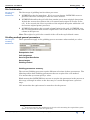
Advanced
Use Advanced to specify the gradient fields for gradient-enhanced gridding. See
Gridding of potential field data with observed gradients. The selected data type
appears immediately to the right of the Advanced button as a hint to the user. The
three possible types are illustrated below.
Library | Help | Top
© 2012 Intrepid Geophysics
| Back |
INTREPID User Manual
Library | Help | Top
Gridding (T22a)
18
| Back |
Scalar
Vector
Tensor “Coord System”
For multiband datasets the Advanced button changes to a band selector with the total
number of bands available shown to the right
Multiband
Acquisition lines identified by (check box)
(Line datasets only) Use this check box to specify whether you want to distinguish
acquisition lines from other lines in the selected dataset. See Identifying acquisition
lines and Specifying several input datasets.
Library | Help | Top
© 2012 Intrepid Geophysics
| Back |
INTREPID User Manual
Library | Help | Top
Gridding (T22a)
19
| Back |
Acquisition lines identified by (drop-down list)
(Line datasets only) Use this drop-down list to select the method of identifying
acquisition lines in the selected dataset. See Identifying acquisition lines and
Specifying several input datasets.
•
LineType Field (Line datasets only, acquisition lines identified by line type)
When this option is chosen a list box appears to the right allowing the user to
choose the appropriate Linetype field name. See Acquisition lines identified by a
line type field
•
Nominal bearing (Line datasets only, acquisition lines identifid by nominal
bearing)
Nominal bearing for acqusition lines. See Acquisition lines identified by Nominal
Bearing and Nominal Bearing.
•
Calculate.
Choose Calculate to automatically calculate the nominal bearing of the
dataset. See Acquisition lines identified by Nominal Bearing and Nominal
Bearing.
Heading correction
See Acquisition lines identified by Nominal Bearing and Nominal Bearing.
Specifying several input datasets
Parent topic:
Input tab
INTREPID can combine several datasets in one grid. The Input dataset list shows
the currently loaded input datasets.
The highlighted dataset is the currently selected dataset. INTREPID displays
information about this dataset in the Gridding window Input Tab. You can set input
options for this dataset.
To select a different input dataset, click it so that it is highlighted.
Identifying acquisition lines
Parent topic:
Input tab
This section is for line dataset gridding only. It is normal practice to use only
acquisition lines in the gridding process for line data.
Acquisition lines identified by a line type field
If there is a LineType alias or if you specify a line type field in response to a prompt,
INTREPID will use it to automatically exclude non-acquisition line data, processing
types 2 and 3 only See "Traverse line numbers and types" in INTREPID database, file
and data structures (R05) for a complete list of traverse line types and numbers.
If your dataset does not have a line type field but does have line numbers from which
you can derive a line type field, you can use the INTREPID Spreadsheet Editor
facility to create it. See "Create new field example—Line Type field" in Spreadsheet
Editor (T15)) for details about creating line type fields.
Library | Help | Top
© 2012 Intrepid Geophysics
| Back |
INTREPID User Manual
Library | Help | Top
Gridding (T22a)
20
| Back |
Acquisition lines identified by Nominal Bearing
If you do not specify a line type field, but you do specify a Nominal Bearing (estimate
of the strike (orientation) of the acquisition lines), INTREPID will identify the
traverse lines oriented within ±22½° of the Nominal Bearing as acquisition lines.
INTREPID uses the start and end points of a traverse line to calculate its strike.
If you want to use the Nominal Bearing setting to identify the acquisition lines, but
do not know their strike, INTREPID can calculate the average strike of the dataset
for you. See Nominal Bearing for instructions.
If you do not identify acquisition lines
If you deselect the tick box next to Acquisition lines identified by, INTREPID will
grid all traverse line data.
Point quality
Parent topic:
Input tab
This section is for point dataset gridding only. If there is a PointType alias or you
have specified a point type field, INTREPID will grid only those points for which the
point type = 1. If you have not specified a point type field, INTREPID will grid using
all points.
Nominal Bearing
Parent topic:
Input tab
This section is for line dataset gridding only. If you are gridding a field from a line
dataset using Bi-Cubic Spline , INTREPID needs to know the orientation of the
acquisition lines.
If you are gridding a field from a line dataset using Nearest Neighbours, Variable
Density or Box Filter, you can specify the orientation of the acquisition lines for the
purposes of quality control (i.e., rejecting lines that have different orientation) or to
specify rotation for the grid.
INTREPID compares the Nominal Bearing parameter with acquisition line
orientation. It uses the parameter for the following purposes:
Library | Help | Top
•
Determining the line direction for Bi-Cubic Spline and Trend Spline initial
gridding. See Gridding Method—Bi-Cubic Spline and Gridding Method—Trend
Spline below.
•
Identifying acquisition lines if there is no line type field. See Acquisition lines
identified by Nominal Bearing for more information.
•
Acquisition line quality control: INTREPID will only process traverse lines whose
direction is within ±22½° of the specified Nominal Bearing. This rule applies
irrespective of the acquisition line identification method (See Identifying
acquisition lines).
•
Specifying the required angle for a rotated grid if you have acquisition lines that
do not lie North–South or East–West. See Producing a rotated grid.
© 2012 Intrepid Geophysics
| Back |
INTREPID User Manual
Library | Help | Top
Gridding (T22a)
21
| Back |
To calculate the Nominal Bearing
Set the ‘Acquisition lines identified by’ to ‘Nominal Bearing’. Press the
Calculate button. INTREPID automatically calculates the bearing of the traverse
lines in the dataset for you, and writes the entry into the nominal bearing box.
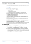
Subset tab
Parent topic:
Gridding
(T22a)
You can specify a region of interest for the Gridding process usinga polygon dataset.
INTREPID will only grid data within the region defined.
You can use the Subsection tool to define a polygon (See Subsections of datasets (T21)
for full instructions).
>> To specify a region of interest using a polygon dataset
Select the Polygon option on the Subset tab and specify the polygon dataset required
(see Specifying input and output files).
Library | Help | Top
© 2012 Intrepid Geophysics
| Back |
INTREPID User Manual
Library | Help | Top
Gridding (T22a)
22
| Back |
Preprocessing tab
Parent topic:
Gridding
(T22a)
You can choose one of the following
•
No preprocessing
•
A Convolution filter for smoothing the data (see Convolution preprocessing)
•
A Naudy filter for noise reduction (see Naudy preprocessing)
Select the process you require from the Preprocessing drop-down list on the
Preprocessing tab. The default process is None.
Convolution preprocessing
Parent topic:
Preprocessing
tab
1
If you have selected Convolve, specify the size of the convolution window in data
points, using the Window Size (data points) text box. See Convolution
preprocessing for an explanation.
This is a filter for smoothing the data. For each point, INTREPID will compare each
data value with neighbouring values along the line. If there are sudden changes,
INTREPID will adjust the current data value to make the changes smooth. You need
to specify the following:
Window Size (data points) Use this to specify the number of data points to be
compared around the point being adjusted. For example, if you set the window to
4, INTREPID will examine two points on each side of the current point to
calculate any adjustment. The default value of this parameter is 2.
Library | Help | Top
© 2012 Intrepid Geophysics
| Back |
INTREPID User Manual
Library | Help | Top
Gridding (T22a)
23
| Back |
Naudy preprocessing
Parent topic:
Preprocessing
tab
1
If you have chosen the Naudy filter, specify
•
The filter wavelength (in data points) using the Maximum Anomaly Width text
box
•
The filter tolerance (in data units) using the Tolerance text box,
•
Whether you want to produce the grid from the corrected data or from the data
rejected by the filter (i.e., the noise).
•
See Naudy preprocessing for an explanation.
This filter reduces noise in your data by detecting sudden changes or spikes that are
not characteristic of potential field data. You need to specify the following:
Maximum Anomaly Width (data points) Use this to specify the wavelength (in
data points) for the Naudy filter. The wavelength corresponds to the maximum
width of noise anomalies to be removed. INTREPID will remove anomalies
shorter than the wavelength you specify. The default value is 2.
Tolerance Use this to specify the filter tolerance (in Z units). The tolerance
corresponds to the minimum amplitude of suspected noise anomalies to be
removed. INTREPID will remove spikes with a amplitude higher than the
tolerance you specify. The default value 0.1 corresponds to 0.1nT, the current
documented accuracy of magnetometers. This ensures that INTREPID will only
remove noise, and not waste time attempting to smooth out the normal
fluctuations associated with the precision limits of the instrument.
Naudy Filter Options Select Use Corrected Data to produce the grid from the
corrected data. Select Use Rejected Data (Noise) to produce the grid from data
rejected by the filter (the 'noise').
Library | Help | Top
© 2012 Intrepid Geophysics
| Back |
INTREPID User Manual
Library | Help | Top
Gridding (T22a)
24
| Back |
Gridding Method tab
Parent topic:
Gridding
(T22a)
Gridding uses a mathematical interpolation and extrapolation process to calculate
values for the cells within the edge regions and also within enclosed gaps (fully
enclosed by but outside the edge regions). INTREPID ofers a number of methods for
this process. You can select and specify parameters for tehm in the Gridding Method
tab. In this section:
Grid initialisation
See Grid initialisation for a description of the initialisation process, common to all
gridding methods
General parameters
General parameters are common to all gridding methods. See Gridding method
general parameters.
Gridding method—Nearest neighbours
This is our recommended general purpose method. It works well for a wide range of
datasets. It uses two-point and three-point planar interpolation (triangulation). See
Gridding Method—Nearest Neighbours.
Gridding method—Bi-cubic spline
(Line datasets only) This method uses splining to assign cell centroid values. See
Gridding Method—Bi-Cubic Spline.
Gridding method—Box filter
This method is also successful with a wide range of datasets. It does not take account
of gradients in the process, and will tend to reduce the magnitude and size of features
in your results, compared with the other methods. It uses local averaging to assign
cell centroid values (assuming that the original data point is at the centroid of the
cell). If you use Nearest Neighbours or one of the Spline methods, INTREPID uses
the Box Filter to fill any gaps in the grid after your chosen process is complete. See
Gridding Method—Box Filter.
Gridding method—Variable density
This method was designed especially for gravity data acquired at variable sampling
densities, over the region you wish to create a gridded representation of the field. The
basic intent of the method, is to estimate various wavelength contents optimimally,
and to combine them into one, final grid that has the best assemblage of observed
wavelengths from the datasets provided.
To illustrate the above discussion further, take the case of regional gravity data being
collected on a regular grid at say 4 km spacings. Added to that, you may also have
observations taken along roads that criss-cross the area. Added to that again, you
may also have some small areas where detailed gravity observations have been
carried out on a grid at say 200m spacings.
See Gridding Method—Variable density.
Library | Help | Top
© 2012 Intrepid Geophysics
| Back |
INTREPID User Manual
Library | Help | Top
Gridding (T22a)
25
| Back |
Grid initialisation
Parent topic:
Gridding
Method tab
The first stage of gridding involves three processes.
1
INTREPID reads the input data. If it is a vector dataset, INTREPID creates a
grid data structure and aligns it with the source dataset.
2
INTREPID identifies the grid cells that contain one or more original data points.
It finds the nearest data point to the cell centroid and assigns its Z value to the
cell. It also records the 'exact'16 position of the original data point within the cell
for 'honour original points' processes.
3
INTREPID determines the row and column limits for the grid. INTREPID uses
the cell extrapolation limit and the original data cells at the ends of each row and
column in this process.
Note: The origin of a grid is the centroid of the cell in the top left hand corner.
Gridding method general parameters
Parent topic:
Gridding
Method tab
These parameters apply to the gridding process no matter what method you select.
Extrapolation limit
Cell Assignment
Save Original Data Points
Save triangles
Gridding method
Gridding parameters summary
The various Gridding processes require different selections of these parameters. The
following tables show Gridding parameters that are required for each method.
'Yes' means that you must specify a value.
Blank means that INTREPID does not use or require the parameter in the process at
this stage, although its effect on the data may be carried through from a previous
stage.
'ON' means that the option must be turned on for the process.
1. 16 To be more precise, the coordinates of the sub-cell containing the original data point.
(There are 128 x 128 sub-cells in a grid cell.)
Library | Help | Top
© 2012 Intrepid Geophysics
| Back |
INTREPID User Manual
Library | Help | Top
Gridding (T22a)
26
| Back |
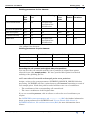
Gridding parameters for line datasets
Process
Grid
Cell
Size
Extrapolate
Cell
Nominal Bearing
Grid initialisation
yes
yes
if required for
acquisition line
identification
Nearest Neighbours
yes
yes
Bi-Cubic Spline
yes
yes
yes
Variable Density
yes
yes
no
Box Filter
yes
yes
if required for
acquisition line
identification
Rotate
Line
Data
Search
Radius
ON*
yes
Box
Iterations
yes
yes
* for 'oblique' line datasets
Gridding parameters for point datasets
Process
Grid Cell Size
Extrapolate Cell
Grid initialisation
yes
yes
Nearest Neighbours
yes
yes
Variable Density
yes
yes
Box Iterations
yes
Recording the cell centroid and original data point positions
You can save the cell centroids and the 'exact' positions of original data points
selected for use (the sample points). We have provided this option for technical
auditing of the gridding process.
>> To save the cell centroid and sample point exact positions
Assign a value to the system parameter INTREPID_HONOUR_ORIGINAL before
processing. INTREPID will save a point dataset called honour containing a record of
each sample point. Each data point recorded will have two sets of coordinates:
•
The coordinates of the corresponding cell centroid and
•
The 'exact' coordinates of the original data.
If you are examining honour, edit its aliases to select the set of coordinates you
require.
See INTREPID system parameters and install.cfg (R07) for further information
about system parameters in INTREPID and "Vector dataset field aliases" in
INTREPID database, file and data structures (R05) for more information about
aliases.
Library | Help | Top
© 2012 Intrepid Geophysics
| Back |
INTREPID User Manual
Library | Help | Top
Gridding (T22a)
27
| Back |
Recording the original data points used
You can save a record of the data points selected for use by this gridding process (the
sample points– selected because they were closest to the cell centroids).
>> To save the sample points used by Bi-Cubic Spline gridding
Assign a value to the system parameter INTREPID_FAST_POINTS before
processing. INTREPID will save the sample points for the process as a point dataset
called fast.
See INTREPID system parameters and install.cfg (R07) for further information
about system parameters in INTREPID.
Extrapolation limit
You need to specify cell extrapolation limits for a number of Gridding processes:
•
At the start of the gridding process INTREPID creates edge regions around the
original data cells. These regions will contain extrapolated / interpolated data.
The edge regions should ideally meet or overlap to satisfactorily fill gaps between
original data points (e.g., the gap between traverse lines, or the gap between
points of a point dataset). You need to specify appropriate cell extrapolation
limits for filling these gaps.
•
The image refinement processes also require an edge region containing data
around the whole grid. See Grid Refinement tab for details.
•
The data in the edge region around the outside of the grid may be discarded after
the image refinement processes. This process is called Clipping.
•
INTREPID interpolates values for all cells within regions fully enclosed by but
outside the edge regions. The Masking process deletes (sets to null) these regions
if required. Masking needs to know the extent of the edge regions. (See Setting
grid nulls for details).
>> To specify the cell extrapolation limit
Enter the limit (number of cells away from an original data point) into the
Extrapolate Cell parameter.
You should normally use an extrapolate cell value of at least 2. The default value is 2.
Cell Assignment
Use this to specify the assignment strategy of observations that fall into the same
initial grid cell. This applies only to grids that are created, not reprocessed.
The options are:
Library | Help | Top
•
Nearest Pick the nearest observation to the cell centroid
•
First Use the first observation encountered from the database
•
Last Use the last observation encountered from the database
•
Average Take a running average of all observations in the cell
•
Count
•
Minimum Take the smallest observation value as the cell value.
•
Maximum Take the largest observation value as the cell value.
Grid up the count of the number of observations in the grid.
© 2012 Intrepid Geophysics
| Back |
INTREPID User Manual
Library | Help | Top
Gridding (T22a)
28
| Back |
Gridding Method—Nearest Neighbours
Parent topic:
Gridding
Method tab
You can produce grids from line and point dataset fields using this method. It has
three stages.
1
Triangulation:
INTREPID makes a number of passes through the grid. It works along the rows
of the grid one by one starting alternately at the most Northerly row working
South and the most Southerly row working North.
For blank cells, INTREPID locates nearby original data cells and uses a
triangulation process to calculate values.
When it locates a neighbouring original data cell, it records this for the blank cell.
On the first pass through the grid, INTREPID searches for original data cells that
are immediate neighbours. On subsequent passes, INTREPID searches for
original data cells one cell further away each time from the blank cell. This
process is called shelling. INTREPID searches a minimum of 20 shells around
each cell.
When INTREPID has recorded three neighbouring original data cells for a blank
cell, it immediately locates all blank cells whose centroids lie within the triangle
formed by the three original data points.
INTREPID interpolates values for all cells within the triangle and marks all of
the cells in the triangle as processed. INTREPID uses an 'honour original data'
process for this interpolation, since it uses the actual positions of the original data
points rather than their cell centroids.
Note: The honour original data process described here uses the same information
but is otherwise not related to the honour original data options provided with
minimum curvature image refinement.
After completing a pass in which it is unable to perform any interpolation,
INTREPID moves to stage 2.
2
Linear interpolation:
INTREPID then passes through the grid examining all of the blank cells for
which it has found only two nearby original data points.
INTREPID interpolates values for all blank cells on the line between the two
original data points, once again using the position of the points rather than their
cell centroids.
3
Box filtering:
INTREPID passes through the grid using the Box Filter method (See Gridding
Method—Box Filter) and creates values for all remaining blank cells.
Library | Help | Top
© 2012 Intrepid Geophysics
| Back |
INTREPID User Manual
Library | Help | Top
Gridding (T22a)
29
| Back |
Tensor Interpolation using SLERP
A recent invention of Intrepid is to extend the nearest neighbour technique when you
are wanting to grid a Full tensor Data field. The Spherical Linear interpolation of the
rotations ( quaternions) part of the signal is automatically invoked at this stage. The
Eigenvalues of the tensor are interpolated using the above Nearest neighbour
methods for the current triangle.
In this way, an estimate of the curvature gradients of the Potential field can be made
smoothly at any point in the near distance to actual observations.
As this constitutes a major extension to the concept of gradient enhanced gridding,
the ability to grid to a finer cell size is also present. Studies show that instead of the
normal 4 cells between flight lines, up to 8 cells can be supported without significant
aliasing. The testing with the Full Magnetic tensor has not been as extensive, as with
the Full Gravity gradient tensor.
Gridding Method—Bi-Cubic Spline
Parent topic:
Gridding
Method tab
This section is for line dataset gridding only. You can produce grids from line dataset
fields using this method, which is sometimes called 'fast grid'.
Note: The jGridding tool is able to use tiling with this method.
Also note, with lines at an angle, it is normal to produce a rotated grid, with either
rows or columns in the same orientation as the acquisition lines.
While using this method of calculating values for interpolated cells, INTREPID
creates a located line structure that is closely related to the columns and rows of the
grid being created. There are three stages of gridding with this method.
1
Pass along acquisition lines
INTREPID uses spline curves along the acquisition lines to calculate values that
will correspond to all grid cells.
2
Pass across acquisition lines
In the second pass INTREPID examines each column or row of the located line
structure perpendicular to the acquisition line direction. It notes the values
obtained in the first pass (nodes) and uses them to calculate a spline curve
perpendicular to the acquisition line direction. It uses the spline curve to
calculate values in between the traverse lines. The following diagram illustrates
the process.
3
Box filtering
INTREPID passes through the grid using the Box Filter method (See Gridding
Method—Box Filter) and creates values for any remaining blank cells.
Library | Help | Top
© 2012 Intrepid Geophysics
| Back |
INTREPID User Manual
Library | Help | Top
Gridding (T22a)
30
| Back |
Bi-Cubic Spline parameters
Minimum, Maximum Scan Distance When interpolating a value for a group of
cells during the second pass of the Bi-Cubic Spline process, INTREPID searches
in both directions for nodes so that it can calculate a spline curve. It requires two
nodes on each side of the cells. This parameter specifies a distance limit for this
search. If INTREPID cannot find the nodes within this distance, it will not
interpolate the cells.
Specify the Search Radius (in distance units) in the corresponding text box. We
recommend a Search Radius larger than twice the line spacing, or 10 times the
cell size (The recommended number of cells from one line to the next is 4).
Note: If your dataset is geodetic (latitude and longitude) you need to specify the
Search Radius in degrees.
Nominal Bearing, Rotate Line Data, Spline Type
Spline Gradient Signal-Noise Blending.
Spline Gradient Noise Level.
Gridding Method—Trend Spline
Note: This method is retired and no longer available!!
Parent topic:
Gridding
Method tab
This section is for line dataset gridding only. You can produce grids from line dataset
fields using this method. This method is retired and no longer available!! Sorry, but it
was not worth the effort of keeping it going, and also, with the new intelligent data
type fields, quite tricky to support. For instance, how do you define a trend for a
tensor field? (DJF Dec. 2007)
Trend spline uses Bi-Cubic Spline gridding but includes a preliminary process which
examines groups of lines together to find directional trends. Using this information
in the gridding process can enhance the appearance of anomalies that lie at oblique
angles to the traverse lines.
Note: We recommend that you only use this method with surveys that have regularly
spaced lines.
Library | Help | Top
© 2012 Intrepid Geophysics
| Back |
INTREPID User Manual
Library | Help | Top
Gridding (T22a)
31
| Back |
The Trend Spline direction finding process involves two basic steps
1
INTREPID examines changes in all directions along groups of lines and calculates
a trend direction for each data point (the direction in which there is the least
change).
2
INTREPID uses this data to create sets of additional data points between the
acquisition lines.
___
After the direction process, INTREPID creates the grid using the Bi-Cubic Spline
method (See Gridding Method—Bi-Cubic Spline)
___
The process finds maxima and minima in adjacent lines and associates them.
For full details of these process see articles by Brindt and Hauska (1985)17 and
Fitzgerald, Yassi and Dart (1997)28.
It is possible to 'tune' Trend Spline gridding to accept or reject solutions based upon
reliability of data in one direction versus another. If this capability is of interest to
you, please contact our technical support service.
Trend spline parameters
Minimum, Maximum Scan Distance See Gridding Method—Bi-Cubic Spline for
an explanation of this parameter.
Nominal Bearing See Gridding Method—Bi-Cubic Spline for comments about this
parameter.
Rotate Line Data See Gridding Method—Bi-Cubic Spline for comments about this
parameter.
Spline Type See Gridding Method—Bi-Cubic Spline for an explanation of this
parameter.
(Trend Variance Factor)
The trend variance factor is the minimum level for significance of local variations.
The number of trend points generated is very sensitive to the value of this
parameter. Its default value is 1 (Z unit) You can change the value of the trend
variance factor if you are using a task specification file for your gridding process.
Edit the task specification (.job) file, changing the value in the
Trend_Variance_Factor = line according to your requirements, e.g.,
Trend_Variance_Factor = 2. See Task specification (.job) files in Gridding
for further information.Recording the additional trend points
Trend picker window size INTREPID applies a high pass filter to the data before
examining trends. This filter is in the form of a moving average. INTREPID uses
the residual values from this moving average filter. You can specify the size (in
grid cells) of the window for the filter.
Minimum Anomaly INTREPID will not process maxima or minima with amplitude
less than the value3 you specify here
1.7 Brindt, L. and Hauska, H., 1985, Direction dependent interpolation of aeromagnetic
data Eleventh International Symposium on Machine Processing of Remotely Sensed Data,
Purdue University, Indiana, USA.
2.8Fitzgerald, D., Yassi, N. and Dart, P., 1997, A case study on geophysical gridding
techniques: INTREPID perspective: Exploration Geophysics, 28, 1–
Library | Help | Top
© 2012 Intrepid Geophysics
| Back |
INTREPID User Manual
Library | Help | Top
Gridding (T22a)
32
| Back |
Minimum Search Angle INTREPID will not record trends at angles closer to the
line direction than the angle you specify here. Trends close to the line direction
are too hard to follow using the trend gridding method because of the oblique
distances between the lines. Trends in the line direction do not need
enhancement, in any case.
Save Trend Points Dataset To save the additional trend points, turn on this check
box and specify the name for the additional trend points dataset.
This option replaces the use of the INTREPID_TREND_POINTS system
parameter and the procedure described in (Trend Variance Factor).
You can save a record of the additional data points created between the acquisition
lines (the additional trend points).
>> To save the additional trend points
Assign a value to the system parameter INTREPID_TREND_POINTS before
processing. INTREPID will save the additional trend points as a point dataset called
trend.
See INTREPID system parameters and install.cfg (R07) for further information
about system parameters in INTREPID.
Process reports for the Trend Spline method
You can inspect a report of the aspect ratio between line spacing and cell size during
the gridding process. Under Unix this appears in the background window. Under
Windows it is written to an ntout report file. See "Diagnostic reporting options" in
Configuring and using INTREPID (R04) for more information.
3. in Z units, for example, nT
Library | Help | Top
© 2012 Intrepid Geophysics
| Back |
INTREPID User Manual
Library | Help | Top
Gridding (T22a)
33
| Back |
Gridding Method—Box Filter
Parent topic:
Gridding
Method tab
You can produce grids from line and point dataset fields using this method. The Box
filter progressively examines each empty cell in the grid in relation to its immediate
neighbours and calculates a value for it based on an average value of its neighbours.
The Box Filter process repeats until all cells have a value or until it has completed
the maximum number of iterations you have specified.
The Box Filter assumes that the original data points are at the cell centroids. It does
not take account of the actual position of data points within the cell (i.e., it has no
'honour original points' process) and therefor may not be as accurate as other
methods.
Box Filter as a finishing process for other methods
If you use Nearest Neighbours or one of the Spline initial gridding methods,
INTREPID uses the Box Filter after the process to fill any remaining gaps in the grid.
Box Filter parameters
Box iterations You can use this text box to specify the maximum number of Box
filter iterations you want INTREPID to perform before moving to the image
refinement stage.
You do not need to specify Box Iterations if Box Filter is operating only as a final
stage of another initial gridding method.
Library | Help | Top
© 2012 Intrepid Geophysics
| Back |
INTREPID User Manual
Library | Help | Top
Gridding (T22a)
34
| Back |
Gridding Method—Variable density
Parent topic:
Gridding
Method tab
This method was designed especially for gravity data acquired at variable sampling
densities, over the region you wish to create a gridded representation of the field. The
basic intent of the method, is to estimate various wavelength contents optimimally,
and to combine them into one, final grid that has the best assemblage of observed
wavelengths from the datasets provided.
To illustrate the above discussion further, take the case of regional gravity data being
collected on a regular grid at say 4 km spacings. Added to that, you may also have
observations taken along roads that criss-cross the area. Added to that again, you
may also have some small areas where detailed gravity observations have been
carried out on a grid at say 200m spacings.
The method is implemented using a multi-grid approach. Working back from the
required final cell size, a series of 2 or 3 extra, coarser grids are produced, using the
Nearest neighbour technology.
These coarse grids are designed to properly capture the longer wavelength data, at an
appropriate cell size. eg for 4 km data, a 1 km cell size would not be aliased, and
properly represents this aspect of the signal.
The final cell size might well be 50m, with the aim of capturing the higher frequency,
shorter-wavelength field information from the 200m data.
To progress down to this finer cell size, a resampling from the coarsest grid to the
next intermediate grid is made, lets say 200m cell size. This intermediate grid is then
immediately “weeded” around those cells that fall near an observation of gravity,
opening up the gridded representaion of the field for further interpolation and local
estimation.
Finally, in the scenario from above, a jump to the 50 m cell size is made.
Library | Help | Top
© 2012 Intrepid Geophysics
| Back |
INTREPID User Manual
Library | Help | Top
Gridding (T22a)
35
| Back |
Notes about implementation detail
1.Low prime number ratios between cell sizes are used to minimise resampling
artifacts. You are asked to choose from a limited set of factors that range through
combinations of 2,3,4,5,7 and 11.
2.Weeding goes out around any observation a distance of 2 cells sizes at each stage.
3. At least 10 iterations of Minimum Curvature are applied to the coarse grids, to
ensure a good representation of the smoothed long-wave content is created and can be
handed on to the next stage.
4. Persistence of longer wavelength features can be clearly seen in the output grids,
following application of this method.
5. The method was devised at Geoscience Australia, by several workers, including
Alice Murray, in an effort to create a best possible gravity grid from extremely
irregularly sampled field data.
Pass list
Reduction factor
This is the list of prime number factors to reduce from a coarse cell size to the final
cell size using a multi-grid approach.
Cell Size
Final cell size required
Coarse Iterations
You can influence the number of iterations of coarse MIN. Curvature smoothing.
Save Coarse Grids
Good idea to have a look at these, to confirm you can see the longer wavelengths.
Weight Type
The normal option here is Unity. This means give each point/observation equal
weighting during the gridding process. The other options are Magnitude - give more
weighting to the observation with the largest positive value eg Depth, and Square
Root - give a weighting to the Square Root of the magnitude of the signal during 3
point interpolations.
Library | Help | Top
© 2012 Intrepid Geophysics
| Back |
INTREPID User Manual
Library | Help | Top
Gridding (T22a)
36
| Back |
Grid Refinement tab
Parent topic:
Gridding
(T22a)
After the initial gridding process, INTREPID can perform LaPlace convolution and
Minimum Curvature grid refinement, then restore interpolated grid cells to null as
required.
If you are refining an existing grid, INTREPID can perform LaPlace convolution and
Minimum Curvature Smoothing refinement. The Minimum Curvature process will
not use the honour originals method in this case, since no original data is available.
<>
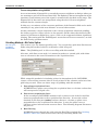
Specify grid refinement processes in the Grid Refinement tab.
In this section:
Library | Help | Top
•
LaPlace iterations
•
Minimum Curvature
•
Setting grid nulls
© 2012 Intrepid Geophysics
| Back |
INTREPID User Manual
Library | Help | Top
Gridding (T22a)
37
| Back |
LaPlace iterations
Parent topic:
Grid
Refinement tab
This is a heavy smoothing convolution filter that INTREPID applies to all initial grid
estimates. It leaves the original points alone. The process improves the condition of
the grid for the Minimum Curvature process. If you perform LaPlace convolution,
Minimum Curvature will require fewer iterations to achieve a satisfactory result.
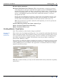
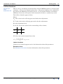
The LaPlace formula appears below.
Where
Z0 is the value in the cell being processed before the adjustment,
Z01 is the value in the cell being processed after the adjustment,
R is the relaxation factor,
Z1, Z2, Z3, Z4 are the values in the surrounding cells as shown,
Z1
Z2
Z0
Z3
Z4
If Z0 does not contain original data, then
Z1 + Z2 + Z3 + Z4
1
Z 0 = ⎛ -----------------------------------------– Z 0⎞ × R + Z 0
⎝
⎠
4
Laplace iterations
Contact our technical support service for information about this parameter.
Relaxation factor
See Minimum Curvature for more information about this parameter.
Library | Help | Top
© 2012 Intrepid Geophysics
| Back |
INTREPID User Manual
Library | Help | Top
Gridding (T22a)
38
| Back |
Minimum Curvature
Parent topic:
Grid
Refinement tab
The Minimum Curvature method progressively examines each interpolated cell in the
grid in relation to its immediate neighbours and changes its value based on the value
of the neighbours.
The aim of the minimum curvature method is to produce a smooth surface of grid
values. Working in both directions, it adjusts cell values using a second derivative
calculation based on the differences between the values of the adjacent cells. It does
not modify the original data points.
A note about this method and the new Spherical Linear Interpolation method for
Full tensor data.
These two methods are largely incompatible with each other. Minimum Curvature is
designed to calculate from a scalar measure of a potential field the curvature
gradients, in particular Txx,Tyy, Tzz and to use a finite difference method to force the
residual of the Trace (Txx+Tyy+Tzz) to zero in all parts of the grid. A Full Tensor
grid already contains these curvature gradients and so the above ideas no longer
hold. An alternative formulation based on forcing incremental derivatives of the
horizontal components into a compliant relationship is in preparation and will be
released in Intrepid shortly.
INTREPID uses a relaxation factor to accelerate the interpolation process. As
INTREPID calculates a new value for each interpolated cell, it multiplies the
difference between the old and adjusted value by the relaxation factor. The default
value of the relaxation factor is 1.375.
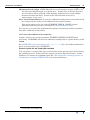
Where
Z0 is the value in the cell being processed before the Minimum Curvature adjustment,
ZA is the adjusted value in the cell after the Minimum Curvature process has been
applied,
R is the relaxation factor,
Z1 is the new value in the cell being processed after the minimum curvature process
and relaxation factor adjustment have been applied,
If Z0 does not contain original data, then
Z1 = ( ZA – Z0 ) × R + Z0
INTREPID will repeat the process until it has completed the number of iterations you
specify in the Maximum Iterations text box, or the maximum residual change for all
cells is less than the value you specified in the Maximum Residual text box,
whichever occurs first.
Library | Help | Top
© 2012 Intrepid Geophysics
| Back |
INTREPID User Manual
Library | Help | Top
Gridding (T22a)
39
| Back |
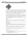
INTREPID normally uses a kernel of cells immediately surrounding the target cell as
comparison values in the Minimum Curvature process, as shown below.
The Minimum Curvature process can use an 'honour original data' system if required.
If you choose this method, INTREPID allows for the actual position of the original
data point in an original data cell (rather than the cell centroid) when calculating the
weight (influence) of the cell in an adjustment of a neighbouring cell. If you are using
the Gridding tool to enhance an existing grid, the grid will have no link with its
original data, and therefore INTREPID cannot use any honour originals method. See
below for additional explanation of the honour originals process.
At the end of the Minimum Curvature process, INTREPID can perform several
further passes through the grid where it adjusts original data cells values in the same
way as it has been adjusting interpolated cells. This process is called smoothing, and
has the effect of further smoothing the grid near original data cells.
If you are using the Gridding tool to enhance an existing grid, INTREPID will only
perform the Minimum Curvature process in Smoothing mode, since the original data
can not be distinguished.
Iterations
Use this spinner to specify the maximum number of times that INTREPID may scan
through the grid (number of iterations) during the minimum curvature process.
Kernel size
Use this drop-down list to specify the kernel size for the minimum curvature process.
Maximum Residual
Each time INTREPID scans the grid in its attempt to smooth the grid, it may cause a
change in the value of each interpolated cell. As it completes each progressive scan,
the change in each cell becomes smaller—the interpolated values are becoming
'settled'.
Use this text box to specify the stage at which you consider that the interpolated
values are sufficiently 'settled' (subsequent residual changes will be ignored).
Specify the Maximum Residual in the same units as your signal data.
If you are gridding magnetic data we recommend a value of 0.1nT to produce the best
print quality.
The Minimum Curvature process will stop when:
Library | Help | Top
•
Every cell has changed during the last scan by less than the value that you specify
(the maximum residual change), or
•
The maximum iterations have been performed.
© 2012 Intrepid Geophysics
| Back |
INTREPID User Manual
Library | Help | Top
Gridding (T22a)
40
| Back |
Relaxation factor
See above in this section for an explanation of the function of the relaxation factor.
(Task files) You can change the value of the relaxation factor if you are using a task
specification (.job) file for your gridding process. Edit the .job file, changing the
value in the Relaxation_Factor = line according to your requirements.
Example: Relaxation_Factor = 1.325. See Task specification (.job) files in
Gridding for information about batch mode.
Tension
Contact our technical support service for information about this parameter.
Honour Original Data
If you turn off Honour Original Data, INTREPID will assume that the original data
points are located at the centroids of all original data cells, and calculate the same
weight (influence) for the cell in all directions.
If you turn on Honour Original Data, INTREPID will allow for the actual position of
the original data point in an original data cell (rather than the cell centroid) when
calculating the weight (influence) of the cell in an adjustment of a neighbouring cell.
This can improve the accuracy of the image refinement process. An original data
point can have up to 128 x 128 different positions in a cell.
If you are using the Gridding tool to enhance an existing grid, original data is not
available and INTREPID will automatically turn Honour Original Data off.
The Honour Original Data method has two variants: 1 cell and 2 cell. See the section
immediately following for an explanation.
Note: The honour original data process described here uses the same information
but is otherwise independent of the honour original data process used in Nearest
Neighbours initial gridding (See Gridding Method—Nearest Neighbours).
Honour Original Data—1 or 2 cell
Choose the option button according to your requirements. The default option is 2 cell.
For 1 cell Honour Original Data, INTREPID simply calculates the weight (influence)
of each original data cell on neighbouring cells based on the location of the original
data point rather than the cell centroid, as explained above.
For 2 cell Honour Original Data, for each original data cell, INTREPID
1
Locates the quadrant of the original data cell in which the original data point lies;
2
Treats the 3 cells surrounding this quadrant as original data cells;
3
Locates the nearest original data points to the respective centroids of the 3 cells;
4
For each of the 3 cells, uses the value of its chosen data point and its position to
calculate the weight (influence) of the cell for adjusting neighbouring cells.
Smoothing
If you turn on Smoothing, after INTREPID has completed the Minimum Curvature
process, it will perform several further Minimum Curvature passes through the grid.
During these passes it will adjust original data cell values in the same way as it has
been adjusting interpolated cell values. This has the effect of further smoothing the
grid.
Library | Help | Top
© 2012 Intrepid Geophysics
| Back |
INTREPID User Manual
Library | Help | Top
Gridding (T22a)
41
| Back |
Smoothing Iterations
Use this spin box to specify the number of smoothing iterations to perform.
Save curvature grid
Contact our technical support service for information about this parameter.
Setting grid nulls
Parent topic:
Grid
Refinement tab
Depending on the density of your original data, the cell size, and the value of the
Extrapolate Cell parameter, INTREPID will fill gaps in the grid during the gridding
process.
You may, on one hand, require a grid with no undefined regions, and require the
Gridding tool to fill all gaps as best it can by interpolation.
On the other hand, you may
•
Have one or more regions which have no observed data at all, and for which
interpolated data would be meaningless, or
•
Require that the grid contain only data that is close to original data points.
INTREPID uses a masking process to make the grid conform to these requirements.
It sets to null all interpolated cells that are too far from an original data cell.
INTREPID can use the value of the Extrapolate Cell parameter as the limit for
retaining or removing interpolated cells. For example, if Extrapolate Cell=2, then it
can set to null all interpolated cells that are more than 2 cells away from an original
data cell.
Internal—fill holes
If you want INTREPID to fill all holes, check this check box. INTREPID fills all holes
regardless of:
•
The value of Extrapolate Cell
•
Your selected Setting grid nulls option for Edges
Edges
Use this drop-down list to specify masking for the edges of the grid.
Setting
Descriptions
Original data limits
INTREPID sets to null all extrapolated edge cells
(non-original data cells)
Extrapolation limits
INTREPID sets to null all extrapolated edge cells that
are further from an original data cell than the
Extrapolate Cell value
Strict Extrapolate cells
A new more robust version of Extrapolation limits
which uses a moving window and is sensitive to
internal holes; also better for random point data of
variable spacing. Three further tuning options are
available for this method in batch mode (see below).
•
Strict Extrapolate Cells tuning options (batch only)
•
Library | Help | Top
Minimum Quadrants
© 2012 Intrepid Geophysics
| Back |
INTREPID User Manual
Library | Help | Top
Gridding (T22a)
42
| Back |
•
•
Minimum Within
•
•
Only keep an interpolated cell if the minimum number of quadrants were
populated with original data (default is 0).
Only keep an interpolated cell if the minimum number of original data
cells are within the extrapolate limit (default is 1).
Quadrant Extension
•
Make quadrants larger so that they overlap (defaults is 0)
Example job file syntax:
INTREPID_QUADRANT_EXTENSION = 4
INTREPID_MINIMUM_QUADRANTS = 2
INTREPID_MINIMUM_WITHIN = 8
Process Begin
Name = GriddingPro
Parameters Begin
Input_Datasets_Begin
Input_Dataset_1 Begin
Input_Daataset = $(dataset)..DIR
Input_X = lon
Input_Y = lat
.....
.....
Output Grid tab
Parent topic:
Gridding
(T22a)
Library | Help | Top
The Output tab has controls for specifying the output dataset, its content, datum and
projection, rotation, alignment and constraints.
In this section:
•
Output grid tab—Overview of controls
•
Producing a rotated grid
•
Note: Calculation of the row and column limits
•
Specifying grid alignment
•
Specifying the cell size
•
Note: Calculation of the row and column limits
© 2012 Intrepid Geophysics
| Back |
INTREPID User Manual
Library | Help | Top
Gridding (T22a)
43
| Back |
Output grid tab—Overview of controls
Parent topic:
Output Grid
tab
This section gives an overview of the controls in the Output grid tab.
Output File Options
Output grid
Use this text box or browse button to enter the name and path of the output grid. See
Specifying input and output files.
Bands
Use this spin box to specify the number of bands for the output dataset.
Band
(For datasets with more than one band) Specify the number of the band that you want
this gridding operation to create.
Band Name
Set the output grid band name. It defaults to the input Data field name.
Data Options
Null Value
Set the value to be used to represent a null value in the output grid.
DataType
Use this drop-down list to specify the precision of the grid that you are creating. See
"Data Types in INTREPID datasets" in INTREPID database, file and data structures
(R05).
Library | Help | Top
© 2012 Intrepid Geophysics
| Back |
INTREPID User Manual
Library | Help | Top
Gridding (T22a)
44
| Back |
Product
Use this drop-down list to specify the data product that you want to grid.
If you have specified a scalar field with no gradient enhancement, INTREPID
disables this list, because it simply grids the data in the data field. See Gridding
scalar data.
(If you have specified a vector or tensor field for gridding, or gradient fields (separate
components or vector) to enhance a scalar field) Use this drop-down list to select the
product for INTREPID to grid. Each type of input data has its own set of entries in
this list. For details, see:
•
Gridding vector data
•
Gridding tensor data
•
Gridding of potential field data with observed gradients (same options as
Gridding vector data)
Rotation
Use this spin box to specify the number of degrees of rotation for the output grid. See
Producing a rotated grid for details.
Grid Dimensions (centroids)
Origin (TL), Bottom Right
Use these spin boxes to specify the X and Y coordinates of the top left (origin) and
bottom right points of the output grid. If you set these values, INTREPID
automatically adjusts Extents and (number of) Cells.
Note that the coordinates defined are for the centre of the cells at the top left and
bottom right of the output grid. They do not define the outside bounding box of the
grid ie they are half a cell inside the box limits.
Extents
Use these spin boxes to specify the size in distance units of the grid in the X and Y
directions. If you set these values, INTREPID automatically adjusts Bottom Right
and (number of) Cells.
Cells
Use these spin boxes to specify the number of cells in the grid in the X and Y
directions. If you set these values, INTREPID automatically adjusts Bottom Right
and Extents.
Cell size
Use these spin boxes to specify the size in distance units of the cells in the grid in the
X and Y directions. If you set these values, INTREPID automatically adjusts Bottom
Right, Extents and (number of) Cells. You can specify equal size in both directions
using the x=y checkbox. See Specifying the cell size for more information.
If you click and type the required cell size into these boxes rather than use the
spinners then you must hit return before INTREPID will update the Bottom Right,
Extents and (number of) Cells.
x=y
Use this check box to specify whether cells are of the same size in both directions. If
you check this box, INTREPID uses the X Cell size for both cell dimensions.
Library | Help | Top
© 2012 Intrepid Geophysics
| Back |
INTREPID User Manual
Library | Help | Top
Gridding (T22a)
45
| Back |
Reset extents
Choose Reset extents to automatically recalculate the default extents for the output
grid.
Producing a rotated grid
Parent topic:
Output Grid
tab
You may be gridding a field from a line dataset with 'oblique' acquisition lines (that
do not lie North–South or East–West). The survey may have been created like this,
for example, so that the data is perpendicular to the strike of a feature of interest.
You may want to produce a rotated grid from 'oblique' data with its rows or columns
in the direction of the acquisition lines. After producing the grid you can rotate it so
that the rows lie East–West. See "Rotating a grid" in Grid Operations (T25) for
instructions.
If you are gridding an 'oblique' line dataset using the Bi-Cubic Spline or Trend Spline
method in the gridding process, you must produce a rotated grid.
With the Nearest Neighbours and Box Filter methods producing a rotated grid from
an 'oblique' line dataset is not compulsory. (See Gridding Method tab.)
Specifying grid alignment
Parent topic:
Output Grid
tab
Note: This feature is not supported in Intrepid V4.2.3.
Default
Same as another grid
Use the text box or browse button to enter the name and path of the control grid. See
Specifying input and output files.
Aligned with (another) grid
Use the text box or browse button to enter the name and path of the control grid. See
Specifying input and output files.
Aligned with coordinates (X, Y)
Specify the coordinates of the alignment point in the X and Y text boxes, using
distance units of the output grid.
Library | Help | Top
© 2012 Intrepid Geophysics
| Back |
INTREPID User Manual
Library | Help | Top
Gridding (T22a)
46
| Back |
Specifying the cell size
Parent topic:
Output Grid
tab
Use the Cell Size spin boxes and the x=y checkbox to specify the size of one grid cell in
the distance units of the dataset.
Setting an appropriate cell size is a balance between having a fine 'mesh' grid and
having gaps or excessive interpolation between cells which may lead to inaccuracies.
If you are gridding from a line dataset we recommend a cell size not greater than one
quarter to one fifth of the line spacing.
If you have a smaller cell size than recommended, we suggest that you increase the
cell extrapolation limit (See Extrapolation limit for details).
Note: If your dataset is geodetic (latitude and longitude) you need to specify the grid
cell size in degrees.
Library | Help | Top
© 2012 Intrepid Geophysics
| Back |
INTREPID User Manual
Library | Help | Top
Gridding (T22a)
47
| Back |
Note: Calculation of the row and column limits
The row and column limits of the grid are lists of the locations of the outermost cells
in each row and column which are to contain data.
In this discussion we will use the following notation
EC
= value of the Extrapolate Cell parameter
LO
= cell position of the outermost original data cell at the current end of
the current row or column
LE
= cell position EC cells further out than LO for the current end of the
current row or column
{LE±EC}
= the set of LE cell positions for the current end of the EC rows or
columns before and EC rows/columns after the current row/column
Max{LE±EC}
= the outermost LE position in the LE±EC set
L
= row or column limit finally recorded
INTREPID calculates the row and column limits as follows.
For the left hand end of each row, INTREPID
1
Locates the leftmost original data cell (LO);
2
Locates the cell EC cells further left than LO (LE);
3
Locates the LE positions for the previous EC rows and the next EC rows {LE±EC};
4
Finds the leftmost cell of the set LE±EC ( Max{LE±EC} )
5
Records the X coordinate of Max{LE±EC} as the X coordinate of the left hand row
limit for the current row (X coordinate of L). (The Y coordinate is, of course, the
row number.)
INTREPID performs this process correspondingly for the right end of each row and
for each end of the columns.
The overall effect of this process is to
•
Produce a 'square ended' effect for groups of rows and columns, and
•
Fill out rows/columns with 'inadequate' original data cells to a common grid edge.
Apply
Parent topic:
Gridding
(T22a)
Library | Help | Top
When you choose Apply INTREPID carries out the Gridding process that you have
specified.
© 2012 Intrepid Geophysics
| Back |
INTREPID User Manual
Library | Help | Top
Gridding (T22a)
48
| Back |
Task specification (.job) files in Gridding
Parent topic:
Gridding
(T22a)
This section gives an overview, example and describes the syntax of Gridding task
specification files.
A Gridding task specification (.job) file specifies:
•
Input and output grid filenames
•
Griddng parameters
Notes
You can modify the following operations or parameters only by editing a task
specification file:
•
You can modify the relaxation factor in the minimum curvature process (See
Minimum Curvature for details). Change the value in the
Relaxation_Factor = line according to your requirements, e.g.,
Relaxation_Factor = 1.325.
•
You can modify the Trend_Variance_Factor. See Gridding Method—Trend
Spline for details. Note: The Trend Spline method is no longer supported in the
gridding tool.
Finding out more about task files and batch processing mode
Use the following references:
Introduction to INTREPID auxiliary files,
such as task files
"INTREPID Auxiliary files" in INTREPID database,
file and data structures (R05)
Structure, syntax and use of INTREPID task
files
INTREPID task specification (.job) files (R06)
Running INTREPID in batch processing
mode
"How to start INTREPID—Overview" in Introduction
to INTREPID (R02)
Main block structure of a Gridding task file
The following table shows the main block structure of a Gridding task file. See for
more details.
Block definition
Contents
Process Begin
Task file outer block
—Tool name and date stamp
—Parameters block
——Filenames
——Parameters
—End
End
...
Parameters Begin
...
...
Parameters End
Process End
Library | Help | Top
© 2012 Intrepid Geophysics
| Back |
INTREPID User Manual
Library | Help | Top
Gridding (T22a)
49
| Back |
Sample Gridding task specification (.job) file
Here is an example of a Gridding task.
Process Begin
Name = GriddingPro
Parameters Begin
Grid_Refinement Begin
Fill_Holes= yes
Edge_Clipping= Extrapolation_limits
Laplace_Iterations= 2
Smoothing_Iterations= 2
Curvature_Grid= QualityCurve.ers
Minimum_Curvature Begin
Iterations= 100
Max_Residual= 0.0
Tension= 0.0
Relaxation_Factor= 1.375
Kernel_Size= 25
Honour_Original_Data= 1
Minimum_Curvature End
Grid_Refinement End
Output_Grid Begin
Output_Grid= output.ers
Datum = NAD83
Projection= NUTM17
Cell_Size_X= 75.000000
Cell_Size_Y= 75.000000
Band = 1
Bands = 1
DataType= IEEE4ByteReal
Rotation= 0.0
Origin_X= 451950.000000
Origin_Y= 5395575.000000
Columns= 481
Rows = 301
Output_Grid End
PreProcessing Begin
Name = Naudy
Maximum_Anomaly_Width= 100.0
Tolerance= 0.0001
Use_Corrected_Data= yes
PreProcessing End
Gridding_Method Begin
Extrapolation_Limit= 5
Cell_Assignment= Closest
Save_Triangles= no
Name = Variable_Density
Coarse_Iterations= 10
Reduction_Factors= 5,4,3
Coarse_Grid= coarse_grid.ers
Orig_Pts_Dataset= OriginalPoints..DIR
Gridding_Method End
Library | Help | Top
© 2012 Intrepid Geophysics
| Back |
INTREPID User Manual
Library | Help | Top
Gridding (T22a)
50
| Back |
Vector_Subset Begin
Name = Rectangle
BottomLeft_X= 0.0
BottomLeft_Y= 0.0
TopRight_X= 0.0
TopRight_Y= 0.0
Rotation= 0.0
Vector_Subset End
Parameters End
Process End
Syntax table
This table contains the following sections:
•
A complete task specification file outline with all possible statements and blocks,
including:
•
File specifications
•
Parameters
The table wil be available in the next edition of this manual.
Using task specification files
You can store sets of file specifications and parameter settings for Gridding in task
specification (.job) files.
>> To create a task specification file with the Gridding tool
1
Specify all files and parameters.
2
If possible, execute the task (choose Apply) to ensure that it will work.
3
Choose Save Options from the File menu. Specify a task specification file
(INTREPID will add the extension .job) INTREPID will create the file with the
settings current at the time of the Save Options operation.
For full instructions on creating and editing task specification files see INTREPID
task specification (.job) files (R06).
>> To use a task specification file in an interactive Gridding session
Load the task specification (.job) file (File menu, Load Options), modify any settings
as required, then choose Apply.
>> To use a task specification file for a batch mode Gridding task
Using Project Manager
This method enables you to use the extended task specification language available to
the Project Manager.
For instructions, see "Executing batch mode tasks with the Project Manager" in
INTREPID Old Project Manager (T01).
For information about the Project Manager task specification language extensions,
see "Special Project Manager batch task operations" in INTREPID task specification
(.job) files (R06).
Library | Help | Top
© 2012 Intrepid Geophysics
| Back |
INTREPID User Manual
Library | Help | Top
Gridding (T22a)
51
| Back |
Using Gridding directly
Type the command jgridding.exe with the switch –batch followed by the name
(and path if necessary) of the task specification file.
For example, if you had a task specification file called surv329.job in the current
directory you would use the command
jgridding.exe –batch surv329.job
Frequently asked questions
Parent topic:
Gridding
(T22a)
Q : Why doesn't Bispline gridding appear to fill the grid properly on a dataset
with angled lines?
Splining only works in the NS or EW direction. It depends on the bearing entered. If
you enter a bearing of 90, it will spline (NS) for lines which have a bearing within
70º–110º (±20º from 90º), or if you enter 0 it will spline EW for lines bearing 340º–20º.
If you enter 45 you will need to select Rotate dataset or else it will try and spline NS
(as if lines were bearing 90º) and not find many node points, outputting a generally
blank grid.
Q : What should I make the coarse grid Maximum scan distance for variable
density gridding?
The coarse grid search radius (Max scan distance) should default to something very
large in order to effectively scan the entire area.
It is in the same units as the X and Y coordinates.
Q : I want to grid the tie lines as well as the traverse lines. How do I do that?
Use the Nearest Neighbours option if you want to grid all the lines. If you have a
Linetype field defined, re-number it to 2 for all lines, then grid.
Another way is to comment out the Linetype alias in the .isi file, then grid. The
Nominal Bearing entry will then control what lines get gridded. If you leave it blank
all lines get gridded.
Bi-splining won't grid all the lines because it ignores lines > 22º from the required
nominal bearing.
Q : How can I change the null value in an INTREPID grid?
Edit the grid using the Spreadsheet Editor, and replace the nulls with the new value.
Then edit the grid header file, and change NullCellValue to the new value.
Library | Help | Top
© 2012 Intrepid Geophysics
| Back |