1
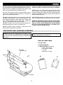
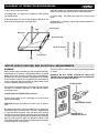
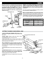
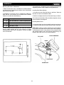
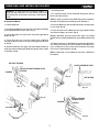
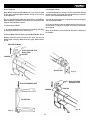
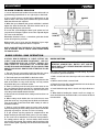
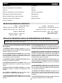
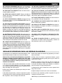
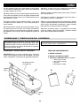
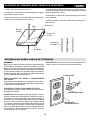
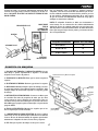
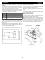
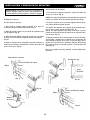
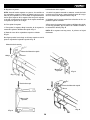
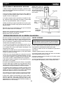
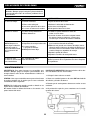
Sierra caladora de
16
”
(406.4 mm)
Scroll saw
KN SS-162
KN SS-162
INDEX
Specifications
2
General safety rules for power tools
2
Additional safety rules for scroll saw
3
Unpacking
4
Glossary of terms for woodworking
4
Motor specifications and electrical requirements
5
Getting to know your scroll saw
6
Assembly
Installing dust blower system
7
Installing blade guard
7
Removing and installing blades
3
Adjustment
To align the bevel indicator
10
Basic scroll saw operation
11
Maintenance
12
Trouble shooting
12
List of parts
13
Graph of parts
13
SPECIFICATIONS
Depth of 90º cut: 2” (50.8 mm)
Depth of 45º cut: 1” (25.4 mm)
Motor: 1/10 H.P. 120 V. 60 Hz.
Throat: 16” (406.4 mm)
Table size: 10” x 17” (254 x 432 mm) Table tilting: 45º (L / izq. )
Machine dimentions: Weight: net/gross: Blade lenght: 5” (127 mm)
Stroke per minute:
Stroke: 3/4” (19 mm)
1,725
23-3/8” x 12-1/2” x 13-3/8”
(594 x 317.5 x 340 mm)
large - width - height
21/23 Kgs.
GENERAL SAFEW RULES FOR POWER TOOLS:
WARNING: When using electric tools the following basic safety precautions should always be followed to reduce the
risk sf fire, eEectric shock and personal injury.
7. USE FUGHT TOOL. Don’t force tool or attachment to do a
job for which it was not designed. Do not use tools for purposes not intends; for example do not use circular saws to cut
tree limbs or logs.
PLEASE READ ALL THESE INSTRUCTIONS
BEFORE ATTEMPTING TO OPERATE THIS
PRODUCT.
1. KEEP WORK AREA CLEAN. Cluttered areas and benches
invite accidents.
8. WEAR PROPER APPAREL. Do not wear loose clothing,
gloves, neckties, rings, bracelet, or others jewellery, which
may get caught in moving, parts. No slip footwear is recommended. Wear protective hair covering to contain long hair.
Roll long sleeves above elbows.
2. DON’T USE IN DANGEROUS ENVIRONMENT. Do not use
power tools in damp or wet location, or expose them to rain.
Do not operate them in an area with flammable liquids or gases. Keep work area well lighted.
3. GUAIRD AGAINST ELECTRIC SHOCK. Avoid body contact
with earthed or grounded surfaces.
9. PLWAYS USE SAFETY. GOGGLES Everyday glasses only
have impact resistant lenses, they are NOT safety glasses.
Also use face or dust mask if butting operation is dusty.
4, KEEP CHILDREN AWAY. Ml visitors should be kept at a
safe distance from work area. Do not let visitors touch the tool
or extension cord.
10. CONNECT DUS1 EXTRACTION EQUIPMENT. If devices
are provided for connection of dust extraction and collecting
facilities ensure these are connected and properly used.
5. MAKE WORKSHOP CHILD PROOF. Lock access of your
workshop. When not in use, tools should be stored in a dry
locked up place, out of reach of children.
11. DO NOT ABUSE THE CORD. Do not use cord to disconnect during operation. Never yank the cord to disconnect it
from the socket Keep the cord sway heat, oil and sharp edges.
6. DON’T FORCE TOOL. It will do the job better and safer at
the rate for which it was designed.
1
12. SECIJRE WORK. Use clamps or a vice to hold work when
practical. It is safer than using your hand and it frees both
hands to operate tool.
20. CHECK DAMAGED PARTS. Before further use of the
tool, a guard or other part that is damaged should be carefully checked to determine that it will operate properly and
perform its intended function check for alignment of moving
parts, binding of moving parts, breakage of parts, mounting,
and any other conditions that may affect its operation. A guard
or other part that is damaged should be properly repaired and
replaced. by an authorized service centre. Unless otherwise
indicated in ~is instruction manual. Have defective switches
replace by authorized service centre. Do not use tool if switch
does not turn it on and off.
13. DON’T OVERREACH. Keep proper footing and balance
at all times.
14. MAINTAIN TOOL WITH CARE. Keep tool sharp and clean
for best and safest performance. Follow instructions for lubrication and changing accessories. Inspect tool cords periodically and if damages have repaired by an authorized service facility. Inspect extension cords periodically and replace
if damaged. Keep handles dry, clean and free from oil and
grease.
21. USE RECOMMENDED ACCESSORIE5. Consult the
owner’s manual for recommended accessories. The use of improper accessories may cause risk of injury to persons.
15. DISCONNECT TOOLS before servicing; when changing
accessories, such as blades, bits, cutters and the like.
22. HAVE YOUR TOOL REPAIRED BY A QUALIFIED PERSON. This electric tool is in accordance with the relevant
safety rules. Repairs should only be carried out by qualified in
considerable danger to the user.
16. REMOVE ADJUSTING KEYS AND WRENCHES. Form
habit of checking to see that keys and adjusting wrenches are
removed from tool before turning it on.
23. SAVE THESE INSTRUCTlONS. Read these instructions
and save these instructions for operating guide.
17. AVOID UNINTENTIONAL STARTING. Ensure switch is off
when plugging in.
24. KEEP GUARDS IN PLACE, and in working order.
18. USE PROPER EXTENSION CORD. Make sure your extension cord is in good condition. When using an extension
cord, be sure to use one heavy enough to carry the current
your product will draw. An undersize cord will cause a drop in
line Voltage resulting in loss of power and overheating. When
tool is used outdoors, use only extension cords intended for
outdoor use and so marked.
25. NEVER STAND ON TOOL. Serious injury could occur if the
tool is tipped or it cuffing tool is unintentionally contacted.
26. DIRECTION OF FEED. Feed work into a blade or cutter
against the direction of rotation of the blade or cutter only.
27. NEVER LEAVE TOOL RUNNING UNATTENTED. TURN POWER OFF. Don’t leave tool until it comes to a complete
stop.
19. ALWAYS KEEP ALERT. Do not let familiarity gained from
frequent use of your tool cause a careless mistake. Always
remember that a careless fraction of a second is sufficient to
inflict severe injury. Watch what you are doing: Use common
sense. Do not operate tool when you are tired.
28. THINK SAFETY. Safety is a combination of common sense
and alertness whenever the tool is in operation.
ADDITIONAL SAFETY RULES FOR SCROLL SAW:
Safety is a combination of operator common sense and alertness at all times when the scroll saw is being used.
5. Avoid awkward hand positions where a sudden slip could
cause a hand to move into the blade.
WARNING: FOR YOUR OWN SAFETY, DO NOT ATTEMPT TO
OPERATE YOUR SCROLL SAW UNTIL IT IS COMPLETELY ASSEMBLED AND INSTALLED AND ACCORDING TO THE INSTRUCTIONS...AND UNTIL YOU READ AND UNDERSTAND THE FOLLOWING:
6. Never turn your scroll saw “ON” before clearing the table
of all objects (tools, Scraps of wood, etc.,) except for the work
piece and related feed or support devices for the operation
planned.
1. Your scroll saw must be bolted securely to a stand or work
bench. In addition, if there is any tendency for the scroll saw
to move during certain operations, bolt your scroll saw stand
or workbench to the floor.
7. Make sure the blade teeth point downward toward the table.
8. Always adjust blade tension correctly.
9. When cutting a large piece of material, make sure it is supported at table height.
2. This scroll saw is intended for indoor use only.
10. Hold the work firmly against the table.
3. Wear safety goggles that comply with ANSI Z87.1 and a
face shield if operation is dusty, Wear earplugs or muffs during extended periods of operation. Do not wear gloves or roll
long sleeves above the elbow.
11. Do not feed the material too fast while cutting. Only feed
the material fast enough so that the blade will cut. Keep fingers away from the blade.
4. Do not cut pieces of material too small to hold by hand.
2
12. Use caution when cutting off material that is irregular in
cross section that could pinch the blade before the cut is completed. A piece of molding for example must lay flat on the
table and not be permitted to rock while being cut.
17. Turn was “OFF” and remove plug from power supply outlet before installing or removing an accessory or attachment.
18. Should any part of this scroll saw be missing, bent or
fail in any way, or any electrical component fail to perform
properly, shut off power switch and remove plug from power
supply outlet, Replace damaged, missing, and/or failed parts
before resuming operation.
13. Use caution when cL1ting off round material such as
dowel rods, or tubing. they have a tendency to roll while being cut causing the blade to “bite’’.
14. When backing the blade out of the workpiece, the blade
may bind in the kerf (cut).... this is usually caused by sawdust clogging up the kerf. If this happens: Turn off the scroll
saw.... remove plug from power source outlet... wedge open
the kerf... back, the blade out of the work piece.
15. Never leave the scroll saw work area with the power on,
before the machine has come to a complete stop.
19. Think Safety. Safety is a combination of operator common
sense and alertness whenever the scroll saw is in operation.
WARNING: ALWAYS KEEP ALERT. DO NOT ALLOW FAMILIARITY (GAINED FROM FREQUENT USE OF YOUR SCROLL SAW) TO CAUSE A CARELESS MISTAKE ALWAYS REMEMBER THAT A CARELESS FRACTION OF A SECOND IS SUFFICIENT TO INFLICT SEVERE INJURY.
16. Do not perform layout, assembly, or setup work on the
table while the cutting tool is operating.
UNPACKING AND CHECKING CONTENTS
WARNING For your own safety, never connect plug to power source outlet until all assembly Steps are completed, and
you have read and understood the safety and operational
instructions.
CAUTION: Never lift this saw by the arm which holds the
blade or damage will occur to your saw.
TABLE OF LOOSE PARTS
A. SCROLL SAW
B. OWNER’S MANUAL
C. LOOSE PARTS BAG (including)
1. Blade guard assembly
Do not lift
saw by this arm
Lift here
Lift here
3
2. Pin end plain end blade
3. T wrench
4. Dust blower assembly
GLOSSARY OF TERMS FOR WOODWORKING
1. Kerf the slot cut by the blade.
4. Blade Tooth Set the distance that the edge of the saw blade
tooths is bent (on set) outward from the side of the blade.
2. Leading Edge the edge of the workpiece, which pushed
into the blade first
5. Trailing Edge the work piece edge last cut by the saw
blade.
3. Saw blade Path the area of the workpiece directly in line
with and moving toward the saw blade edge.
6. Work Piece the Item on which the cutting operations is
being performed.
Leading Edge
Kerf
Workpiece
Saw blade Path
Blade Toofth Set
Trailing Edge
MOTOR SPECIFICATIONS AND ELECTRICAL REQUIREMENTS
This plug requires a mating 3 conductor grounded type outlet
as shown.
WARNING:
Rating, power supply cord with plug and grounded outlet indicated hereby are according to electrical regulations of United
States and Canada. For other countries, they may be different.
Therefore, for the actual electrical rating please see marking
on this machine, however for any details of the information on
power supply cord with plug and the grounded outlet, please
consult a qualified electrical technician.
WARNING: DO NOT PERMIT FINGEIRS TO TOUCH THE TERMINALS OF PLUGS WHEN INSTALLING OR REMOVING
THE PLUG TO OR FROM THE OUTLET.
3 PRONG PLUG
This machine is equipped with a one-speed switch for greater
versatility. It is wired for operation on 110 120 volts, 60 Hz,
alternating current.
CONNECTING TO POWER SUPPLY OUTLET
If power cord is worn or cut, or damaged in any way, have it
replaced immediately.
GROUNDING PRONG
WARNING Improper grounding can shock, burn or electrocute.
Grounding of this tool is necessary while in use to protect you
from electric shock or electrocution. This tool is equipped with
an approved three-conductor cord and three prong grounding type plug to fit the proper grounding type receptacle. Do
not remove grounding prong from the three-prong grounding type plug. The green (or green and yellow) conductor in the
cord is the grounding wire. Never connect the green (or green
and yellow) wire to a live terminal.
4
ALWAYS USE A
GROUNDED OUTLET
Plug power cord into an 110 120V properly grounded type
outlet. If the outlet you are planning to use for this power tool
is of the 2-prong type. DO NOT REMOVE OR ALTER THE GROUNDING PRONG IN ANY MANNER. Use an adapter as
shown below and always connect the grounding lug to known
ground. It is recommended that you have a qualified electrician replace the TWO-prong outlet with a properly grounded
THREE-prong outlet.
MAKE SURE
GROUNDING LUG
THIS IS
CONNECTED
TO A KNOWN
GROUND
SCREW
WARNING: TIHE GREEN GROUNDING LUG EXTENDING
FROM THE ADAPTER MUST E3E CONNECTED TO A PERMANENT GROUND SUCH AS TO A PROPEFILY GROUNDED OUTLET BOX NOT ALL OUTLET BOXED ARE PROPERLY GROUNDED.
If you are not sure that your outlet box is properly grounded
have it checked by a qualified electrician.
NOTE: The adapter illustrated is for use only if you already
have s properly grounded 2 prong receptacle. Adapter is not
allowed in Canada by the Canadian Electrical Code. The use
of any extension cord will cause some loss of power. Use only
3 wire extension cords, which have 3‑prong grounding type
plugs, and 3 pole receptacles, which accept the tools plug.
Extension Cord Length
3 PRONG PLUG
ADAPTER
Wire Size A. W. G.
Up to 1000 Ft. 16
100 200 Ft. 14
200 400 Ft. 10
2 PRONG
RECEPTACLE
GETTING TO KNOW YOUR SCROLL SAW
1.QUICK RELEASE AND TENSION LEVER: Allows you to
quickly loosen, or tighten the blade to its original tension with
lever action.
QUICK RELEASE AND TENSION LEVER
2.BLADE GUARD: Protects hands from blade contact.
3.BLADEHOLDER: Retain and position blade.
4.SAWDUSTBLOWER: Keeps workpiece clean for more accurate scroll cuts. For best results, always direct air flow from
blower tube at blade and workplace.
BLADE GUARD
5.0N / OFF SWITCH: Has holes provided by the switch for
a lock. This feature is intended to prevent unauthorized and
possible hazardous use by children and others. To turn saw on
push switch to the “on” position, to turn saw off push switch
to “off” position.
BLADEHOLDER
DROP FOOT
6.BEVELSCALES: Shows degree blade is tilted for bevel cutting.
SAWDUST
BLOWER
7.BLADE STORAGE CASE: Your scroll saw is equipped with a
blade storage area located on the side of the saw. The blade
storage area conveniently stores the blade adapter, allen
wrenches and both pin and plain end blades.
BLADE STORAGE CASE
BEVELSCALES
8. DROP FOOT: Prevents your workpiece from raising up from
the table.
5
0N / OFF
SWITCH
ASSEMBLY
Mounting Scroll Saw To Workbench
4. If mounting to a workbench, holes should be drilled through
supporting surface of the workbench using dimensions.
1. When mounting the saw to a workbench a solid wood bench
is preferred over a plywood bench where noise and vibration
will be more noticeable.
Installing Dust Blower System
1. Connect one end of the PVC Hose to the Brass Tube and
the other end to the of the Bellows Seat.
2. Hardware to mount this saw to a workbench is NOT supplied with the saw. However, we recommend the hardware
used be no smaller than the following.
2. Position and tighten the Brass Tube with Clamp and Knob.
3. For best result, the Brass Tube should be adjusted to direct
air bolt at blade and workpiece.
Quantity Description
4 Hex. Head Screws, 1/4 20 x Length Required
4 Flat Washers, 9/32 I.D.
Installing Blade Guard
4 Lock washer, g/321.D.
8 Hex Nuts, 1/4 20
1. Locate the blade guard and carefully install it onto the saw
as shown the blade guard to frame by bolt washer and Knob.
NOTE: When cutting at angles, the drop foot can be tilted so
it’s parallel to the table and rests flat against the workpiece.
To tilt drop foot, loosen screw, tilt toot so it’s parallel to table
and securely tighten screw. The drop foot should always be
lowered until it just rests on top of the workpiece.
3. A soft foam pad to place between your scroll saw and workbench is NOT supplied with the saw. However, we highly
recommend the use of such a pad (24”x1 2”x1/2”) to reduce
noise and vibration.
GUARD ASSEMBLY
PVC HOSE
FRONT OF SCROLL SAW
KNOB
DROP FOOT
BRASS TUBE
6
REMOVING AND INSTALLING BLADES
a 2 Installing Blade
WARNING: To avoid injury from accidental starting I always turn the switch off (“o”) and remove power cord
plug from power source before removing or replacing the
blade.
1. To install the blade, insert the Blade through the Access
Hole in the table. (Fig 3)
NOTE: In order to avoid uncontrollable lifting of the workpiece,
the teeth of the blade should always point downward.
A. Plain End Blade
2. Insert the Blade into the lower Blade Holder slot then tighten set screw. (Fig 4)
a 1 Removing Blade
1. To remove the Blade, Loosen tension on blade by first lifting
up the Quick Release Tension lever. (Fig 1)
3. Insert the other end of Blade into the upper Blade Holder
slot and then tighten set screw. (Fig 4)
2. Loosen the upper set screw on the side of the upper Blade
Holder. (Fig 2)
Slightly downward pressure against the upper arm maybe
helpful when installing the Blade into upper Blade Holder. (Fig
5)
3. Loose the lower set screw by inserting the T-¬Wrench
through the Access Hole on the side of the upper Blade Holder. (Fig 2)
4. Tighten the tension on the Blade by lowering the Quick Tension Lever and turning the Lever clockwise. Check the tensions on Blade, if too loose, turn Lever clockwise; if too tight,
turn Lever counterclockwise. (Fig-6)
4. Remove blade from the upper and lower Blade Holders by
pulling forward and lifting the Blade through the Access Hole
in the table. (Fig 3)
NOTE: If the blade is over tightened, the Lever is difficult to
be lowered.
RELEASE TENSION
SLIGHT PRESSURE HERE
QUICK RELEASE TENSON LEVER
TIGHTEN
LOOSEN
(Flg. 4)
SET SCREW
(Fig. 1)
(Fig. 5)
(Fig. 2)
QUICK RELEASE
TENSON LEVER
LOOSEN
TIGHTEN
ACCESS HOLE
(Flg. 6)
(Fig. 3)
7
B. Pin End Blade
2 Installin0 the Blade
Note: When installing Pin-End Blades, the set screws located
on the upper and lower Blade Holders should not be over or
under tightened.
1. Install the Blade by inserting one end of the Blade through
the Access Hole in the table and hook the blade pin in the pin
recess in the lower Blade Holder. (Fig 2)
The slot must be slightly wider than the thickness of the Blade.
After the Blade is installed, me blade tension mechanism will
keep the Pin End Blade in place.
2. Check to see that the pins are properly located in the upper
and lower Blade Holders.
3. To tension Blade, lower the Quick Release Tension Lever.
Check tension on Blade, if too tight, turn Lever counteclockwise. (Fig-4)
b 1 Removing the Blade
1. To remove the Blade, loosen tension on blade by first lifting
up the Quick Release Tension Lever. (Fig 1)
Note: H the Blade is over tensioned, the Lever is difficult to
be lowered.
2. Remove Blade from the upper and lower Blade Holder. (Fig 2)
Slightly downward pressure against the upper arm may be
helpful when removing Blade from the upper Blade Holder.
(Fig 3)
RELEASE TENSION
QUICK RELEASE TENSION LEVER
TIGHTEN
LOOSEN
PIN RECESS
(Fig. 2)
(Fig. 1)
QUICK RELEASE
TENSION LEVER
SLIGHT PRESSURE HERE
LOOSEN
TIGHTEN
PIN RECESS
(Fig. 4)
(Fig. 3)
8
ADJUSTMENT
TO ALIGN THE BEVEL INDICATOR
1. Loosen the bevel lock handle and move the table until it is
approximately perpendicular or at a right angle, to the blade.
2. Use a small square to set the table at 90 degrees to the
blade. If there is too much space between the square and the
blade the table must be adjusted.
SQUARE
3. When the space between the square and blade is minimal
tighten the bevel lock handle. The table should now be approximately 90 degrees to the blade.
4. Loosen the screw holding the bevel scale pointer and adjust pointer to O degree. Tighten screw. Then adjust 0 degree
set screw under the table.
SCALE
POINTER
Remember the bevel scale is a convenient guide but should
not be relied upon for precision.
Make practice cuts in scrap wood to determine if your angle
settings are correct. Adjust the table as required.
NOTE: AVOID SETTING THE EDGE OF THE TABLE AGAINST TOP OF MOTOR, WHICH COULD CAUSE NOISE WHEN THE SAW IS USED.
BEVEL
LOCK
HANDLE
SET SCREW
BASIC SCROLL SAW OPERATION
A SCROLL SAW IS BASICALLY A “CURVE CUTTING” MA- INSIDE CUTTING
CHINE. IT CAN ALSO BE USED FOR STRAIGIIT LINE CUTWARNING: TO AVOID INJURY FROM ACCIDENTAL TING OPERATIONS SUCH AS CUTTING, RIPPING, BEVSTARTING, ALWAYS TURN SWITCH “OFF” AND REELING, REFER FIG. 9 (BEVELING), FIG. 10 (SCROLLING).
MOVE SWITCH KEY BEFORE REMOVING OR REPLACPLEASE READ AND UNDERSTAND THE FOLLOWING ITEMS
ING THE BLADE.
ABOUT YOUR SCROLL SAW BEFORE ATTEMPTING TO USE THE SAW.
The scroll saw has the capability of inside cutting, to perform
1. The saw does not cut wood by itself. You allow the saw to an inside cut, proceed as follows:
cut wood by guiding the wood into the blade as it moves.
1. Drill a ¼ inch hole in the board you will use to make inside
2. The blade teeth cut wood ONLY on the down stroke.
cutting.
3. You must guide the wood into the blade slowly because the
2. Reiease tension knob, remove blade.
teeth of the blade are very small and they can only remove
wood when they are on the down stroke.
3. Place the board on the saw table with the hole in the board
4. There is a learning curve for each person who wants to use over the access hole in the table.
this saw. During that period of time it is expected that some 4. Install blade through hole in board and adjust blade tenblades will break until you learn how to use the saw and re- sion.
ceive the greatest benefit from the blades.
5. When finished making the interior scroll cuts simply re5. Best results are achieved when cutting wood less than one move the blade from the blade holder, and remove the board
inch thick
form the table.
6. When cutting wood thicker than one inch the user must
guide the wood very’ very slowly into the blade and take extra
care not to bend or twist the blade while cutting in order to
maximize blade Iife.
7. Teeth on scroll saw blades wear out and as such must be
replaced frequently for best cutting results. Scroll saw blades
generally stay sharp for 1/2 hour or 2 hours of cutting.
8. To get accurate cuts be prepared to compensate for the
blades tendency to follow the wood grain as you are cutting.
9. This scroll saw is intended to cut wood or wood products.
For cutting precious and non ferrous metals, these must be
used at very slow speeds. They perform well on machines that
have variable speed capability and should be lubricated with
beeswax.
9
Trouble Shooting
WARNING: For your own safety, turn switch “off” and remove plug from power source outlet before trouble shooting your scroll saw.
PROBLEM
PROBLEM CAUSE
REMEDY SUGGESTED
Breaking Blades
1. Wrong tension
2. Over working blades.
3. Wrong blade application.
4. Twisting blade in wood.
1.
Adjust blade tension.
2. Reduce feed rate.
3. Use narrow blades.
4. Avoid side pressure on blade.
Motor will not run
1. Defective cord or plug.
2. Defective motor.
1. Replace defective parts before using saw again.
2. Consult Service Center. Any attempt to repair this
motor may create a HAZARD unless repair is done
by a qualified service technician.
1. See mounting instructions in this manual for
proper mounting technique.
2. The heavier your work bench is the less vibration
will occur. A plywood workbench will not be as a
good work surface as the same size solid lumber.
Use common sense in choosing a mountioning surface.
3. Tighten table lock knob.
4. Tighten motor mounting screws.
Vibration
NOTE: There will
always be some
vibration present
when the saw is
running because of
the motor operation
Blade Run out
Blade not in line
with arm motion
1.
2.
3.
4.
Improper mounting
of saw.
Unsuitable mounting
surface.
Loose table or table
resting against motor.
Loose motor mounting.
Blade holders not aligned.
1. Loosen cap screws holding blade holders to arms.
Adjust position of blade holders. Retighten holders.
Maintenance
WARNING: For your own safety, turn switch “off” and remove
plug from power source outlet before maintaining or lubricating your saw.
GENERAL
An occasional coat of paste wax on the work table will allow the wood being cut to glide smoothly acroos the work
surfece.
MOTOR
If the power cord is worn, cut or dameged in any way, have it
replaced immediately.
Do not attempt to oil the motor bearings or service the motor
internal parts.
ARM BEARINGS
Lubricate the arm bearing sufter every 50 hours of use.
To do so:
1. Turn saw on its side.
2. Squirt a generous amount of SAE 20 oil
around the shaft end and bronze bearing.
3. Let the oil soak in overn ight in this condition.
4. Next day repeat the above procedures
for the opposite side of the saw.
10
LIST OF PARTS
I.D.
Description
Size
0AM2 ECCENTRIC
Description
I.D.
QTY
1
0HV9 BALL BEARING
Size
QTY
2
φ5*10-1
3
FLAT WASHER
3/16*1/2-3/64
1
0J72
FLAT WASHER
1/4*5/8-1/16
4
1
0J7F
FLAT WASHER
5/16*7/8-5/64
1
0AMW SET PLATE
2
0J91
SPRING WASHER
φ4
2
0AMX CLAMP BOLSTER
1
0J92
SPRING WASHER
φ5
1
0ANC BLADE
1
0J9F
SPRING WASHER
φ5/32
2
0C0R CLAMP BOLSTER
1
0J9H
SPRING WASHER
φ1/4”
2
0C10 BLADE
1
0J9T
SPRING WASHER
“φ5/16”
2
0C1G NEEDLE POINTER
1
0JAZ
WAVE WASHER
WW-6
2
0DEF HANDLE SEAT
1
0JC8
SPRING PIN
1
0EHY PLATE COVER
1
0JFB
SELF-LOCKING RING
1
0AM3 WASHER
D=φ9.5 , φ5 T=4
1
0J4D FLAT WASHER
0AM9 BUSH
D=φ22 L=29
2
0J6U
0AMH COMPRESSION SPRING L=16 D=φ10 DW=φ1 N=4.5 1
0AMN SHAFT SLEEVE
D=φ9.5, φ5 T=6
0EJ9 BODY
1
0JPP
HEX. HD. BOLT
M8*1.25-30
2
0EJA BUMPER
1
0JU4
HEX. SOC. HD. CAP BOLT
M4*0.7-10
2
0EKB HEX. SOC. HD. CAP BOLT
2
0JU6
HEX. SOC. HD. CAP BOLT
M4*0.7-16
4
2
0JUF
HEX. SOC. HD. CAP BOLT
M5X0.8-30
2
0EPR SEGMENT SPRING
1
0JUP HEX. SOC. HD. CAP BOLT
M6*1.0-35
1
0EPU UPPER ARM ROCKER ASS’Y
1
0JVH HEX. SOC. HD. CAP BOLT
M6*1.0-35
1
0EPY SET PLATE
2
0JZH HEX. SOC. SET SCREW
M8*1.25-8
1
0EQ5 BOTTOM ARM ROCKER ASS’Y
1
0JZV
HEX. SOC. TRUSS HD. SCREW
M5*0.8-10
10
0EQC BEARING SEAT
1
0K0R HEX. HD. SCREW AND WASHER
M6*1.0-20
4
0EQG BLADE HOLDER
2
0K0W HEX. HD. SCREW AND WASHER
M6*1.0-25
3
0EQS TABLE
1
0K28
HEX.SOCKET HD.CAP SCREWS M5X0.8-16
1
0EQV BRACKET-TILT
1
0K3G CR.RE. PAN HD. SCREW & WASHER
M5*0.8-12
1
0ER4 SUPPORT
1
0K70
CR.-RE. TRUSS HD. SCREW M4*0.7-16
2
0ERZ PLUNGER
1
0K71
CR.-RE. TRUSS HD. SCREW M5*0.8-8
3
0EPP BUSH
D=φ22 M8X1.25
0EST KNOB
1
0KDH CR. RE. PAN HD. SCREW
M5*0.8-8
1
0ESZ HANDLE
1
0KDT CR. RE. PAN HD. SCREW
M6*1.0-8
1
0FPP LINGAGE BAR
1
0KFF
CR. RE. PAN HD. SCREW
M5*0.8-8
2
1
0KMR HEX. NUT
M5*0.8 T=4
1
1
0KMS HEX. NUT
M6*1.0 T=5
1
1
0KQW LOCK NUT
M5*0.8 T=5
1
0FRK BUSH
1
0KQX NUT
M6*1.0 T=6
3
0FSK BELLOWS
1
0Q7F MOTOR
1
0FU3 BLADE BOX
1
0Z7W AIR DUCT ASS’Y
1
0G1V KNOB
1
2ZKG LABEL
1
0G4S TENSION HANDLE ASS’Y
1
2RCY BASE
1
0FQG PVC HOSE
0FR0 SPACER
0FR1 SHAFT-PIVOT
D=φ7/16 φ8.2 L=35.5
0G7X BELLOWS SEAT
1
2ZKE TRADE-MARK LABEL
1
0HG8 ROCKER ARM COVER
1
2ZKF TRADE-MARK LABEL
1
0HGA BELLOWS SEAT
1
2ZKH LABEL
1
0HJH FOLLOWER PLATE
1
2ZKJ CAUTION LABEL
1
0HJK BLADE GUARD
1
2ZKK WARNING LABEL
1
0HJN PIN
1
2ZKL STICKER
1
0HJQ KNOB
1
2ZKM STICKER
1
0HJS RETAINING CLIP
1
11
0JZV
BLA
DE
3
0EHY
0JZV
7
E
RAG
STO
0EKB
2
0Z8G
0DEF
0EJ9
0EJA
0FU3
0Z8F
0J9H
0KMS
0K3G
0Z8N
0ERZ
2RCY
0K0W
3
F
0Z8H
12
0KQX
0AMX
0FPP
0J9T
2
0JPP
0EPR
0EPP
0JC8
2
2
0C0R
0FR0
0FRK
0J7F
0FR1
0EST
E
4
0HV9
0J92
0K0R
0KQW
0AM9
0AMW
0AM9
2
2
0AMW
0J9F
0JU4
2
0AMN
0EQG
0EPY
0J91
0JU6
0EQC
0AM3
2
2
2
4
0FSK
0HG8
0EQ5
0JUF
0EPU
0K28
0Z8K
0K713
0ANC
2
0H72
0J4D
0G1V
0C10
G
E
0J4D
0JFB
0JUF
0KMR
0C1G
E
0KDT
2
0HJH
0HJK
0HJQ
0KQX 2
0ER4
0JAZ
0KDH
0HJS
26XY
0J6U
0EQS
0JZH
0AMH
3
0AM2
0J72
0HJN
0EQV
0JVH
0KFF
0Z8M
2
0Z8L
0G4S
0J9H
0Q7F
G
E
0JUP
0HGA
0FQG
0G7X
0K70
0Z7W
2
0ESZ
GRAPH 0F PARTS
INDICE
Especificaciones
Ensamblaje
Reglas de seguridad para las herramientas
Ajustes
electricas
Operacion
Reglas de seguridad para las sierras caladoras
Soluciones de problemas
Desempaque y verificación del contenido
Mantenimiento
Glosario de términos para trabajos en madera
Lista de partes
Información sobre cables de extensión
Diagrama de partes
Conozca su máquina
ESPECIFICACIONES DEL PRODUCTO
Motor: 1/10 H.P. 120 V. 60 Hz.
Carreras: 19 mm (3/4”)
Máximo espesor de corte a 90°: 50.8 mm (2”)
Máximo espesor de corte a 45°: 25.4 mm (1”)
Inclinación de la mesa: 45° a la izquierda
Dimensiones de la máquina: 584 x 318 x 318 mm
(23 x 12 1/2 x 12 1/2”)
(largo x ancho x alto)
Garganta: 406 mm (16”)
Largo de la segueta: 127 mm (5”)
Mesa de trabajo: 254 x 432 mm (10 x 17”)
Golpes por minuto: 1,720
REGLAS DE SEGURIDAD PARA LAS HERRAMIENTAS ELECTRICAS
WARNING: When using electric tools the following basic safety precautions should always be followed to reduce the
risk sf fire, eEectric shock and personal injury.
Por favor lea estas instrucciones antes de operar
este producto.
1. MANTENGA LIMPIA EL ÁREA DE TRABAJO. Las áreas y
mesas desordenadas atraen accidentes. El piso no debe estar
resbaloso debido a cera o aserrín.
2. EVITE LOS AMBIENTES PELIGROSOS. No use la máquina
en zonas húmedas o mojadas, ni la exponga a la lluvia. Conserve bien iluminada el área de trabajo. Debe contar con espacio suficiente en el área de trabajo.
3. PROTÉJASE CONTRA CHOQUES ELÉCTRICOS. Evite el
contacto con superficies aterrizadas.
4. MANTENGA ALEJADOS A LOS NIÑOS. Todos los visitantes deben permanecer a una distancia segura del área de
trabajo.
5. HAGA SU TALLER A PRUEBA DE NIÑOS con candados,
interruptores maestros, o quitando los interruptores de encendido.
6. NO FORCE LA MAQUINA. Esta hará el trabajo mejor y
más seguro si se usa para lo que fue diseñada.
7. USE LA HERRAMIENTA ADECUADA. No force la máquina
o algún aditamento para hacer un trabajo para el cual no fue
diseñada.
13
8. USE ROPA ADECUADA. No use ropa holgada, guates, corbata o joyería (anillos, reloj) que se puedan atorar en partes
móviles. Se recomienda usar calzado antiderrapante. Sujete
el cabello largo. Suba las mangas largas arriba del codo.
9. USE LENTES DE PROTECCIÓN (PROTECCIÓN PARA LA
CABEZA). Use siempre lentes de protección. Los anteojos de
uso diario sólo tienen lentes resistentes al impacto. NO son
lentes de protección. También, use careta o mascarilla si la
operación de corte es polvosa, y use tapones en los oídos
durante periodos largos de operación.
10. CONECTE EQUIPO DE EXTRACCIÓN DE POLVO. Si los
aparatos cuentan con conexión para accesorios de extracción
y recolección de polvo, asegúrese de que sean conectados y
usados adecuadamente.
11. NO MALTRATE EL CABLE. No use el cable para desconectar la máquina durante la operación. Nunca jale el cable
para desconectar del contacto. Mantenga el cable alejado del
calor, aceite o bordes filosos.
12. ASEGURE LA PIEZA DE TRABAJO. Use prensas para
sostener la pieza de trabajo cuando sea posible. Es más seguro que usar las manos y libera ambas manos para operar
la máquina.
13. NO SE ESTIRE MAS ALLÁ DE SU ALCANCE. Mantenga
los pies bien apoyadas en el piso y balanceados.
14. CUIDE SU HERRAMIENTA. Mantenga sus herramientas
afiladas y limpias para un desempeño mejor y más seguro. Siga
las instrucciones para lubricación y cambio de accesorios.
21. USE LOS ACCESORIOS RECOMENDADOS. Consulte
el manual del propietario para los accesorios recomendados.
El uso de accesorios inadecuados puede generar riesgos.
15. DESCONECTE LA MÁQUINA. Antes de darle servicio o
cuando cambie accesorios.
22. HAGA QUE PERSONAL CALIFICADO REPARÉ SU MÁQUINA. Esta herramienta eléctrica cumple con las reglas de
seguridad relevantes. Las reparaciones deben ser realizadas
únicamente por personal calificado. Si no se hace así, se puede provocar daños considerables al usuario.
16. RETIRE LAS LLAVES DE AJUSTE. Fórmese el hábito de
verificar que todas las herramientas se retiren de la máquina
antes de encenderla.
17. EVITE EL ENCENDIDO ACCIDENTAL. Asegúrese de que
el interruptor esté en la posición APAGADO (OFF) antes de
conectar la máquina.
18. USE CABLES DE EXTENSIÓN ADECUADOS. Asegúrese
de que su cable de extensión esté en buenas condiciones.
Cuando use un cable de extensión, asegúrese de usar el calibre adecuado para transmitir la corriente que usará su máquina. El uso de un calibre menor al necesario causará una
pérdida de voltaje que resulta en una pérdida de potencia y
sobre calentamiento. Cuando use la máquina en exteriores,
use únicamente cables diseñados para usarse en exterior.
19. MANTÉNGASE SIEMPRE ALERTA. No permita que la familiaridad ganada por el uso frecuente de la herramienta provoque un error por descuido. Recuerde siempre que un descuido por una fracción de segundo es suficiente para ocasionar
daños severos. Fíjese en lo que este haciendo. Use el sentido
común. No opere la herramienta cuando esté cansado.
20. CHEQUE LAS PARTES DAÑADAS. Antes de seguir usando la máquina, una protección u otra parte que esté dañada
se debe checar para asegurarse de que realizará su función.
Verífique a alimentación de partes móviles, montaje, rotura de
piezas y cualquier otra condición que pueda afectar su operación. Si una parte está dañada se debe reparar o reemplazar
de inmediato.
23. GUARDE ESTAS INSTRUCCIONES. Lea estas instrucciones y guárdelas como guía de operación.
24. CONSERVE LAS PROTECCIONES EN SU LUGAR. En
buenas condiciones y ajústelas.
25. NUNCA SE PARE SOBRE LA MÁQUINA. Se puede lastimar seriamente si la máquina se inclina o si se contacta la
sierra accidentalmente.
26. DIRECCIÓN DE ALIMENTACIÓN. Alimente la pieza de
trabajo a la sierra, únicamente contra la dirección de rotación
de la sierra o cuchilla.
27. NUNCA DEJE FUNCIONAR LA MÁQUINA SIN ATENCIÓN. Apáguela. No se aleje hasta que se detenga por completo.
28. PIENSE DE MANERA SEGURA. La seguridad es una
combinación de sentido común del operador y atención en
todo momento cuando se usa la herramienta
REGLAS DE SEGURIDAD PARA LAS SIERRAS CALADORAS
La seguridad es una combinación común del operador y atención en todo momento cuando se usa la sierra caladora.
4. No corte pedazos de material muy pequeños para sostenerlos con la mano.
PRECAUCIÓN: POR SU PROPIA SEGURIDAD, NO INTENTE OPERAR LA SIERRA CALADORA HASTA QUE ESTÉ COMPLETAMENTE ENSAMBLADA E INSTALADA DE ACUERDO
A LAS INSTRUCCIONES Y HASTA QUE HAYA LEÍDO Y ENTENDIDO LO SIGUIENTE:
5. Evite colocar las manos en posiciones extrañas, ya que
un deslizamiento repentino puede provocar que la mano se
mueva hacia la sierra.
1. Su sierra caladora debe atornillarse firmemente a una base
o a un banco de trabajo. Además, si la sierra tiene tendencia a moverse durante ciertas operaciones, atornille la base o
banco de trabajo de la sierra al piso.
2. Esta sierra caladora está diseñada para trabajar en interiores únicamente.
3. Use lentes de protección y careta si la operación es polvosa. Use tapones en los oídos en periodos largos de operación.
No use guantes, suba las mangas arriba del codo.
6. Nunca encienda la sierra antes de quitar los objetos de
la mesa (herramientas, retazos de madera, etc.) a excepción
de la pieza de trabajo y medios para alimentar o sostener la
pieza, de acuerdo a la operación planeada.
7. Asegúrese de que los dientes de la sierra apunten hacia
abajo, hacia la mesa.
8. Ajuste siempre la tensión de la sierra correctamente.
9. Cuando corte materiales grandes asegúrese de que se
sostenga al nivel de la mesa.
10. Sostenga la pieza firmemente sobre la mesa.
14
11. No alimente la pieza muy rápido mientras corta. Hágalo
a una velocidad suficiente para que la sierra corte. Mantenga
los dedos alejados de la sierra.
12. Tenga cuidado al cortar material irregular, puede atorar la
sierra antes de completar el corte. Un pedazo amoldado debe
descansar plano sobre la mesa y no se debe permitir que se
meza mientras se corta.
13. Tenga cuidado al cortar material redondo, ya que tiene
la tendencia de rodar mientras se corta, ocasionando que la
sierra “muerda”.
14. Cuando retire la segueta de la pieza de trabajo, la segueta puede atorarse en el corte, esto se debe usualmente a
que hay aserrín en el corte. Si esto pasa: Apague la máquina,
desconéctela, abra el corte, retire la segueta de la pieza de
trabajo.
15. Nunca se aleje de la sierra cuando esté encendida, ni
antes de que la sierra se detenga completamente.
16. No ensamble o prepare trabajo sobre la mesa cuando la
sierra esté operando.
17. Apague la máquina y desconéctela antes de instalar o
retirar algún accesorios o aditamento.
18. En caso de que alguna pieza falte, esté doblada o dañada
o algún componente eléctrico no funcione correctamente. Apague la sierra, desconéctela y reemplace o repare cualquier
parte defectuosa antes de continuar trabajando.
19. Piense de manera segura. La seguridad es una combinación de sentido común del operador y atención siempre
que la sierra caladora esté funcionando.
DESEMPAQUE Y VERIFICACION DEL CONTENIDO
ATENCIÓN: Siempre manténgase alerta. No permita qufe
la familiaridad (obtenida por el uso frecuente de la sierra
caladora) provoque un error por descuido. Recuerde siempre que una fracción de segundo de descuido es suficiente
para causar lesiones graves.
PRECAUCIÓN. Nunca levante la sierra caladora por el
brazo que sujeta la sierra, se puede dañar
DESEMPAQUE Y VERIFICACIÓN DEL CONTENIDO.
TABLA DE PIEZAS SUELTAS.
ADVERTENCIA: Por su propia seguridad, nunca conecte la
clavija hasta completar los pasos de ensamblaje y que haya
leído y entendido las instrucciones de seguridad y operación.
A. SIERRA CALADORA.
B. MANUAL DE INSTRUCCIONES
C. BOLSA DE PIEZAS SUELTAS (que incluye)
1. Blade guard assembly
No levante la sierra
con este brazo
Levantar
aqui
Levantar
aqui
15
2. Pin end plain end blade
3. T wrench
4. Dust blower assembly
GLOSARIO DE TERMINOS PARA TRABAJOS EN MADERA
1. Corte – la ranura cortada por la sierra.
4. Acomodo de los dientes de la sierra – la distancia que la
punta de los dientes de la sierra están doblados hacia fuera
desde el extremo de la sierra.
2. Borde inicial – el borde de la pieza de trabajo que es empujado primero y hacia la sierra.
5. Borde final – el borde de la pieza de trabajo que la sierra
corta finalmente.
3. Trayecto de la sierra – el área de la pieza de trabajo directamente en línea y moviéndose hacia la sierra.
6. Pieza de trabajo – el artículo sobre el cual se realiza el trabajo de corte.
Borde inicial
Corte
Pieza de
trabajo
Trayecto de
la sierra
Acomodo de
los dientes
Borde final
INFORMACION SOBRE CABLES DE EXTENSION
WARNING:
Rating, power supply cord with plug and grounded outlet indicated hereby are according to electrical regulations of United
States and Canada. For other countries, they may be different.
Therefore, for the actual electrical rating please see marking
on this machine, however for any details of the information on
power supply cord with plug and the grounded outlet, please
consult a qualified electrical technician.
ADVERTENCIA: No toque con los dedos las terminales de las
clavijas cuando las conecte o desconecte del contacto.
3 PRONG PLUG
ESPECIFICACIONES DEL MOTOR Y REQUERIMIENTOS
ELÉCTRICOS.
Esta máquina está equipada con un interruptor de una velocidad para mayor versatilidad. Está cableado para operar a 127
+- 10%, 60 Hz, corriente alterna.
CONEXIÓN AL CONTACTO DE ENERGÍA ELÉCTRICA.
Si el cable está gastado o cortado, dañado en cualquier forma,
cámbielo de inmediato.
ADVERTENCIA. Un aterrizaje inadecuado puede dar choque,
quemar o electrocutar. El aterrizaje de la máquina es necesario mientras se usa para protegerlo contra choques eléctricos
o electrocución, ésta máquina está equipada con un cable de
tres líneas y una clavija de tres puntas que se debe conectar
a un contacto aterrizado de tres orificios. No quite la punta de
tierra de la clavija. El conductor verde (o verde y amarillo) del
cable es el cable de tierra. Nunca conecte el cable de tierra a
una terminal viva. Esta clavija requiere un contacto aterrizado
de tres orificios como se muestra.
16
GROUNDING PRONG
ALWAYS USE A
GROUNDED OUTLET
Conecte el cable a un contacto debidamente aterrizado. Si el
contacto en el que planea conectar la máquina es de dos orificios, NO QUITE O ALTERE LA PUNTA DE TIERRA DE NINGUNA FORMA.
GROUNDING LUG
SCREW
Use un adaptador como se muestra y siempre conecte el
adaptador a una tierra conocida. Se recomienda que un electricista calificado cambie el contacto de dos orificios por uno
de tres orificios, debidamente aterrizado. Si no está seguro
de que su contacto esté debidamente aterrizado, haga que lo
verifique un electricista calificado.
NOTA: El adaptador ilustrado se debe usar únicamente si
usted cuenta con un contacto de dos orificios debidamente
aterrizado. El uso de cualquier extensión causará alguna pérdida de potencia. Use únicamente cables de extensión de tres
líneas que tengan clavijas de tres puntos y contactos aterrizados correspondientes.
MAKE SURE
THIS IS
CONNECTED
TO A KNOWN
GROUND
Largo de la extención
3 PRONG PLUG
ADAPTER
Calibre del cable AWG
Hasta 30 mts. 16
De 30 a 60 mts. 14
de 60 a 120 mts. 10
2 PRONG
RECEPTACLE
CONOZCA SU MAQUINA
1. PALANCA DE TENSIÓN Y LIBERACIÓN RÁPIDA. Le permite aflojar o apretar rápidamente la segueta a su tensión
original con una acción de palanca.
Palanca de tensión y liberación rápida
2. GUARDA DE LA SEGUETA. Evita que las manos toquen la
segueta.
3. SUJETADOR DE SIERRA. Sostiene y posiciona la segueta.
4. SOPLADOR. Mantiene limpia la pieza de trabajo para hacer cortes más exactos. Para obtener mejores resultados, dirija
siempre el flujo de aire del tubo soplador a la segueta y pieza
de trabajo.
Guarda
de la sierra
Sujetador
de la sierra
5. INTERRUPTOR DE ENCENDIDO. Cuenta con orificios para
un candado. Esto tiene el propósito de evitar que los niños
u otras personas usen la máquina sin autorización. Para encender la sierra presione el interruptor a la posición de encendido (ON), para apagarla oprima el interruptor a la posición de
apagado (OFF).
Pie
Soplador
6. ESCALA DE BISELADO. Muestra los ángulos que se inclina la siegueta para cortar biselados.
Compartimento
para seguetas
Escala de
biselado
7. COMPARTIMENTO PARA SEGUETAS. Su sierra caladora
cuenta con un área de almacenaje localizada en el costado de
la sierra. El área de almacenamiento de seguetas guarda eficientemente el adaptador de sierra, llaves allen y seguetas.
8. PIE. Evita que la pieza de trabajo se suba por la sierra.
17
Interruptor
del encendido
ENSAMBLE
MONTAJE DE LA SIERRA CALADORA A UN BANCO DE INSTALACIÓN DEL SOPLADOR.
TRABAJO.
1. Conecte un extremo de la manguera de PVC al tubo de
1. Cuando monte la sierra a un banco de trabajo, se recomien- bronce y el otro extremo al asiento del fuelle.
da usar un banco de madera sólida en lugar de uno de triplay,
donde el ruido y la vibración serán menos notorios.
2. Posicione y apriete el tubo de bronce con la prensa y la
2. No se incluye la tornillería para montar la sierra a un ban- perilla.
co de trabajo. Sin embargo, recomendamos que la tornillería
usada no sea más pequeña que lo siguiente:
Cantidad Descripción
4 Tornillos 1/4-20, del largo necesario
4 Roldanas planas 9/32”
4 Roldanas de presión 9/32”
8 Tuercas 1/4-20
3. Para mejores resultados, el tubo de bronce se debe dirigir
a la sierra y la pieza de trabajo.
INSTALACIÓN DE LA GUARDA.
1. Posicione la guarda e instálela con cuidado sobre la sierra
como se muestra con tornillo, roldana y perilla.
3. No se incluye un cojín de hule espuma para colocarse entre
la sierra y el banco de trabajo. Sin embargo recomendamos
que se use dicho cojín (24” x 12” x 1/2”) para reducir el ruido
y la vibración.
NOTA:Cuando corte ángulos, el pie se puede inclinar de
manera que esté paralelo con la mesa y descanse plano sobre
la pieza de trabajo. Para inclinar el pie, afloje el tornillo, incline
el pie y apriete el tornillo. El pie se debe bajar siempre hasta
que descanse sobre la superficie de la pieza de trabajo.
4. Cuando monte la sierra a un banco de trabajo, se deben taladrar orificios en la superficie de soporte del banco de trabajo
usando las dimensiones de ilustración.
Ensamblaje
de la guarda
Manguera de PVC
Frente de la sierra caladora
Perilla
Inclinación
del pie
Tubo de bronce
18
INSTALACIÓN Y REMOCIÓN DE SEGUETAS.
A.2 Instalación de la segueta.
ADVERTENCIA: Para evitar lesiones por encendido accidental, siempre apague la sierra y desconéctela de la
corriente eléctrica antes de quitar o cambiar la segueta.
1. Para instalar la segueta, insértela a través del orificio de
acceso en la mesa. (Fig. 3)
NOTA: Para evitar levantamiento incontrolable de la pieza de
trabajo, los dientes de la sierra deben apuntar hacia abajo.
A. Segueta sin pernos.
2. Inserte la segueta en la ranura del sujetador inferior de sierra, luego apriete el tornillo. (Fig. 4)
A.1 Para quitar la segueta.
1. Para quitar la segueta, afloje la tensión de la sierra levantando la palanca de liberación rápida. (Fig. 1)
2. Afloje el tornillo superior en el costado de sujetador superior de segueta. (Fig. 2)
3. Afloje el tornillo inferior insertando la llave T por el orificio
de acceso en el costado del sujetador inferior de segueta.
(Fig. 2)
4. Retire la segueta de los sujetadores superior e inferior jalándola hacia delante y levantándola a través del orificio de
acceso en la mesa. (Fig. 3)
3. Inserte el otro extremo de la segueta en el sujetador superior de sierra y luego apriete el tornillo. (Fig. 4)
Ejercer una ligera presión hacia abajo en el brazo, superior
puede ser útil cuando instale la segueta en el sujetador superior de sierra. (Fig. 5)
4. Apriete la tensión de la sierra bajando la palanca de liberación rápida y girándola en el sentido de las manecillas del
reloj. Cheque la tensón de la sierra, si está muy floja, gire la
palanca en el sentido de las manecillas del reloj. Si está muy
floja, gire la palanca en sentido contrario a las manecillas del
reloj. (Fig. 6)
Nota: si la segueta está muy apretada, costará trabajo bajar
la palanca.
Liberación de la tensión
Presión leve aquí
Palanca de liberación rápida
Tensar
Aflojar
(Flg. 4)
(Fig. 1)
Juego
de tornillo
(Fig. 5)
(Fig. 2)
Aflojar
Palanca de liberación rápida
Tensar
Orificio
de acceso
(Flg. 6)
(Fig. 3)
19
B. Segueta con pernos
b-2 Instalación de la segueta.
NOTA: Cuando instale seguetas con pernos, los tornillos en
los sujetadores superior e inferior no deben estar muy apretados ni poco apretados. La ranura debe ser ligeramente más
ancha que el espesor de la segueta. Una vez que la segueta
se instaló, el mecanismo de tensión de la segueta mantendrá
la segueta con pernos en su lugar.
1. Instale la segueta insertando un extremo a través del orificio de acceso en la mesa y enganchando el perno de la segueta en la muesca del sujetador inferior. (Fig. 2)
b.1 Para quitar la segueta.
3. Para tensar la segueta, baje la palanca de liberación rápida,
si está muy apretada, gire la palanca en sentido contrario a
las manecillas del reloj. (Fig. 4)
1. Para quitar la segueta, afloje la tensión de la segueta levantando la palanca de liberación rápida. (Fig. 1)
2. Retire la sierra de los sujetadores superior e inferior.
(Fig. 2)
2. Verifique que los pernos estén bien colocados en los sujetadores superior e inferior.
NOTA: Si la segueta está muy tensa, la palanca no bajará
fácilmente.
Una ligera presión hacia abajo en el brazo superior es útil al
quitar la segueta del sujetador superior. (Fig. 3)
Liberación de la tensión
Palanca de liberación rápida
Tensar
Aflojar
Muesca del
sujetador
(Fig. 2)
(Fig. 1)
Presión leve aquí
Palanca de liberación rápida
Aflojar
Tensar
Muesca del
sujetador
(Fig. 4)
(Fig. 3)
20
AJUSTE
PARA ALINEAR EL INDICADOR DEL BISELADO.
1. Afloje la manija aseguradora de ángulos y mueva la mesa
hasta que esté aproximadamente perpendicular, o en ángulo
recto con la segueta.
2. Use una escuadra pequeña para colocar la mesa a 90º con
la segueta. Si existe mucho espacio entre la escuadra y la
segueta, la mesa se debe ajustar.
NOTA: Evite colocar el
borde de la mesa contra la superficie superior
del motor porque puede
causar ruido cuando se
usa la sierra.
3. Cuando el espacio entre la escuadra y la segueta es mínimo, apriete la manija aseguradora de ángulos. La mesa debe
estar ahora aproximadamente a 90º con la segueta.
Escuadra
Apuntador
de la
escudra
4. Afloje el tornillo que sujeta el apuntador de la escala y ajústelo a 0º. Apriete el tornillo. Luego ajuste el tornillo de 0º debajo de la mesa.
Recuerde que la escala de biselado es una guía conveniente
pero no se debe confiar en su exactitud.
Manija
aseguradora
de ángulos
Realice cortes de práctica en madera de desperdicio para determinar si el acomodo de ángulo es correcto.
Ajuste la mesa como sea necesario.
Tornillo
OPERACIÓN BÁSICA DE LA SIERRA CALADORA.
Una sierra caladora es, básicamente, una máquina cortadora
de curvas. También se puede usar para cortes en línea recta
tales como cortes al hilo, cortes cruzados, biselados. Por favor lea y entienda los siguientes puntos acerca de su sierra
caladora antes de intentar usar la sierra.
1. La sierra no corta madera por si sola. Usted le permite a la sierra cortar madera guiándola a la segueta mientras ésta se mueve.
2. Los dientes de la sierra cortan madera únicamente en el
movimiento hacia abajo.
3. Debe guiar la madera hacia la sierra lentamente porque los
dientes de la sierra son muy pequeños y sólo quitan madera
cuando se mueven hacia abajo.
4. Existe una curva de aprendizaje para cada persona que desea usar esta sierra. Durante ese periodo de tiempo, se espera que algunas seguetas se rompan hasta que aprenda cómo
usar la sierra y reciba a máximo beneficio de las seguetas.
5. Se obtienen mejores resultados al cortar madera de un espesor menor a una pulgada.
CORTES INTERNOS
ADVERTENCIA: Para evitar lesiones por encendidos accidentales. Siempre apague la máquina y desconéctela de la
energía eléctrica antes de quitar o cambiar las seguetas.
La sierra caladora tiene la capacidad de hacer cortes internos.
Para realizar un corte interno, proceda como sigue:
1. Taladre un orificio de 1/4” en la madera en la que hará el
corte interno.
2. Afloje la perilla de tensión, retire la segueta.
3. Coloque la madera sobre la mesa de la sierra con el orificio
sobre el orificio de acceso en la mesa.
4. Instale la segueta a través del orificio en la madera y ajusta
la tensión de la segueta.
5. Cuando termine de hacer el corte interior, simplemente retire la segueta del sujetador y retire la madera de la mesa.
6. Cuando corte madera de un espesor mayor a una pulgada,
el usuario debe guiar la madera muy, muy despacio hacia la
segueta y tener cuidado excesivo de no doblar o torcer la segueta mientras corta para maximizar la vida de la segueta.
7. Los dientes de las seguetas para caladora se gastan y éstas
se deben cambiar frecuentemente para obtener mejores resultados de corte. Las seguetas para caladora generalmente
permanecen afiladas de 1/2 hora a 2 horas de corte.
8. Para obtener cortes exactos, prepárese a compensar la tendencia de las seguetas a seguir la veta de la madera mientras corta.
9. Esta sierra caladora está diseñada para cortar madera o
productos de madera. Para cortar metales preciosos y o-ferrosos, se debe usar a velocidades muy bajas. Estos se desempeñan bien en máquinas que tienen velocidad variable y se
deben lubricar con cera de abeja.
21
SOLUCIONES DE PROBLEMAS
ADVERTENCIA: Para evitar lesiones por encendidos accidentales. Siempre apague la máquina y desconéctela de
la energía eléctrica antes de solucionar problemas de su
sierra caladora.
PROBLEMA
¿QUE ESTA MAL?
¿QUE HACER?
La sierra se rompe.
1. Tensión incorrecta.
2. Sierra sobre trabajada.
3. Incorrecta aplicación de la sierra.
4. La sierra se tuerce en la madera.
1. Ajuste la tensión de la sierra.
2. Reduzca la velocidad de alimentación.
3. Use sierras más delgadas.
4. Evite presión lateral en la sierra.
El motor no arranca.
1. Cable o clavija defectuosos
2. Motor defectuoso.
1. Cambie las partes defectuosas antes de
volver a usar la sierra.
2. Consulte al centro de servicio cualquier intento
de reparar el motor es peligroso, a menos que
se realice por un técnico de servicios calificado
1. Montaje incorrecto de la sierra.
2. Superficie de montaje inadecuada.
3. La mesa está floja
o apoyada en el motor.
4. Montaje del motor flojo.
1. Vea las instrucciones de montaje en este manual
para la técnica adecuada de montaje.
2. Mientras más pesado sea el banco de trabajo, menos
vibración existirá. Un banco de trabajo de triplay no es
tan bueno como uno de madera sólida. Use el sentido
común al elegir una superficie de montaje.
3. Apriete la perilla de la mesa.
4. Apriete los tornillos de montaje del motor.
Vibración
NOTA: Siempre va a
existir alguna vibración
presente cuando la
sierra esté funcionando
por la operación del
motor.
Afloje los tornillos que sujetan los sujetadores de sierra.
Ajuste la posición de los sujetadores de sierra. Reapriete
los sujetadores.
La sierra se sale.
Los sujetadores de sierra
La sierra no está en línea están mal alineados.
con el movimiento.
MANTENIMIENTO
ADVERTENCIA: Para evitar lesiones por encendidos accidentales. Siempre apague la máquina y desconéctela de la
energía eléctrica antes de dar mantenimiento o lubricar su
sierra caladora.
BALEROS DE LOS BRAZOS- Lubrique los baleros de los brazos cada 50 horas de uso. Para hacerlo:
GENERAL- Una capa ocasional de cera en pasta sobre la mesa
de trabajo permitirá que la madera que se corta se deslice
suavemente sobre la superficie.
2. Vierta una cantidad generosa de aceite SAE 30 alrededor
de la flecha y el balero de bronce.
MOTOR- Si el cable está gastado, cortado o dañado en cualquier forma, cámbielo de inmediato.
No intente aceitar los baleros del motor o dar servicio a las
partes internas del motor.
1. Coloque la sierra sobre su costado.
3. Permita que el aceite penetre durante una noche en esta
condición.
4. Al próximo día repita los pasos anteriores en el costado
opuesto de la sierra.
22
LISTA DE PARTES
Descripción
I.D. No.
Medida
0AM2 EXCÉNTRICO
Cant.
Descripción
I.D. No.
1
0HV9 BALERO DE BOLAS
Medida
Cant.
2
0AM3 ROLDANA
D=φ9.5 , φ5 T=4
1
0J4D
ROLDANA PLANA
φ5*10-1
3
0AM9 BUJE
D=φ22 L=29
2
0J6U
ROLDANA PLANA
3/16*1/2-3/64
1
0AMH RESORTE DE COMPRESIÓN
L=16 D=φ10 DW=φ1 N=4.5 1
0J72
ROLDANA PLACA
1/4*5/8-1/16
4
0AMN FUNDA DE FLECHA
D=φ9.5, φ5 T=6
1
0J7F
ROLDANA PLANA
5/16*7/8-5/64
1
0AMW PLACA
2
0J91
ROLDANA DE RESORTE
φ4
2
0AMX TRAVESAÑO DE PRENSA
1
0J92
ROLDANA DE RESORTE
φ5
1
0ANC SIERRA DE PUNTA PLANA
1
0J9F
ROLDANA DE PRESIÓN
φ5/32
2
0C0R TRAVESAÑO DE PRENSA
1
0J9H
ROLDANA DE RESORTE
φ1/4”
2
0C10 SIERRA DE PERNO
1
0J9T
ROLDANA DE RESORTE
“φ5/16”
2
0C1G INDICADOR
1
0JAZ
ROLDANA ONDULADA
WW-6
2
0DEF SUJETADOR DE LLAVE
1
0JC8
PERNO DE PRESIÓN
1
0EHY PLACA DE CUBIERTA
1
0JFB
TUERCA DE SEGURIDAD
1
0EJ9
1
0JPP
TORNILLO
M8*1.25-30
2
0EJA TOPE
1
0JU4
TORNILLO
M4*0.7-10
2
0EKB TORNILLO
2
0JU6
TORNILLO
M4*0.7-16
4
2
0JUF
TORNILLO
M5X0.8-30
2
0EPR RESORTE DE SEGMENTO
1
0JUP
TORNILLO
M6*1.0-35
1
0EPU MECEDOR DEL BRAZO SUPERIOR
1
0JVH
TORNILLO
M6*1.0-35
1
0EPY PLACA
2
0JZH
TORNILLO
M8*1.25-8
1
0EQ5 MECEDOR DEL BRAZO INFERIOR
1
0JZV
TORNILLO
M5*0.8-10
10
0EQC ESLABÓN
1
0K0R
TORNILLO Y ROLDANA
M6*1.0-20
4
0EQG SUJETADOR DE SIERRA
2
0K0W TORNILLO Y ROLDANA
M6*1.0-25
3
0EQS MESA
1
0K28
M5X0.8-16
1
0EQV SOPORTE DE INCLINACIÓN
1
0K3G TORNILLO Y ROLDANA
M5*0.8-12
1
0ER4 SOPORTE
1
0K70
TORNILLO
M4*0.7-16
2
0ERZ TAPÓN
1
0K71
TORNILLO
M5*0.8-8
3
CUERPO
0EPP BUJE
D=φ22 M8X1.25
TORNILLOS
0EST PERILLA
1
0KDH TORNILLO
M5*0.8-8
1
0ESZ LLAVE
1
0KDT APUNTADOR
M6*1.0-8
1
0FPP BARRA DE UNIÓN
1
0KFF
M5*0.8-8
2
1
0KMR TUERCA
M5*0.8 T=4
1
1
0KMS TUERCA
M6*1.0 T=5
1
0FR1 EJE PIVOTE
0FRK BUJE
1
0KQW TUERCA ASEGURADORA
M5*0.8 T=5
1
1
0KQX TUERCA
M6*1.0 T=6
3
0FSK FUELLE
0FU3 CAJA DE SIERRAS
1
0Q7F MOTOR
1
1
0Z7W DUCTO DE AIRE
1
0G1V PERILLA
0G4S MANIJA DE TENSIÓN
1
2ZKG ETIQUETA
1
1
2RCY BASE
1
0G7X ASIENTO DEL FUELLE
0HG8 CUBIERTA DEL MECEDOR DE BRAZO
0HGA ASIENTO DEL FUELLE
1
2ZKE
MARCA ETIQUETA
1
1
2ZKF
MARCA ETIQUETA
1
1
2ZKH ETIQUETA
0FQG MANGUERA DE PVC
0FR0 ESPACIADOR
D=φ7/16 φ8.2 L=35.5
TORNILLO
1
ETIQUETA DE PRECAUCIÓN
1
1
0HJH PLACA
0HJK GUARDA TRANSPARENTE
1
2ZKJ
1
2ZKK ETIQUETA DE ADVERTENCIA
0HJN TORNILLO
0HJQ PERILLA CON TORNILLO
1
2ZKL
ETIQUETA
1
1
2ZKM ETIQUETA
1
0HJS CLIP DE RETENCIÓN
1
23
0JZV
BLA
DE
STO
RAG
E
3
0EHY
0JZV
7
0EKB
2
0Z8G
0DEF
0EJ9
0EJA
0FU3
0Z8F
0J9H
0KMS
0K3G
0Z8N
0ERZ
2RCY
0K0W
3
F
0Z8H
24
0KQX
0AMX
0FPP
0J9T
2
0JPP
0EPR
0EPP
0JC8
2
2
0C0R
0FR0
0FRK
0J7F
0FR1
0EST
E
4
0HV9
0J92
0K0R
0KQW
0AM9
0AMW
0AM9
2
2
0AMW
0J9F
0JU4
2
0AMN
0EQG
0EPY
0J91
0JU6
0EQC
0AM3
2
2
2
4
0FSK
0HG8
0EQ5
0JUF
0EPU
0K28
0Z8K
0K713
0ANC
2
0H72
0J4D
0G1V
0C10
G
E
0J4D
0JFB
0JUF
0KMR
0C1G
E
0KDT
2
0HJH
0HJK
0HJQ
0KQX 2
0ER4
0JAZ
0KDH
0HJS
26XY
0J6U
0EQS
0JZH
0AMH
3
0AM2
0J72
0HJN
0EQV
0JVH
0KFF
0Z8M
2
0Z8L
0G4S
0J9H
0Q7F
G
E
0JUP
0HGA
0FQG
0G7X
0K70
0Z7W
2
0ESZ
DIAGRAMA DE PARTES
www.knova.com.mx