1
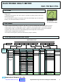
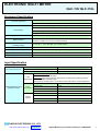
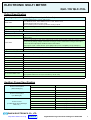
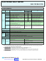
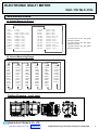
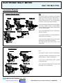
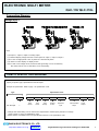
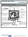
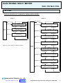
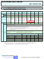
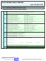
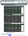
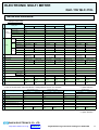
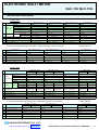
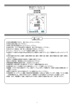
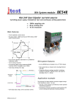
PRODUCT CATALOG
ELECTRONIC MULTI METER
QLC-110/ QLC-110L
ELECTRONIC MULTI METER
QLC-110/ QLC-110L
OUTLINE
* Most suitable for measuring the monitor of incoming circuit from low-voltage circuit to highvoltage circuit.
* Centralized monitoring in line with system is possible by adding analog output and
communication output .
* For oversea sales, the lineup of the product make with phase display sign R-Y-B-W (Hard
model C), U-V-W-N (Hard model D) is carried out.
QLC-110/ 110L
110*110*121mm (600g)
FEATURES
* This is a change measurement for V(RS, ST, TR)/ A(R, S, T)/ W/ var/ cosφ/ Hz/ Wh/ varh in three phase circuit use.
* Analog output 3 circuits or analog output 2 circuits + watthour or var-hour pulse output 1 circuit can be extracted.
* Communication output or communication output + watthour or var-hour pulse output 1 circuit can be extracted.
* Integrated value of Wh/ varh can be expanded displayed until 3rd digit after the decimal point.
* Analog output is equipped with minimum limit.
* Var/ cosφ can be changed to power flow measurement. (output 2 quadrant)
TYPE AND SPECIFICATION CODE
Specification Code
Type
QLC-110
No backlight
QLC-110L
With Backlight
―
(2) Hard model
(2)
(3)
(3) Input circuit
(4)
(5)
1
1Ф 2W
2
1Φ 3W
1
150V, 5A
1
150-300V, 5A
C
R-Y-B-W
Display
3
3Φ 3W
2
150V, 1A
2
150-300V, 1A
4
3Φ 4W
3
300V,5A
5
5A
D
U-V-W-N
Display
4
300V, 1A
6
1A
5
5A
9
6
1A
Z
7
5A (3Φ 3W 3CT)
8
1A (3Φ 3W 3CT)
1
150V/ √3, 5A
9
150V
2
150V/ √3, 1A
* Hard model
C is applied to
QLC-110L
only
1Φ 2W, 3Φ 3W
A
300V
1Φ 3W
None
1
Dis play
change
4-20m A
0-1m A
150-300V
3
1-5V
Except above
4
0-5V
5
0-10V
A
Protocol A (RS-485)
Z
Analog output:
Except above
1
AC85 - 253V
DC80 - 143V
For both use
2
DC20-56V
3Φ 4W
3
300V/ √3, 5A
4
300V/ √3, 1A
1A
150V/ √3
300V, 1A
A
(3Φ 3W 2VT 3CT)
300V/ √3
Z
(7) Analog/
comm unication output
2
300V, 5A
R
9
(3Φ 3W 2VT 3CT)
Except above
0
0
1
5A
Z Except above Z
(6) External
operation input
(8)
No analog/
comm unication
output
150V, 1A
Q
6
(3Φ3 W 2VT 3CT)
S
(7)
0
150V, 5A
5
(3Φ 3W 2VT 3CT)
P
―
(5) Auxiliary power
(4) Input range
R-S-T-N
Display
B
(6)
Except above
Z
Except above
Z Except above
(8) Puls e output
0
None
1 output a
1 contact (photo
MOS relay)
Z
Except above
DAIICHI ELECTRONICS CO., LTD
http://www.daiichi-ele.co.jp
Product List
Digital Measuring Instrument Catalogue e-FB98-098a
2
ELECTRONIC MULTI METER
QLC-110/ QLC-110L
Equipment Specification
Connecting System
Input, Auxiliary Power, M4 Screw
Output, Display Change Input, M3 Screw
Main m onitor: Character height 10m m
LCD Display
5 digits
Sub-m onitor (L): Character height 6mm
4 digits
Sub-m onitor (R): Character height 6m m
4 digits
Bar graph: 30 dots
Display Renewal Tim e
Approx. 1 sec. (Bar graph: Approx. 0.25sec.)
Voltage, Current, Power, Reactive Power, Power Factor,
Frequency, Watt-hour, Var-hour Display Change
Measurem ent
Operating Tem perature/
Humidity Range
Storage Tem perature Range
Material
-10 to +55°C, 30 to 85%RH (No condensation)
-25 to +70°C
ABS (V-0)
Mass
Exterior color: Black (Munsell N1.5)
600g
Size
Refer to outline drawing (Com patible with wide angle indicating instrum ent)
Input Specification
Input Consumption VA
Voltage circuit rated value: 110V (FS: 150V)
0.25VA or less
Voltage circuit rated value: 220V (FS: 300V)
0.5VA or less
Current circuit: 5A, 1A
0.1VA or less
Indication change input: Indication change is possible by adding a voltage signal,
function same as a DISPLAY switch.
Input
Reset input: Reset of the maximum value (minimum value) and an warning output is
Specification
possible by adding a voltage signal.
Rating same as auxiliar power , The smallest pulse width 300ms continual applicable.
AC, DC100/ 110V
External Operation Input
(Display Change)
AC200V/ 220V
Power
Consumption DC24V
Contact
Capacity
0.4VA, 0.4W
1.4VA
0.3W
DC48V
1.2W
AC, DC100/ 110V
3mA
AC200V/ 220V
6mA
DC24V
10mA
DC48V
20mA
DAIICHI ELECTRONICS CO., LTD
http://www.daiichi-ele.co.jp
Product List
Digital Measuring Instrument Catalogue e-FB98-098a
3
ELECTRONIC MULTI METER
QLC-110/ QLC-110L
Output Specification
* Analog output: 3 circuits (with pulse output: 2 circuits)
Rated value
4-20m A: 55Ω or les s , 0-1m A: 10Ω or les s ,
1-5V: 600Ω or m ore, 0-5V: 600Ω or m ore, 0-10V: 2kΩ or m ore
Specify identical value for each circuit.
Non-ins ulation (m inus com m on) between analog outputs
Ripple output
1% p-p or les s agains t output s pan
Res pons e tim e
1s ec. or les s . Tim e to be within ±1 % of final cons tant value
* Pulse output: Output element: watt-hour or var-hour
Output s ys tem
Photo MOS/ FET relay
Contact capacity
AC, DC125V 70m A (Res is tance load, Inductive load)
1a contact
250m s ±10%
Puls e width
When the output puls e cycle at the rated electric power becom es the s peed of 2 puls es or m ore
per s econd by s etting voltage m eas urem ent range, current m eas urem ent range, and output
puls e unite, the output puls e width becom es 100-130m s .
Output puls e cycle = Rated electric power[kW]/ output puls e unite[kWh/ puls e]/ 3600[s ec.]
Output ON res is tance
10Ω or les s
Refer to p.11 for s etting output puls e unit.
* Communication output
Com m unication s ys tem
RS-485 Half-duplex 2-wire s ys tem
Trans m is s ion s peed
1200/ 2400/ 4800/ 9600 bps
Trans m is s ion code
NRZ
Start bit
1 bit
Data bits
7/8 bits
Parity
None/ even/ odd
Stop bit
1/2 bit
As ynchronous com m unication
Cable length
1000m (Fully extended)
Addres s
1-99
No .of connectable units
Connectable up to 31 units .
Us e repeater after 32nd unit (Connectable up to 99 units )
Trans m is s ion character
ASCII code
Auxiliary Power Specification
Power Cons um ption
( With Backlight )
Power Cons um ption
( No Backlight )
Rus h Current
( For Backlight & No Backlight
both us e )
AC85-253V 50/60Hz
10VA
DC80-143V
5W
DC20-56V
6W
AC85-253V 50/60Hz
8VA
DC80-143V
4W
DC20-56V
5W
AC110V
5.3A or les s (Approx. 1.6m s )
AC220V
10.5A or les s (Approx. 1.6m s )
DC110V
3.7A or les s (Approx. 1.6m s )
DC24V
5.0A or les s (Approx. 2.0m s )
DC48V
9.9A or les s (Approx. 2.0m s )
DAIICHI ELECTRONICS CO., LTD
http://www.daiichi-ele.co.jp
Product List
Digital Measuring Instrument Catalogue e-FB98-098a
4
ELECTRONIC MULTI METER
QLC-110/ QLC-110L
PERFORMANCE
Meas uring
elem ent
Item
Approved s tandard
Allowance *(1)
Meas uring range/ Dis play s pecification
Note
Dis play
Output
JIS C 1102-1,-2, -3, -4, -5, -7, JIS C 1111, JIS C 1216, JIS C 1263 perform ance conform ity, EIA s tandard RS-485
Voltage
AC150 - 750.0kV (24 range)
±1.0%
±0.5%
RS-ST-TR
Current
AC5.00A - 30.0kA (70 range)
±1.0%
±0.5%
R-S-T Phas e change *(2)
Power
480W - 1000MW Range s election
Max. s cale s etting 40 - 115%
±1.0%
±0.5%
Range of analog output in indication and
independence s etting pos s ibility *(3)
Reactive power
LEAD, LAG 360var - 1000Mvar
Max. s cale s etting 30 - 115%
±1.0%
±0.5%
Power factor
LEAD 0.5 - 1 - LAG 0.5 OR LEAD 0 - 1 - LAG 0
Range s election
±2.0%
±2.0%
Meas uring
Frequency
elem ent
Watt-hour
Var-hour
Bar graph dis play
Range s election
45 - 55Hz OR 55 - 65Hz, 45 - 65Hz
±0.5%
±0.5%
Range s election
Dis play: 5 colum ns integer,
Multiplying factor: Integer of 10 tim es , enlargem ent
Power factor 1 : ±2.0%
indicatory pos s ibility to 3 integer rank decim al point.
Power factor 0.5 : ±2.5%
Power integratied (receiving),
Integrated value power failure guaranty.
Dis play: 5 colum ns integer,
Multiplying factor: Integer of 10 tim es , enlargem ent
Power factor 0 : ±2.5%
indicatory pos s ibility to 3 integer rank decim al point.
Power factor 0.87 : ±2.5%
LAG reactive power integrated (receiving),
Integrated value power failure guaranty
Bar graph dis play of m ain m onitor elem ent (except watt-hour, var-hour)
Sub-m onitoring elem ents can be dis played by s etting.
Line change *(2)
Range of analog output in indication and
independence s etting pos s ibility
cos Ø = 1 when input is under 20% of
voltage range or being under 2% of current
range (output equal to cos Ø = 1)
0.0Hz when input is under 20% of voltage
range (output lower lim it value -1%)
Norm ally the s etting range of the watt-hour
m eter perform ance conform ity and output
puls e unit (kWh/ puls e) can refer to
com m on s pecification at page 16.
Refer to com m on s pecification page 16 for
s etting range of output puls e unit (kvarh/
puls e)
Bar graph dis play accuracy ±5% (% agains t s pan)
Influence of tem perature
23°C±10°C within allowance
Indicatory renewal tim e
Approx. 1s ec. (Bar graph: Approx. 0.25 s ec.)
Indicatory
s etting
pos s ible
elem ent
Main m onitor
Voltage, current, power, reactive power, power factor, frequency, watt-hour, var-hour
Sub-m onitor (L) Voltage, current, power, reactive power, frequency
Sub-m onitor (R) Voltage, current, power, power factor, frequency
Bar graph
Voltage, current, power, reactive power, power factor, frequency
Option
Analog output (2 circuits when with puls e output, 3 circuits with no with puls e output)
OR com m unication output, puls e output, dis play change input
Power failure guaranty
Setting value/ integrating value
Three phas e 3 wire
Analog
output
(option)
Output pos s ible Three phas e 4 wire
elem ent
Single phas e
Single phas e 3 wire
Voltage (RS-ST-TR), Current (R-S-T), Power, Reactive power, Power
factor, Frequency
Voltage (RN-SN-TN-RS-ST-TR), Current (R-S-T), Power, Reactive
power, Power factor, Frequency
Voltage, Current, Power, Reactive power, Power factor, Frequency
Voltage (RN-TN-RT), Current (R-T-N), Power, Reactive power, Power
factor, Frequency
*(1) Due to the measurement system of the meter, the accuracy will decrease when output of the control of recycling, SCR phase
control and PWM control invertor is measured directly.
*(2) Three phase 4 wire: Voltage display: RN-SN-TN-RS-ST-TR, Current display: R-S-T-N,
Bar graph full scale = Full scale value of line voltage, voltage balance type.
Single phase 3 wire: Voltage display: RN-TN-RT, Current display R-T-N, Full scale value of bar graph: 300V
*(3) Reverse power can be measured up to -15% of full scale by digital meter at bar graph 1/2 peak-peak setting.
DAIICHI ELECTRONICS CO., LTD
http://www.daiichi-ele.co.jp
Product List
Digital Measuring Instrument Catalogue e-FB98-098a
5
ELECTRONIC MULTI METER
QLC-110/ QLC-110L
MEASURING RANGE
A) Voltage Measuring Range
150V
150.0V
300V
300.0V
600V
1500V
3000V
3.00k V
4500V
4.50k V
9000V
9.00k V
(1 1 0 V )
(1 1 0 V )
(2 2 0 V , 2 2 0 V / 1 1 0 V )
(2 2 0 V , 2 2 0 V / 1 1 0 V )
(4 4 0 V / 1 1 0 V )
(1 1 0 0 V / 1 1 0 V )
(2 2 0 0 V / 1 1 0 V )
(2 2 0 0 V / 1 1 0 V )
(3 3 0 0 V / 1 1 0 V )
(3 3 0 0 V / 1 1 0 V )
(6 6 0 0 V / 1 1 0 V )
(6 6 0 0 V / 1 1 0 V )
15.00k V
30.0k V
45.0k V
90.0k V
105.0k V
150.0k V
180.0k V
210.0k V
255.0k V
300.0k V
375.0k V
750.0k V
(1 1 k V / 1 1 0 V )
(2 2 k V / 1 1 0 V )
(3 3 k V / 1 1 0 V )
(6 6 k V / 1 1 0 V )
(7 7 k V / 1 1 0 V ) * (4 )
(1 1 0 k V / 1 1 0 V )
(1 3 2 k V / 1 1 0 V )
(1 5 4 k V / 1 1 0 V )
(1 8 7 k V / 1 1 0 V ) * (5 )
(2 2 0 k V / 1 1 0 V )
(2 7 5 k V / 1 1 0 V ) * (6 )
(5 5 0 k V / 1 1 0 V )
*(4) Full scale in the bar graph
becomes 120.0kV
*(5) Full scale in the bar graph
becomes 270.0kV
*(6) Full scale in the bar graph
becomes 400.0kV
B) Current Measuring Range
5.00A
6.00A
7.50A
8.00A
10.00A
10.0A
12.00A
12.0A
15.00A
15.0A
20.00A
20.0A
25.00A
25.0A
30.00A
30.0A
40.0A
50.0A
60.0A
75.0A
80.0A
100.0A
100A
120.0A
120A
150.0A
150A
200.0A
200A
250.0A
250A
300.0A
300A
400A
500A
600A
750A
800A
1000A
1.00kA
1200A
1.20kA
1500A
1.50kA
2000A
2.00kA
2500A
2.50kA
3000A
3.00kA
4000A
4.00kA
5000A
5.00kA
6000A
6.00kA
7500A
7.50kA
8000A
8.00kA
10.00kA
10.0kA
12.00kA
12.0kA
15.00kA
15.0kA
20.00kA
20.0kA
30.00kA
30.0kA
Outline Drawing (unit: mm)
DAIICHI ELECTRONICS CO., LTD
http://www.daiichi-ele.co.jp
Product List
Digital Measuring Instrument Catalogue e-FB98-098a
6
ELECTRONIC MULTI METER
QLC-110/ QLC-110L
Connection Diagram
Voltage/ Current Input (11)
Note:
*(7) Output 1, output 2 are exclusive use for analog
output and output 3 becomes analog output or
pulse output. [In case output 3 is anolog output,
output 3 will becomes 17(+), 18( -).] Pulse output
is watt hour and var hour output of output 3.
*(8) External display change becomes each option
for output 1, output 2, output 3, communication
output, pulse output. Pulse output is watt hour and
Var hour output of output.
*(9) In case of single phase 3 wire: S-phase No.7
becomes N-phase.
*(10) Terminal resistance is connected interior by
short circuit No.14 and No.16.
*(11) In case of low voltage circuit, the second side
grounding of VT and CT is unnecessary.
Also when used in 110V or 220V direct, VT is
unnecessary.
Current Input (15)
Note:
*(12) Output 1, output 2, output 3 is analog output
*(13) External display change becomes of each
option for output 1, output 2, and output 3.
*(14) In case of single phase 3 wire, S phase
becomes N phase.
*(15) In case of low voltage circuit, the second side
grounding of CT is unnecessary.
DAIICHI ELECTRONICS CO., LTD
http://www.daiichi-ele.co.jp
Product List
Digital Measuring Instrument Catalogue e-FB98-098a
7
ELECTRONIC MULTI METER
QLC-110/ QLC-110L
Connection Diagram
Voltage Input (20)
Note:
* (16) Output 1, output 2, output 3 is analog output.
* (17) External display change becomes of each option for output 1, output 2, output 3.
* (18) In case of single phase 3 wire, S phase No.7 becomes N phase.
* (19) There is no line display on display screen.
* (20) In case of low voltage circuit, the second side grounding of VT is unnecessary.
Also when used in 110V or 200V direct, VT is unnecessary.
ITEM TO SPECIFY ON PURCHASE
Specify for product type, specification and units require.
Example of specification. Refer to page 1 for specification code.
Type
Specification Code
QLC - 110
L
No Backlight
↑
Blank
With Backlight
L
―
B
3
3
1
1
↑
↑
↑
↑
Hard
Model
Input
Circuit
Input
Range
Auxiliary
Power
↑
External
Operation
Input
―
1
1
↑
Analog /
Communication
output
↑
0
Pulse
Output
* Change from initial setting can be receive with compensation. Please specify the items of change.
Refer to page 14 and 15 for initialization value.
* Please have a consultation with us for specification which is not in specification code.
DAIICHI ELECTRONICS CO., LTD
http://www.daiichi-ele.co.jp
Product List
Digital Measuring Instrument Catalogue e-FB98-098a
8
ELECTRONIC MULTI METER
QLC-110/ QLC-110L
NAME AND THE FUNCTION OF EACH PART
Digital Display
3 elements can be measured and monitored concurrently.
Sub-monitor (L)
Main monitor
Sub-monitor (R)
Bar Graph Display
The measurement value of the main
monitor is indicated by analog.
(Also the setting which measurement
value of sub-monitor display by bar
graph is possible.)
Scale Numbering
This is set automatically by
measuring range setting.
Multiplying Factor Display
Watt hour and var hour display will
be display at the upper right side
of main monitor.
SET
This is a setting mode switch. With
continual ON of 3 seconds or more,
display mode become setting mode.
This switch also used to determine
setting value in the setting mode.
Flicker Setting Index
Can use it for a management index
by flicker OFF setting.
Unit Display
-
This is set automatically by
measuring range setting.
This switch used to confirm current
flicker value, voltage flicker value, and
power flicker value. Operation mode
will returns back to display mode with
non operation for 10 seconds. In setting
mode, it is used to carry down the
setting value.
+
This is the switch which changes the measuring
elements of the main monitor. It can replace with the
DISPLAY switch functionally by setting. In setting
mode, it is used for carry up the setting value. It will
returns back to original display pattern with non
operation for 10 minutes.
SHIFT
This switch used when expanding the
integrated value Wh and varh. It can
expand to 3 digit after decimal point.
DISPLAY
Used it when changing the switch current
(voltage) phases (lines). Can replace with
the + switch functionally by setting. Setting
mode will returns back to display mode after
1 action. It will returns back to original set up
display pattern with non operation for 10
minutes.
DAIICHI ELECTRONICS CO., LTD
http://www.daiichi-ele.co.jp
Product List
Digital Measuring Instrument Catalogue e-FB98-098a
9
ELECTRONIC MULTI METER
QLC-110/ QLC-110L
SETTING
Refer to attached user's manual for setting method details.
Setting - 1
Setting - 2
SET and SHIFT
SET 3s
DISPLAY
3s
111-115
Display combination setting
SHIFT and +
DISPLAY
211-214 Measurement range setting
(V, A, cosφ, Hz)
SHIFT and -
SHIFT and +
Display
mode
DISPLAY
121-128
Flicker value setting
DISPLAY
SHIFT and +
DISPLAY
SHIFT and -
SHIFT and +
221-224A
W, var measurement/output range setting
SHIFT and +
131 DISPLAY switch function
change setting
DISPLAY
SHIFT and -
Refer to pg. 13 for display combination (pattern).
DISPLAY
SHIFT and -
271∼278
Measurement display ON/OFF setting
SHIFT and +
DISPLAY
SHIFT and -
261∼262 Special item setting
(Display dead band/power flow measurement)
SHIFT and +
DISPLAY
SHIFT and -
251P
Wh(varh) pulse output setting
SHIFT and +
DISPLAY
SHIFT and -
241A
Analog output, low input cut setting
SHIFT and +
Display
mode
SHIFT and -
231A-233A/P
Output element setting
SHIFT and +
DISPLAY
SHIFT and -
SHIFT and -
281
Return to initial set value
SHIFT and +
SHIFT and -
DAIICHI ELECTRONICS CO., LTD
http://www.daiichi-ele.co.jp
Product List
Digital Measuring Instrument Catalogue e-FB98-098a
10
ELECTRONIC MULTI METER
QLC-110/ QLC-110L
LC-110 SERIES COMMON SPECIFICATION
Approved Standard/ Pulse Output/ Intensity
Type
Electronic
Electronic three
overload/ leakage
phas e current
detection m eter
m eter
relay
Electronic m ulti
m eter
Electronic
harm onics
m eter relay
Electronic
dem and m ulti
m eter
Electronic
m ax./ m in.
m ulti m eter
No
backlight
QLC-110
HLC-110
DLC-110
MLC-110
LLC-110
W ith
backlight
QLC-110L
HLC-110L
DLC-110L
MLC-110L
JIS C 1102
-1, -2, -3, -5, -7
JIS C 1111
JIS C 1216
Perform ance
conform ed
EIA s tandard
RS-485
Watt-hour
Item
Approved standard
Output
element
JIS C 1102
JIS C 1102
-1, -2, -3, -4, -5, -7
-1, -2, -7
JIS C 1111
JIS C 1111
JIS C 1216
Perform ance
JIS C 1263
conform ed
Perform ance
conform ed
EIA s tandard
RS-485
Watt-hour or
var-hour
-
*Output s ys tem : Photo MOS - FET relay 1 a contact.
Output ON res is tance: 10Ω or les s .
Electronic
three phas e
voltage m eter
Electronic
DC receiving
m eter
Electronic
DC input m eter
ALC-110
VLC-110
XLC-110
TLC-110
LLC-110L
ALC-110L
VLC-110L
XLC-110L
TLC-110L
JIS C 1102
-1, -2, -7
JIS C 1111
Perform ance
conform ed
EIA s tandard
RS-485
JIS C 1102
-1, -2, -7
JIS C 1111
JIS C 8325
JIS C 8374
JIS C 1216
Perform ance
conform ed
JIS C 1102
-1, -2, -7
JIS C 1111
Perform ance
conform ed
JIS C 1102
-1, -2, -7
JIS C 1111
Perform ance
conform ed
JIS C 1102
-1, -2, -7, -9
JIS C 1111
JIS C 1010-1
Perform ance
conform ed
EIA s tandard
RS-485
JIS C 1102
-1, -2, -7, -8, -9
JIS C 1111
JIS C 1010-1
Perform ance
conform ed
EIA s tandard
RS-485
-
Watt-hour
-
-
-
Discontinued Model
(since December 31,2011).
-
Contact capacity: AC, DC125V 70m A (res is tance load, inductive load)
*Puls e width: 250m s ±10% (There is a cas e of 100-130m s by range s etting.)
When the output puls e cycle at the rated electric power becom es the s peed of 2 puls es or m ore per s econd by s etting voltage m eas urem ent range,
current m eas urem ent range, and output puls e unit, the output puls e width becom es 100 - 130m s .
*Output puls e cycle = Rated electric power [kW] / output puls e unit [kWh / puls e] / 3600 [s ec.]
For exam ple: when voltage m eas urem ent range: 9000V (6600V / 110V), current range: 80.0A (80A / 5A), output puls e unit: 0.1 kWh / puls e
rated electric power = 1kW × (6600 / 110V) × (80 / 5A) = 960 [kW]
output puls e cycle = 960 [kW] / 0.1 [kWh / puls e] / 3600 [s ec.] = 2.667 puls e / s ec.
puls e width becom es 100 - 130m s .
*Output puls e unit can be s et in following range. Output puls e unit is not changed by changing m eas uring range.
Pulse
output
Outout
pulse
constant
Three phas e 3 wire / Three phas e 4 wire: Full load power (kW, kvar) = √ 3 × rated voltage (V) × rated current (A) × 10 -3
Single phas e 3 wire
: Full load power (kW, kvar) = 2 × rated voltage (V) × rated current (A) × 10 -3
Single phas e
: Full load power (kW, kvar) = Rated voltage (V) × rated current (A) × 10 -3
Full load power (kW, kvar)
Below1
1 or m ore
Below 10
10 or m ore
Below 100
100 or m ore
Below 1000
1,000 or m ore
Below 10,000
10,000 or m ore
Below 100,000
100,000 or m ore
Below 1,000,000
Multiplying
factor
Output puls e unit kWh (kvarh) / puls e
0.1
0.01
0.001
0.0001
1
0.1
0.01
0.001
10
1
0.1
0.01
100
10
1
0.1
1,000
100
10
1
10,000
1,000
100
10
100,000
10,000
1,000
100
0.01 *(1)
0.1
1
10
100
1,000
10,000
(1) Applied only for DLC-110 / 110L. Even though multiplying factor is 0.01, multiplying factor display is 0.1
(integer digit: 4 digits display Expansion display: 4 digits after decimal point.)
DAIICHI ELECTRONICS CO., LTD
http://www.daiichi-ele.co.jp
Product List
Digital Measuring Instrument Catalogue e-FB98-098a
11
ELECTRONIC MULTI METER
QLC-110/ QLC-110L
LC-110 SERIES COMMON SPECIFICATION
Approved Standard/ Pulse Output/ Intensity
(1) Voltage circuit: 2 tim es of rated voltage (10s ec.)
Overload
capacity
1.2 tim es (continuity)
(2) Current circuit: 40 tim es of rated current (1 s ec.), 20 tim es (4 s ec.), 10 tim es ( 16 s ec.), 1.2 tim es (continuity)
(3) Auxiliary power: 1.5 tim es of rated voltage (10 s ec.), 1.2 tim es (continuity), 1.5 tim es of rated voltage at DC 100/ 110 (10 s ec.), 1.3 tim es (continuity)
(4) DC input circuit (4 to 20m A): 10 tim es of rated current (5 s ec.), 1.2 tim es (continuity)
(1) Between electrical s ys tem and cas e (ground)
D C500V 50MΩ or m ore
(2) Between input, output and auxiliary power
D C500V 50MΩ or m ore
(3) Between analog output and puls e output
D C500V 50MΩ or m ore (QLC, DLC , LLC )
(4) Between analog output and alarm output
D C500V 50MΩ or m ore (HLC, DLC , MLC, LLC)
(5) Between com m unication output and puls e output
Ins ulation
(6) Between com m unication output and alarm output
res is tance
(7) Between puls e output and alarm output
D C500V 50MΩ or m ore (QLC, D LC )
D C500V 50MΩ or m ore (DLC,MLC )
D C500V 50MΩ or m ore (DLC,LLC)
(8) Between alarm output 1 and alarm output 2
D C500V 50MΩ or m ore (HLC,LLC)
(9) Between D C input (4 to 20m A), AC input and auxiliary pow er
D C500V 50MΩ or m ore (QLC w ith DC input)
(10) Betw een DC inputs
D C500V 50MΩ or m ore (XLC ,TLC)
(11) Non-ins ulation by m inus com m on betw een analog outputs .
(QLC, DLC, H LC , XLC, TLC, MLC)
(1) Between electrical s ys tem and cas e (ground)
AC2000V 50/ 60 Hz
1 m in.
(2) Between input, ouutput and auxiliary pow er
AC2000V 50/ 60 Hz
1 m in.
(3) Between analog output and puls e output
AC1500V 50/ 60 Hz
1 m in. (QLC, D LC , LLC)
(4) Between analog output and alarm output
AC1500V 50/ 60 Hz
1 m in. (HLC , D LC, MLC, LLC)
(5) Between com m unication output and puls e output
AC1500V
50/ 60 Hz
1 m in. (QLC , D LC)
AC1500V
50/ 60 Hz
1 m in. (D LC , MLC)
AC1500V
50/ 60 Hz
1 m in. (D LC , LLC)
Withs tand
(6) Between com m unication output and alarm output
voltage
(7) Between puls e output and alarm output
Strength
Lightning
im puls e
withs tand
voltage
N ois e
capacity
(8) Between alarm output 1 and alarm output 2
AC1500V
50/ 60 Hz
1 m in. (H LC , LLC)
(9) Between D C input (4 to 20m A), AC input and auxiliary pow er
AC2000V
50/ 60 Hz
1 m in. (QLC w ith DC input)
(10) Betw een DC inputs
AC2000V
50/ 60 Hz
1 m in. (XLC , TLC )
(11) Non-ins ulation by m inus com m on betw een analog outputs .
(QLC, DLC, H LC , XLC, TLC, MLC)
(1) Between electrical s ys tem (analog output/ com m unication output excluded) and ground
6kV 1.2/ 50µs pos itive/ negative polarity
3 tim es for each (QLC, DLC)
(2) Between electrical s ys tem (DC input 4 to 20m A excluded) and ground
5kV 1.2/ 50µs pos itive/ negative polarity
3 tim es for each
(3) Between analog output or com m unication output and ground
5kV 1.2/ 50µs pos itive/ negative polarity
3 tim es for each (QLC,D LC)
(4) Between auxiliary power and ground
7kV 1.2/ 50µs pos itive/ negative polarity
3 tim es for each (LLC )
(1) Os cillatory s urge voltage
1 to 1.5MHz peak voltage: When attenuated os cillatory waveform (2.5 to 3kV) is applied repeatedly:
Meas ured error: within 10% (power circuit, AC voltage circuit, AC current circuit,
XLC, TLC: D C voltage/ current circuit)
N o com m unication error/ com m unication halt
(2) Square-wave im puls e nois e
N ois e (1µS, 100ns w idth) is repeatedly applied for 5 m in. : Meas ured error is within 10%
AC voltage/ AC current circuit (norm al/ com m on) 1.5 kV or m ore
Power circuit (norm al/ com m on)
1.5 kV or m ore
Puls e output (com m on)
1.0 kV or m ore
Alarm output (com m on)
1.0 kV or m ore
Operation input (com m on)
1.0 kV or m ore
Analog output (Inductive)
1.0 kV or m ore
C om m unication output (Inductive)
1.0kV or m ore
(3) Radio nois e: When radion w ave (150, 400, 900MH z) is applied (5W, 1m ) interm ittently: Meas ured error is within 10%
(4) Electros tatic nois e: At the pas s age of electric current 8kV Meas ured error : w ithin 10%
At no pas s age of electric current 10kV: No dam age (condens er charge s ys tem )
N ote: There are s om e cas es that s om e item can not be applied for particular m odel. Refer to type and s pecification code.
Vibration/
s hock
Vibration: 1/ 2 peak-peak: 0.15m m
Shock: 490m /s ²
10 to 55H z
1 octave/ m in.
5 tim es s w eep
3 tim es for each direction.
DAIICHI ELECTRONICS CO., LTD
http://www.daiichi-ele.co.jp
Product List
Digital Measuring Instrument Catalogue e-FB98-098a
12
ELECTRONIC MULTI METER
QLC-110/ QLC-110L
DISPLAY COMBINATION (PATTERN)
1. Three phase 3 wire/ Three phase 4 wire (voltage/ current input)
N o.
Pa tte rn N O.
Ma in m o n ito r
Su b -m o n ito r (L )
Su b -m o n ito r (R )
Ba r g ra p h
N o te
1
Pa tte rn 1
A(S)
V(R S)
W
A(S )
S ta n d a rd
2
Pa tte rn 2
W
V(R S)
A(S)
W
3
Pa tte rn 3
Wh
V(R S)
A(S)
A(S )
4
Pa tte rn 4
Wh
A(S )
W
A(S )
5
Pa tte rn 5
Wh
A(S )
W
W
6
Pa tte rn 6
A(S)
V(R S)
Hz
A(S )
7
Pa tte rn 7
A(S)
V(R S)
-
A(S )
8
Pa tte rn 8
V(R S)
V(ST)
V(TR )
V(R S )
9
Pa tte rn 9
A(S)
A(R )
A(T)
A(S )
A
Pa tte rn A
V(R S)
-
Hz
V(R S )
B
Pa tte rn B
co s Φ
A(S )
W
W
C
Pa tte rn C
co s Φ
V(R S)
Hz
co s Φ
D
Pa tte rn D
co s Φ
-
Hz
co s Φ
E
Pa tte rn E
va r
A(S )
W
W
F
Pa tte rn F
Wh
W
co s Φ
W
G
Pa tte rn G
W
va r
co s Φ
W
S p e cifica tio n
2. Single phase 3 wire (voltage/ current input)
N o.
P a tte rn N O .
Ma in m o n ito r
S u b -m o n ito r (L )
S u b -m o n ito r (R )
B a r g ra p h
N o te
1
P a tte rn 1
A(R )
V(R N )
W
A(R )
S ta n d a rd
2
P a tte rn 2
W
V(R N )
A(R )
W
3
P a tte rn 3
Wh
V(R N )
A(R )
A(R )
4
P a tte rn 4
Wh
A(R )
W
A(R )
5
P a tte rn 5
Wh
A(R )
W
W
6
P a tte rn 6
A(R )
V(R N )
Hz
A(R )
7
P a tte rn 7
A(R )
V(R N )
-
A(R )
8
P a tte rn 8
V(R N )
V(TN )
V(R T)
V(R N )
9
P a tte rn 9
A(R )
A(T)
A(N )
A(R )
A
P a tte rn A
V(R N )
-
Hz
V(R N )
B
P a tte rn B
co s Φ
A(R )
W
W
C
P a tte rn C
co s Φ
V(R N )
Hz
co s Φ
D
P a tte rn D
co s Φ
-
Hz
co s Φ
E
P a tte rn E
va r
A(R )
W
W
F
P a tte rn F
Wh
W
co s Φ
W
G
P a tte rn G
W
va r
co s Φ
W
S p e cifica tio n
3. Single phase (voltage/ current input)
N o.
Pa tte rn N O.
Ma in m o n ito r
Su b -m o n ito r (L )
Su b -m o n ito r (R )
Ba r g ra p h
N o te
1
Pa tte rn 1
A
V
W
A
S ta n d a rd
2
Pa tte rn 2
W
V
A
W
3
Pa tte rn 3
Wh
V
A
A
4
Pa tte rn 4
Wh
A
W
A
5
Pa tte rn 5
Wh
A
W
W
6
Pa tte rn 6
A
V
Hz
A
7
Pa tte rn 7
A
V
-
A
8
Pa tte rn 8
V
-
0
V
9
Pa tte rn 9
A
-
-
A
A
Pa tte rn A
V
-
Hz
V
B
Pa tte rn B
co s Φ
A
W
W
C
Pa tte rn C
co s Φ
V
Hz
co s Φ
D
Pa tte rn D
co s Φ
-
Hz
co s Φ
E
Pa tte rn E
va r
A
W
W
F
Pa tte rn F
Wh
W
co s Φ
W
G
Pa tte rn G
W
va r
co s Φ
W
S p e cifica tio n
Combination beyond above-mentioned pattern can be set with front switch.
Note: (1) Voltage input product: Only pattern 8 & A
(2) Current input product: Only pattern 9
DAIICHI ELECTRONICS CO., LTD
http://www.daiichi-ele.co.jp
Product List
Digital Measuring Instrument Catalogue e-FB98-098a
13
ELECTRONIC MULTI METER
QLC-110/ QLC-110L
INITIALIZATION VALUE
1. Voltage/ Current Input
Three phase 3 wire
Single phas e
Single phase 3 wire
110V input
Pattern
1
Three phas e 4 wire
Setting item
No.
Main monitor
Display
Sub-m onitor (L)
combination
Sub-m onitor (R)
Bar graph
Upper lim it
110/ √3V input
220V input
220/ √3V input
110V input
Pattern 1
Pattern 1
Pattern 1
pattern 1
A(S)
A(S)
A(R)
A
V(RS)
V(RS)
V(RN)
V
W
W
W
W
A(S)
A(S)
A(R)
A
100.0A (/5A)
1500A (/5A)
500A (/5A)
50.0A (/5A)
OFF
OFF
OFF
220V input
Current
Flicker ON/ OFF OFF
Upper lim it
Voltage Lower lim it
2
7260V (/121V)
242V
440V (/110V)
220V
110.0V
3630V (/121V)
242V
5940V (/99V)
198V
360V (/90V)
180V
90.0V
2970V (/99V)
198V
OFF
OFF
Flicker
Flicker ON/ OFF OFF
Power
OFF
Upper lim it
1200kW (/1kW)
40.0kW (/2kW)
1200kW (/1kW)
600kW (/2kW)
100kW (/1kW)
150kW (/500W)
10kW (/1kW)
Lower lim it
-180kW (/-150W)
-6.0kW (/-300W)
-180kW (/-150W)
-90kW (/-300W)
-15kW (/-150W)
-22.5kW (/-75W)
-1.5kW (/-150W)
Flicker ON/ OFF OFF
OFF
OFF
OFF
3
Voltage range
9000V
(6600V/110V)
4
Current range
100.0A (100A/5A)
5
Power range
1200kW (/1kW)
6
Reactive power range
LEAD,LAG600kvar LEAD,LAG20.0kvar LEAD,LAG600kvar LEAD,LAG300kvar LEAD,LAG50.0kvar
(/500var)
(/1kvar)
(/500var)
(/1kvar)
(/500var)
7
Power factor range
LEAD0.5 - 1 - LAG0.5
LEAD0.5 - 1 - LAG0.5
LEAD0.5 - 1 - LAG0.5 LEAD0.5 - 1 - LAG0.5
8
Frequency range
45 - 65Hz
45 - 65Hz
45 - 65Hz
45 - 65Hz
9
Output 1 elem ent *1
Analog output: A(S)
Analog output: A(S)
Analog output: A(R)
Analog output: A
Analog output: V(RS)
Analog output: V(RS)
Analog output: V(RN) Analog output: V
10 Output 2 elem ent *1
11 Output 3 elem ent *1
300V (220V direct) 600V (440V/110V) 300V (220V direct) 150.0V (100-200V)
1500A (1500A/5A)
40.0kW (/2kW)
1200kW (/1kW)
600kW (/2kW)
4500V
(3300V/110V)
500A (500A/5A)
50.0A (50A/5A)
100.0kW (/1kW)
150.0kW (/500W)
W
W
W
Pulse output
Wh
Wh
Wh
Wh
100kW (/1kW)
150kW (/500W)
1200kW (/1kW)
40.0kW (/2kW)
1200kW (/1kW)
600kW (/2kW)
LEAD,LAG600kvar LEAD,LAG20.0kvar LEAD,LAG600kvar LEAD,LAG300kvar LEAD,LAG50.0kvar
13 Reactive power analog output range *1
(/500var)
(/1kvar)
(/500var)
(/1kvar)
(/500var)
10kWh (kvarh)/
Pulse
14 Output pulse unit *1
0.1kWh (kvarh)/
puls e
10kWh (kvarh)/
pulse
1kWh (kvarh)/
pulse
1kWh (kvarh)/ pulse
W
9
Three phas e 3 wire
Setting item
110V input
220V input
Three phas e 4 wire
110/ √ 3V input
220/ √ 3V input
1kWh (kvarh)/ pulse
Single phas e
Single phas e 3 wire
110V input
1
1
1
10 Trans m is s ion s peed
9600bps
9600bps
9600bps
9600bps
11 Data bits
7 bits
7 bits
7 bits
7 bits
12 Parity
Even (E)
Even (E)
Even (E)
Even (E)
13 Stop bit
1
1
1
1
14 Puls e output elem ent *1
Wh
Wh
Wh
Wh
15 Checks um addition range
ETX included
ETX included
ETX included
ETX included
16 Output puls e unit
10kWh (kvarh)/
puls e
1kWh (kvarh)/ puls e
1kWh (kvarh)/
puls e
*1
0.1kWh (kvarh)/
puls e
10kWh (kvarh)/
puls e
1kWh (kvarh)/
puls e
0.1kWh (kvarh)/
pulse
*1 Option selection.
1
Addres s
10.00kW (/1kW)
LEAD,LAG75.0kvar LEAD,LAG5.00kvar
(/250var)
(/500var)
In case of communication output specification: Setting items No.9 to No.14 is as below.
No.
10.00kW (/1kW)
LEAD,LAG75.0kvar LEAD,LAG5.00kvar
(/250var)
(/500var)
Analog output
12 Power analog output range *1
300V (220V direct)
220V input
0.1kWh (kvarh)/
puls e
*1 Option selection.
DAIICHI ELECTRONICS CO., LTD
http://www.daiichi-ele.co.jp
Product List
Digital Measuring Instrument Catalogue e-FB98-098a
14
ELECTRONIC MULTI METER
QLC-110/ QLC-110L
INITIALIZATION VALUE
2. Current input
Se ttin g ite m
No.
Th re e p ha s e 3 w ire
Pa ttern
1
Sing le p h as e
Sin gle p h a s e 3 w ire
Pa ttern 9
Pa tte rn 9
Pa ttern 9
A(S)
A(S)
A(R )
A
A(R )
A(R )
A(T)
-
A(T)
A(T)
A(N )
-
A(S)
A(S)
A(R )
A
U p pe r lim it
1 00 .0 A (/5 A)
1 5 0 0A (/5 A)
5 00 A (/5 A)
5 0 .0 A (/5 A)
Flicke r ON / OFF
OFF
OFF
OFF
OFF
Ma in m o nito r
D is p la y
Su b -m o nitor (L)
co m b in a tio n
Su b -m o nitor (R )
Ba r g ra p h
C u rren t
Th ree p h a s e 4 w ire
Pa tte rn 9
2
Flicke r
3
C urre n t ra ng e
1 00 .0 A (10 0 A/5A)
1 5 0 0A (1 50 0 A/5 A)
5 00 A (50 0 A/5 A)
5 0 .0 A (5 0 A/5A)
4
Outp u t 1 e le m e n t *1
Ana lo g o u tpu t: A(S)
An a lo g o u tp u t: A(S )
Ana lo g o utpu t: A(R )
An a lo g o u tp u t: A
5
Outp u t 2 e le m e n t *1
Ana lo g o u tpu t: A(R )
An a lo g o u tp u t: A(R )
Ana lo g o utpu t: A(T)
-
6
Outp u t 3 e le m e n t *1
Ana lo g o u tpu t: A(T )
An a lo g o u tp u t: A(T )
Ana lo g o utpu t: A(N )
-
In case of communication output specification: Setting items No.4 to No.5 is as below.
Setting item
N o.
Three phas e 3 w ire
Three phas e 4 w ire
*1 Option selection.
Single phas e
Single phas e 3 w ire
4
Addres s
1
1
1
1
5
Trans m is s ion s peed
9600bps
9600bps
9600bps
9600bps
6
D ata bits
7 bits
7 bits
7 bits
7 bits
7
Parity
Even (E)
Even (E)
Even (E)
Even (E)
8
Stop bit
1
1
1
1
9
C hecks um addition range
ETX included
ETX included
ETX included
ETX included
3. Voltage input
No.
Three phas e 3 wire
Setting item
110V input
Pattern
1
Main m onitor
Dis play
Sub-m onitor (L)
com bination
Sub-m onitor (R)
Bar graph
Upper lim it
2
Flicker
Voltage Lower lim it
Three phas e 4 wire
220V input
110/ √3 input
Single phas e
Single phas e 3 wire
220/ √ 3 input
110V input
Pattern8
Pattern8
Pattern8
Pattern8
V(RS)
V(RS)
V(RN)
V
V(ST)
V(ST)
V(TN)
-
V(TR)
V(TR)
V(RT)
-
V(RS)
V(RS)
V(RN)
V
220V input
7260V (/121V)
242V
440V (/110V)
220V
110.0V
3630V (/121V)
242V
5940V (/99V)
198V
360V (/90V)
180V
90.0V
2970V (/99V)
198V
OFF
OFF
Flicker ON/ OFF OFF
9000V
(6600V/ 110V)
45 - 65Hz
OFF
3
Voltage range
300V
(220V direct)
600V
(440V/ 110V)
45 - 65Hz
300V
(220V direct)
4
Frequency range
45 - 65Hz
4500V
(3300V/ 110V)
45 - 65Hz
5
Output 1 elem ent *1
Analog output: V(RS)
Analog output: V(RS)
Analog output: V(RN)
Analog output: V
6
Output 2 elem ent *1
Analog output: V(ST)
Analog output: V(ST)
Analog output: V(TN)
Analog output: Hz
7
Output 3 elem ent *1
Analog output: V(TR)
Analog output: V(TR)
Analog output: V(RT)
-
150.0V (100 - 200V)
In case of communication output specification: Setting items No.5 to No.7 is as below.
No.
Th re e p h a s e 3 w ire
S e ttin g ite m
1 1 0 V in p u t
Th re e p h a s e 4 w ire
1 1 0 / √ 3 V in p u t
2 2 0 V in p u t
*1 Option selection.
S in g le p h a s e
S in g le p h a s e 3 w ire
2 2 0 / √ 3 V in p u t
1 1 0 V in p u t
5
Ad d re s s
1
1
1
1
6
Tra n s m is s io n s p e e d
9600bps
9600bps
9600bps
9600bps
7
D a ta b its
7 b its
7 b its
7 b its
7 b its
8
P a rity
E ve n (E )
E ve n (E )
E ve n (E )
E ve n (E )
9
S to p b it
1
1
1
1
E TX in clu d e d
E TX in clu d e d
E TX in clu d e d
E TX in clu d e d
1 0 C h e cks u m a d d itio n ra n g e
300V
(220V direct)
2 2 0 V in p u t
DAIICHI ELECTRONICS CO., LTD
http://www.daiichi-ele.co.jp
Product List
Digital Measuring Instrument Catalogue e-FB98-098a
15