1
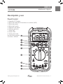
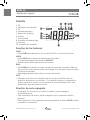
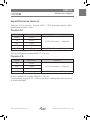
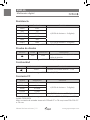
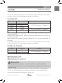
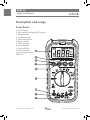
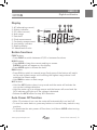
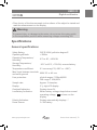
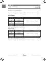
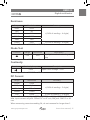
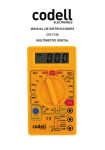
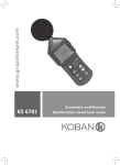
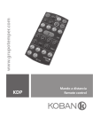
www.grupotemper.com
KMD 05
Multímetro digital
Digital multimeter
KMD 05
Multímetro digital
Índice
Introducción
3
Información de seguridad
3
Descripción y uso
5
Instrucciones de funcionamiento
7
Medición de tensión CA/CC
7
Medición de corriente CA/CC
7
Medición de resistencia
8
Medición de continuidad
8
Prueba de diodos
9
Prueba de baterías
9
Medición de temperatura
9
Especificaciones
10
Mantenimiento
13
Manual de instrucciones | 2
www.grupotemper.com
KMD 05
Multímetro digital
Introducción
Precaución
Con el fin de evitar una descarga eléctrica o daños personales, lea
detenidamente este manual y toda su información de seguridad antes de
utilizar el medidor.
El KMD 05 es un multímetro de pequeñas dimensiones, seguro y fiable
gracias a su pantalla de 3 ½ dígitos con función de escalas automática.
Diseñado para realizar mediciones de Tensión CA/CC, Corriente CA/
CC, resistencia, capacitancia, diodos, continuidad, prueba de baterías,
temperatura y medición de tensión sin contacto. Se trata de un herramienta
ideal tanto para uso por parte de profesionales como aficionados.
Información de seguridad
Recomendaciones generales
El KMD 05 cumple la normativa standard para instalaciones CAT III 600V con
un grado de contaminación de 2.
•La protección suministrada por el instrumento sólo puede ser asegurada si
se cumplen estrictamente todas las instrucciones de seguridad.
•Los símbolos de seguridad del medidor indican situaciones potenciales de
peligro. Tenga precaución cuando realice mediciones próximas a los límites
de seguridad indicados.
•Nunca sobrepase los valores límite para cada rango de medición que se
indican en este manual.
Precauciones
• Siga todas las precauciones de Seguridad contenidas en este manual.
•Compruebe que el medidor está en buen estado antes de usarlo. No lo
utilice si observa algún daño o rotura.
•Revise las puntas de prueba y asegúrese de que no hay ningún cable
expuesto, de ser así , deberá cambiarlas por unas nuevas.
•Asegúrese de que el medidor funciona correctamente probando en
primer lugar una tensión conocida. No lo utilice si nota un funcionamiento
anormal ya que la protección puede estar dañada.
www.grupotemper.com
Manual de instrucciones | 3
KMD 05
Multímetro digital
•Nunca mida tensiones que excedan los límites de protección especificados.
•Tenga precaución cuando trabaje con tensiones por encima de los 60V CC
o los 30V CA ya que existe el riesgo de descarga eléctrica. Mantenga los
dedos por detrás de las protecciones cuando utilice las puntas de prueba.
•Asegúrese de conectar en las puntas de prueba en las tomas correctas.
•No utilice en medidor cerca de gas, vapor o polvo.
•A la hora de realizar conexiones, conecte primero la punta de prueba
común (negra) antes de la punta de prueba energizada (roja); para
desconectarlas hágalo de modo inverso.
•Desconecte la potencia de los circuitos y asegúrese de que todos los
condensadores están descargados antes de realizar mediciones.
•Para evitar lecturas incorrectas en tensiones de corriente CC, pruebe
primero el circuito en tensión de corriente CA.
•Antes de realizar mediciones de corriente, compruebe el fusible del
medidor y corte la potencia del circuito antes de conectar el medidor.
•No use el medidor si la tapa (o parte de ella) ha sido quitada.
•Cambie la pila tan pronto como el símbolo
aparezca en la pantalla. Con
batería baja, el medidor puede que realice mediciones falsas.
•Desconecte las puntas de prueba del medidor antes de abrirlo.
•Para evitar daños, cambie los fusibles únicamente por otros de las mismas
especificaciones detalladas en el manual.
Símbolos
Precaución: Consulte el manual de instrucciones. Un uso
incorrecto puede dañar el dispositivo o sus componentes.
CA - Corriente Alterna
CC - Corriente Continua
CC o CC
Conforme a las directivas de la Unión Europea
Riesgo alto
Toma de tierra
Doble aislamiento
Fusible
Manual de instrucciones | 4
www.grupotemper.com
KMD 05
Multímetro digital
Descripción y uso
Panel frontal
1. Pantalla LCD Display
2. Botón de medición de tensión sin contacto (NCV)
3. Botón de escala
4. Botón de función
5. Retención de datos
6. Selector giratorio
7. Toma 10A
8. Toma COM
9. Toma para todas
las funciones excepto
corriente >200mA
www.grupotemper.com
Manual de instrucciones | 5
KMD 05
Multímetro digital
Pantalla
1. CA
2. Indicador de polaridad
3. CC
4. Escala automática
5. Retención de datos
6. Diodos
7. Continuidad
8. Indicador de batería baja
9. Lecturas
10. Unidades de medición
Función de los botones
FUNC:
•Pulse FUNC para alternar en tre el modo CA/CC o entre las funciones.
HOLD:
•Pulse HOLD para retener las lecturas en la pantalla.
En la pantalla aparecerá el símbolo DATA H.
•Vuelva a presionarlo para liberar las lecturas.
RAN:
•Pulse RAN para cambiar a modo manual de selección de escala. Cada vez
que lo pulse aumentará la escala hasta llegar a la más alta donde de nuevo
volverá a la más baja.
•Manténgalo pulsado para volver a modo automático.
NCV:
•Pulsando este botón en cualquiera de los modos, activará la función
detección de tensión sin contacto. Si el medidor detecta una fuente de
tensión emitirá un sonido y se encenderá la luz del indicador NCV. Para
desactivarla, deje de pulsar el botón.
Función de auto-apagado
•Si pasados 15 minutos no se utiliza el medidor, este se apagará
automáticamente.
•Para encenderlo de nuevo, pulse cualquier botón o mueva el selector
giratorio.
•Para desactivar el auto-apagado mantenga pulsado el botón HOLD cuando
encienda el instrumento.
Manual de instrucciones | 6
www.grupotemper.com
KMD 05
Multímetro digital
Instrucciones de Funcionamiento
Medición de tensión CA/CC
•Coloque el selector giratorio en la posición CA/CC.
•Pulse FUNC para cambiar entre tensión CA y CC.
•Conecte la punta de prueba roja a la toma de entrada y la negra a la toma
COM.
•Conecte las puntas al circuito a medir y lea los valores en la pantalla.
Compruebe la polaridad de las mediciones CC. Si la pantalla muestra OL,
significa que la medición ha sobrepasado la escala establecida, mueva el
selector giratorio a una más alta.
Precaución
Para evitar descargas eléctricas y/o daños en el aparato, no intente realizar
mediciones que sobrepasen los 600V CC o los 600V CA rms.
Medición de corriente CA/CC
•Desconecte la alimentación del circuito y descargue todos los
condensadores.
•Coloque el selector giratorio en la posición de la escala correcta de
corriente CA/CC.
•Pulse FUNC para seleccionar entre corriente CA o CC.
•Dependiendo de del tipo de corriente a medir, conecte la punta de prueba
roja a la toma de entrada o a la toma 10A y la punta de prueba negra a la
toma COM.
•Corte el circuito y conecte las puntas de prueba en serie con el mismo (la
punta de prueba negra en el lado de menor tensión).
•Conecte la alimentación del circuito y lea los valores tomados en la
pantalla. Si los valores excedieran la escala de la corriente, en la pantalla
aparecería el símbolo OL y deberíamos seleccionar una escala más alta.
Precaución
Para evitar daños personales o al instrumento nunca mida tensiones de
circuitos abiertos mayores de 600V entre las tomas de entrada y tierra.
www.grupotemper.com
Manual de instrucciones | 7
KMD 05
Multímetro digital
Precaución
Para evitar daños personales o al instrumento compruebe que todos los
fusibles están en perfecto estado y que las puntas de prueba están en las
tomas correctas.
Medición de resistencia
•Desconecte la alimentación y permita que se descarguen todos los
condensadores.
•Gire el selector rotatorio a la posición multifunción. La función seleccionado
por defecto es la medición de resistencia.
•Conecte la punta de prueba roja a la toma de entrada y la negra a la toma
COM.
•Conecte las puntas de prueba al circuito y lea los valores de la medición en
la pantalla.
Consejos a la hora de realizar mediciones de resistencia:
•El valor medido de la resistencia de un circuito suele ser diferente a la
clasificación de la resistencia debido a que la corriente que pasa a través
del medidor fluye en paralelo con el circuito.
•Para incrementar la precisión en la medición de bajas resistencias puentee
las puntas de prueba, guarde el valor medido y résteselo al resultado
obtenido de la medición total.
•Cuando las puntas estén desconectadas del circuito a medir, en la pantalla
únicamente aparecerá el símbolo OL.
Precaución
Para evitar daños personales o al instrumento desconecte el circuito y
descarqgue todos los condensadores antes de realizar mediciones.
Medición de continuidad
•Desconecte la alimentación y permita que se descarguen todos los
condensadores.
•Gire el selector rotatorio a la posición multifunción. Pulse FUNC dos veces
para acceder al modo continuidad.
•Conecte la punta de prueba roja a la toma de entrada y la negra a la toma
COM.
•Conecte las puntas de prueba al circuito. Si la resistencia medida es menor
30Ω sonará el avisador acústico.
Manual de instrucciones | 8
www.grupotemper.com
KMD 05
Multímetro digital
Precaución
Para evitar daños personales o al instrumento desconecte el circuito y
descargue todos los condensadores antes de realizar mediciones de
continuidad.
Prueba de diodos
•Desconecte la alimentación y permita que se descarguen todos los
condensadores.
•Gire el selector rotatorio a la posición multifunción. Pulse FUNC una vez.
•Conecte la punta de prueba roja a la toma de entrada y la negra a la toma
COM.
•Conecte la punta de prueba negra al ánodo (+) y la punta de prueba roja al
cátodo (-) del diodo y tome los valores de la pantalla. El medidor mostrará
la caída aproximada de tensión del diodo. Si la conexión se realiza a la
inversa, la pantalla mostrará OL.
Precaución
Para evitar daños personales o al instrumento desconecte el circuito y
descargue todos los condensadores antes de realizar la prueba de diodos.
Prueba de baterías
•Coloque el selector en la escala apropiada.
•Conecte la punta de prueba roja a la toma de entrada y la negra a la toma
COM.
•Conecte la punta de prueba roja al polo positivo y la punta de prueba
negra al polo negativo de la batería y lea los valores en la pantalla.
Precaución
Para evitar daños personales o al instrumento no conecte el medidor a
baterías con tensión mayor de 60V CA o 30V CC,
Medición de temperatura
•Gire el selector a la posición de temperatura.
Utilice el botón FUNC para seleccionar entre unidades Celsius o Fahrenheit
•Conecte el polo positivo del termopar tipo K a la toma de entrada y el
negativo a la toma COM.
www.grupotemper.com
Manual de instrucciones | 9
KMD 05
Multímetro digital
•Coloque la punta del termopar sobre la superficie del objeto que desea
medir y lea los valores tomados en la pantalla
Precaución
Para evitar daños personales o al instrumento no mueva el selector
giratorio a la posición de temperatura mientras mida tensiones mayores
de 30V.
Especificaciones
Especificaciones generales
Clasificación de seguridad:
CAT III, 600V; grado de contaminación II
Máx. altitud de
funcionamiento:
<2000m
Temperatura de
funcionamiento/Humedad:
0°C a 40°, <80% HR
Temperatura de almacenaje/
Humedad:
-10°C a 60°C, <70% HR, retire la pila
Coeficiente de temperatura:
0.1 x precisión / ºC(>18ºC o <28ºC)
-Tensión máx. entre las tomas
600V CC o CA rms
y tierra:
Fusible de protección:
Escalas μA/mA: F 250mA/600V
Escala 10A: F 10A/600V
Tasa de muestreo:
Aprox. 3 veces/seg.
Pantalla:
LCD 3 ½ digitos
Indicación de sobrecarga:
La pantalla muestra el símbolo OL
Indicación de batería baja:
El símbolo
indica que la batería está por
debajo de su nivel de funcionamiento.
Indicación de polaridad:
Automáticamente la pantalla muestra “-”
Alimentación:
Pila 9V
Manual de instrucciones | 10
www.grupotemper.com
KMD 05
Multímetro digital
Especificaciones técnicas
Precisión: ±(% de lectura + digitos) a 18ºC ~ 28ºC; humedad relativa <80%;
garantizada durante un año.
Tensión CC
Escala
Resolución
200mV
0.1mV
2V
0.001V
20V
0.01V
200V
0.1V
Precisión
±(0.5% de lectura + 3 digitos)
600V
1V
±(0.8% de lectura + 3 digitos)
Impedancia de entrada: 10MΩ.
Tensión máxima de entrada: 600V CC o CA rms.
Tensión CA
Escala
Resolución
2V
0.001V
20V
0.01V
200V
0.1V
Precisión
±(0.5% de lectura + 5 digitos)
600V
1V
±(1.0% de lectura + 3 digitos)
Impedancia de entrada: 10MΩ.
Tensión máxima de entrada: 600V AC o CA rms.
Frecuencia de respuesta: 40 ~ 400Hz, promedio, calibrada en valor eficaz de
la onda sinusoidal.
www.grupotemper.com
Manual de instrucciones | 11
KMD 05
Multímetro digital
Resistencia
Escala
Resolución
200Ω
0.1Ω
2kΩ
1Ω
20kΩ
10Ω
200kΩ
100Ω
2MΩ
1kΩ
Precisión
±(0.8% de lectura + 4 digitos)
20MΩ
10kΩ
±(1.0% de lectura + 4 digitos)
Protección contra sobrecargas: 600V CC o CA (RMS)
Prueba de diodos
Función
Escala
Resolución
Descripción
La pantalla muestra el pico de
caída de tensión
Protección contra sobrecargas: 600V CC o CA (RMS)
1.5V
1mV
Continuidad
Función
Aviso acústico
≤30Ω
Descripción
Tensión de circuito abierto: ~0.5V
Protección contra sobrecargas: 600V CC o CA (RMS)
Corriente CC
Escala
Resolución
200μA
0.1μA
2000μA
1μA
20mA
0.01mA
200mA
0.1mA
Precisión
±(0.8% de lectura + 3 digitos)
10A
10mA
±(1.0% de lectura + 10 digitos)
Protección contra sobrecargas: toma mA: fusible F250mA/600V; toma 10A:
fusible F10A/600V.
Máx. corriente de entrada: toma mA: 200mA CC o CA rms; toma 10A: 10A CC
o CA rms.
Manual de instrucciones | 12
www.grupotemper.com
KMD 05
Multímetro digital
No realice mediciones mayores de 2A durante más de 2 minutos de manera
continua. Espere 10 minutos para continuar la medición.
Corriente CA
Escala
Resolución
200μA
0.1μA
2000μA
1μA
20mA
0.01mA
200mA
0.1mA
Precisión
±(1.0% de lectura + 3 digitos)
±(1.2% de lectura + 3 digitos)
10A
10mA
±(1.5% de lectura + 10 digitos)
Protección contra sobrecargas: toma mA: fusible F250mA/600V; toma 10A:
fusible F10A/600V.
Frecuencia de respuesta: 40 ~ 400Hz, promedio, calibrada en valor eficaz de
la onda sinusoidal.
Máx. corriente de entrada: toma mA: 200mA CC o CA rms; toma 10A: 10A CC
o CA rms.
No realice mediciones mayores de 2A durante más de 2 minutos de manera
continua. Espere 10 minutos para continuar la medición.
Prueba de baterías
Posición
Resolución
-20~750ºC
1ºC
Precisión
±(1.0% de lectura + 2 digitos)
-4~1382ºF
1ºF
Protección contra sobrecargas: fusible F250mA/600V.
Mantenimiento
Mantenimiento general
Precaución
Para evitar daños personales o al instrumento no permita que entre
humedad en el instrumento y retire las puntas de prueba antes de abrir la
tapa de la pila.
Limpie la carcasa periódicamente con un paño húmedo y un detergente
neutro. No utilice abrasivos ni disolventes. El polvo o la humedad en las
tomas de entrada pueden afectar a las lecturas.
www.grupotemper.com
Manual de instrucciones | 13
KMD 05
Multímetro digital
Para la limpieza de los conectores siga lo siguiente pasos:
1.Apague el medidor y desconecte las puntas de prueba.
2.Extraiga cualquier suciedad que pudiera haber en los conectores.
3.Use algodón o un paño con lubricante (ej. WD-40) para limpiar los
contactos de los conectores.
4.Use un algodón o paño distinto para cada conector para evitar la
contaminación cruzada.
Sustitución de la pila
Precaución
Para evitar mediciones falsas capaces de provocar una descarga eléctrica
o daños personales cambie la pila tan pronto como aparezca el símbolo
de batería baja. Para prevenir una descarga eléctrica, apague el medidor y
desconecte las puntas de prueba antes de abrir la tapa de las pilas.
Siga los siguientes pasos:
1.Apague el multímetro.
2.Quite las puntas de prueba.
3.Desatornille y retire la tapa de la pila.
4.Cambie la pila usada por una nueva de 9V.
5.Vuelva a colocar y asegurar la tapa de la pila.
Sustitución del fusible
Precaución
Para evitar daños personales apague el multímetro y retire las puntas de
prueba antes de abrir la carcasa trasera del instrumento.
Siga los siguientes pasos:
1.Apague el multímetro y retire las puntas de prueba.
2.Quite la funda exterior.
3.Desatornille y retire la carcasa trasera.
4.Cambie el fusible fundido por uno con igual clasificación de tensión/
amperaje.
5.Vuelva a colocar y asegurar la carcasa trasera.
6.Vuelva a colocar la funda exterior.
Manual de instrucciones | 14
www.grupotemper.com
KMD 05
Digital multimeter
Contents
Overview
17
Safety information
17
Description and usage
19
Operating instructions
21
AC/DC voltage measurement
21
AC/DC current measurement
21
Resistance measurement
22
Continuity mesurement
22
Diode test
23
Battery test
23
Temperature measurement
23
Specifications
24
Maintenace
27
www.grupotemper.com
Instructions manual | 15
KMD 05
Digital multimeter
Overview
Warning
To avold electrical shock or personal injury, please read all safety
information,warnings and pracautions before using the meter.
The KMD 05 is a small, safe and reliable 3 ½ digit handheld auto ranging
multimeter. This meter can measure AC/DC voltage, AC/DC current,
resistance, capacitance, diode, continuity, battery test, temperature and noncontact voltage tests. This tool is ideal for professionals and hobbyists alike.
Safety information
Safety standards
The KMD 05 meets standards for CAT III 600V installations and a pollution
degree of 2.
•The protection provided by the meter can only be ensured if all safety
procedures are strictly followed.
•The safety symbols on the meter are to advise of potential dangerous
situations. Caution is required when measuring close to the meter’s safety
limits.
•Never exceed the protection limit values indicated in the specifications for
each range of measurement.
Precautions
•To avoid electrical shock or personal injury, observe and follow all safety
precautions.
•Check the meter for damage before use. Do not use if any damage is
observed.
•Check de test leads for cracks or exposed wires before using the meter.
Replace if necessary.
•Ensure the meter works properly by testing a known voltage source first. If
not working properly, the protective equipment may be damaged, have the
meter serviced before using.
•Never measure voltages that may exceed the protection limit indicated on
the meter.
Instructions manual | 16
www.grupotemper.com
KMD 05
Digital multimeter
•Always be careful when working with voltages above 60V DC or 30V
AC rms. Keep fingers behind the probe barriers when making voltage
measurements.
•Make sure the test leads are in the correct input jacks before measurement.
•Do not expose the meter to explosive gas, dust or vapor.
•Whe connecting the test leads to a measurement circuit, connect the
common lead first, the the live lead. Reverse when disconnecting.
•Turn off the power to circuit and discharge all capacitors before making
resistance, continuity or diode measurements.
•In order to avoid incorrect DC voltage readings, check the circuit for AC
voltage first, then put the meter in the appropriate DC voltage range.
•Turn off circuit power and check fuses before connect the leads when
measuring current. Turn circuit power on after making connection.
•Never use the meter unless the back cover is in place and fastened securely.
•When de low battery indicator
is displayed, replace the battery. The
accuracy of the meter cannot be guaranteed while the low battery indicator
is on.
•Before opening the case, always disconnect test leads from all energized
circuits.
•For continued protection against fire, replace fuse only with the specified
voltage and current ratings listed in the manual.
Electrical symbols
Caution: refer to the instruction manual. Incorrect use may
result in damage to the device or its components.
AC (Alternating Current)
DC (Direct Current)
AC or DC
Conforms to European Union directives
High risk
Earth ground
Double insulated
Fuse
www.grupotemper.com
Instructions manual | 17
KMD 05
Digital multimeter
Description and usage
Front Panel
1. LCD Display
2. Non.contact voltage (NCV) button
3. Range button
4. Function button
5. Data hold button
6. Rotary switch
7. 10A input jack
8. Common jack
9. Input jack (all
functions except
current greater than
200mA)
Instructions manual | 18
www.grupotemper.com
KMD 05
Digital multimeter
Display
1. AC (alternating current)
2. Polarity indicator
3. DC (direct current)
4. Auto range
5. Data hold
6. Diode measurement
7. Continuity measurement.
8. Low battery indicator
9. Reading display
10. Measurement units
Button functions
FUNC button:
•Press FUNC to switch between AC/DC or between functions.
HOLD button:
•Press HOLD to keep the current reading on screen.
DATA H symbol will appear on the display.
•Press HOLD again to release the hold.
RAN button:
•Press RAN to switch to manual range. Each press of the button will switch
to the next highest range, until reaching the highest range where it will
switchto the lowest range.
•Hold RAN to return to auto range.
NCV button:
•Hold the NCV button down in any mode and the meter will activate the
non-contact voltage detection.
•Hold the meter up to a voltage source and the buzzer will sound and the
NCV indicator will light up if the voltage is detected.
•Release the NCV button to stop NCV detection.
Auto Power Off function
•After 15 minutes of non-use the meter will automatically turn itself off.
•To turn the meter back on, press any button or turn the rotary switch to any
position.
•To deactivate the auto power off functioon, hold down HOLD when turning
on the meter.
www.grupotemper.com
Instructions manual | 19
KMD 05
Digital multimeter
Operating instructions
AC/DC voltage measurement
•Set the rotary switch to the AC/DC voltage position.
•Press FUNC to switch between AC and DC voltage.
•Connect the red test lead to the input jack and the black lead to the COM
jack.
•Connect the leads to the circuit under test and read the measurements
on the display. Observe polarity for DC measurements. If OL is display, it
means the measurement has exceeded the current range. Move the rotary
switch to a higher range.
Warning
Do not measure voltages higher than 600V DC or AC rms to prevent
damage to the meter or personal injury.
AC/DC current measurement
•Turn off the power to the circuit. Allow all capacitors to discharge.
•Set the rotary switch to the appropriate AC/DC current range.
•Press FUNC to switch between AC and DC current.
•Depending on the current to be measured, connect the red test lead to
either the input or 10A jack and the black lead to the COM jack.
•Break the circuit and connect the leads in series with the circuit (black lead
on the lower voltage side).
•Turn circuit power on and read the measurement on the display. If OL is
dispaly, it means the measurement has exceeded the current range. Move
the rotary switch to a higher range.
Warning
Never measure open-circuit voltages exceeding 600V between the input
terminals and ground to prevent injury or damage to the meter.
Instructions manual | 20
www.grupotemper.com
KMD 05
Digital multimeter
Warning
Check fuses before making current measurements. Make sure to use
correct input jacks to prevent damage to the meter.
Resistance measurement
• Turn off power power to the circuit. Allow all capacitors to discharge.
•Set the rotary switch to the multifuction position. The default fuction is
resistance.
•Connect the red test lead to the input jack and the black lead to the COM
jack.
•Connect the leads to the circuit under test and read the measurement on
the display.
Tips for measuring resistance:
•In-circuit resistance is usually different from a resistors rating due to the
fact that the meter’s test current flows in parallel with the circuit.
•For increased accuracy when measuring low resistances, short the test
leads, record the value displayed, then connect the leads to the circuit and
substract the shorted value from the circuit measurement.
•When the leads are disconnected from the circuit under test, OL will be
displayed on the screen.
Warning
To prevent injury or damage to the meter, turn off power to circuit and
discharge all capacitors fully before making resistance mesurements.
Continuity mesurement
•Turn off power power to the circuit. Allow all capacitors to discharge.
•Set the rotary switch to the multifuction position. Press FUNC twice to
enter continuity mode.
•Connect the red test lead to the input jack and the black lead to the COM
jack.
•Connect the leads to the circuit under test. If the measured resistance is
less than 30Ω, the buzzer will sound.
www.grupotemper.com
Instructions manual | 21
KMD 05
Digital multimeter
Warning
To prevent injury or damage to the meter, turn off power to circuit and
discharge all capacitors fully before making continuity mesurements.
Diode test
•Turn off power power to the circuit. Allow all capacitors to discharge.
•Set the rotary switch to the multifuction position. Press FUNC once to enter
diode mode.
•Connect the red test lead to the input jack and the black lead to the COM
jack.
•Connect the red test lead to the anode (+) and the black lead to the
cathode (-) of the diode and red the measurement on the display. The
meter will display OL if the connection is reversed.
Warning
To prevent injury or damage to the meter, turn off power to circuit and
discharge all capacitors fully before making diode mesurements.
Battery test
•Set the rotary switch to the appropriate battery test range.
•Connect the red test lead to the input jack and the black lead to the COM
jack.
•Connect the red test lead to the positive (+) end and the black test lead
to the negative (-) end of the battery and read the measurement on the
display
Warning
To prevent injury or damage to the meter, do not connect the meter to a
battery with a voltage rating exceeding 60V AC or 30V DC.
Temperature measurement
•Set the rotary switch to the temperature position.
Press FUNC to switch between Celsius and Farenheit.
•Connect the positive end of the K-type thermocouple to the input jack and
the negative end to the COM jack.
Instructions manual | 22
www.grupotemper.com
KMD 05
Digital multimeter
•Place the tip of the thermocouple to the sufarce of the object be tested and
read the measurement on the display.
Warning
To prevent injury or damage to the meter, do not move the rotary switch
to the temperature position while measuring voltages exceeding 30V.
Specifications
General specifications
Safety Rating:
CAT III, 600V; pollution degree II
Operating altitude:
<2000m
Operating Temperature/
Humidity:
0°C to 40°, <80% RH
Storage Temperature/
Humidity:
-10°C to 60°C, <70% RH, remove battery
Temperature coefficient:
0.1 x accuracy/ºC(>18ºC or <28ºC)
Max. Input between terminals
600V DC or AC rms
and earth ground:
Fuse protection:
μA/mA ranges: F 250mA/600V
10A range: F 10A/600V
Sample rate:
Approx. 3 times/sec.
Display:
3 ½ digit LCD display
Overload Indication:
Display shows OL
Low Battery Indication:
When battery voltage drops below normal
operating voltage,
is shown on the
display.
Polarity Indication:
Display automatically displays “-”
Power Source:
1 x 9V battery
www.grupotemper.com
Instructions manual | 23
KMD 05
Digital multimeter
Technical specifications
Accuracy: ±(% of reading + digits) at 18ºC ~ 28ºC with relative humidity of
<80%; guaranteed for a period of one year.
DC Voltage
Range
Resolution
200mV
0.1mV
2V
0.001V
20V
0.01V
200V
0.1V
600V
1V
Input impedance: 10MΩ.
Max. input voltage: 600V DC or AC rms.
Accuracy
±(0.5% of reading + 3 digits)
±(0.8% of reading + 3 digits)
AC voltage
Range
Resolution
2V
0.001V
20V
0.01V
200V
0.1V
Accuracy
±(0.5% of reading + 5 digits)
600V
1V
±(1.0% of reading + 3 digits)
Input impedance: 10MΩ.
Max. input voltage: 600V DC or AC rms.
Frequency response: 40 ~ 400Hz, sine wave rms (avg. response)
Instructions manual | 24
www.grupotemper.com
KMD 05
Digital multimeter
Resistance
Range
Resolution
200Ω
0.1Ω
2kΩ
1Ω
20kΩ
10Ω
200kΩ
100Ω
2MΩ
1kΩ
Accuracy
±(0.8% of reading + 4 digits)
20MΩ
10kΩ
±(1.0% of reading + 4 digits)
Overload Protection: 600V DC or AC (RMS).
Diode Test
Function
Range
Resolution
1.5V
1mV
Description
Display shows forward voltage
drop
Overload protection: 600V DC or AC rms.
Continuity
Function
Continuity beeper
≤30Ω
Description
Open circuit voltage: ~0.5V
Overload protection: 600V DC or AC rms.
DC Current
Range
Resolution
200μA
0.1μA
2000μA
1μA
20mA
0.01mA
200mA
0.1mA
Accuracy
±(0.8% of reading + 3 digits)
10A
10mA
±(1.0% of reading + 10 digits)
Overload Protection: mA jack: F250mA/600V fuse; 10A jack: F10A/600V fuse.
Max. input current: mA jack: 200mA DC or AC rms; 10A jack: 10A DC or AC
rms.
When measuring current exceeding 2A, do not measure for longer than 2
www.grupotemper.com
Instructions manual | 25
KMD 05
Digital multimeter
minutes continuously. Wait 10 minutes to continue measurement.
AC Current
Range
Resolution
200μA
0.1μA
2000μA
1μA
20mA
0.01mA
200mA
0.1mA
Accuracy
±(1.0% of reading + 3 digits)
±(1.2% of reading + 3 digits)
10A
10mA
±(1.5% of reading + 10 digits)
Overload Protection: mA jack: F250mA/600V fuse; 10A jack: F10A/600V fuse.
Frequency response: 40 ~ 400Hz, sine wave rms (avg. response)
Max. input current: mA jack: 200mA DC or AC rms; 10A jack: 10A DC or AC
rms.
When measuring current exceeding 2A, do not measure for longer than 2
minutes continuously. Wait 10 minutes to continue measurement.
Battery Test
Position
Resolution
-20~750ºC
1ºC
-4~1382ºF
1ºF
Overload protection: F250mA/600V fuse.
Accuracy
±(1.0% of reading + 2 digits)
Maintenace
General maintenance
This section provides basic information on maintaining the meter, such as
replacing fuses and the battery. Only experienced and authorized personnel
should make repairs to the meter.
Warning
To avoid injury or damage to the meter, do not allow moisture inside the
case and remove test leads before opening battery cover.
Use a damp cloth to regularly clean the aoutside of the meter. Do not use
abrasives or chemical solvents. Dirty or damp input jack can adversely affect
Instructions manual | 26
www.grupotemper.com
KMD 05
Digital multimeter
readings.
To clean input jacks, follow the following steps:
1. Turn off the instrument and remove test leads.
2.Clear any dirt or other particles on tje input jacks.
3.Use a cotton ball/swab with a lubricant (i.e. WD-40) to clean off the
contacts of the input jacks.
4.Use a separate cotton ball/swab for each jack to prevent crosscontamination.
Replacing the battery
Warning
To avoid false readings and potential dangerous situations, replace te
battery immediately when the
symbol appears.
Turn off the meter and disconnect the test leads before opening the
battery cover to prevent electrical shock or personal injury.
Use the following steps to replace the battery:
1.Turn off the meter.
2.Remove test leads.
3.Unscrew and remove battery cover from back of the meter.
4.Replace used battery with a new 9V battery.
5.Replace battery cover and fasten securely.
Replacing the fuse
Warning
Turn off the meter and disconnect test leads before opening back cover to
avoid electrical shock and personal injury.
Use the following steps to replace the fuse:
1.Turn off the meter an remove test leads.
2.Remove outer holster.
3.Unscrew and remove back cover from the meter.
4.Replace blown fuses with same amp/voltage ratings.
5.Replace back cover and fasten securely.
6.Replace outer holster.
www.grupotemper.com
Instructions manual | 27
KMD 05
Digital multimeter
Instructions manual | 28
www.grupotemper.com
KMD 05
Digital multimeter
www.grupotemper.com
Instructions manual | 29
KMD 05
Digital multimeter
Instructions manual | 30
www.grupotemper.com
GARANTÍA • WARRANTY
GARANTIE • GARANTIA
2
años
years
années
anos
TEMPER ENERGY INTERNATIONAL S.L.
garantiza este aparato por 2 años ante
todo defecto de fabricación. Para hacer
válida esta garantía, es imprescindible
presentar con este resguardo el ticket o
factura de compra.
TEMPER ENERGY INTERNATIONAL
S.L. garantit cet apareil pour le durée
de 2 annèes contre tout défault de
fabrication. Pour le service de garantie,
vous devez présenter ce reçu avec du
ticket de caisse ou la facture.
TEMPER ENERGY INTERNATIONAL S.L.
guarantees this device during 2 years
against any manufacturing defect. For
warranty service, you must present this
receipt with the purchase receipt or
invoice.
TEMPER ENERGY INTERNATIONAL S.L.
garantía este aparelho contra defeitos
de fábrica ate 2 anos. Para o serviço
de garantia, você deve apresentar este
recibo com o recibo de compra ou
fatura.
Ref. Art.
Nº serie / Serial number
Nombre / Name / Nom / Nombre
Fecha de venta / Date of purchase
Date de vente / Data de venda
Sello establecimiento vendedor / Dealer stamp
Cachet du commercant / Cambo da firma
TEMPER ENERGY INTERNATIONAL S.L.
Polígono industrial de Granda, nave 18
33199 • Granda - Siero • Asturias
Teléfono: (+34) 902 201 292
Fax:
(+34) 902 201 303
Email:
[email protected]
Una empresa
del grupo