1
XAV-68BT
SERVICE MANUAL
US Model
Canadian Model
AEP Model
UK Model
E Model
Australian Model
Ver. 1.3 2015.01
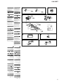
Model Name Using Similar Mechanism
XAV-65
Mechanism Type
DR28N-ABB-YG
SPECIFICATIONS
(US and Canadian models only)
FOR THE CUSTOMERS IN THE USA. NOT
APPLICABLE IN CANADA, INCLUDING IN THE
PROVINCE OF QUEBEC.
POUR LES CLIENTS AUX ÉTATS-UNIS. NON
APPLICABLE AU CANADA, Y COMPRIS LA
PROVINCE DE QUÉBEC.
AUDIO POWER SPECIFICATIONS
CEA2006 Standard
Power Output: 17 Watts RMS × 4 at
4 Ohms < 1% THD+N
SN Ratio: 80 dBA
(reference: 1 Watt into 4 Ohms)
Monitor section
Display type: Wide LCD color monitor
Dimensions: 6.2 in
System: TFT active matrix
Number of pixels:
1,152,000 pixels (800 × 3 (RGB) × 480)
Color system:
PAL/NTSC/SECAM/PAL-M automatic select
Tuner section (US, Canadian and E (NTSC) models)
FM
Tuning range: 87.5 – 107.9 MHz
FM tuning step: 100 kHz/200 kHz switchable
(E (NTSC) model only)
Antenna (aerial) terminal:
External antenna (aerial) connector
Intermediate frequency: 150 kHz
Usable sensitivity: 10 dBf
Selectivity: 70 dB at 400 kHz
Signal-to-noise ratio: 70 dB (mono)
Separation at 1 kHz: 30 dB
Frequency response: 20 - 15,000 Hz
AM
Tuning range: 530 – 1,710 kHz
Antenna (aerial) terminal:
External antenna (aerial) connector
Intermediate frequency:
9,267.5 kHz or 9,257.5 kHz/5 kHz
Sensitivity: 44 μV
Tuner section (AEP, Russian, UK, E (PAL),
Saudi Arabia, Indian and Australian models)
FM
Tuning range: 87.5 – 108.0 MHz
Antenna (aerial) terminal:
External antenna (aerial) connector
Intermediate frequency: 150 kHz
Usable sensitivity: 10 dBf
Selectivity: 70 dB at 400 kHz
Signal-to-noise ratio: 70 dB (mono)
Separation at 1 kHz: 30 dB
Frequency response: 20 - 15,000 Hz
AM
Tuning range: 531 – 1,602 kHz
Antenna (aerial) terminal:
External antenna (aerial) connector
Intermediate frequency:
9,267 kHz or 9,258 kHz/4.5 kHz
Sensitivity: 44 μV
DVD/CD Player section
Signal-to-noise ratio: 80 dB
Frequency response: 20 – 20,000 Hz
Wow and flutter: Below measurable limit
Harmonic distortion: 0.05%
Region code: Labeled on the bottom of the unit
USB Player section
Interface: USB (Full-speed)
Maximum current: 1 A
Wireless Communication
Communication System:
BLUETOOTH Standard version 3.0
Output:
BLUETOOTH Standard Power Class 2 (Max. +4
dBm)
Maximum communication range:
Line of sight approx. 10 m (33 ft)* 1
Frequency band:
2.4 GHz band (2.4000 – 2.4835 GHz)
Modulation method: FHSS
Compatible BLUETOOTH Profiles* 2:
A2DP (Advanced Audio Distribution Profile) 1.2
AVRCP (Audio Video Remote Control Profile) 1.4
HFP (Handsfree Profile) 1.6
PBAP (Phone Book Access Profile)
OPP (Object Push Profile)
SPP (Serial Port Profile)
*1 The actual range will vary depending on factors such
as obstacles between devices, magnetic fields
around a microwave oven, static electricity,
reception sensitivity, antenna’s performance,
operating system, software application, etc.
*2 BLUETOOTH standard profiles indicate the purpose
of BLUETOOTH communication between devices.
9-896-015-04
2015A33-1
© 2015.01
Sony Corporation
Published by Sony Techno Create Corporation
Power amplifier section
Outputs: Speaker outputs
Speaker impedance: 4 – 8 ohms
Maximum power output: 55 W × 4 (at 4 ohms)
General
Outputs:
Video output terminal (rear)
Audio output terminals (front, rear/sub
switchable)
Power antenna (aerial)/Power amplifier control
terminal (REM OUT)
Inputs:
Illumination control terminal
Remote controller input terminal
Antenna (aerial) input terminal
Microphone input terminal
Parking brake control terminal
Reverse input terminal
Camera input terminal
AUX audio input terminal (Front)
AUX Audio/Video input terminal (Rear)
USB port
External input terminal (E (PAL), Saudi Arabia,
Indian and Australian models only)
Power requirements: 12 V DC car battery
(negative ground (earth))
Dimensions: Approx. 178 mm × 101.5 mm × 169 mm
(7 1/ 8 × 4 × 6 3/ 4 in) (w/h/d)
Mounting dimensions:
(Except AEP, Russian and UK models)
Approx. 178 mm × 100 mm × 165 mm
(7 1/ 8 × 4 × 6 1/ 2 in) (w/h/d)
(AEP, Russian and UK models)
Approx. 182 mm × 100.6 mm × 159 mm
(7 1/ 4 × 4 3/ 8 × 6 3/ 8 in) (w/h/d)
Mass: Approx. 1.7 kg (3 lb 12 oz)
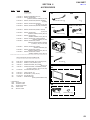
Package contents:
Parts for installation and connections (1 set)
Remote Commander (1): RM-X170
Microphone (1)
Design and specifications are subject to change
without notice.
Region code
The region system is used to protect software
copyrights.
The region code is located on the bottom of the
unit, and only DVDs labeled with an identical region
code can be played on this unit.
DVDs labeled
can also be played.
If you try to play any other DVD, the message
[Playback prohibited by region code.] will appear
on the monitor screen. Depending on the DVD, no
region code may be labeled even though playing
the DVD is prohibited by area restrictions.
AV CENTER
XAV-68BT
TABLE OF CONTENTS
Copyrights
US and foreign patents licensed from Dolby
Laboratories.
MPEG Layer-3 audio coding technology and patents
licensed from Fraunhofer IIS and Thomson.
Manufactured under license
from Dolby Laboratories. Dolby
and the double-D symbol are
trademarks of Dolby
Laboratories.
Windows Media is either a registered trademark or
trademark of Microsoft Corporation in the United
States and/or other countries.
This product is protected by certain intellectual
property rights of Microsoft Corporation. Use or
distribution of such technology outside of this
product is prohibited without a license from
Microsoft or an authorized Microsoft subsidiary.
“DVD VIDEO,” “DVD-R,” “DVD-RW,” “DVD+R,” and
“DVD+RW” are trademarks.
The Bluetooth® word mark and logos are registered
trademarks owned by Bluetooth SIG, Inc. and any
use of such marks by Sony Corporation is under
license. Other trademarks and trade names are
those of their respective owners.
iPhone, iPod, iPod classic, iPod nano, iPod touch,
and Siri are trademarks of Apple Inc., registered in
the U.S. and other countries.
THIS PRODUCT IS LICENSED UNDER THE MPEG-4
VISUAL PATENT PORTFOLIO LICENSE FOR THE
PERSONAL AND NON-COMMERCIAL USE OF A
CONSUMER FOR DECODING VIDEO IN COMPLIANCE
WITH THE MPEG-4 VISUAL STANDARD (“MPEG-4
VIDEO”) THAT WAS ENCODED BY A CONSUMER
ENGAGED IN A PERSONAL AND NONCOMMERCIAL
ACTIVITY AND/OR WAS OBTAINED FROM A VIDEO
PROVIDER LICENSED BY MPEG LA TO PROVIDE
MPEG-4 VIDEO.
NO LICENSE IS GRANTED OR SHALL BE IMPLIED FOR
ANY OTHER USE.
ADDITIONAL INFORMATION INCLUDING THAT
RELATING TO PROMOTIONAL, INTERNAL AND
COMMERCIAL USES AND LICENSING MAY BE
OBTAINED FROM MPEG LA, LLC. SEE
HTTP://WWW.MPEGLA.COM
Pandora, the Pandora logo, and the Pandora trade
dress are trademarks or registered trademarks of
Pandora Media, Inc., used with permission.
Google, Google Play and Android are trademarks of
Google Inc.
All other trademarks are trademarks of their
respective owners.
CAUTION
Use of controls or adjustments or performance of procedures
other than those specified herein may result in hazardous radiation exposure.
FLEXIBLE CIRCUIT BOARD REPAIRING
• Keep the temperature of soldering iron around 270 °C during
repairing.
• Do not touch the soldering iron on the same conductor of the
circuit board (within 3 times).
• Be careful not to apply force on the conductor when soldering
or unsoldering.
SAFETY-RELATED COMPONENT WARNING!
COMPONENTS IDENTIFIED BY MARK 0 OR DOTTED LINE
WITH MARK 0 ON THE SCHEMATIC DIAGRAMS AND IN
THE PARTS LIST ARE CRITICAL TO SAFE OPERATION.
REPLACE THESE COMPONENTS WITH SONY PARTS
WHOSE PART NUMBERS APPEAR AS SHOWN IN THIS
MANUAL OR IN SUPPLEMENTS PUBLISHED BY SONY.
ATTENTION AU COMPOSANT AYANT RAPPORT
À LA SÉCURITÉ!
LES COMPOSANTS IDENTIFIÉS PAR UNE MARQUE 0 SUR
LES DIAGRAMMES SCHÉMATIQUES ET LA LISTE DES
PIÈCES SONT CRITIQUES POUR LA SÉCURITÉ DE FONCTIONNEMENT. NE REMPLACER CES COMPOSANTS QUE
PAR DES PIÈCES SONY DONT LES NUMÉROS SONT DONNÉS DANS CE MANUEL OU DANS LES SUPPLÉMENTS
PUBLIÉS PAR SONY.
2
1.
SERVICING NOTES .............................................
3
2.
GENERAL ..................................................................
6
3.
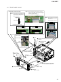
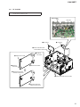
DISASSEMBLY
3-1.
3-2.
3-3.
3-4.
3-5.
3-6.
3-7.
3-8.
Disassembly Flow ...........................................................
Mini Fuse (Blade Type) (10 A) (F1), Cover ...................
Front Panel Block ...........................................................
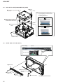
DVD Deck Assy (DR28N-ABB-YG) (DVM1) ..............
Guide Assy, BT ANT (ANT1) ........................................
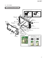
KEY Board......................................................................
BT MIC (Cable) (BTM1)................................................
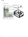
BT Board.........................................................................
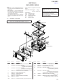
4.
ELECTRICAL ADJUSTMENT .......................... 20
5.
EXPLODED VIEWS
14
14
15
16
16
17
18
19
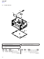
5-1. Overall Section ............................................................... 21
5-2. Chassis Section ............................................................... 22
6.
ACCESSORIES ....................................................... 23
XAV-68BT
Ver. 1.3
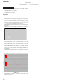
SECTION 1
SERVICING NOTES
NOTES ON HANDLING THE OPTICAL PICK-UP
BLOCK OR BASE UNIT
The laser diode in the optical pick-up block may suffer electrostatic break-down because of the potential difference generated by
the charged electrostatic load, etc. on clothing and the human body.
During repair, pay attention to electrostatic break-down and also
use the procedure in the printed matter which is included in the
repair parts.
The flexible board is easily damaged and should be handled with
care.
NOTES ON LASER DIODE EMISSION CHECK
The laser beam on this model is concentrated so as to be focused
on the disc reflective surface by the objective lens in the optical
pickup block. Therefore, when checking the laser diode emission,
observe from more than 30 cm away from the objective lens.
REPLACING THE LITHIUM BATTERY OF THE REMOTE
COMMANDER
Under normal conditions, the battery will last
approximately 1 year. (The service life may be
shorter, depending on the conditions of use.)
When the battery becomes weak, the range of the
remote commander becomes shorter. Replace the
battery with a new CR2025 lithium battery. Use of
any other battery may present a risk of fire or
explosion.
Notes on the lithium battery
Keep the lithium battery out of the reach of children.
Should the battery be swallowed, immediately
consult a doctor.
Wipe the battery with a dry cloth to assure a good
contact.
Be sure to observe the correct polarity when installing
the battery.
Do not hold the battery with metallic tweezers,
otherwise a short-circuit may occur.
WARNING
MODEL IDENTIFICATION
Battery may explode if mistreated.
Do not recharge, disassemble, or dispose of in
fire.
– Bottom View –
(US, Canadian, AEP, Russian, UK,
E (PAL) and Saudi Arabia models)
Region Code
(US and Canadian models)
Part No.
Region Code
(AEP and UK models)
Region Code
(Russian model)
Region Code
(E (PAL) and
Saudi Arabia models)
IMPORTANT NOTE FOR REPAIRING
XAV-68BT contain individual information that the customer registered because it installs the Bluetooth function.
When repairing, the data that the customer registered might disappear. Have the approval of the customer beforehand.
If any of the following repair is performed, that data disappears.
• Complete BT board replacing
• Initialize
Note: Replaced old complete BT board is destroyed with the hammer,
and throw out it.
ABOUT THE SECURITY FUNCTION
This unit does not use security function by password lock.
– Bottom View –
(E (NTSC), Indian and Australian models)
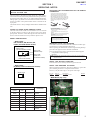
ABOUT THE REPAIRING OF BOARD
When each boards installed on this unit are defective, replace the
parts including the board or complete mounted board.
However, only the following IC can replace with single.
Region Code
Ref. No.
U308
Part No.
Description
9-885-201-53 IC LM1117-ADJ
Remark
– MAIN Board (Top view) –
Part No.
Label indication
Destination
Signal format
system
Region
code
Part No.
NTSC
1
4-540-917-0[]
US and Canadian
models
NTSC
4
4-540-918-0[]
E (NTSC) model
PAL
3
4-540-919-0[]
E (PAL) model
PAL
5
4-540-921-0[]
Indian model
PAL
5
4-540-922-0[]
Russian model
PAL
2
4-558-481-0[]
Saudi Arabia model
PAL
4
4-558-482-0[]
Australian model
PAL
2
4-564-299-0[]
AEP and UK
models
U308
3
XAV-68BT
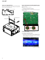
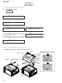
NOTE FOR TRANSPORTATION
When this unit is transported, it is necessary to install two transportation screws. Please transport it after installing two transportation
screws as shown in the figure below.
NOTE OF REPLACING THE CHASSIS MAIN ASSY (CHA1)
When the chassis MAIN assy (CHA1) is replaced, the destination
setting is necessary.
Part No.
Description
A-2018-257-A SCREW WITH WARNING LABEL
1. Preparing the Destination Setting
Be sure to solder the SL001 on the MAIN board before doing the
destination setting.
G
IN
N
R
A
W
– MAIN Board (Component Side) –
!!!
Transportation screw
u2
Note: Remote commander is necessary.
Warning label
u1
transportation screw
transportation screw
warning label
WA
R
NI
NG
!!!
SL001
SL001
2. Destination Setting
Set destination according to the procedure below.
2-1. Setting the Destination Code
1. In the state of source off (Home screen is displayed), enter
the destination setting mode by pressing the buttons on the
remote commander in order of the [4] t [5] t [6] (press
only the [6] button for two seconds).
– Continued on next page –
4
XAV-68BT
Ver. 1.3
2. The following screen is displayed and the destination setting
mode becomes effective.
(Displayed characters/values in the following figure are example)
Note: Refer to following “2-2. Entering the Destination Code” for operation method.
Destination setting checking method:
1. In the state of source off (Home screen is displayed), enter the
test mode by pressing the buttons on the remote commander in
order of the [4] t [5] t [0] (press only the [0] button for two
seconds).
<DESTINATION SETTING MODE>
0 0 0 0 0 1
EUR: 000000
UC: 000001
E17: 000012
E: 000003
RU2: 000004
IN: 000015
EA: 00001A
ET4: 00001C
3. The resetting operation is executed by pressing the [ENTER]
button on the remote commander the setting ends, and the unit
returns to the normal condition.
2-2. Entering the Destination Code
Note 1: Input of the destination code cannot be performed by the keys of
main unit. Be sure to input the destination code by remote commander.
•
Method of operation by remote commander
Note 2: The ten key cannot be used.
2. The following screen is displayed and confirm that item of the
destination has been rewritten correctly.
(Displayed characters/values in the following figure are example)
<Test Mode>
1.AUDIO FACTORY MODE
2.AUDIO DEBUG MODE
4.VISUAL FACTORY MODE
6.DESTINATION SETTING MODE
DEST: UC REGION: 1 PAN ID: AA2C43FD
MCU: SONY-ST02-140515
Graphic: SONY-TW02-140514
Mecha: SONY-SP02-140514
Servo: HI6CD1-BBA-893D
BT: H10077-V2R78-20001 / SONY:XAV-68BT
3. The resetting operation is executed by pressing the [ENTER]
button on the remote commander the confirming ends, and the
unit returns to the normal condition.
4. Processing After the Destination Setting
Be sure to unsolder the SL001 on the MAIN board after doing the
destination setting.
1. Press the [V] or [v] button, and select the alphanumeric character of “0 to F”.
2. The digit advances by pressing the [b] button.
The digit returns by pressing the [B] button.
3. The setting is completed by pressing the [ENTER] button, and
the initialization operation is done.
– MAIN Board (Component Side) –
2-3. Destination Code
Destination
AEP and UK models
US and Canadian models
E (NTSC) model
E (PAL) model
Saudi Arabia model
Indian model
Australian model
Russian model
Destination code
000000
000001
000003
000012
00001A
000015
00001C
000004
3. Confirmation After Destination Setting
Execute the following operation after completing the destination
setting, and confirm a correct destination was set.
SL001
SL001
5
XAV-68BT
SECTION 2
GENERAL
This section is extracted
from instruction manual.
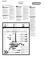
(US and Canadian models)
ɠTo a car’s illumination signal
Cautions
ɡTo the +12 V power terminal which is
energized when the ignition switch is set to
the accessory position
Be sure to first connect the black ground (earth) lead to a
common ground (earth) point.
ˎRun all ground (earth) leads to a common ground
(earth) point.
ˎThis unit is designed for negative ground (earth) 12 V
DC operation only.
ˎDo not disassemble or modify the unit.
ˎDo not install in locations which interfere with airbag
operation.
ˎDo not get the leads under a screw, or caught in
moving parts (e.g. seat railing).
ˎBefore making connections, turn the car ignition off
to avoid short circuits.
ˎConnect the yellow and red power supply leads
only after all other leads have been connected.
ˎBe sure to insulate any loose unconnected leads
with electrical tape for safety.
ˎThe use of optical instruments with this product will
increase eye hazard.
ˎDo not press on the LCD when installing the unit.
Notes on the power supply lead (yellow)
ˎWhen connecting this unit in combination with other
stereo components, the amperage rating of the car
circuit to which the unit is connected must be higher
than the sum of each component's fuse amperage
rating.
ˎIf no car circuits are rated high enough, connect the
unit directly to the battery.
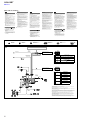
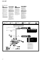
Connection diagram
ɞTo a common ground (earth) point
ɟTo the power antenna (aerial) control lead or
the power supply lead of the antenna (aerial)
booster
Précautions
Notes
ˎIf there is no accessory position, connect to the +12 V power
(battery) terminal which is energized at all times.
Be sure to first connect the black ground (earth) lead to a
common ground (earth) point.
ˎIf your car has a built-in FM/AM antenna (aerial) in the rear/
side glass, see “Notes on the control and power supply leads.”
ɢTo the +12 V power terminal which is
energized at all times
Be sure to first connect the black ground (earth) lead to a
common ground (earth) point.
ɣTo the parking brake switch cord
The mounting position of the parking brake switch cord depends
on your car. For details, see “Connecting the parking brake lead
(Ƕ)” on the reverse side.
ʭTo an auxiliary device such as a portable
media player, game console, etc. (not
supplied)
Tip
You can use an RCA pin cord (not supplied) to connect auxiliary
devices.
ʮTo the +12 V power terminal of the car’s rear
lamp lead (only when connecting the rear
view camera)
Notes on the control and power supply leads
ˎREM OUT lead (blue/white striped) supplies +12 V DC when you turn
on the unit.
ˎIf your car has built-in FM/AM antenna (aerial) in the rear/side
glass, connect REM OUT lead (blue/white striped) or the accessory
power supply lead (red) to the power terminal of the existing
antenna (aerial) booster. For details, consult your dealer.
ˎA power antenna (aerial) without a relay box cannot be used with
this unit.
Memory hold connection
When the yellow power supply lead is connected, power will always
be supplied to the memory circuit even when the ignition switch is
turned off.
First connect the black ground (earth) lead, then connect the
yellow and red power supply leads.
Notes on speaker connection
ˎBefore connecting the speakers, turn the unit off.
ˎUse speakers with an impedance of 4 to 8 ohms, and with
adequate power handling capacities to avoid damage.
ˎDo not connect the speaker terminals to the car chassis, or connect
the terminals of the right speakers with those of the left speakers.
ˎDo not connect the ground (earth) lead of this unit to the negative
(–) terminal of a speaker.
ˎDo not attempt to connect the speakers in parallel.
ˎConnect only passive speakers. Connecting active speakers (with
built-in amplifiers) to the speaker terminals may damage the unit.
ˎTo avoid a malfunction, do not use the built-in speaker leads
installed in your car if they feature a common negative (–) lead for
the right and left speakers.
ˎDo not connect the unit’s speaker leads to each other.
Notes
ˎIt is not necessary to connect this lead if there is no power
antenna (aerial) or antenna (aerial) booster, or with a
manually-operated telescopic antenna (aerial).
ˎIf your car has a built-in FM/AM antenna (aerial) in the rear/
side glass, see “Notes on the control and power supply leads.”
To AMP REMOTE IN of an optional power
amplifier
This connection is only for amplifiers. Connecting any other
system may damage the unit.
ɡÀ la borne +12 V qui est alimentée lorsque la
clé de contact est sur la position accessoires
Français
English
Note on connection
To use the monitor for the rear seats, connect the parking brake
switch cord to the ground (earth).
ˎRassemblez tous les câbles de mise à la masse en
un point de masse commun.
ˎCet appareil est exclusivement conçu pour
fonctionner sur une tension de 12 V CC avec masse
négative.
ˎNe démontez pas ou ne modifiez pas l’appareil.
ˎN’installez pas cet appareil dans des endroits
susceptibles de gêner le fonctionnement des
coussins de sécurité gonflables.
ˎÉvitez de fixer des vis sur les câbles ou de coincer
ceux-ci dans des pièces mobiles (par exemple,
armature de siège).
ˎAvant d’effectuer les raccordements, coupez le
moteur pour éviter un court-circuit.
ˎRaccordez les câbles d’alimentation jaune et rouge
seulement après avoir terminé tous les autres
raccordements.
ˎPour des raisons de sécurité, veillez à isoler avec du
ruban isolant tout câble libre non raccordé.
ˎL’utilisation d’instruments optiques avec ce produit
augmente les risques pour les yeux.
ˎN’exercez pas de pression sur l’écran ACL lors de
l’installation de l’appareil.
Remarques sur le câble d’alimentation (jaune)
ˎLorsque cet appareil est raccordé à d’autres
éléments stéréo, l’intensité nominale du circuit de
voiture auquel l’appareil est raccordé doit être
supérieure à la somme de l’intensité nominale des
fusibles de chaque élément.
ˎSi aucun circuit de la voiture n’est assez puissant,
raccordez directement l’appareil à la batterie.
Schéma de raccordement
ɞÀ un point de masse commun
Branchez d’abord le câble de mise à la masse noir et, ensuite, les
câbles d’alimentation jaune et rouge.
ɟVers le câble de commande d’antenne
électrique ou le câble d’alimentation de
l’amplificateur d’antenne
Remarques
ˎIl n’est pas nécessaire de raccorder ce câble s’il n’y a pas
d’antenne électrique ni d’amplificateur d’antenne, ou avec une
antenne télescopique manuelle.
ˎSi votre voiture est équipée d’une antenne FM/AM intégrée
dans la vitre arrière/latérale, voir « Remarques sur les câbles de
commande et d’alimentation ».
Au niveau de AMP REMOTE IN de
l’amplificateur de puissance en option
Ce raccordement s’applique uniquement aux amplificateurs. Le
branchement de tout autre système risque d’endommager
l’appareil.
Remarques
ˎS’il n’y a pas de position accessoires, raccordez à la borne
d’alimentation (batterie) +12 V qui est alimentée en
permanence.
Raccordez d’abord le câble de mise à la masse noir à un point
de masse commun.
ˎSi votre voiture est équipée d’une antenne FM/AM intégrée
dans la vitre arrière/latérale, voir « Remarques sur les câbles de
commande et d’alimentation ».
ɢÀ la borne +12 V qui est alimentée en
permanence
Raccordez d’abord le câble de mise à la masse noir à un point de
masse commun.
ɣ Vers le cordon du capteur du frein à main
La position de montage du cordon du capteur du frein à main
dépend de votre véhicule. Pour plus de détails, consultez
« Raccordement du cordon du frein à main (Ƕ) » au verso.
ʭVers un appareil auxiliaire, tel qu’un lecteur
multimédia portatif, une console de jeu, etc.
(non fourni(e))
Conseil
Vous pouvez utiliser un câble RCA (non fourni) pour raccorder les
appareils auxiliaires.
ʮÀ la borne +12 V du câble des feux arrière du
véhicule (uniquement en cas de
raccordement de la caméra avec vue arrière)
Remarques sur les câbles de commande et d’alimentation
ˎLe câble REM OUT (rayé bleu/blanc) fournit une alimentation de
+12 V CC lorsque vous mettez l’appareil en marche.
ˎLorsque votre voiture est équipée d’une antenne FM/AM intégrée
dans la vitre arrière/latérale, raccordez le câble REM OUT (rayé
bleu/blanc) ou le câble d’alimentation des accessoires (rouge) à la
borne d’alimentation de l’amplificateur d’antenne existant. Pour
plus de détails, consultez votre détaillant.
ˎUne antenne électrique sans boîtier de relais ne peut pas être
utilisée avec cet appareil.
Raccordement pour la conservation de la mémoire
Lorsque le câble d’alimentation jaune est raccordé, le circuit de la
mémoire est alimenté en permanence même si la clé de contact est
sur la position d’arrêt.
Remarques sur le raccordement des haut-parleurs
ˎAvant de raccorder les haut-parleurs, mettez l’appareil hors tension.
ˎUtilisez des haut-parleurs ayant une impédance de 4 à 8 ohms avec
une capacité électrique adéquate pour éviter de causer des
dommages.
ˎNe raccordez pas les bornes du système de haut-parleur au châssis
de la voiture et ne raccordez pas les bornes des haut-parleurs droits
à celles des haut-parleurs gauches.
ˎNe raccordez pas le câble de mise à la masse de cet appareil à la
borne négative (–) d’un haut-parleur.
ˎN’essayez pas de raccorder les haut-parleurs en parallèle.
ˎRaccordez uniquement des haut-parleurs passifs. Le raccordement
de haut-parleurs actifs (avec amplificateurs intégrés) aux bornes
des haut-parleurs peut endommager l’appareil.
ˎPour éviter tout problème de fonctionnement, n’utilisez pas les
câbles de haut-parleurs intégrés installés dans votre voiture s’ils
possèdent un câble négatif commun (–) pour les haut-parleurs droit
et gauche.
ˎNe raccordez pas entre eux les câbles des haut-parleurs de
l’appareil.
Remarque sur le raccordement
Si vous avez l’intention d’utiliser le moniteur pour les sièges arrière,
raccordez le cordon du capteur du frein à main à la masse.
ɠVers le signal d’éclairage de la voiture
Español
Precauciones
ˎConecte todos los cables de conexión a masa a un
punto común.
ˎEsta unidad ha sido diseñada para alimentarse
solamente con cc de 12 V de masa negativa.
ˎNo desmonte ni modifique la unidad.
ˎNo instale la unidad en lugares en los que interfiera
con el funcionamiento del airbag.
ˎNo coloque los cables debajo de ningún tornillo, ni
los aprisione con partes móviles (p. ej. los raíles del
asiento).
ˎAntes de realizar las conexiones, desactive el
encendido del automóvil para evitar cortocircuitos.
ˎConecte los cables de fuente de alimentación
amarillo y rojo solamente después de haber
conectado los demás.
ˎPor razones de seguridad, asegúrese de aislar con
cinta aislante los cables sueltos que no estén
conectados.
ˎEl uso de instrumentos ópticos con este producto
aumenta el riesgo de sufrir daños oculares.
ˎNo presione la pantalla LCD cuando instale la
unidad.
Notas sobre el cable de fuente de alimentación
(amarillo)
ˎCuando conecte esta unidad en combinación con
otros componentes estéreo, la capacidad nominal
del circuito conectado del automóvil debe ser
superior a la suma del fusible de cada componente.
ˎSi no hay circuitos del automóvil con capacidad
nominal suficientemente alta, conecte la unidad
directamente a la batería.
Diagrama de conexiones
ɞA un punto de conexión a masa común
Conecte primero el cable negro de conexión a masa, y después
los cables rojo y amarillo de fuente de alimentación.
ɟAl cable de control de la antena motorizada o
al cable de fuente de alimentación del
amplificador de señal de la antena
Notas
ˎSi no se dispone de antena motorizada ni de amplificador de
señal de la antena, o se utiliza una antena telescópica
accionada manualmente, no será necesario conectar este
cable.
ˎSi el automóvil tiene una antena FM/AM integrada en el cristal
posterior o lateral, consulte las “Notas sobre los cables de
control y de fuente de alimentación”.
A AMP REMOTE IN de un amplificador de
potencia opcional
Esta conexión es sólo para amplificadores. La conexión de
cualquier otro sistema puede dañar la unidad.
ɠA una señal de iluminación del automóvil
Raccordez d’abord le câble de mise à la masse noir à un point de
masse commun.
Asegúrese de conectar primero el cable negro de conexión a
masa a un punto de conexión a masa común.
ɡAl terminal de alimentación de +12 V que
recibe energía en la posición de accesorio del
interruptor de la llave de encendido
Notas
ˎSi no hay posición de accesorio, conéctelo al terminal de
alimentación (batería) de +12 V que recibe energía sin
interrupción.
Asegúrese de conectar primero el cable negro de conexión a
masa a un punto de conexión a masa común.
ˎSi el automóvil tiene una antena FM/AM integrada en el cristal
posterior o lateral, consulte las “Notas sobre los cables de
control y de fuente de alimentación”.
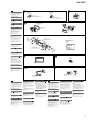
Equipment used in illustrations (not supplied) / Appareils utilisés dans les illustrations (non fournis) / Equipo utilizado en las ilustraciones (no suministrado)
Front speaker
Haut-parleur avant
Altavoz frontal
Rear speaker
Haut-parleur arrière
Altavoz posterior
Rear view camera
Caméra avec vue arrière
Cámara retrovisora
Power amplifier
Amplificateur de puissance
Amplificador de potencia
Subwoofer
Caisson de graves
Altavoz potenciador de graves
Monitor
Moniteur
Monitor
ɢAl terminal de alimentación de +12 V que
recibe energía sin interrupción
Asegúrese de conectar primero el cable negro de conexión a
masa a un punto de conexión a masa común.
ɣ Al cable de conmutación del freno de
estacionamiento
La posición de montaje del cable de conmutación del freno de
estacionamiento depende del automóvil. Para obtener detalles,
vea la sección “Conexión del cable del freno de estacionamiento
(Ƕ)” del lado reverso.
ʭA un dispositivo auxiliar, como, por ejemplo,
un reproductor portátil, una consola de
videojuegos, etc. (no suministrados)
ˬ
Sugerencia
Es posible utilizar el cable con terminales RCA (no suministrado)
para conectar dispositivos auxiliares.
Black
Noir
Negro
GND
Red
Rouge
Rojo
Blue/white striped
Rayé bleu/blanc
Con rayas azules/blancas
REM OUT
Max. supply current: 0.4 A
Courant max. fourni : 0,4 A
Corriente máx. de alimentación: 0,4 A
ILLUMINATION
ACC
Yellow
Jaune
Amarillo
Orange/white striped
Rayé orange/blanc
Con rayas naranjas/blancas
ʮAl terminal de alimentación de +12 V del
cable del indicador posterior del automóvil
(únicamente cuando conecte la cámara
retrovisora)
Notas sobre los cables de control y de fuente de alimentación
ˎEl cable REM OUT (rayado azul y blanco) suministra cc +12 V al
encender la unidad.
ˎSi el automóvil dispone de una antena de FM/AM incorporada en el
cristal trasero o lateral, conecte el cable REM OUT (rayado azul y
blanco) o el cable de fuente de alimentación auxiliar (rojo) al
terminal de alimentación del amplificador de señal de la antena
existente. Para obtener más detalles, consulte a su distribuidor.
ˎCon esta unidad no es posible utilizar una antena motorizada sin
caja de relé.
BATTERY
Light green
Vert clair
Verde claro
Conexión para protección de la memoria
Si conecta el cable amarillo de fuente de alimentación, el circuito de
la memoria recibirá siempre alimentación, aunque apague el
interruptor de encendido.
PARKING BRAKE
White
Blanc
Blanco
Purple/white striped
Rayé mauve/blanc
Violeta/con rayas blancas
White/black striped
Rayé blanc/noir
Con rayas blancas/negras
Gray
Gris
Gris
Gray/black striped
Rayé gris/noir
Con rayas grises/negras
Green
Vert
Verde
Left
Gauche
Izquierdo
Notas sobre la conexión de los altavoces
ˎAntes de conectar los altavoces, desconecte la alimentación de la
unidad.
ˎUtilice altavoces con una impedancia de 4 a 8 Ω con la capacidad
de potencia adecuada para evitar que se dañen.
ˎNo conecte los terminales de altavoz al chasis del automóvil ni
conecte los terminales de altavoz derecho con los del izquierdo.
ˎNo conecte el cable de conexión a masa de esta unidad al terminal
negativo (–) del altavoz.
ˎNo intente conectar los altavoces en paralelo.
ˎConecte solamente altavoces pasivos. Si conecta altavoces activos
(con amplificadores incorporados) a los terminales de altavoz,
puede dañar la unidad.
ˎPara evitar fallas de funcionamiento, no utilice los cables de altavoz
integrados instalados en el automóvil si la unidad comparte un
cable negativo común (–) para los altavoces derecho e izquierdo.
ˎNo conecte los cables de altavoz de la unidad entre sí.
Right
Droit
Derecho
Nota sobre la conexión
Si va a utilizar el monitor para los asientos posteriores, conecte el
cable de conmutación del freno de estacionamiento a masa.
Left
Gauche
Izquierdo
Green/black striped
Rayé vert/noir
Con rayas verdes/negras
*1
Purple
Mauve
Morado
Right
Droit
Derecho
Purple/black striped
Rayé mauve/noir
Con rayas moradas/negras
ʓ
Fuse (10 A)
Fusible (10 A)
Fusible (10 A)
ʖ*4
*1 RCA pin cord (not supplied)
*2 The supplied cable for Steering Control is connected or a separate adaptor may
be required. For details on the connectivity of your vehicle, visit the support site
on the back page of Operation Instructions.
*3 AUDIO OUT can be switched SUB or REAR. For details, see the supplied Operating
Instructions.
4
* For details on installing the microphone, see “Installing the microphone (˲)” on
the reverse side.
*5 Whether in use or not, route the microphone input cord such that it does not
interfere with driving. Secure the cord with a clamp, etc., if it is installed around
your feet.
From car antenna
(aerial)
À partir de
l’antenne de la
voiture
Desde la antena del
automóvil
*1
*1
*1 Cordon à broches RCA (non fourni)
*2 Le câble fourni pour la fonction Steering Control (commande du volant) est
raccordé ou un adaptateur distinct pourrait être requis. Pour plus de détails sur la
connectivité de votre véhicule, visitez le site d’assistance à l’adresse indiquée sur
la page arrière du Mode d’emploi.
*3 AUDIO OUT peut être commutée entre SUB et REAR. Pour plus de détails,
consultez le mode d’emploi fourni.
4
* Pour les détails sur l’installation du microphone, référez-vous à « Installation du
microphone (˲) » au verso.
*5 Qu’il soit en usage ou non, acheminez le cordon d’entrée du microphone de telle
sorte qu’il ne gêne pas votre conduite. Fixez le cordon à l’aide d’une attache, etc.,
s’il est installé autour de vos pieds.
*1 Cable con terminales RCA (no suministrado)
*2 El cable suministrado para Ctrl. en el volante se encuentra conectado o puede
necesitar un adaptador por separado. Para obtener más detalles sobre la
conectividad de su vehículo, visite el sitio de soporte que se encuentra en la
última página del Manual de instrucciones.
*3 AUDIO OUT puede cambiarse a SUB o REAR. Para obtener más detalles, consulte
el Manual de instrucciones.
*4 Para obtener detalles sobre la instalación del micrófono, consulte “Instalación del
micrófono (˲)” al reverso.
*5 Se esté utilizando o no, coloque el cable de entrada del micrófono de modo que
no interfiera en el manejo del automóvil. Si instala los cables cerca de la zona de
los pies, fíjelos con una abrazadera, etc.
6
XAV-68BT
English
Precautions
ˎChoose the installation location carefully so that the
unit will not interfere with normal driving operations.
ˎAvoid installing the unit in areas subject to dust, dirt,
excessive vibration, or high temperature, such as in
direct sunlight or near heater ducts.
ˎUse only the supplied mounting hardware for a safe
and secure installation.
˭
ˮ
Hand brake type
Type de frein à main
Tipo de freno manual
Foot brake type
Type de frein à pied
Tipo de freno de pedal
Parking brake switch cord
Cordon du capteur du frein à main
Cable de conmutación del freno de estacionamiento
Mounting angle adjustment
Parking brake switch cord
Cordon du capteur du frein à main
Cable de conmutación del freno de estacionamiento
Adjust the mounting angle to less than 45°.
Connecting the parking brake
lead
Be sure to connect the parking brake lead (light green)
of the power supply connection cable ʓ to the
parking brake switch cord.
Removing the pre-installed
screws
˯A
Larger than 182 mm (7 1/4 in)
Supérieure à 182 mm (7 1/4 po)
Superior a 182 mm
Before installing the unit, remove the pre-installed
screws from the unit.
Mounting the unit
Larger than 111 mm (4 3/8 in)
Supérieure à 111 mm (4 3/8 po)
Superior a 111 mm
Ǹ-A Mounting the unit with an
installation kit (not supplied)
1
Before installing, make sure that the catches on
both sides of the bracket are bent inwards
3.5 mm (5/32 in).
2
3
4
Position the bracket inside the dashboard.
Bracket
Support
Soporte
Bend the claws outward for a tight fit.
Mount the unit onto the bracket.
Dashboard
Tableau de bord
Tablero
q
Claws
Griffes
Uñas
Catch
Loquet
Enganche
Note
If the catches are straight or bent outwards, the unit will not be
installed securely and may spring out.
Ǹ-B Mounting the unit in a Japanese car
You may be able to install this unit in some makes of
Japanese cars without the bracket. If you cannot,
consult your Sony dealer.
B
Size:
ʕ
5 × max. 8 mm
(7/32 × max. 5/ 16 in)
Dimension :
5 × max. 8 mm
(7/32 × 5/ 16 po max.)
Tamaño:
5 × 8 mm máx.
When mounting this unit to the preinstalled brackets
of your car, use the supplied screws ʕ in the
appropriate screw holes, based on your car: T for
TOYOTA, M for MITSUBISHI and N for NISSAN.
Notes
ˎTo avoid a malfunction, install only with the supplied screws ʕ.
ˎDo not apply excessive force to the buttons of the unit.
ˎDo not press on the LCD.
ˎBefore mounting, make sure there is nothing on the top of the unit.
To the dashboard/center console
Vers le tableau de bord/la console centrale
Al tablero o consola central
Warning if your car’s ignition has
no ACC position
Bracket
Support
Soporte
After turning the ignition off, be sure to press and hold
OFF on the unit until the display disappears.
Otherwise, the display does not turn off and this
causes battery drain.
Parts supplied with your car
Pièces existantes fournies avec la voiture
Partes suministradas con el automóvil
Reset button
When the installation and connections are completed,
be sure to press the reset button with a ballpoint pen,
etc.
Installing the microphone
ʕ
Size:
5 × max. 8 mm
(7/32 × max. 5/16 in)
Dimension :
5 × max. 8 mm
(7/32 × 5/ 16 po max.)
Tamaño:
5 × 8 mm máx.
Bracket
Support
Soporte
Fuse replacement
When replacing the fuse, be sure to use one matching
the amperage rating stated on the original fuse. If the
fuse blows, check the power connection and replace
the fuse. If the fuse blows again after replacement,
there may be an internal malfunction. In such a case,
consult your nearest Sony dealer.
Location of screw holes
Emplacement des trous de vis
Ubicación de los orificios para los tornillos
T: TOYOTA
M: MITSUBISHI
N: NISSAN
˰
˱
To capture your voice during handsfree calling, you
need to install the microphone ͩ.
Fuse (10 A)
Fusible (10 A)
Fusible (10 A)
Cautions
ˎKeep the microphone away from extremely high
temperatures and humidity.
ˎIt is extremely dangerous if the cord becomes
wound around the steering column or gearstick. Be
sure to keep it and other parts from obstructing your
driving.
ˎIf airbags or any other shock-absorbing equipment
is in your car, contact the store where you purchased
this unit, or the car dealer, before installation.
˲-A Installing on the sun visor
Install clips (not supplied) and adjust the length and
position of the cord so that it does not obstruct your
driving.
˲-B Installing on the dashboard
Install a clip (not supplied) and adjust the length and
position of the cord so that it does not obstruct your
driving.
˲A
B
Notes
ˎBefore attaching the double-sided tape , clean the surface of the
dashboard with a dry cloth.
ˎAdjust the microphone angle to the proper position.
Clip (not supplied)
Clip (non fourni)
Clip (no suministrado)
Clips (not supplied)
Clips (non fournis)
Clips (no suministrados)
Français
Précautions
ˎChoisissez soigneusement l’emplacement
d’installation pour que l’appareil ne gêne pas le
conducteur pendant la conduite.
ˎÉvitez d’installer l’appareil dans un endroit exposé à
la poussière, à la saleté, à des vibrations excessives
ou à des températures élevées comme en plein
soleil ou à proximité de conduits de chauffage.
ˎPour garantir un montage sûr, n’utilisez que le
matériel fourni.
Réglage de l’angle de montage
Ajustez l’inclinaison à un angle inférieur à 45°.
Raccordement du cordon du frein
à main
Veillez à raccorder le cordon du frein à main (vert clair)
du câble de raccordement d’alimentation ʓ au
cordon du capteur du frein à main.
Retrait des vis préinstallées
Avant d’installer l’appareil, retirez les vis
préinstallées de l’appareil.
Montage de l’appareil
Ǹ-A Montage de l’appareil avec un
ensemble d’installation (non fourni)
1
Avant l’installation, assurez-vous que les loquets
des deux côtés du support sont bien pliés de
3,5 mm (5/32 po) vers l’intérieur.
2
3
Placez le support dans le tableau de bord.
4
Installez l’appareil sur le support.
Pliez les griffes vers l’extérieur pour obtenir une
prise solide.
Remarque
Si les loquets sont droits ou pliés vers l’extérieur, l’appareil ne peut
pas être fixé solidement et peut se détacher.
Ǹ-B Montage de l’appareil dans une
voiture japonaise
Il peut être possible d’installer cet appareil dans
certaines voitures de marques japonaises sans le
support. Dans le cas contraire, consultez votre
détaillant Sony le plus proche.
Si vous installez cet appareil sur les supports
préinstallés de votre véhicule, faites passer les vis ʕ
fournies par les trous de vis appropriés, en fonction de
votre véhicule : T pour TOYOTA, M pour MITSUBISHI et
N pour NISSAN.
Remarques
ˎPour éviter tout problème de fonctionnement, utilisez uniquement
les vis ʕ fournies pour le montage.
ˎN’exercez pas de pression excessive sur les touches de l’appareil.
ˎN’exercez aucune pression sur l’écran ACL.
ˎAvant de procéder au montage, assurez-vous que rien ne se trouve
au-dessus de l’appareil.
Avertissement si le contact de
votre véhicule ne comporte pas
de position ACC
Après avoir coupé le contact, assurez-vous de
maintenir enfoncée la touche OFF de l’appareil jusqu’à
ce que l’affichage disparaisse.
Sinon, l’affichage ne s’éteint pas, ce qui risque
d’épuiser la batterie.
Touche de réinitialisation
Installation du microphone
Español
Pour capturer votre voix durant les appels mains
libres, vous devez installer le microphone ͩ.
Mises en garde
ˎN’exposez pas le microphone à des températures
extrêmement élevées et à l’humidité.
ˎVeillez à ce que le cordon ne soit pas enroulé autour
du volant ou du levier de vitesses. Ceci peut s’avérer
extrêmement dangereux. Veillez à ce que le cordon
et les autres pièces ne gênent pas votre conduite.
ˎSi un système de coussins de sécurité gonflables ou
tout autre équipement absorbant les chocs est
présent dans votre véhicule, contactez le magasin
où vous avez acheté cet appareil ou votre
concessionnaire avant l’installation.
Precauciones
ˎElija cuidadosamente el lugar de montaje de forma
que la unidad no interfiera con las funciones
normales de conducción.
ˎEvite instalar la unidad donde pueda quedar
sometida a polvo, suciedad, vibraciones excesivas o
altas temperaturas como, por ejemplo, a la luz solar
directa o cerca de conductos de calefacción.
ˎPara realizar una instalación segura y firme, utilice
solamente elementos de instalación suministrados.
Ajuste del ángulo de montaje
Ajuste el ángulo de montaje a menos de 45°.
˲-A Fixation sur le pare-soleil
Installez les clips (non fournis) et ajustez la longueur
et la position du cordon de façon à ce qu’il ne gêne
pas la conduite.
˲-B Fixation sur le tableau de bord
Installez un clip (non fourni) et ajustez la longueur et
la position du cordon de façon à ce qu’il ne gêne pas
la conduite.
Remarques
ˎAvant de fixer l’adhésif double face , nettoyez la surface du
tableau de bord avec un chiffon sec.
ˎRéglez l’angle du microphone afin de le positionner correctement.
Conexión del cable del freno de
estacionamiento
Asegúrese de conectar el cable del freno de
estacionamiento (verde claro) del cable de conexión
de la fuente de alimentación ʓ al cable de
conmutación del freno de estacionamiento.
Extracción de los tornillos
preinstalados
Antes de instalar la unidad, extraiga los tornillos
preinstalados de ésta.
Une fois que l’installation et les raccordements sont
terminés, veillez à appuyer sur la touche de
réinitialisation à l’aide d’un stylo à bille, etc.
Remplacement du fusible
Lorsque vous remplacez le fusible, veillez à utiliser un
fusible dont l’intensité, en ampères, correspond à la
valeur indiquée sur le fusible usagé. Si le fusible grille,
vérifiez le branchement de l’alimentation et remplacez
le fusible. Si le nouveau fusible grille également, il est
possible que l’appareil soit défectueux. Dans ce cas,
consultez votre détaillant Sony le plus proche.
Montaje de la unidad
Ǹ-A Montaje de la unidad con un kit de
instalación (no suministrado)
1
Antes de instalar la unidad, compruebe que los
enganches de ambos lados del soporte estén
doblados hacia adentro 3,5 mm.
2
3
Coloque el soporte dentro del salpicadero.
4
Monte la unidad dentro del soporte.
Doble los ganchos hacia fuera para conseguir
una fijación segura.
Ǹ-B Montaje de la unidad en un
automóvil japonés
Es posible que pueda instalar la unidad en algunos
automóviles japoneses sin el soporte. En caso de que
no pudiera, consulte al distribuidor Sony más cercano.
Cuando monte la unidad en los soportes
preinstalados de su automóvil, utilice los tornillos
suministrados ʕ en los orificios para tornillos
correspondientes en función de su automóvil: T para
TOYOTA, M para MITSUBISHI y N para NISSAN.
Notas
ˎPara evitar que se produzcan fallas de funcionamiento, realice la
instalación solamente con los tornillos suministrados ʕ.
ˎNo ejerza fuerza excesiva sobre los botones de la unidad.
ˎNo presione la pantalla LCD.
ˎAsegúrese de que no hay ningún objeto encima de la unidad antes
de montarla.
Advertencia: si el encendido del
automóvil no dispone de una
posición ACC
Luego de apagarla, asegúrese de mantener
presionado OFF en la unidad hasta que la pantalla
desaparezca.
De lo contrario, la pantalla no se apaga y esto produce
que se agote la batería.
Botón de reinicio
Instalación del micrófono
Para capturar la voz durante llamadas con manos
libres, debe instalar el micrófono ͩ.
Precauciones
ˎMantenga el micrófono alejado de lugares con
humedad y temperaturas muy altas.
ˎQue el cable se enrolle alrededor del volante o de la
palanca de cambios es extremadamente peligroso.
Asegúrese de impedir que el cable y otros
componentes obstruyan la conducción.
ˎSi el vehículo dispone de airbags u otros dispositivos
de amortiguación de impactos, póngase en contacto
con el establecimiento donde ha adquirido esta
unidad o con el concesionario de automóviles antes
de llevar a cabo la instalación.
˲-A Instalación en la visera
Instale los clips (no suministrados) y ajuste la longitud
y la posición del cable de modo que no obstruya la
conducción.
˲-B Instalación en el salpicadero
Instale un clip (no suministrado) y ajuste la longitud y
la posición del cable de modo que no obstruya la
conducción.
Notas
ˎAntes de colocar la cinta adhesiva de doble cara , limpie la
superficie del tablero con un paño seco.
ˎAjuste el ángulo del micrófono en la posición adecuada.
Una vez que la instalación y las conexiones se hayan
completado, asegúrese de presionar el botón de
reinicio con un bolígrafo, etc.
Sustitución del fusible
Al sustituir el fusible, asegúrese de utilizar uno cuyo
amperaje coincida con el especificado en el original. Si
el fusible se funde, verifique la conexión de
alimentación y sustitúyalo. Si el fusible vuelve a
fundirse después de sustituirlo, es posible que exista
alguna falla de funcionamiento interno. En tal caso,
consulte con el distribuidor Sony más cercano.
Nota
Si no los enganches están o están doblados hacia afuera, la unidad
no se instalará correctamente y puede saltar.
7
XAV-68BT
Ver. 1.3
(AEP and UK models)
English
Español
Warning
Cautions
ˎRun all ground (earth) leads to a common ground
(earth) point.
ˎThis unit is designed for negative ground (earth) 12 V
DC operation only.
ˎDo not disassemble or modify the unit.
ˎDo not install in locations which interfere with airbag
operation.
ˎDo not get the leads under a screw, or caught in
moving parts (e.g. seat railing).
ˎBefore making connections, turn the car ignition off
to avoid short circuits.
ˎConnect the power supply connection cable ʓ to
the unit and speakers before connecting it to the
auxiliary power connector.
ˎBe sure to insulate any loose unconnected leads
with electrical tape for safety.
ˎDo not press on the LCD when installing the unit.
Notes on the power supply lead (yellow)
ˎWhen connecting this unit in combination with other
stereo components, the amperage rating of the car
circuit to which the unit is connected must be higher
than the sum of each component's fuse amperage
rating.
ˎIf no car circuits are rated high enough, connect the
unit directly to the battery.
Precauciones
Notes on the control and power supply leads
ˎREM OUT lead (blue/white striped) supplies +12 V DC when you turn
on the unit.
ˎWhen using an optional power amplifier, connect REM OUT lead
(blue/white striped) or the accessory power supply lead (red) to its
AMP REMOTE IN.
ˎWhen your car has built-in FM/AM antenna (aerial) in the rear/side
glass, connect REM OUT lead (blue/white striped) or the accessory
power supply lead (red) to the power terminal of the existing
antenna (aerial) booster. For details, consult your dealer.
ˎA power antenna (aerial) without a relay box cannot be used with
this unit.
Memory hold connection
When the yellow power supply lead is connected, power will always
be supplied to the memory circuit even when the ignition switch is
turned off.
Notes on speaker connection
ˎBefore connecting the speakers, turn the unit off.
ˎUse speakers with an impedance of 4 to 8 ohms, and with
adequate power handling capacities to avoid damage.
ˎDo not connect the speaker terminals to the car chassis, or connect
the terminals of the right speakers with those of the left speakers.
ˎDo not connect the ground (earth) lead of this unit to the negative
(–) terminal of a speaker.
ˎDo not attempt to connect the speakers in parallel.
ˎConnect only passive speakers. Connecting active speakers (with
built-in amplifiers) to the speaker terminals may damage the unit.
ˎTo avoid a malfunction, do not use the built-in speaker leads
installed in your car if they feature a common negative (–) lead for
the right and left speakers.
ˎDo not connect the unit’s speaker leads to each other.
Note on connection
To use the monitor for the rear seats, connect the parking brake
switch cord to the ground (earth).
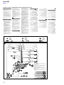
Connection diagram
Italiano
Avvertenza
Advertencia
If you have a power antenna (aerial) without a relay
box, connecting this unit with the supplied power
supply connection cable ʓ may damage the antenna
(aerial).
ɞTo the parking brake switch cord
ˎConecte todos los cables de conexión a masa a un
punto común.
ˎEsta unidad ha sido diseñada para alimentarse sólo
con cc de 12 V de masa negativa.
ˎNo desmonte ni modifique la unidad.
ˎNo la instale en ubicaciones que puedan interferir
con el funcionamiento del airbag.
ˎNo coloque los cables debajo de ningún tornillo, ni
los aprisione con partes móviles (p.ej. los raíles del
asiento).
ˎAntes de realizar las conexiones, desactive el
encendido del vehículo para evitar cortocircuitos.
ˎConecte el cable de suministro de alimentación ʓ a
la unidad y a los altavoces antes de conectarlo al
conector de alimentación auxiliar.
ˎPor razones de seguridad, asegúrese de aislar con
cinta aislante los cables sueltos que no estén
conectados.
ˎNo presione la pantalla de cristal líquido al instalar la
unidad.
Notas sobre el cable de fuente de alimentación
(amarillo)
ˎCuando conecte esta unidad en combinación con
otros componentes estéreo, la capacidad nominal
del circuito del automóvil al que se conecta la
unidad debe ser superior a la suma de la capacidad
nominal de los fusibles de cada componente.
ˎSi no hay circuitos del automóvil con una capacidad
nominal suficientemente alta, conecte la unidad
directamente a la batería.
The mounting position of the parking brake switch cord depends
on your car. For details, see “Connecting the parking brake lead
(Ƕ)” on the reverse side.
Diagrama de conexión
ʭTo an auxiliary device such as a portable
media player, game console, etc. (not
supplied)
Si dispone de una antena motorizada sin caja de relé,
es posible que la conexión de esta unidad mediante el
cable de suministro de alimentación ʓ suministrado
provoque daños en la antena.
Notas sobre los cables de control y de fuente de alimentación
ˎEl cable REM OUT (con rayas azules/blancas) suministrará cc de
+12 V cuando encienda la unidad.
ˎSi utiliza un amplificador de potencia opcional, conecte el cable
REM OUT (con rayas azules/blancas) o el cable de fuente de
alimentación auxiliar (rojo) a su AMP REMOTE IN.
ˎSi su vehículo dispone de una antena motorizada FM/AM
incorporada en el cristal posterior/lateral, conecte el cable REM
OUT (con rayas azules/blancas) o el cable de fuente de
alimentación auxiliar (rojo) al terminal de alimentación del
amplificador de la antena motorizada existente. Para obtener más
información, consulte a su distribuidor oficial.
ˎNo se puede utilizar en esta unidad una antena motorizada sin caja
de relé.
Conexión para protección de la memoria
Si conecta el cable de fuente de alimentación amarillo, el circuito de
la memoria recibirá siempre alimentación, aunque apague el
interruptor de encendido.
Notas sobre la conexión de los altavoces
ˎAntes de conectar los altavoces, desconecte la alimentación de la
unidad.
ˎUtilice altavoces con una impedancia de 4 a 8 ohmios con la
capacidad de potencia adecuada para evitar que se dañen.
ˎNo conecte los terminales de altavoz al chasis del vehículo ni
conecte los terminales de los altavoces derechos a los terminales
de los altavoces izquierdos.
ˎNo conecte el cable de conexión a masa de esta unidad al terminal
negativo (–) de un altavoz.
ˎNo intente conectar los altavoces en paralelo.
ˎConecte solamente altavoces pasivos. Si conecta altavoces activos
(con amplificadores incorporados) a los terminales de altavoz,
puede dañar la unidad.
ˎPara evitar fallos de funcionamiento, no utilice los cables de altavoz
incorporados instalados en el vehículo si tienen un cable negativo
(–) común para los altavoces derecho e izquierdo.
ˎNo conecte los cables de altavoz de la unidad entre sí.
Nota sobre la conexión
Si desea utilizar el monitor para los asientos traseros, conecte el
cable del interruptor del freno de mano a la toma de masa.
ɞAl cable del interruptor del freno de mano
Note sui cavi di controllo e di alimentazione
ˎIl cavo REM OUT (a righe blu/bianche) fornisce alimentazione da
+12 V CC all’accensione dell’apparecchio.
ˎQuando si utilizza un amplificatore di potenza opzionale, collegare
il cavo REM OUT (a righe blu/bianche) o il cavo di alimentazione
accessoria (rosso) al rispettivo AMP REMOTE IN.
ˎSe l’automobile è dotata di antenna FM/AM incorporata nel vetro
posteriore/laterale, collegare il cavo REM OUT (a righe blu/bianche)
o il cavo di alimentazione accessoria (rosso) al terminale di
alimentazione del preamplificatore dell’antenna esistente. Per
ulteriori informazioni, consultare il rivenditore.
ˎNon è possibile usare un’antenna elettrica senza scatola a relè con
questo apparecchio.
Collegamento per la conservazione della memoria
Quando il cavo di ingresso alimentazione giallo è collegato, viene
sempre fornita alimentazione al circuito di memoria anche quando
l’interruttore di accensione è spento.
Note sul collegamento dei diffusori
ˎPrima di collegare i diffusori spegnere l’apparecchio.
ˎUtilizzare diffusori con impedenza compresa tra 4 e 8 ohm e con
capacità di potenza adeguata, altrimenti i diffusori potrebbero
venire danneggiati.
ˎNon collegare i terminali del sistema diffusori al telaio dell’auto e
non collegare i terminali dei diffusori destri a quelli dei diffusori
sinistri.
ˎNon collegare il cavo di terra di questo apparecchio al terminale
negativo (–) di un diffusore.
ˎNon collegare i diffusori in parallelo.
ˎAssicurarsi di collegare soltanto diffusori passivi, poiché il
collegamento di diffusori attivi, dotati di amplificatori incorporati, ai
terminali dei diffusori potrebbe danneggiare l’apparecchio.
ˎPer evitare problemi di funzionamento, non utilizzare i cavi dei
diffusori incorporati installati nell’automobile se l’apparecchio
condivide un cavo comune negativo (–) per i diffusori destro e
sinistro.
ˎNon collegare fra loro i cavi dei diffusori dell’apparecchio.
Note sul cavo di alimentazione (giallo)
ˎSe questo apparecchio viene collegato in
combinazione con altri componenti stereo, la
potenza nominale dei circuiti dell’automobile deve
essere superiore a quella prodotta dalla somma dei
fusibili di ciascun componente.
ˎSe la potenza nominale dei circuiti dell’automobile
non è sufficiente, collegare l’apparecchio
direttamente alla batteria.
Nota sui collegamenti
Se viene utilizzato il monitor per i sedili posteriori, collegare il cavo di
commutazione del freno a mano alla massa (terra).
Schema di collegamento
ɞAl cavo di commutazione del freno a mano
La posizione di montaggio del cavo di commutazione del freno a
mano varia in base all’auto. Per dettagli, consultare
“Collegamento del cavo del freno a mano (Ƕ)” sul lato opposto.
La posición de montaje del cable del interruptor del freno de
mano depende de su vehículo. Para obtener más información,
consulte “Conexión del cable del freno de mano (Ƕ)” en el
reverso.
Tip
You can use an RCA pin cord (not supplied) to connect auxiliary
devices.
ʮTo the +12 V power terminal of the car’s rear
lamp lead (only when connecting the rear
view camera)
Quando si collega l’apparecchio con il cavo di
collegamento dell’alimentazione in dotazione ʓ, si
potrebbe danneggiare l’antenna elettrica, se questa
non dispone di scatola a relé.
Attenzione
ˎPortare tutti i cavi di massa a un punto di massa
comune.
ˎQuesto apparecchio è stato progettato per l’uso solo
a 12 V CC con massa negativa.
ˎNon smontare o modificare l’apparecchio.
ˎNon installare l’apparecchio in luoghi in cui potrebbe
interferire con il funzionamento del sistema airbag.
ˎEvitare che i cavi rimangano bloccati da una vite o
incastrati nelle parti mobili (ad esempio nelle guide
scorrevoli dei sedili).
ˎPrima di effettuare i collegamenti, spegnere il
motore dell’automobile onde evitare di causare
cortocircuiti.
ˎCollegare il cavo di collegamento dell’alimentazione
ʓ all’apparecchio e ai diffusori prima di collegarlo al
connettore di alimentazione ausiliaria.
ˎPer sicurezza, assicurarsi di isolare qualsiasi cavo
non collegato utilizzando del nastro adesivo.
ˎDurante l’installazione dell’apparecchio, prestare
attenzione a non toccare lo schermo LCD.
ʭAll’apparecchio ausiliario, quale ad esempio
un lettore portatile, un dispositivo di gioco e
così via (non in dotazione)
ʭA dispositivos auxiliares, por ejemplo, a un
reproductor multimedia portátil, a una
consola de videojuegos, etc. (no
suministrados)
Suggerimento
È possibile utilizzare un cavo a piedini RCA (non in dotazione)
per collegare i dispositivi ausiliari.
ʮAl terminale di alimentazione da +12 V del
cavo spia della retromarcia dell’auto (solo se
viene collegata la videocamera posteriore)
Sugerencia
Es posible utilizar un cable RCA (no suministrado) para conectar
dispositivos auxiliares.
ʮAl terminal de alimentación de +12 V del
cable de la luz trasera del vehículo
(únicamente cuando se conecta la cámara de
visualización posterior)
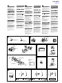
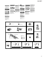
Equipment used in illustrations (not supplied) / Equipo utilizado en las ilustraciones (no suministrado) / Apparecchiatura utilizzata nelle illustrazioni (non in dotazione)
Rear speaker
Altavoz posterior
Diffusore posteriore
Front speaker
Altavoz frontal
Diffusore anteriore
ˬ
Rear view camera
Cámara de visualización posterior
Videocamera posteriore
Power amplifier
Amplificador de potencia
Amplificatore di potenza
Subwoofer
Altavoz potenciador de graves
Subwoofer
Monitor
Monitor
Monitor
For details, see “Power connection diagram” on the reverse side.
Para obtener más información, consulte el “Diagrama de conexión de la alimentación” que encontrará al dorso.
Per ulteriori informazioni, consultare la sezione “Diagramma dei collegamenti di alimentazione” sul lato opposto.
Light green
Verde claro
Verde chiaro
PARKING BRAKE
From the car’s power connector
Desde el conector de alimentación del vehículo
Dal connettore di alimentazione dell’auto
Purple/white striped
Con rayas moradas/blancas
A righe viola/bianche
4
Yellow
Amarillo
Giallo
Continuous power supply
Fuente de alimentación continua
Alimentazione continua
5
Blue/white striped
Con rayas azules/blancas
A righe blu/bianche
Power antenna (aerial)/power amplifier control (REM OUT)
Control del amplificador de potencia/antena motorizada (REM OUT)
Antenna elettrica/controllo dell’amplificatore di potenza (REM OUT)
6
Orange/white
Naranja/blanco
Arancione/bianco
Switched illumination power supply
Fuente de alimentación de iluminación conmutada
Alimentazione illuminazione commutata
7
Red
Rojo
Rosso
Switched power supply
Fuente de alimentación conmutada
Alimentazione commutata
8
Black
Negro
Nero
Ground (earth)
Masa
Terra
Positions 1, 2, and 3 do not have pins.
Las posiciones 1, 2 y 3 no tienen terminales.
Le posizioni 1, 2 e 3 non hanno piedini.
*4
From the car’s speaker connector
Desde el conector de los altavoces del vehículo
Dal connettore del diffusore dell’auto
*1
1
2
ʓ
3
Fuse (10 A)
Fusible (10 A)
Fusibile (10 A)
4
5
6
7
ʙ*5
8
Purple
Morado
Viola
Gray
Gris
Grigio
White
Blanco
Bianco
Green
Verde
Verde
+
Speaker, rear, right
Altavoz, posterior, derecho
Diffusore, posteriore, destro
–
Speaker, rear, right
Altavoz, posterior, derecho
Diffusore, posteriore, destro
+
Speaker, front, right
Altavoz, frontal, derecho
Diffusore, anteriore, destro
–
Speaker, front, right
Altavoz, frontal, derecho
Diffusore, anteriore, destro
+
Speaker, front, left
Altavoz, frontal, izquierdo
Diffusore, anteriore, sinistro
–
Speaker, front, left
Altavoz, frontal, izquierdo
Diffusore, anteriore, sinistro
+
Speaker, rear, left
Altavoz, posterior, izquierdo
Diffusore, posteriore, sinistro
–
Speaker, rear, left
Altavoz, posterior, izquierdo
Diffusore, posteriore, sinistro
Negative polarity positions 2, 4, 6, and 8 have striped leads.
Los cables de las posiciones de polaridad negativa 2, 4, 6 y 8 son rayados.
Le posizioni a polarità negativa 2, 4, 6 e 8 hanno cavi rigati.
From car antenna
(aerial)
Desde la antena del
vehículo
Dall’antenna
dell’auto
*1 RCA pin cord (not supplied)
*2 The supplied cable for Steering Control is connected or a separate adaptor may be required. For details on the connectivity of your
vehicle, visit the support site on the back page of Operation Instructions.
AUDIO OUT can be switched to SUB or REAR. For details, see the supplied Operating Instructions.
Speaker impedance: 4 – 8 ohms × 4
For details on installing the microphone, see “Installing the microphone (ǻ)” on the reverse side.
Whether in use or not, route the microphone input cord such that it does not interfere with driving. Secure the cord with a clamp, etc., if
it is installed around your feet.
*3
*4
*5
*6
*1
*1
*1 Cable con terminales RCA (no suministrado)
*2 El cable suministrado para el Ctrl. en el volante está conectado o es posible que se necesite un adaptador independiente. Para obtener
información detallada sobre la conectividad del vehículo, visite el sitio de soporte que aparece en el reverso del Manual de instrucciones.
*3 AUDIO OUT se puede cambiar a SUB o REAR. Para obtener información, consulte el Manual de instrucciones suministrado.
*4 Impedancia del altavoz: 4 – 8 Ω × 4
*5 Para obtener más información acerca de la instalación del micrófono, consulte “Instalación del micrófono (ǻ)” en el reverso.
*6 Independientemente de si va a utilizarlo, pase el cable de entrada del micrófono de modo que no obstaculice las maniobras de
conducción. Fije el cable con una abrazadera o mecanismo similar si lo instala en la zona de los pies.
*1 Cavo a piedini RCA (non in dotazione)
*2 Il cavo in dotazione per Steering Control (controllo sterzo) è connesso oppure è necessario un adattatore separato. Per informazioni
dettagliate sui collegamenti del proprio veicolo, visitare il sito di assistenza riportato sulla retrocopertina delle Istruzioni per l’uso.
*3 AUDIO OUT può essere commutato su SUB o REAR. Per ulteriori informazioni, consultare le Istruzioni per l’uso in dotazione.
*4 Impedenza diffusori: da 4 a 8 ohm × 4
*5 Per ulteriori informazioni sull’installazione del microfono, consultare la sezione “Installazione del microfono (ǻ)” sul lato opposto.
*6 Indipendentemente dal fatto che venga utilizzato o meno, sistemare il cavo di ingresso del microfono in modo che non interferisca con
la guida. Se il cavo è installato nella parte dell’abitacolo riservato ai piedi, fissarlo con un fermacavo o simili.
8
XAV-68BT
Ver. 1.3
English
Español
Warning if your car’s ignition has
no ACC position
Precautions
ˎChoose the installation location carefully so that the
unit will not interfere with normal driving operations.
ˎAvoid installing the unit in areas subject to dust, dirt,
excessive vibration, or high temperature, such as in
direct sunlight or near heater ducts.
ˎUse only the supplied mounting hardware for a safe
and secure installation.
Reset button
When the installation and connections are completed,
be sure to press the reset button with a ballpoint pen,
etc.
Mounting angle adjustment
Adjust the mounting angle to less than 45°.
Connecting the parking brake
lead
Installing the microphone
Caution
Handle the bracket ʖ carefully to avoid injuring your
fingers.
1
2
Remove the pre-installed screws.
3
Pull down the bracket ʖ, then pull up the unit to
separate them.
Insert the release keys ʗ into the catches
between the unit and the bracket ʖ at the same
time until they click.
Mounting the unit
Ǹ-A Mounting the unit with the supplied
bracket
1
Position the supplied bracket ʖ inside the
dashboard.
3
4
Bend the claws outward for a tight fit.
1
2
Extraiga los tornillos preinstalados.
ǻ-A Installing on the sun visor
Install clips (not supplied) and adjust the length and
position of the cord so that it does not obstruct your
driving.
3
Presione el soporte ʖ y, a continuación, levante
la unidad para separar ambos elementos.
Mount the unit onto the supplied bracket ʖ.
Note
If the catches are straight or bent outwards, the unit will not be
installed securely and may spring out.
Power connection diagram
The auxiliary power connector may vary depending on
your car. Check your car’s auxiliary power connector
diagram to make sure the connections match
correctly. There are three basic types (Ǽ-A, Ǽ-B,
Ǽ-C). You may need to switch the positions of the red
and yellow leads of the unit’s power supply
connection cable ʓ. After matching the connections
and switched power supply leads correctly, connect
the unit to the car’s power supply. If you have any
questions and problems connecting your unit that are
not covered in these instructions, please consult your
car dealer.
Ǹ-B Mounting the unit in a Japanese car
You may be able to install this unit in some makes of
Japanese cars without the supplied bracket. If you
cannot, consult your Sony dealer.
When mounting this unit to the preinstalled brackets
of your car, use the supplied screws ʕ in the
appropriate screw holes, based on your car: T for
TOYOTA, M for MITSUBISHI and N for NISSAN.
1
Antes de instalar la unidad, compruebe que los
enganches de ambos lados del soporte ʖ están
doblados hacia adentro 3,5 mm.
2
Coloque el soporte suministrado ʖ dentro del
salpicadero.
3
Doble los ganchos hacia fuera para conseguir
una fijación segura.
4
Monte la unidad en el soporte suministrado ʖ.
Rimuovere le viti preinstallate.
Inserire le chiavette di rilascio ʗ nei fermi tra
l’apparecchio e la staffa ʖ contemporaneamente
fino a che non scattano in posizione.
Estrarre la staffa ʖ, quindi sollevare
l’apparecchio per rimuoverlo.
3
ǻ-A Installazione sull’aletta parasole
Montaggio dell’apparecchio
Instale un clip (no suministrado) y ajuste la longitud y
la posición del cable para evitar que obstaculice la
conducción.
1
Prima di installare l’apparecchio, accertarsi di
ripiegare i fermi presenti su entrambi i lati della
staffa ʖ verso l’interno di 3,5 mm.
Notas
ˎAntes de colocar la cinta adhesiva de doble cara , limpie la
superficie del salpicadero con un paño seco.
ˎAjuste el ángulo del micrófono en la posición adecuada.
2
3
Installare la staffa in dotazione ʖ nel cruscotto.
4
Montare l’apparecchio sulla staffa in dotazione
ʖ.
Diagrama de conexión de la
alimentación
Es posible que pueda instalar esta unidad en algunos
vehículos de marcas japonesas sin necesidad de
utilizar el soporte suministrado. En caso de que no
pueda, póngase en contacto con el distribuidor de
Sony.
Para montar esta unidad en los soportes preinstalados
del vehículo, utilice los tornillos ʕ suministrados en
los orificios para tornillos correspondientes en función
de su automóvil: T corresponde a TOYOTA, M a
MITSUBISHI y N a NISSAN.
Notas
ˎPara evitar fallos de funcionamiento, realice la instalación
únicamente con los tornillos suministrados ʕ.
ˎNo ejerza presión excesiva sobre los botones de la unidad.
ˎNo ejerza presión sobre la pantalla de cristal líquido.
ˎAntes de efectuar el montaje, asegúrese de que no haya ningún
objeto en la parte superior de la unidad.
Note
ˎPrima di applicare il nastro biadesivo , pulire la superficie del
cruscotto con un panno asciutto.
ˎRegolare l’angolazione del microfono sulla posizione corretta.
Diagramma dei collegamenti di
alimentazione
Il connettore di alimentazione ausiliaria può variare a
seconda della macchina. Controllare il diagramma del
connettore di alimentazione ausiliaria dell’auto per
assicurarsi che i collegamenti corrispondano
correttamente. Vi sono tre tipi di base (Ǽ-A, Ǽ-B,
Ǽ-C). Potrebbe essere necessario cambiare le
posizioni dei fili rosso e giallo del cavo di
collegamento dell’alimentazione dell’apparecchio ʓ.
Dopo aver fatto corrispondere i collegamenti e aver
commutato correttamente i cavi di alimentazione,
collegare l’apparecchio all’alimentazione della
macchina. In caso di domande o se sorgono problemi
relativi al collegamento dell’apparecchio che non sono
stati trattati nel presente manuale, contattare
l’autoconcessionario.
Ǹ-B Montaggio in un’auto giapponese
È possibile installare il presente apparecchio in alcuni
tipi di auto giapponesi senza utilizzare la staffa in
dotazione. In caso contrario, rivolgersi al rivenditore
Sony autorizzato.
Durante il montaggio del presente apparecchio sulle
staffe preinstallate dell’auto, inserire le viti in
dotazione ʕ negli appositi fori, in base al modello
dell’auto: T per TOYOTA, M per MITSUBISHI e N per
NISSAN.
Note
ˎEffettuare l’installazione utilizzando esclusivamente le viti in
dotazione ʕ, onde evitare problemi di funzionamento.
ˎNon applicare forza eccessiva sui tasti dell’apparecchio.
ˎNon premere sullo schermo LCD.
ˎPrima del montaggio, accertarsi che sulla parte superiore
dell’apparecchio non vi sia alcun oggetto.
ʗ
Face the hook inwards.
Oriente el gancho hacia dentro.
Con il gancetto rivolto verso l’interno.
q
q
Parking brake switch cord
Cable del interruptor del freno de mano
Cavo di commutazione del freno a mano
Catch
Enganche
Fermo
˯A
Installare un fermaglio (non in dotazione) e regolare la
lunghezza e la posizione del cavo in modo che non
ostacoli la guida.
Nota
Se i fermi sono diritti o ripiegati verso l’esterno, l’apparecchio non
verrà installato in modo sicuro e potrebbe fuoriuscire.
ˮ
Parking brake switch cord
Cable del interruptor del freno de mano
Cavo di commutazione del freno a mano
ǻ-B Installazione sul cruscotto
Piegare i morsetti verso l’esterno per
un’applicazione più stabile.
Hand brake type
Freno de mano
Tipo freno a mano
Foot brake type
Freno de pedal
Tipo freno a pedale
Installare i fermagli (non in dotazione) e regolare la
lunghezza e la posizione del cavo in modo che non
ostacoli la guida.
Ǹ-A Montare l’apparecchio utilizzando la
staffa in dotazione
El conector de alimentación auxiliar puede variar
según el vehículo. Consulte el diagrama de conexión
de la alimentación auxiliar del vehículo para
asegurarse de que realiza las conexiones
correctamente. Hay tres tipos básicos de diagramas
(Ǽ-A, Ǽ-B, Ǽ-C). Es posible que deba intercambiar
las posiciones de los cables rojo y amarillo del cable
de suministro de alimentación de la unidad ʓ. Una
vez que haya realizado las conexiones de los cables
de la fuente de alimentación conmutada
correctamente, conecte la unidad a la alimentación
del vehículo. Si desea realizar alguna consulta o
solucionar algún problema relativo a la conexión de la
unidad que no se trate en este manual, póngase en
contacto con el concesionario en el que ha adquirido
el vehículo.
Ǹ-B Montaje de la unidad en un vehículo
japonés
˭
1
2
ǻ-B Instalación en el salpicadero
Nota
Si los enganches están rectos o doblados hacia fuera, la unidad no se
instalará correctamente y puede saltar.
Notes
ˎTo avoid a malfunction, install only with the supplied screws ʕ.
ˎDo not apply excessive force to the buttons of the unit.
ˎDo not press on the LCD.
ˎBefore mounting, make sure there is nothing on the top of the unit.
Attenzione
ˎNon sottoporre il microfono a temperature e umidità
eccessivamente elevate.
ˎSe il cavo rimane avvolto al piantone di guida o alla
leva del cambio, possono verificarsi situazioni di
pericolo. Accertarsi di posizionare il cavo e altre parti
in modo che non ostruiscano la guida.
ˎSe nell’auto sono presenti air-bag o altri dispositivi
di assorbimento degli urti, prima dell’installazione
contattare il negozio in cui è stato acquistato
l’apparecchio o l’autoconcessionario.
Attenzione
Maneggiare la staffa ʖ con cautela per evitare di
ferirsi le mani.
Instale los clips (no suministrados) y ajuste la longitud
y la posición del cable para evitar que obstaculice la
conducción.
Ǹ-A Montaje de la unidad con el soporte
suministrado
Notes
ˎBefore attaching the double-sided tape , clean the surface of the
dashboard with a dry cloth.
ˎAdjust the microphone angle to the proper position.
Per catturare la voce durante le chiamate in vivavoce,
è necessario installare il microfono ͬ.
ǻ-A Instalación en la visera
Montaje de la unidad
Install a clip (not supplied) and adjust the length and
position of the cord so that it does not obstruct your
driving.
Installazione del microfono
Prima di installare l’apparecchio, rimuovere la staffa
ʖ dall’apparecchio.
Conservare le chiavette di rilascio ʗ per un uso
futuro in quanto sono necessarie per rimuovere
l’apparecchio dall’auto.
Precauciones
ˎMantenga el micrófono alejado de lugares con
humedad y temperaturas muy altas.
ˎQue el cable se enrolle alrededor de la columna de
dirección o de la palanca de cambios es
extremadamente peligroso. Asegúrese de impedir
que el cable y otros componentes obstruyan la
conducción.
ˎSi el vehículo dispone de airbags u otros dispositivos
de amortiguación de impactos, póngase en contacto
con el establecimiento donde ha adquirido esta
unidad o con el concesionario de automóviles antes
de llevar a cabo la instalación.
Inserte las llaves de liberación ʗ en los
enganches entre la unidad y el soporte ʖ al
mismo tiempo hasta que escuche un clic.
Per la sostituzione del fusibile, assicurarsi di utilizzare
un fusibile dello stesso amperaggio di quello indicato
sull’originale. Se il fusibile si brucia, controllare i
collegamenti dell’alimentazione e sostituire il fusibile.
Se dopo la sostituzione il fusibile si brucia di nuovo, è
possibile che si tratti di un problema interno. In tal
caso, rivolgersi al più vicino rivenditore Sony.
Rimozione della staffa
Para capturar su voz durante las llamadas con manos
libres, es necesario instalar el micrófono ʙ.
Precaución
Tenga mucho cuidado al manipular el soporte ʖ para
evitar posibles lesiones en los dedos.
Sostituzione del fusibile
Collegamento del cavo del freno
a mano
Assicurarsi di collegare il cavo del freno a mano (verde
chiaro) del cavo di collegamento dell’alimentazione ʓ
al cavo di commutazione del freno a mano.
Instalación del micrófono
Antes de instalar la unidad, extraiga el soporte ʖ
de la unidad.
Guarde las llaves de liberación ʗ para utilizarlas en
el futuro, ya que también son necesarias para
extraer la unidad del vehículo.
ǻ-B Installing on the dashboard
Before installing, make sure that the catches on
both sides of the bracket ʖ are bent inwards 3.5
mm.
2
Extracción del soporte
Cautions
ˎKeep the microphone away from extremely high
temperatures and humidity.
ˎIt is extremely dangerous if the cord becomes
wound around the steering column or gearstick. Be
sure to keep it and other parts from obstructing your
driving.
ˎIf airbags or any other shock-absorbing equipment
is in your car, contact the store where you purchased
this unit, or the car dealer, before installation.
Tasto di azzeramento
Una volta completate le procedure di installazione e i
collegamenti, accertarsi di premere il tasto di
azzeramento con una penna a sfera o un oggetto
simile.
Regolare l’angolo di montaggio in modo che sia
inferiore a 45°.
Sustitución del fusible
Al sustituir el fusible, asegúrese de utilizar uno cuyo
amperaje coincida con el especificado en el original. Si
el fusible se funde, verifique la conexión de
alimentación y sustitúyalo. Si el fusible vuelve a
fundirse después de sustituirlo, es posible que exista
algún fallo de funcionamiento interno. En tal caso,
consulte con el distribuidor Sony más cercano.
Asegúrese de conectar el cable del freno de mano (de
color verde claro) del cable de suministro de
alimentación ʓ al cable del interruptor del freno de
mano.
To capture your voice during handsfree calling, you
need to install the microphone ͬ.
Dopo aver spento l’auto, accertarsi di tenere premuto
OFF sull’unità finché il display non si disattiva.
In caso contrario, il display non si spegne e ciò causa
l’esaurimento della batteria.
Regolazione dell’angolo di montaggio
Conexión del cable del freno de
mano
Removing the bracket
Before installing the unit, remove the bracket ʖ
from the unit.
Keep the release keys ʗ for future use as they are
also necessary if you remove the unit from your car.
Botón de reinicio
Una vez finalizadas la instalación y las conexiones,
asegúrese de presionar el botón de reinicio con un
bolígrafo, etc.
Ajuste el ángulo de montaje a menos de 45°.
When replacing the fuse, be sure to use one matching
the amperage rating stated on the original fuse. If the
fuse blows, check the power connection and replace
the fuse. If the fuse blows again after replacement,
there may be an internal malfunction. In such a case,
consult your nearest Sony dealer.
Be sure to connect the parking brake lead (light green)
of the power supply connection cable ʓ to the
parking brake switch cord.
Precauzioni
ˎScegliere con attenzione la posizione per
l’installazione in modo che l’apparecchio non
interferisca con le operazioni di guida del
conducente.
ˎEvitare di installare l’apparecchio dove sia soggetto
ad alte temperature, come alla luce solare diretta o
al getto di aria calda dell’impianto di riscaldamento,
o dove possa essere soggetto a polvere, sporcizia e
vibrazioni eccessive.
ˎUsare solo il materiale di montaggio in dotazione
per un’installazione stabile e sicura.
Después de desactivar el encendido, asegúrese de
mantener pulsado OFF en la unidad hasta que la
pantalla desaparezca.
De lo contrario, la pantalla no se apagará y esto
provocará que se desgaste la batería.
Ajuste del ángulo de montaje
Fuse replacement
Avvertenza relativa
all’installazione su un’auto
sprovvista della posizione ACC
(accessoria) sul blocchetto di
accensione
Italiano
Advertencia: si el encendido del
vehículo no dispone de una
posición ACC
Precauciones
ˎElija cuidadosamente el lugar de montaje de forma
que la unidad no interfiera con las funciones
normales de conducción.
ˎEvite instalar la unidad donde pueda quedar
sometida a polvo, suciedad, vibraciones excesivas o
altas temperaturas como, por ejemplo, a la luz solar
directa o cerca de conductos de calefacción.
ˎPara realizar una instalación segura y firme, utilice
solamente los componentes de montaje
suministrados.
After turning the ignition off, be sure to press and hold
OFF on the unit until the display disappears.
Otherwise, the display does not turn off and this
causes battery drain.
ʖ
˲A
˰
Larger than 182 mm
De longitud superior a 182 mm
Superiore a 182 mm
Dashboard
Salpicadero
Cruscotto
Larger than 111 mm
De longitud superior a 111 mm
Superiore a 111 mm
q
ʘ
Claws
Ganchos
Morsetti
ʖ
Catch
Enganche
Fermo
Clips (not supplied)
Clips (no suministrados)
Fermagli (non in dotazione)
B
Size:
5 × max. 8 mm
Tamaño:
5 × máx. 8 mm
Dimensioni:
5 × max. 8 mm
To the dashboard/center console
Al salpicadero o consola central
Al cruscotto/alla console centrale
Location of screw holes
Posición de los orificios de los tornillos
Posizione dei fori per le viti
T: TOYOTA
M: MITSUBISHI
N: NISSAN
Bracket
Soporte
Staffa
Parts supplied with your car
Piezas suministradas con su automóvil
Parti in dotazione con l’auto
Fuse (10 A)
Fusible (10 A)
Fusibile (10 A)
ʕ
Size:
5 × max. 8 mm
Tamaño:
5 × máx. 8 mm
Dimensioni:
5 × max. 8 mm
Bracket
Soporte
Staffa
˳
B
˱
ʕ
Clip (not supplied)
Clip (no suministrado)
Fermaglio (non in dotazione)
A
B
C
Red
Rojo
Rosso
Red
Rojo
Rosso
Red
Rojo
Rosso
Red
Rojo
Rosso
Red
Rojo
Rosso
Red
Rojo
Rosso
Yellow
Amarillo
Giallo
Yellow
Amarillo
Giallo
Yellow
Amarillo
Giallo
Yellow
Amarillo
Giallo
Yellow
Amarillo
Giallo
Yellow
Amarillo
Giallo
Auxiliary power connector
Conector de alimentación auxiliar
Connettore di alimentazione ausiliaria
4
Yellow
Amarillo
Giallo
Continuous power supply
Fuente de alimentación continua
Alimentazione continua
7
Red
Rojo
Rosso
Switched power supply
Fuente de alimentación conmutada
Alimentazione commutata
4
Yellow
Amarillo
Giallo
Switched power supply
Fuente de alimentación conmutada
Alimentazione commutata
7
Red
Rojo
Rosso
Continuous power supply
Fuente de alimentación continua
Alimentazione continua
A car without an ACC position
Vehículo sin posición ACC
Auto priva della posizione ACC
9
XAV-68BT
Ver. 1.1
(E (NTSC), E (PAL), Saudi Arabia, Indian and Australian models)
Cautions
ˎRun all ground (earth) leads to a common ground
(earth) point.
ˎThis unit is designed for negative ground (earth) 12 V
DC operation only.
ˎDo not disassemble or modify the unit.
ˎDo not install in locations which interfere with airbag
operation.
ˎDo not get the leads under a screw, or caught in
moving parts (e.g. seat railing).
ˎBefore making connections, turn the car ignition off
to avoid short circuits.
ˎConnect the yellow and red power supply leads
only after all other leads have been connected.
ˎBe sure to insulate any loose unconnected leads
with electrical tape for safety.
ˎDo not press on the LCD when installing the unit.
Notes on the power supply lead (yellow)
ˎWhen connecting this unit in combination with other
stereo components, the amperage rating of the car
circuit to which the unit is connected must be higher
than the sum of each component's fuse amperage
rating.
ˎIf no car circuits are rated high enough, connect the
unit directly to the battery.
Memory hold connection
When the yellow power supply lead is connected, power will always
be supplied to the memory circuit even when the ignition switch is
turned off.
Notes on speaker connection
ˎBefore connecting the speakers, turn the unit off.
ˎUse speakers with an impedance of 4 to 8 ohms, and with
adequate power handling capacities to avoid damage.
ˎDo not connect the speaker terminals to the car chassis, or connect
the terminals of the right speakers with those of the left speakers.
ˎDo not connect the ground (earth) lead of this unit to the negative
(–) terminal of a speaker.
ˎDo not attempt to connect the speakers in parallel.
ˎConnect only passive speakers. Connecting active speakers (with
built-in amplifiers) to the speaker terminals may damage the unit.
ˎTo avoid a malfunction, do not use the built-in speaker leads
installed in your car if they feature a common negative (–) lead for
the right and left speakers.
ˎDo not connect the unit’s speaker leads to each other.
First connect the black ground (earth) lead, then connect the
yellow and red power supply leads.
ɟTo the power antenna (aerial) control lead or
the power supply lead of the antenna (aerial)
booster
Notes
ˎIt is not necessary to connect this lead if there is no power
antenna (aerial) or antenna (aerial) booster, or with a
manually-operated telescopic antenna (aerial).
ˎIf your car has a built-in FM/AM antenna (aerial) in the rear/
side glass, see “Notes on the control and power supply leads.”
To AMP REMOTE IN of an optional power
amplifier
This connection is only for amplifiers. Connecting any other
system may damage the unit.
ɠTo a car’s illumination signal
Be sure to first connect the black ground (earth) lead to a
common ground (earth) point.
ɡTo the +12 V power terminal which is
energized when the ignition switch is set to
the accessory position
Notes
ˎIf there is no accessory position, connect to the +12 V power
(battery) terminal which is energized at all times.
Be sure to first connect the black ground (earth) lead to a
common ground (earth) point.
ˎIf your car has a built-in FM/AM antenna (aerial) in the rear/
side glass, see “Notes on the control and power supply leads.”
ɢTo the +12 V power terminal which is
energized at all times
Be sure to first connect the black ground (earth) lead to a
common ground (earth) point.
ɣTo the parking brake switch cord
The mounting position of the parking brake switch cord depends
on your car. For details, see “Connecting the parking brake lead
(Ƕ)” on the reverse side.
ʭTo an auxiliary device such as a portable
media player, game console, etc. (not
supplied)
A AMP REMOTE IN de un amplificador de
potencia opcional
ɡAl terminal de alimentación de +12 V que
recibe energía en la posición de accesorio del
interruptor de la llave de encendido
Notas
ˎSi no hay posición de accesorio, conéctelo al terminal de
alimentación (batería) de +12 V que recibe energía sin
interrupción.
Asegúrese de conectar primero el cable negro de conexión a
masa a un punto de conexión a masa común.
ˎSi el automóvil tiene una antena FM/AM integrada en el cristal
posterior o lateral, consulte las “Notas sobre los cables de
control y de fuente de alimentación”.
اﻟﻨﺸﻂ اﻻﺧﺘﻴﺎري
اﻟﻘﻴﺎم ﺑﺘﻮﺻﻴﻞ أي ﻧﻈﺎم.ﻫﺬا اﻟﺘﻮﺻﻴﻞ ﺧﺎص ﺑﻤﻀﺨﻤﺎت اﻟﺼﻮت ﻓﻘﻂ
.آﺧﺮ ﻗﺪ ﻳﺘﻠﻒ اﻟﺠﻬﺎز
إﻟﻰ إﺷﺎرة إﺿﺎءة اﻟﺴﻴﺎرةɠ
.أوﻻ إﻟﻰ ﻧﻘﻄﺔ ﺗﺄرﻳﺾ ﻣﺸﺘﺮﻛﺔ
ً ﺗﺄﻛﺪ ﻣﻦ ﺗﻮﺻﻴﻞ ﺳﻠﻚ اﻟﺘﺄرﻳﺾ اﻷﺳﻮد
ﻓﻮﻟﻂ اﻟﺬي ﻳﺴﺮي ﻓﻴﻪ اﻟﺘﻴﺎر ﻋﻨﺪﻣﺎ+12 إﻟﻰ ﻃﺮف ﺗﻮﺻﻴﻞ اﻟﻄﺎﻗﺔɡ
ﻳﻜﻮن ﻣﻔﺘﺎح إﺷﻌﺎل اﻟﻤﺤﺮك ﻓﻲ ﻣﻮﺿﻊ اﻟﻜﻤﺎﻟﻴﺎت
Asegúrese de conectar primero el cable negro de conexión a
masa a un punto de conexión a masa común.
ɣ Al cable de conmutación del freno de
estacionamiento
ˎConecte todos los cables de conexión a masa a un
punto común.
ˎEsta unidad ha sido diseñada para alimentarse
solamente con cc de 12 V de masa negativa.
ˎNo desmonte ni modifique la unidad.
ˎNo instale la unidad en lugares en los que interfiera
con el funcionamiento del airbag.
ˎNo coloque los cables debajo de ningún tornillo, ni
los aprisione con partes móviles (p. ej. los raíles del
asiento).
ˎAntes de realizar las conexiones, desactive el
encendido del automóvil para evitar cortocircuitos.
ˎConecte los cables de fuente de alimentación
amarillo y rojo solamente después de haber
conectado los demás.
ˎPor razones de seguridad, asegúrese de aislar con
cinta aislante los cables sueltos que no estén
conectados.
ˎNo presione la pantalla LCD cuando instale la
unidad.
La posición de montaje del cable de conmutación del freno de
estacionamiento depende del automóvil. Para obtener detalles,
vea la sección “Conexión del cable del freno de estacionamiento
(Ƕ)” del lado reverso.
ʭA un dispositivo auxiliar, como, por ejemplo,
un reproductor portátil, una consola de
videojuegos, etc. (no suministrados)
Sugerencia
Es posible utilizar el cable con terminales RCA (no suministrado)
para conectar dispositivos auxiliares.
ʮAl terminal de alimentación de +12 V del
cable del indicador posterior del automóvil
(únicamente cuando conecte la cámara
retrovisora)
Notas sobre los cables de control y de fuente de alimentación
ˎEl cable REM OUT (rayado azul y blanco) suministra cc +12 V al
encender la unidad.
ˎSi el automóvil dispone de una antena de FM/AM incorporada en el
cristal trasero o lateral, conecte el cable REM OUT (rayado azul y
blanco) o el cable de fuente de alimentación auxiliar (rojo) al
terminal de alimentación del amplificador de señal de la antena
existente. Para obtener más detalles, consulte a su distribuidor.
ˎCon esta unidad no es posible utilizar una antena motorizada sin
caja de relé.
Notas sobre el cable de fuente de alimentación
(amarillo)
ˎCuando conecte esta unidad en combinación con
otros componentes estéreo, la capacidad nominal
del circuito conectado del automóvil debe ser
superior a la suma del fusible de cada componente.
ˎSi no hay circuitos del automóvil con capacidad
nominal suficientemente alta, conecte la unidad
directamente a la batería.
Conecte primero el cable negro de conexión a masa, y después
los cables rojo y amarillo de fuente de alimentación.
Tip
You can use an RCA pin cord (not supplied) to connect auxiliary
devices.
ʮTo the +12 V power terminal of the car’s rear
lamp lead (only when connecting the rear
view camera)
ﻧﮑﺎﺗﯽ درﺑﺎره اﺗﺼﺎل
( ﺳﯿﻢ ﺳﻮﺋﯿﭻ ﺗﺮﻣﺰ دﺳﺘﯽ را ﺑﻪ زﻣﯿﻦ )ارت،ﺟﻬﺖ اﺳﺘﻔﺎده از ﻣﺎﻧﯿﺘﻮر ﺑﺮای ﺻﻨﺪﻟﯽ ﻫﺎی ﻋﻘﺐ
.وﺻﻞ ﮐﻨﯿﺪ
اﻟﻌﺮﺑﻴﺔ
ﺗﻨﺒﻴﻬﺎت
ˎﻗﻢ ﺑﺘﻤﺮﻳﺮ ﺟﻤﻴﻊ أﺳﻼك اﻟﺘﺄرﻳﺾ إﻟﻰ ﻧﻘﻄﺔ ﺗﺄرﻳﺾ ﻣﺸﺘﺮﻛﺔ
. ﻓﻮﻟﻂ ﺑﺘﺄرﻳﺾ ﺳﺎﻟﺐ ﻓﻘﻂ12 ˎﻫﺬه اﻟﻮﺣﺪة ﻣﺼﻤﻤﺔ ﻟﻠﺘﺸﻐﻴﻞ ﺑﺘﻴﺎر ﻣﺒﺎﺷﺮ
.ˎﻻ ﺗﻘﻢ ﺑﻔﻚ اﻟﺠﻬﺎز أو ﺗﻌﺪﻳﻠﻪ
.ˎﻻ ﺗﻘﻢ ﺑﺎﻟﺘﺮﻛﻴﺐ ﻓﻲ اﻷﻣﺎﻛﻦ اﻟﺘﻲ ﺗﺘﺪاﺧﻞ ﻣﻊ وﻇﻴﻔﺔ أﻛﻴﺎس اﻟﻬﻮاء
أو ﺗﻼﻣﺲ اﻷﺟﺰاء اﻟﻤﺘﺤﺮﻛﺔ )ﻋﻠﻰ ﺳﺒﻴﻞ،ˎﻻ ﺗﺪع اﻷﺳﻼك ﺗﻤﺮ ﻣﻦ ﺗﺤﺖ ﺑﺮﻏﻲ
.( ﻗﻀﺒﺎن ﺗﺤﺮﻳﻚ اﻟﻤﻘﻌﺪ،اﻟﻤﺜﺎل
أﻃﻔﺊ ﻣﻔﺘﺎح إﺷﻌﺎل اﻟﻤﺤﺮك ﻟﺘﻔﺎدي ﺣﺪوث ﺗﻤﺎس،ˎﻗﺒﻞ ﺗﻨﻔﻴﺬ اﻟﺘﻮﺻﻴﻼت
.ﻛﻬﺮﺑﻲ
ˎﻗﻢ ﺑﺘﻮﺻﻴﻞ أﺳﻼك دﺧﻞ اﻟﻄﺎﻗﺔ اﻷﺻﻔﺮ واﻷﺣﻤﺮ ﻓﻘﻂ ﺑﻌﺪ اﻻﻧﺘﻬﺎء ﻣﻦ
.ﺗﻮﺻﻴﻞ اﻷﺳﻼك اﻷﺧﺮى
ˎﺗﺄﻛﺪ ﻣﻦ ﻋﺰل أي ارﺗﺨﺎء ﻓﻲ اﻷﺳﻼك ﻏﻴﺮ اﻟﻤﻮﺻﻮﻟﺔ ﺑﺎﺳﺘﻌﻤﺎل ﺷﺮﻳﻂ
.ﻛﻬﺮﺑﺎﺋﻲ ﻟﻀﻤﺎن اﻟﺴﻼﻣﺔ
. ﻋﻨﺪ ﺗﺮﻛﻴﺐ اﻟﺠﻬﺎزLCD ˎﻻ ﺗﻀﻐﻂ ﻋﻠﻰ
ﺗﻮﺟﻴﻪ
)ﻏﻴﺮ ﻣﺮﻓﻖ( ﻟﺘﻮﺻﻴﻞ اﻷﺟﻬﺰةRCA ﻳﻤﻜﻨﻚ اﺳﺘﺨﺪام ﺳﻠﻚ دﺑﻮﺳﻲ
اﻟﻤﺴﺎﻋﺪة
ﻓﻮﻟﻂ ﻷﺳﻼك ﻣﺼﺒﺎح اﻟﺴﻴﺎرة اﻟﺨﻠﻔﻲ+12 إﻟﻰ ﻃﺮف ﺗﻮﺻﻴﻞ اﻟﻄﺎﻗﺔʮ
()ﻓﻘﻂ ﻋﻨﺪ ﺗﻮﺻﻴﻞ اﻟﻜﺎﻣﻴﺮا اﻟﺨﻠﻔﻴﺔ
ﻣﻼﺣﻈﺎت ﺣﻮل أﺳﻼك اﻟﺘﺤﻜﻢ وإﻣﺪاد اﻟﻄﺎﻗﺔ
. ﻓﻮﻟﻂ ﻋﻨﺪﻣﺎ ﺗﺸﻐﻞ اﻟﺠﻬﺎز+12 أﺑﻴﺾ( ﺑﺘﻴﺎر ﻣﺒﺎﺷﺮ/ )ﻣﺨﻄﻂ أزرقREM OUT ˎﺗﺰود أﺳﻼك
ﻓﻘﻢ،اﻟﺠﺎﻧﺒﻲ/ داﺧﻠﻲ ﻣﺮﻛﺐ ﻓﻲ اﻟﺰﺟﺎج اﻟﺨﻠﻔﻲFM/AM ˎإذا ﻛﺎﻧﺖ ﺳﻴﺎرﺗﻚ ﻣﺠﻬﺰة ﺑﻬﻮاﺋﻲ
(أﺑﻴﺾ( أو ﺳﻠﻚ إﻣﺪاد اﻟﻄﺎﻗﺔ ﻟﻠﻜﻤﺎﻟﻴﺔ )أﺣﻤﺮ/ )ﻣﺨﻄﻂ أزرقREM OUT ﺑﺘﻮﺻﻴﻞ ﺳﻠﻚ
. اﺳﺘﺸﺮ اﻟﻮﻛﻴﻞ، ﻟﻠﺘﻔﺎﺻﻴﻞ.أﺻﻼ
ً إﻟﻰ ﻃﺮف ﺗﻮﺻﻴﻞ اﻟﻄﺎﻗﺔ ﻟﻤﻌﺰز اﻟﻬﻮاﺋﻲ اﻟﻤﻮﺟﻮد
.ˎﻻ ﻳﻤﻜﻦ اﺳﺘﻌﻤﺎل اﻟﻬﻮاﺋﻲ اﻵﻟﻲ اﻟﺬي ﻻ ﻳﺤﺘﻮي ﻋﻠﻰ ﺻﻨﺪوق ﻣﻨﺎوﺑﺔ ﻓﻲ ﻫﺬا اﻟﺠﻬﺎز
(ﻣﻼﺣﻈﺎت ﺣﻮل ﺳﻠﻚ إﻣﺪاد اﻟﻄﺎﻗﺔ )أﺻﻔﺮ
ﻳﺠﺐ أن،ˎﻋﻨﺪ ﺗﻮﺻﻴﻞ ﻫﺬه اﻟﻮﺣﺪة ﺑﺎﻻﺷﺘﺮاك ﻣﻊ ﻣﻜﻮﻧﺎت ﺳﺘﻴﺮﻳﻮ أﺧﺮى
ﺗﻜﻮن ﻣﻌﺎﻳﺮة داﺋﺮة اﻟﺴﻴﺎرة اﻟﻤﻮﺻﻮﻟﺔ أﻋﻠﻰ ﻣﻦ ﻣﻘﺪار ﻛﻞ ﻓﻴﻮز ﻣﻦ ﻓﻴﻮزات
.اﻟﻤﻜﻮﻧﺎت
ﻗﻢ،ˎﻋﻨﺪﻣﺎ ﻻ ﺗﻮﺟﺪ دواﺋﺮ ﻓﻲ اﻟﺴﻴﺎرة ﻣﻌﺎﻳﺮة ﺑﻤﻘﺪار ﻣﺮﺗﻔﻊ ﺑﻤﺎ ﻓﻴﻪ اﻟﻜﻔﺎﻳﺔ
.ﺑﺘﻮﺻﻴﻞ اﻟﺠﻬﺎز إﻟﻰ اﻟﺒﻄﺎرﻳﺔ ﻣﺒﺎﺷﺮة
ﺗﻮﺻﻴﻞ ﺣﻔﻆ اﻟﺬاﻛﺮة
ﺳﻴﺘﻢ إﻣﺪاد اﻟﻄﺎﻗﺔ إﻟﻰ داﺋﺮة اﻟﺬاﻛﺮة أﻳﻀً ﺎ ﺣﺘﻰ ﻋﻨﺪﻣﺎ،ﻋﻨﺪ ﺗﻮﺻﻴﻞ ﺳﻠﻚ دﺧﻞ اﻟﻄﺎﻗﺔ اﻷﺻﻔﺮ
.ﻳﻜﻮن ﻣﻔﺘﺎح إﺷﻌﺎل اﻟﻤﺤﺮك ﻓﻲ وﺿﻊ اﻹﻳﻘﺎف
ﻣﻼﺣﻈﺎت ﺣﻮل ﺗﻮﺻﻴﻞ اﻟﺴﻤﺎﻋﺔ
. أﻃﻔﺊ اﻟﺠﻬﺎز،ˎﻗﺒﻞ ﺗﻮﺻﻴﻞ اﻟﺴﻤﺎﻋﺎت
وﻗﺎﺑﻠﻴﺎت ذات ﻛﻔﺎءة ﻋﻠﻰ اﻟﺘﻌﺎﻣﻞ ﻣﻊ اﻟﻘﺪرة، أوم8 إﻟﻰ4 ˎاﺳﺘﻌﻤﻞ ﺳﻤﺎﻋﺎت ﺑﻤﻌﺎوﻗﺔ
.ﻟﺘﻔﺎدي ﺗﻌﺮﺿﻬﺎ ﻟﻠﺘﻠﻒ
أو ﺗﻮﺻﻴﻞ أﻃﺮاف ﺗﻮﺻﻴﻞ،ˎﻻ ﺗﻘﻢ ﺑﺘﻮﺻﻴﻞ أﻃﺮاف ﺗﻮﺻﻴﻞ اﻟﺴﻤﺎﻋﺎت إﻟﻰ ﻫﻴﻜﻞ اﻟﺴﻴﺎرة
.اﻟﺴﻤﺎﻋﺎت اﻟﻴﻤﻨﻰ ﺑﺄﻃﺮاف ﺗﻮﺻﻴﻞ اﻟﺴﻤﺎﻋﺎت اﻟﻴﺴﺮى
.ˎﻻ ﺗﻘﻢ ﺑﺘﻮﺻﻴﻞ ﺳﻠﻚ ﺗﺄرﻳﺾ ﻫﺬا اﻟﺠﻬﺎز إﻟﻰ ﻃﺮف اﻟﺘﻮﺻﻴﻞ اﻟﺴﺎﻟﺐ )–( ﻟﻠﺴﻤﺎﻋﺔ
.ˎﻻ ﺗﺤﺎول ﺗﻮﺻﻴﻞ اﻟﺴﻤﺎﻋﺎت ﻋﻠﻰ اﻟﺘﻮازي
اﻟﻘﻴﺎم ﺑﺘﻮﺻﻴﻞ ﺳﻤﺎﻋﺎت ﻧﺸﻄﺔ )ﺑﻤﻀﺨﻤﺎت ﺻﻮت.ˎﻗﻢ ﺑﺘﻮﺻﻴﻞ ﺳﻤﺎﻋﺎت ﻏﻴﺮ ﻓﻌﺎﻟﺔ ﻓﻘﻂ
.داﺧﻠﻴﺔ( إﻟﻰ أﻃﺮاف ﺗﻮﺻﻴﻞ اﻟﺴﻤﺎﻋﺎت ﻗﺪ ﻳﺆدي إﻟﻰ ﺗﻠﻒ اﻟﺠﻬﺎز
ﻻ ﺗﺴﺘﻌﻤﻞ أﺳﻼك اﻟﺴﻤﺎﻋﺔ اﻟﺪاﺧﻠﻴﺔ اﻟﻤﺮﻛﺒﺔ ﻓﻲ ﺳﻴﺎرﺗﻚ إذا ﻛﺎن،ˎﻟﺘﻔﺎدي ﺣﺪوث ﺧﻠﻞ
.اﻟﺠﻬﺎز ﻳﺤﺘﻮي ﻋﻠﻰ ﺳﻠﻚ ﺳﺎﻟﺐ )–( ﻣﺸﺘﺮك ﻟﻠﺴﻤﺎﻋﺎت اﻟﻴﻤﻨﻰ واﻟﻴﺴﺮى
.ˎﻻ ﺗﻘﻢ ﺑﺘﻮﺻﻴﻞ أﺳﻼك ﺳﻤﺎﻋﺔ اﻟﺠﻬﺎز ﺑﺒﻌﻀﻬﺎ اﻟﺒﻌﺾ
Notas sobre la conexión de los altavoces
ˎAntes de conectar los altavoces, desconecte la alimentación de la
unidad.
ˎUtilice altavoces con una impedancia de 4 a 8 Ω con la capacidad
de potencia adecuada para evitar que se dañen.
ˎNo conecte los terminales de altavoz al chasis del automóvil ni
conecte los terminales de altavoz derecho con los del izquierdo.
ˎNo conecte el cable de conexión a masa de esta unidad al terminal
negativo (–) del altavoz.
ˎNo intente conectar los altavoces en paralelo.
ˎConecte solamente altavoces pasivos. Si conecta altavoces activos
(con amplificadores incorporados) a los terminales de altavoz,
puede dañar la unidad.
ˎPara evitar fallas de funcionamiento, no utilice los cables de altavoz
integrados instalados en el automóvil si la unidad comparte un
cable negativo común (–) para los altavoces derecho e izquierdo.
ˎNo conecte los cables de altavoz de la unidad entre sí.
Diagrama de conexiones
ﻧﮑﺎﺗﯽ درﺑﺎره اﺗﺼﺎل ﺑﻠﻨﺪﮔﻮ
. دﺳﺘﮕﺎه را ﺧﺎﻣﻮش ﮐﻨﯿﺪ،ˎﻗﺒﻞ از وﺻﻞ ﮐﺮدن ﺑﻠﻨﺪﮔﻮﻫﺎ
اﻫﻢ و ﺑﺎ8 ﺗﺎ4 از ﺑﻠﻨﺪﮔﻮﻫﺎی داری اﻣﭙﺪاﻧﺲ،ˎﺑﺮای ﺟﻠﻮﮔﯿﺮی از آﺳﯿﺐ دﯾﺪن دﺳﺘﮕﺎه
.ﻇﺮﻓﯿﺖ ﺟﺎﺑﺠﺎﯾﯽ ﺑﺮق ﮐﺎﻓﯽ اﺳﺘﻔﺎده ﮐﻨﯿﺪ
ˎﭘﺎﯾﺎﻧﻪ ﻫﺎی ﺑﻠﻨﺪﮔﻮ را ﺑﻪ ﺷﺎﺳﯽ ﻣﺎﺷﯿﻦ وﺻﻞ ﻧﮑﻨﯿﺪ ﯾﺎ ﭘﺎﯾﺎﻧﻪ ﻫﺎی ﺑﻠﻨﺪﮔﻮﻫﺎی ﺳﻤﺖ راﺳﺖ را
.ﺑﻪ ﭘﺎﯾﺎﻧﻪ ﻫﺎی ﺑﻠﻨﺪﮔﻮﻫﺎی ﺳﻤﺖ ﭼﭗ وﺻﻞ ﻧﮑﻨﯿﺪ
.ˎﺳﯿﻢ زﻣﯿﻦ )ارت( اﯾﻦ دﺳﺘﮕﺎه را ﺑﻪ ﭘﺎﯾﺎﻧﻪ )–( ﺑﻠﻨﺪﮔﻮ وﺻﻞ ﻧﮑﻨﯿﺪ
.ˎﺑﻠﻨﺪﮔﻮﻫﺎ را ﺑﻪ ﺻﻮرت ﻣﻮازی وﺻﻞ ﻧﮑﻨﯿﺪ
وﺻﻞ ﮐﺮدن ﺑﻠﻨﺪﮔﻮﻫﺎی اﮐﺘﯿﻮ )ﺑﺎ آﻣﭙﻠﯽ ﻓﺎﯾﺮﻫﺎی.ˎﻓﻘﻂ ﺑﻠﻨﺪﮔﻮﻫﺎی ﭘﺴﯿﻮ را وﺻﻞ ﮐﻨﯿﺪ
.داﺧﻠﯽ( ﺑﻪ ﭘﺎﯾﺎﻧﻪ ﻫﺎی ﺑﻠﻨﺪﮔﻮ ﻣﻤﮑﻦ اﺳﺖ ﺑﻪ دﺳﺘﮕﺎه آﺳﯿﺐ ﺑﺮﺳﺎﻧﺪ
اﮔﺮ ﺳﯿﻢ ﻫﺎی ﺑﻠﻨﺪﮔﻮی داﺧﻠﯽ ﻧﺼﺐ ﺷﺪه در ﻣﺎﺷﯿﻦ،ˎﺑﺮای ﺟﻠﻮﮔﯿﺮی از اﺷﮑﺎل در ﻋﻤﻠﮑﺮد
از آﻧﻬﺎ،ﺷﻤﺎ ﯾﮏ ﺳﯿﻢ ﻣﻨﻔﯽ )–( ﻣﺸﺘﺮک ﺑﺮای ﺑﻠﻨﺪﮔﻮﻫﺎی ﺳﻤﺖ راﺳﺖ و ﭼﭗ اﺳﺖ
.اﺳﺘﻔﺎده ﻧﮑﻨﯿﺪ
.ˎﺳﯿﻢ ﻫﺎی ﺑﻠﻨﺪﮔﻮی دﺳﺘﮕﺎه را ﺑﻪ ﯾﮑﺪﯾﮕﺮ وﺻﻞ ﻧﮑﻨﯿﺪ
.أوﻻ إﻟﻰ ﻧﻘﻄﺔ ﺗﺄرﻳﺾ ﻣﺸﺘﺮﻛﺔ
ً ﺗﺄﻛﺪ ﻣﻦ ﺗﻮﺻﻴﻞ ﺳﻠﻚ اﻟﺘﺄرﻳﺾ اﻷﺳﻮد
إﻟﻰ ﺳﻠﻚ ﺗﺤﻮﻳﻞ ﻓﺮاﻣﻞ اﻟﺘﻮﻗﻒɣ
.ﻳﻌﺘﻤﺪ وﺿﻊ اﻟﺘﺮﻛﻴﺐ ﻟﻤﻔﺘﺎح ﺗﺤﻮﻳﻞ ﻓﺮاﻣﻞ اﻟﺘﻮﻗﻒ ﻋﻠﻰ ﺳﻴﺎرﺗﻚ
(" ﻋﻠﻰ ﻇﻬﺮǶ) راﺟﻊ "ﺗﻮﺻﻴﻞ أﺳﻼك ﻓﺮاﻣﻞ اﻟﺘﻮﻗﻒ،ﻟﻠﺘﻔﺎﺻﻴﻞ
.اﻟﺼﻔﺤﺔ
، أو ﻣﺸﻐﻞ أﻟﻌﺎب، ﺑﺎﻟﻨﺴﺒﺔ ﻟﺠﻬﺎز ﻣﺴﺎﻋﺪ ﻣﺜﻞ ﻣﺸﻐﻞ وﺳﺎﺋﻂ ﻣﺤﻤﻮلʭ
(إﻟﻰ آﺧﺮه )ﻏﻴﺮ ﻣﺮﻓﻖ
Conexión para protección de la memoria
Si conecta el cable amarillo de fuente de alimentación, el circuito de
la memoria recibirá siempre alimentación, aunque apague el
interruptor de encendido.
ɞA un punto de conexión a masa común
اﺗﺼﺎل ﻧﮕﻪ دارﻧﺪه ﺣﺎﻓﻈﻪ
ﺣﺘﯽ وﻗﺘﯽ، ﺑﺮق ﻫﻤﯿﺸﻪ در ﻣﺪار ﺣﺎﻓﻈﻪ ﺗﺄﻣﯿﻦ ﻣﯽ ﺷﻮد،اﮔﺮ ﺳﯿﻢ ﻣﻨﺒﻊ ﺑﺮق زرد وﺻﻞ ﺑﺎﺷﺪ
.ﺳﻮﺋﯿﭻ اﺳﺘﺎرت ﺧﺎﻣﻮش ﺑﺎﺷﺪ
ﻣﻼﺣﻈﺎت
ﻗﻢ ﺑﺎﻟﺘﻮﺻﻴﻞ إﻟﻰ ﻃﺮف ﺗﻮﺻﻴﻞ اﻟﻄﺎﻗﺔ،ˎﻓﻲ ﺣﺎﻟﺔ ﻋﺪم وﺟﻮد ﻣﻮﺿﻊ اﻟﻜﻤﺎﻟﻴﺎت
. ﻓﻮﻟﺖ اﻟﺬي ﻳﺴﺮي ﻓﻴﻪ اﻟﺘﻴﺎر داﺋﻤًﺎ+12 ()ﺑﻄﺎرﻳﺔ
.أوﻻ إﻟﻰ ﻧﻘﻄﺔ ﺗﺄرﻳﺾ ﻣﺸﺘﺮﻛﺔ
ً ﺗﺄﻛﺪ ﻣﻦ ﺗﻮﺻﻴﻞ ﺳﻠﻚ اﻟﺘﺄرﻳﺾ اﻷﺳﻮد
داﺧﻠﻲ ﻣﺮﻛﺐ ﻓﻲ اﻟﺰﺟﺎج اﻟﺨﻠﻔﻲ أوFM/AM ˎﻋﻨﺪﻣﺎ ﺗﻜﻮن ﺳﻴﺎرﺗﻚ ﻣﺠﻬﺰة ﺑﻬﻮاﺋﻲ
." راﺟﻊ "ﻣﻼﺣﻈﺎت ﺣﻮل أﺳﻼك اﻟﺘﺤﻜﻢ وإﻣﺪاد اﻟﻄﺎﻗﺔ،اﻟﺠﺎﻧﺒﻲ
ﻓﻮﻟﻂ اﻟﺬي ﻳﺴﺮي ﻓﻴﻪ داﺋﻤًﺎ+12 إﻟﻰ ﻃﺮف ﺗﻮﺻﻴﻞ اﻟﻄﺎﻗﺔɢ
ɢAl terminal de alimentación de +12 V que
recibe energía sin interrupción
Español
Precauciones
ɞTo a common ground (earth) point
ﻣﻼﺣﻈﺎت
ˎﻟﻴﺲ ﻣﻦ اﻟﻀﺮوري ﺗﻮﺻﻴﻞ ﻫﺬا اﻟﺴﻠﻚ ﻓﻲ ﺣﺎﻟﺔ ﻋﺪم وﺟﻮد ﻫﻮاﺋﻲ آﻟﻲ أو ﻣﻌﺰز
.ﻫﻮاﺋﻲ أو ﻋﻨﺪ وﺟﻮد ﻫﻮاﺋﻲ ﺗﻠﺴﻜﻮﺑﻲ ﻳﺘﻢ ﺗﺸﻐﻴﻠﻪ ﻳﺪوﻳًﺎ
داﺧﻠﻲ ﻣﺮﻛﺐ ﻓﻲ اﻟﺰﺟﺎج اﻟﺨﻠﻔﻲ أوFM/AM ˎﻋﻨﺪﻣﺎ ﺗﻜﻮن ﺳﻴﺎرﺗﻚ ﻣﺠﻬﺰة ﺑﻬﻮاﺋﻲ
." راﺟﻊ "ﻣﻼﺣﻈﺎت ﺣﻮل أﺳﻼك اﻟﺘﺤﻜﻢ وإﻣﺪاد اﻟﻄﺎﻗﺔ،اﻟﺠﺎﻧﺒﻲ
ﻋﻠﻰ ﻣﻀﺨﻢ اﻟﺼﻮتAMP REMOTE IN إﻟﻰ ﻃﺮف اﻟﺘﻮﺻﻴﻞ
Esta conexión es sólo para amplificadores. La conexión de
cualquier otro sistema puede dañar la unidad.
Asegúrese de conectar primero el cable negro de conexión a
masa a un punto de conexión a masa común.
ﻧﮑﺎﺗﯽ درﺑﺎره ﺳﯿﻢ ﻫﺎی ﮐﻨﺘﺮل و ﻣﻨﺒﻊ ﺑﺮق
وﻟﺖ ﺑﺮق12+ (ﺳﻔﯿﺪ/ )راه راه آﺑﯽREM OUT ﺳﯿﻢ،ˎوﻗﺘﯽ دﺳﺘﮕﺎه را روﺷﻦ ﻣﯽ ﮐﻨﯿﺪ
.ﻣﺴﺘﻘﯿﻢ ﺗﻮﻟﯿﺪ ﻣﯽ ﮐﻨﺪ
،ﺑﻐﻞ اﺳﺖ/ داﺧﻠﯽ )ﻫﻮاﯾﯽ( در ﺷﯿﺸﻪ ﻋﻘﺐFM/AM ˎاﮔﺮ ﻣﺎﺷﯿﻦ ﺷﻤﺎ ﻣﺠﻬﺰ ﺑﻪ ﯾﮏ آﻧﺘﻦ
ﺳﻔﯿﺪ( ﯾﺎ ﺳﯿﻢ ﻣﻨﺒﻊ ﺑﺮق ﻟﻮازم ﺟﺎﻧﺒﯽ )ﻗﺮﻣﺰ( را ﺑﻪ ﭘﺎﯾﺎﻧﻪ/ )راه راه آﺑﯽREM OUT ﺳﯿﻢ
. درﺧﺼﻮص ﺟﺰﺋﯿﺎت ﺑﺎ ﻓﺮوﺷﻨﺪه ﺻﺤﺒﺖ ﮐﻨﯿﺪ.ﺑﺮق ﺑﻮﺳﺘﺮ آﻧﺘﻦ )ﻫﻮاﯾﯽ( ﻣﻮﺟﻮد وﺻﻞ ﮐﻨﯿﺪ
.ˎآﻧﺘﻦ ﺑﺮق )ﻫﻮاﯾﯽ( ﺑﺪون ﺟﻌﺒﻪ رﻟﻪ را ﻧﻤﯽ ﺗﻮان ﺑﺎ اﯾﻦ دﺳﺘﮕﺎه اﺳﺘﻔﺎده ﮐﺮد
ﻣﺨﻄﻂ اﻟﺘﻮﺻﻴﻞ
إﻟﻰ ﻧﻘﻄﺔ ﺗﺄرﻳﺾ ﻣﺸﺘﺮﻛﺔɞ
ﺛﻢ ﻗﻢ ﺑﺘﻮﺻﻴﻞ إﻣﺪاد اﻟﻄﺎﻗﺔ،أوﻻ ﺑﺘﻮﺻﻴﻞ ﺳﻠﻚ اﻟﺘﺄرﻳﺾ اﻷﺳﻮد
ً ﻗﻢ
.اﻷﺻﻔﺮ واﻷﺣﻤﺮ
إﻟﻰ ﺳﻠﻚ اﻟﺘﺤﻜﻢ ﺑﺎﻟﻬﻮاﺋﻲ اﻵﻟﻲ أو ﺳﻠﻚ إﻣﺪاد اﻟﻄﺎﻗﺔ ﻟﻤﻀﺨﻢɟ
اﻟﺼﻮت اﻟﻤﺮﻛﺐ ﻓﻲ ﻣﻌﺰز ﻣﻀﺨﻢ اﻟﻬﻮاﺋﻲ
Notas
ˎSi no se dispone de antena motorizada ni de amplificador de
señal de la antena, o se utiliza una antena telescópica
accionada manualmente, no será necesario conectar este
cable.
ˎSi el automóvil tiene una antena FM/AM integrada en el cristal
posterior o lateral, consulte las “Notas sobre los cables de
control y de fuente de alimentación”.
ɠA una señal de iluminación del automóvil
Note on connection
To use the monitor for the rear seats, connect the parking brake
switch cord to the ground (earth).
Connection diagram
ɟAl cable de control de la antena motorizada o
al cable de fuente de alimentación del
amplificador de señal de la antena
Notes on the control and power supply leads
ˎREM OUT lead (blue/white striped) supplies +12 V DC when you turn
on the unit.
ˎIf your car has built-in FM/AM antenna (aerial) in the rear/side
glass, connect REM OUT lead (blue/white striped) or the accessory
power supply lead (red) to the power terminal of the existing
antenna (aerial) booster. For details, consult your dealer.
ˎA power antenna (aerial) without a relay box cannot be used with
this unit.
ﻣﻼﺣﻈﺔ ﺣﻮل اﻟﺘﻮﺻﻴﻞ
. ﻗﻢ ﺑﺘﻮﺻﻴﻞ ﺳﻠﻚ ﺗﺤﻮﻳﻞ ﻓﺮاﻣﻞ اﻟﺘﺄرﻳﺾ،ﻻﺳﺘﻌﻤﺎل اﻟﺸﺎﺷﺔ ﻓﻲ اﻟﻤﻘﺎﻋﺪ اﻟﺨﻠﻔﻴﺔ
/
Rear speaker
Altavoz posterior
Rear view camera
Cámara retrovisora
Power amplifier
Amplificador de potencia
Subwoofer
Altavoz potenciador de graves
Monitor
Monitor
Red
Rojo
GND
ACC
REM OUT
Max. supply current: 0.4 A
Corriente máx. de alimentación: 0,4 A
Yellow
Amarillo
BATTERY
Orange/white striped
Con rayas naranjas/blancas
Light green
Verde claro
ILLUMINATION
PARKING BRAKE
Purple/white striped
Violeta/con rayas blancas
White
Blanco
White/black striped
Con rayas blancas/negras
Left
Izquierdo
Gray
Gris
Gray/black striped
Con rayas grises/negras
Right
Derecho
*5
Green
Verde
Green/black striped
Con rayas verdes/negras
Left
Izquierdo
*1
Purple
Morado
Purple/black striped
Con rayas moradas/negras
ʓ
Right
Derecho
Fuse (10 A)
Fusible (10 A)
* RCA pin cord (not supplied)
*2 The supplied cable for Steering Control is connected or a separate adaptor may be required.
For details on the connectivity of your vehicle, visit the support site on the back page of
Operation Instructions.
*3 Except for Latin American model.
*4 AUDIO OUT can be switched SUB or REAR. For details, see the supplied Operating Instructions.
*5 Speaker impedance: 4 – 8 ohms × 4
*6 For details on installing the microphone, see “Installing the microphone (˲)” on the reverse
side.
*7 Whether in use or not, route the microphone input cord such that it does not interfere with
driving. Secure the cord with a clamp, etc., if it is installed around your feet.
1
ʘ *6
*1 Cable con terminales RCA (no suministrado)
*2 El cable suministrado para Ctrl. en el volante se encuentra conectado o puede necesitar un
adaptador por separado. Para obtener más detalles sobre la conectividad de su vehículo, visite
el sitio de soporte que se encuentra en la última página del Manual de instrucciones.
*3 Excepto en el modelo de Latinoamérica.
*4 AUDIO OUT puede cambiarse a SUB o REAR. Para obtener más detalles, consulte el Manual de
instrucciones.
5
* Impedancia del altavoz: 4 – 8 Ω × 4
*6 Para obtener detalles sobre la instalación del micrófono, consulte “Instalación del micrófono
(˲)” al reverso.
*7 Se esté utilizando o no, coloque el cable de entrada del micrófono de modo que no interfiera
en el manejo del automóvil. Si instala los cables cerca de la zona de los pies, fíjelos con una
abrazadera, etc.
From car antenna
(aerial)
Desde la antena del
automóvil
*1
*1
10
ﻧﻤﻮدار اﺗﺼﺎل
ﺑﻪ ﯾﮏ ﻧﻘﻄﻪ زﻣﯿﻦ )ارت( ﻣﺸﺘﺮکɞ
ﺳﭙﺲ ﺳﯿﻢ ﻫﺎی زرد و،اﺑﺘﺪا ﺳﯿﻢ زﻣﯿﻦ )ارت( ﺳﯿﺎه را وﺻﻞ ﮐﻨﯿﺪ
.ﻗﺮﻣﺰ ﻣﻨﺒﻊ ﺑﺮق را وﺻﻞ ﮐﻨﯿﺪ
ﺑﻪ ﺳﯿﻢ ﮐﻨﺘﺮل آﻧﺘﻦ ﺑﺮق )ﻫﻮاﯾﯽ( ﯾﺎ ﺳﯿﻢ ﻣﻨﺒﻊ ﺑﺮق ﺑﻮﺳﺘﺮ آﻧﺘﻦɟ
()ﻫﻮاﯾﯽ
ﻧﮑﺘﻪ ﻫﺎ
ﯾﺎ ﺑﻪ ﻫﻤﺮاه ﯾﮏ آﻧﺘﻦ،ˎاﮔﺮ آﻧﺘﻦ ﺑﺮق )ﻫﻮاﯾﯽ( ﯾﺎ ﺑﻮﺳﺘﺮ آﻧﺘﻦ )ﻫﻮاﯾﯽ( ﻣﻮﺟﻮد ﻧﯿﺴﺖ
. ﻻزم ﻧﯿﺴﺖ اﯾﻦ ﺳﯿﻢ را وﺻﻞ ﮐﻨﯿﺪ،ﺗﻠﺴﮑﻮﭘﯽ )ﻫﻮاﯾﯽ( دﺳﺘﯽ
ﺑﻐﻞ/ داﺧﻠﯽ )ﻫﻮای( در ﺷﯿﺸﻪ ﻋﻘﺐFM/AM ˎاﮔﺮ ﻣﺎﺷﯿﻦ ﺷﻤﺎ ﻣﺠﻬﺰ ﺑﻪ ﯾﮏ آﻧﺘﻦ
. ﺑﻪ "ﻧﮑﺎت ﻣﺮﺑﻮط ﺑﻪ ﺳﯿﻢ ﻫﺎی ﮐﻨﺘﺮل و ﻣﻨﺒﻊ ﺑﺮق" ﻣﺮاﺟﻌﻪ ﮐﻨﯿﺪ،اﺳﺖ
آﻣﭙﻠﯽ ﻓﺎﯾﺮ ﺑﺮق اﺧﺘﯿﺎریAMP REMOTE IN ﺑﻪ
وﺻﻞ ﮐﺮدن ﻫﺮ ﺳﯿﺴﺘﻢ.اﯾﻦ اﺗﺼﺎل ﻓﻘﻂ ﺑﺮای آﻣﭙﯽ ﻓﺎﯾﺮﻫﺎ ﻣﯽ ﺑﺎﺷﺪ
.دﯾﮕﺮی ﻣﻤﮑﻦ اﺳﺖ ﺑﻪ دﺳﺘﮕﺎه آﺳﯿﺐ ﺑﺮﺳﺎﻧﺪ
ﺑﻪ ﺳﯿﮕﻨﺎل روﺷﻨﺎﯾﯽ ﻣﺎﺷﯿﻦɠ
(اﺑﺘﺪا ﺣﺘﻤﺎً ﺳﯿﻢ زﻣﯿﻦ )ارت( ﺳﯿﺎه را ﺑﻪ ﯾﮏ ﻧﻘﻄﻪ زﻣﯿﻦ )ارت
.ﻣﺸﺘﺮک وﺻﻞ ﮐﻨﯿﺪ
وﻟﺖ ﮐﻪ وﻗﺘﯽ ﮐﻠﯿﺪ اﺳﺘﺎرت روی ﻣﻮﻗﻌﯿﺖ ﻟﻮازم12+ ﺑﻪ ﭘﺎﯾﺎﻧﻪ ﺑﺮقɡ
ﻧﯿﺮو ﻣﯽ ﮔﯿﺮد،ﺟﺎﻧﺒﯽ ﻗﺮار داﺷﺘﻪ ﺑﺎﺷﺪ
ﻧﮑﺎت
وﻟﺖ )ﺑﺎﺗﺮی( وﺻﻞ ﮐﻨﯿﺪ ﮐﻪ ﺑﻪ12+ ﺑﻪ ﭘﺎﯾﺎﻧﻪ ﺑﺮق،ˎاﮔﺮ ﻣﻮﻗﻌﯿﺖ ﺟﺎﻧﺒﯽ وﺟﻮد ﻧﺪارد
.ﻃﻮر ﺗﻤﺎم وﻗﺖ درﺣﺎل ﻧﯿﺮوﺑﺨﺸﯽ اﺳﺖ
.اﺑﺘﺪا ﺣﺘﻤﺎً ﺳﯿﻢ زﻣﯿﻦ )ارت( ﺳﯿﺎه را ﺑﻪ ﯾﮏ ﻧﻘﻄﻪ زﻣﯿﻦ )ارت( ﻣﺸﺘﺮک وﺻﻞ ﮐﻨﯿﺪ
ﺑﻐﻞ/ داﺧﻠﯽ )ﻫﻮای( در ﺷﯿﺸﻪ ﻋﻘﺐFM/AM ˎاﮔﺮ ﻣﺎﺷﯿﻦ ﺷﻤﺎ ﻣﺠﻬﺰ ﺑﻪ ﯾﮏ آﻧﺘﻦ
. ﺑﻪ "ﻧﮑﺎت ﻣﺮﺑﻮط ﺑﻪ ﺳﯿﻢ ﻫﺎی ﮐﻨﺘﺮل و ﻣﻨﺒﻊ ﺑﺮق" ﻣﺮاﺟﻌﻪ ﮐﻨﯿﺪ،اﺳﺖ
وﻟﺖ )ﺑﺎﺗﺮی(ﮐﻪ ﺑﻪ ﻃﻮر ﺗﻤﺎم وﻗﺖ درﺣﺎل12+ ﺑﻪ ﭘﺎﯾﺎﻧﻪ ﺑﺮقɢ
ﻧﮑﺘﻪ ﻣﻬﻢ
Front speaker
Altavoz frontal
Blue/white striped
Con rayas azules/blancas
(ﻧﮑﺎﺗﯽ درﺑﺎره ﺳﯿﻢ ﻣﻨﺒﻊ ﺑﺮق )زرد
ﺳﺮﻋﺖ،ˎدرﺻﻮرت ﻧﺼﺐ اﯾﻦ دﺳﺘﮕﺎه ﺑﻪ ﻫﻤﺮاه ﺳﺎﯾﺮ ﻣﺆﻟﻔﻪ ﻫﺎی اﺳﺘﺮﯾﻮ
آﻣﭙﺮاژ ﻣﺪار ﻣﺎﺷﯿﻨﯽ ﮐﻪ اﯾﻦ دﺳﺘﮕﺎه ﺑﻪ آن وﺻﻞ اﺳﺖ ﺑﺎﯾﺪ ﺑﯿﺸﺘﺮ از ﮐﻞ
.ﺳﺮﻋﺖ آﻣﭙﺮاژ ﻓﯿﻮز ﻫﺮ ﻣﺆﻟﻔﻪ ﺑﺎﺷﺪ
دﺳﺘﮕﺎه را،ˎاﮔﺮ ﺳﺮﻋﺖ ﻫﯿﭻ ﯾﮏ از ﻣﺪارﻫﺎی ﻣﺎﺷﯿﻦ ﺑﻪ ﻗﺪر ﮐﺎﻓﯽ ﻧﯿﺴﺖ
.ﻣﺴﺘﻘﯿﻤﺎً ﺑﻪ ﺑﺎﺗﺮی وﺻﻞ ﮐﻨﯿﺪ
RCA ﺑﺮای وﺻﻞ ﮐﺮدن وﺳﺎﯾﻞ ﮐﻤﮑﯽ ﻣﯽ ﺗﻮاﻧﯿﺪ از ﯾﮏ ﺳﯿﻢ ﭘﯿﻦ
.)اراﺋﻪ ﻧﺸﺪه اﺳﺖ( اﺳﺘﻔﺎده ﮐﻨﯿﺪ
وﻟﺖ ﺳﯿﻢ ﭼﺮاغ ﻋﻘﺐ ﻣﺎﺷﯿﻦ )ﻓﻘﻂ ﻫﻨﮕﺎم وﺻﻞ12+ ﺑﻪ ﭘﺎﯾﺎﻧﻪ ﺑﺮقʮ
(ﮐﺮدن دورﺑﯿﻦ ﻧﻤﺎی ﻋﻘﺐ
Equipment used in illustrations (not supplied) / Equipo utilizado en las ilustraciones (no suministrado) /
Black
Negro
ˎﻫﻤﻪ ﺳﯿﻢ ﻫﺎی زﻣﯿﻦ )ارت( را ﺑﻪ ﯾﮏ ﻧﻘﻄﻪ زﻣﯿﻦ )ارت( ﻣﺸﺘﺮک وﺻﻞ
.ﮐﻨﯿﺪ
( وﻟﺖ ﻣﻨﻔﯽ زﻣﯿﻦ )ارت12 ˎاﯾﻦ دﺳﺘﮕﺎه ﻓﻘﻂ ﺑﺮای ﮐﺎر ﺑﺎ ﺟﺮﯾﺎن ﻣﺴﺘﻘﯿﻢ
.ﻃﺮاﺣﯽ ﺷﺪه اﺳﺖ
.ˎاز ﺟﺪا ﮐﺮدن اﺟﺰای دﺳﺘﮕﺎه و اﺻﻼح آن ﺧﻮدداری ﮐﻨﯿﺪ
.ˎآن را در ﻣﻨﻄﻘﻪ ﻋﻤﻠﮑﺮد ﮐﯿﺴﻪ ﻫﻮا ﻧﺼﺐ ﻧﮑﻨﯿﺪ
ˎﻣﺮاﻗﺐ ﺑﺎﺷﯿﺪ ﺳﯿﻢ ﻫﺎ زﯾﺮ ﭘﯿﭻ ﯾﺎ در ﻗﺴﻤﺖ ﻫﺎی ﻣﺘﺤﺮک )ﺑﺮای ﻣﺜﺎل رﯾﻞ
.ﺻﻨﺪﻟﯽ( ﮔﯿﺮ ﻧﮑﻨﺪ
اﺳﺘﺎرت ﻣﺎﺷﯿﻦ را ﺧﺎﻣﻮش، ﻗﺒﻞ از اﯾﺠﺎد اﺗﺼﺎﻻت،ˎﺑﺮای ﺟﻠﻮﮔﯿﺮی از اﺗﺼﺎﻟﯽ
.ﮐﻨﯿﺪ
ˎﺳﯿﻢ ﻫﺎی زرد و ﻗﺮﻣﺰ ﻣﻨﺒﻊ ﺑﺮق را وﻗﺘﯽ وﺻﻞ ﮐﻨﯿﺪ ﮐﻪ ﺳﺎﯾﺮ ﺳﯿﻢ ﻫﺎ را
.وﺻﻞ ﮐﺮده ﺑﺎﺷﯿﺪ
.ˎﺑﺮای اﯾﻤﻨﯽ ﺣﺘﻤﺎً ﻫﻤﻪ ﺳﯿﻢ ﻫﺎی آزاد را ﺑﺎ ﭼﺴﺐ ﺑﺮق ﻋﺎﯾﻖ ﺑﻨﺪی ﮐﻨﯿﺪ
. ﻓﺸﺎر ﻧﺪﻫﯿﺪLCD ˎﻫﻨﮕﺎم ﻧﺼﺐ دﺳﺘﮕﺎه روی
ﻧﯿﺮوﺑﺨﺸﯽ اﺳﺖ
(اﺑﺘﺪا ﺣﺘﻤﺎً ﺳﯿﻢ زﻣﯿﻦ )ارت( ﺳﯿﺎه را ﺑﻪ ﯾﮏ ﻧﻘﻄﻪ زﻣﯿﻦ )ارت
.ﻣﺸﺘﺮک وﺻﻞ ﮐﻨﯿﺪ
ﺑﻪ ﺳﯿﻢ ﺳﻮﺋﯿﭻ ﺗﺮﻣﺰ دﺳﺘﯽɣ
.ﻣﻮﻗﻌﯿﺖ اﺗﺼﺎل ﺳﯿﻢ ﺳﻮﺋﯿﭻ ﺗﺮﻣﺰ دﺳﺘﯽ ﺑﻪ ﻣﺎﺷﯿﻦ ﺷﻤﺎ ﺑﺴﺘﮕﯽ دارد
(" در ﭘﺸﺖǶ) درﺧﺼﻮص ﺟﺰﺋﯿﺎت ﺑﻪ "وﺻﻞ ﮐﺮدن ﺳﯿﻢ ﺗﺮﻣﺰ دﺳﺘﯽ
.ﺻﻔﺤﻪ ﻣﺮاﺟﻌﻪ ﮐﻨﯿﺪ
ﮐﻨﺴﻮل ﺑﺎزی، ﺑﻪ ﯾﮏ وﺳﯿﻠﻪ ﮐﻤﮑﯽ از ﺟﻤﻠﻪ ﯾﮏ ﭘﺨﺶ ﮐﻨﻨﺪه رﺳﺎﻧﻪʭ
(و ﻏﯿﺮه )اراﺋﻪ ﻧﺸﺪه اﺳﺖ
Nota sobre la conexión
Si va a utilizar el monitor para los asientos posteriores, conecte el
cable de conmutación del freno de estacionamiento a masa.
ˬ
ﻓﺎرﺳﯽ
اﺣﺘﯿﺎط
XAV-68BT
English
Español
Precautions
Precauciones
ˎChoose the installation location carefully so that the
unit will not interfere with normal driving operations.
ˎAvoid installing the unit in areas subject to dust, dirt,
excessive vibration, or high temperature, such as in
direct sunlight or near heater ducts.
ˎUse only the supplied mounting hardware for a safe
and secure installation.
Mounting angle adjustment
Adjust the mounting angle to less than 45°.
ˎElija cuidadosamente el lugar de montaje de forma
que la unidad no interfiera con las funciones
normales de conducción.
ˎEvite instalar la unidad donde pueda quedar
sometida a polvo, suciedad, vibraciones excesivas o
altas temperaturas como, por ejemplo, a la luz solar
directa o cerca de conductos de calefacción.
ˎPara realizar una instalación segura y firme, utilice
solamente elementos de instalación suministrados.
˭
ˮ
Foot brake type
Tipo de freno de pedal
Hand brake type
Tipo de freno manual
Parking brake switch cord
Cable de conmutación del freno de estacionamiento
Parking brake switch cord
Cable de conmutación del freno de estacionamiento
Ajuste del ángulo de montaje
Ajuste el ángulo de montaje a menos de 45°.
Connecting the parking brake
lead
Be sure to connect the parking brake lead (light green)
of the power supply connection cable ʓ to the
parking brake switch cord.
Removing the pre-installed
screws
Conexión del cable del freno de
estacionamiento
Asegúrese de conectar el cable del freno de
estacionamiento (verde claro) del cable de conexión
de la fuente de alimentación ʓ al cable de
conmutación del freno de estacionamiento.
˯A
Extracción de los tornillos
preinstalados
Before installing the unit, remove the pre-installed
screws from the unit.
Larger than 182 mm (7 1/4 in)
Superior a 182 mm
Antes de instalar la unidad, extraiga los tornillos
preinstalados de ésta.
Mounting the unit
Ǹ-A Mounting the unit with an
installation kit (not supplied)
Montaje de la unidad
1
Before installing, make sure that the catches on
both sides of the bracket are bent inwards
3.5 mm (5/32 in).
2
3
4
Position the bracket inside the dashboard.
1
Antes de instalar la unidad, compruebe que los
enganches de ambos lados del soporte estén
doblados hacia adentro 3,5 mm.
2
3
Coloque el soporte dentro del salpicadero.
4
Monte la unidad dentro del soporte.
Bend the claws outward for a tight fit.
Mount the unit onto the bracket.
Note
If the catches are straight or bent outwards, the unit will not be
installed securely and may spring out.
Ǹ-B Mounting the unit in a Japanese car
You may be able to install this unit in some makes of
Japanese cars without the bracket. If you cannot,
consult your Sony dealer.
When mounting this unit to the preinstalled brackets
of your car, use the supplied screws ʕ in the
appropriate screw holes, based on your car: T for
TOYOTA, M for MITSUBISHI and N for NISSAN.
Notes
ˎTo avoid a malfunction, install only with the supplied screws ʕ.
ˎDo not apply excessive force to the buttons of the unit.
ˎDo not press on the LCD.
ˎBefore mounting, make sure there is nothing on the top of the unit.
Warning if your car’s ignition has
no ACC position
After turning the ignition off, be sure to press and hold
OFF on the unit until the display disappears.
Otherwise, the display does not turn off and this
causes battery drain.
Reset button
When the installation and connections are completed,
be sure to press the reset button with a ballpoint pen,
etc.
Fuse replacement
When replacing the fuse, be sure to use one matching
the amperage rating stated on the original fuse. If the
fuse blows, check the power connection and replace
the fuse. If the fuse blows again after replacement,
there may be an internal malfunction. In such a case,
consult your nearest Sony dealer.
Installing the microphone
Dashboard
Tablero
q
Larger than 111 mm (4 3/8 in)
Superior a 111 mm
Ǹ-A Montaje de la unidad con un kit de
instalación (no suministrado)
Claws
Uñas
Bracket
Soporte
Doble los ganchos hacia fuera para conseguir
una fijación segura.
Catch
Enganche
Nota
Si no los enganches están o están doblados hacia afuera, la unidad
no se instalará correctamente y puede saltar.
Ǹ-B Montaje de la unidad en un
automóvil japonés
Es posible que pueda instalar la unidad en algunos
automóviles japoneses sin el soporte. En caso de que
no pudiera, consulte al distribuidor Sony más cercano.
B
Cuando monte la unidad en los soportes
preinstalados de su automóvil, utilice los tornillos
suministrados ʕ en los orificios para tornillos
correspondientes en función de su automóvil: T para
TOYOTA, M para MITSUBISHI y N para NISSAN.
Size:
5 × max. 8 mm
(7/32 × max. 5/ 16 in)
Tamaño:
5 × 8 mm máx.
ʕ
To the dashboard/center console
Al tablero o consola central
Location of screw holes
Ubicación de los orificios para los tornillos
Notas
ˎPara evitar que se produzcan fallas de funcionamiento, realice la
instalación solamente con los tornillos suministrados ʕ.
ˎNo ejerza fuerza excesiva sobre los botones de la unidad.
ˎNo presione la pantalla LCD.
ˎAsegúrese de que no hay ningún objeto encima de la unidad antes
de montarla.
T: TOYOTA
M: MITSUBISHI
N: NISSAN
Bracket
Soporte
Advertencia: si el encendido del
automóvil no dispone de una
posición ACC
Parts supplied with your car
Partes suministradas con el automóvil
Luego de apagarla, asegúrese de mantener
presionado OFF en la unidad hasta que la pantalla
desaparezca.
De lo contrario, la pantalla no se apaga y esto produce
que se agote la batería.
ʕ
Size:
5 × max. 8 mm
(7/32 × max. 5/16 in)
Tamaño:
5 × 8 mm máx.
Bracket
Soporte
Botón de reinicio
Una vez que la instalación y las conexiones se hayan
completado, asegúrese de presionar el botón de
reinicio con un bolígrafo, etc.
Sustitución del fusible
To capture your voice during handsfree calling, you
need to install the microphone ʘ.
Cautions
ˎKeep the microphone away from extremely high
temperatures and humidity.
ˎIt is extremely dangerous if the cord becomes
wound around the steering column or gearstick. Be
sure to keep it and other parts from obstructing your
driving.
ˎIf airbags or any other shock-absorbing equipment
is in your car, contact the store where you purchased
this unit, or the car dealer, before installation.
ǻ-A Installing on the sun visor
Install clips (not supplied) and adjust the length and
position of the cord so that it does not obstruct your
driving.
ǻ-B Installing on the dashboard
Install a clip (not supplied) and adjust the length and
position of the cord so that it does not obstruct your
driving.
Notes
ˎBefore attaching the double-sided tape , clean
the surface of the dashboard with a dry cloth.
ˎAdjust the microphone angle to the proper position.
Al sustituir el fusible, asegúrese de utilizar uno cuyo
amperaje coincida con el especificado en el original. Si
el fusible se funde, verifique la conexión de
alimentación y sustitúyalo. Si el fusible vuelve a
fundirse después de sustituirlo, es posible que exista
alguna falla de funcionamiento interno. En tal caso,
consulte con el distribuidor Sony más cercano.
˰
˱
Fuse (10 A)
Fusible (10 A)
Instalación del micrófono
Para capturar la voz durante llamadas con manos
libres, debe instalar el micrófono ʘ.
Precauciones
ˎMantenga el micrófono alejado de lugares con
humedad y temperaturas muy altas.
ˎQue el cable se enrolle alrededor del volante o de la
palanca de cambios es extremadamente peligroso.
Asegúrese de impedir que el cable y otros
componentes obstruyan la conducción.
ˎSi el vehículo dispone de airbags u otros dispositivos
de amortiguación de impactos, póngase en contacto
con el establecimiento donde ha adquirido esta
unidad o con el concesionario de automóviles antes
de llevar a cabo la instalación.
˲A
B
˲-A Instalación en la visera
Instale los clips (no suministrados) y ajuste la longitud
y la posición del cable de modo que no obstruya la
conducción.
˲-B Instalación en el salpicadero
Instale un clip (no suministrado) y ajuste la longitud y
la posición del cable de modo que no obstruya la
conducción.
Notas
ˎAntes de colocar la cinta adhesiva de doble cara
limpie la superficie del tablero con un paño seco.
ˎAjuste el ángulo del micrófono en la posición
adecuada.
اﻟﻌﺮﺑﻴﺔ
اﻻﺣﺘﻴﺎﻃﺎت
ˎاﺧﺘﺮ ﻣﻮﺿﻊ اﻟﺘﺮﻛﻴﺐ ﺑﻌﻨﺎﻳﺔ ﺑﺤﻴﺚ ﻻ ﺗﺘﺪاﺧﻞ اﻟﻮﺣﺪة ﻣﻊ ﻋﻤﻠﻴﺎت اﻟﻘﻴﺎدة
.اﻟﻌﺎدﻳﺔ
ˎﺗﺠﻨﺐ ﺗﺮﻛﻴﺐ اﻟﺠﻬﺎز ﻓﻲ أﻣﺎﻛﻦ ﻣﻌﺮﺿﺔ ﻟﻠﻐﺒﺎر أو اﻷوﺳﺎخ أو اﻻﻫﺘﺰاز
ﻛﺄن ﺗﻜﻮن ﺗﺤﺖ أﺷﻌﺔ اﻟﺸﻤﺲ اﻟﻤﺒﺎﺷﺮة،اﻟﻤﻔﺮط أو درﺟﺎت اﻟﺤﺮارة اﻟﻌﺎﻟﻴﺔ
.أو ﺑﺎﻟﻘﺮب ﻣﻦ ﺟﻬﺎز اﻟﺘﺪﻓﺌﺔ
.ˎاﺳﺘﻌﻤﻞ أداة اﻟﺘﺮﻛﻴﺐ اﻟﻤﺮﻓﻘﺔ ﻓﻘﻂ وذﻟﻚ ﻟﺘﺤﻘﻴﻖ اﻟﺴﻼﻣﺔ واﻟﺘﺮﻛﻴﺐ اﻵﻣﻦ
ﺿﺒﻂ زاوﻳﺔ اﻟﺘﺮﻛﻴﺐ
. درﺟﺔ45 ﻗﻢ ﺑﺘﺮﻛﻴﺐ اﻟﺠﻬﺎز ﺑﺰاوﻳﺔ أﻗﻞ ﻣﻦ
ﺗﻮﺻﻴﻞ أﺳﻼك ﻓﺮاﻣﻞ اﻟﺘﻮﻗﻒ
ﺗﺄﻛﺪ ﻣﻦ ﺗﻮﺻﻴﻞ ﺳﻠﻚ ﻓﺮاﻣﻞ اﻟﻮﻗﻮف )أﺧﻀﺮ ﻓﺎﺗﺢ( ﻟﻜﺒﻞ ﺗﻮﺻﻴﻞ إﻣﺪاد اﻟﻄﺎﻗﺔ
. ﺑﺴﻠﻚ ﺗﺤﻮﻳﻞ ﻓﺮاﻣﻞ اﻟﺘﻮﻗﻒʓ
إزاﻟﺔ اﻟﺒﺮاﻏﻲ اﻟﻤﺮﻛﺒﺔ ﻣﺴﺒﻘًﺎ
. ﻗﻢ ﺑﺈزاﻟﺔ اﻟﺒﺮاﻏﻲ اﻟﻤﺮﻛﺒﺔ ﻣﺴﺒﻘًﺎ ﻣﻦ اﻟﺠﻬﺎز،ﻗﺒﻞ ﺗﺮﻛﻴﺐ اﻟﺠﻬﺎز
ﺗﺮﻛﻴﺐ اﻟﺠﻬﺎز
(ﺗﺮﻛﻴﺐ اﻟﺠﻬﺎز ﺑﻤﺠﻤﻮﻋﺔ أدوات اﻟﺘﺮﻛﻴﺐ )ﻏﻴﺮ ﻣﺮﻓﻘﺔ
Ǹ-A
ﺗﺄﻛﺪ ﻣﻦ ﺛﻨﻲ اﻟﻤﺰﻻﺟﺎت اﻟﻤﻮﺟﻮدة ﻋﻠﻰ ﺟﺎﻧﺒﻲ ﻗﺎﻋﺪة، ﻗﺒﻞ اﻟﺘﺮﻛﻴﺐ1
. ﻣﻢ3.5 اﻟﺘﺮﻛﻴﺐ ﻟﻠﺪاﺧﻞ ﺑﻤﻘﺪار
. ﺿﻊ ﻗﺎﻋﺪة اﻟﺘﺮﻛﻴﺐ داﺧﻞ ﻟﻮﺣﺔ اﻟﻌﺪادات2
. ﻗﻢ ﺑﺜﻨﻲ اﻟﻤﺨﺎﻟﺐ ﻧﺤﻮ اﻟﺨﺎرج ﻟﻠﺘﺮﻛﻴﺐ ﺑﺈﺣﻜﺎم3
. ﻗﻢ ﺑﺘﺮﻛﻴﺐ اﻟﺠﻬﺎز ﻋﻠﻰ ﻗﺎﻋﺪة اﻟﺘﺮﻛﻴﺐ4
ﻣﻼﺣﻈﺔ
ﻟﻦ ﻳﺘﻢ ﺗﺮﻛﻴﺐ اﻟﺠﻬﺎز ﺑﺈﺣﻜﺎم وﻗﺪ ﻳﺒﺮز،إذا ﻛﺎﻧﺖ اﻟﻤﺰﻻﺟﺎت ﻣﺴﺘﻘﻴﻤﺔ أو ﻣﺜﻨﻴﺔ ﻟﻠﺨﺎرج
.ﻟﻠﺨﺎرج
ﺗﺮﻛﻴﺐ اﻟﺠﻬﺎز ﻓﻲ ﺳﻴﺎرة ﻳﺎﺑﺎﻧﻴﺔ
Ǹ-B
ﻗﺪ ﻻ ﺗﺘﻤﻜﻦ ﻣﻦ ﺗﺮﻛﻴﺐ ﻫﺬا اﻟﺠﻬﺎز ﻓﻲ ﺑﻌﺾ اﻟﺴﻴﺎرات اﻟﻴﺎﺑﺎﻧﻴﺔ ﺑﺪون ﻗﺎﻋﺪة
.Sony اﺳﺘﺸﺮ وﻛﻴﻞ ﺳﻮﻧﻲ، إذا ﻟﻢ ﺗﺘﻤﻜﻦ ﻣﻦ ذﻟﻚ.اﻟﺘﺮﻛﻴﺐ
،ﻋﻨﺪ ﺗﺮﻛﻴﺐ ﻫﺬا اﻟﺠﻬﺎز إﻟﻰ ﻗﻮاﻋﺪ اﻟﺘﺮﻛﻴﺐ اﻟﺘﻲ ﺗﻢ ﺗﺜﺒﻴﺘﻬﺎ ﻣﻦ ﻗﺒﻞ ﻟﺴﻴﺎرﺗﻚ
ﻟـT . وﻓﻘًﺎ ﻟﺴﻴﺎرﺗﻚ، ﻓﻲ ﻓﺘﺤﺎت اﻟﺒﺮاﻏﻲ اﻟﻤﻨﺎﺳﺒﺔʕ اﺳﺘﻌﻤﻞ اﻟﺒﺮاﻏﻲ اﻟﻤﺰودة
.NISSAN ﻟـN وMITSUBISHI ﻟـM وTOYOTA
ﻣﻼﺣﻈﺎت
.ʕ ﻗﻢ ﻓﻘﻂ ﺑﺘﺮﻛﻴﺐ اﻟﺒﺮاﻏﻲ اﻟﻤﺰودة،ˎﻟﺘﻔﺎدي ﺣﺪوث ﺧﻠﻞ
.ˎﻻ ﺗﺴﺘﺨﺪم اﻟﻘﻮة اﻟﻤﻔﺮﻃﺔ ﻋﻠﻰ أزرار اﻟﺠﻬﺎز
.LCD ˎﻻ ﺗﻀﻐﻂ ﻋﻠﻰ
. ﺗﺄﻛﺪ أﻧﻪ ﻻ ﻳﻮﺟﺪ ﺷﻲء ﻓﻲ أﻋﻠﻰ اﻟﺠﻬﺎز،ˎﻗﺒﻞ اﻟﺘﺮﻛﻴﺐ
ﺗﺤﺬﻳﺮ إذا ﻛﺎن ﻧﻈﺎم إﺷﻌﺎل اﻟﻤﺤﺮك ﻟﺴﻴﺎرﺗﻚ ﻏﻴﺮ ﻣﺠﻬﺰ
ACC ﺑﻤﻮﺿﻊ اﻟﻜﻤﺎﻟﻴﺎت
ﻋﻠﻰ اﻟﺠﻬﺎزOFF اﺣﺘﻔﻆ ﺑﻀﻐﻂ اﻟﺰر،ﻋﻘﺐ إﻃﻔﺎء ﻣﻔﺘﺎح إﺷﻌﺎل اﻟﻤﺤﺮك
.ﺣﺘﻰ ﺗﺨﺘﻔﻲ اﻟﺸﺎﺷﺔ
. وﻳﺘﺴﺒﺐ ذﻟﻚ ﻓﻲ اﺳﺘﻨﺰاف ﻃﺎﻗﺔ اﻟﺒﻄﺎرﻳﺔ، ﻓﻠﻦ ﺗﻨﻄﻔﺄ اﻟﺸﺎﺷﺔ،وإﻻ
زر إﻋﺎدة اﻟﻀﺒﻂ
ﺗﺄﻛﺪ ﻣﻦ اﻟﻀﻐﻂ ﻋﻠﻰ زر إﻋﺎدة،ﻋﻨﺪ اﻛﺘﻤﺎل ﻋﻤﻠﻴﺔ اﻟﺘﺮﻛﻴﺐ واﻟﺘﻮﺻﻴﻼت
.اﻟﻀﺒﻂ ﺑﺎﺳﺘﺨﺪام ﻗﻠﻢ ﺣﺒﺮ ﺟﺎف أو ﻣﺎ ﺷﺎﺑﻪ
ﺗﺒﺪﻳﻞ اﻟﻔﻴﻮز
ﺗﺄﻛﺪ ﻣﻦ اﺳﺘﻌﻤﺎل واﺣﺪة ﺗﻨﺎﺳﺐ ﻣﻌﺪل اﻷﻣﺒﻴﺮﻳﺔ اﻟﻤﺒﻴﻦ،ﻋﻨﺪ ﺗﺒﺪﻳﻞ اﻟﻔﻴﻮز
اﻓﺤﺺ وﺻﻠﺔ اﻟﻄﺎﻗﺔ وﻗﻢ ﺑﺘﺒﺪﻳﻞ، إذ ا اﻧﻔﺠﺮت اﻟﻔﻴﻮز.ﻋﻠﻰ اﻟﻔﻴﻮز اﻷﺻﻠﻲ
. ﻗﺪ ﻳﻜﻮن ﻫﻨﺎك ﺧﻠﻞ داﺧﻠﻲ، إذا اﻧﻔﺠﺮت اﻟﻔﻴﻮز ﻣﺠﺪدًا ﺑﻌﺪ اﻟﺘﺒﺪﻳﻞ.اﻟﻔﻴﻮز
.Sony اﺳﺘﺸﺮ أﻗﺮب وﻛﻴﻞ ﻟﺴﻮﻧﻲ،ﻓﻲ ﻣﺜﻞ ﻫﺬه اﻟﺤﺎﻟﺔ
ﺗﺮﻛﻴﺐ اﻟﻤﻴﻜﺮوﻓﻮن
ﺗﺤﺘﺎج إﻟﻰ ﺗﺮﻛﻴﺐ،ﻻﻟﺘﻘﺎط اﻟﺼﻮت أﺛﻨﺎء اﻻﺗﺼﺎل دون اﺳﺘﺨﺪام اﻟﻴﺪﻳﻦ
.ͫ اﻟﻤﻴﻜﺮوﻓﻮن
ﺗﻨﺒﻴﻬﺎت
.ˎاﺣﺘﻔﻆ ﺑﺎﻟﻤﻴﻜﺮوﻓﻮن ﺑﻌﻴﺪًا ﻋﻦ درﺟﺎت اﻟﺤﺮارة واﻟﺮﻃﻮﺑﺔ اﻟﻤﺮﺗﻔﻌﺔ ﻟﻠﻐﺎﻳﺔ
، ﻟﺬا.ˎإﻧﻪ ﻷﻣﺮ ﺧﻄﻴﺮ ﻟﻠﻐﺎﻳﺔ أن ﻳﺼﺒﺢ اﻟﺴﻠﻚ ﻣﻠﻔﻮﻓًﺎ ﺣﻮل ﻋﻤﻮد اﻟﺘﻮﺟﻴﻪ أو ذراع ﻧﻘﻞ اﻟﺴﺮﻋﺔ
.ﺗﺄﻛﺪ أن ﺗﻘﻮم ﺑﺈﻗﺼﺎﺋﻪ ﻫﻮ واﻷﺟﺰاء اﻷﺧﺮى ﺑﻌﻴﺪًا ﻟﺘﺠﻨﺐ إﻋﺎﻗﺔ ﻗﻴﺎدﺗﻚ
ﻓﺎﺗﺼﻞ،ˎإذا ﻛﺎﻧﺖ ﺗﺤﺘﻮي ﺳﻴﺎرﺗﻚ ﻋﻠﻰ وﺳﺎﺋﺪ ﻫﻮاﺋﻴﺔ أو أي أﺟﻬﺰة أﺧﺮى ﻻﻣﺘﺼﺎص اﻟﺼﺪﻣﺎت
.ﺑﺎﻟﻤﺘﺠﺮ أو ﺑﺎﺋﻊ اﻟﺴﻴﺎرة اﻟﺬي اﺷﺘﺮﻳﺖ ﻣﻨﻪ ﻫﺬا اﻟﺠﻬﺎز ﻗﺒﻞ اﻟﺘﺮﻛﻴﺐ
اﻟﺘﺮﻛﻴﺐ ﻋﻠﻰ ﺣﺎﺟﺐ اﻟﺸﻤﺲ
ǻ-A
اﻟﺘﺮﻛﻴﺐ ﻋﻠﻰ ﻟﻮﺣﺔ اﻟﻘﻴﺎدة
ǻ-B
ﻗﻢ ﺑﺘﺮﻛﻴﺐ اﻟﻤﺸﺎﺑﻚ )ﻏﻴﺮ ﻣﺮﻓﻘﺔ( واﺿﺒﻂ ﻃﻮل اﻟﺴﻠﻚ وﻣﻮﺿﻌﻪ ﺑﺤﻴﺚ ﻻ
.ﻳﻌﻴﻖ اﻟﻘﻴﺎدة
ﻗﻢ ﺑﺘﺮﻛﻴﺐ ﻣﺸﺒﻚ )ﻏﻴﺮ ﻣﺮﻓﻖ( واﺿﺒﻂ ﻃﻮل اﻟﺴﻠﻚ وﻣﻮﺿﻌﻪ ﺑﺤﻴﺚ ﻻ ﻳﻌﻴﻖ
.اﻟﻘﻴﺎدة
ﻣﻼﺣﻈﺎت
ﻗﻢ ﺑﺘﻨﻈﻴﻒ ﺳﻄﺢ ﻟﻮﺣﺔ اﻟﻌﺪادات، ˎﻗﺒﻞ ﺗﻮﺻﻴﻞ اﻟﺸﺮﻳﻂ ذي اﻟﻮﺟﻬﻴﻦ
.ﺑﺎﺳﺘﺨﺪام ﻗﻄﻌﺔ ﻗﻤﺎش ﺟﺎﻓﺔ
.ˎﻗﻢ ﺑﻀﺒﻂ زاوﻳﺔ اﻟﻤﻴﻜﺮوﻓﻮن ﻋﻠﻰ اﻟﻮﺿﻊ اﻟﺼﺤﻴﺢ
Clips (not supplied)
Clips (no suministrados)
Clip (not supplied)
Clip (no suministrado)
,
ﻓﺎرﺳﯽ
اﻗﺪاﻣﺎت ﭘﯿﺸﮕﯿﺮی
ˎﻣﺤﻞ ﻧﺼﺐ را ﺑﻪ دﻗﺖ اﻧﺘﺨﺎب ﮐﻨﯿﺪ ﺑﻪ ﻃﻮری ﮐﻪ دﺳﺘﮕﺎه اﺧﺘﻼﻟﯽ در
.ﻋﻤﻠﯿﺎت راﻧﻨﺪﮔﯽ ﻋﺎدی اﯾﺠﺎد ﻧﮑﻨﺪ
، آﻟﻮدﮔﯽ،ˎاز ﻧﺼﺐ دﺳﺘﮕﺎه در ﻗﺴﻤﺖ ﻫﺎﯾﯽ ﮐﻪ در ﻣﻌﺮض ﮔﺮد و ﺧﺎک
ﻟﺮزش ﺑﯿﺶ از ﺣﺪ ﯾﺎ دﻣﺎی زﯾﺎد اﺳﺖ از ﺟﻤﻠﻪ در ﻣﻌﺮض ﻧﻮر ﻣﺴﺘﻘﯿﻢ
.آﻓﺘﺎب ﯾﺎ ﻧﺰدﯾﮏ درﯾﭽﻪ ﻫﺎی ﺑﺨﺎری ﺧﻮدداری ﮐﻨﯿﺪ
ˎﺟﻬﺖ ﻧﺼﺐ اﯾﻤﻦ و ﻣﺤﮑﻢ ﻓﻘﻂ از ﺳﺨﺖ اﻓﺰارﻫﺎی ﻣﺨﺼﻮص اﺗﺼﺎل اراﺋﻪ
.ﺷﺪه اﺳﺘﻔﺎده ﮐﻨﯿﺪ
ﺗﻨﻈﯿﻢ زاوﯾﻪ ﻧﺼﺐ
. درﺟﻪ ﺗﻨﻈﯿﻢ ﮐﻨﯿﺪ45 زاوﯾﻪ ﻧﺼﺐ را ﺑﻪ ﮐﻤﺘﺮ از
وﺻﻞ ﮐﺮدن ﺳﯿﻢ ﺗﺮﻣﺰ دﺳﺘﯽ
را ﺑﻪʓ دﻗﺖ ﮐﻨﯿﺪ ﮐﻪ ﺳﯿﻢ ﺗﺮﻣﺰ دﺳﺘﯽ )ﺳﺒﺰ روﺷﻦ( ﮐﺎﺑﻞ اﺗﺼﺎل ﻣﻨﺒﻊ ﺑﺮق
.ﺳﯿﻢ ﺳﻮﺋﯿﭻ ﺗﺮﻣﺰ دﺳﺘﯽ وﺻﻞ ﮐﻨﯿﺪ
ﺑﺮداﺷﺘﻦ ﭘﯿﭻ ﻫﺎی ﻗﺒﻼً ﻧﺼﺐ ﺷﺪه
. ﭘﯿﭻ ﻫﺎی ﻗﺒﻼً ﻧﺼﺐ ﺷﺪه را از روی دﺳﺘﮕﺎه ﺑﺎز ﮐﻨﯿﺪ،ﻗﺒﻞ از ﻧﺼﺐ دﺳﺘﮕﺎه
وﺻﻞ ﮐﺮدن دﺳﺘﮕﺎه
(ﻧﺼﺐ ﮐﺮدن دﺳﺘﮕﺎه ﺑﺎ ﮐﯿﺖ ﻧﺼﺐ )اراﺋﻪ ﻧﺸﺪه اﺳﺖ
Ǹ-A
ﻣﯿﻠﯽ ﻣﺘﺮ ﺑﻪ ﺳﻤﺖ داﺧﻞ3.5 ﮔﯿﺮه ﻫﺎی دو ﻃﺮف ﭘﺎﯾﻪ را، ﻗﺒﻞ از ﻧﺼﺐ1
.ﺧﻢ ﮐﻨﯿﺪ
. ﭘﺎﯾﻪ را در داﺷﺒﻮرد ﻗﺮار دﻫﯿﺪ2
. ﻗﻼﺑﻬﺎ را ﺑﻪ ﺳﻤﺖ ﺑﯿﺮون ﺧﻢ ﮐﻨﯿﺪ ﺗﺎ ﻣﺤﮑﻢ ﺟﺎ ﺑﮕﯿﺮد3
. دﺳﺘﮕﺎه را روی ﭘﺎﯾﻪ ﺳﻮار ﮐﻨﯿﺪ4
ﻧﮑﺘﻪ
دﺳﺘﮕﺎه ﻣﺤﮑﻢ ﻧﺼﺐ ﻧﻤﯽ،اﮔﺮ ﮔﯿﺮه ﻫﺎ ﺻﺎف ﺑﺎﺷﻨﺪ ﯾﺎ ﺑﻪ ﺳﻤﺖ ﺑﯿﺮون ﺧﻢ ﺷﺪه ﺑﺎﺷﻨﺪ
.ﺷﻮد و ﻣﻤﮑﻦ اﺳﺖ ﺑﯿﺮون ﺑﭙﺮد
ﻧﺼﺐ دﺳﺘﮕﺎه در ﯾﮏ ﻣﺎﺷﯿﻦ ژاﭘﻨﯽ
Ǹ-B
اﯾﻦ دﺳﺘﮕﺎه را ﻣﯽ ﺗﻮاﻧﯿﺪ ﺑﺪون ﭘﺎﯾﻪ در ﺑﻌﻀﯽ از ﻣﺎﺷﯿﻦ ﻫﺎی ﺳﺎﺧﺖ ژاﭘﻦ
. ﻣﺸﻮرت ﮐﻨﯿﺪSony ﺑﺎ ﻓﺮوﺷﻨﺪه، ﮔﺮ ﻧﺘﻮاﻧﺴﺘﯿﺪ.ﻧﺼﺐ ﮐﻨﯿﺪ
از،ﻫﻨﮕﺎم وﺻﻞ ﮐﺮدن اﯾﻦ دﺳﺘﮕﺎه ﺑﻪ ﭘﺎﯾﻪ ﻫﺎی از ﻗﺒﻞ ﻧﺼﺐ ﺷﺪه ﻣﺎﺷﯿﻦ ﺧﻮد
، ﺑﺴﺘﻪ ﺑﻪ ﻣﺎﺷﯿﻦ ﺷﻤﺎ، در ﺳﻮراخ ﻫﺎی ﭘﯿﭻ ﻣﻨﺎﺳﺐʕ ﭘﯿﭻ ﻫﺎی اراﺋﻪ ﺷﺪه
ﺑﺮایN وMITSUBISHI ﺑﺮایM ،TOYOTA ﺑﺮایT .اﺳﺘﻔﺎده ﮐﻨﯿﺪ
.NISSAN
ﻧﮑﺎت
ﻧﺼﺐʕ دﺳﺘﮕﺎه را ﻓﻘﻂ ﺑﺎ ﭘﯿﭻ ﻫﺎی اراﺋﻪ ﺷﺪه،ˎﺑﺮای ﺟﻠﻮﮔﯿﺮی از اﺷﮑﺎل در ﻋﻤﻠﮑﺮد
.ﮐﻨﯿﺪ
.ˎاز وارد ﮐﺮدن ﻓﺸﺎر ﺑﯿﺶ از ﺣﺪ روی دﮐﻤﻪ ﻫﺎی دﺳﺘﮕﺎه ﺧﻮدداری ﮐﻨﯿﺪ
. ﻓﺸﺎر وارد ﻧﮑﻨﯿﺪLCD ˎروی
. دﻗﺖ ﮐﻨﯿﺪ ﮐﻪ ﻫﯿﭻ ﭼﯿﺰ روی دﺳﺘﮕﺎه ﻧﺒﺎﺷﺪ،ˎﻗﺒﻞ از ﻧﺼﺐ
اﺧﻄﺎر در ﺻﻮرﺗﯽ ﮐﻪ اﺳﺘﺎرت ﻣﺎﺷﯿﻦ ﺷﻤﺎ ﻣﻮﻗﻌﯿﺖ
ﻧﺪاردACC
روی دﺳﺘﮕﺎه را ﻓﺸﺎر داده و ﻧﮕﻪOFF ً ﺣﺘﻤﺎ،ﭘﺲ از ﺧﺎﻣﻮش ﮐﺮدن اﺳﺘﺎرت
.دارﯾﺪ ﺗﺎ وﻗﺘﯽ ﮐﻪ ﺻﻔﺤﻪ ﻧﻤﺎﯾﺶ ﻧﺎﭘﺪﯾﺪ ﺷﻮد
در ﻏﯿﺮ اﯾﻦ ﺻﻮرت ﺻﻔﺤﻪ ﻧﻤﺎﯾﺶ ﺧﺎﻣﻮش ﻧﻤﯽ ﺷﻮد و اﯾﻦ ﺑﺎﻋﺚ ﺗﺨﻠﯿﻪ ﺑﺎﺗﺮی
.ﺧﻮاﻫﺪ ﺷﺪ
دﮐﻤﻪ ﺗﻨﻈﯿﻢ ﻣﺠﺪد
ﺣﺘﻤﺎً دﮐﻤﻪ ﺑﺎزﻧﺸﺎﻧﯽ را ﺑﺎ ﯾﮏ ﻗﻠﻢ،ﭘﺲ از اﯾﻨﮑﻪ ﻧﺼﺐ و اﺗﺼﺎﻻت ﺗﻤﺎم ﺷﺪ
.ﺳﺮ ﮔﺮد ﯾﺎ اﺑﺰاری ﻣﺸﺎﺑﻪ ﻓﺸﺎر دﻫﯿﺪ
ﺗﻌﻮﯾﺾ ﻓﯿﻮز
ﺣﺘﻤﺎً از ﯾﮏ ﻓﯿﻮز ﺑﺎ ﺳﺮﻋﺖ آﻣﭙﺮاﻧﮋ ﻣﻄﺎﺑﻖ ﺑﺎ آﻧﭽﻪ روی،ﻫﻨﮕﺎم ﺗﻌﻮﯾﺾ ﻓﯿﻮز
اﺗﺼﺎل ﺑﺮق را، اﮔﺮ ﻓﯿﻮز ﺳﻮﺧﺖ.ﻓﯿﻮز اﺻﻠﯽ ﻗﯿﺪ ﺷﺪه اﺳﺖ اﺳﺘﻔﺎده ﮐﻨﯿﺪ
، اﮔﺮ ﭘﺲ از ﺗﻌﻮﯾﺾ ﻓﯿﻮز دوﺑﺎره ﺳﻮﺧﺖ.ﺑﺮرﺳﯽ ﮐﺮده و ﻓﯿﻮز را ﻋﻮض ﮐﻨﯿﺪ
ﺑﺎ، در اﯾﻦ ﺻﻮرت.ﻣﻤﮑﻦ اﺳﺖ ﯾﮏ اﺷﮑﺎل داﺧﻠﯽ وﺟﻮد داﺷﺘﻪ ﺑﺎﺷﺪ
. ﻣﺸﻮرت ﮐﻨﯿﺪSony ﻧﺰدﯾﮑﺘﺮﯾﻦ ﻓﺮوﺷﻨﺪه
ﻧﺼﺐ ﻣﯿﮑﺮوﻓﻮن
ﺑﺎﯾﺪ ﻣﯿﮑﺮوﻓﻦ ͫ را،ﺑﺮای ﺿﺒﻂ ﺻﺪای ﺧﻮد در ﻃﻮل ﺗﻤﺎس ﺑﺎ ﻫﻨﺪزﻓﺮی
.ﻧﺼﺐ ﮐﻨﯿﺪ
اﺣﺘﯿﺎط
.ˎﻣﯿﮑﺮوﻓﻮن را دور از درﺟﻪ ﺣﺮارت و رﻃﻮﺑﺖ ﺑﺎﻻ ﻧﮕﻪ دارﯾﺪ
ﻣﻄﻤﺌﻦ. ﺑﺴﯿﺎر ﺧﻄﺮﻧﺎک اﺳﺖ،ˎاﮔﺮ ﺳﯿﻢ اﻃﺮاف ﻓﺮﻣﺎن ﺧﻮدرو ﯾﺎ دﻧﺪه آﺳﯿﺐ دﯾﺪه ﺑﺎﺷﺪ
.ﺷﻮﯾﺪ ﮐﻪ اﯾﻦ ﺳﯿﻢ و ﺳﺎﯾﺮ ﻗﻄﻌﺎت ﻣﺎﻧﻊ راﻧﻨﺪﮔﯽ ﺷﻤﺎ ﻧﻤﯽ ﺷﻮﻧﺪ
، ﻗﺒﻞ از ﻧﺼﺐ،ˎاﮔﺮ ﮐﯿﺴﻪ ﻫﺎی ﻫﻮا ﯾﺎ ﻫﺮ ﮔﻮﻧﻪ ﺗﺠﻬﯿﺰات ﺿﺮﺑﻪ ﮔﯿﺮ در ﺧﻮدروی ﺧﻮد دارﯾﺪ
.ﺑﺎ ﻓﺮوﺷﮕﺎﻫﯽ ﮐﻪ اﯾﻦ دﺳﺘﮕﺎه را ﺧﺮﯾﺪاری ﻧﻤﻮده اﯾﺪ ﯾﺎ ﻓﺮوﺷﻨﺪه ﺧﻮدرو ﺗﻤﺎس ﺑﮕﯿﺮﯾﺪ
ﻧﺼﺐ روی آﻓﺘﺎب ﮔﯿﺮ
ǻ-A
ﻧﺼﺐ روی داﺷﺒﻮرد
ǻ-B
ﮔﯿﺮه ﻫﺎ )اراﺋﻪ ﻧﺸﺪه اﺳﺖ( را وﺻﻞ ﮐﻨﯿﺪ و ﻃﻮل و ﻣﻮﻗﻌﯿﺖ ﺳﯿﻢ را ﻃﻮری
.ﺗﻨﻈﯿﻢ ﮐﻨﯿﺪ ﮐﻪ ﻣﺎﻧﻊ راﻧﻨﺪﮔﯽ ﺷﻤﺎ ﻧﺸﻮد
ﮔﯿﺮه ای )اراﺋﻪ ﻧﺸﺪه اﺳﺖ( را ﻧﺼﺐ ﮐﻨﯿﺪ و ﻃﻮل و ﻣﻮﻗﻌﯿﺖ ﺳﯿﻢ را ﻃﻮری
.ﺗﻨﻈﯿﻢ ﮐﻨﯿﺪ ﮐﻪ ﻣﺎﻧﻊ راﻧﻨﺪﮔﯽ ﺷﻤﺎ ﻧﺸﻮد
ﻧﮑﺎت
ﺳﻄﺢ داﺷﺒﻮرد را ﺑﺎ ﭘﺎرﭼﻪ ﺧﺸﮑﯽ، ˎﻗﺒﻞ از وﺻﻞ ﮐﺮدن ﻧﻮار دو ﻃﺮﻓﻪ
.ﺗﻤﯿﺰ ﮐﻨﯿﺪ
.ˎزاوﯾﻪ ﻣﯿﮑﺮوﻓﻮن را در ﻣﻮﻗﻌﯿﺖ ﺻﺤﯿﺤﯽ ﺗﻨﻈﯿﻢ ﮐﻨﯿﺪ
11
XAV-68BT
(Russian model)
Русский
ˎПодведите все провода заземления к одной
точке заземления.
ˎДанное устройство предназначено только для
работы с источниками питания постоянного тока
12 В с отрицательным заземлением.
ˎЗапрещается разбирать либо вносить изменения
в устройство.
ˎЗапрещается устанавливать устройство в местах,
где оно будет мешать раскрытию подушек
безопасности.
ˎНе допускайте попадания проводов под винты
или между подвижными частями (например,
направляющими сидений).
ˎПеред подсоединением проводов выключите
зажигание автомобиля во избежание короткого
замыкания.
ˎСначала подключите кабель электропитания ʓ к
устройству и динамикам, а потом к
дополнительному разъему питания.
ˎВ целях безопасности обязательно изолируйте
все неподсоединенные провода изоляционной
лентой.
ˎПри установке устройства не надавливайте на
ЖК-дисплей.
Примечания относительно провода питания
(желтый)
ˎПри подключении устройства вместе с другими
компонентами стереосистемы номинальное
значение силы тока в электрической цепи
автомобиля, к которой подключается устройство,
должно быть выше, чем суммарное значение
номинальной силы тока предохранителей всех
компонентов.
ˎЕсли номинальное значение силы тока в
электрической цепи автомобиля недостаточно
высокое, подсоедините устройство напрямую к
аккумулятору.
Схема підключення
Українська
Схема подключения
Внимание
ɞК шнуру выключателя стояночного
тормоза
ɞДо шнура вимикача стоянкового гальма
Увага!
ˎПідключіть усі проводи заземлення до однієї
точки заземлення.
ˎЦей пристрій розроблено лише для роботи від
джерела живлення постійного струму з напругою
12 В і негативним заземленням.
ˎНе розбирайте пристрій і не змінюйте його
конструкції.
ˎНе встановлюйте його в місцях, де він
заважатиме розкриттю повітряної подушки.
ˎУникайте потрапляння проводів під гвинти або
між рухомими деталями (наприклад, між
напрямними сидінь).
ˎПеред підключенням вимкніть запалювання
автомобіля, щоб уникнути короткого замикання.
ˎСпочатку підключіть з’єднувальний кабель
живлення ʓ до пристрою та динаміків, а
потім — до додаткового роз’єму живлення.
ˎЗ міркувань безпеки обов’язково ізолюйте всі
оголені непідключені проводи ізоляційною
стрічкою.
ˎНе натискайте на РК-дисплей під час
встановлення пристрою.
Размещение шнура выключателя стояночного тормоза
зависит от марки автомобиля. Подробнее см. в разделе
“Подключение провода стояночного тормоза (Ƕ)” на
обороте.
ʭК дополнительному устройству, такому
как переносной медиаплеер, игровая
консоль и т. п. (не прилагается)
Совет
Для подключения дополнительных устройств можно
использовать кабель с разъемами RCA (не прилагается).
ʮК разъему питания +12 В заднего фонаря
автомобиля (только при подключении
камеры заднего вида)
Внимание
При использовании антенны с электрическим
приводом без релейного блока подключение этого
устройства посредством прилагаемого кабеля
электропитания ʓ может привести к повреждению
антенны.
Провода управления и питания
ˎПри включении устройства через провод REM OUT (в
сине-белую полоску) поступает постоянный ток напряжением
+12 В.
ˎПри использовании дополнительного усилителя мощности
подключите провод REM OUT (в сине-белую полоску) или
дополнительный провод питания (красный) к разъему AMP
REMOTE IN.
ˎЕсли машина оснащена радиоантенной FM/AM, встроенной в
заднее или боковое стекло, подсоедините провод REM OUT (в
сине-белую полоску) или дополнительный провод питания
(красный) к разъему питания усилителя антенны. Для
получения подробных сведений обратитесь к своему продавцу.
ˎАнтенна с электрическим приводом, не снабженная релейным
блоком, с этим аппаратом использоваться не может.
Примітки щодо шнура живлення (жовтого)
ˎЯкщо цей пристрій підключається разом з
іншими стереокомпонентами, номінальна сила
струму в електромережі автомобіля, до якої
підключається пристрій, має бути вищою за суму
значень сили струму для запобіжників кожного
компонента.
ˎЯкщо в електромережі автомобіля номінальна
сила струму недостатня, підключіть пристрій
безпосередньо до акумулятора.
Подключение памяти
Когда к устройству подсоединен желтый электрический провод,
блок памяти будет постоянно получать питание даже при
выключенном зажигании.
Місце кріплення шнура вимикача стоянкового гальма
залежить від автомобіля. Докладніше див. у розділі
«Підключення шнура стоянкового гальма (Ƕ)» на зворотній
стороні.
ʭДо додаткового пристрою, наприклад до
портативного мультимедійного
програвача, ігрової приставки тощо (не
входить до комплекту постачання)
Порада
Для підключення додаткових пристроїв можна
використовувати шнур із роз’ємами RCA (не входить до
комплекту постачання).
ʮДо роз’єму живлення +12 В проводу
задньої лампи автомобіля (тільки в разі
підключення камери заднього огляду)
Попередження
Якщо використовується антена з електроприводом
без блоку релейного керування, підключення
цього пристрою за допомогою з’єднувального
кабелю живлення ʓ з комплекту постачання може
призвести до пошкодження антени.
Примітки щодо проводів керування та шнурів живлення
ˎЧерез провід REM OUT (у синьо-білу смугу) подається постійний
струм +12 В під час ввімкнення пристрою.
ˎУ разі використання підсилювача під’єднайте провід REM OUT (у
синьо-білу смугу) або додатковий шнур живлення (червоний)
до роз’єму AMP REMOTE IN.
ˎЯкщо машину обладнано радіоантеною FM/AM, вбудованою в
заднє або бокове скло, підключіть провід REM OUT (у синьо-білу
смугу) або додатковий шнур живлення (червоний) до роз’єму
живлення антенного підсилювача. Для отримання докладніших
відомостей зверніться до свого продавця.
ˎАнтену з електроприводом без релейної стійки не можна
використовувати з цим пристроєм.
Підключення запам’ятовуючої системи
Якщо підключено жовтий шнур живлення, живлення завжди
постачатиметься до блоку пам’яті, навіть якщо вимкнено
запалення.
Примітки щодо підключення динаміків
ˎПерш ніж підключати динаміки, вимкніть пристрій.
ˎЩоб уникнути пошкодження, використовуйте динаміки при
повному опорі 4–8 Ом і при допустимих потужностях.
ˎНе підключайте роз’єми динаміків до корпуса автомобіля та не
з’єднуйте роз’єми правого й лівого динаміків.
ˎНе підключайте провід заземлення пристрою до негативного (–)
роз’єму динаміка.
ˎНе намагайтеся підключити динаміки паралельно.
ˎПідключайте лише пасивні динаміки. Підключення активних
динаміків (із вбудованими підсилювачами) до гнізд динаміків
може призвести до пошкодження пристрою.
ˎЩоб уникнути несправностей, не використовуйте вбудовані в
автомобіль проводи для динаміків, якщо використовується
спільний негативний (–) провід для лівого та правого динаміків.
ˎНе з’єднуйте проводи динаміків пристрою між собою.
Подключение динамиков
ˎПрежде чем подключать динамики, выключите устройство.
ˎВо избежание повреждений используйте динамики с полным
сопротивлением 4–8 Ом и соответствующей мощностью.
ˎНе подключайте динамики к шасси автомобиля и не
соединяйте разъемы правых динамиков с разъемами левых
динамиков.
ˎНе подключайте вывод заземления устройства к
отрицательному (–) разъему динамика.
ˎНе подключайте динамики параллельно.
ˎИспользуйте только пассивные динамики. Подключение
активных динамиков (со встроенным усилителем) к гнездам
для динамиков может привести к повреждению устройства.
ˎВо избежание неполадок не используйте уже имеющуюся в
автомобиле проводку для громкоговорителей, если она имеет
общий отрицательный провод (–) для правого и левого
динамиков.
ˎНе подсоединяйте провода динамиков устройства друг к другу.
Примітка щодо підключення
Якщо використовується монітор для задніх сидінь, підключіть
шнур вимикача стоянкового гальма до заземлення.
Примечание по подключению
Если используется монитор для задних сидений, подсоедините
шнур выключателя стояночного тормоза к заземлению.
Оборудование, фигурирующее на иллюстрациях (не прилагается) / Обладнання, зображене на ілюстраціях (не входить до комплекту постачання)
Задний динамик
Задній динамік
Передний динамик
Передній динамік
ˬ
Камера заднего вида
Камера заднього огляду
Сабвуфер
Сабвуфер
Усилитель мощности
Підсилювач потужності
Монитор
Монітор
Подробнее см. в разделе “Схема подключения питания” на обороте.
Докладніше див. у розділі «Схема підключення живлення» на зворотній стороні.
Светло-зеленый
Світло-зелений
PARKING BRAKE
От разъема электропитания автомобиля
Із гнізда живлення автомобіля
В фиолетово-белую полоску
У фіолетово-білу смугу
4
Желтый
Жовтий
Постоянный ток
Постійний струм
5
В сине-белую полоску
У синьо-білу смугу
Управление антенной или усилителем мощности (REM OUT)
Керування антеною або підсилювачем (REM OUT)
6
Оранжево-белый
Оранжевий/білий
Вторичная цепь подсветки
Живлення для підсвічування, що вимикається
7
Красный
Червоний
Ток вторичной цепи
Струм вторинного ланцюга
8
Черный
Чорний
Заземление
Заземлення
Позиции 1, 2 и 3 без штекеров.
Позиції 1, 2 і 3 без штирків.
*4
От разъема динамиков автомобиля
Із гнізда динаміка автомобіля
*1
1
2
3
4
ʓ
Предохранитель (10 A)
Запобіжник (10 A)
5
6
7
8
Фиолетовый
Фіолетовий
Серый
Сірий
Белый
Білий
Зеленый
Зелений
+
Динамик, задний, правый
Динамік, задній правий
–
Динамик, задний, правый
Динамік, задній правий
+
Динамик, передний, правый
Динамік, передній правий
–
Динамик, передний, правый
Динамік, передній правий
+
Динамик, передний, левый
Динамік, передній лівий
–
Динамик, передний, левый
Динамік, передній лівий
+
Динамик, задний, левый
Динамік, задній лівий
–
Динамик, задний, левый
Динамік, задній лівий
Для позиций отрицательной полярности 2, 4, 6 и 8 используются провода в полоску.
До позицій із негативною полярністю 2, 4, 6 і 8 прикріплено смугасті проводи.
ʖ*5
*1 Кабель с разъемами RCA (не прилагается)
*2 Прилагаемый кабель для Упр. на руле (Управление на руле)
подключен, либо может потребоваться дополнительный адаптер.
Для получения сведений о возможности подключения к вашему
автомобилю посетите веб-сайт поддержки, указанный на
последней странице инструкции по эксплуатации.
*3 AUDIO OUT можно переключить на SUB или REAR. Дополнительные
сведения см. в прилагаемой инструкции по эксплуатации.
*4 Полное сопротивление динамиков: 4–8 Ом × 4
*5 Для получения дополнительной информации об установке
микрофона см. “Установка микрофона ˳” на обратной стороне.
*6 Независимо от того, используется ли кабель подключения
микрофона, проложите его так, чтобы он не мешал вождению.
Зафиксируйте кабель зажимом или т. п., если он прокладывается
возле ног.
От антенны
автомобиля
Від антени
автомобіля
*1
*1
12
*1 Шнур із роз’ємами RCA (не входить до комплекту постачання)
*2 Кабель для Steering Control (кермового керування), що додається,
підключено або, можливо, буде потрібен окремий адаптер.
Для отримання відомостей щодо підключення вашого автомобіля
відвідайте сайт підтримки, зазначений на останній сторінці
інструкції з експлуатації.
*3 Для AUDIO OUT можна використовувати опції SUB або REAR.
Докладніше див. в «Інструкціях з експлуатації», що додаються.
*4 Повний опір динаміків: 4–8 Ом x 4
*5 Щоб дізнатися докладніше про встановлення мікрофона, див.
розділ «Установлення мікрофона ˳» на зворотній стороні.
*6 Незалежно від того, чи використовується мікрофон, направляйте
шнур підключення мікрофона так, щоб він не заважав водінню.
Зафіксуйте шнур за допомогою затискача тощо, якщо він
проходить біля ніг.
XAV-68BT
Русский
Внимание! Если в замке
зажигания нет положения ACC
Меры предосторожности
После отключения зажигания нажмите и
удерживайте кнопку OFF на устройстве, пока
дисплей не погаснет.
В противном случае дисплей не погаснет, что
может привести к разрядке аккумулятора.
ˎМесто для установки устройства выбирайте
тщательно, чтобы оно не мешало управлению
автомобилем.
ˎНе устанавливайте устройство там, где оно будет
подвержено воздействию пыли, грязи,
повышенной вибрации или высоких температур,
например в местах, попадающих под прямые
солнечные лучи или находящихся вблизи
вентиляционных решеток обогревателей.
ˎДля обеспечения надежной и безопасной
установки используйте лишь входящие в
комплект крепления.
Кнопка сброса
После завершения установки и подключений
обязательно нажмите кнопку сброса шариковой
ручкой или подобным инструментом.
Замена предохранителей
Допустимый угол установки
При замене предохранителей обязательно
используйте только те, которые соответствуют силе
тока, указанной на оригинальном предохранителе.
Если перегорел предохранитель, проверьте
подключение питания и замените предохранитель.
Если после замены предохранитель снова
перегорел, это может означать неисправность
устройства. В этом случае обратитесь к
ближайшему дилеру Sony.
Установите устройство под углом не более 45°.
Подключение провода
стояночного тормоза
Обязательно подсоедините провод стояночного
тормоза (светло-зеленый) на соединительном
кабеле питания ʓ к шнуру выключателя
стояночного тормоза.
Дополнительный разъем питания зависит от
модели автомобиля. Правильность подключения
проверьте по схеме дополнительного разъема
питания автомобиля. Существует три основных
типа разъемов (ǻ-A, ǻ-B, ǻ-C). Возможно,
потребуется поменять местами красный и желтый
провода соединительного кабеля питания ʓ
устройства. После правильного выполнения
соединений и подключения проводов тока
вторичной цепи подсоедините устройство к
электропитанию автомобиля. В случае
возникновения вопросов или проблем, связанных
с подключением данного устройства, которые не
описаны в настоящем руководстве, обратитесь к
ближайшему дилеру.
Перед установкой устройства снимите с него
предварительно установленные винты.
Установка устройства
Ǹ-A Установка устройства с помощью
установочного комплекта (не
прилагается)
1
2
3
4
Перед установкой убедитесь, что фиксаторы с
обоих боков кронштейна вогнуты внутрь на
3,5 мм.
Внимание!
ˎНе подвергайте микрофон воздействию высоких
температур и влажности.
ˎЧрезвычайную опасность представляет
закручивание шнура вокруг колонки рулевого
управления или рычага переключения передач.
Не допускайте того, чтобы шнур или другие
компоненты препятствовали управлению
автомобилем.
ˎЕсли автомобиль оснащен воздушными
подушками безопасности или другим
амортизационным оборудованием, перед
установкой обратитесь в магазин, где было
приобретено изделие, или к автодилеру, у
которого был приобретен автомобиль.
Ǽ-A Установка на противосолнечный
козырек
Установите зажимы (не входят в комлект поставки)
и отрегулируйте длину и положение кабеля таким
образом, чтобы он не мешал при управлении.
Застережні заходи
Установите зажим (не входит в комлект поставки) и
отрегулируйте длину и положение кабеля таким
образом, чтобы он не мешал при управлении.
Примечания
ˎПеред нанесением двусторонней клейкой ленты
очистите поверхность приборной панели
сухой тканью.
ˎУстановите микрофон под правильным углом.
Установите кронштейн в панели приборов.
Отогните зажимы наружу для надежной
фиксации.
Застереження для випадків,
коли запалювання вашого
автомобіля не має положення
ACC
ˎУважно виберіть місце встановлення, щоб
пристрій не заважав керувати автомобілем.
ˎНе встановлюйте пристрій у місцях, де
утворюється пил, бруд, у місцях із надмірною
вібрацією та високими температурами,
наприклад під прямими сонячними променями
або біля обігрівача.
ˎЗадля безпечного та надійного встановлення
використовуйте лише обладнання для кріплення
з комплекту постачання.
Після вимкнення запалювання обов’язково
натисніть та утримуйте OFF на пристрої, доки не
згасне дисплей.
Інакше дисплей не вимкнеться, та це призведе до
розрядження акумулятора.
Вибір кута кріплення
Після завершення встановлення та здійснення
підключень обов’язково натисніть кнопку скидання
кульковою ручкою тощо.
Виберіть кут кріплення менше 45°.
Кнопка скидання
Заміна запобіжника
Підключення шнура
стоянкового гальма
Обов’язково підключіть шнур стоянкового гальма
(світло-зелений) з’єднувального кабелю живлення
ʓ до шнура вимикача стоянкового гальма.
Від’єднання попередньо
встановлених гвинтів
Ǽ-B Установка на приборную панель
Схема подключения питания
Снятие предварительно
установленных винтов
Українська
Установка микрофона
Для общения в режиме громкой связи необходимо
установить микрофон ʖ.
Перед встановленням пристрою від’єднайте від
нього попередньо встановлені гвинти.
Встановлення пристрою
Ǹ-A Установлення пристрою за
допомогою комплекту для
встановлення (не входить до комплекту
постачання)
1
Перед установленням переконайтеся, що
фіксатори на обох сторонах кронштейна
нахилені всередину на 3,5 мм.
2
Розмістіть кронштейн всередині панелі
приладів.
3
4
Нахиліть виступи назовні задля тугої посадки.
Замінюючи запобіжник, переконайтеся, що новий
запобіжник розрахований на таку саму силу
струму, як і оригінальний. Якщо запобіжник
перегорає, перевірте підключення живлення та
замініть запобіжник. Якщо запобіжник перегорає
знову після заміни, причиною цього може бути
внутрішня неполадка. У такому разі зверніться до
найближчого дилера Sony.
Схема підключення живлення
Додатковий роз’єм живлення може відрізнятися
залежно від автомобіля. Перегляньте схему для
додаткового роз’єму живлення автомобіля та
переконайтеся, що підключення здійснено
відповідно до цієї схеми. Наявні три основні типи:
(ǻ-A, ǻ-B, ǻ-C). Може знадобитися змінити
розташування червоного й жовтого проводів
з’єднувального кабелю живлення ʓ пристрою.
Виконавши підключення та змінивши
розташування проводів струму вторинного
ланцюга відповідним чином, підключіть пристрій
до джерела живлення автомобіля. Якщо виникнуть
запитання або проблеми з підключенням
пристрою, не описані в наданих інструкціях,
зверніться до свого продавця автомобілів.
Установлення мікрофона
Для фіксування голосу під час розмов у режимі
handsfree потрібно встановити зовнішній мікрофон
ʖ.
Попередження
ˎЗберігайте мікрофон у місцях, де він не зазнає
впливу високої температури та вологості.
ˎУкрай небезпечно, якщо шнур обмотається
навколо кермової колонки або важеля
переключення швидкості. Обов’язково стежте за
тим, щоб він та інші предмети не перешкоджали
керуванню автомобілем.
ˎЯкщо в автомобілі є повітряні подушки або інше
амортизаційне обладнання, перед
встановленням зверніться в пункт продажу, де ви
придбали цей пристрій, або до агента з продажу
автомобіля.
Ǽ-A Установлення на сонцезахисному
козирку
Установіть затискачі (не входять до комплекту
постачання) і відрегулюйте довжину й положення
шнура, щоб він не заважав під час керування
транспортним засобом.
Ǽ-B Установлення на панелі приладів
Установіть затискач (не входять до комплекту
постачання) і відрегулюйте довжину й положення
шнура, щоб він не заважав під час керування
транспортним засобом.
Примітка
ˎПеред приєднанням двосторонньої стрічки
очистьте поверхню панелі приладів за
допомогою сухої тканини.
ˎВідрегулюйте кут мікрофона, установивши його в
потрібне положення.
Встановіть пристрій на кронштейн.
Примітка
Якщо фіксатори розташовано вертикально або нахилено назовні,
то пристрій встановлено ненадійно і він може випасти.
Установите устройство в кронштейн.
Примечание
Если фиксаторы находятся в прямом положении или выгнуты
наружу, устройство не удастся надежно установить, и оно может
выпасть.
Ǹ-B Установлення пристрою в
японський автомобіль
Ǹ-B Установка устройства в японском
автомобиле
Цей пристрій можна встановлювати в деякі
автомобілі японських марок без кронштейна. Якщо
це неможливо, зверніться до дилера Sony.
В некоторых моделях японских автомобилей это
устройство можно установить без использования
кронштейна. Если вам не удается это сделать,
обратитесь за консультацией к дилеру Sony.
Якщо цей пристрій встановлюється на попередньо
встановлені кронштейни автомобіля, закручуйте
гвинти ʕ, що додаються, у відповідні отвори
залежно від марки автомобіля: T для TOYOTA, M
для MITSUBISHI та N для NISSAN.
При монтаже данного устройства в кронштейны,
предварительно установленные в автомобиле,
используйте прилагаемые винты ʕ в
соответствующих отверстиях в зависимости от
марки вашего автомобиля: T для автомобилей
TOYOTA, M для MITSUBISHI и N для NISSAN.
Примітки
ˎЩоб уникнути несправностей, використовуйте лише гвинти ʕ,
що додаються.
ˎНе натискайте кнопки на пристрої з надмірним зусиллям.
ˎНе натискайте на РК-дисплей.
ˎПеред встановленням переконайтеся, що зверху пристрою
нічого немає.
Примечания
ˎВо избежание неисправностей для установки используйте
только прилагаемые винты ʕ.
ˎНе прикладывайте чрезмерных усилий к кнопкам устройства.
ˎНе надавливайте на ЖК-дисплей.
ˎПеред установкой убедитесь, что на верхней части устройства
нет посторонних предметов.
˭
ˮ
˳
Ручной тормоз
Ручне гальмо
Ножной тормоз
Педальне гальмо
A
Шнур выключателя стояночного тормоза
Шнур вимикача стоянкового гальма
Шнур выключателя стояночного тормоза
Шнур вимикача стоянкового гальма
˯A
˰
Более 182 мм
Більше 182 мм
Панель приборов
Панель приладів
q
Более 111 мм
Більше 111 мм
Зажимы (не входят в комлект поставки)
Затискачі (не входять до комплекту постачання)
Выступы
Виступи
Кронштейн
Кронштейн
Фиксатор
Фіксатор
B
B
Размер:
5 × макс. 8 мм
Розмір:
5 × макс. 8 мм
˱
ʕ
К панели приборов / центральной консоли
До панелі приладів/центральної консолі
Расположение крепежных отверстий
Розташування отворів для гвинтів
T: TOYOTA
M: MITSUBISHI
N: NISSAN
Кронштейн
Кронштейн
ʕ
Детали поставляются с автомобилем
Деталі, що постачаються з автомобілем
Зажим (не входит в комлект поставки)
Затискач (не входить до комплекту постачання)
Размер:
5 × макс. 8 мм
Розмір:
5 × макс. 8 мм
Кронштейн
Кронштейн
˲
Предохранитель (10 A)
Запобіжник (10 A)
A
B
C
Красный
Червоний
Красный
Червоний
Красный
Червоний
Красный
Червоний
Красный
Червоний
Красный
Червоний
Желтый
Жовтий
Желтый
Жовтий
Желтый
Жовтий
Желтый
Жовтий
Желтый
Жовтий
Желтый
Жовтий
Дополнительный разъем питания
Додатковий роз’єм живлення
4
Желтый
Жовтий
Постоянный ток
Постійний струм
7
Красный
Червоний
Ток вторичной цепи
Струм вторинного ланцюга
4
Желтый
Жовтий
Ток вторичной цепи
Струм вторинного ланцюга
7
Красный
Червоний
Постоянный ток
Постійний струм
Автомобиль без положения ACC
Автомобіль, що не має положення ACC
13
XAV-68BT
SECTION 3
DISASSEMBLY
•
This set can be disassembled in the order shown below.
3-1.
DISASSEMBLY FLOW
SET
3-2. MINI FUSE (BLADE TYPE) (10 A) (F1), COVER
(Page 14)
3-3. FRONT PANEL BLOCK
(Page 15)
3-4. DVD DECK ASSY (DR28N-ABB-YG) (DVM1)
(Page 16)
3-5. GUIDE ASSY, BT ANT (ANT1)
(Page 16)
3-7. BT MIC (CABLE) (BTM1)
(Page 18)
3-6. KEY BOARD
(Page 17)
3-8.
BT BOARD
(Page 19)
Note: Follow the disassembly procedure in the numerical order given.
3-2.
MINI FUSE (BLADE TYPE) (10 A) (F1), COVER
3 two bosses
5 cover
Note: When installing the cover, check
that four bosses are all locked.
OK
1 mini fuse (blade type)
2 screw
(10 A) (F1)
(M2.6 u 5 B/F)
3 two bosses
These are locked tightly.
NG
4 four claws
These are not locked.
4 claw
14
XAV-68BT
3-3.
FRONT PANEL BLOCK
Sheet (KEY protection) setting
Note 2: Arrange the touch panel flexible
board as shown in the figure
below before installing the sheet
(KEY protection).
Note 1: When installing the sheet (KEY protection),
paste the sheet (KEY protection) after aligned
with the edge of the hole.
Do not align with the silk print.
– Right view –
Note 3: When installing the flexible
flat cable, insert straight to
the connector.
No slanting after insertion.
KEY board
OK
KEY board
touch panel flexible board
OK
The hole can be seen.
NG
Aligned with the silk print.
Insert is straight to the interior.
NG
Wire setting
Insert is incline
6 tape
BT ANT clamp
7 BT ANT connector
(CN803)
tape
5 flexible flat cable
(CON702)
BT board
BT ANT connector
8 Remove the BT ANT
clamp from the ditch.
1 two screws
(M2.6 u 5 B/F)
ditch
2 two claws
4 sheet
(KEY protection)
3 Remove the front panel block
in the direction of the arrow.
2 claw
9 front panel block
2 claw
2 claw
1 screw
(M2.6 u 5 B/F)
1 screw
(M2.6 u 5 B/F)
15
XAV-68BT
3-4.
DVD DECK ASSY (DR28N-ABB-YG) (DVM1)
1 screw
(M2.6 u 5 B/F)
4 DVD deck assy (DR28N-ABB-YG)
(DVM1)
Note: When installing the flexible flat cable,
insert straight to the connector and lock a
connector completely.
No slanting after insertion.
OK
Insert is straight to the interior.
2 Remove the DVD deck assy
(DR28N-ABB-YG) (DVM1)
in the direction of the arrow.
3 flexible flat cable
(J301)
NG
Connector is unlocked.
1 two screws
(M2.6 u 5 B/F)
3-5.
GUIDE ASSY, BT ANT (ANT1)
Wire setting
BT ANT
BT ANT clamp
ditch
3 guide assy
4 Remove the BT
ANT clamp from
the ditch.
2 two screws
(B M2 u 3.5)
1 screw
(B2 u 8)
16
5 BT ANT (ANT1)
– Front panel block rear view –
XAV-68BT
3-6.
KEY BOARD
Note 1: When the complete KEY board is replaced, refer
to “FLICKER ADJUSTMENT” on page 20.
Note 2: When installing the flexible board, insert straight to the connector.
No slanting after insertion.
NG
Insert is incline
OK
Insert is straight to the interior.
connector
7 claw
connector
flexible board
flexible board
5 two screws
(K M2 u 3)
5 screw
(K M2 u 3)
7 two claws
6 screw
(B2 u 8)
4 LCD flexible board
(LCD601)
6 screw
(B2 u 8)
1 VOL knob assy
A
B
5 screw
(K M2 u 3)
– Front panel block rear view –
7 two claws
A
3 touch panel flexible board
(CON602)
B
2 connector
(CON701)
8 KEY board
6 screw
(B2 u 8)
Wire setting
KEY board
Note 3: When installing the connector, please
install them correctly.
There is a possibility that this machine
damages when not correctly installing it.
OK
Insert is straight
to the interior.
NG
Insert is shallow
E712
17
XAV-68BT
3-7.
BT MIC (CABLE) (BTM1)
3 Remove the BT MIC (cable) clamp from the ditch.
Note: When installing the BT MIC (cable),
check that clamp is not damaged.
:LUHVHWWLQJ
clamp
lead pin
2 connector
1 Remove the BT MIC (cable)
from two lead pins.
lead pin
BT MIC (cable)
(BTM1)
18
BT board
MAIN board
4 BT MIC (cable)
(BTM1)
ditch
XAV-68BT
3-8.
BT BOARD
Note: When BT board is replaced, replaced old BT board is destroyed
with the hammer, and throw out it.
:LUHVHWWLQJ
claw
BT board
MAIN board
6 BT board
2 connector
5 Remove the BT board
in the direction of the arrow.
3 Remove the solder.
3 Remove
the solder.
3 Remove
the solder.
3 Remove the solder.
4 Bend the claw in the
direction of the arrow.
1 Remove the wire from two claws.
4 Bend the claw in the
direction of the arrow.
19
XAV-68BT
SECTION 4
ELECTRICAL ADJUSTMENT
MONITOR SECTION
If any of the following parts was replaced, execute the “Flicker
Adjustment” as mentioned below.
• CHASSIS MAIN ASSY (CHA1)
• FRONT PANEL ASSY (FP1)
• COMPLETE KEY BOARD
Preparation:
• Remote commander (RM-X170)
FLICKER ADJUSTMENT
1. Turn the power on, and perform the aging more than five minutes.
2. In the state of source off (Home screen is displayed), pressing
the buttons on the remote commander in order of the [4] → [5]
→ [4] (press only the [4] button for two seconds).
The test mode 4 starts, and the following screen is displayed on
the monitor.
(Displayed colors/values in the following figure are example)
PAL_SEL:0
SWAP:0
VCOM:064
TEST 4
3. Press the [B] button on the remote commander to set the
“PAT_SEL:9”.
4. Press the [b] button on the remote commander to set the
“SWAP:0”.
5. Press the [V] or [v] button on the remote commander to adjust
so that the flicker becomes minimum in the sight.
(There is a point most suitable in the range of VCOM:045 to
VCOM:090)
The relation between the flicker and the adjustment value has
the characteristic such as the following figure.
m good
Flicker
bad o
Example of characteristic:
VCOM value
6. Press the [PUSH SOURCE/ OFF] button on the main unit,
and turn the power off.
20
XAV-68BT
Ver. 1.3
SECTION 5
EXPLODED VIEWS
Note:
• -XX and -X mean standardized parts, so
they may have some difference from the
original one.
• Items marked “*” are not stocked since
they are seldom required for routine service. Some delay should be anticipated
when ordering these items.
• The mechanical parts with no reference
number in the exploded views are not supplied.
5-1.
• Color Indication of Appearance Parts Example:
KNOB, BALANCE (WHITE) . . . (RED)
Parts Color Cabinet’s Color
• Abbreviations
AUS : Australian model
CND : Canadian model
EA
: Saudi Arabia model
IND : Indian model
RU
: Russian model
The components identified by mark 0
or dotted line with mark 0 are critical for
safety.
Replace only with part number specified.
Les composants identifiés par une marque
0 sont critiques pour la sécurité.
Ne les remplacer que par une pièce portant le numéro spécifié.
OVERALL SECTION
6
Note: When the front panel assy (FP1) or complete KEY board is replaced, refer to “FLICKER ADJUSTMENT” on page 20.
not supplied
6
DVM1
4
8
8
7
FFC1
not
supplied
F1
CNC1
6 4
2
PW1
6
5
6
chassis section
4
6
6
2
ANT1
4
1
2
FP1
Ref. No.
3
6
2
Part No.
Description
Remark
1
2
3
A-2018-260-A
9-885-192-54
A-2058-304-A
3
A-2058-305-A
4
9-885-192-56
VOL KNOB ASSY
SCREW +K M2X3.5 (EP-FE/ZNBK/CM2)
KEY BOARD, COMPLETE
(Including bracket, insulating sheet)
(US, CND, AEP, UK) (See Note)
KEY BOARD, COMPLETE
(Including bracket, insulating sheet)
(E (NTSC), E (PAL), EA, IND, AUS, RU) (See Note)
SCREW +B 2X8 TYPE2 (EP-FE/ZNBK)
5
6
7
8
ANT1
9-885-192-50
4-294-049-01
A-2058-326-A
9-885-192-55
9-885-197-32
SHEET (PROTECTION, KEY)
SCREW (M2.6X5 B/F)
GUIDE ASSY
SCREW +B M2X3.5 (EP-FE/ZN/CM2)
BT ANT
CNC1
9-885-192-48
CONNECTION CABLE (SW) (for Steering Control)
Ref. No.
Part No.
Description
Remark
0 DVM1
A-2018-258-A
F1
FFC1
FP1
9-885-192-49
9-885-192-52
A-2058-302-A
DVD DECK ASSY (DR28N-ABB-YG)
(Including DVD board, bracket)
MINI FUSE (BLADE TYPE) (10 A)
FFC (DECK TO MAIN MT, SJ-V080-0)
PANEL ASSY, FRONT
(Including LCD module, touch panel)
(US, CND, AEP, UK) (See Note)
FP1
A-2058-303-A
PW1
1-846-035-11
PW1
1-846-039-11
PANEL ASSY, FRONT
(Including LCD module, touch panel)
(E (NTSC), E (PAL), EA, IND, AUS, RU) (See Note)
CONNECTION CABLE (ISO) (POWER)
(AEP, RU, UK)
CONNECTION CABLE, AUTOMOBILE (POWER)
(US, CND, E (NTSC), E (PAL), EA, IND, AUS)
21
XAV-68BT
Ver. 1.3
5-2.
CHASSIS SECTION
BTM1
52
CHA1
51
not supplied
Note 1: When BT board is replaced, replaced old BT board is destroyed
with the hammer, and throw out it.
Note 3: When the chassis main assy (CHA1) is replaced, refer to
“FLICKER ADJUSTMENT” on page 20.
Note 2: When the chassis main assy (CHA1) is replaced, refer to “NOTE
OF REPLACING THE CHASSIS MAIN ASSY (CHA1)” on
page 4.
Ref. No.
51
52
BTM1
CHA1
22
Part No.
Description
Remark
4-294-049-01
A-2058-306-A
9-885-197-33
A-2058-323-A
SCREW (M2.6X5 B/F)
BT BOARD, COMPLETE (See Note 1)
BT MIC (CABLE)
CHASSIS MAIN ASSY (Including MAIN board,
flexible flat cable) (US, CND, AEP, UK)
(See Note 2, 3)
Ref. No.
Part No.
Description
Remark
CHA1
A-2058-324-A
CHASSIS MAIN ASSY (Including MAIN board,
flexible flat cable) (E (NTSC), RU) (See Note 2, 3)
CHA1
A-2058-325-A
CHASSIS MAIN ASSY (Including MAIN board,
flexible flat cable) (E (PAL), EA, IND, AUS)
(See Note 2, 3)
XAV-68BT
Ver. 1.3
SECTION 6
ACCESSORIES
Ref. No.
Part No.
Description
Remark
ACCESSORIES
************
1-487-638-13
4-540-985-13
4-540-985-23
4-540-985-33
4-540-985-43
4-540-985-53
4-540-985-61
4-540-985-71
4-540-986-11
4-540-986-21
REMOTE COMMANDER (RM-X170)
MANUAL, INSTRUCTION
(ENGLISH, FRENCH, SPANISH) (US, CND)
MANUAL, INSTRUCTION (ENGLISH, SPANISH)
(E (NTSC))
MANUAL, INSTRUCTION (ENGLISH)
(E (PAL), EA, IND, AUS)
MANUAL, INSTRUCTION (RUSSIAN, UKRAINIAN)
(RU)
MANUAL, INSTRUCTION (ARABIC, PERSIAN)
(E (PAL), EA)
MANUAL, INSTRUCTION
(ENGLISH, SPANISH, ITALIAN) (AEP, UK)
MANUAL, INSTRUCTION
(FRENCH, GERMAN, DUTCH) (AEP, UK)
MANUAL, INSTRUCTION, INSTALL (ENGLISH,
FRENCH, SPANISH) (US, CND)
MANUAL, INSTRUCTION, INSTALL
(ENGLISH, SPANISH, ARABIC, PERSIAN)
(E (NTSC), E (PAL), EA, IND, AUS)
501
502
+K5 u8
u6
CONNECTING CABLE (SW)
u1
(US, CND, E (NTSC),
E (PAL), EA, IND, AUS)
(AEP, RU, UK)
503
503
POWER CORD (ISO)
u1
POWER CORD
u1
(AEP, UK)
504
MANUAL, INSTRUCTION, INSTALL
(RUSSIAN, UKRAINIAN) (RU)
4-540-986-41 MANUAL, INSTRUCTION, INSTALL
(ENGLISH, SPANISH, ITALIAN) (AEP, UK)
4-540-986-51 MANUAL, INSTRUCTION, INSTALL
(FRENCH, GERMAN, DUTCH) (AEP, UK)
*************************************************************
505
4-540-986-31
PARTS FOR INSTALLATION AND CONNECTIONS
**************************************
501
502
503
9-885-192-48
3-934-325-21
1-846-035-11
503
1-846-039-11
504
X-2588-296-1
505
506
507
508
4-464-557-01
4-479-204-01
A-2018-274-A
1-542-986-11
CONNECTION CABLE (SW) (for Steering Control)
SCREW, +K (5X8) TAPPING (1 piece)
CONNECTION CABLE (ISO) (POWER)
(AEP, RU, UK)
CONNECTION CABLE, AUTOMOBILE (POWER)
(US, CND, E (NTSC), E (PAL), EA, IND, AUS)
FITTING FRAME ASSY (AEP, UK)
FITTING ASSY FRAME
u1
TRIM PLATE
u1
506
RELEASE KEY
u2
(IND)
507
TRIM-PLATE (AEP, UK)
RELEASE KEY (1 piece) (AEP, UK)
COLLAR ASSY (IND)
MICROPHONE UNIT
(Including DOUBLE-SIDED TAPE)
• Abbreviations
AUS : Australian model
CND : Canadian model
EA
: Saudi Arabia model
IND : Indian model
RU
: Russian model
COLLAR ASSY
u1
508
MICROPHONE
u1
DOUBLE-SIDED TAPE
u1
MICROPHONE UNIT
u1
23
XAV-68BT
REVISION HISTORY
Checking the version allows you to jump to the revised page.
Also, clicking the version at the top of the revised page allows you to jump to the next revised page.
Ver.
Date
Description of Revision
1.0
2014.06
New
1.1
2014.10
Addition of Australian and Saudi Arabia models
Change of Part No. for INSTRUCTION MANUAL
(SMR-14025)
(SMR-14039)
1.2
2014.12
Addition of Part No. for Ref. No. U308 on the MAIN board
1.3
2015.01
Addition of AEP and UK models