1
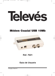
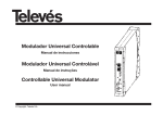
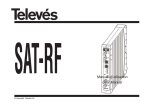
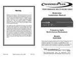
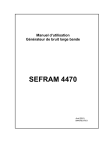
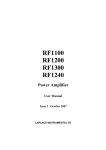
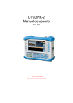
DTT
© Copyright, Televés S.A.
Procesador de Canales DTT
Manual de instrucciones
DTT Channels Processor
User manual
Procesador Canales DTT
INDICE
1.
Características técnicas . . . . . . . . . . . . . . . . . . . . . . . . . . . . . . . . . . . . . . . . . . . . . . . . . . . . . . . . . . . . . . . . . . . . . . . . . .
2.
Descripción de referencias . . . . . . . . . . . . . . . . . . . . . . . . . . . . . . . . . . . . . . . . . . . . . . . . . . . . . . . . . . . . . . . . . . . . . . . .
5
3.
Montaje . . . . . . . . . . . . . . . . . . . . . . . . . . . . . . . . . . . . . . . . . . . . . . . . . . . . . . . . . . . . . . . . . . . . . . . . . . . . . . . . . . . . . . .
6
3.1 Montaje en libro
6
.............................................................................
3.2 Montaje en Rack 19”
4.
5.
6.
Descripción de elementos
4
.........................................................................
7
........................................................................
8
4.1. Procesador Canales DTT . . . . . . . . . . . . . . . . . . . . . . . . . . . . . . . . . . . . . . . . . . . . . . . . . . . . . . . . . . . . . . . . . . . . . .
8
4.2. Fuente alimentación
.........................................................................
9
4.3. Central amplificadora
........................................................................
10
4.4. Programador PCT 3.0 . . . . . . . . . . . . . . . . . . . . . . . . . . . . . . . . . . . . . . . . . . . . . . . . . . . . . . . . . . . . . . . . . . . . . . . .
11
Instalación . . . . . . . . . . . . . . . . . . . . . . . . . . . . . . . . . . . . . . . . . . . . . . . . . . . . . . . . . . . . . . . . . . . . . . . . . . . . . . . . . . . . .
12
5.1. Consideraciones previas . . . . . . . . . . . . . . . . . . . . . . . . . . . . . . . . . . . . . . . . . . . . . . . . . . . . . . . . . . . . . . . . . . . . . .
12
5.2. Uso del programador externo . . . . . . . . . . . . . . . . . . . . . . . . . . . . . . . . . . . . . . . . . . . . . . . . . . . . . . . . . . . . . . . . . .
12
5.3. Recomendaciones para una instalación correcta . . . . . . . . . . . . . . . . . . . . . . . . . . . . . . . . . . . . . . . . . . . . . . . . . . .
14
Ejemplos de aplicación . . . . . . . . . . . . . . . . . . . . . . . . . . . . . . . . . . . . . . . . . . . . . . . . . . . . . . . . . . . . . . . . . . . . . . . . . . .
16
3
ESPAÑOL
Manual de instrucciones
Manual de instrucciones
Procesador Canales DTT
1.- CARACTERISTICAS TECNICAS
1.1.- Procesador canales DTT
Entrada
RF
refs. 5870, 5871
Margen de frecuencia de entrada: Ref. 5870: Un canal UHF (CCIR 8MHz, standards G,H,I,K,L).
Ref. 5871: Un canal BIII (CCIR 7MHz, standard B) oUHF (CCIR 7MHz, standard H)
Nivel de entrada:
-57 a -7 dBm (102 dBµV a 52 dBµV).
Margen variación frecuencia:
Ref. 5870: ±166.66 KHz; *Ref. 5871: ±125 KHz.
AGC:
Si.
Figura de ruido:
<20 dB.
Pérdida de retorno:
>10 dB.
Pérdida lado de entrada:
<1.5 dB
Impedancia:
75 ohm.
Conector:
“F” hembra.
Alimentación para previos:
+12V disponibles en el conector “UHF IN” .
Margen de frecuencia de salida:
Nivel de salida:
Ajuste nivel de salida:
Perdida de retorno:
Ganancia de pendiente:
Regulación de pendiente:
Nivel de espurios:
Impedancia:
END (Equivalent Noise Degrad.):
Conectores entrada/salida:
Ref. 5870: Un canal UHF (CCIR 8MHz, standards G,H,I,K,L).
Ref. 5871: Un canal BIII (CCIR 7MHz, standard B) o UHF (CCIR 7MHz, standard H).
Ref. 5870: ±166.66 KHz; Ref. 5871: ±125 KHz.
> 75 dBc/Hz @ 1KHz (cuando se usa como conversor de canales).
> 95 dBc/Hz @ 1KHz (cuando se usa como procesador).
85 dBµV ±5 dB.
> 15 dB.
> 12 dB.
< 2 dB.
±3 dB.
< -62 dBc
75 ohm.
< 1 dB.
“F” hembra.
Consumos:
+15V= 390 mA
Margen variación frecuencia:
Ruido de fase oscilador local:
Salida
RF
General
+5V= 220 mA
Las características técnicas descritas se definen para una temperatura ambiente máxima de 40°C
4
Manual de instrucciones
Procesador Canales DTT
Central
Rango de frecuencia:
Ganancia:
Margen de regulación:
Tensión de salida (60 dBc):
47 ... 860 MHz
45 ± 2 dB
20 dB
108 dBµV (6 canales DTT
@ 40 dB & Shoulder)
Conector:
Alimentación:
Consumo:
Toma de test:
“F” hembra
+ 15 V
750 mA @ 15V
-30 dB
Corrientes máximas
suministradas:
24V
18V
15V
5V
1 . 3.- Características técnicas Fuente Alimentación ref. 5029
Fuente
alimentación
Tensión de entrada:
Tensiones de salida:
230 ± 15 % V~
5V, 15V, 18V, 24V
(0,55 A)
(0,8 A)
(4,2 A)(1)
(6,6 A)
2.- DESCRIPCION DE REFERENCIAS
Ref. 5870 .... Procesador canales DTT UHF 8 MHz
Ref. 7234 .... Programador Universal
Ref. 5871 .... Procesador canales DTT UHF 7 MHz
Ref. 5071 .... Regleta soporte (10 mod. + Alimentación)
Ref. 5075 .... Central Amplif.
(47 - 860 MHz)
Ref. 5239 .... Regleta soporte (12 mod. + Alimentación)
Ref. 5029 .... F. Alimentación
(230 V ± 15 % - 50/60 Hz)
Ref. 5073 .... Carátula ciega
(24 V - 0,55 A)
(18 V - 0,8 A)
(15 V - 4,2 A)(1)
(5 V - 6,6 A)
Ref. 4061 .... Carga “F” 75 ohm
Ref. 5255 .... Interconexión T03/T05
Ref. 5072 .... Cofre universal
Ref. 5301 .... Subrack 19”
Ref. 5301
Ref. 5072
(1) Si utiliza las tensiones de 24V y/o 18V, deberá restar la potencia
consumida por éstas a la potencia de los 15V.
5
ESPAÑOL
1 . 2.- Características técnicas Central ref. 5075
Manual de instrucciones
Procesador Canales DTT
3 .- MONTAJE
3.1.- Montaje en libro
5870/5871
5075
CLAC!
5029
5071
5239
PWR
TEST
(-30dB)
4061
7234
PWR
PWR
1
2
5070
PC
T3
.0
B
UN
IVE
RS
AL
A
C
588
Re
f. 72
234 34
6
Manual de instrucciones
Procesador Canales DTT
ESPAÑOL
3.2.- Montaje en rack 19”
CLAC!
PWR
PWR
5301
PWR
TEST
(-30dB)
5073
7
Manual de instrucciones
Procesador Canales DTT
4. - DESCRIPCION DE ELEMENTOS
4.1.- Procesador Canales DTT
1.- Entrada RF +12V
2.- Entrada RF (lazo salida)
3.- Salida RF (lazo entrada)
4.- Salida RF
DIGITAL
1
5.- Conector programador
2
6.- Entrada alimentación módulo
PRGM
PWR
CTRL
3
7.- LED de estado
5
7
6
8.- Conector BUS de control
8
El procesador convierte el canal de entrada
DTT a la FI (36,15 MHz) y luego al canal de
salida que se desea. Incluye doble filtro SAW
para permitir procesar los canales digitales
con canales (digitales o analógicos) adyacentes, incluso si estos son analógicos con un
nivel de 35 dB más alto que el canal digital.
Los nuevos canales DTT se transmiten en
canales adyacentes a los servicios actuales
analógicos y así se impide el uso de amplifica-
Ch
Referencia producto
Indicar el canal de
salida programado
4
dores de canales convencionales debido a su
baja selectividad. Solamente pueden sostener
los canales adyacentes los procesadores de
canales con filtro SAW.
Los procesadores pueden ser usados como
conversores de canal (utilizando canales de
entrada y salida diferentes) o con el mismo
canal de entrada y salida.
El procesador de canal incluye una entrada y
una salida para la señal RF de entrada a través
8
DTT
470-862 MHz
5870
Ch
de los dos conectores superiores "F", así que
se puede alimentar varios procesadores con la
señal que se recibe.
También se puede alimentar un preamplificador (12 Vdc) a través del conector de entrada.
También tiene un conector de entrada y de
salida para la señal de salida RF con el objetivo de mezclar los canales antes de amplificación.
Manual de instrucciones
Procesador Canales DTT
ESPAÑOL
4.2.- Fuente de alimentación
(1)
PWR
+ 15V
+ 5V
+ 24V
GND
N/C
PWR
PWR
Conectores para
alimentar los
módulos (1)
LED encendido
NOTA:
La fuente de alimentación puede alimentar un máximo
de 8 procesadores, un amplificador 5075 y un previo.
Entrada RED
230V~
9
PWR
(1)
+ 18V
Manual de instrucciones
Procesador Canales DTT
4.3.- Central amplificadora
La unidad amplifica los canales
generados en los procesadores de
canales DTT, con un margen de frecuencias de 47 - 862 MHz.
Dispone de dos conectores de
señal de entrada para mezclar los
canales de dos sistemas. Si solamente se está usando una entrada,
se recomienda cargar la entrada no
utilizada con 75 ohm, ref. 4061.
1
2
TEST
(-30dB)
PWR
5
7
3
4
234632
1.- Salida RF
2.- Toma Test
3.- Entrada RF
4.- Entrada RF
5.- Entrada alimentación módulo
6.- Atenuador
7.- LED de estado
10
6
Hay un conector de salida y una
toma de test (-30 dB) en la parte
superior del panel frontal.
El amplificador necesita 15V de alimentación a través de un cable
plano de ocho hilos, el mismo tipo
de cable que se usa para alimentar
los otros módulos de este sistema.
Manual de instrucciones
Procesador Canales DTT
Se utiliza la unidad de programación para
seleccionar los canales de entrada y salida
(o frecuencias centrales), la frecuencia offset
(si se necesita), el nivel de salida, y la pendiente de la señal. Esta información es guardada dentro del procesador de canales
hasta que haya otro proceso de programación nuevo.
También indica el nivel de la señal de entrada, así informándonos si se necesita un preamplificador.
El programador consta de 4 teclas:
PCT 3.0
UNIVER
SAL
A
B
DT
T
58
C
70
Ch
: Tecla de cambio de menú de programación y grabación de datos.
: Tecla que permite la selección de un
dígito dentro de un determinado menú
de programación y realiza también el
cambio de menú normal a menú extendido.
: Tecla de incremento de dígito seleccionado.
: Tecla de decremento de dígito seleccionado.
Todas las funciones de programación se
realizan utilizando estas cuatro teclas.
La conexión entre el programador y el procesador de canal se puede realizar con el procesador encendido o apagado.
Siempre debe estar encendido antes de
empezar la programación.
11
ESPAÑOL
4. 4. - Programador ref. 7234
Manual de instrucciones
Procesador Canales DTT
Si se ha modificado algún parámetro, el
usuario debe guardar la nueva configuración. Para ello se pulsará la tecla
durante
5.1.- Antes de empezar
aproximadamente 3 segundos. La grabaComo ya se ha mencionado en el punto 4.2, ción correcta de los datos se denota con un
la fuente de alimentación puede alimentar parpadeo de los segmentos centrales de los
ocho procesadores, el amplificador y un pre- dígitos del programador:
amplificador.
5. - INSTALACIÓN
Para montar el sistema hay que sujetar los
módulos a un tubo metálico que está atornillado a la pared. Para conectar los módulos, Si se modifican los datos de configuración
véase la figura en sección 3.
pero no se graban, se recupera la configuración anterior transcurridos unos 30 segun5.2. - El programador externo
dos, es decir, se anulan los cambios realizaLos parámetros que se pueden medir y dos.
modificar con el programador son:
El programador se debe utilizar de la
siguiente forma:
Parámetros medidos
- Nivel de entrada
Parámetros que se pueden modificar
- Canal de entrada y canal de salida
Menú normal
1.- Insertar el programador en el conector
frontal de programación del módulo procesador. Aparecerá en primer lugar la versión
de software del producto. Por ejemplo la
versión 1.00:
2.- El siguiente menú (pulsando la tecla )
es el correspondiente al canal de salida. A
diferencia de lo que ocurre con el canal de
entrada, el diodo LED encendido en este
caso es el “C”. Los valores permitidos son
desde el canal 5 a 12 de la BIII.
El cambio de canal y la grabación de nuevos datos se realiza tal y como se ha explicado anteriormente.
- Alimentación para previo (12V)
- La dirección del procesador de canales
3.- Pulsando de nuevo la tecla
aparecerá
el ajuste del nivel de salida del procesador.
Esto es un índice entre 00 y 99. El índice 99
corresponde al máximo nivel de salida del
procesador que es aproximadamente 85
dBµV, mientras que el índice 00 representa
una atenuación de aproximadamente 20 dB
con respeto al valor máximo.
- Pendiente ganancia
- Offset de frecuencia de entrada y salida
12
El nivel de salida puede ser modificado con
las teclas y .
La grabación del nuevo valor de potencia se
efectuará tal y como se ha descrito al
comienzo de este apartado. De no procederse a la grabación del nuevo valor de
potencia, el equipo recuperará el valor anterior una vez transcurridos treinta segundos.
4.- Al insertar el programador en el conector
frontal del procesador aparecerá el primer
menú que es el número del canal de
entrada. En el caso de la ref. 5870, el
número de canal se corresponde con un
canal UHF (Estándares G, H, I, K y L) y será
un número que puede variar entre 21 y 69.
En el caso de la ref. 5871 el número de
canal se corresponde con la tabla de canales CCIR 7MHz (Australia) y será un número
entre 6 y 12 (BIII) o 28 y 69 (UHF). Aparece
también encendido el diodo LED verde. Por
ejemplo, en el caso de que el canal seleccionado fuese el 52, en el display aparecería
el siguiente contenido:
Procesador Canales DTT
dos de la tecla , tal y como se ha explicado anteriormente.
5.- El siguiente menú en aparecer (pulsando
la tecla ) es el correspondiente a la medida del nivel de entrada al módulo excitador. Se trata de una medida aproximada
que indica si el nivel de señal de entrada
está dentro del rango de funcionamiento
correcto del reemisor o si es excesivamente
bajo y por lo tanto es necesario el uso de un
preamplificador.
Si el nivel de entrada está dentro del rango
de funcionamiento correcto la lectura mostrada será de la forma:
En caso de que el nivel de entrada sea inferior a -57 dBm (52 dBµV) la lectura mostrada
será de la forma:
Menú extendido
Se accede a este menú pulsando la tecla
durante 2 segundos. La selección del menú
y el proceso de modificación y almacenaje
de datos se realiza de la misma forma que
en el menú normal.
Una vez dentro del Menú Extendido el programador regresa al Menú Normal de forma
automática después de haber efectuado
alguna modificación y grabación de alguno
de los parámetros. También se puede regresar al Menú Normal (en el caso de que no se
modifique ningún valor de parámetro) pulsando de nuevo la tecla
durante un par
de segundos.
1.- El primer menú extendido que aparece
es el correspondiente a la dirección del
procesador para control remoto mediante
el sistema de control de cabeceras de
Televés. Si, por ejemplo, la dirección asignada al reemisor fuese la 45, la lectura en el
display sería:
Los procesadores estarán conectados a un
bus común de control (marcado como CTRL
en el módulo excitador de cada reemisor) y
cada dispositivo deberá tener programada
El cambio de canal se realiza directamente
mediante las teclas y .
El cambio del canal de entrada se grabará
mediante la pulsación durante unos segun-
13
ESPAÑOL
Manual de instrucciones
Manual de instrucciones
una dirección única dentro del bus (entre 1 y
254), por lo que es responsabilidad del instalador el asegurarse de que no existen
direcciones duplicadas en este bus.
La dirección es un parámetro que se graba
cada vez que se modifica.
2.- Tensión input. El procesador permite
disponer a su conector de entrada de una
tensión de 12V para alimentar a un preamplificador para aquellos casos en que el
nivel de entrada sea inferior al mínimo
requerido.
La selección o no de la tensión se realiza
mediante las teclas y .
El display del programador mostrará 12ON
en el caso de que la tensión esté presente
en el conector de entrada y 12OF cuando
no lo esté:
3.- Pulsando de nuevo
se accede al
menú de variación de la pendiente.
Permite ajustar la planicidad del canal digital
en un rango de ±3 dB. Valores positivos de
pendiente indican que la curva de respuesta
del procesador es tal que la parte superior
(de más alta frecuencia) del canal está atenuada con respecto a la parte inferior, mien-
Procesador Canales DTT
tras que valores negativos indican que la
amplitud de la parte inferior es menor.
El formato del display para una pendiente
seleccionada de – 2dB sería:
Pulsando las teclas
y
se selecciona el
valor deseado de la pendiente en pasos de
1 dB.
4.- El siguiente Menú Extendido que aparece al pulsar esta tecla otra vez es el correspondiente al offset de la frecuencia de
entrada. Aparece también encendido el
LED “A”.
Mediante las teclas
y
se puede seleccionar un offset de +3, +2, +1, 0, -1, -2, -3,
los cuales se corresponden con los siguientes desplazamientos con respecto a la frecuencia:
OF-3
OF-2
OF-1
OF-0
OF+1
OF+2
OF+3
Ref 5870
-3 x 166 KHz
-2 x 166 KHz
-166 KHz
Frecuencia nominal
+166 KHz
+2 x 166 KHz
+3 x 166 KHz
14
OF-3
OF-2
OF-1
OF-0
OF+1
OF+2
OF+3
Ref 5871
- 3 x125 KHz
-2 x 125 KHz
-125 KHz
Frecuencia nominal
+125 KHz
+2 x 125 KHz
+3 x 125 KHz
La apariencia del display en caso de que el
valor seleccionado fuese OF-1 sería de la
forma:
La grabación del valor seleccionado se realiza de la misma manera que en el menú normal.
5.- Pulsando de nuevo
se accede al
menú de selección del offset de la frecuencia de salida. Se diferencia del offset de
entrada en que en este caso el LED encendido es el “C”. La selección y grabación del
offset seleccionado se realiza igual que en el
caso anterior.
Procesador Canales DTT
5.3.- Recomendaciones para la instalación de la cabecera
- Utilice un preamplificador si el nivel de
entrada al procesador de canales es bajo
(debajo de 57 dBµV). En caso contrario, la
C/N del canal digital será más bajo que 32
dB en la toma del usuario.
- El procesador de canal puede ser programado en modo conversor de canal (canales de entrada y salida diferentes) o en
modo amplificador de canal (mismo canal
de entrada/salida).
Si se usa como conversor de canal, el instalador es el responsable de asegurarse
que el nivel de la señal digital directa (o
parte de ella) que pasa a través de la
cabecera, y que afecta a los canales analógicos, es suficientemente bajo para que
el Set Top Box no se enganche a él. Es
tambien recomendable que la frecuencia
de salida del canal procesado sea más
baja que la frecuencia del canal directo
que llega al Set Top Box, dado que en el
caso de recibir la misma información en
dos frecuencias diferentes los receptores
se enganchan a la frecuencia más baja.
Frecuentemente los procesadores se usan
con el mismo canal de entrada y salida
(modo amplificador) para evitar problemas
de sintonización con el set-top box, recomendándose utilizar en dicho caso procesadores para los canales analógicos.
En ningún caso se usarán los procesadores
de canal como amplificadores para las
señales digitales junto con amplificación
banda ancha para los canales analógicos
(el STB podría “ver” los canales digitales
dos veces, primero cuando pasan a través
del amplificador de banda ancha y luego
otra vez cuando pasan a través del procesador de canales).
Si no pueden usarse procesadores de
canales para los canales analógicos, es
necesario al menos utilizar amplificadores
de canal de alta selectividad.
15
- Si está usando los procesadores de canal
como amplificadores, y el canal digital
procesado que está usando es el canal
adyacente superior a un canal analógico,
el canal digital necesita un offset según la
siguiente tabla:
- Para CCIR 8 MHz canales TV (UHF),
estándar B/G, offset de entrada y salida +1.
- Para CCIR 8 MHz canales TV (UHF),
estándar I, offset de entrada y salida
+3.
- Para CCIR 7 MHz canales de TV (BIII y
UHF), Australia, offset de entrada y
salida +3.
ESPAÑOL
Manual de instrucciones
Manual de instrucciones
Procesador Canales DTT
6.- EJEMPLOS DE APLICACION
Ejemplo 1.- Transmisor Mendip (UK)
Preamplificador
5 x Ref. 5098
Ref. 5028
6 x Ref. 5870
Ref. 5075
37
54
58
61
64
Canal entrada
Canal salida
A la distribución
Niveles de señal:
Canales analógicos: 120dBµV
Canales digitales: 108 dBµV
48
48
D6
52
52
D5
55
55
D2
59
59
D1
62
62
D3
65
65
D4
Niveles de señal:
D1, D2, D3, D4, D5, D6: 108dBµV
16
Procesador Canales DTT
ESPAÑOL
Manual de instrucciones
Ejemplo 2.- Transmisor Crystal Palace (UK)
Preamplificador
Amplificador Todabanda
3 x Ref. 5870
Ref. 5075
Niveles de señal:
Canal 5: 109dBµV
Rest of analog. ch.: 115dBµV
D2, D3, D4: 95dBµV
D1: 90dBµV
D5, D6: 85dBµV
RF Combiner
Canal entrada
Canal salida
Signal levels:
Channel 5: 108dBµV
Rest of analog. ch.: 114dBµV
D2, D3, D4: 94dBµV
D1, D5, D6: 100dBµV
34
34
D5
29
29
D6
25
25
D1
Niveles de señal:
D1: 110dBµV
D5, D6: 110dBµV
A la distribución
Network
17
Manual de instrucciones
Procesador Canales DTT
Example 3.- Sydney transmitter (Australia)
Preamplificador
5 x Ref. 5098
Ref. 5028
5 x Ref. 5871
Ref. 5075
2
7
9
10
28
Canal de entrada
Canal de salida
A la distribución
Network
Niveles de señal:
Canales analógicoss: 115dBµV
Canales digitales: 108 dBµV
6
6
8
8
11
11
12
12
Nivel de señal: 108dBµV
18
34
34
Manual de instrucciones
Procesador Canales DTT
ESPAÑOL
Example 4.- Sydney transmitter (Australia)
Procesadores para canales analógicos
Procesadores para
canales digitales
Preamplificadores
4 x Ref. 5871
Ref. 5096
5 x Ref. 5871
Ref. 5075
A la distribución
Network
Ref. 5028
Nivel de señales:
Canales análogos: 110dBµV
Canales digitales: 104 dBµV
Canal de entrada
Canal de salida
2
2
7
7
9
9
10
10
28
28
Canal de entrada
Canal de salida
19
6
6
8
8
11
11
12
12
34
34
User manual
DTT Channels Processor
INDEX
1.
Technical specifications . . . . . . . . . . . . . . . . . . . . . . . . . . . . . . . . . . . . . . . . . . . . . . . . . . . . . . . . . . . . . . . . . . . . . . . . . .
2.
System composition . . . . . . . . . . . . . . . . . . . . . . . . . . . . . . . . . . . . . . . . . . . . . . . . . . . . . . . . . . . . . . . . . . . . . . . . . . . . .
22
3.
Mounting . . . . . . . . . . . . . . . . . . . . . . . . . . . . . . . . . . . . . . . . . . . . . . . . . . . . . . . . . . . . . . . . . . . . . . . . . . . . . . . . . . . . . .
23
3.1. Wall mounting . . . . . . . . . . . . . . . . . . . . . . . . . . . . . . . . . . . . . . . . . . . . . . . . . . . . . . . . . . . . . . . . . . . . . . . . . . . . . .
23
3.2. 19” rack mounting . . . . . . . . . . . . . . . . . . . . . . . . . . . . . . . . . . . . . . . . . . . . . . . . . . . . . . . . . . . . . . . . . . . . . . . . . . .
24
4.
5.
6.
21
Identification and use of the system elements . . . . . . . . . . . . . . . . . . . . . . . . . . . . . . . . . . . . . . . . . . . . . . . . . . . . . . . . .
25
4.1. DTT channel processor . . . . . . . . . . . . . . . . . . . . . . . . . . . . . . . . . . . . . . . . . . . . . . . . . . . . . . . . . . . . . . . . . . . . . . .
25
4.2. Power supply unit . . . . . . . . . . . . . . . . . . . . . . . . . . . . . . . . . . . . . . . . . . . . . . . . . . . . . . . . . . . . . . . . . . . . . . . . . . .
26
4.3. Amplifier
27
..................................................................................
4.4. The programming unit ref. 7234 . . . . . . . . . . . . . . . . . . . . . . . . . . . . . . . . . . . . . . . . . . . . . . . . . . . . . . . . . . . . . . . .
28
Installation . . . . . . . . . . . . . . . . . . . . . . . . . . . . . . . . . . . . . . . . . . . . . . . . . . . . . . . . . . . . . . . . . . . . . . . . . . . . . . . . . . . . .
29
5.1. Previous considerations . . . . . . . . . . . . . . . . . . . . . . . . . . . . . . . . . . . . . . . . . . . . . . . . . . . . . . . . . . . . . . . . . . . . . .
29
5.2. How to use the external programmer . . . . . . . . . . . . . . . . . . . . . . . . . . . . . . . . . . . . . . . . . . . . . . . . . . . . . . . . . . . .
29
5.3. Setting-up recommendations for a correct headend installation . . . . . . . . . . . . . . . . . . . . . . . . . . . . . . . . . . . . . . . .
32
Typical application
33
..............................................................................
20
User manual
DTT Channels Processor
1.- TECHNICAL SPECIFICATIONS
1.1.- DTT
refs. 5870, 5871
RF
input
Ref. 5870: One UHF Channel (CCIR 8MHz, standars G, H, I, K, L).
Ref. 5871: One BIII channel (CCIR 7MHz, standard B) or UHF (CCIR 7MHz, standard H).
Input signal level:
-57 to -7 dBm (102 dBµV a 52 dBµV).
Frequency offset availability:
Ref 5870: ± 166.66KHz; *Ref 5871: ± 125 KHz.
AGC:
Yes.
Noise figure:
< 20 dB.
Return losses:
> 10 dB.
Input loop through losses:
<1.5 dB.
Impedance:
75 ohm.
Connector:
"F" female.
Preamplifier power sup. availab.: +12V at "UHF IN" connector .
Frequency range:
Output level:
Output level adjustable level:
Return losses:
Gain slope:
Slope regulation:
Spurious level:
Impedance:
END (Equivalent Noise Degrad.):
Connector:
Ref 5870: One UHF Channel (CCIR 8MHz, standares G, H, I, K, L)
Ref 5871: One BIII channel (CCIR 7MHz, standard B) or UHF (CCIR 7 MHz, standard H).
Ref 5870: ± 166.66KHz; Ref 5871: ± 125 KHz;
>75 dBc/Hz @ 1KHz when used as channel converter.
> 95 dBc/Hz @ 1KHz when used as an amplifier (same input and output channels).
85 dBµV ± 5 dB.
>15dB.
> 12 dB.
< 2dB.
± 3 dB.
<-62dBc as regards the nominal output level.
75 ohm.
< 1dB.
"F" female.
Power consumption:
+15V: 390 mA; +5V: 220 mA.
Frequency offset availability:
Local Oscillator phase noise:
RF
output
General
The technical specifications are defined with a maximum room temperature of 40º C.
21
ENGLISH
Frequency range:
User manual
DTT Channels Processor
1 . 2.- Amplifier technical specifications ref. 5075
Amplifier
Frequency range:
Gain:
Regulation margin:
Output level:
47 ... 860 MHz
45 ± 2 dB
20 dB
108 dBµV (6 DTT channels
@37 dB shoulder)
Input/Output connector:
DC supply:
Power comsumption:
Test connector atten.:
230 ± 15 % V~
5V, 15V, 18V, 24V
Maximum currents:
"F" female
+15 V
750 mA @15V
30 dB
1 . 3.- Power supply unit ref. 5029
Power
supply
Mains voltage:
Output voltages:
24V
18V
15V
5V
(0.55 A)
(0.8 A)
(4.2 A)(1)
(6.6 A)
2.- SYSTEM COMPOSITION
Ref. 5870 .... 8 MHz UHF DTT channel processor
Ref. 7234 .... Portable Universal Programming Unit
Ref. 5871 .... 7 Mhz Band III and UHF channel processor
Ref. 5071 .... Wall Support (10 mod. + PSU)
Ref. 5075 .... Hybrid Amplifier
(47 - 860 MHz)
Ref. 5239 .... Wall Support (12 mod. + PSU)
Ref. 5029 .... Power Supply Unit
(230 V ± 15 % - 50/60 Hz)
(24 V - 0.55 A)
(18 V - 0.8 A)
(15 V - 4.2 A)(1)
(5 V - 6.6 A)
Ref. 5073 .... Blank plate
Ref. 4061 .... 75 ohm adapter load “F”
Ref. 5255 .... T03/T05 link cable
Ref. 5072 .... Modular cabinet
Ref. 5301 .... Sub-rack 19"
Ref. 5301
Ref. 5072
(1) When the voltages 24V and/or 18V are being used, it is necessary to
take the power of these voltages away from 15V power.
22
User manual
DTT Channel Processor
3 .- MOUNTING
3.1.- Wall mounting
5870/5871
5075
CLAC!
5029
5071
5239
TEST
(-30dB)
7234
2
5070
PC
T3
.0
B
UN
IVE
RS
AL
A
C
588
Re
f. 72
234 34
23
ENGLISH
4061
PWR
PWR
PWR
1
User manual
DTT Channels Processor
3.2.- 19” rack mounting
CLAC!
PWR
PWR
5301
PWR
TEST
(-30dB)
5073
24
User manual
DTT Channel Processor
4. - IDENTIFICATION AND USE OF THE SYSTEM ELEMENTS
4.1.-DTT Channel Processor. Front and side views
1.- RF Input plus 12V
2.- RF Output (input loop-through)
3.- RF Input (output loop-through)
4.- RF Output
5.- Programmer socket
6.- Powering input
7.- LED on
8.- Control BUS connector
DIGITAL
1
2
CTRL
PWR
PRGM
5
6
Ch
4
The Processor converts the input DTT channel down to the Intermediate Frequency (36,15
MHz) and then back to desired output channel. It includes double SAW filtering to allow
the processing of digital channels having adjacent (analogue or digital) channels, even if the
latter are analogue with a level 35 dB higher
than that of the digital.
The new DTT channels are transmitted in
channels adjacent to the current analogue ser-
DTT
470-862 MHz
8
Product reference
Indicate the programmed
output channel
vices thus impeding the use of the conventional Channel Amplifiers due to their low selectivity. Only channel processors including SAW
filtering are able to cope with adjacent channels.
The Processors may be used as channel converters (using different input and output channels) or with the same input and output channel.
The Channel Processor includes one input and
25
5870
Ch
one output for the RF input signal through the
two upper "F" connectors, so it is possible to
power several processors with the incoming
signal.
It also allows the powering of a preamplifier (12
Vdc) through the input connector.
It also has one input and one output connectors for the RF output signal with the aim of
mixing the processed channels before the
amplification.
ENGLISH
3
7
User manual
DTT Channel Processor
4.2.- Power Supply Unit
(1)
+ 18V
PWR
+ 5V
+ 24V
GND
N/C
PWR
PWR
Power outputs (1)
Power ON LED
NOTE:
The power supply unit can power a maximum
of 8 DTT channel processors and amplifiers.
Mains
230V~
26
PWR
(1)
+ 15V
User manual
DTT Channel Processor
4.3.- Amplifier
The amplifier carries out the amplification of the generated channels in the
DTT channel processors, covering a frequency range of 47 - 862 MHz. It disposes of two input signal connectors for
the mixing of channels coming from two
systems. If only one of the inputs is
used, it is advisable to load the unused
input with 75 ohm, ref. 4061.
1
2
TEST
(-30dB)
PWR
5
7
3
4
234632
6
The amplifier disposes of an output
connector and a Test socket (-30dB)
located at the top of the front panel.
The amplifier is powered with 15V via an
eight-wire flat cable, the same type as
that used for powering the other modules of the system.
1.- RF Output
ENGLISH
2.- Test socket
3.- RF Input
4.- RF Input
5.- Powering input
6.- Attenuator
7.- LED on
27
User manual
DTT Channel Processor
4. 4. - The programming unit ref. 7234
By means of the programming unit, the
input and output channels (or central frequencies), the frequency offset (if required),
the output level and the slope of the signal
and the are selected. This information is
recorded into the channel processor until a
new programming procedure takes place.
It also provides an indication of the input
signal level, there indicating whether it is
below the level for which a preamplifier
would be required.
The programmer consists of four buttons:
: The button that changes the programming menu and recording information.
: The button that allows the selection of a
digit within a specified programming
menu. It also carries out the change from
the normal menu to an extended menu.
: The button for increasing the value of
the selected digit.
: The button for decreasing the value of
the selected digit.
Using these four buttons, all the programming functions are carried out.
The connection between the programmer
and the channel processor can be made with
the processor switched either ON or OFF.
It must always be switched ON before
starting the programming procedure.
PCT 3.0
UNIVER
SAL
A
B
DT
T
58
C
70
Ch
28
User manual
5. - INSTALLATION
5.1.- Previous considerations
As already mentioned in the point 4.2, the
power supply unit can feed 8 processors,
the amplifier and one preamplifier.
Mounting the system consists of fixing the
modules to a metallic rail bolted onto the
wall. The way of connecting all the modules
is described in the section 3 figure.
5.2.- How to use the external programmer
The parameters that can be measured and
modified with the programmer are:
Measured parameters
DTT Channel Processor
If any of the equipment's parameters are
modified, it is necessary to save the new
configuration. To do this, the user must
press the
button for approximately 3
seconds. If the data is correctly saved, the
central segments of the programmer's digits
will flash:
Normal menu
If the configuration data is modified but not
saved, the previous configuration is retrieved after about 30 seconds, in other words,
any changes made are cancelled.
2.- The following menu (pressing the
button) is the Output Channel Menu. Unlike
what happens with the input channel, in this
case the “C” LED lights up.
The range of permitted values is the same
for the input channel menu.
A change in the channel and the consequent
saving of new data is carried out as explained above.
The programmer must be used in the following way:
- Input level
Parameters that can be modified
1.- Insert the programmer in the front connector of the programming module
(“PRGM”). First, the version of the software in use, will appear. For example 1.00:
- Input channel and output channel
3.- By pressing the
button again, the
adjustment of the output level of the processor will appear. This is an index between 00
and 99. The index 99 corresponds to the
maximum output level of the processor, which
is in the order of 85 dBµV, while the index 00
represents an attenuation of approximately 20
dB as regards the maximum value.
The output level can be modified with the
& buttons.
- Channel processor´s address
- Gain slope
- Input and output frequency offset
29
ENGLISH
- Powering for preamplifier (12V)
User manual
To save the new value for the output level,
follow the explanation provided at the start
of the instructions. If the new value is not
saved, the equipment will automatically
retrieve the previous value once thirty
seconds have passed.
4.- When the programmer is inserted into
the connector on the front of the processor,
the first menu will appear. This is the input
channel number. In case of reference 5870
the channel number corresponds to an UHF
Channel (CCIR 8MHz, standars G, H, I, K, L),
and can vary from 21 to 69. In case of reference 5871 the channel number corresponds to the CCIR 7MHz channel table
(Australia) and it can be any number from 6
to 12 (BIII) or 28 to 69 (UHF). The green LED
will also light up. For example, if the selected channel were number 52, the display
would appear like this:
DTT Channel Processor
5.- The following menu that appears (by
pressing the
button) corresponds to the
measurement of the input level to the exciter. This is an approximate reading that indicates if the level of the input signal is within
the correct working range of the relay transmitter or if it too low (thereby indicating the
need for a preamplifier).
If the input level is within the correct working
range, the display will read:
If the input level is lower than -57 dBm (52
dBµV) the display will read:
Extended menu
It can be accessed by pressing the
button for 2 seconds. The menu selection and
the process of changing and saving the data
is carried out in the same way as in the
Normal Menu.
Once in the Extended Menu, the programmer will return to the Normal Menu automatically after there has been a modification
and subsequent saving of any of the parameters. You can also return to the Normal
Menu (when nothing has been changed) by
pressing the
button again for a couple of
seconds.
1.- The first Extended Menu that appears
corresponds to the processor's address
for remote control via Televés' headend
control system. For example, if the address
assigned to the relay transmitter is 45, the
display will read:
A change of channels can be carried out
directly using the & buttons.
A change in the input channel can be saved
by pressing the
button for a few seconds,
as explained earlier.
The processors are connected to a common
control bus (marked CTRL in the exciter of
each relay transmitter) and each device
must have a unique address in the bus (between 1 and 254). Therefore it is the installer's responsibility to make sure that none
30
DTT Channel Processor
of the addresses are repeated on this bus.
The address is a parameter that is saved
every time it is modified.
The format of the display for a selected
slope of - 2dB would be:
2.- Preamplifier powering. The processor
disposes of 12V that passes through the
input connector to power a preamplifier for
those cases in which the input level is less
than the minimum required.
To select this powering, the user must use
the & buttons.
The programmer's display will read 12ON if
the power is in the input connector and
12OF when it is not:
By pressing the
&
buttons, the user
can select the desired slope in steps of 1
dB.
3.- By pressing the
button again, the user
gains access to the menu that deals with the
slope variation.
This lets you adjust the flatness of the digital
channel by up to ± 3 dB. If the slope values
are positive, then this indicates that the processor's response curve (with the highest
frequency) is such that the top part (with the
highest frequency) of the channel is attenuated with regard to the lower part, while
negative values indicate that the amplitude
of the lower part is lower.
4.- Press the key again to select the next
menu for the input frequency offset. In this
mode also the A LED will be ON.
Pressing the & keys an offset value between
+3, +2, +1, 0, -1, -2, -3 can be selected.
Each one represents a frequecy shifting
according with the following tables:
OF-3
OF-2
OF-1
OF-0
OF+1
OF+2
OF+3
Ref 5870
-3 x 166 KHz
-2 x 166 KHz
-166 KHz
Nominal Frequency
+166 KHz
+2 x 166 KHz
+3 x 166 KHz
31
OF-3
OF-2
OF-1
OF-0
OF+1
OF+2
OF+3
Ref 5871
- 3 x125 KHz
-2 x 125 KHz
-125 KHz
Nominal frequency
+125 KHz
+2 x 125 KHz
+3 x 125 KHz
For an offset value -1, the display will show
the following:
Record data as done in the normal menu.
5.- Press the
key again to select the output frequency offset. In this mode the “C”
LED will be ON.
Follow the previously explained procedure
for selecting, changing and recording the
data.
ENGLISH
User manual
User manual
DTT Channel Processor
5.3.- Setting-up recommendations for a
correct headend installation.
- Use a preamplifier if the input level to the
channel processors is low (below 57
dBµV). Otherwise the C/N of the digital
channel at the user´s outlet will be lower
than 32 dB.
- The Channel Processors can be programmed either in channel converter mode (different input and output channel) or in
channel amplifier mode (same input/output
channel).
If they are used as channel converters the
installer must make sure that the level of
the digital signal (or part of it) passing
through the part of the headend handling
the analogue channels is low enough as to
not make the Set Top Box to lock it. The
output channel frequency should be lower
than that at the channel converter input.
It is quite likely that the processors are
commonly used with the same input and
output channel to avoid tuning problems
with the set-top box.
When used as amplifiers (same input and
output channel) it is highly recommended
to use processors for the analogue channels as well. Processors for the analogue
channels must be the same as those for
digitals (ref. 5870 or 5871)
In any case, it will not be possible to use
channel processors as amplifiers for the
digital signals and broadband amplifiers for
the analogue channels (the STB would
"see" the digital cahnnels twice, the one
passing through the broadband amplifier
and the same channel passing through the
channel processor).
If it is not possible to use channel processors for the analogue channels, use at
least high selectivity channel amplifiers.
- If channel processors are used as amplfiers, and the processed digital channel us
upper adjacent to an analogue one, an offset must be selected for the digital channel
according to the next table:
- For CCIR 8 MHz (UHF) TV channels,
standard B/G, set both input and output
offset to +1.
- For CCIR 8 MHz (UHF) TV channels,
standard I, set both input and output
offset to +3.
- For CCIR 7MHz (BIII and UHF) TV channels, Australia, set both input and output
offset to +3.
32
User manual
DTT Channel Processor
6.- TYPICAL APPLICATION
Example 1.- Mendip transmitter (UK)
Preamplifier
5 x Ref. 5098
Ref. 5028
6 x Ref. 5870
Ref. 5075
54
58
61
64
Input channel
Output channel
To the distribution
Network
Signal levels:
Analogue channels: 120dBµV
Digital channels: 108 dBµV
48
48
D6
52
52
D5
55
55
D2
59
59
D1
62
62
D3
65
65
D4
Signal levels:
D1, D2, D3, D4, D5, D6: 108dBµV
NOTE: The digital channels could be converted since they are located
in the upper part of the UHF spectrum.
33
ENGLISH
37
User manual
DTT Channel Processor
Example 2.- Crystal Palace transmitter (UK)
Preamplifier
Broadband amplifier
3 x Ref. 5870
Ref. 5075
Signal levels:
Channel 5: 109dBµV
Rest of analog. ch.: 115dBµV
D2, D3, D4: 95dBµV
D1: 90dBµV
D5, D6: 85dBµV
RF Combiner
Input channel
Output channel
Signal levels:
Channel 5: 108dBµV
Rest of analog. ch.: 114dBµV
D2, D3, D4: 94dBµV
D1, D5, D6: 100dBµV
34
34
D5
29
29
D6
25
25
D1
Signal levels:
D1: 110dBµV
D5, D6: 110dBµV
To the distribution
Network
34
User manual
DTT Channel Processor
Example 3.- Sydney transmitter (Australia)
Preamplifier
5 x Ref. 5098
Ref. 5028
5 x Ref. 5871
Ref. 5075
7
9
10
28
Input channel
Output channel
To the distribution
Network
Signal levels:
Analogue channels: 115dBµV
Digital channels: 108 dBµV
6
6
8
8
11
11
12
12
34
34
Signal levels: 108dBµV
NOTE: The digital channels could be converted since they are located
in the upper part of the UHF spectrum.
35
ENGLISH
2
User manual
DTT Channel Processor
Example 4.- Sydney transmitter (Australia)
Processors for analogue channels
Processors for
digital channels
Preamplifier
4 x Ref. 5871
Ref. 5096
5 x Ref. 5871
Ref. 5075
To the distribution
Network
Ref. 5028
Signal levels:
Analogue channels: 110dBµV
Digital channels: 104 dBµV
Input channel
Output channel
2
2
7
7
9
9
10
10
28
28
Input channel
Output channel
6
6
8
8
11
11
12
12
34
34
NOTE: In this configuration, processors can be used as converters in order to reallocate the channels.
In the installation of the figure, input and output offset for channels 8 and 11 (digital) processor, must be set at +3.
36
DTT
A.- TABLA DE CANALES / CHANNELS TABLE
C / CH
6
7
8
9
10
11
12
21
22
23
24
25
26
27
28
29
30
31
32
33
34
35
36
37
38
39
40
41
42
43
44
45
46
47
48
Ref. 5870
CCIRR
471.25
479.25
487.25
495.25
503.25
511.25
519.25
527.25
535.25
543.25
551.25
559.25
567.25
575.25
583.25
591.25
599.25
607.25
615.25
623.25
631.25
639.25
647.25
655.25
663.25
671.25
679.25
687.25
Ref. 5871
Australia
175.25
182.25
189.25
196.25
210.25
217.25
224.25
203.25 (9 A)
527.25
534.25
541.25
548.25
555.25
562.25
569.25
576.25
583.25
590.25
597.25
604.25
611.25
618.25
625.25
632.25
639.25
646.25
653.25
660.25
667.25
C / CH
49
50
51
52
53
54
55
56
57
58
59
60
61
62
63
64
65
66
67
68
69
Ref. 5870
CCIRR
695.25
703.25
711.25
719.25
727.25
735.25
743.25
751.25
759.25
767.25
775.25
783.25
791.25
799.25
807.25
815.25
823.25
831.25
839.25
847.25
855.25
37
Ref. 5871
Australia
674.25
681.25
688.25
695.25
702.25
709.25
716.25
723.25
730.25
737.25
744.25
751.25
758.25
765.25
772.25
779.25
786.25
793.25
800.25
807.25
814.25
DTT
39
SUCURSALES
GIJON
A CORUÑA
BILBAO
CANTABRIA
LUGO
SANTIAGO
VIGO
GUIPUZCOA
ALAVA
OURENSE
LEON
ZAMORA N
PALENCIA
NAVARRA
BARCELONA
SORIA
ZARAGOZA
ZAMORA
SEGOVIA
SALAMANCA
GUADALAJARA
AVILA
OPORTO
CACERES
TOLEDO
CASTELLON
CUENCA
CIUDAD REAL
VALENCIA
ALICANTE
JAEN
PALMA DE
MALLORCA
ALBACETE
BADAJOZ
CORDOBA
TARRAGONA
TERUEL
MADRID
LISBOA
GIRONA
HUESCA
BURGOS
LA RIOJA
VALLADOLID
MURCIA
BALEARES
BARCELONA C.P. 08940
C/ Sant Ferrán, 27
Cornellá - Barcelona
Telfs. 93 377 08 62 / 93 474 29 50
Fax
93 474 50 06
E-mail [email protected]
BILBAO C.P. 48150
Iberre kalea, módulo 16,
pabellón 15-B
Sangroniz-Sondika
Tfnos. 94 471 12 02 / 94 471 24 78
Fax
94 471 14 93
[email protected]
GRANADA
HUELVA
SEVILLA
ALMERIA
MALAGA
CADIZ
CANARIAS
SUCURSALES
TENERIFE
LAS PALMAS C.P. 35006
Gral. Mas de Gaminde 26.
Tfnos. 928 23 11 22 / 928 23 12 42
Fax
928 23 13 66
[email protected]
MADRID C.P. 28005
Paseo de los Pontones 11.
Tfnos. 91 474 52 21 / 91 474 52 22
Fax
91 474 54 21
[email protected]
MURCIA C.P. 30010
Polígono Conver
C/ Rio Pliego 22
Tfnos. 968 26 31 44 / 968 26 31 77
Fax
968 25 25 76
[email protected]
SEVILLA C.P. 41008
Pol. Ind. Store - C/ A-6. Nave 5
Tfnos. 95 443 64 50 / 95 443 58 00
Fax
95 443 96 93
[email protected]
VALENCIA C.P. 46020
Plaza Jordi San Jordi s/n
Tfnos. 96 337 12 01 / 96 337 12 72
Fax
96 337 06 98
[email protected]
VIGO C.P. 36204
Escultor Gregorio Fernández, 5
Tfnos. 986 42 33 87 / 986 42 40 44
Fax
986 42 37 94
[email protected]
TENERIFE C.P. 38108
Avda. El Paso, 25
Los Majuelos - La Laguna.
Tfnos. 922 31 13 14 / 922 31 13 16
Fax
922 31 13 33
[email protected]
DELEGACIONES
CEUTA
LAS PALMAS
A CORUÑA C.P. 15011
Gregorio Hernández 8.
Tfnos. 981 27 47 31 / 981 27 22 10
Fax
981 27 16 11
[email protected]
GIJON C.P. 33210
C/Japón, 14
Tfnos : 985 15 25 50 / 985 15 29 67
Fax : 985 14 63 89
[email protected]
MELILLA
FABRICAS
DELEGACIONES
ALMERIA C.P. 04008
Campogrís 9.
Tfno. 950 23 14 43
Fax
950 23 14 43
[email protected]
BURGOS C.P.09188
C/Real, s/n,
San Adrián de Juarros
Tfno. 947 56 04 58 / 670 73 75 86
CACERES/ BADAJOZ
C.P. 06010
C/Jacobo Rodríguez
Pereira, nº11-Oficina
Tfno. 924 20 74 83 / 670 70 21 93
Fax.
924 20 01 15
[email protected]
Rúa B. de Conxo, 17 - 15706 SANTIAGO DE COMPOSTELA
Tel. 981 52 22 00 Fax 981 52 22 62
GIRONA C.P. 17190 (Salt)
Ramón Sambola. 9º Ent. 1ª.
Tfno. 972 23 25 43 / 607 23 88 40
[email protected]
GRANADA
Tfno. 958 13 78 29
Móvil: 609 62 70 96
[email protected]
JAEN C.P. 23007
Hermanos Pinzón, 8-bajo
Tfnos. 953 29 50 40 / 953 29 52 21
639 98 44 89
Fax
953 29 52 10
[email protected]
LA RIOJA C.P. 26004
San Prudencio 19. bajo
Tfno. 941 23 35 24
Fax
941 25 50 78
[email protected]
MALAGA C.P.29004
Pol. Santa Barbara - C/ Fidias 13.
Tfno. 95 223 98 81
Fax
95 217 37 30
[email protected]
P. DE MALLORCA C.P. 07007
Ferrer de Pallares 45. bajo D.
Tfno. 971 24 70 02
Fax
971 24 53 42
[email protected]
MELILLA C.P.52006
Paseo Marítimo Mir Berlanga, 17
Edif. Antares, C, 4ºB
Tfno. 600 45 35 13
Fax
600 43 35 14
[email protected]
SALAMANCA
ZAMORA
VALLADOLID C.P. 47008
C/ Arrecife 12.
Tfno. 983 22 36 66
Fax
983 22 36 66
[email protected]
NAVARRA C.P. (Pamplona) 31007
Avda. Sancho el Fuerte 9.
Tfno. 948 27 35 10
Fax
948 17 41 49
[email protected]
HUESCA
ZARAGOZA C.P. 50002
C/ Monasterio de Alahón 1-3.
Tfno. 976 41 12 73
Fax
976 59 86 86
[email protected]
[email protected]
www.televes.com
TELEVES ELECTRONICA PORTUGUESA
MAIA - OPORTO
Via . Dr Francisco Sa Carneiro. Lote 17.
ZONA Ind. MAIA 1. Sector-X MAIA.
C.P. 4470 BARCA
Tel.
351 22 9418313
Fax
351 22 9488719 / 9416180
[email protected]
LISBOA
C.P. 1000 Rua Augusto Gil 21-A.
Tel.
351 21 7932537
Fax
351 21 7932418
[email protected]
TELEVES UNITED KINGDOM LTD
Unit 11 Hill Street, Industrial State
CWMBRAN, GWENT NP44 7PG. (United Kingdom)
Tel.
44 01 633 87 58 21
Fax
44 01 633 86 63 11
[email protected]
TELEVES FRANCE S.A.R.L.
35 Av St Germain des Noyers
77400 St Thibault des Vignes (France)
Tel. 01 60 35 92 10
Fax 01 60 35 90 40
[email protected]
TELEVES MIDDLE EAST FZE
P.O. Box 17199
JEBEL ALI FREE ZONE DUBAI,
UNITED ARAB EMIRATES
Tel.
9714 88 343 44
Fax. 9714 88 346 44
[email protected]
103413/4 - 04-01