1
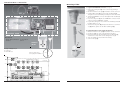
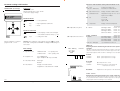
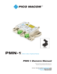
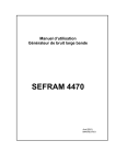
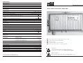
Specifications Optical parameters Wavelength Optical return loss Fiber Optical connector 1290nm - 1600nm > 40 dB single mode 9 / 125 µm E2000 / APC CATV parameters Output impedance Output return loss Frequency range Controlled output level ALC (OMI=5%) CNR for 42 Ch. CENELEC, opt. link=6dB Distorsion products for CENELEC 42 Ch @ 85 dBµV 4 dB slope CTB CSO Optical input level for controlled electrical output level Amplitude response (O-E) Sensitivity RF connector SAT IF parameters Output impedance Output return loss Frequency range Controlled output level ALC (OMI=5%) Optical input level for controlled electrical output level Amplitude response (O-E) Sensitivity CNR for 40 Ch. CENELEC, opt. link=6dB RF connector NMS functions Monitoring Configuration Alarms Optical input level Attenuator settings ALC mode CATV ALC mode SAT IF Attenuation CATV (manual mode) Attenuation SAT IF (manual mode) Optical input power too high / low General data Supply voltage Power consumption Power consumption with LT..+ Transponder. Protection class Dimensions B x W x D Max. humidity not condensing Ambient temperature Storage temperature Operating instructions LR 60 Optical Transceiver "Mininode" 75 Ω ≥ 18 dB (-1,5 dB / oct.) 45 - 862 MHz 85 dBµV @ 862MHz 4 dB slope > 48 dB > 68 dB > 65 dB -5dBm...+3 dBm < ± 1 dB ≤ 15 pA /√ Hz F 75 Ω ≥ 12 dB 950 - 2200 MHz 85 dBµV @ 2200 MHz 4 dB slope -5dBm...+3 dBm < ± 1,5 dB ≤ 20 pA /√ Hz > 26 dB* > 36 dB** F auto/manual auto/manual 0 - 20 dB 0 - 20 dB All alarm thresholds are variable 180-265 VAC 6W < 10 W II / IP 54 244 x 134 x 84 mm 95 % -10°C ...+50°C -25°C...+75°C Compact optical receiver for CATV and SAT IF over one fiber All settings / pollings by WISI Handset OK 41 Integrated splice box Two separate outputs for SAT IF and CATV Automatic level control (ALC) for constant output level EN 50 083-1ff Services and repairs should only be carried out by experts. Pay attention to live parts or wires! Switch off power supply. * measured with LT 61 in dual band operation ** measured with LT 61 in single band operation 07/03 LASER CLASS 1 Do not kink the optical fibre. Minimum bending radius 1.5 cm. 043 230 Transceiver LR 60 + Accessories Mounting of fiber LT 19/20 /21 a. Pigtail with E2000 APC connector (see Fig. 3) 1. Remove the locking lever (3) of the connector by pushing it out upwards. 2. Unscrew and remove the cap (5) and slide it over the connector. 3. Pull the rubber gasket (2) out of the fiber feedthrough (1). This gasket is not needed during assembly and can be discarded. 4. Thread the E2000 APC connector through the fiber feedthrough (1) into the LR 60. 5. Press the locking lever (3) into the E2000 APC connector and slide the connector into the E2000 APC coupling. 6. Lay the fiber, taking care not to kink it. The minimum permissible bending radius is 1.5 cm. 7. Slit the enclosed gasket (4) and press the fiber into it. Screw the cap (5) with its gasket onto the fiber feedthrough (1). (1) (2) JP 1,2 RJ 45 b. 1. 2. 3. Pigtails with mono mode (single mode) fiber Unscrew and remove the cap (5) and slide it over the end of the fiber. Cut about 50-60 cm of the outer sheath from the fiber. Before threading the fiber through the fiber feedthrough (1), ensure that no components can be damaged (see fig. 4). 4. Splice the pigtail. Do not bend the fiber sharply. 5. Screw on the cap (5). (3) Transceiver LR 60 Accessories - Return path transmitter - Handset LEDs LT 19 / 20 / 21 OK 41 Slit Handset OK 41 (4) Factory settings: JP1, 2 LT 19 FP-Laser LT 20/21 DFB-Laser (5) Remove jumper JP1,2 before plug-in LT 19/20/21 JP 1,2 Fig 3 230V 12V 5V -8V Mini Node LR 60 / LT 19, 20, 21 950 - 2200 MHz SAT OUT Opt. in Handsetinterface µ Controller, ADC 47(85) - 862 MHz LD Control LT 19, 20, 21 LMT Interface HMS Transp.Interf. CATV OUT Jumper Opt. out JP 4 fg= 15 MHz nc 15 - 65 MHz Parameter settings with handset Handset OK... (accessory) L R20 V 00 . 9 7 0 6 Functions with installed return-path transmitter LT 20... Connection Unscrew the cover. Plug the handset into socket "RJ-45". Connect the supply voltage. 4a. Laser LT 20.../21...-LED flashes Activated - module active Deactivated - module inactive 4b. Opt. Transm. Power Display: should be +3dBm / 2mW 4c. Modulation index Adjustable in range 3%...8% at an input level of 75dBµV 4d. ICS Low 0 dB Pad 8 dB High >45 dB 4e. Temperature Display of internal temperature WI S I Parameter menu keys — Select parameter. key — Open parameter sub-menu. key — Back. Up Right Left keys Remove jumper JP 2,3 before plug-in LT 20.... / LT 21... 5. Alarms OTP = Optical Transmission Power LT 20... installed 5. Alarms ORP Upper Warn ORP Lower Warn ORP Upper Alarm ORP Lower Alarm Parameter sub-menu — Select display or value to be changed. Down OC/1-OT-595 Threshold value ORP = Optical Receiving Power Cursor blinks under the value, e.g. 89 keys — Change the value. Saving: after completion of all settings, press the Basic settings LT 20.../21...-LED lights 1. Opt.Rec.Power -10dBm / 0 mW + 3dBm / 2mW - no optical power - max. optical power 2. Output Level Low - 80dBµV flat High - 95dBµV 4 dB slope (5% OMI) 3. Attenuator Mode Automatic1 Manual2 rt LR 20 / 21 gn LEDs Display of measured value Adjustment of attenuation 0...+20dB Adjusting the alarm and warning thresholds for the optical input level ORP The upper and lower switching thresholds for activation of the two LEDs can be set as desired. Enter a lower level and an upper level of the optical input signal at which an alarm or warning is to be activated. Red LED Led lights: Led blinks: Green LED Led lights: Led blinks: 1 2 0 mW...+25 mW 0 mW...+25 mW 0 mW...+25 mW 0 mW...+25 mW opt. Transmission Power o.k. LR 20 / 21 Alarm Warnung 4. Attenuation Threshold value OTP Upper Warn OTP Lower Warn OTP Upper Alarm OTP Lower Alarm key several times until "Saving data to EEPROM" is displayed. All settings are now saved. 0 mW...+25 mW 0 mW...+25 mW 0 mW...+25 mW 0 mW...+25 mW LT 20... / LT 21... Deadband: Alarm - optical input level is too low. Alarm - optical input level is too high. Optical input level is correct. Warning - the upper or lower threshold value has been reached. Adjustment of the hysteresis of the thresholds. LT 20... / LT 21... LED 03/03 (GB) Adjusting the warning thresholds for the optical output level OTP The upper and lower switching thresholds for activation of the LED can be set as desired. Enter a lower level and an upper level of the optical output signal at which a warning is to be activated.