1
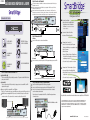
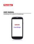
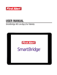
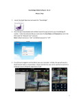
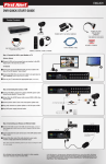
ENGLISH
DVR QUICK START GUIDE
Step 2: Connecting the Cameras*
1
2
3
Product Contents
Connect both ends of BNC cable from camera to both ends of the 60ft BNC cable labeled
"Camera Side”
Using other side of 60ft BNC cable labeled DVR side, connect BNC to BNC video input on DVR
Using the supplied Power splitter Cable, connect the red end to the DVR and one of the black
ends to each of the camera's power cables. Connect the single end of the Power splitter Cable
to the power supply. (repeat steps 1-3 for additional cameras)
2
MENU
1
2
3
4
ESC
1
2
3
4
3
1
DVR
WARNING
POWER SUPPLY*
DVR & CAMERAS
1
3
PC Connect Setup
• Insert SmartBridge Remote Software Installation
Disc into your computer or laptop
• Install Software
• Open Program
• Enter Unique System ID into the Device ID prompt,
Password is set to a default 123
• Select “Login” to access your system
4
Smartphone and Tablet Setup
• Download SmartBridge Mobile App
• Open App and enter Unique System ID into the Device ID prompt
• Select “Login” to access your system
1
16 Channel:
Connect the separately supplied DVR 4 Amp power supply to the DVR
POWER SPLITTER
Remote Software
Installation Disc
1
(HDMI or VGA Option) - Connect a HDMI or VGA cord (not included) from your monitor or TV to the
HDMI or VGA Output port on the back of your DVR
(BNC Option) - Connect the end of the BNC cable (not included) to the back of the BNC connection
on the DVR labeled “Video Output”
Connect the BNC cable to the BNC input on your TV/Monitor
(Note: If your TV or monitor does not have a BNC connection it is still possible to connect your DVR via the BNC output using a BNC-RCA adaptor
and cable (not included). This may be useful if you decide to connect a monitor or TV via each of the 3 Video out connections from your DVR.)
Turn on your TV/Monitor and select the appropriate input (noted above)
(4 Amp)
(3 Amp)
Step 1: Connect the DVR to your Monitor or TV
* 16 Channel DVR systems contain separate power supplies for cameras and DVR
Step 4: Connecting the Mouse and Ethernet Cable
1
2
3
Connect the USB mouse to the bottom USB slot on the back
Connect the Ethernet cable to the back of the DVR labeled either NET or RJ45
Connect the other end of the cable directly to your router, modem or high speed
internet connection input
Note: USB mouse and ethernet cable input locations may vary model to model.
BACK of DVR
1
Select the Network Tab. Your Unique
Device ID will be listed here.
8 Channel:
Connect the DVR to one of the multi-splitter ends
ETHERNET CABLE
STICKERS
1
1
2
Step 3: Powering the DVR*
REMOTE CONTROL &
USB 2.0 MOUSE
1
HDMI
2
VGA
3
(Note 8 Channel DVR shown. Your connections may be in different areas depending on your DVR model)
Power on the SmartBridge
• Right click anywhere on the screen
and select System Setup
(no password is required until you set one up)
(Attach for each camera)
(Power Splitter)
IR
Rec
PROTECTED BY
Easy Setup
1
Power
THESE PREMISES ARE UNDER
24 HOUR VIDEO SURVEILLANCE
REMOTE ACCESS
Go to firstalert.com to find complete instruction manual for your First Alert DVR.
© 2013 BRK Brands, Inc. All rights reserved. Distributed by BRK Brands, Inc., Aurora, Illinois
60504. Due to continuing product development, the product inside the packaging may look
slightly different than the one on the package. 1 Year Limited Warranty – see inside for details.
BRK Brands, Inc. is a subsidiary of Jarden Corporation (NYSE: JAH).
1
www.firstalert.com
ESPAÑOL
GUÍA DE INICIO RÁPIDO DE LA DVR
Step 2: Conectar las Cámaras*
Conecte ambos extremos del cable BNC de la cámara a ambos extremos del cable BNC de 60 pies
etiquetado “Camera Side”
2 Usando el extremo opuesto del cable BNC de 60 pies etiquetado “DVR Side” conecte el BNC a la
entrada de video BNC en la DVR
3 Usando el Cable divisor de Poder proporcionado, conecte el extremo rojo a la DVR y uno de los
extremos negros a cada uno de los cables de poder de la cámara. Conecte el extremo singular del
Cable Divisor de Poder a la fuente de poder. (Repita los pasos 1 a 3 para cámaras adicionales)
1
ACCESO REMOTO
Configuración Fácil
Contenido del Producto
1
2
Power
MENU
1
2
3
4
ESC
1
2
3
4
IR
Rec
Conectar para cada cámara)
(Divisor de Alimentación)
DVR
que usted configure una)
3
1
2
Seleccione la Pestaña de Red. Ahí se
mostrará su ID Única de Dispositivo.
3
Configuración de Conexión a PC
• Inserte el Disco de Instalación del Programa
Remoto de SmartBridge en su computadora o laptop
• Instale el Programa
• Abra el Programa
• Ingrese la ID Única de Sistema del Dispositivo en
la Casilla de ID de Dispositivo, la Contraseña está
configurada por defecto a 123
• Seleccione “Login” para acceder a su sistema
4
Configuración de Teléfono Inteligente y Tableta
• Descargue la Aplicación SmartBridge Móvil
• Abra la Aplicación e ingrese la ID Única de Sistema del Dispositivo en la Casilla de ID
de Dispositivo
• Seleccione “Login” para acceder a su sistema
Step 3: Alimentar la DVR*
CONTROL REMOTO
Y MOUSE USB 2.0
FUENTE DE PODER para
LA DVR Y LAS CÁMARAS
1
8 Canales:
Conecte la DVR a uno de los extremos del multi-divisor
4
WARNING
THESE PREMISES ARE UNDER
24 HOUR VIDEO SURVEILLANCE
PROTECTED BY
CALCOMANÍAS DE
SEGURIDAD
CABLE ETHERNET RJ45
1
1
16 Canales:
Conecte la fuente de poder de 4 Amperios de la DVR proporcionada por separado a la DVR
DIVISOR DE ALIMENTACIÓN
CALCOMANÍAS DE
SEGURIDAD
1
Paso 1: Conecte la DVR a su Monitor o TV
1
1
2
3
((Opción HDMI o VGA)
Conecte un cable HDMI o VGA (no incluido) de su monitor o TV al puerto de Salida HDMI o VGA en la
parte posterior de la DVR
(Opción BNC)
Conecte el extremo del cable BNC (no incluido) a la parte posterior de la conexión BNC en la DVR
etiquetada “Video Output”
Conecte el cable BNC a la entrada BNC en su TV/Monitor
(Nota: Si su TV o monitor no tiene una conexión BNC aun es posible conectar su DVR por medio de la
salida BNC usando un adaptador BNC-RCA y un cable (no incluidos). Esto puede ser útil si decide
conectar un monitor o TV a cada una de las 3 conexiones de salida de Video de la DVR).
(4 Amp)
(3 Amp)
* Los sistemas DVR de 16 Canales tienen fuentes de poder separadas para cámaras y la DVR
Step 4: Conectar el ratón y el Cable Ethernet
1
2
3
Conecte el ratón USB al puerto inferior USB en la parte posterior
Conecte el cable Ethernet en la parte posterior de la DVR etiquetada NET o RJ45
Conecte el otro extremo del cable directamente a su router, módem o entrada de
conexión a Internet de alta velocidad
Nota: la ubicación de las entradas del ratón USB y del cable Ethernet pueden variar
de un modelo a otro.
PARTE POSTERIOR de la DVR
1
1
HDMI
Encienda el SmartBridge
• Haga clic derecho en cualquier parte de
la pantalla y seleccione Configuración
de Sistema (no se requiere una contraseña hasta
2
VGA
3
Vaya a firstalert.com encontrar el manual de instrucciones completo de su DVR First Alert.
© 2013 BRK Brands, Inc. Todos los derechos reservados. Distribuido por BRK Brands, Inc.,
Aurora, Illinois 60504. Debido al desarrollo continuo del producto, el producto dentro del
empaque puede verse ligeramente diferente que al que se muestra en el empaque. Garantía
Limitada de 1 Año – vea adentro para los detalles. BRK Brands, Inc. es una subsidiaria de la
Corporación Jarden (NYSE: JAH).
1
www.firstalert.com
(Nota el Canal 8 DVR se muestra aqui. Su conexión puede ser diferente en ciertas areas dependiendo en el modelo de DVR)
M08-0486-000