Download manuale istruzioni livret d`instructions
Transcript
V. 005
I
GB
F
D
MANUALE
ISTRUZIONI
INSTRUCTIONS LIVRET
ANLEITUNGD’INSTRUCTIONS SHEFT
MANUAL
Scheda elettronica di controllo
per
1 attuatore
ROBO/OTTO
Electronic control
card for
1 actuator
ROBO/OTTO
Fiche
electronique de
controle pour 1
actionneur
ROBO/OTTO
Elektronischer
Kontrollkarte für
einen
Antriebszylinder
ROBO/OTTO
E
MANUAL DE
INSTRUCCIONES
Tarjeta
electrónica de
control para
1 accionador
ROBO/OTTO
QUESTO LIBRETTO È DESTINATO SOLO ALL'INSTALLATORE.
L'installazione dovrà essere effettuata solamente da personale professionalmente qualificato in conformità a quanto previsto
dalla legge n° 46 del 5 marzo 1990 e successive modifiche ed integrazioni e nel pieno rispetto delle norme UNI 8612.
Italiano
INTRODUZIONE:
La scheda elettronica è stata progettata per poter azionare gli attuatori “MOVO” serie “ROBO” ( scorrevoli ) e “OTTO” (basculanti).
E’ una scheda che permette azionamenti in modo “manuale” , “semiautomatico” oppure “automatico” con il controllo dei dispositivi
di sicurezza e dei limiti del movimento mediante finecorsa . Dispone di sofisticate funzioni di tipo logico che vanno dalla “Memoria del
movimento” fino alla “Richiudi subito dopo Foto” passando per la “Richiudi sempre” e di particolari funzioni di tipo operativo “Partenza
graduale” , “Fermata graduale” e “Freno”. E’ predisposta per l’inserimento della vasta gamma di ricevitori radio prodotti da Nice , e,
con l’inserimento della scheda espansioni modello “PIU’ “, si ampliano le funzioni attraverso altri ingressi ed altre uscite .
Nel progetto sono state adottate le piú avanzate tecniche per garantire la massima immunità nei confronti dei disturbi , la maggiore
flessibilità d’uso e la più vasta scelta di funzioni programmabili .
FUNZIONI PROGRAMMABILI :
Switch 1-2 :
Switch 3
Switch 4
Switch 5
Switch 6
Switch 7
Switch 8
Switch 9
Switch 10 (su ROBO)
Switch 10 (su OTTO)
Off
On
Off
On
On
On
On
On
On
On
On
On
On
Off
Off
On
On
=
=
=
=
=
=
=
=
=
=
=
=
=
Movimento “ Manuale “ ( Uomo Presente )
Movimento “ Semiautomatico “
Movimento “ Automatico “ ( Chiusura Automatica )
Movimento “ Automatico + Chiude Sempre “
Funzionamento Condominiale
Prelampeggio
Richiudi subito dopo Foto ( solo se in Automatico )
Sicurezza ( Foto ) anche in apertura
Partenza Graduale
Fermata Graduale ( funzione sconsigliata su ROBO )
Freno
Spia C.A. con lampeggio proporzionale
Tempo luce di cortesia = 4 minuti
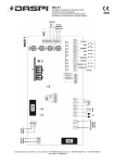
SCHEMA DEI COLLEGAMENTI :
Fig. 1
NOTA : L’installazione e i successivi interventi di manutenzione devono essere effettuati solo da personale qualificato ed esperto,
in conformità a quanto previsto dal DPR N°46 del 5/3/1990 , nel pieno rispetto delle norme UNI 8612 e seguendo le migliori indicazioni
dettate dalla “Regola d’arte” . Chi esegue detti interventi si rende responsabile di eventuali danni causati .
2
Italiano
DESCRIZIONE DEI COLLEGAMENTI :
1-2
: 220 Vac
= Alimentazione elettrica 220 Vca 50 Hz
3-4
: Lampeggiante
= Uscita per collegamento al lampeggiante 220 Vca
5-6
: 24 V~
= Uscita 24 Vac per alimentazione servizi ( Foto , Radio ecc ) massimo 200 mA
7
: Comune
= Comune per tutti gli ingressi ( come Comune è utilizzabile anche il morsetto 6 )
8
: Spia C.A.
= Uscita per spia cancello aperto 24 Vac massimo 2 W ( Non presente nelle schede serie OTTO)
9
: Alt
= Ingresso con funzione di ALT ( Emergenza , blocco o sicurezza estrema )
10
: Foto
= Ingresso per dispositivi di sicurezza ( Fotocellule , coste pneumatiche )
11
: Passo Passo
= Ingresso per funzionamento ciclico ( APRE STOP CHIUDE STOP )
12
: Apre
= Ingresso per movimento in apertura ( APRE STOP APRE )
13
: Chiude
= Ingresso per movimento in chiusura ( CHIUDE STOP CHIUDE )
41-42 : 2° Ch Radio
= Uscita dell’eventuale secondo canale del ricevitore radio
43-44 : Antenna
= Ingresso per antenna del ricevitore radio
Le rimanenti connessioni vengono già eseguite in sede di produzione , per completezza ne riportiamo l’elenco :
TRASFORM. PRIMARIO
= Primario del trasformatore di alimentazione
TRASF. SECON.
= Secondario del trasformatore di alimentazione
FINECORSA
= Ingresso dei finecorsa Apre , Chiude e Sblocco manuale
LUCE CORT.
= Uscita per lampada con funzione di luce di cortesia ( solo su OTTO)
MOTORE
= Uscita per collegamento motore
COND.
= Connessione del condensatore per il motore
Sono inoltre presenti due ulteriori innesti
RADIO
= Innesto per ricevitori radio prodotti da Nice
PIU’
= Innesto per scheda espansioni “ PIU’ “.
}
Attenzione a non confondere un innesto per l’altro
ISTRUZIONI PER I COLLEGAMENTI :
Per garantire l’incolumità dell’operatore e per prevenire danni ai componenti , mentre si effettuano i collegamenti , sia di bassa tensione
( 220 V ) che di bassissima tensione ( 24 V ) o si innestano le varie schede , la centrale non deve essere assolutamente alimentata
elettricamente .
Ricordiamo inoltre che gli ingressi dei contatti di tipo NC , se non usati , vanno ponticellati , se piú di uno vanno posti in SERIE tra di
loro ; gli ingressi dei contatti di tipo NA se non usati vanno lasciati liberi , se piú di uno vanno posti in PARALLELO tra di loro . Per quanto
riguarda i contatti questi devono essere assolutamente di tipo meccanico e svincolati da qualsiasi potenziale , non sono ammessi
collegamenti a stadi tipo quelli definiti “ PNP “ , “ NPN “ , “ Open Collector “ ecc.ecc.
A) Effettuare i collegamenti necessari seguendo lo schema di Fig 1 ; si ricorda che vi sono delle normative precise da rispettare in
modo rigoroso sia per quanto riguarda la sicurezza degli impianti elettrici che per quanto riguarda i cancelli automatici .
B ) Sbloccare il cancello e posizionarlo a metà della corsa , quindi bloccare nuovamente , in questo modo i due finecorsa risulteranno
liberi .
C ) Alimentare la centrale verificando immediatamente che sui morsetti 1-2 giunga una tensione di 220 Vca e che sui morsetti 5-6 sia
presente una tensione di 24 Vca . Non appena la centrale è alimentata le spie luminose ( LED ) che sono poste sugli ingressi attivi
devono illuminarsi , inoltre dopo pochi istanti il led “ OK “ dovrà iniziare a lampeggiare con cadenza regolare . Se tutto questo non
avviene , togliere immediatamente alimentazione e controllare con maggior attenzione i collegamenti .
3
Italiano
Il led “ OK “ posizionato al centro della scheda , ha il compito di segnalare lo stato della logica interna : un lampeggio regolare ed alla
cadenza di 1 secondo indica che il processore interno è attivo ed è in attesa di comandi .
Quando invece lo stesso processore riconosce una variazione dello stato di un ingresso ( sia ingresso di comando che Switch di
programmazione ) genera un doppio lampeggio veloce , questo anche se la variazione non provoca effetti immediati .
D ) Ora agire manualmente sulla leva dei finecorsa e verificare che agendo nel senso di apertura si spenga il led FCA e agendo nel
senso di chiusura si spenga il led FCC , se lo spegnimento è contrario , occorre spegnere l’alimentazione, quindi ruotare di 180° i
connettori FINECORSA e MOTORE , infine ricontrollare . Provare anche l’ingresso di ALT, questo interviene disattivando
simultaneamente sia FCA che FCC .
E ) Verificare il corretto funzionamento dei dispositivi di sicurezza ( fotocellule ,coste pneumatiche ecc. ) , ogni volta che intervengono,
il led FOTO deve spegnersi .
PROVA DI FUNZIONAMENTO:
Verificati i collegamenti è possibile provare il movimento dell’attuatore , si consiglia di operare in modo manuale con tutte le funzioni
disattivate ( tutti gli Switch Off ) ; per ogni eventualità , in modo manuale , rilasciando il tasto di comando si ottiene l’immediato arresto
del motore .
Se si usa come comando l’ingresso Passo P. il primo movimento ( dopo l’accensione ) dovrà essere in apertura . Agendo sugli ingressi
di comando movimentare il cancello fino all’intervento del finecorsa FCA , questo dovrà fermare il movimento . Eseguire un movimento
in chiusura al fine di provare l’intervento del finecorsa FCC , anche questo dovrà provocare l’arresto del movimento . Per ultimo provare
l’intervento dei dispositivi di sicurezza , in apertura non hanno effetto , in chiusura provocano la fermata del movimento .
Le normative UNI 8612 prescrivono che la spinta massima del cancello non superi i 150 N ( ~ 13,5 Kg ) questo si ottiene mediante
la regolazione della frizione meccanica negli attuatori predisposti , mentre negli altri si interviene per via elettrica od elettronica . Se
sulla scheda è presente il trimmer FORZA la regolazione è di tipo elettronico ( a parzializzazione di fase ) agire su detto trimmer per
regolare la forza .
ATTENZIONE : se ad inizio del movimento il trimmer è regolato per il massimo , la forza rimane massima per tutto il movimento,
occorre allora regolare il trimmer per esempio al 70% , poi avviare il movimento , quindi agire sul trimmer per ottenere un immediato
riscontro .
Nel caso invece sia presente il trasformatore dotato di commutatore “ FORZA” selezionare il livello necessario .
In entrambe i casi ad inizio del movimento verrà eseguito uno SPUNTO a forza massima per consentire l’avviamento del motore, solo
dopo 1,5 secondi verrà attivata la regolazione di forza stabilita .
Se si desidera il funzionamento in semiautomatico od automatico sarà necessario passare alla regolazione dei tempi di LAVORO
( TL ) e di PAUSA ( TP ). Il TL va di norma regolato con 3÷5 Sec di margine sul tempo necessario all’intero movimento , per la
regolazione procedere per tentativi successivi partendo dal minimo ed aumentare via via il tempo , fare una manovra completa prima
di valutare il risultato . Nel caso il tempo massimo non fosse sufficiente tagliare TLM per aumentare ulteriormente il tempo . Il TP viene
usato nel movimento in automatico per stabilire il tempo che deve trascorrere tra la fine della manovra di apertura e la successiva
richiusura . Viene usato anche nel movimento in semiautomatico quando , in chiusura , l’intervento di un dispositivo di sicurezza
provoca una inversione in apertura .
Consigliamo di inserire l’eventuale ricevitore radio solo al termine di tutte le regolazioni e solo dopo aver tolto l’alimentazione elettrica
PROGRAMMAZIONE :
Mediante gli switch è possibile configurare i vari parametri di funzionamento
Switch 1 - 2: Off
On
Off
On
Off
Off
On
On
= Movimento “ Manuale “ ( Uomo Presente )
= Movimento “ Semiautomatico “
= Movimento “ Automatico “ ( Chiusura Automatica )
= Movimento “ Automatico + Chiude Sempre “
Nel funzionamento in Manuale il movimento viene eseguito solo fino alla presenza del comando ( tasto premuto ) ;
In Semiautomatico basta un impulso di comando e viene eseguito tutto il movimento fino all’intervento del finecorsa o allo scadere
del tempo di lavoro programmato . Nel funzionamento Automatico dopo una apertura viene eseguita una pausa e quindi una chiusura.
La funzione “ Chiude Sempre “ interviene se , dopo una mancanza momentanea di alimentazione , non viene rilevato ( attraverso FCC)
il cancello chiuso ; in questo caso si avvia automaticamente una manovra di chiusura preceduta da 5 secondi di prelampeggio .
Switch 3 :
On
= Funzionamento Condominiale
Nel funzionamento condominiale , una volta avviato un movimento in apertura con un ingresso Apre o Passo P. questa non puó piú
essere interrotta da altri comandi sugli stessi ingressi fino alla fine del movimento in apertura .
4
Italiano
Switch 4:
On
= Prelampeggio
Viene attivato il lampeggiante 5 secondi prima di iniziare il movimento ( ridotto a 2 secondi se in modo manuale ) .
Switch 5 :
On
= Richiudi subito dopo Foto ( solo se in automatico : Sw 2 = On )
Nel funzionamento in automatico la chiusura avverrà 5 secondi dopo il disimpegno del dispositivo di sicurezza , indipendentemente
dal TP programmato .
Switch 6 :
On
= Sicurezza ( Foto ) anche in apertura
L’intervento del dispositivo di sicurezza in apertura provoca una interruzione del movimento , se in Semiautomatico od Automatico
si avrà la ripresa del moto in apertura subito dopo il disimpegno .
Switch 7 :
On
= Partenza Graduale
Esegue l’inizio del movimento in modo graduale evitando scossoni al cancello .
Switch 8 :
On
= Fermata Graduale
Esegue la fermata del movimento in modo graduale evitando scossoni al cancello .
VALUTARE CON ATTENZIONE l’effetto della funzione : una volta inserita il movimento può continuare per circa 2 secondi oltre
il punto di intervento dei finecorsa , ( sconsigliato su ROBO).
Switch 9 :
On
= Freno
Al termine del movimento viene eseguita una procedura di freno al motore , inizialmente blanda poi piú incisiva in modo di fermare
il cancello velocemente ma senza scossoni.
Switch 10 :
On ROBO
= Spia C.A. con lampeggio proporzionale
Il lampeggio della spia C.A durante il movimento è proporzionale alla posizione del cancello stesso ( inserire la funzione solo se il
movimento è superiore a 10 secondi )
Switch 10 :
On OTTO
= Tempo luce di cortesia = 4 minuti
Permette di aumentare da 1 a 4 minuti il tempo della luce di cortesia .
DESCRIZIONE DEI MODI DI FUNZIONAMENTO:
Nel funzionamento in modo manuale , l’ingresso APRE consente il movimento in apertura , l’ingresso CHIUDE consente il movimento
in chiusura , il PASSO P. consente il movimento alternativamente in apertura e in chiusura ; non appena cessa il comando in ingresso
il movimento si arresta ; l’ingresso APRE PARZIALE ( scheda espansioni ) non ha alcun effetto . In apertura il movimento si arresta
se manca il consenso dal finecorsa FCA o dalla FOTO 2 ( scheda espansioni ) in chiusura invece il movimento si arresta se manca
il consenso dal finecorsa FCC o dalla FOTO . Un intervento su ALT provoca un immediato arresto del movimento , questo sia in
apertura che in chiusura . Una volta che il movimento si è arrestato è necessario cessare il comando in ingresso prima di poter iniziare
un nuovo movimento .
Nel funzionamento in uno dei modi automatici ( semiautomatico - automatico e chiude sempre ) un impulso di comando sull’ingresso
APRE provoca il movimento in apertura , un impulso su CHIUDE provoca la chiusura mentre un impulso su PASSO P. provoca
alternativamente apertura o chiusura . Un secondo impulso sul PASSO P. o sullo stesso ingresso che ha iniziato il movimento provoca
uno Stop , un secondo impulso sull’ingresso opposto a quello che ha iniziato il movimento provoca una inversione del moto .Un
intervento su ALT provoca un immediato arresto del movimento , questo sia in apertura che in chiusura
Se in un ingresso di comando invece di un impulso viene mantenuto un segnale continuo , questo provoca uno stato di “prevalenza”
in qui gli altri ingressi di comando rimangono disabilitati ( utile per collegare direttamente un orologio programmatore o un selettore
Notte-Giorno ) .
In apertura il movimento si arresta se manca il consenso dal finecorsa FCA in chiusura invece il movimento si arresta se manca il
consenso dal finecorsa FCC ; in tutti i casi il movimento termina al cessare del tempo lavoro TL programmato .
Se il movimento viene interrotto prima della fine naturale ( finecorsa o termine del TL ) il movimento non eseguito viene memorizzato
e se ne terrà contro nella manovra successiva ( particolarmente utile su OTTO quando non vengono utilizzati i finecorsa ) .
Nel caso fosse inserito il modo di funzionamento automatico , dopo una manovra di apertura , viene eseguita una pausa con un tempo
pari a TP , al termine viene eseguita una chiusura . Se durante la pausa vi fosse un intervento di FOTO , il temporizzatore verrà
ripristinato con un nuovo tempo ; se invece durante la pausa si interviene su ALT la funzione di richiusura viene cancellata e si passa
in uno stato di STOP .
5
Italiano
In apertura l’intervento della FOTO non ha effetto mentre la FOTO 2 ( scheda espansioni ) provoca l’inversione del moto ; in chiusura
l’intervento dalla FOTO provoca una inversione del moto quindi una nuova pausa TP , infine una richiusura . Se all’inizio del movimento
in apertura l’ingresso FOTO non da il consenso la richiesta di apertura viene annullata .
SCHEDA ESPANSIONI “ PIU' “
La centrale elettronica dispone di tutte le principali funzioni richieste in una normale automazione , è stata comunque progettata una
scheda aggiuntiva che permette di aumentare le prestazione della centrale .
La scheda va innestata nell’apposito connettore , sui propri morsetti sono disponibili i seguenti ulteriori ingressi :
Foto 2
Apre Parziale
= Dispositivo di sicurezza con intervento nella manovra di apertura
= Esegue una manovra di apertura con un tempo ridotto
delle seguenti uscite :
Rosso
Verde
Elettroserratura
Luce di Cortesia
= Luce rossa del semaforo (Allarme)
= Luce verde del semaforo (Allarme)
= Comando della elettroserratura
= Comando di una lampada con funzione di luce di cortesia
e delle seguenti regolazioni :
Tempo Parziale
Tempo Cortesia
= Tempo per l’apertura parziale
= Tempo per la luce di cortesia
Nota : Le uscite possono comandare solo carichi di piccola potenza ( lampade spia , relè ecc.)
CARATTERISTICHE TECNICHE DELLA CENTRALE :
Alimentazione
: 220 Vac ±10% , 50 Hz
Corrente Max servizi 24 V
: 200 mA
Potenza massima spia CA : 2W ( 24 Vac )
6
Tempo lavoro
: da 2,5 a 50 Sec. ( da 20 a 75 Sec. con TLM )
Tempo pausa
: da 5
Tempo spunto
: 1,5 Sec.
Temperatura di esercizio
: -20 ÷ 70 °C
a 100 Sec.
English
INTRODUCTION:
The electronic card was designed to operate the “MOVO” actuators of the “ROBO” (sliding) and “OTTO” (pivoting) series.
This card allows the actuators to be operated in “manual”, “semiautomatic” or “automatic” mode, with control of the safety devices and
movement limits via the stroke ends. It is equipped with sophisticated logic functions ranging from “movement memory” to “close again
immediately after photocell” passing through “always close” and the specific operational functions “gradual start”, “gradual stop” and
“brake”. It is designed to be fitted with a wide range of radio receivers manufactured by Nice, and, with the insertion of the expansion
card “PIU’ ”, functions are expanded with other inputs and outputs.
The project has been designed using the most modern techniques in order to guarantee maximal immunity from disturbances, utmost
flexibility of use and the widest choice of programmable functions.
PROGRAMMABLE FUNCTIONS
Switch 1-2:
Switch 3
Switch 4
Switch 5
Switch 6
Switch 7
Switch 8
Switch 9
Switch 10
Switch 10
Off Off
On Off
Off On
On On
On
On
On
On
On
On
On
(on ROBO) On
(on OTTO) On
= “Manual” movement (person present)
= “Semiautomatic” movement
= “Automatic” movement (Automatic closing)
= “Automatic” movement + “Always close”
= Shared property operation
= Pre-flash
= Close again immediately after Photocell (only if in automatic mode)
= Safety device (photocell) also on opening
= Gradual start
= Gradual stop (not recommended on ROBO)
= Brake
= Gate open pilot light with proportional flash
= Courtesy light time = 4 minutes
CONNECTION DIAGRAM:
Fig. 1
NOTE: Installation and subsequent maintenance operations must be carried out only by professionally qualified personnel, in
accordance with the provision of national laws, in full compliance with the UNI 8612 regulations and following the foremost indications
prescribed by the “Workmanlike” rules. The person carrying out said operations is responsible for any damages caused.
7
English
DESCRIPTION OF THE CONNECTIONS:
1-2:
220 Vac
= Electric power 220 Vac 50 Hz
3-4:
Flash
= Output for connection to flash 220 Vac
5-6:
24 V
= Output 24 Vac for powering services (Photocell, Radio, etc.) maximum 200 mA
7:
Normal
= Normal for all inputs (terminal 6 can also be used as Normal)
8:
G.A. light
= Output for gate open pilot light 24 Vac (maximum 2 W) (not present on the
OTTO series cards)
9:
Alt
= Input with ALT function (Emergency, lock or safety limit)
10:
Photocell
= Input for safety devices (photocells, pneumatic ribs)
11:
Step by Step
= Input for cyclic operation (OPEN STOP CLOSE STOP)
12:
Open
= Input for opening movements (OPEN STOP OPEN)
13:
Close
= Input for closing movements (CLOSE STOP CLOSE)
41-42:
2nd Radio Ch
= Output for any second radio receiver channel
43-44:
Aerial
= Input for radio receiver aerial
The following connections are made during manufacture and are listed for information:
PRIMARY TRANSFORM.
= Primary of the feed transformer
SECOND TRANSF.
= Secondary of the feed transformer
STROKE END
= Inputs of the Open, Close and Manual Release stroke ends
COURT. LIGHT
= Output for lamp functioning as courtesy light (only on OTTO)
MOTOR
= Output for motor connection
CAPAC.
= Connection for motor capacitor
Two further connections are also present:
RADIO
= Connection for radio receivers manufactured by Nice
PIU’
= Connection for “PIU’ ” expansion card.
}
(Take care not to confuse these
two connections)
CONNECTION INSTRUCTIONS:
To safeguard the operator and prevent damage to components the central unit MUST always be disconnected from the power
supply while effecting low voltage (220 V) and extremely low voltage (24V) connections, or inserting the different cards.
Also remember that jumpers must be fitted to the NC contact inputs not in use and, if more than one, positioned in SERIES with each
other; the NA contact inputs not in use are left free and, if more than one, positioned PARALLEL with each other. As regards the
contacts, these must always be the mechanical type and free of any potential; stage connections such as the types defined as “PNP”,
“NPN”, “Open Collector” etc. are not allowed.
A) Make the necessary connections following the diagram in Fig. 1; bear in mind that there are regulations which must be strictly
adhered to, both as regards the safety of electric systems as well as automatic gates.
B) Release the gate, position it in the middle of its stroke, and lock it again, so that the two stroke ends are free.
C) Power the central unit, immediately checking that the terminals 1-2 are supplied with a voltage of 220 Vac and terminals 5-6 with
a voltage of 24 Vac. As soon as the central unit is powered the pilot lights (LEDs) positioned on the active inputs must light up, and
after a few moments, the “OK” LED must start flashing at regular intervals. Should there be any discrepancy in this procedure
immediately disconnect the power supply and check the connections more carefully.
8
English
The “OK” LED positioned in the centre of the card has the function of signalling the state of the internal logic: regular flashing at intervals
of 1 second indicates that the internal processor is active and awaiting commands.
However, when the processor detects a variation in the input state (either a command input or a programming Switch) it generates
a fast, double flash, even if the variation has no immediate effect.
D) Now turn the lever of the stroke ends manually and check that by turning in the opening direction the FCA (stroke end open) LED
switches off and by turning in the closing direction the FCC (stroke end close) LED switches off. Should the opposite occur, it is
necessary to disconnect the power supply, then rotate the STROKE END and MOTOR connectors through 180° and lastly check
again. Also check the ALT input, this operates deactivating FCA and FCC simultaneously.
E) Check that the safety devices (photocells, pneumatic ribs, etc.) function correctly. Each time these operate the PHOTOCELL LED
must switch off.
OPERATION TESTS:
Once the connections have been made and checked it is possible to test actuator movement. It is advisable to operate in manual
mode with all the functions deactivated (all switches OFF), so that, if necessary,in manual mode, when the control key is released
the motor stops immediately. If Passo P. (Step by Step) is used as the input command an opening movement should be obtained
first (after switching on). Use the command inputs to move the gate until operation of the FCA (stroke end open), which should stop
movement. Make a closing movement to test operation of the FCC (stroke end close), which should also stop movement. Lastly, test
operation of the safety devices: these have no effect during opening and stop movement during closing.
The UNI 8612 regulations prescribe that the maximum gate thrust must not exceed 150 N (13.5 kg), which can be obtained by adjusting
the mechanical clutch in actuators equipped with this, while in others electric or electronic adjustment is necessary. If there is a FORCE
trimmer on the card adjustment is electronic (with phase-sharing); use the trimmer to adjust the force.
WARNING: if the trimmer is adjusted to maximum, at the beginning of movement the force remains at maximum for the entire
movement. The refore, it is necessary to adjust the trimmer, i.e. to 70%,subsequently start the movement, then adiust the trimmer
to obtain an immediate check.
In the event of a transformer equipped with a “FORCE” switch select the necessary level.
In both cases at the beginning of movement there will be a SPURT at maximum force to allow the motor to start; the set force
adjustment will be activated only after 1.5 seconds.
If semiautomatic or automatic operation are required it is necessary to adjust the WORKING (TL) and PAUSE (TP) times. TL is
normally adjusted with a margin of 3-5 seconds on the time necessary for the entire movement. To adjust it start out from minimum
and make several attempts, increasing the time with each attempt. Perform a complete movement before assessing the result. If the
maximum time is not sufficient cut the TLM to further increase the time. The TP is used in automatic movement to establish the time
which must elapse between the end of the opening manoeuvre and the subsequent closing one. It is also used in semiautomatic
movement when the operation of a safety device triggers a reversal from closing to opening.
We recommend fitting the radio receiver, if envisaged, only after having made all the adjustments and disconnected the power supply.
PROGRAMMING:
It is possible to set the various operation parameters via the switches.
Switch 1-2:
Off Off
On Off
Off On
On On
= “Manual” movement (person present)
= “Semiautomatic” movement
= “Automatic” movement (automatic closing)
= “Automatic” movement + “Always Close”
In Manual operation the movement is performed only while the command is present (key pressed).
In Semiautomatic operation only a command impulse is necessary and the entire movement is performed either until it reaches the
stroke end or until the set working time expires. In Automatic operation the opening movement is followed by a pause and then a closing
movement.
The “Always Close” function is activated if, after a momentary loss of power, the gate closed signal is not detected (via the FCC (stroke
end close)); in this case an automatic closing manoeuvre starts after 5 seconds of pre-flashing.
Switch 3:
On
= Shared property operation
In shared property operation once an opening movement is started with an Open or Step by Step input, this cannot be interrrupted
by other commands on the same inputs until the end of the opening movement.
Switch 4:
On
= Pre-flash
The flashing light is activated 5 seconds before movement starts (decreased to 2 seconds in manual mode).
9
English
Switch 5:
On
= Close again immediately after Photocell (only in automatic mode: Sw 2 = On)
In automatic operation closing occurs 5 seconds after the safety device is released, independently of the set TP (pause time).
Switch 6:
On
= Safety (photocell) also in opening
The intervention of the safety device during opening triggers an interruption in movement; if in Semiautomatic or Automatic Mode
movement will restart immediately after release.
Switch 7:
On
= Gradual Start
This starts the movement gradually to prevent the gate from jolting.
Switch 8:
On
= Gradual Stop
This stops the movement gradually to prevent the gate from jolting.
CAREFULLY ASSESS the effect of the function: once introduced the movement can continue for about 2 seconds after the point in
which the stroke ends are operational (not recommended on ROBO).
Switch 9:
On
= Brake
A braking procedure is applied to the motor at the end of the movement, starting off gently and increasing in strength so that the gate
is stopped quickly but without any jolting.
Switch 10:
On
ROBO = Gate open pilot light with proportional flash
The Gate Open pilot light flash is proportional to the position of the gate itself (introduce this function only if the movement time exceeds
10 seconds).
Switch 10:
On
OTTO = Courtesy light time = 4 minutes
This allows the courtesy light time to be increased from 1 to 4 minutes.
DESCRIPTION OF THE OPERATION MODES:
In manual operation mode, the OPEN input enables opening movement, the CLOSE input enables closing movement, the STEP BY
STEP enables alternative movement during opening and closing. As soon as the input command stops the movement stops; the
PARTLY OPEN input (expansion card) has no effect. Opening movement is stopped if it is not enabled by the FCA (stroke end open)
or PHOTOCELL 2 (expansion card) inputs. However, closing movement is stopped if it is not enabled by the FCC (stroke end close)
or PHOTOCELL inputs. By operating ALT movement is immediately halted, both during opening and closing. Once the movement has
been stopped it is necessary to stop giving the input command before another movement can start.
In one of the automatic operation modes (semiautomatic, automatic and always close) a command impulse on the OPEN input triggers
an opening movement, an impulse on the CLOSE input triggers closing and an impulse on the STEP BY STEP input triggers opening
or closing alternatively. A second impulse either on the STEP BY STEP input or on the same input which started the movement triggers
a stop, a second impulse on the opposite input from the one which started the movement triggers a reversal of direction. By operating
ALT movement is immediately halted, both during opening and closing.
If a continual signal is maintained instead of an impulse in a command input, this triggers a state of “prevalence” in which the other
command inputs remain disabled (useful for direct connection of a timer or Night-Day selector).
Opening movement is stopped if it is not enabled by the FCA (stroke end open) input; however, closing movement is stopped if it is
not enabled by the FCC (stroke end close) input; movement terminates in any case when the set TL (working time) expires.
If the movement is interrupted before the normal end (stroke end or end of working time TL) the movement which is not performed
is memorised and will be taken into account in the subsequent manoeuvre (particularly useful on OTTO when stroke ends are not
used).
If automatic operating mode is set, after an opening manoeuvre, there is a pause of the same length as the set pause time TP, after
which a closing movement is performed. If the PHOTOCELL operates during the pause, the timer is restored with a new time; if ALT
is operated during the pause, the re-closing operation is cancelled and a state of STOP is obtained.
During opening PHOTOCELL operation has no effect, while PHOTOCELL 2 (expansion card) triggers a reversal of direction; during
closing PHOTOCELL operation triggers a reversal in direction, followed by a new TP pause and another closing movement. If the
opening movement is not enabled by the PHOTOCELL input at the start, the request is cancelled.
10
English
EXPANSION CARD “PIU’ ”
The electronic central unit is equipped with all the main functions required in normal automation; however, an additional card has been
designed in order to increase the performance of the central unit.
The card is inserted into the dedicated connector and the following additional inputs are available on its terminals:
Photocell 2
Partial Open
= Safety device which operates during opening manoeuvre
= Performs an opening manoeuvre in reduced time
Red
Green
Electrolock
Courtesy light
= Red traffic light (alarm)
= Green traffic light (alarm)
= Command of electrolock
= Command of a lamp acting as a courtesy light
Partial time
Courtesy time
= Partial opening time
= Courtesy light time
Outputs:
Adjustments:
N.B. The outputs can only command charges with small voltages (pilot lights, relays, etc.).
TECHNICAL SPECIFICATIONS OF THE CENTRAL UNIT:
Power supply
: 220 Vac±10%, 50Hz
Max current 24 V services
: 200 mA
Max gate open pilot light power
: 2W (24 Vac)
Work time
: from 2.5 to 50 secs. (from 20 to 75 secs. with TLM)
Pause time
: from 5 to 100 secs.
Spurt time
: 1.5 secs.
Working temperature
: -20 to 70°C
11
Français
INTRODUCTION:
La fiche a été projetée pour pouvoir actionner des actionneurs “MOVO” série “ROBO” (coulissants) et “OTTO” (basculants).
C’est une fiche qui permet d’actionner les actionneurs en mode “manuel”, “semi-automatique” ou “automatique” avec le contrôle des
dispositifs de sécurité et des limites de mouvement par microinterrupteur de fin de course. Elle dispose de fonctions sophistiquées
de type logique qui vont de la “Memoire du mouvement” jusqu’à la “Referme juste après Photo” en passant par celle de “Referme
toujours” et de particulièrees fonctions de type opératif “Départ graduel”, “Fermeture graduelle” et “Frein”. Elle est prédisposée pour
l’insertion de la vaste gamme de récepteurs radio produits par Nice , et, avec l’insertion de la fiche d’expansions modèle “PIU’”,
on augmente les fonctions avec d’autres entrées et d’autres sorties.
Dans le projet, on a adopté les techniques les plus avancées pour garantir l’immunité maximum par rapport aux dérangements, la
majeure flexibilité d’utilisation et le plus vaste choix de fonctions programmables.
FONCTIONS PROGRAMMABLES
Int 1-2:
Off Off
Off Off
Off On
On On
Int 3
On
Int 4
On
Int 5
On
Int 6
On
Int 7
On
Int 8
On
Int 9
On
Int 10 (sur ROBO) On
Int 10 (sur OTTO ) On
= Mouvement manuel (Homme Présent)
= Mouvement semi-automatique
= Mouvement automatique (Fermeture automatique)
= Mouvement + Ferme toujours
= Fonctionnement en coproprieté
= Pré-clignotement
= Referme tout de suite après Photo (uniquement si en automatique)
= Sécurité (Photo) même en ouverture
= Départ graduel
= Arrêt graduel (déconseillé sur ROBO)
= Frein
= Lampe témoin C.A. avec clignotement proportionnel
= Temps lumière de courtoisie = 4 minutes
SCHEMA DES CONNEXIONS
Fig. 1
NOTA: L’installation et les interventions successives d’entretien doivent être effectuées uniquement par le personnel qualifié et expert,
conformément aux normes et d’après les dispositions des lois nationales dans le respect des normes UNI 8612 et en suivant les
meilleures indications dictées par la “Règle d’art”. Ceux qui exécutent de telles interventions se rendent responsables d’éventuels
endommagements.
12
Français
DESCRIPTION DES CONNEXIONS
1-2
: 220 Vac
= Alimentation électrique 220 Vca 50 Hz
3-4
: Clignotant
= Sortie pour connexion au clignotant 220 Vca
5-6
: 24V-
= Sortie 24 Vac pour alimentation des services (Photo, Radio, etc.) maximum 200 mA
7
: Commun
= Commun à toutes les entrées (comme commun on peut utiliser également la borne 6)
8
: Témoin C.A. = Sortie pour témoin du portail ouvert 24 Vac (maximum 2W) (Non présent dans les fiches de
la série OTTO )
9
: ALT
= Entrée avec fonction de ALT (Urgence, blocage ou sécurité extrême).
10
: Photo
= Entrée pour dispositifs de sécurité (photocellules, côtes pneumatiques)
11
: Pas Pas
= Entrée pour fonctionnement cyclique (OUVRE STOP OUVRE)
12
: Ouvre
= Entrée pour mouvement en ouverture (OUVRE STOP OUVRE)
13
: Ferme
= Entrée pour mouvement en fermeture (FERME STOP FERME)
41-42
: 2° ch Radio = Sortie du second canal éventuel du récepteur radio
43-44
: Antenne
= Entrée pour antenne du récepteur radio
Les connexions restantes sont déjà effectuées au siège de production; pour compléter le tout, nous en reportons la liste:
TRANSFORMATEUR PRIMAIRE
= Primaire du transformateur d’alimentation
TRANSFORMATEUR SECONDAIRE
= Secondaire du transformateur d’alimentation
FIN DE COURSE
= Entrée de fin de course Ouvre, Ferme, et déblocage manuel
LUMIERE DE COURTOISIE
= Sortie pour lampe avec fonction de lumière de courtoisie (uniquement sur OTTO)
MOTEUR
= Sortie pour connexion moteur
CONDENSATEUR
= Connexion du condensateur pour le moteur
En outre deux autres branchements sont présents:
RADIO = Branchement pour récepteurs radio produits par Nice
PIU’
= Branchement pour fiche à expansions “PIU’”
}
Attention à ne pas confondre un
branchement avec l’autre
INSTRUCTIONS POUR LES CONNEXIONS
Pour garantir la sécurité de l’opérateur et pour prévenir des endommagements aux composants, aussi bien à basse tension (220V)
qu’à très basse tension (24V) ou lorsqu’on branche les différentes fiches, la centrale ne doit absolument pas être alimentée
électriquement.
On rappelle en outre que les entrées des contacts du type NC, si non utilisées, sont des liaisons volantes, si elles sont plus d’une,
elles sont mises en série entre elles; les entrées des contacts du type NA, si elles ne sont pas utilisées, sont laissées libres, si elles
sont plus d’une, elles sont mises en parallèle entre elles. Pour ce qui est des contacts, ils doivent être du type mécanique et ne pas
être reliés à un potentiel; il n’est pas possible de faire des connexions en stades du type de ceux qui ont été définis “PNP”, “NPN”,
“Open Collector”, etc.
A) Effectuer les connexions nécessaires en suivant le schéma de l’ill.1; on rappelle que des normes précises existent et qu’elles doivent
être respectées de façon rigoureuse aussi bien en ce qui concerne la sécurité des installations électriques que les portails
automatiques.
B) Débloquer le portail et le positionner à la moitié de la course, puis bloquer de nouveau; de cette façon, les deux fins de course sont
libres.
C) Alimenter la centrale en vérifiant immédiatement que sur les deux bornes 1-2 arrive une tension de 220 Vca et que sur les bornes
13
Français
5-6 est présente une tension de 24 Vca. Dès que la centrale est alimentée, les témoins lumineux (LED) qui sont placés sur les entrées
actives doivent s’illuminer, en outre après quelques instants, le LED “OK” doit commencer à clignoter avec une cadence régulière.
Si tout cela ne se produit pas, enlever immédiatement l’alimentation et contrôler avec plus d’attention les connexions.
Le LED “OK” positionné au centre de la fiche a pour but de signaler l’état de la logique interne: un clignotement régulier et à un rythme
d’une seconde indique que le processeur interne est actif et dans l’attente de commandes.
Lorsque au contraire le processeur reconnaît une variation de l’état de l’une des entrées, (aussi bien entrée de commande
qu’interrupteur de programmation) il provoque un double clignotement rapide, ceci même si la variation ne provoque pas d’effets
immédiats.
D) Maintenant agir manuellement sur le levier de fin de course et vérifier qu’en agissant dans le sens de l’ouverture le LED “FCA”
s’éteint et qu’en agissant dans le sens de fermeture, le LED “FCC” s’éteint, si l’extinction est contraire, il faut éteindre l’alimentation
puis tourner de 180° les connecteurs MICROINT DE FIN DE COURSE et MOTEUR, puis recontrôler. Essayer aussi l'entrée de ALT
celle-ci intervient en désactivant simultanément aussi bien FCA que FCC.
E) Vérifier le fonctionnement correct des dispositifs de sécurité (Photocellules, côtes pneumatiques, etc.), à chaque fois qu’ils
interviennent, le LED “PHOTO” doit s’éteindre.
ESSAI DE FONCTIONNEMENT
Lorsque les connexions sont faites et vérifiées, il est possible d’essayer le mouvement de l’actionneur; on conseille d’opérer
manuellement et avec toutes les fonctions désactivées (tous les interrupteurs sur Off); pour toute éventualité, en mode manuel, de
cette façon, en relâchant la touche de commande on obtient l’arrêt immédiat du moteur. Si on utilise comme commande l’entrée Pas
P, le premier mouvement (après la mise en route) devra être en ouverture. En agissant sur les entrées de commande, mettre en
mouvement le portail jusqu’à l’intervention de fin de course FCA, ceci doit provoquer l’arrêt du mouvement. Exécuter un mouvement
de fermeture afin d’essayer l’intervention de fin de course FCC, ceci également devra provoquer l’arrêt du mouvement. Enfin, essayer
l’intervention des dispositifs de sécurité, en ouverture ils n’ont aucun effet, en fermeture, ils provoquent l’arrêt du mouvement.
Les normes UNI 8612 prescrivent que la poussée maximum du portail ne dépasse pas les 15 N (~ 13,5 Kg). Ceci s’obtient par
l’intermédiaire du réglage de la friction mécanique pour les actionneurs prédisposés, alors que pour les autres, on intervient
électriquement ou électroniquement. Si sur la fiche est présent le trimmer FORCE, le réglage est du type électronique (à
schématisation de phases); agir sur le trimmer pour régler la force.
ATTENTION: si au début du mouvement, le trimmer est réglé pour la force maximum, elle reste au maximum pendant tout le
mouvement; il faut alors régler le trimmer par exemple à 70% puis démarrer le mouvement et agir ensuite sur le trimmer pour obtenir
une réponse immédiate.
Au cas où au contraire est présent le transformateur doué de commutateur “FORCE”, sélectionner le niveau nécessaire.
Dans les deux cas, au début du mouvement, on exécutera une REPRISE à la force maximum pour permettre la mise en route du
moteur; seulement après 1,5 secondes le réglage de la force établie sera activé.
Si on désire le fonctionnement semi-automatique ou automatique, il sera nécessaire de passer au réglage des temps de TRAVAIL
(TL) et de PAUSE (TP). Le TL est en général réglé avec 3÷5 sec. de marge sur le temps nécessaire pour tout le mouvement; pour
le réglage procéder par des tentatives successives en partant du minimum et augmenter petit à petit le temps; faire une manœuvre
complète avant d’évaluer le résultat. Si le temps maximum n’est pas nécessaire, couper TLM pour augmenter ultérieurement le temps.
Le temps TP est utilisé dans le mouvement automatique pour établir le temps qui doit passer entre la fin de la manœuvre d’ouverture
et la fermeture successive. Il est également utilisé dans le mouvement semi-automatique quand, en fermeture, l’intervention d’un
dispositif de sécurité provoque une inversion en ouverture.
On conseille d’insérer l’éventuel récepteur radio seulement à la fin de tous les réglages et seulement après avoir enlevé l’alimentation
électrique.
PROGRAMMATION:
Par l’intermédiaire des interrupteurs il est possible de configurer les différents paramètres de fonctionnement.
Interrupteurs 1-2:
Off Off
On Off
Off On
On On
= Mouvement “Manuel” (Homme présent)
= Mouvement semi-automatique
= Mouvement “Automatique” (Fermeture Automatique)
= Mouvement “Automatique+ Ferme toujours”
Dans le fonctionnement manuel le mouvement est exécuté uniquement jusqu’à la présence de la commande (touche pressée);
En semi-automatique, il suffit d’une impulsion de commande et tout le mouvement est exécuté jusqu’à l’intervention de la fin de course
ou jusqu’à l’expiration du temps de travail programmé. Dans le fonctionnement automatique après une ouverture il y a une pause puis
la fermeture.
La fonction “Ferme toujours” intervient si, après un manque momentané d’alimentation, le portail fermé (par l’intermédiaire FCC) n’est
pas relevé; dans ce cas une manœuvre de fermeture automatique s’actionne automatiquement précédée de 5 secondes de préclignotement.
14
Français
Interrupteur 3:
On
= Fonctionnement en copropriété
Dans le fonctionnement en copropriété, dès que le mouvement d’ouverture avec une entrée Ouvre ou Pas P est actionné, on ne peut
plus l’interrompre avec d’autres commandes sur les mêmes entrées jusqu’à la fin du mouvement d’ouverture.
Interrupteur 4:
On
= Pré-clignotement
Le clignotant est activé 3 secondes avant de commencer le mouvement (réduit à 2 secondes si exécuté manuellement).
Interrupteur 5:
On
= Referme tout de suite après Photo (uniquement si en automatique: Int. 2= On).
Dans le fonctionnement en automatique la fermeture se produit 5 secondes après le temps d’arrêt du dispositif de sécurité,
indépendamment du TP programmé.
Interrupteur 6:
On
= Sécurité (Photo) même en ouverture
L’intervention du dispositif de sécurité en ouverture provoque une interruption du mouvement, si on est en semi-automatique ou
automatique, on aura la reprise du mouvement juste après le temps d’arrêt de sécurité.
Interrupteur 7:
On
= Départ graduel
Exécute le début du mouvement de façon graduelle en évitant des secousses du portail.
Interrupteur 8:
On
= Fermeture graduelle
Exécute l’arrêt du mouvement de façon graduelle en évitant des secousses du portail.
EVALUER AVEC ATTENTION l’effet de la fonction: dès qu’elle est insérée, le mouvement peut continuer pendant environ 2
secondes au delà du point d’intervention de fin de course (déconseillé sur ROBO).
Interrupteur 9:
On
= Frein
A la fin du mouvement une procédure de frein au moteur est exécutée, au début douce puis plus rapide de façon à arrêter le portail
rapidement mais sans secousses.
Interrupteur 10:
On
ROBO = Témoin C.A. avec clignotant proportionnel.
Le clignotement du témoin C.A. durant le mouvement est proportionnel à la position du portail même (insérer la fonction uniquement
si le mouvement est supérieur à 10 secondes).
Interrupteur 10:
On
OTTO = Temps lumière de courtoisie= 4 minutes
Permet d’augmenter de 1 à 4 minutes le temps de la lumière de courtoisie.
DESCRIPTION DES MODES DE FONCTIONNEMENT
Dans le fonctionnement manuel, l’entrée OUVRE permet le mouvement en ouverture, l’entrée FERME permet le mouvement en
fermeture, le PAS P, permet le mouvement alternativement en ouverture et fermeture; dès que la commande cesse en entrée, le
mouvement s’arrête; l’entrée OUVRE PARTIEL (fiche à expansions) n’a aucun effet. En ouverture, le mouvement s’arrête s’il manque
l’accord de fin de course FCA et de la PHOTO 2(fiche à expansions); en fermeture au contraire le mouvement s’arrête s’il manque
l’accord de fin de course FCC ou de la PHOTO. Une intervention sur ALT provoque un arrêt immédiat du mouvement, aussi bien en
ouverture qu'en fermeture.Dès que le mouvement s’est arrêté, il est nécessaire de cesser la commande d’entrée avant de pouvoir
commencer un nouveau mouvement.
Dans le fonctionnement dans l’un des modes automatiques (semi-automatique, automatique et ferme toujours) une impulsion de
commande sur l’entrée OUVRE provoque le mouvement en ouverture, une impulsion sur FERME provoque la fermeture alors qu’une
impulsion sur PAS P. provoque alternativement ouverture ou fermeture. Une deuxième impulsion sur PAS P. ou sur l’entrée même
qui a commencé le mouvement provoque un Stop, une seconde impulsion sur l’entrée opposée à celle qui a commencé le mouvement
provoque une inversion du mouvement. Une intervention sur ALT provoque un arrêt immédiat du mouvement, aussi bien en ouverture
qu'en fermeture.
Si dans une entrée de commande, au lieu d’une impulsion un signal continu est maintenu, ceci provoque un état de majorité dans lequel
les autres entrées de commande restent déconnectées (utile pour connecter directement une horloge programmatrice ou un sélecteur
nuit-jour).
En ouverture, le mouvement s’arrête s’il manque l’accord de fin de course FCA; en fermeture, au contraire, le mouvement s’arrête
s’il manque l’accord de fin de course FCC; dans tous les cas, le mouvement termine lorsque le temps de travail programmé TL cesse.
Si le mouvement est interrompu avant la fin, (fin de course à la fin du TL) le mouvement non exécuté est mémorisé et on en tiendra
compte dans la manœuvre successive (particulièrement utile sur OTTO lorsque les fins de course ne sont pas utilisées).
15
Français
Au cas où on est inséré le mode automatique, après une manœuvre d’ouverture, une pause est exécutée avec un temps égal à TP;
ensuite a lieu la fermeture. Si durant la pause il y a une intervention de PHOTO, le temporisateur sera rétabli avec un nouveau temps;
si au contraire durant la pause on intervient sur ALT, la fonction de refermeture est effacée et on passe à un état de STOP.
En ouverture, l’intervention de la PHOTO n’a pas d’effet alors que PHOTO 2 (fiche à expansions) provoque l’inversion du mouvement;
en fermeture l’intervention de la PHOTO provoque une inversion du mouvement et donc une nouvelle pause TP; enfin une refermeture.
Si au début du mouvement en ouverture l’entrée PHOTO ne donne pas l’accord, la demande est annulée.
FICHE EXPANSIONS “PIU’ ”:
La centrale électronique dispose de toutes les principales fonctions demandées dans une normale automatisation; une fiche
supplémentaire qui permet d’augmenter les prestations de la centrale a été ajoutée.
La fiche est placée dans le connecteur appropriée, sur les propres bornes, les ultérieures entrées suivantes sont disponibles:
Photo 2
Ouvre partiel
= Dispositif de sécurité avec intervention dans la manœuvre d’ouverture
= Exécute une manœuvre d’ouverture avec un temps réduit.
des sorties suivantes:
Rouge
Vert
Serrure électrique
Lumière de Courtoisie
= Lumière rouge du signal lumineux
(Alarmes)
= Lumière verte du signal lumineux
(Alarmes)
= Commande de la serrure électrique
= Commande d’une lampe avec fonction de lumière de courtoisie
et les réglages suivants:
Temps partiel
Temps courtoisie
= Temps pour l’ouverture partielle
= Temps pour la lumière de courtoisie
Nota: Les sorties peuvent commander uniquement des charges de petite puissance (lampe- témoin, relais, etc.)
CARACTERISTIQUES TECHNIQUES DE LA CENTRALE
16
Alimentation
: 220 Vac ± 10%, 50 Hz
Courant Max services 24V
: 200 mA
Puissance maximum témoin CA
: 2W (24 Vac)
Temps de travail
: de 2,5 à 50 sec. (de 20 à 75 sec. avec TLM)
Temps de pause
: de 5 à 100 sec.
Temps de reprise
: 1,5 sec.
Température d’exercice
: -20 ÷ 70 °C
Deutsch
EINLEITUNG
Die elektronische Karte wurde entworfen, um die Antriebszylinder “MOVO” der Serie “ROBO” (Schiebetor) und der Serie “OTTO”
(Kipptor) zu bewegen.
Die Karte erlaubt die Bewegung der Antriebszylinder im Modus “manuell”, “halbautomatisch” und “automatisch” bei gleichzeitiger
Kontrolle Mithilfe eines Endanschlag werden die Sicherheitsvorrichtungen und die Grenzen der Bewegung kontrolliert. Sie verfügt
über moderne logische Funktionen, die von der Funktion “Speicherung der Bewegung” bis zur Funktion “sofort nach Freigabe
Photozelle wieder schließen” reichen. Auch Funktionen wie “immer wieder schließen” und operative Sonderfunktionen wie “gradueller
Start”, “gradueller Stop” und “Bremsen” sind verfügbar. Die Karte kann in eine breite Palette von Radioempfängern der Firma Nice
eingesetzt werden. Durch Einsetzen der Erweiterungskarte, Modell “PIU’”, werden die Funktionen mit weiteren Ein- und Ausgängen
erweitert.
Beim Entwurf wurden fortschrittlichste Techniken verwendet, um eine maximale Störungsfreiheit, eine große Flexibilität im Gebrauch
und eine ausgesprochen große Auswahl programmierbarer Funktionen zu erhalten.
PROGRAMMIERBARE FUNKTIONEN:
Switch 1-2
Off
On
Off
On
On
Switch 3
Switch 4
On
On
Switch 5
On
Switch 6
Switch 7
On
On
Switch 8
On
Switch 9
Switch 10 (bei ROBO) On
Switch 10 (bei OTTO) On
Off
Off
On
On
=
=
=
=
=
=
=
=
=
=
=
=
=
Bewegung “manuell” (Bediener anwesend)
Bewegung “halbautomatisch”
Bewegung “automatisch” (automatisches Schließen)
Bewegung “automatisch + immer Schließen”
Funktion Wohnhaus
Vorblinken
sofort nach Freigabe Photozelle schließen (nur in Automatik)
Sicherheit (Photozelle) auch bei Öffnen
gradueller Start
gradueller Stop (sollte auf ROBO nicht verwendet werden)
Bremse
Kontrollampe Öffnen/Schließen mit Proportionalblinken
Zeitintervall automatische Beleuchtung = 4 Minuten
SCHALTPLAN
Abb. 1
ANMERKUNG: Die Installierung und die anschließenden Wartungsarbeiten dürfen nur von qualifiziertem oder erfahrenem Personal
ausgeführt werden, und zwar gemäß den Vorschriften der nationalen Gesetzgebung und unter genauer Einhaltung der Normen UNI
8612. Dabei muß fachgerecht vorgegangen werden. Wer die obengenannten Eingriffe ausführt, übernimmt die Verantwortung für
eventuelle Schäden.
17
Deutsch
Beschreibung der Anschlüsse
1-2
: 220 V W.S.
= elektrische Stromversorgung 220 V W.S. bei 50 Hz
3-4
: Blinken
= Ausgang für Anschluß an Blinker 220 V W.S.
5-6
: 24 V~
9
= Ausgang 24 V W.S. für Stromversorgung Servicegeräte (Photo, Radio usw.) mit
maximal 200 mA
: Gemeinsamer Anschluß = gemeinsam für alle Eingänge (als gem. Anschluß kann auch die Klemme 6
verwendet werden)
: Kontrollampe Ö/S
= Ausgang für Kontrollampe Tor offen 24 V W.S. (max. 2 W) (nicht vorhanden auf der
Karte der Serie OTTO)
: ALT
= Eingang mit Funktion HALT (Notfall, Blockierung oder Extremsicherung)
10
: Foto
= Eingang für Sicherheitsvorrichtungen (Photozellen, pneumatischer Kantenschutz)
11
: Schrittweise
= Eingang für zyklisches Funktionieren (ÖFFNEN STOP SCHLIESSEN STOP)
12
: Öffnen
= Eingang für Bewegung zum Öffnen (ÖFFNEN STOP ÖFFNEN)
13
: Schließen
= Eingang für Bewegung zum Schließen (SCHLIESSEN STOP SCHLIESSEN)
41- 42
: 2. Kanal Radio
= Ausgang des eventuellen zweiten Kanals vom Radioempfänger
43- 44
: Antenne
= Eingang für Antenne vom Radioempfänger
7
8
Die übrigen Anschlüsse werden bereits bei der Produktion ausgeführt. Der Vollständigkeit halber finden Sie untenstehend das
entsprechende Verzeichnis:
PRIMÄRSTROM TRANSF.
= Primärstrom des Speisungstransformators
SEKUNDÄRSTROM TRANSF.
= Sekundärstrom des Speisungstransformators
ENDANSCHLAG
= Eingang für die Endanschläge Öffnen, Schließen und manuelles Lösen
AUTOMAT. BELEUCHTUNG
= Ausgang für Lampe, die als autom. Beleuchtung dient (nur auf OTTO)
MOTOR
= Ausgang für Anschluß von Motor
KONDENSATOR
= Anschluß für Kondensator für Motor
Außerdem sind die folgenden beiden Steckverbindungen vorhanden:
RADIO
PIU’
= Steckverbindung für Radioempfänger vom
Hersteller Nice
= Steckverbindung für die Erweiter
ungskarte “PIU’”
}
ACHTUNG!
Die Steckverbindungen dürfen
nicht verwechselt werden!
ANLEITUNG ZUR AUSFÜHRUNG DER ANSCHLÜSSE
Um zu garantieren, daß dem Bediener nichts passiert, und um Schäden an den Elementen vorzubeugen, darf die Zentrale bei
Ausführung der Niedrigspannungs- (220 V) und Niedrigstspannungsanschlüsse (24 V) auf keinen Fall unter Strom stehen.
Es wird ferner darauf hingewiesen, daß die Eingänge für die Kontakte vom Typ NC, falls sie nicht benützt werden, überbrückt werden,
sollte mehr als einer in SERIE geschaltet sein. Die Eingänge der Kontakte vom Typ NA werden, falls nicht benützt, frei gelassen, sollte
mehr als einer PARALLEL geschaltet sein. Die Kontakte müssen unbedingt vom mechanischen Typ und frei von jeglicher Spannung
sein. Stufenanschlüsse vom Typ der als “PNP”, “NPN”, “Open Collector” usw. bezeichneten sind nicht zulässig.
A)
Führen Sie die notwendigen Anschlüsse nach der Übersicht in Abb. 1 durch. Es wird darauf hingewiesen, daß es präzise
Vorschriften zur Sicherheit elektrischer Anlagen und zu den elektrischen Toren gibt, die genauestens eingehalten werden müssen.
B)
Lösen Sie das Tor, bringen Sie es in die Position auf halbem Weg und blockieren Sie es dann wieder. Jetzt sind die beiden
Endanschläge frei.
C)
Legen Sie Strom an die Zentrale an und überprüfen Sie umgehend, ob auf den Klemmen 1 und 2 eine Spannung von 220 V
W.S. anliegt, und auf den Klemmen 5 und 6 eine Spannung von 24 V W.S. Sobald die Zentrale unter Strom steht, müssen die
Kontrolleuchten (LEDs), die sich an den aktiven Eingängen befinden, aufleuchten. Nach einigen Augenblicken sollte außerdem das
18
Deutsch
LED “OK” regelmäßig zu blinken anfangen. Sollten die LEDs nicht reagieren, schalten Sie bitte sofort den Strom wieder ab und
überprüfen Sie erneut sorgfältig die Anschlüsse.
Das LED “OK” befindet sich in der Mitte der Karte und zeigt den Zustand der internen Logik an. Regelmäßiges Blinken mit einem
Intervall von 1 Sekunde zeigt an, daß der interne Prozessor aktiv ist und auf Befehle wartet.
Erkennt der Prozessor dagegen eine Variation im Zustand eines Eingangs (Befehlseingang oder Programmierungs-Switch), wird ein
schnelles Doppelblinken ausgelöst, und zwar auch dann, wenn die Variation keine unmittelbaren Auswirkungen hat.
D)
Bedienen Sie jetzt manuell den Endanschlagshebel und prüfen Sie, ob das LED vom Endanschlag Öffnen ENDA.Ö. ausgeht,
wenn Sie in Richtung Öffnen drehen, und das LED vom Endanschlag Schließen ENDA.S., wenn Sie in Richtung Schließen drehen.
Sollten jeweils die falschen LEDs ausgehen, schalten Sie bitte den Strom ab. Drehen Sie dann die Anschlüsse ENDANSCHLAG und
MOTOR um 180° Grad und kontrollieren Sie sie anschließen nochmals. Prüfen Sie auch den HALT-Eingang. Dieser spricht an und
schaltet dabei gleichzeitig END.S und ENDA .Ö ab.
E)
Überprüfen Sie, ob die Sicherheitsvorrichtungen richtig funktionieren (Photozellen, pneumatischer Kantenschutz, usw.).
Jedesmal, wenn die Sicherheitsvorrichtungen aktivieren werden, muß das LED FOTO ausgehen.
FUNKTIONSPRÜFUNG
Nach Durchführung und Überprüfung der Anschlüsse können jetzt auch die Bewegungen des Antriebszylinders überprüft werden. Es
wird dazu geraten, dabei manuell vorzugehen und alle Funktionen abzuschalten (alle Switch Off). In manueller Betriebsart im Falle
unvorhergesehener Ereignisse kann so der Motor durch Loslassen der Befehlstaste umgehend angehalten werden. Wird als Befehl
der Eingang “Schrittweise” benützt, sollte die erste Bewegung (nach dem Einschalten) das Öffnen sein. Lassen Sie das Tor durch
Betätigung der Steuerungseingänge so lange laufen, bis der Endanschlag Öffnen ENDA.Ö. anspricht. Dadurch sollte die Bewegung
des Tors angehalten werden. Führen Sie jetzt auch eine Schließbewegung mit dem Tor durch, um das Ansprechen des Endanschlags
Schließen ENDA.S. zu überprüfen. Auch das Ansprechen des ENDA.S. sollte das Tor zum Halten bringen. Überprüfen Sie zum Schluß
noch das Ansprechen der Sicherheitsvorrichtungen, die beim Öffnen nicht wirksam sind und beim Schließen zum Anhalten des Tores
führen sollten.
Die Normen UNI 8612 schreiben vor, daß der maximale Schub des Tors nicht über 150 N ( 13.5 kg) liegen darf. Die Einstellung des
richtigen Schubs erfolgt über die mechanische Kupplung in den voreingestellten Antriebszylindern, während die anderen
Antriebszylinder elektrisch oder elektronisch geregelt werden. Wenn auf der Karte der Trimmer KRAFT vorhanden ist, erfolgt die
Krafteinstellung elektronisch (über Phasendrosselung) mithilfe des Trimmers.
ACHTUNG: Ist der Trimmer bei Bewegungsbeginn auf maximale Kraft gestellt, bleibt die Kraft während des ganzen
Bewegungsablaufs maximal. Der Trimmer muß daher vor Einschalten der Bewegung zuerst auf z.B. 70% Schalten Sie dann die
Bewegung ein. Stellen Sie dann den Trimmer so ein, daß Sie eine sofortige Reaktion erhalten.
Sollte dagegen ein Transformator vorhanden sein, der mit dem Umschalter “KRAFT” ausgestattet ist, kann hiermit das notwendige
Niveau gewählt werden.
In beiden Fällen erfolgt zu Beginn des Bewegungsablaufs ein SCHUB mit maximaler Kraft, um das Starten des Motors zu ermöglichen.
Nach nur 1,5 Sekunden wird die Regulierung mit der festgelegten Kraft eingeschaltet.
Wird eine Funktion in der Betriebsart “halbautomatisch” oder “automatisch” gewünscht, müssen die LAUFZEIT (TL) und die
PAUSENZEIT (TP) eingestellt werden. Die TL wird normalerweise mit einem Spielraum von 2 bis 5 Sekunden auf die Zeit eingestellt,
die für die gesamte Bewegung notwendig ist. Führen Sie zur Einstellung eine Reihe von Versuchen durch. Beginnen Sie dabei mit
dem Minimum und erhöhen Sie nach und nach den Wert. Führen Sie zur Überprüfung des Ergebnisses am Ende ein komplettes
Manöver durch. Sollte die Maximalzeit nicht ausreichend sein, setzen Sie die mittlere Laufzeit TLM herab, um die Zeitspanne noch
weiter zu erhöhen. Die TP wird bei automatischer Bewegung dazu benützt, um die Zeit festzulegen, die zwischen Ende des
Öffnungsvorgangs und anschließendem Schließen verstreichen soll. Die PZ wird auch in der Betriebsart Halbautomatik verwendet,
wenn das Ansprechen einer Sicherheitsvorrichtung beim Schließen eine Umkehrung des Bewegungsablaufs mit anschließendem
Öffnen auslöst.
Wir empfehlen, einen eventuellen Radioempfänger erst nach Ausführung alle Einstellungen einzusetzen und nur nach vorherigem
Abschalten des Stroms.
PROGRAMMIERUNG
Die verschiedenen Funktionsparameter können mithilfe der Switch eingestellt werden.
Switch 1-2
Off Off
On Off
Off On
On On
= Bewegung “manuell” (Bediener anwesend)
= Bewegung “halbautomatisch”
= Bewegung “automatisch” (automatisches Schließen)
= Bewegung “automatisch + immer Schließen”
In der Betriebsart “Manuell” wird die Bewegung nur bis solange ausgeführt, wie der Befehl dazu gegeben wird (Taste gedrückt).
In “Halbautomatik” reicht ein Befehlsimpuls aus, und die Bewegung wird bis zum Endanschlag oder dem Ablauf der programmierten
Zeit durchgeführt. In “Automatik” erfolgt nach dem Öffnen eine Pause und anschließend setzt das Schließen ein.
19
Deutsch
Die Funktion “Immer Schließen” wird dann abgerufen, wenn das Tor nach einem Stromausfall nicht als geschlossen registriert wird
(über ENDA.S.). In diesem Fall erfolgt ein automatisches Manöver nach einer Vorankündigung durch ein 5 Sekunden lang dauerndes
Blinken.
Switch 3
On
= Funktion Wohnhaus
In der Betriebsart für Wohnhäuser kann die Bewegung zum Öffnen nach ihrem Auslösen über den Eingang “Öffnen” oder
“Schrittweise” nicht mehr durch Befehle auf diesen Eingängen gestoppt werden, bis das Tor ganz offen ist.
Switch 4
On
= Vorblinken
Damit wird das Blinken 5 Sekunden vor Beginn der Bewegung eingeschaltet (in der Betriebsart “Manuell” beträgt die Blinkdauer nur
2 Sekunden).
Switch 5
On
=sofort nach Freigabe Photozelle schließen (nur in Automatik und bei SW2 = On)
In der Betriebsart “Automatik” erfolgt das Schließen 5 Sekunden nach Freigabe durch die Sicherheitsvorrichtungen, und zwar
unabhängig von der programmierten TP.
Switch 6
On
=Sicherheit (Photozelle) auch bei Öffnen
Das Ansprechen der Sicherheitsvorrichtung beim Öffnen löst eine Unterbrechung der Bewegung aus. In den Betriebsarten
Halbautomatik und Automatik erfolgt die Wiederaufnahme der Bewegung sofort nach Freigabe der Photozelle.
Switch 7
On
= gradueller Start
Führt den Bewegungsbeginn graduell durch, so daß eine ruckhafte Bewegung des Tors vermieden wird.
Switch 8
On
=gradueller Stop
Führt ein graduelles Anhalten der Bewegung durch, so daß eine ruckhafte Bewegung des Tors vermieden wird.
BITTE ÜBERPRÜFEN SIE SORGFÄLTIG die Wirkung der Funktion: Ist die Funktion zugeschaltet, kann die Bewegung noch ca.
2 Sekunden nach Erreichen des Ansprechpunktes vom Endanschlag weiterlaufen (von der Verwendung dieser Funktion wird für
ROBO abgeraten).
Switch 9
On
= Bremse
Am Ende der Bewegung erfolgt ein Bremsvorgang am Motor, zuerst leicht und dann zunehmend stark, so daß das Tor rasch aber
ohne Rucke angehalten wird.
Switch 10
On
=bei ROBO: Kontrolleuchte Öffnen/Schließen mit Proportionalblinken
Das Blinken des Kontrollampe Ö/S während der Bewegung ist proportional zur Position des Tores (nur zuschalten, wenn die
Bewegung länger als 10 Sekunden dauert).
Switch 10
On
=bei OTTO: Zeitintervall automatische Beleuchtung = 4 Minuten
Mit dieser Funktion kann die Dauer der automatischen Beleuchtung von 1 Minute auf 4 Minuten erhöht werden.
BESCHREIBUNG DER FUNKTIONSWEISE
In der Betriebsart “Manuell” ermöglicht der Eingang ÖFFNEN die Öffnungsbewegung, der Eingang SCHLIESSEN die
Schließbewegung und der Eingang SCHRITTWEISE die Bewegung zum Öffnen und Schließen des Tors. Der Eingang TEILWEISE
ÖFFNEN (Erweiterungskarte) ist wirkungslos. Beim Öffnen hält das Tor an, wenn das entsprechende Signal vom Endanschlag Öffnen
ENDA.Ö oder der Photozelle FOTO 2 (Erweiterungskarte) fehlt. Beim Schließen dagegen hält das Tor an, wenn das Signal vom
Endanschlag Schließen ENDA.S oder der Photozelle FOTO fehlt. Das Abrufen von HALT verursacht sowohl in der Öffnungs-als auch
in der Schließphase ein sofortiges Anhalten. Nach Anhalten des Tores muß zum erneuten Start zuerst der Eingangsbefehl
unterbrochen werden.
Funktioniert das Tor in einer der automatischen Betriebsarten (“Halbautomatisch”, “Automatisch” und “Immer Schließen”), führt ein
Impuls auf dem Eingang ÖFFNEN zum Öffnen des Tores und ein Impuls auf dem Eingang SCHLIESSEN zum Schließen des Tores.
Durch einen Impuls auf dem Eingang SCHRITTWEISE hingegen wird entweder das Öffnen oder das Schließen ausgelöst. Ein zweiter
Impuls auf dem Eingang SCHRITTWEISE oder auf einem anderen Eingang, mit dem die Bewegung ausgelöst wurde, hat einen Stop
zur Folge. Ein zweiter Impuls auf dem Eingang, der die jeweilige Gegenbewegung steuert, löst eine Umkehrung der Laufrichtung des
Motors und damit der Bewegung aus. Das Abrufen von HALT verursacht sowohl in der Öffnungs-als auch in der Schließphase ein
sofortiges Anhalten.
20
Deutsch
Wird auf einem Eingang statt einem Einzelimpuls ein kontinuierliches Signal angelegt, so wird dadurch ein “Vorrang-”Zustand
ausgelöst und die anderen Befehlseingänge bleiben abgeschaltet (eignet sich u.a. für den direkten Anschluß einer Zeitschaltuhr oder
eines Tag-Nacht-Wählschalters).
Beim Öffnen hält das Tor an, wenn das Signal vom Endanschlag Schließen ENDA.S. fehlt, beim Schließen dagegen, wenn das Signal
vom ENDA.Ö fehlt. In jedem Fall endet die Bewegung nach Ablauf der programmierten Laufzeit TL.
Wird die Bewegung vor dem eigentlichen Ende unterbrochen (Endanschlag oder Ablauf TL), wird die nicht ausgeführte Bewegung
gespeichert und beim folgenden Manöver berücksichtigt (das ist besonders beim Modell OTTO nützlich, wenn keine Endanschläge
verwendet werden).
Ist die Betriebsart “Automatik” aktiviert, so erfolgt nach dem Öffnen eine Pause in Länge der programmierten Pausenzeit TP.
Anschließend wird das Schließen des Tors ausgelöst. Spricht die Photozelle FOTO während der Pause an, wird die Stoppuhr auf Null
zurückgesetzt und die PZ läuft nochmals von vorne. Sollte dagegen Halt in der Pause abgerufen werden, wird die Funktion "Schließen"
gelöscht und das Tor verbleibt in einem STOP-Zustand.
Beim Öffnen hat das Ansprechen der Photozelle FOTO keine Auswirkung, während das Ansprechen der Photozelle FOTO 2
(Erweiterungskarte) zur Umkehrung der Laufrichtung vom Motor führt. Beim Schließen führt das Ansprechen der Photozelle FOTO
zur Umkehrung der Laufrichtung des Motors und zu einer anschließenden erneuten Pause TP. Nach Ablauf der neuen Pause wird
nochmals das Schließen ausgelöst. Sollte bei Beginn des Öffnens kein Signal von der Photozelle FOTO eingehen, wird der Befehl
gelöscht.
ERWEITERUNGSKARTE “PIU”
Die elektronische Zentrale verfügt über alle Funktionen, die für eine normalen Automatisierung notwendig sind. Es wurde dennoch
eine Zusatzkarte entworfen, die eine Erhöhung der Leistungen der Zentrale ermöglicht.
Die Karte wird in die entsprechende Steckverbindung eingesetzt.
Die folgenden zusätzlichen Eingänge sind auf den Klemmen der Erweiterungskarte verfügbar:
FOTO 2
Teilweise Öffnen
= Sicherheitsvorrichtung, die beim Öffnen anspricht
= Führt ein Öffnungsmanöver mit reduzierter Zeit aus
Und die folgenden Ausgänge:
Rot
Grün
Elektroschloß
Autom. Beleuchtung
= rotes Licht an Ampel
(Alarm)
= grünes Licht an Ampel
(Alarm)
= Steuerung für elektrisches Verschließen
= Steuerung für eine Lampe für die autom. Beleuchtung
Sowie die folgenden Einstellmöglichkeiten:
Zeit teilw. Öffnen
Zeit Beleuchtung
= Zeit für teilweises Öffnen
= Zeit für automatische Beleuchtung
Anmerkung: Die Ausgänge können nur Lasten mit kleinen Spannungen steuern (Kontrolleuchten, Relais, usw.).
TECHNISCHE DATEN DER ZENTRALE:
Stromversorgung
: 220 V W.S. ±10%, 50 Hz
Max. Strom für Zusatzfunktionen mit 24 V
: 200 mA
Max. Leistung Kontrollampe Ö/S
: 2 W (24 V W.S.)
Laufzeit
: 2,5 bis 50 Sek. (20 bis 75 Sek. mit TLM)
Pausenzeit
: 5 bis 100 Sek.
Zeit Anfangsschub
: 1,5 Sek.
Arbeitstemperatur
: -20°C bis +70°C
21
Español
INTRODUCCIÓN:
La tarjeta electrónica ha sido proyectada para activar los accionadores “MOVO” serie “ROBO” (correderas) y “OTTO” (basculantes).
Se trata de una tarjeta que permite la activación de los accionadores en modo “manual”, “semiautomático” o bien “automático” con
control de los dispositivos de seguridad y de los límites del movimiento mediante fin de carrera. Está equipada con funciones
sofisticadas de tipo lógico que van de la “Memoria del movimiento” hasta “Cierra luego después Foto” pasando por “Cierra siempre”
y con funciones particulares de tipo operativo “Arranque gradual”, “Parada gradual” y “Freno”. Está predispuesta para la introducción
de una amplia gama de receptoras radio producidos por Nice y, mediante la introducción de la tarjeta expansiones modelo “PIU’”,
se amplían las funciones con otras entradas y otras salidas.
En el proyecto han sido introducidas las más avanzadas técnicas para garantizar la máxima inmunidad contra los disturbios, la mayor
flexibilidad de uso y la más amplia elección de funciones programables.
FUNCIONES PROGRAMABLES:
Switch 1-2:
Switch 3
Switch 4
Switch 5
Switch 6
Switch 7
Switch 8
Switch 9
Switch 10 (en ROBO)
Switch 10 (en OTTO)
Off
On
Off
On
On
On
On
On
On
On
On
On
On
Off
Off
On
On
= Movimiento “Manual” (Operador Presente)
= Movimiento “Semiautomático”
= Movimiento “Automático” (Cierre Automático)
= Movimiento “Automático + Cierra Siempre”
= Funcionamiento Colectivo
= Preintermitencia
= Cierra inmediatamente después Foto (sólo si en Automático)
= Seguridad (Foto) también en apertura
= Arranque Paulatino
= Parada Paulatina (no aconsejado con ROBO)
= Freno
= Indicador C.A. con intermitencia proporcional
= Tiempo luz de cortesía = 4 minutos
ESQUEMA DE LAS CONEXIONES:
Fig. 1
NOTA: La instalación y las sucesivas intervenciones de manutención tienen que ser realizadas sólo por personal calificado y experto,
con todo lo previsto por las leyes nacionales y en el pleno respeto de las normas UNI 8612 y siguiendo todas las indicaciones
necesarias para llevar a cabo el trabajo a la perfección. El operador que realiza dichas intervenciones se hace responsable de los
eventuales daños causados.
22
Español
DESCRIPCIÓN DE LAS CONEXIONES:
1-2
: 220 Vac
= Alimentación eléctrica 220 Vca 50 Hz
3-4
: Intermitente
= Salida para conexión a la luz intermitente 220 Vca
5-6
: 24 V
= Salida 24 Vac para alimentación servicios (Foto, Radio,etc.) máximo 200 mA
7
: Común
= Común para todas las entradas (como Común puede ser utilizado también e borne 6)
8
: Indicador CA = Salida para indicador cancela abierta 24 Vac (máximo 2 W) (No se encuentra en las
tarjetas de la serie OTTO)
9:
ALT
= Acceso con función de ALT (Emergencia, bloque o seguridad extrema).
10:
Foto
= Entrada para dispositivos de seguridad (fotocélulas, costados neumáticos)
11:
Paso Paso
= Entrada para funcionamiento cíclico (ABRE STOP CIERRA STOP)
12:
Abre
= Entrada para movimiento en apertura (ABRE STOP ABRE)
13:
Cierra
= Entrada para movimiento en cierre (CIERRA STOP CIERRA)
41-42:
2° Ch Radio
= Salida del eventual segundo canal de la
43-44:
Antena
= Entrada para antena de la receptora
receptora radio
radio
Las restantes conexiones están realizadas en el momento de la producción, seguidamente enumeramos todas ellas:
TRANSFORM.PRINCIPAL
= Primario del transformador de alimentación
TRANSF.SECUNDARIO
= Secundario del transformador de alimentación
FIN DE CARRERA
= Entrada de los fin de carrera Abre, Cierra y Desbloqueo manual
LUZ CORT.
= Salida para lámpara con función de luz de cortesía (sólo en OTTO)
MOTOR
= Salida para conexión motor
COND:
= Conexión del condensador para el motor
Se encuentran además presentes dos acoplamientos:
RADIO
PIU’
= Acoplamiento para receptoras radio
producidas por Nice
= Acoplamiento para tarjeta expansiones “PIU’ ”
}
Atención: no confundir un
acoplamiento con otro.
INSTRUCCIONES PARA LAS CONEXIONES:
Para garantizar la incolumidad del operador y para prevenir daños a los componentes, mientras se efectúan las conexiones, tanto
con baja tensión (220 V) como con bajísima tensión (24 V) o se acoplan las distintas tarjetas, la central no tiene que estar alimentada
eléctricamente bajo ningún concepto.
Recordamos, además que los accesos de los contactos de tipo NC, si no se usan, tienen que ser conectados con puentes, si son
más de uno se tienen que colocar en serie entre ellos; los accesos de los contactos de tipo NA, si no se usan, se dejan libres, si es
más de uno se colocan en PARALELO entre sí. Por lo que respecta a los contactos, éstos tienen que ser de tipo mecánico y
desvinculados de cualquier potencial, no se admiten conexiones de estadios del tipo denominado “PNP”, “NPN”, “Open Collector”,
etc., etc.
A) Efectuar las conexiones necesarias siguiendo el esquema de la Fig. 1; se recuerda que existen normas precisas que hay que
respetar de manera rigurosa tanto por lo que se refiere a la seguridad de las instalaciones eléctricas que por lo que se refiere a las
cancelas automáticas.
B) Desbloquear la cancela y colocarla a mitad de la carrera, luego, bloquear de nuevo, de esta manera los dos fin de carrera resultarán
libres.
23
Español
C) Alimentar la central verificando inmediatamente que a los bornes 1 - 2 llegue la tensión de 220 Vca y que en los bornes 5 - 6 esté
presente una tensión de 24 Vca. En cuanto la central esté alimentada, los indicadores luminosos (LED) que están colocados en los
accesos activos tienen que iluminarse, además en pocos instantes el led “OK” empezará a brillar intermitentemente con regularidad.
Si todo no esto no se produce, cortar inmediatamente la alimentación y controlar con mayor atención las conexiones.
El led “OK” colocado en el centro de la tarjeta tiene la tarea de señalar el estado de la lógica interior: una luz intermitente regular a
cada segundo indica que el procesador interno está activo y en espera de mandos.
Sin embargo, cuando el mismo procesador reconoce una variación del estado de un acceso (tanto acceso de mando como de Switch
de programación), genera una doble intermitencia rápida, esto sucede aunque la variación no provoque efectos inmediatos.
D) Ahora intervenir manualmente sobre la palanca de los fin de carrera y comprobar que interviniendo en el sentido de apertura se
apague el led FCA y actuando en el sentido de cierre se apague el led FCC, si el apagado es contrario, es necesario cerrar la
alimentación, luego girar 180° los conectores de FIN DE CARRERA y MOTOR, finalmente volver a controlar. Probar también el acceso
de ALT, éste interviene desactivando simultáneamente tanto FCA como FCC.
E) Comprobar el correcto funcionamiento de los dispositivos de seguridad (fotocélulas, costados neumáticos, etc.), cada vez que
intervienen, el led FOTO tiene que apagarse.
PRUEBA DE FUNCIONAMIENTO
Una vez realizadas y probadas las conexiones, es posible probar el movimiento del accionador, se aconseja actuar manualmente
y con todas las funciones desactivadas (todos los Switch Off), para cualquier eventualidad, de forma manual, de esta manera soltando
la tecla de mando se obtiene la parada inmediata del motor. Si se usa como mando el acceso Paso P, el primer movimiento (después
del encendido) tiene que ser en apertura. Interviniendo sobre los accesos de mando poner en movimiento la cancela hasta la
intervención del fin de carrera FCA, éste tendrá que parar el movimiento. Llevar a cabo un movimiento de cierre para probar la
intervención del fin de carrera FCC, éste también tendrá que provocar la parada del movimiento. Para finalizar, probar la intervención
de los dispositivos de seguridad, en apertura no tienen efecto alguno, en cierre provocan la parada del movimiento.
Las normas UNI 8612 prohíben que el empuje máximo de la cancela supere los 150 N (- 13,5 Kg.) esto se obtiene mediante la
regulación del embrague mecánico en los respectivos accionadores, mientras que en los demás se interviene por vía eléctrica o
electrónica. Si en la tarjeta se encuentra presente el trimmer FUERZA la regulación es de tipo electrónico (a parcialización de fase)
actuar sobre dicho trimmer para regular la fuerza.
ATENCION: si al comienzo del movimiento el trimmer está regulado al máximo, la fuerza permanece al máximo durante todo el
movimiento, es necesario entonces regular el trimmer por ejemplo al 70%, después arrancar el movimiento, luego invertir en el trimmer
para obtener una comprobación inmediata.
En caso de que, por el contrario, se encuentre presente el transformador dotado de conmutador “FUERZA” seleccionar el nivel
necesario.
En ambos casos al comienzo del movimiento se efectuará un punto de arranque con la fuerza máxima para permitir la puesta en
marcha del motor sólo después de transcurridos 1.5 segundos será activada la regulación de la fuerza establecida.
Si se desea el funcionamiento en semiautomático o automático, será necesario pasar a la regulación de los tiempos de TRABAJO
(TL) y de PAUSA (TP). El TL se regula normalmente con 3 ÷ 5 Seg. de margen sobre el tiempo necesario a todo el movimiento, para
la regulación proceder por tentativas sucesivas partiendo del mínimo y aumentar paulatinamente el tiempo, hacer una maniobra
completa antes de evaluar el resultado. En caso de que el tiempo máximo no fuera suficiente cortar TLM para aumentar ulteriormente
el tiempo. El TP es usado en el movimiento en automático para establecer el tiempo que tiene que transcurrir entre el final de la
maniobra de apertura y el sucesivo cierre. Es usado también en el movimiento en semiautomático cuando, en cierre, la intervención
de dispositivo de seguridad provoca una inversión en apertura.
Aconsejamos activar el eventual receptor radio sólo al final de todas las regulaciones y únicamente después de haber desconectado
la alimentación eléctrica.
PROGRAMACIÓN
Mediante los swicht es posible configurar los distintos parámetros de funcionamiento.
Switch 1-2:
Off
On
Off
On
Off
Off
On
On
= Movimiento “Manual” (Operador Presente)
= Movimiento “Semiautomático”
= Movimiento “Automático” (Cierre Automático)
= Movimiento “Automático + Cierra Siempre”
En el funcionamiento en Manual el movimiento es efectuado sólo hasta la presencia del mando (tecla pulsada).
En semiautomático basta un impulso de mando y es efectuado todo el movimiento hasta la intervención del fin de carrera o al
vencimiento del tiempo de trabajo programado. En el funcionamiento Automático después de una apertura es efectuada una pausa
y luego un cierre.
La función “Cierra Siempre” interviene si, después de una falta temporánea de alimentación, no es captada (a través del FCC) la
24
Español
cancela cerrada; en este caso se pone en marcha automáticamente una maniobra de cierre precedida por 5 segundos de preintermitencia.
Switch 3:
On
= Funcionamiento Colectivo
En el funcionamiento colectivo, una vez puesto en marcha un movimiento en apertura con un acceso Abre o Paso P. ésta no puede
ser interrumpida por otros mandos en los mismos accesos hasta que finalice el movimiento de apertura.
Switch 4:
On
= Preintermitencia
La luz intermitente se enciende 5 segundos antes de empezar el movimiento (reducido a 2 segundos si está en modo manual).
Switch 5:
On
= Cierra inmediatamente después Foto (sólo si está en automático: Sw2 = On)
En el funcionamiento en automático el cierre se produce 5 segundos después el soltarse del dispositivo de seguridad,
independientemente del TP programado.
Switch 6:
On
= Seguridad (Foto) también en apertura
La intervención del dispositivo de seguridad en apertura provoca una interrupción del movimiento, si está en Semiautomático o en
Automático se vuelve a poner en marcha el movimiento de apertura inmediatamente después de liberarse dicho dispositivo.
Switch 7:
On
= Arranque Paulatino
Efectúa el arranque del movimiento de manera paulatina evitando sacudidas de la cancela.
Switch 8:
On
= Parada Paulatina
Efectúa la parada del movimiento de manera paulatina evitando sacudidas de la cancela.
EVALUAR CON ATENCION el efecto de la función: una vez activada, el movimiento puede continuar durante unos 2 segundos
aproximadamente, más allá del punto de intervención del fin de carrera, (desaconsejado en ROBO).
Switch 9 :
On
= Freno
Al finalizar el movimiento es efectuado un procedimiento de freno al motor, inicialmente suave y luego más incisivo para parar la
cancela rápidamente sin sacudidas.
Switch 10:
On ROBO
= Indicador C.A. con intermitencia
proporcional
La intermitencia del indicador C.A. durante el movimiento es proporcional a la posición de la misma cancela (activar la función sólo
si el movimiento supera los 10 segundos).
Switch 10:
On OTTO
= Tiempo luz de cortesía = 4 minutos
Permite alargar de 1 hasta 4 minutos la duración de la luz de cortesía.
DESCRIPCIÓN DE LOS MODOS DE FUNCIONAMIENTO:
En el funcionamiento en modo manual, el acceso ABRE permite el movimiento en apertura; el acceso CIERRA permite el movimiento
en cierre, el PASO P. permite el movimiento alternativamente en apertura y en cierre; en cuanto cesa el mando en acceso el
movimiento se para si falta el permiso desde el fin de carrera FCA o desde la FOTO. Una intervención sobre ALT provoca la inmediata
parada del movimiento, tanto en apertura como en cierre.Una vez que el movimiento se ha parado, es necesario cesar el mando en
acceso antes de poder comenzar un nuevo movimiento.
En el funcionamiento en uno de los modos automáticos (semiautomático - automático - cierra siempre) un impulso de mando en el
acceso ABRE provoca el movimiento en apertura, un impulso en CIERRA provoca el cierre, mientras que un impulso en PASO P.
provoca alternativamente apertura o cierre. Un segundo impulso en PASO P. o en el mismo acceso que ha comenzado el movimiento
provoca un Stop, otro impulso más en el acceso opuesto al que ha comenzado el movimiento provoca una inversión del movimiento.
Una intervención sobre ALT provoca la inmediata parada del movimiento, tanto en apertura como en cierre.
Si en un acceso de mando en lugar de un impulso es mantenida una señal continua, esto provoca un estado de “prevalencia” en el
que los demás accesos de mando permanecen deshabilitados (útil para conectar directamente un reloj programador o un selector
Noche-Día).
En apertura el movimiento se para si falta el permiso del fin de carrera FCC; en todos los casos el movimiento termina al cesar el tiempo
de trabajo TL programado.
Si el movimiento es interrumpido antes del final natural (fin de carrera o final del TL), el movimiento no realizado es memorizado y
se tendrá en consideración en la maniobra sucesiva (particularmente útil en OTTO cuando no son utilizados los fin de carrera).
25
Español
En caso de que estuviera activado el modo de funcionamiento automático, después de una maniobra de apertura, es efectuada una
pausa durante un tiempo equivalente a TP, y finalmente es efectuado un cierre. Si durante la pausa se produjera una intervención
de FOTO, el temporizador será restablecido con un nuevo tiempo; sin embargo, si durante la pausa interviene ALT, la función de cierre
es anulada y se pasa a un estado de STOP.
En apertura la intervención de la FOTO no tiene efecto, mientras que la FOTO 2 (tarjeta expansiones) provoca la inversión del
movimiento; en cierre la intervención de la FOTO provoca una inversión del movimiento, luego una nueva pausa TP, finalmente un
nuevo cierre. Si al comienzo del movimiento en apertura el acceso FOTO no da el permiso la solicitud es anulada.
TARJETA EXPANSIONES “PIU’”
La central electrónica dispone de todas las principales funciones requeridas en una normal automatización, ha sido proyectada, de
todos modos, una tarjeta adjunta que permite aumentar las prestaciones de la central.
La tarjeta está acoplada en el respectivo conector, sobre los propios bornes se encuentran a disposición los siguientes accesos
ulteriores:
Foto 2
Abre Parcial
= Dispositivo de seguridad con intervención en la maniobra de apertura
= Efectúa una maniobra de apertura con un tiempo reducido
de las siguientes salidas:
Rojo
Verde
Electrocerradura
Luz de Cortesía
=
=
=
=
Luz roja del semáforo
(Alarmas)
Luz verde del semáforo
(Alarmas)
Mando de la electrocerradura
Mando de una lámpara con función de luz de cortesía
y de las siguientes regulaciones:
Tiempo Parcial
Tiempo de Cortesía
= Tiempo para la apertura parcial
= Tiempo para la luz de cortesía
Nota: Las salidas pueden mandar sólo cargas de pequeña potencia (lámpara indicadora, relé, etc.)
CARACTERÍSTICAS TÉCNICAS DE LA CENTRAL:
Alimentación
: 220 Vac ± 10%, 50 Hz
Corriente Máx servicios 24V : 200 mA
Potencia máxima indic. C.A. : 2 W (24 Vac)
26
Tiempo de trabajo
: de 2,5 a 50 Seg. (de 20 a 75 Seg. con TLM)
Tiempo de pausa
: de 5 a 100 Seg.
Tiempo de empuje
: 1,5 Seg
Temperatura de ejercicio
: -20÷70°C
.
NICE SPA - Via Pezza Alta, 13 - Z.I. di Rustignè
31046 ODERZO - TV - ITALY
Tel. 0422 853838 - Fax. 0422 853585
http://www.niceforyou.com - email: [email protected]
100% papel reciclado
I ST 061 4858
CENTRO STAMPA - Oderzo (TV)
carta riciclata 100%
recycled paper 100%
papier recycle 100%
100% Altpapier
A termini di legge ci riserviamo la proprietà di questo manuale con divieto di riprodurlo o di renderlo comunque noto a terzi
o a ditte concorrenti senza nostra autorizzazione.


