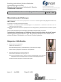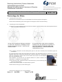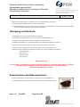
1
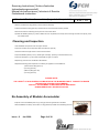
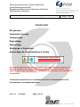
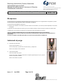
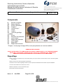
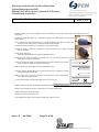
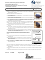
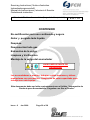
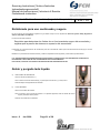
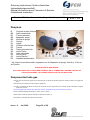
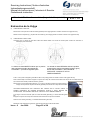
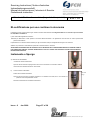
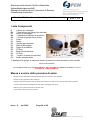
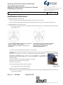
Servicing Instructions | Notice d’entretien
Instandsetzungsvorschrift
Manual de Instrucciones | Istruzioni di Servizio
Onderhouds instructies
Standard Bladder Accumulator (forged shell repairable)
• Servicing Instructions -
PVSI - 01
English
Standard Bladder Accumulator (forged shell repairable)
Pages 2 - 6
• Notice d’entretien -
French
Accumulateur à vessie standard (corps forgé)
Pages 8 – 13
• Instandsetzungsvorschrift - German
Blasenspeicher (geschmiedeter Körper, reparierbar)
Pages 14 – 19
• Manual de Instrucciones -
Spanish
Acumulador estándar de vejiga (de acero forjado y reparable)
Pages 20 – 25
• Istruzioni di Servizio -
Italian
Accumulatori a sacca standard (corpo forgiato riparabili)
Pages 26 - 31
• Onderhouds instructies -
Dutch
Standaard Bladder Accumulator (geforceerde lichaam)
Pages 32 - 36
Issue : 2
Jan 2006
Page 1 of 38
Registered Office: Works, Sandycroft Industrial Estate, Deeside, Flintshire CH5 2QP
Servicing Instructions | Notice d’entretien
Instandsetzungsvorschrift
Manual de Instrucciones | Istruzioni di Servizio
Onderhouds instructies
Standard Bladder Accumulator (forged shell repairable)
PVSI - 01
CONTENTS
Re-certification for continued safe use
Isolation & Draining
Parts List
Removal of Precharge
Removal of Bladder
Cleaning and Inspection
Re-Assembly of Bladder Accumulator
Important Safety Note
Gas loaded accumulators operate at high pressures and must always
be treated with caution.
You must ensure that you are competent to work with this equipment.
This document is to be read in conjunction with the booklet ‘Product
Information for Gas Loaded Accumulators’.
Issue : 2
Jan 2006
Page 2 of 38
Registered Office: Works, Sandycroft Industrial Estate, Deeside, Flintshire CH5 2QP
Servicing Instructions | Notice d’entretien
Instandsetzungsvorschrift
Manual de Instrucciones | Istruzioni di Servizio
Onderhouds instructies
Standard Bladder Accumulator (forged shell repairable)
PVSI - 01
Re-certification for continued safe use
In the UK most gas-loaded accumulators fall within the requirements of the Pressure Systems Safety Regulations 2000 No.128;
ISBN 0-11-085836-0.
Key points of this legislation include:
Requirements to determine the safe operating limits of the accumulator and record the fact that these are not exceeded by the system
pressure.
Preparation of a Written Scheme of Examination for accumulators used to store energy above certain limits.
Establishing a maintenance procedure and carrying out regular safety checks and examinations.
PROFESSIONAL ASSISTANCE IN MEETING THE REQUIREMENTS OF
THE REGULATIONS CAN BE PROVIDED BY FAWCETT CHRISTIE TRAINED
ACCUMULATOR RE-CERTIFICATION CENTRES AROUND THE COUNTRY.
PLEASE CONTACT OUR SALES OFFICE FOR DETAILS
Isolation & Draining
a)
WITH SAFETY BLOCK
Close Isolating Valve. ( 1 )
Open the Manual Relief/Drain Valve ( 2 ) until Pressure Gauge ( 3 ) registers zero.
Remove the Accumulator from Safety Block.
b)
WITH BLEED FACILITY
Isolate the Accumulator from the System.
Open Bleed facility, draining system fluid into a suitable receptacle, until all fluid and pressure have
been removed.
Remove the Accumulator from System Pipework.
Issue : 2
Jan 2006
Page 3 of 38
Registered Office: Works, Sandycroft Industrial Estate, Deeside, Flintshire CH5 2QP
Servicing Instructions | Notice d’entretien
Instandsetzungsvorschrift
Manual de Instrucciones | Istruzioni di Servizio
Onderhouds instructies
Standard Bladder Accumulator (forged shell repairable)
PVSI - 01
Parts list
B
B6
B7
B8
B9
C1
D1
D2
D3
D4
D5
E1
E2
E3
E4
Fluid Port Assembly
Flanged Washer
Locking Ring
Bleed Adaptor (if fitted) *
Bleed Valve (if fitted) *
Shell
Bladder
Gas Valve Assembly
Locknut
Protective Cap
‘O’ Ring
Anti Extrusion Ring
‘O’ Ring
Bonded Seal (if fitted) *
Back-up Ring
* The Bleed Adaptor, Valve and Bonded Seal are not fitted on all models.
SAFETY NOTE:
THE ACCUMULATOR CAN ONLY BE REMOVED FROM THE SYSTEM PIPEWORK ONCE THE
HYDRAULIC PRESSURE HAS BEEN REMOVED FROM THE ACCUMULATOR
Removal of Precharge
Remove Protective Cap (Item D4)(see PARTS LIST) from the Bladder Stem by unscrewing anti-clockwise.
Remove Sealing Cap from the Gas Valve Assembly (Item D2).
Connect Charging Set to the gas Valve Assembly, ensuring the spindle is fully wound out before connecting.
Screw the top knurled nut to depress the pin and open the valve core.
Release all the gas pressure by opening the Vent Valve. (1)
Disconnect the Charging Set from the Accumulator.
Issue : 2
Jan 2006
Page 4 of 38
Registered Office: Works, Sandycroft Industrial Estate, Deeside, Flintshire CH5 2QP
Servicing Instructions | Notice d’entretien
Instandsetzungsvorschrift
Manual de Instrucciones | Istruzioni di Servizio
Onderhouds instructies
Standard Bladder Accumulator (forged shell repairable)
PVSI - 01
Removal of bladder
a)
PREPARING THE GAS END
Unscrew the Gas Valve Assembly (Item D2) from the Bladder Stem by turning anti-clockwise.
Remove the Locknut (2) and Nameplate (3) from the Bladder Stem by turning the Locknut anti-clockwise.
b)
PREPARING THE FLUID END
Check that the oil side poppet valve has opened under force from its spring (Note: An Endoscope may be required to confirm
this).
Poppet valve OPEN indicating that gas / oil
pressure has been relieved from the accumulator –
proceed to the next step.
Poppet valve CLOSED indicating the possible
presence of trapped pressure (oil or gas) within the
accumulator. DO NOT PROCEED FURTHER –
CONSULT FCH IMMEDIATELY.
If fitted, remove the Bleed Adaptor (Item B8 with B9 if attached) by unscrewing anti-clockwise.
The disassembly requires the oil port to be pushed back inside the shell before it can be disengaged from the anti-extrusion ring
and withdrawn.
Unscrew the Locking Ring (Item B7) 2 or 3 turns anti-clockwise and then push the Fluid Port Body
(Item B) into the Accumulator Shell
ANY RESISTANCE FROM THE OIL PORT MAY INDICATE THE PRESENCE OF TRAPPED
PRESSURE WITHIN THE ACCUMULATOR THEREFORE DO NOT PROCEED FURTHER –
CONSULT FCH IMMEDIATELY.
if it is safe to proceed then remove the Locking Ring (Item B7) and the Flanged Washer (Item B6)
Push the Fluid Port Assembly (Item B) into the Accumulator Shell.
Remove the ‘O’ Ring (Item E2) and the Backup Ring (Item E4)
Issue : 2
Jan 2006
Page 5 of 38
Registered Office: Works, Sandycroft Industrial Estate, Deeside, Flintshire CH5 2QP
Servicing Instructions | Notice d’entretien
Instandsetzungsvorschrift
Manual de Instrucciones | Istruzioni di Servizio
Onderhouds instructies
Standard Bladder Accumulator (forged shell repairable)
PVSI - 01
Slide the Anti-Extrusion Ring (Item E1) off the Fluid Port Assembly
Fold the Anti-Extrusion Ring (Item E1) until removal from the Accumulator Shell is possible.
Remove the Fluid Port Assembly (Item B) from the Accumulator Shell.
Squeeze the Bladder (Item D1) by hand to deflate as much as possible, then slowly remove through the Fluid Port opening in the
Accumulator Shell.
Cleaning and Inspection
Clean all Metallic Components with an Organic Solvent.
Inspect the condition of all components within the Fluid Port. (Item B)
Check the Fluid Port Poppet Valve to ensure free movement.
Inspect the Bladder (Item D1) for any visible signs of damage. (Cracking or Surface Abrasion etc.)
Inspect the Shell (Item C1), both Inside and Outside for signs of corrosion.
Replace any parts found or considered to be defective.
Replace the following parts irrespective of condition (as supplied in a FCH bladder kit:
1) Anti-Extrusion Ring (Item E1)
2) ‘O’ Ring (Item E2)
3) Back Up Ring (Item E4)
4) ‘O’ Ring (Item D5)
PLEASE NOTE:
THE ‘HEART’ OF A BLADDER ACCUMULATOR IS THE BLADDER ITSELF. FAWCETT CHRISTIE
HYDRAULICS STRONGLY RECOMMEND
THAT ALL ELASTOMERIC COMPONENTS ARE REPLACED
DURING SERVICING / RE-CERTIFICATION.
Re-Assembly of Bladder Accumulator
Expel all air from the Bladder (Item D1) by rolling up from the opposite end to the Stem.
Whilst the Bladder is rolled up, fit the Stem ‘O’ Ring (Item D5) and Gas Valve Assembly (Item D2).
Issue : 2
Jan 2006
Page 6 of 38
Registered Office: Works, Sandycroft Industrial Estate, Deeside, Flintshire CH5 2QP
Servicing Instructions | Notice d’entretien
Instandsetzungsvorschrift
Manual de Instrucciones | Istruzioni di Servizio
Onderhouds instructies
Standard Bladder Accumulator (forged shell repairable)
PVSI - 01
Unroll the Bladder (Item D1) and lubricate both the Bladder and the Inside of the Shell (Item C1) with System Fluid.
Attach Pull Rod to Gas Valve Assembly. (Item D2)
Feed Pull Rod through Fluid End Opening and out of Gas End Opening.
Begin feeding and pulling Bladder into the Shell using the Pull Rod. Do not twist the Bladder during
this operation.
Pull the Bladder Stem through the Gas End Opening and fit the Nameplate and Locknut (Item D3) by
turning clockwise, again ensuring the bladder stem does not turn.
Insert the Fluid Port Assembly (Item B) and Anti-Extrusion Ring (Item E1) into the Shell Fluid End
Opening.
Slide the Anti-Extrusion Ring over the Fluid Port Body and then pull the Fluid Port through the Shell
Fluid End Opening.
Remove Pull Rod from the Gas Valve. (Item D2)
Tighten Gas Valve to a MAXIMUM Torque of 25 Nm
Fit Charging Set onto Gas Valve (Item D2) and Inflate the Bladder with a low Pre-Charge of 2 Bar to
seat the Fluid Port Assembly and Anti-Extrusion Ring.
Using a Rubber or Nylon Hammer tap the Fluid Port Assembly at various angles to ensure
that the Fluid Port is correctly seated within the shell.
Fit ‘O’ Ring (Item E2) and PTFE Back Up Ring (Item E4) onto the Fluid port.
Assembly Body (Item B) and position inside the gap left between the Shell and the Fluid
Port Body.
Slide the Flanged Washer (Item B6) over the Fluid Port Body until it comes into contact
with the PTFE Back Up Ring. (Item E4)
Fit Locking ring (Item B7) onto Fluid Port Body and screw clockwise until hand tight and
then tighten with the correct spanner.
Replace Bleed Valve and Bleed Adaptor (Items B8 & B9 if fitted) into Fluid port Assembly
(Item B) by screwing clockwise and tighten with spanner.
Correct fitting of Spiral Back up Ring E4
Precharge Bladder to predetermined pressure using dry Nitrogen Gas only.
Remove the Charging Set and refit the Dust Cap to the Gas Valve. (Item D2)
Check Locking Ring (Item B7) and Locknut (Item D3) for tightness.
The Re-Assembly is now complete and the Accumulator is ready to be returned to service.
Issue : 2
Jan 2006
Page 7 of 38
Registered Office: Works, Sandycroft Industrial Estate, Deeside, Flintshire CH5 2QP
Servicing Instructions | Notice d’entretien
Instandsetzungsvorschrift
Manual de Instrucciones | Istruzioni di Servizio
Onderhouds instructies
Standard Bladder Accumulator (forged shell repairable)
PVSI - 01
SOMMAIRE
Ré-épreuve
Isolement et purge
Composants
Dégonflage
Démontage
Nettoyage et Inspection
Remontage de l’accumulateur à vessie
Remarque importante
concernant la sécurité
Les accumulateurs chargés au gaz fonctionnent à haute pression et
doivent toujours être manipulés avec précaution. Vous devez vous
assurer que vous possédez les compétences requises pour manipuler
ce matériel.
Ce document doit être lu en complément du livret ‘Informations sur les
accumulateurs hydropneumatiques’.
Issue : 2
Jan 2006
Page 8 of 38
Registered Office: Works, Sandycroft Industrial Estate, Deeside, Flintshire CH5 2QP
Servicing Instructions | Notice d’entretien
Instandsetzungsvorschrift
Manual de Instrucciones | Istruzioni di Servizio
Onderhouds instructies
Standard Bladder Accumulator (forged shell repairable)
PVSI - 01
Ré-épreuve
Au Royaume-Uni les accumulateurs hydropneumatiques sont soumis aux exigences de la réglementation des appareils à pression :
Pressure Systems Safety Regulations 2000 No.128; ISBN 0-11-085836-0.
Les points clés de cette législation comprennent :
Les exigences pour déterminer les conditions de service limites de l’accumulateur, qui ne doivent pas être dépassées par la pression
du système.
La préparation d’une demande écrite d’examen pour les accumulateurs utilisés en réserve d’énergie au dessus de certaines limites.
L’établissement d’une procédure de maintenance, de vérifications de sécurité régulières et d’examens.
FAWCETT CHRISTIE POSSEDE DANS TOUT LE PAYS DES CENTRES QUALIFIES POUR LA RE-EPREUVE
D’ACCUMULATEURS ET PEUT FOURNIR UNE ASSISTANCE PROFESSIONNELLE REPONDANT AUX EXIGENCES DE LA
LEGISLATION.
POUR DE PLUS AMPLES INFORMATIONS, MERCI DE CONTACTER NOTRE SERVICE COMMERCIAL.
Isolement et purge
a)
AVEC BLOC DE SECURITE
Fermer la valve d’isolement. ( 1 )
Ouvrir la vis de purge ( 2 ) jusqu’à ce que le manomètre ( 3 ) indique zéro.
Retirer l’accumulateur du bloc d’isolement.
b)
AVEC VIS DE PURGE
Isoler l’accumulateur du système
Ouvrir la vis de purge ; récupérer le fluide dans un récipient approprié jusqu’à ce qu’il n’y ait plus
de fluide ni de pression résiduelle.
Retirer l’accumulateur du système.
Issue : 2
Jan 2006
Page 9 of 38
Registered Office: Works, Sandycroft Industrial Estate, Deeside, Flintshire CH5 2QP
Servicing Instructions | Notice d’entretien
Instandsetzungsvorschrift
Manual de Instrucciones | Istruzioni di Servizio
Onderhouds instructies
Standard Bladder Accumulator (forged shell repairable)
PVSI - 01
Composants
B
Bouche complète
B6
Bague épaulée
B7
Ecrou à encoches
B8
Purgeur *
B9
Vis de purge *
C1
Corps
D1
Vessie
D2
Valve de gonflage
complète
D3
Ecrou
D4
Bouchon de protection
D5
Joint torique
E1
Bague caoutchoutée
E2
Joint torique
E3
Bague BS *
E4
Bague anti-extrusion
* Purgeur, vis de purge et bague BS ne sont pas présents sur tous les modèles.
REMARQUE DE SECURITE:
AVANT DE DEPOSER L’ACCUMULATEUR DU CIRCUIT HYDRAULIQUE, IL FAUT IMPERATIVEMENT
RELACHER LA PRESSION HYDRAULIQUE DU CIRCUIT ET S’ASSURER DE L’ABSENCE DE
PRESSION HYDRAULIQUE RESIDUELLE AU NIVEAU DE L’ACCUMULATEUR.
Dégonflage
Retirer le bouchon de protection (D4) (voir liste des pièces) du corps de valve en tournant dans le sens inverse des aiguilles
d’une montre.
Retirer le bouchon de la valve de gonflage complète (D2)
Connecter le VG à la valve de gonflage. S’assurer que la vis pointeau est dévissée avant de mettre en place l’adaptateur.
Tourner le volant à lobes du VG afin d’ouvrir la valve.
Relâcher la pression en ouvrant le robinet de purge.
Déconnecter le VG de l’accumulateur.
Issue : 2
Jan 2006
Page 10 of 38
Registered Office: Works, Sandycroft Industrial Estate, Deeside, Flintshire CH5 2QP
Servicing Instructions | Notice d’entretien
Instandsetzungsvorschrift
Manual de Instrucciones | Istruzioni di Servizio
Onderhouds instructies
Standard Bladder Accumulator (forged shell repairable)
PVSI - 01
Démontage de la vessie
a)
OPERATION COTE GAZ
Retirer la valve de gonflage (D2) du corps de valve en dévissant dans le sens inverse des aiguilles d’une montre
Retirer l’écrou (D3) et la plaque firme du corps de valve en dévissant dans le sens inverse des aiguilles d’une montre
b)
OPERATION COTE FLUIDE
Vérifier que la soupape est ouverte par l’action du ressort (l’utilisation d’un endoscope peut être nécessaire)
Soupape ouverte indiquant qu’il n’y a pas de
pression résiduelle (gaz ou fluide). Passer à
l’étape suivante.
Soupape fermée indiquant la présence éventuelle
de pression résiduelle (gaz ou fluide). NE PAS
CONTINUER – CONTACTER IMMEDIATEMENT
FCH.
Le cas échéant, retirer la vis de purge (B8 et B9) en dévissant dans le sens inverse des aiguilles d’une montre.
Le démontage nécessite que le corps de bouche soit poussé à l’intérieur du corps d’accumulateur avant de pouvoir le séparer de
la bague en deux parties et de le retirer.
Dévisser l’écrou à encoches (B7) en effectuant 2 ou 3 tours dans le sens inverse des aiguilles d’une
montre.
Pousser le corps de bouche (B) à l’intérieur du corps de l’accumulateur.
LA MOINDRE RESISTANCE DU CORPS DE BOUCHE PEUT SIGNIFIER LA PRESENCE DE
PRESSION RESIDUELLE A L’INTERIEUR DE L’ACCUMULATEUR. NE PAS FORCER.
CONTACTER IMMEDIATEMENT FCH.
Si le corps de bouche peut être poussé sans difficultés, retirer complètement l’écrou à encoches
(B7) et la bague épaulée (B6).
Pousser complètement la bouche (B) dans le corps de l’accumulateur.
Retirer le joint torique (E2) et la bague anti extrusion (E4).
Issue : 2
Jan 2006
Page 11 of 38
Registered Office: Works, Sandycroft Industrial Estate, Deeside, Flintshire CH5 2QP
Servicing Instructions | Notice d’entretien
Instandsetzungsvorschrift
Manual de Instrucciones | Istruzioni di Servizio
Onderhouds instructies
Standard Bladder Accumulator (forged shell repairable)
PVSI - 01
Dégager la bague en deux parties (E1) de la bouche.
Replier avec précaution la bague en 2 parties (E1) de manière à la sortir du corps de l’accumulateur.
Extraire la bouche (B) du corps de l’accumulateur.
Compresser la vessie (D1) et l’extraire à la main par l’ouverture côté bouche, en veillant à ne pas l’endommager.
Nettoyage et Inspection
Nettoyer soigneusement toutes les pièces métalliques avec un solvant organique.
Vérifier visuellement l’état de toutes les pièces à l’intérieur de la bouche (B).
Contrôler en appuyant sur la tête de la soupape que celle-ci coulisse normalement.
Vérifier que la vessie (D1) ne présente aucun défaut d’aspect (craquelures, abrasion,…)
Vérifier qu’il n’y ait aucune trace de corrosion à l’intérieur et à l’extérieur du corps de l’accumulateur (C1).
Remplacer les pièces jugées défectueuses.
Remplacer les pièces suivantes (fournies dans le kit de rechange FCH) , quel que soit leur état :
1) Bague en 2 parties (E1)
2) Joint torique (E2)
3) Bague anti extrusion (E4)
4) Joint torique (D5)
REMARQUE:
LE ‘CŒUR’ D’UN ACCUMULATEUR EST LA VESSIE. FCH RECOMMANDE DE REMPLACER TOUTES
LES PIECES EN ELASTOMERE APRES CHAQUE REVISION ET RE-CERTIFICATION.
Remontage d’un accumulateur
Evacuer l’air de la vessie en la comprimant, de l’extrémité vers le corps de valve.
En maintenant la vessie enroulée, mettre le joint torique (D5) et la valve de gonflage (D2).
Issue : 2
Jan 2006
Page 12 of 38
Registered Office: Works, Sandycroft Industrial Estate, Deeside, Flintshire CH5 2QP
Servicing Instructions | Notice d’entretien
Instandsetzungsvorschrift
Manual de Instrucciones | Istruzioni di Servizio
Onderhouds instructies
Standard Bladder Accumulator (forged shell repairable)
PVSI - 01
Dérouler la vessie (D1). Lubrifier l’intérieur du corps d’accumulateur (C1) ansi que la vessie avec le fluide utilisé dans le circuit
hydraulique.
Introduire la vessie côté bouche, et la positionner à l’aide du tire-vessie. Veiller à ne pas plier ou
vriller la vessie.
Tirer le corps de valve par l’ouverture coté gaz ; remonter la plaque firme et l’écrou de fixation (D3).
S’assurer que le corps de valve ne tourne pas pendant cette opération.
Introduire la bouche et la bague en 2 parties dans le corps d’accumulateur.
Remettre en position la bague en 2 parties sur le corps de bouche. Tirer le corps de bouche à
travers l’ouverture.
Enlever le tire-vessie. (D2)
Serrer la valve de gonflage à un couple MAXIMUM de 25 N.m.
Installer le VG et gonfler la vessie à une pression de 2 bar, ceci afin de positionner la bouche
assemblée et la bague caoutchoutée.
Assurer le centrage des pièces en frappant légèrement le corps de bouche sous plusieurs
angles à l’aide d’un maillet en caoutchouc ou en Nylon.
Mettre en place le joint torique (E2) et la bague anti-extrusion (E4).
Positionner la bague épaulée (B6) sur le corps de bouche jusqu’à ce qu’elle soit en contact
avec la bague anti-extrusion (E4)
Mettre en place l’écrou à encoches (B7) sur le corps de bouche et serer manuellement.
Serrer ensuite à l’aide d’une clef.
Le cas échéant remettre le purgeur (B8 & B9). Serrer à l’aide d’une clef.
Positionnement correct de la bague anti-extrusion E4
Gonfler la vessie à la pression de gonflage recommandée. Utiliser uniquement de l’azote pur.
Retirer le VG et remettre le bouchon de protection sur la valve de gonflage (D2)
Vérifier le serrage des écrous (B7 et D3).
Remettre le bouchon de protection (D4).
Le remontage est terminé et l’accumulateur est prêt à être remis en service.
Issue : 2
Jan 2006
Page 13 of 38
Registered Office: Works, Sandycroft Industrial Estate, Deeside, Flintshire CH5 2QP
Servicing Instructions | Notice d’entretien
Instandsetzungsvorschrift
Manual de Instrucciones | Istruzioni di Servizio
Onderhouds instructies
Standard Bladder Accumulator (forged shell repairable)
PVSI - 01
Inhalt
Wiederkehrende Prüfungen
Absperren und Entlasten des Speichers
Teileliste
Ablassen des Vorfülldruckes
Demontage der Blase
Reinigung und Kontrolle
Zusammenbau des Blasenspeichers
Wichtige Sicherheitshinweise
Hydrospeicher arbeiten bei hohem Druck und müssen daher
immer mit Vorsicht behandelt werden. Der Betreiber ist für
den sachgemäßen Umgang mit Hydrospeichern
verantwortlich.
Die Vorschriften dieses Dokuments gelten in Verbindung mit der Broschüre
‘Produktinformation zu Hydrospeichern“.
Issue : 2
Jan 2006
Page 14 of 38
Registered Office: Works, Sandycroft Industrial Estate, Deeside, Flintshire CH5 2QP
Servicing Instructions | Notice d’entretien
Instandsetzungsvorschrift
Manual de Instrucciones | Istruzioni di Servizio
Onderhouds instructies
Standard Bladder Accumulator (forged shell repairable)
PVSI - 01
Wiederkehrende Prüfungen
In Großbritannien gelten für die meisten Hydrospeicher die Vorschriften der Pressure Systems Safety Regulations 2000 No.128;
ISBN 0-11-085836-0.
Die wichtigsten Vorschriften dieses Gesetzes beinhalten:
Anforderungen zur Bestimmung sicherer Betriebsbedingungen des Hydrospeichers zur Maßnahmen damit diese nicht vom
Systemdruck überschritten werden.
Festlegung eines schriftlichen Prüfplans für Hydrospeicher die zur Energiespeicherung oberhalb bestimmter Grenzwerte eingesetzt
werden.
Einführung eines Wartungsplans sowie die Ausweisung regelmäßiger Sicherheitskontrollen und Prüfungen.
Professionelle Unterstützung zur Einhaltung dieser Vorschriften bieten die durch Fawcett
Christie Hydraulics geschulten Prüf- und Servicecenter überall im Land. Details hierzu
erhalten Sie beim Vertriebsbüro von Fawcett Christie Hydraulics.
Absperren & Entlasten
a)
Mittels Sicherheits- und Absperrblock
Schließen des Absperrhahns. ( 1 )
Öffnen des Entlastungsventils ( 2 ) bis der Manometer ( 3 ) keinen Druck mehr anzeigt.
Entfernen Sie den Hydrospeicher vom Sicherheits- und Absperrblock.
b)
Mittels der Entlastungseinrichtung des Hydrospeichers
Sperren Sie den Hydrospeicher vom hydr. System ab.
Öffnen Sie die Entlastungsvorrichtung, lassen Sie solange Hydraulikflüssigkeit in einen geeigneten
Auffangbehälter ab bis die Flüssigkeit entfernt und der Druck vollständig abgebaut wurde.
Deinstallieren Sie den Hydrospeicher aus dem Rohrleitungsnetz.
Issue : 2
Jan 2006
Page 15 of 38
Registered Office: Works, Sandycroft Industrial Estate, Deeside, Flintshire CH5 2QP
Servicing Instructions | Notice d’entretien
Instandsetzungsvorschrift
Manual de Instrucciones | Istruzioni di Servizio
Onderhouds instructies
Standard Bladder Accumulator (forged shell repairable)
PVSI - 01
Teileliste
B
Flüssigkeitsventil
B6
Distanzring
B7
Nutmutter
B8&B9Entlüftungsventil
(sofern verwendet) *
C1
Speicherkörper
D1
Blase
D2
Gasfüllventil komplett
D3
Haltemutter
D4
Schutzkappe
D5
‘O’ Ring
E1
geteilter Ring
E2
‘O’ Ring
E3
USIT-Ring
(sofern verwendet) *
E4
Stützring
* Entlüftungsventil und USIT-Ring werden nicht bei allen Modellen verwendet.
Sicherheitshinweis:
Der Hydrospeicher darf erst aus den System ausgebaut werden, nachdem der Hydraulikdruck
vollständig aus dem Speicher abgelassen wurde!
Ablassen des Vorfülldruckes
Entfernen der Schutzkappe („D4“)(siehe Teileliste) Gasventilkörper durch abschrauben gegen den Uhrzeigersinn.
Entfernen der Dichtkappe des Gasfüllventils („D2“).
Verbinden Sie das Füll- und Prüfgerät mit dem Gasventil. Stellen Sie vorher sicher, dass die Spindel des Füllgerätes in
Nullstellung steht.
Öffnen Sie gas Gasfüllventil mittels der Spindel durch Drehen des großen Handgriffs.
Lassen Sie das Gas vollständig ab durch Öffnen des Entlastungsventils. (1)
Entfernen Sie das Füll- und Prüfgerät vom Speicher.
Issue : 2
Jan 2006
Page 16 of 38
Registered Office: Works, Sandycroft Industrial Estate, Deeside, Flintshire CH5 2QP
Servicing Instructions | Notice d’entretien
Instandsetzungsvorschrift
Manual de Instrucciones | Istruzioni di Servizio
Onderhouds instructies
Standard Bladder Accumulator (forged shell repairable)
PVSI - 01
Demontage der Blase
a)
Vorbereitungen auf der Gasseite
Demontieren Sie das Gasfüllventil (“D2”) vom Gasventilkörper durch Drehen gegen den Uhrzeigersinn.
Entfernen Sie die Haltemutter (2) durch Drehen gegen den Uhrzeigersinn, danach das Firmenschild (3).
b)
Vorbereitungen auf der Flüssigkeitsseite
Kontrollieren Sie ob das Flüssigkeitsventil durch die Kraft der Ventilfeder in geöffneter Stellung steht. (Notiz: Möglicherweise kann
hierzu ein Endoskop notwendig sein.).
Ist das Ventil in geöffneter Stellung so zeigt dies
an, dass Gas- und Öldruck vollständig aus dem
Speicher abgelassen wurden – weiter mit dem
nächsten Schritt.
Ein geschlossenes Ventil weist auf möglichen
Restdruck (Öl- oder Gasdruck) im Speicher hin.
WEITERE ARBEITEN AM SPEICHER SIND
NICHT GESTETTET – KONTAKTIEREN SIE
UNVERZÜGLICH FCH!
Sofern vorhanden, demontieren Sie das Entlüftungsventil („B8“ mit „B9“ sofern verwendet) durch herausdrehen gegen den
Uhrzeigersinn.
Die weitere Demontage erfordert das Hineinschieben des Ölventils in den Speicherkörper bevor der geteilte Ring vom Ölventil
abgestreift werden kann. Lösen Sie die Nutmutter (“B7“), drehen Sie diese 2 bis 3 Umdrehungen
gegen den Uhrzeigersinn. Danach lockern Sie das Ölventil durch Drücken des Ölventilkörpers
(„B“) in den Speicherkörper hinein.
Jeder Widerstand des Ölventils kann auf möglichen Restdruck im Speicher hinweisen. Nicht
weiterarbeiten – Kontaktieren Sie unverzüglich FCH!
Ist das Ölventil jetzt locker, besteht keine Gefahr. Die Nutmutter („B7“) und der Distanzring („B6“)
können nun entfernt werden.
Schieben Sie das Ölventil komplett in den Speicherkörper („B“)hinein.
Entfernen Sie den O-Ring („E2“) und den Stützring („E4“).
Streifen Sie den geteilten Ring („E1“) vom Ölventilkörper.
Issue : 2
Jan 2006
Page 17 of 38
Registered Office: Works, Sandycroft Industrial Estate, Deeside, Flintshire CH5 2QP
Servicing Instructions | Notice d’entretien
Instandsetzungsvorschrift
Manual de Instrucciones | Istruzioni di Servizio
Onderhouds instructies
Standard Bladder Accumulator (forged shell repairable)
PVSI - 01
Falten Sie den geteilten Ring („E1“) während Sie ihn aus dem Speicherkörper herausziehen..
Entnehmen Sie das Flüssigkeitsventil („B“) aus dem Speicherkörper.
Drücken Sie die Blase („D1“) mit der Hand zusammen um möglichst viel Gas entweichen zu lassen. Danach ziehen Sie die Blase
durch die flüssigkeitsseitige Öffnung des Speicherkörpers heraus.
Reinigung und Kontrolle
Alle Metallteile sind mit einem biologisch abbaubaren Lösemittel.
Kontrollieren Sie den Zustand aller Teile, auch im Inneren des Flüssigkeitsventils („B“).
Kontrollieren Sie die einwandfreie Funktion des Ventiltellers im Flüssigkeitsventil..
Kontrollieren Sie die Blase („D1“) auf sichtbare Anzeichen einer Beschädigung (Risse oder Abrieb etc.)
Kontrollieren Sie den Speicherkörper („C1“) innen und außen auf Anzeichen von Korrosion.
Ersetzen Sie alle beschädigten Teile sowie Teile deren Zustand nicht einwandfrei sein könnte.
Folgende Teile sind unbeachtet ihres Zustandes zu ersetzen (wie von FCH im Reparatursatz geliefert):
1) geteilter Ring („E1“)
2) O- Ring (“E2”)
3) Stützring (“E4”)
4) O- Ring (”D5”)
Bitte beachten Sie:
Für die Funktion eines Blasenspeichers ist die Blase selbst von entscheidender Bedeutung. Fawcett
Christie Hydraulics empfiehlt daher, alle Elastomerteile bei einer Überprüfung /
Wiederholungsprüfung zu ersetzen.
Zusammenbau des Blasenspeichers
Entlüften Sie die Blase (“D1”) durch Rollen vom unteren Ende zum Gasventilkörper hin.
Im zusammengerollten Zustand montieren Sie den O-Ring („D5“) uns das Gasfüllventil („D2“).
Issue : 2
Jan 2006
Page 18 of 38
Registered Office: Works, Sandycroft Industrial Estate, Deeside, Flintshire CH5 2QP
Servicing Instructions | Notice d’entretien
Instandsetzungsvorschrift
Manual de Instrucciones | Istruzioni di Servizio
Onderhouds instructies
Standard Bladder Accumulator (forged shell repairable)
PVSI - 01
Entrollen Sie nun die Blase („D1“) wieder. Die Blase und das Innere des Speicherkörpers (C1“) sind nun mit reichlich
Betriebsflüssigkeit zu schmieren.
Verbinden Sie die Zugstange mit dem Gasfüllventil („D2“).
Führen Sie die Zugstange von der Flüssigkeitsseite her in den Speicherkörper ein und durch die
gasseitige Öffnung heraus.
Führen Sie nun die Blase in den Speicherkörper ein, Ziehen Sie hierzu leicht an der Zugstange. Die
Blase darf hierbei nicht gedreht/verdreht werden.
Ziehen Sie den Gasventilkörper durch die gasseitige Öffnung des Speicherkörpers, befestigen Sie
das Firmenschild und montieren Sie die Haltemutter durch Drehen im Uhrzeigersinn auf dem Gasventilkörper. Der
Gasventilkörper darf sich hierbei nicht verdrehen!
Führen Sie nun das Flüssigkeitsventil („B“) und den geteilten Ring („E1“) in den Speicherkörper ein.
Schieben Sie nun den geteilten Ring über das Flüssigkeitsventil. Ziehen Sie nun das
Flüssigkeitsventil durch die Speicherkörperöffnung nach außen.
Entfernen Sie die Zugstange vom Gasfüllventil („D2) und ziehen Sie das Gasfüllventil mit maximal
25Nm fest.
Setzen Sie das Füll- und Prüfgerät auf das Gasventil („D2“) und befüllen Sie langsam die Blase mit
einem Druck von 2 bar um das Flüssigkeitsventil mit dem geteilten Ring in den Führungen des
Speicherkörpers zu fixieren.
Klopfen Sie hierbei mittels einem Gummi- oder Kunststoffhammers leicht von verschiedenen Seiten gegen das Flüssigkeitsventil.
Damit wird erreicht, dass Flüssigkeitsventil und geteilter Ring richtig in den dafür
vorgesehenen Sitz im Speicherkörper hineinrutschen.
Montieren Sie O-Ring (“E2”) und Stützring („E4“) auf das Flüssigkeitsventil. Diese Teile
werden in den verbleibenden Spalt zwischen Flüssigkeitsventil und Speicherkörper
montiert.
Führen Sie den Distanzring über den Körper des Flüssigkeitsventils bis er Kontakt zum
Stützring(„E4“) hat.
Sciben Sie die Nutmutter (“B7”) über das Flüssigkeitsventil und schrauben Sie diese durch
Drehen im Uhrzeigersinn mir der Hand fest. Danach ziehen Sie die Nutmutter mittels
des Hakenschlüssels nach.
Montieren Sie nun die Teile des Entlüftungsventils („B8 & B9“) in das Flüssigkeitsventil
durch Einschrauben im Uhrzeigersinn. Ziehen Sie die Teile mittels eines
Schraubenschlüssels fest..
Korrekter Einbau eines
spiralförmigen Stützringes E4
Füllen Sie nun die Blase auf den notwendigen Gasvorspanndruck. Verwenden Sie hierzu nur trockenen Stickstoff!
Entfernen Sie die Füll- und Prüfvorrichtung
Blasenspeichers.
und montieren Sie nun die Schutzkappe („D2“) wieder auf die Gasseite des
Kontrollieren Sie die Haltemutter der Blase (“D3”) und die Nutmutter (“B7”) auf festen Sitz und ziehen Sie diese falls notwendig
nach!.
Der Zusammenbau des Blasenspeichers ist nun beendet. Der Speicher kann nun wieder ins Hydrauliksystem eingebaut werden.
Issue : 2
Jan 2006
Page 19 of 38
Registered Office: Works, Sandycroft Industrial Estate, Deeside, Flintshire CH5 2QP
Servicing Instructions | Notice d’entretien
Instandsetzungsvorschrift
Manual de Instrucciones | Istruzioni di Servizio
Onderhouds instructies
Standard Bladder Accumulator (forged shell repairable)
PVSI - 01
CONTENIDO
Re-certificación para uso continuado y seguro
Aislar y purgado lado líquido
Despiece
Despresurizar lado gas
Extracción de la vejiga
Limpieza y Verificación
Montaje de la vejiga del acumulador
AVISO IMPORTANTE DE
SEGURIDAD
Los acumuladores a presión trabajan a altas presiones y deben
manipularse con precaución. Asegúrese de estar capacitado para
trabajar con este equipo.
Este documento debe ser leído conjuntamente con el folleto “Información de
Producto para Acumuladores Cargados con Gas a Presión”
Issue : 2
Jan 2006
Page 20 of 38
Registered Office: Works, Sandycroft Industrial Estate, Deeside, Flintshire CH5 2QP
Servicing Instructions | Notice d’entretien
Instandsetzungsvorschrift
Manual de Instrucciones | Istruzioni di Servizio
Onderhouds instructies
Standard Bladder Accumulator (forged shell repairable)
PVSI - 01
Retimbrado para uso continuado y seguro
En UK la mayoría de acumuladores cargados con gas deben cumplir con los requisitos de Pressure Systems Safety Regulations
2000 No.128; ISBN 0-11-085836-0.
Puntos clave de esta normativa:
Requisitos para determinar los límites de un funcionamiento seguro del acumulador y
registrar que la presión de sistema no supera la del acumulador.
Preparación de un Esquema Escrito de Certificación para los acumuladores usados para el almacenamiento de energía por encima
de ciertos límites.
Establecer un procedimiento de mantenimiento y realizar comprobaciones de seguridad y verrificaciones periodicamente.
LOS CENTROS EXPERTOS EN RECERTIFICACION DE FAWCETT CHRISTIE EN EL PAIS PUEDEN DAR LA ASISTENCIA
PROFESIONAL PARA CUMPLIR CON LAS EXIGENCIAS DE LOS REGLAMENTOS
POR FAVOR, CONTACTE CON NUESTRA OFICINA DE VENTAS PARA MAS DETALLES.
Aislair y purgado lado líquido
a)
CON BLOQUE DE SEGURIDAD
Cerrar la válvula de aislamiento ( 1 )
Abrir la válvula manual de alivio/drenaje ( 2 ) hasta que el manómetro ( 3 ) marque cero.
Quitar el Bloque de Seguridad del Acumulador.
b)
CON PURGADOR
Aislar el Acumulador del sistema.
Abrir el purgador, vacie el aceite del sistema a un depósito apropiado, hasta el vaciado de todo el
líquido y eliminado toda la presión.
Quitar el Acumulador de la Instalación.
Issue : 2
Jan 2006
Page 21 of 38
Registered Office: Works, Sandycroft Industrial Estate, Deeside, Flintshire CH5 2QP
Servicing Instructions | Notice d’entretien
Instandsetzungsvorschrift
Manual de Instrucciones | Istruzioni di Servizio
Onderhouds instructies
Standard Bladder Accumulator (forged shell repairable)
PVSI - 01
Despiece
B
B6
B7
B8
B9
C1
D1
D2
D3
D4
D5
E1
E2
E3
E4
Conjunto cuerpo Válvula
Anillo escalonado
Tuerca ranurada
Adaptador purga *
Válvula de purga *
Cuerpo
Vejiga
Conjunto Válvula Gas
Tuerca
Tapón de protección
Junta Tórica
Anillo articulado
Junta Tórica
Junta Fijación *
Arandela antiextrusión
* No todos los modelos están equipados con el Adaptador de purga, Válvula y la Junta
de Fijación.
ADVERTENCIA DE SEGURIDAD:
EL ACUMULADOR SÓLO PUEDE SER RETIRADO DE LA TUBERÍA DEL SISTEMA UNA VEZ SE
HAYA DESCARGADO LA PRESIÓN HIDRÁULICA DEL ACUMULADOR
Despresurizar lado gas
Quitar el tapón de protección (pieza D4) (ver Despiece) de la válvula de hinchado girando en sentido contrario a las agujas del
reloj.
Quitar el tapón del conjunto de la válvula de gas (pieza D2).
Conectar el Verificador Hinchador al Conjunto de la Válvula de Gas, asegurando que el vástago quede enteramente acoplado
antes de la conexión.
Connect Charging Set to the gas Valve Assembly,.ensuring the spindle is fully wound out before connecting.
Roscar la cabeza Grafilada para aflojar el macho y abrir la válvula.
Liberar toda la presión del lado gas abriendo la válvula de hinchado. (1)
Desconectar el Verificador Hinchador del Acumulador.
Issue : 2
Jan 2006
Page 22 of 38
Registered Office: Works, Sandycroft Industrial Estate, Deeside, Flintshire CH5 2QP
Servicing Instructions | Notice d’entretien
Instandsetzungsvorschrift
Manual de Instrucciones | Istruzioni di Servizio
Onderhouds instructies
Standard Bladder Accumulator (forged shell repairable)
PVSI - 01
Extracción de la Vejiga
a)
PREPARACIÓN LADO GAS:
Desenroscar el Conjunto de la Válvula de Gas (pieza D2) de la vejiga girando en sentido contrario a las agujas del reloj.
Retirar la tuerca de fijación (2) y la placa del Acumulador (3) de la vejiga girando en sentido contrario a las agujas del reloj.
b)
PREPARACIÓN LADO FLUIDO:
Comprobar que la válvula de seta lado aceite esta abierta debido a la fuerza del muelle (Nota: Puede ser necesario un
endescopio para confirmarlo)
La válvula de seta ABIERTA indica que la presión
lado gas/aceite ha sido descargada del
acumulador – proceda al siguiente paso.
La válvula de Seta CERRADA indica la posible
presencia de presión bloqueada (aceite o agua)
dentro del acumulador. NO CONTINUE
ADELANTE -CONSULTE A FCH
INMEDIATAMENTE.
Si es el caso, quitar el Purgador (pieza B8 con B9 si van juntas) girando en sentido contrario a las agujas del reloj.
Para el desmontaje es necesario empujar el conjunto del cuerpo de la válvula hacía dentro del cuerpo del acumulador antes de
que el anillo anti-extrusión pueda ser liberado y quitado.
Desenroscar la Tuerca Ranurada (pieza B7), 2 o 3 giros en sentido contrario a las agujas del reloj y
empujar el Conjunto del cuerpo de la Válvula (pieza B) hacía dentro del cuerpo del acumulador.
CUALQUIER RESISTENCIA DEL CONJUNTO DEL CUERPO DE LA VÁLVULA INDICA LA
POSIBLE PRESENCIA DE PRESIÓN BLOQUEADA (ACEITE O AGUA) DENTRO DEL
ACUMULADOR. NO CONTINUE ADELANTE -CONSULTE A FCH INMEDIATAMENTE.
Si es seguro continuar entonces quitar la Tuerca Ranurada (pieza B7) y el Anillo Ranurado (pieza
B6)
Empujar el Conjunto del Cuerpo de la Válvula hacía dentro del Cuerpo del Acumulador.
Quitar la Junta Tórica (pieza E2) y la Arandela Antiextrusión (pieza E4).
Deslizar el Anillo Antiextrusión (pieza E1) fuera del Conjunto de la Válvula lado fluido.
Issue : 2
Jan 2006
Page 23 of 38
Registered Office: Works, Sandycroft Industrial Estate, Deeside, Flintshire CH5 2QP
Servicing Instructions | Notice d’entretien
Instandsetzungsvorschrift
Manual de Instrucciones | Istruzioni di Servizio
Onderhouds instructies
Standard Bladder Accumulator (forged shell repairable)
PVSI - 01
Doblar el Anillo Antiextrusión (pieza E1) hasta haberlo sacado del Cuerpo del Acumulado.
Retirar el Conjunto de la Válvula lado fluido (pieza B) del Cuerpo del Acumulador.
Presionar la vejiga (pieza D1) con la mano para deshincharla en lo possible, luego, lentamente quitarla a través de la abertura
de la conexión lado Fluido en el cuerpo del Acumulador.
Limpieza y Verificación
Limpiar todos las Partes Metálicas con un disolvente Orgánico.
Comprobar el estado de todas las partes internas de la conexión Lado Fluido (pieza B).
Comprobar la Válvula de Seta de la Conexión Lado Fluido para verificar su desplazamiento libre.
Inspeccionar la vejiga (pieza D1) por si hay signos visibles de deterioro.(Grietas o Abrasión Superficial etc.)
Inspeccionar el Cuerpo del Acumulador (pieza C1), exteriormente e interiormente por si hay puntos de corrosión.
Sustituir cualquier pieza defectuosa.
Sustituir las siguientes piezas independientemente de su estado (suministradas en el conjunto de vejiga de FCH:
1) Anillo Articulado (pieza E1)
2) Junta Tórica (pieza E2)
3) Arandela Antiextrusión (pieza E4)
4) Junta Tórica (pieza D5)
ATENCIÓN POR FAVOR:
El CORAZON DE UN ACUMULADOR ES LA VEJIGA EN SI, FAWCETT CHRISTIE HYDRAULICS
RECOMIENDA FIRMEMENTE QUE TODOS LOS COMPONENTES ELASTOMERICOS SEAN
SUSTITUIDOS EN EL MANTENIMIENTO/RETIMBRADO
Montaje de la vejiga del Acumulador
Quitar todo el aire de la vejiga (pieza D1) enrollando desde el extremo opuesto a la válvula de
Gas.
Con la vejiga enrollada, colocar la Junta Tórica de Gas (pieza D5) y el Conjunto de la Válvula de
Gas (pieza D2).
Issue : 2
Jan 2006
Page 24 of 38
Registered Office: Works, Sandycroft Industrial Estate, Deeside, Flintshire CH5 2QP
Servicing Instructions | Notice d’entretien
Instandsetzungsvorschrift
Manual de Instrucciones | Istruzioni di Servizio
Onderhouds instructies
Standard Bladder Accumulator (forged shell repairable)
PVSI - 01
Desenrollar la vejiga (pieza D1) y lubrificar el interior del Cuerpo del Acumulador (pieza C1) y la Vejiga con el Fluido del Sistema.
Fijar la varilla de arrastre al Conjunto de Válvula de Gas (pieza D2).
Introducir la varilla de arrastre a través de la abertura lado fluido y sacarla por la abertura del lado
Gas.
Empezar introduciendo y tirando de la Vejiga hacía el interior del cuerpo del Acumulador usando la
varilla de arrastre. No girar la Vejiga durante esta operación.
Tirar de la Vejiga a través de la abertura del lado Gas y colocar la Placa y la Tuerca (pieza D3)
girando esta en sentido contrario a las agujas del reloj, vigilando otra vez de no girar la Vegija.
Insertar el Conjunto de la Válvula del Fluido (pieza B) y el Anillo Antiextrusión (pieza E1) en la
abertura del cuerpo del Acumulador lado Fluido.
Deslizar el Anillo Antiextrusión por el Cuerpo de la Conexión de Fluido y luego tirar de la Conexión
de Fluido por la abertura del Cuerpo del Acumulapor lado Fluido.
Quitar la Varilla de arrastre de la Válvula de Gas. (pieza D2)
Apretar la Válvula de Gas con un par MAXIMO de 25 Nm.
Conectar el Verificador Hinchador a la Válvula de Gas (pieza D2) e hinchar la vejiga a una baja
presión de hinchado de 2 Bar para asentar el Conjunto de la Conexión a Fluido y el
Anillo Antiextrusión.
Utilizar un martillo de Goma o Nylon golpee ligeramente el Conjunto de la Conexión a
Fluido en ángulos diferentes para estar seguro de que ha asentado correctamente en
el Cuerpo del Acumulador.
Colocar la Junta Tórica (pieza E2) y la Arandela Antiextrusión PTFE (pieza E4) en la
conexión de Fluido.
Conjunto Cuerpo Válvula (pieza B) y posición en el alojamiento dejado entre el Cuerpo y el
Cuerpo del Conjunto de Conexión.
Deslizar el Anillo Escalonado (pieza B6) por el Conjunto del Cuerpo de la Válvula hasta
alcanzar la Arandel Antiextrusión PTFE (pieza E4).
Coloque la Tueca Ranurada (pieza B7) en el Conjunto del Cuerpo de la Válvula y apriete con la mano girando en sentido
contrario a las agujas del reloj luego apriete con la llave adecuada.
Posición correcta de la Arandela Antiextrusión E4
Reponer la Vávula de Purga y el Adaptador de Purga (piezas B8 & B9 si están) en el Conjunto del Cuerpo de la Válvula (pieza
B) girando en sentido contrario a las agujas del reloj y apretar después con la llave adecuada.
Precargar la Vejiga a la presión establecida usando solo Nitrogeno Gas.
Retirar el Verificador Hinchador y reponer el Tapón de Gas al Conjunto de la Válvula de Gas. (pieza D2)
Comprobar el apriete de laTuerca Ranurada ( pieza B7) y de la Tuerca (pieza D3).
Ahora el montaje ha terminado y el Acumulador esta preparado para volver a trabajar.
Issue : 2
Jan 2006
Page 25 of 38
Registered Office: Works, Sandycroft Industrial Estate, Deeside, Flintshire CH5 2QP
Servicing Instructions | Notice d’entretien
Instandsetzungsvorschrift
Manual de Instrucciones | Istruzioni di Servizio
Onderhouds instructies
Standard Bladder Accumulator (forged shell repairable)
PVSI - 01
CONTENUTI
Ri-certificazione per uso continuo sicuro
Isolamento e spurgo
Lista parti
Messa a scarico della precarica
Sostituzione della sacca
Pulizia ed Ispezione
Ri-assemblaggio dell’accumulatore
Note importanti sulla
sicurezza
Accumulatori caricati con gas operanti ad alta pressione devono
sempre essere maneggiati con attenzione. Assicurarsi di avere la
competenza per lavorare con questo equipaggiamento
Questo documento deve essere letto unitamente al documento "Informazioni
sul prodotto Accumulatori caricati con gas
Issue : 2
Jan 2006
Page 26 of 38
Registered Office: Works, Sandycroft Industrial Estate, Deeside, Flintshire CH5 2QP
Servicing Instructions | Notice d’entretien
Instandsetzungsvorschrift
Manual de Instrucciones | Istruzioni di Servizio
Onderhouds instructies
Standard Bladder Accumulator (forged shell repairable)
PVSI - 01
Ri-certificazione per uso continuo in sicurezza
0. Nel Regno Unito gli accumulatori a gas ricadono all'interno delle richieste della Regolamentazione sui sistemi in pressione 2000
No.128; ISBN 0-11-085836-0
I punti chiave della legislazione includono:
Richieste per determinare i limiti operativi in sicurezza dell'accumulatore e la registrazione che tali limiti non siano superati dalla
pressione del sistema.
Preparazione di uno Schema Scritto di Esame per gli accumulatori usati per immagazzinare energia entro certi limiti.
Stabilire una procedura di manutenzione riportando controlli ed esami in sicurezza.
ASSISTENZA PROFESSIONALE NEL RISPETTO DELLE RICHIESTE DELLA REGOLAMENTAZIONE Può ESSERE FORNITA
DAL PERSONALE FAWCETT CHRISTIE ADDESTRATO IN TUTTO IL PAESE. CONTATTARE IL NOSTRO UFFICIO VENDITE
PER MAGGIORI DETTAGLI
Isolamento e Spurgo
A) BLOCCO DI SICUREZZA
Chiudere la valvola di isolamento
Aprire la valvola manuale di spurgo/scarico fino a che il manometro non scende al valore 0
Rimuovere l'accumulatore dal blocco di sicurezza
b)
CON VALVOLA DI SPURGO
Valvola di
spurgo
Isolare l'accumulatore dal sistema
Aprire la valvola di spurgo, svuotando il sistema in un serbatoio di raccolta, fino a che il fluido e la
pressione siano completamente rimossi.
Rimuovere fisicamente l'accumulatore dal sistema
Issue : 2
Jan 2006
Page 27 of 38
Registered Office: Works, Sandycroft Industrial Estate, Deeside, Flintshire CH5 2QP
Servicing Instructions | Notice d’entretien
Instandsetzungsvorschrift
Manual de Instrucciones | Istruzioni di Servizio
Onderhouds instructies
Standard Bladder Accumulator (forged shell repairable)
PVSI - 01
Lista Componenti
B
B6
B7
B8
B9
C1
D1
D2
D3
D4
D5
E1
E2
E3
E4
Valvola olio completa
* Guarnizione per flangia (se prevista)
Anello di bloccaggio
* Adattatore di spurgo (se previsto)
* Valvola di spurgo (se prevista)
Corpo
Sacca
Valvola gas completa
Dado di bloccaggio
Tappo di protezione
'O' Ring
Bussola vulcanizzata
'O' Ring
* Anello di tenuta (se previsto)
Anello antiestrusione
*L'adattatore di spurgo, la valvola e l'anello di tenuta non sono montati su tutti i modelli
NOTA DI SICUREZZA:
L'ACCUMULATORE PUO’ ESSERE RIMOSSO DAL SISTEMA SOLAMENTE QUANDO E’ STATO
SCARICATO COMPLETAMENTE
Messa a scarico della precarica di azoto
Rimuovere il tappo di protezione dalla parte filettata della sacca svitando in verso antiorario
Rimuovere il tappo guarnizione dalla valvola gas
Collegare il verificatore gonfiatore alla valvola gas assicurandosi che lo spillo sia ben fuoriuscito prima della connessione
Avvitare la rotella zigrinata per abbassare lo spillo e aprire il passaggio nella valvola.
Rilasciare tutta la pressione aprendo la valvola di sfiato.
Disconnettere il verificatore dall'accumulatore.
Issue : 2
Jan 2006
Page 28 of 38
Registered Office: Works, Sandycroft Industrial Estate, Deeside, Flintshire CH5 2QP
Servicing Instructions | Notice d’entretien
Instandsetzungsvorschrift
Manual de Instrucciones | Istruzioni di Servizio
Onderhouds instructies
Standard Bladder Accumulator (forged shell repairable)
PVSI - 01
Sostituzione della sacca
a PREPARAZIONE DELLA VALVOLA GAS
Svitare la valvola gas assemblata dalla parte filettata della sacca girando in senso antiorario
Rimuovere la ghiera di bloccaggio e la targhetta dalla parte filettata della sacca girando in senso antiorario la ghiera stessa.
b) PREPARAZIONE DELLA VALVOLA FLUIDO
Controllare che la valvola fungo lato olio si sia aperta grazie alla forza della molla (Nota: un endoscopio potrebbe essere richiesto
per controllare meglio)
La valvola fungo APERTA indica che la pressione
del gas e dell'olio è stata rilasciata
dall'accumulatore-proseguire con la manovra
successiva
La valvola fungo CHIUSA indica la possibile
presenza di pressione gas o olio dentro
l'accumulatore. CONTATTARE
IMMEDIATAMENTE FCH
Se montato, rimuovere l'adattatore di spurgo svitando in senso antiorario.
Il disassemblaggio richiede che la valvola olio sia spinta all’interno del corpo prima di essere sganciata dall'anello anti estrusione
ed estratta
Svitare l'anello di bloccaggio (2-3 giri antiorari) e spingendo la valvola fluido nell'accumulatore.
QUALUNQUE RESISTENZA DELLA VALVOLA OLIO Può INDICARE LA PRESENZA DI
PRESSIONE NELL'ACCUMULATORE PER CUI NON PROCEDERE E CONSULTARE FCH
IMMEDIATAMENTE.
Se è sicuro procedere, rimuovere l'anello di bloccaggio e la rondella.
Spingere la valvola olio nel corpo dell'accumulatore
Rimuovere l'O'-ring e l'anello….
Far scorrere l’anello antiestrusione fuori della valvola fluido
…….l’anello antiestrusione dal corpo dell’accumulatore
Rimozione
dell’anello
antiestrusione
Rimuovere la valvola olio dal corpo dell’accumulatore.
Premere la sacca con le mani per sgonfiarla il più possibile, poi rimuoverla lentamente attraverso l’apertura della connessione olio
dal corpo dell’accumulatore.
Issue : 2
Jan 2006
Page 29 of 38
Registered Office: Works, Sandycroft Industrial Estate, Deeside, Flintshire CH5 2QP
Servicing Instructions | Notice d’entretien
Instandsetzungsvorschrift
Manual de Instrucciones | Istruzioni di Servizio
Onderhouds instructies
Standard Bladder Accumulator (forged shell repairable)
PVSI - 01
Pulizia e Ispezione
Pulire tutti i componenti metallici con solvente organico.
Ispezionare le condizioni di tutti i componenti della porta olio.
Controllare la valvola a fungo assicurandosi del corretto movimento
Ispezionare la sacca verificando l’assenza di visibili segni di danneggiamento.
Ispezionare il corpo internamente ed esternamente per verificare la presenza di segni di corrosione.
Sostituire qualunque componente trovato o considerato difettoso.
Sostituire le seguenti parti indipendentemente dal loro stato:
1) (Item E1) Anello anti estrusione
2) ‘O’ Ring (Item E2)
3) (Item E4) Anello antiestrusione
4) ‘O’ Ring (Item D5)
NOTA:
IL “CUORE” DELL’ACCUMULATORE A SACCA E’ LA SACCA STESSA.. FAWCETT CHRISTIE
HYDRAULICS RACCOMANDA CHE TUTTI I COMPONENTI ELASTOMERICI SIANO SOSTITUITI
DURANTE LA MANUTENZIONE/RI-CERTIFICAZIONE
Issue : 2
Jan 2006
Page 30 of 38
Registered Office: Works, Sandycroft Industrial Estate, Deeside, Flintshire CH5 2QP
Servicing Instructions | Notice d’entretien
Instandsetzungsvorschrift
Manual de Instrucciones | Istruzioni di Servizio
Onderhouds instructies
Standard Bladder Accumulator (forged shell repairable)
PVSI - 01
Ri-montaggio dell’Accumulatore a sacca
Arrotolamento della sacca
Espellere l’aria dalla sacca arrotolandola dal fondo verso lo stelo filettato della valvola aria
Mentre la sacca è arrotolata, posizionare l’’O‘ Ring e la valvola aria completa
Srotolare la sacca, lubrificare la stessa e l’interno del corpo con il fluido utilizzato nell’applicazione.
(Item D2) Collegare il “tirasacca” alla valvola gas
Valvola aria
Infilare il tirasacca dal lato olio verso il lato gas.
Iniziare a posizionare la sacca nel corpo utilizzando l’apposito attrezzo. Non roteare la sacca durante
questa operazione.
“Tirasacca”
Tirare lo stelo filettato della sacca attraverso l’apertura lato azoto, posizionare la targhetta di
identificazione e serrare la ghiera di bloccaggio agendo in senso orario. Assicurarsi che la parte
filettata della sacca non ruoti.
Inserire la valvola fluido completa e la bussola dal lato olio
Sacca spinta dentro il corpo
Far scivolare la bussola lungo il corpo della valvola e tirare la valvola olio completa verso l’apertura
del lato olio.
Valvola olio inserita nel corpo
(Item D2) Rimuovere il tirasacche dalla valvola gas.
Serrare la valvola gas con un valore massimo di coppia pari a 25Nm.
Posizionare il verificatore nella valvola gas e insufflare la sacca con una precarica di 2 bar per
assestare la valvola olio e la bussola.
Usando un martello di gomma colpire da varie angolazioni la valvola olio in modo da assicurare il
corretto posizionamento con il corpo dell’accumulatore.
Collocare l’O ring e l’anello antiestrusione in PTFE nella porta olio.
Valvola olio
Assemblare il corpo e la posizione dentro lo scalino rimasto tra il corpo e la valvola olio.
Far scivolare la rondella lungo il corpo della valvola olio fino a quando arriva a contatto con l’anello antiestrusione.
Posizionare l’anello di tenuta sulla valvola olio e avvitare a mano in senso orario, e poi, più forte, usando l’apposita chiave.
Sostituire l’adattatore di spurgo e la valvola (se installate) nella valvola olio completa avvitando in verso orario e stringendo con
l’apposita chiave.
Corretto posizionamento dell’anello antiestrusione spiroidale
Precaricare la sacca ad un valore predefinito usando solamente Azoto secco.
Rimuovere lo strumento di precarica e posizionare nuovamente il tappo antipolvere sulla
valvola aria.
Controllare che l’anello ed la ghiera di bloccaggio siano a battuta.
Ora il ri-montaggio dell’accumulatore è completo e l’accumulatore è nuovamente pronto per la
messa in servizio.
Issue : 2
Jan 2006
Page 31 of 38
Registered Office: Works, Sandycroft Industrial Estate, Deeside, Flintshire CH5 2QP
Servicing Instructions | Notice d’entretien
Instandsetzungsvorschrift
Manual de Instrucciones | Istruzioni di Servizio
Onderhouds instructies
Standard Bladder Accumulator (forged shell repairable)
PVSI - 01
INHOUD
Re-certificeren voor continue veilig gebruik
Isoleren & Drainen
Sparepart lijst
Verwijderen van de stikstofvoorvuldruk
Verwijderen van de gaszak
Reinigen en inspectie
Assembleren van de gaszak in de accumulator
Belangrijk veiligheidsnotitie
Gas gevulde accumulatoren werken met een hoge druk en moeten
daarom altijd met grootste voorzichtigheid behandeld worden. Je moet
je er van bewust zijn dat je ervaren bent om met deze apparatuur te
werken.
Dit document moet gelezen worden samen met de brochure
‘Produkt Informatie voor Gas gevulde Accumulatoren’.
Issue : 2
Jan 2006
Page 32 of 38
Registered Office: Works, Sandycroft Industrial Estate, Deeside, Flintshire CH5 2QP
Servicing Instructions | Notice d’entretien
Instandsetzungsvorschrift
Manual de Instrucciones | Istruzioni di Servizio
Onderhouds instructies
Standard Bladder Accumulator (forged shell repairable)
PVSI - 01
Re-certificering voor continue veilig gebruik
In de UK de meeste gas-gevulde accumulatoren vallen binnen de regelementen van de Pressure Systems Safety Regulations 2000
No.128; ISBN 0-11-085836-0.
De volgende punten worden in deze wetgeving behandeld inclusief:
Informatie om te bepalen wat de maximale toepasbare operatie limiets zijn en een dosier dat de desbetreffende accumulatoren in een
systeem gebruikt kunnen worden waar de maximale limiets niet worden overschreden.
Voorbereiding van een geschreven regelement van onderzoek van accumulatoren voor het gebruik van energie opslag boven een
bepaalde limiet.
Het bewerkstelligen van een onderhouds procedure voor het uitvoeren van een regelmatig onderzoek en een veiligheidsinspectie
PROFFESIONELE BEGELEIDING VOOR HET VERKRIJGEN VAN DE BENODIGDE REGELEMENTEN
KUNNEN WORDEN VERKREGEN VIA DE DIVERSE FAWCETT CHRISTIE GETRAINED ACCUMULATOR
RE-CERTIFICERING CENTRALES MET VERSCHILLENDE LOKATIES IN GROOT BRITTANIË, NEEM
VOORADRESSEN AUB CONTACT MET ONS OP
Isolatie & Drainen
a)
MET VEILIGHEIDSBLOK
Sluit Isolatie klep. ( 1 )
Open de handmatige Ontlast/Drain klep ( 2 ) totdat de manometer ( 3 ) nul aangeeft.
Verwijder de accumulator van het veiligheidsblok.
b)
Met ontlucht faciliteit
Blok de accumulator in, in het systeem.
Open de ontlucht faciliteit en drain de systeem vloeistof in een tank, totdat alle vloeistof verwijderd is.
Verwijder de Accumulator van het systeem.
Issue : 2
Jan 2006
Page 33 of 38
Registered Office: Works, Sandycroft Industrial Estate, Deeside, Flintshire CH5 2QP
Servicing Instructions | Notice d’entretien
Instandsetzungsvorschrift
Manual de Instrucciones | Istruzioni di Servizio
Onderhouds instructies
Standard Bladder Accumulator (forged shell repairable)
PVSI - 01
Spare part lijst
B
B6
B7
B8
B9
C1
D1
D2
D3
D4
D5
E1
E2
E3
E4
Vloeistofklep
Aandrukring
Borgmoer
Ontluchting
(Als gemonteerd) *
Ontluchting klep
(Als gemonteerd)*
Lichaam
Gaszak
Gasventiel
Borgmoer
Beschermkap
O-Ring
Deelbare Ring
O-Ring
Bonded Seal
(Als gemonteerd) *
Back-up Ring
* Ontluchting, Ontluchtingsklep en Bonded Seal zijn niet gemonteerd op alle modellen.
VEILIGHEIDS NOOT:
DE ACCUMULATOR KAN ALLEEN UIT HET SYSTEEM VERWIJDERD WORDEN ALS
ER IN HET TOTALE HYDRAULISCHE SYSTEEM GEEN DRUK MEER AANWEZIG IS.
Drukvrij maken van de accumulator
Verwijder de beschermkap (Item D4)(zie PART LIJST) van de gaszak door tegen de klok in te draaien.
Verwijder de kap van het gas-ventiel. (Item D2).
Plaats de vul en controleset op het gas-ventiel en zorg ervoor dat de spindel van de vulset geheel is uitgedraaid.
Zorg ervoor dat de ontluchting van de vulset dicht gedraaid is voordat men de spindel van de vulset indraaid om
uiteindelijk de druk in de accumualtor te kunnen aflezen.
Verwijder de druk uit de accumulator d.m.v. het opendraaien van de ontluchting op de vulset. (1)
Verwijder de vulset van de accumulator..
Issue : 2
Jan 2006
Page 34 of 38
Registered Office: Works, Sandycroft Industrial Estate, Deeside, Flintshire CH5 2QP
Servicing Instructions | Notice d’entretien
Instandsetzungsvorschrift
Manual de Instrucciones | Istruzioni di Servizio
Onderhouds instructies
Standard Bladder Accumulator (forged shell repairable)
PVSI - 01
verwijderen van de gaszak
a)
VOORBEREIDING VAN DE GASZIJDE.
Schroef het gas ventiel (Item D2) van de gaszak door tegen de klok in te draaien.
Verwijder de moer (2) en de naamplaat (3) van de stem van de gaszak d.m.v. tegen de klok in te draaien.
b)
VOORBEREIDING VLOEISTOF ZIJDE.
Controleer of de vloeistofklep helemaal in staat en dat de druk van de klep af is en de veer ontspannen staat.
(Noot: Een Endoscoop kan handig zijn om dit te bevestigen).
Klep OPEN geeft aan dat de gas en/of oliedruk
van de accumulator af is, ga door met de volgende
stap.
Klep GESLOTENgeeft aan dat er mogelijk nog een
druk in de accumulator aanwezig is.
GA NIET VERDER, NEEM DIRECT CONTACT
OP MET FCH/OLAER.
Wanneer gemonteerd, verwijder de ontluchtings adaptor (Item B8 met B9 wanneer gemonteerd) door tegen de klok in te draaien..
Voordat men kan beginnen met de ontmanteling van de accumulator moet men de vloeistofklep terug in de
accumulator duwen, en de ontmanteling kan beginnen met het verwijderen van de deelbare ring.
Schroef de borgmoer los (Item B7) door deze tegen de klok in te draaien.
ENIGE WEERSTAND VAN DE VLOEISTOFKLEP KAN DUIDEN OP EEN DRUK
DIE OPGESLOTEN ZIT IN DE ACCUMULATOR, STOP DIRECT DE WERKZAAMHEDEN
EN NEEM DIRECT CONTACT OP MET fch FILIAAL FOR ADVIES.
Als het veilig is om door te verder te gaan, verwijder dan de borgmoer (Item B7) en
de aandrukring(Item B6)
Druk de vloeistofklep (Item B) in de accumulator.
Verwijder de O-ring (Item E2) en Back up Ring (Item E4)
Schuif de deelbare ring (Item E1) van de vloeistofklep.
Vouw de deelbare ring zodanig samen (Item E1) zodat deze uit de accumulator verwijderd kan worden.
Issue : 2
Jan 2006
Page 35 of 38
Registered Office: Works, Sandycroft Industrial Estate, Deeside, Flintshire CH5 2QP
Servicing Instructions | Notice d’entretien
Instandsetzungsvorschrift
Manual de Instrucciones | Istruzioni di Servizio
Onderhouds instructies
Standard Bladder Accumulator (forged shell repairable)
PVSI - 01
Verwijder de vloeistofklep (Item B) uit de accumulator.
Druk de gaszak (Item D1) samen met de hand zodat allle lucht uit deze verdwijnt en deze verwijderd kan worden
uit de accumulator .
Reiniging en Inspectie
Reinig alle metaal componenten met organische reinigingsmiddelen..
Inspecteer de conditie van alle componenten van de vloeistofklep. (Item B)
Controleer of de klep van de vloeistofklep vrij beweegt.
Controleer de gaszak (Item D1) op alle visuele beschadigingen. (Barsten of overmatige slijtage plekken.)
Inspecteer het lichaam (Item C1), zowel de buiten als de binnenzijde op overmatige roestvorming.
Vervang alle defecte onderdelen ook bij twijfel.
Vervang alle hierondervermelde onderdelen ongeacht hun conditie (Zoals geleverd door FCH in de bladderkit):
1) Deelbare ring (Item E1)
2) O-Ring (Item E2)
3) Back Up Ring (Item E4)
4) O-Ring (Item D5)
ATTENTIE NOOT:
DE HART VAN DE ACCUMULATOR IS DE GASZAK, DAAROM ADVISEERD FAWCETT CHRISTIE
HYDRAULICS DAT WANNEER MEN EEN ACCUMULATOR REPAREERD OF OPNIEUW LAAT
KEUREN DAT ALLE RUBBER ONDERDELEN VERVANGEN MOETEN WORDEN.
Het samen bouwen van de Accumulator
Druk alle lucht uit de gaszak (Item D1) door deze op te rollen zoals op de tekening te zien is.
Als de gaszak opgerold, plaats dan de O-ring om de gas stem (Item D5) en plaats het Gas ventiel
(Item D2).
Rol de gaszak weer uit (Item D1) en smeer hem in het geheel in met de systeem vloeistof deze vloeistof moet ook
aangebracht worden in de binnenzijde van het lihaam. (Item C1)
Monteer de trekstang op het ventiel. (Item D2)
Begeleidt de trekstang langs de vloeistof zijde door de accumulator naar de gas-zijde.
Issue : 2
Jan 2006
Page 36 of 38
Registered Office: Works, Sandycroft Industrial Estate, Deeside, Flintshire CH5 2QP
Servicing Instructions | Notice d’entretien
Instandsetzungsvorschrift
Manual de Instrucciones | Istruzioni di Servizio
Onderhouds instructies
Standard Bladder Accumulator (forged shell repairable)
PVSI - 01
Begin met het trekken van de gaszak in de accumulator en zorg ervoor dat de gaszak zonder
enige belemering de gaszak naar binnen getrokken wordt.
Trek de gaszak uitendelijk door de gaszijde naar buiten en monteer de Naamplaat en de
Borgmoer (Item D3) d.m.v. de moer met de klok mee aan te draaien, zorg ervoor dat de
gaszak niet meedraaid.
Plaats de vloeistofklep terug in de accumulator met de klep naar voren gericht (Item B)
Plaats de deelbare ring in de accumulator en laat deze over het mondstuk schuiven trek daarna
het mondstuk naar buiten.
Verwijder de trekstangvan hat gas ventiel. (Item D2)
Zorg ervoor dat het gas ventiel op een trekkracht van een MAXIMUM van 25 Nm wordt vastgezet
Plaats de vulset op het gas ventiel (Item D2) en zorg ervoor dat de gaszak langzaam wordt
gevuld met een stikstofdruk van +/- 2Bar zodat de vloeistof klep op zijn plek wordt gedrukt.
Plaats de O-ring (Item E2) en PTFE Back Up Ring (Item E4) om de vloeistofklep.
Monteer de aandrukring en de borgmoer (Item B7) maak hierbij gebruik van
montagevet zodat de O-ring en de back-up ring niet kapot gesneden kunnen worden
Draai de borgmoer met de hand met de klok mee vast. Gebruik daarna een
haaksleuten om hem vaster te zetten.
Door het gebruik ven een rubber of nylon hamer tikt men de vloeistofklep via
variabele hoeken de O-ringen op zijn plek ervan zeker zijn dat deze goed past
in het geheel zonder dat deze kapot gesneden wordt..
Vervang de ontluchtingsklep en het verloop(Items B8 & B9 if fitted) op de
vloeistofklep (Item B) door vast te draaien met de klok mee en v ast te zetten d.m.v.
een moment sleutel.
DE JUISTE PASSING VAN EEN
SPIRAAL VORMIGE BACK-UP RING
Vul de accumulator af met technisch stikstof.
Verwijder de vulset en plaats de beschermkap over het gas ventiel(Item D2)
Controleer de borgmoer en(Item B7) en (Item D3) op hetvastzitten hiervan.
Het samen bouwen van de accumulator is compleet en is klaar om in gebruik genomen te worden.
Issue : 2
Jan 2006
Page 37 of 38
Registered Office: Works, Sandycroft Industrial Estate, Deeside, Flintshire CH5 2QP
Servicing Instructions | Notice d’entretien
Instandsetzungsvorschrift
Manual de Instrucciones | Istruzioni di Servizio
Onderhouds instructies
Standard Bladder Accumulator (forged shell repairable)
PVSI - 01
INTERNATIONAAL NETWORK
AUSTRALIA
Olaer Fawcett Christie Pty Ltd
Tel: + 61 2 9981 6888
Fax: + 61 2 9981 6144
E-mail: [email protected]
Website: www.olaer.com.au
AUSTRIA
Olaer Speicher-Technik Ges.m.b.h.
Tel: + 43 7229 80306
Fax: + 43 7229 80306-21
E-mail: [email protected]
Website: www.olaer.at
BELGIUM
S.A. Olaer Benelux N.V.
Tel: + 32 2 466 15 15
Fax: + 32 2 466 16 24
E-mail: [email protected]
Website: www.olaer.be
BRAZIL
Flutrol-Com.e Controle de Fluidos Ltda.
Tel: + 55 11-5589 9053
Fax: + 55 11-5589 0884
Email: [email protected]
Website: www.flutrol.com.br
CHINA
Olaer Tianjin Hydraulic Manufacturing Company Ltd.
Plant A, 11 Jimei Industrial Park
Xiqing Economic Development Zone
Tianjin PRC
Tel: + 86 22 23889096
Fax: + 86 22 23889097
CZECH REP.
Olaer CZ. s.r.o.
Tel: + 42 5 47125 601-3
Fax: + 42 5 47125 600
E-mail: [email protected]
Website: www.olaer.cz
DENMARK
Oiltech AB
Tel: + 45 86 69 20 38
Fax: + 45 86 69 23 38
E-mail: [email protected]
Website: www.oiltech-olaer.dk
FINLAND
Oiltech Hydraulics Oy
Tel: + 358 9 682 0422
Fax: + 358 9 682 2376
E-mail: [email protected]
Website: www.oiltech.fi
FRANCE
Olaer Industries S.A.
Tel: + 33 141 19 17 00
Fax: + 33 141 19 17 20
E-mail: [email protected]
Website: www.olaer.com
GERMANY
Olaer industries GmbH.
Tel: + 49 6842 9204-0
Fax: + 49 6842 9204-15
E-mail: [email protected]
Website: www.olaer.de
HOLLAND
Olaer Nederland B.V.
Tel: + 31 76 5412453
Fax: + 31 76 5411502
E-mail: [email protected]
Website: www.olaer.nl
INDIA
Fawcett Christie Hydraulics Ltd.
Tel: + 91 80 6610508
Fax: + 91 80 6611716
E-mail: [email protected]
Website: www.fchindia.com
ITALY
Olaer Italiana S.p.A.
Tel: + 39 011 991 85 11
Fax: + 39 011 997 80 97
E-mail: [email protected]
Website: www.olaer.it
KOREA
Hyundai Olaer Hydraulic Co. Ltd.
Tel: + 82 345 499 07 97
Fax: + 82 345 499 22 49
E-mail: [email protected]
NORWAY
Oiltech AS
Tel: + 47 64 87 42 65
Fax: + 47 64 87 43 21
E-mail: [email protected]
POLAND
Oiltech Polska
Tel: + 48 22 612 04 73
Fax: + 48 22 610 74 82
Website: www.oiltech.pl
SAUDI ARABIA
Yusuf Bin Ahmed Kanoo
Tel: + 966 3 857 1265
Fax: + 966 3 857 4407
E-mail: [email protected]
SOUTH AFRICA
Fawcett Christie Hydraulics
c/o Rolton Products CC
Tel: + 27 11 474 3095
Fax: + 27 11 474 4384
E-mail: [email protected]
Website: www.fch.edx.co.za
SPAIN
Olaer-Oiltech Iberica S.A.
Tel: + 34 933 361 412
Fax: + 34 933 357 186
E-mail: [email protected]
Website: www.olaer.es
SWEDEN
Oiltech AB
Tel: + 46 8 636 07 00
Fax: + 46 8 767 97 56
E-mail: [email protected]
Website: www.oiltech.se
SWITZERLAND
Olaer (Schweiz) AG
Tel: + 41 26 492 70 00
Fax: + 41 26 492 70 70
E-mail: [email protected]
Website: www.olaer.ch
UAE
The Kanoo Group
Tel: + 971 2 6774444
Fax: + 971 2 6785670
E-mail: [email protected]
UNITED KINGDOM
Fawcett Christie Hydraulics Ltd,
Sandycroft Industrial Estate, Sandycroft, Deeside,
Flintshire,
CH5 2QP
Tel: + 44 1244 535515
Fax: + 44 1244 533002
E-mail: [email protected]
Website: www.fch.co.uk
USA
OilAir Hydraulics Inc.
Tel: + 1713 937 89 00
Fax: + 1713 937 04 38
E-mail: [email protected]
Website: www.fluidpower.com
Issue : 2
Jan 2006
Page 38 of 38
Registered Office: Works, Sandycroft Industrial Estate, Deeside, Flintshire CH5 2QP