1
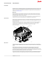
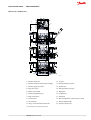
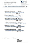
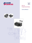
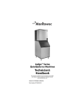
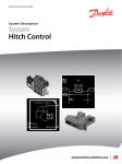
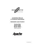
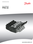
MAKING MODERN LIVING POSSIBLE
Technical Information
Proportional Valve Group
PVG 32 AG Modules
powersolutions.danfoss.com
Technical Information
PVG 32 AG Modules
Revision History
Table of Revisions
2
Date
Changed
Rev
Feb 2014
Converted to Danfoss layout – DITA CMS
AE
Mar 2012
Layout changes, and change in the table, page 21.
AD
Mar 2010
New back cover
AC
11051935 • Rev AE • Feb 2014
Technical Information
PVG 32 AG Modules
Contents
Literature reference for PVG products
Introduction
Function
Short overview...................................................................................................................................................................................5
Hitch control.......................................................................................................................................................................................5
Warning................................................................................................................................................................................................6
PVG 32 cross-sectional view
Technical data
PVG 32 technical parameters....................................................................................................................................................... 8
PVBZ basic module for EH auxiliary valve functions
PVBD, PVBZ with optional diverter feature
Principle description of PVBD diverter:.................................................................................................................................. 10
PVBZ-HS/HD, hitch control valves
General introduction.................................................................................................................................................................... 11
PVBZ-HS basic module (hitch single-acting)........................................................................................................................11
PVBZ-HD basic module (hitch double-acting).....................................................................................................................12
PVP with integrated HPCO
Modules and code numbers
Activation characteristics
Pressure drop characteristics
PVB, inlet basic modules..............................................................................................................................................................15
PVBZ auxiliary modules............................................................................................................................................................... 16
PVBZ-HS/-HD modules, PVBD diverter, multi-valve (for PVBZ-HD)............................................................................. 17
PVBS spools...................................................................................................................................................................................... 19
PVE.......................................................................................................................................................................................................19
End plates compatible with Metric PVG 32 program........................................................................................................20
Characteristic of oil flow, spool travel and voltage............................................................................................................22
Pressure drop characteristics of float spools........................................................................................................................23
Single acting spools characteristics for PVBZ-HS .........................................................................................................26
Pressure drop characteristic in lower mode position, max. spool travel..............................................................26
Spools characteristics for PVBZ-HD....................................................................................................................................26
Dimensions and schematic examples
Drawings for 5-section group....................................................................................................................................................29
Drawings for 3-section group....................................................................................................................................................30
Drawings for 2-section group....................................................................................................................................................32
11051935 • Rev AE • Feb 2014
3
Technical Information
PVG 32 AG Modules
Literature reference for PVG products
Literature reference
4
Literature title
Type
Order
number
PVG 32 Proportional valve group
Technical Information
520L0344
PVG 100 Proportional valve group
Technical Information
520L0720
PVG 120 Proportional valve group
Technical Information
520L0356
PVG 32 Metric ports
Technical Information
11051935
PVE series 4
Technical Information
520L0553
PVED-CC Electro-hydraulic actuator
Technical Information
520L0665
PVED-CX Electro-hydraulic actuator
Technical Information
11070179
Basic module for PVBZ
Technical Information
520L0721
PVSK module with integrated diverter valve and P-disconnect function
Technical Information
520L0556
PVPV / PVPM pump side module
Technical Information
520L0222
Combination module PVGI
Technical Information
520L0405
PVSP/M Priority module
Technical Information
520L0291
Hitch Control
System Description
User Manual
11036124
11033753
PVBZ
Data sheet
520L0681
PVBZ-HS
Data sheet
520L0956
PVBZ-HD
Data sheet
11035599
MC024-010 and MC024-012 Controllers
Data sheet
520L0712
11051935 • Rev AE • Feb 2014
Technical Information
PVG 32 AG Modules
Introduction
The PVG 32 valve was originally launched with a range of high-performance electrical actuators in 1988.
During recent years, several AG (agricultural) customer projects have motivated several innovations, and
today our valve program offers components and features as compiled in this Technical Information or
referred to the Literature reference.
Metric ports
We have developed a range of modules with metric ports. These modules comprise of various inlets,
working modules for auxiliary functions, hitch modules, special top mounted modules and endplates.
The range of our PVE - Series 4 is used as actuation.
The target application area for this product range is mainly Agriculture – especially complete EH valve
solutions for tractors, but also other applications can benefit from the offered features.
Short overview
Besides the inlets suited for fixed as well as for LS-controlled variable piston pumps, you will find a range
of valve modules listed. These valves enable you to assemble a valve solution using EH Aux valves and
hitch valves for tractors.
The PVE Series 4 generation with either analogue and digital pilot heads offers multiple possibilities of
customizing valves for individual needs – ranging from simple analogue versions to fully ISOBUS
compliant actuators with numerous variants in between, analogue as well as digital.
PVG 32 parts description
PVBZ-HD
PVBZ with Diverter
PVE
PVC
PVBZ
PVBZ-HS
PVML
PVM
PVP
V310070.A
Hitch control
Together with the introduction of this product range, Danfoss has developed a hitch control SW block
available in our PLUS+1® GUIDE which on base of a PLUS+1 controller can offer a Hitch control system for
tractors.
These components allow for design of hitch systems that incorporate intuitive control as well as a
number of innovative new solutions. The components available offer significant advantages in
controlling both the single and double acting systems, including easy understanding of both Force and
Slip control. In addition to performing state of the art operation of hitch, the software block contains logic
that ensures the full potential of the Danfoss hitch valves are exploited.
The technical information references mentioned describes the Danfoss concept behind the operation of
a hydraulic hitch system, and the different types of systems and components available from Danfoss.
11051935 • Rev AE • Feb 2014
5
Technical Information
PVG 32 AG Modules
Function
When main spools (15) are in neutral position, the pilot operated check valves (hereafter PO Check
valves) are kept closed by a spring plus the work port load, which is directed to the spring side of the PO
Check valves (14) via a small orifice.
If a main spool is actuated to have flow out of the B port, the meter out flow forces the respective PO
Check valves valve to open. At the same time, pilot pressure is guided via the main spool to the back side
of a small pilot valve (12) on the A port side. This will ensure that the load pressure behind the PO Check
valves is released to a separate tank T0 (20) via a seat valve and allow the PO Check valves to open and let
return flow pass across the main spool back to tank.
For float function, both PO Check valves are released to tank at the same time as described above.
In some applications with low load pressure, it is necessary to force open the PO Check valves by a pin
(17). This pin is actuated by means of pump pressure on the A port side.
PVBZ modules cannot be optionally mounted (PVM on A - Port side only).
The separate tank connection T0 is needed to ensure proper performance of the PO Check valvess
regardless of the pressure in main tank line T. It is therefore necessary to connect the T0 port in the Inlet
PVP direct to the oil reservoir with a separate hose, see dimensional drawing examples.
All the valve modules in this technical information have a T0 gallery.
When using PVP with HPCO function (T port can be pressurised) please make sure to lead return flow
from the A and B ports to tank via a separate tank port in the end plate PVST.
Warning
W
Warning
All makes and all types of directional control valves – inclusive proportional valves – can fail and cause
serious damage. It is therefore important to analyse all aspects of the application.
Because the proportional valves are used in many different operation conditions and applications, the
manufacturer of the application is responsible for making the final selection of the products- and
assuring that all performance, safety and warning requirements of the application are met.
The process of choosing the control system – and safety level – could e.g. be governed by ISO 13849
(Safety related parts of control system).
6
11051935 • Rev AE • Feb 2014
Technical Information
PVG 32 AG Modules
PVG 32 cross-sectional view
1
T
2
P
10
3
M
PVP
9
4+5
LS
11
8
6
7
12
14
A
B
PVBZ
13
15
16
B
17
A
PVBZ
B
B
A
PVBZ
A
20
19
18
V310138.A
1 – Pressure relief valve
11 – LS signal
2 – Pressure reduction valve for pilot oil supply
12 – Pilot operated check valves
3 – Pressure gauge connection
13 – Shuttle valve
4 – Plug, open center
14 – Pilot operated check valves
5 – Orifice, closed center
15 – Main spool
6 – Pressure adjustment spool
16 – Compensator
7 – Plug, closed center
17 – Shuttle pin
8 – LS connection
18 – Max. oil adjustment screws for ports A and B
9 – T0 connection
19 – Pilot oil supply for PVE
10 – Plug - to be removed for internal T0*
20 – Separate tank line (T0)
* for 157B: 5130, 5131, 5330 and 5331 only.
11051935 • Rev AE • Feb 2014
7
Technical Information
PVG 32 AG Modules
Technical data
PVG 32 technical parameters
Max. pressure
Oil flow, rated
Port P continuous
250 bar
[3625 psi]
Port A/B / without P/O checks
280 bar
[4061 psi]
Port T, static/dynamic
25 / 40 bar
[362 / 580 psi]
Port T Hitch Single-Acting Module
25 bar
[362 psi]
Port P
140 l/min
[37.0 US gal/min]
Port A/B, with press. comp.
100 l/min
[26.4 US gal/min]
± 7 mm
[±0.28 in]
Spool travel, standard
Spool travel,
float position spool
Proportional range
± 5.5 mm
[±0.22 in]
Float position
7.5 mm
[±0.30 in]
Dead band,
flow control spool
Standard
± 0.8 mm
[±0.03 in]
PVBZ with PO Check
valves
1 cm3/min
[0.06 in3/min]
PVBZ with PO Check
valves and PVLP
6 cm3/min
[0.37 in3/min]
PVB with PVLP
25 cm3/min
[1.53 in3/min]
Recommended
30 → 60°C
[86 → 140°F]
Min. temperature
-30°C
[–22°F]
Max. temperature
+90°C
[194°F]
Ambient temperature
-30 → +60°C
[–22 → +140°F]
Oil viscosity
Operating range
12 - 75 mm2/s
[65 - 347 SUS]
Min. viscosity
4 mm2/s
[39 SUS]
Max. viscosity
460 mm2/s
[2128 SUS]
Max. contamination (ISO 4406)
18/16/13
18/16/13
Max. internal leakage
A/B → T
at 200 bar [2900 psi]
and 21 mm2/s [102 SUS]
Oil temperature
(inlet temperature)
Filtration
PVBD, 6/2 diverter valve
Max pressure PVBZ module with mounted diverter PVBD, Port A/B
280 bar [4061 psi]
Oil flow max recommended, rated PVBZ module with mounted diverter
PVBD
80 l/min [21.1 US gal/min]
Multi-valve, Single-action / Double-action
8
Max pressure PVBZ module with mounted multi valve, Port A/B
280 bar [4061 psi]
Oil flow, rated PVBZ module with mounted multi valve, Port A/B
100 l/min [26.4 US gal/min]
11051935 • Rev AE • Feb 2014
Technical Information
PVG 32 AG Modules
PVBZ basic module for EH auxiliary valve functions
The PVBZ valve is a load and pressure compensated valve module with two pilot operated check valves
(PO Check valves) in the A- and B-ports. These are limiting the work port leakage to a very low limit,
below 1 cm3/min.
PVBZ modules will always have 2 PO Check valves one in each work port.
Besides compensation, the pressure compensator can limit the work port pressure blow up to 4 - 5 bar.
The special PVBZ load compensated module was developed for applications that require integrated pilot
operated check valves in the work ports that required to limit the port leakage to zero. See Technical data.
The PVBZ basic module can be mixed with basic modules PVB (with additional tank line T0).
Features:
•
•
•
•
•
•
•
•
Integrated pilot operated check valves for limited internal leakage
Can be mixed with PVB with T0 gallery
LS a/b shuttle for float spools
Standard 4/4 float spools
Integrated thermo relief valve as option (modules with threaded ports only)
Manifold version for Danfoss designed valves or customer designed quick coupler block
Compensator with bleed off
Auxiliary valve on tractors for function control on implements; cylinder positioning and speed control
of hydraulic motors.
PVBZ, load and pressure compensated valve module with two PO check valves in A/B-ports
PO Check valves
Pilot Valves
Analogue or Digital
CAN ISOBUS
Forced Opening Shuttle Pin
B
A
P301 015
PVM Manual Actuator
Pressure Compensator with bleed off
Inductive LVDT Sensor
PVE Actuator
PVBZ parameters
Maximum pressure
Oil flow, rated
Port P continuous
Port A/B
280 bar [4061 psi]
Port A/B, with press. comp.
100 l/min [26.4 US gal/min]
Spool travel, standard
Spool travel, float position spool
250 bar [3625 psi]
± 7 mm [±0.28 in]
Proportional range
± 5.5 mm [±0.22 in]
Float position
7.5 mm [±0.30 in]
Dead band,flow control spool
Standard
± 0.8 mm [±0.03 in]
Max. internal leakage at 150 bar [2175
psi] and 21 mm2/s [102 SUS]
A/B → T
1 cm3/min [0.06 in3/min]
11051935 • Rev AE • Feb 2014
9
Technical Information
PVG 32 AG Modules
PVBD, PVBZ with optional diverter feature
The utilization of a PVBZ module can be further enhanced by adding a diverter valve. Mounted on top of
the PVBZ valve slice, a 6/2 PVBD diverter valve can direct valve flow to either of two set of ports (A1/B1 or
A2/B2). The PVBD diverter spool (shift spool) is actuated by the PVC solenoid valve by means of pilot
pressure.
Features:
•
•
•
•
Enlarge the application range (2 functions)
To be mounted on top of PVB or PVBZ modules
Pilot operated with PVC
Auxiliary valve on tractors for function control on implements: cylinder positioning when the demand
on neutral port leakage is limited.
PVBD, PVBZ with optional diverter feature
PVBD (Diverter)
PVC
A1
A2
B1
B2
T0
A
Analogue or
Digital CAN
ISOBUS
B
Pilot supply
PO Check valve
Pilot Valve
PVE
Actuator
PVM Manual
Actuator
Pressure compensator with bleed off
Inductive LVDT Sensor
P301 096
Principle description of PVBD diverter:
•
•
PVC off: The shift spool is held in position (flow to A1/B1) by the spring in the right hand side
(opposite the PVC). The spring chamber is always connected to the T0 gallery in the PVBZ body.
PVC on: Pilot pressure is led into the chamber next to the PVC. A limited flow is passing through the
shift spool and the two orifices and into the spring chamber connected to T0. Pressure-drop across
the orifices creates the shift force moving the shift spool towards the spring. As a result, port A2/B2
becomes active.
Leakage (along the spool clearance) from pressurized work ports A1/B1 or A2/B2 will always be drained
to T0 either directly in the spring chamber or through the shift spool. This secures safe positioning of the
shift spool as leakage never will build up pressure up in the control chambers.
Safety recommendation: Shift of the diverter should only be possible when the main spool is in neutral.
This has to be ensured through a proper set-up in the controller/MMI hardware.
10
11051935 • Rev AE • Feb 2014
Technical Information
PVG 32 AG Modules
PVBZ-HS/HD, hitch control valves
General introduction
Two types of hitch valves are available for hitch or similar applications. The two valve options offered are
the PVBZ-HS, single acting and the PVBZ-HD, double acting.
The PVBZ-HS matches the market standard whereby implements are raised hydraulically and lowered
only by the pull of gravity. The PVBZ-HD has the unique ability to raise and lower either as single- or
double-acting.
The benefits of the PVBZ-HD reflect a departure from old hitch norms - increased comfort when attaching
implements due to the same speed up and down and safer detachment of heavy implements from the
driver’s seat.
The full benefit of the possibilities with the PVBZ-HD is easily obtained by use of the PLUS+1® hitch core
application block. The core application block shifts the valve between single- and double-acting hitch
according to the most suitable operation.
The operator will not have to select the operation but will notice the benefits during normal operation of
the hitch. Work-modes are single-acting as it is standard today, but manual operation up and down are
double-acting to increase comfort, functionality and safety.
For further info and more details please see the Danfoss Hitch control System description, see Literature
reference.
PVBZ-HS basic module (hitch single-acting)
Single acting PVBZ-HS slice for standard hitch application.
It has its own tank port to direct the return flow directly into the tank with a minimum of back pressure.
This prevents tank-line pressure influence, especially when lowering the un-loaded (empty) hitch under
cold conditions (high oil viscosity).
Similar to the auxiliary slice, the single acting PVBZ-HS slice is a pressure-compensated valve slice with
one P/O check valve on B-port only. The same technology as in the PVBZ module is used.
Besides the flow paths, the spool is directing the pilot pressure to the pilot valve for P/O check valve
pressure release as well as to the shuttle pin in order to force the P/O popped to open under low load
conditions. This ensures a fully open flow path in lower mode.
The B-port is normally equipped with a PVLP shock valve.
PVBZ-HS incorporates a compensator with bleed-off to prevent pressure building up between the pump
gallery and the work ports.
A special 3/3 spool with optimized flow characteristics, both in meter-out as well as in meter-in direction,
has to be controlled by a high performance actuator.
Features:
•
•
•
•
•
•
•
Low leakage work port
Separated tank port
Integrated PVLP shock/anti cavitation valves
Can be mixed with PVB/ PVBZ with T0 gallery
Compensator with bleed off
Rear-Hitch on tractors
Header control on combines and harvesters
11051935 • Rev AE • Feb 2014
11
Technical Information
PVG 32 AG Modules
PVBZ-HS/HD, hitch control valves
Hitch single-acting valve module
Analogue or
Digital CAN
ISOBUS
PVLP 63
B
T
Pilot supply
PO Check valve
Pilot Valve
PVM Manual
Actuator
PVE Actuator
Pressure Compensator with bleed off
Inductive LVDT Sensor
P301 095
PVBZ-HS parameters
Maximum pressure
Port P continuous
250 bar [3625 psi]
Port B
280 bar [4061 psi]
Port T, static/dynamic
25 bar/40 bar [365/580 psi]
Oil flow, rated, Port B, with press. comp.
100 l/min [26.4 US gal/min]
Spool travel, standard
± 7 mm [±0.28 in]
Dead band, flow control spool, standard
± 0.8 mm [±0.03 in]
Max. internal leakage at 150 bar [2175 psi] and
21 mm2/s [102 SUS]
B → T, with PVLP
6.0 cm3/min [0.37 in3/min]
Safety recommendations for the OEM and user.
To avoid unintended raise of the empty hitch the tank port on PVBZ-HS always has to be connected
direct to tank without any restriction or pressure build up possibilities.
This also ensures lowering in lower mode under cold conditions (high viscosity oil).
In case of manual actuation of the Hitch function (limp home mode) the power supply to the PVE has to
be disabled before the PVM (hexagon) can be actuated.
The OEM /end user needs to be aware of the dangerous operation when performing manual raise/
lowering of the hitch and be close to the hitch arms.
PVBZ-HD basic module (hitch double-acting)
The double-acting hitch slice consists of the PVBZ valve-section with a flanged-on single/double-acting
selector (multi-valve) actuated by a PVC valve.
By energizing or de-energizing the PVC, the multi-valve shifts the slice between single- or double-acting
work-modes. This is of great benefit in hitch applications both for rear and front hitches. When the slice is
operating as single-acting, the A-port is connected to tank in the PVBZ body.
The PVBZ base of the PVBZ-HD has similar features as the PVBZ valve-slice. That is PO Check valves for low
leakage as well as compensator with bleed-off to eliminate pressure build-up between compensator and
work-ports.
12
11051935 • Rev AE • Feb 2014
Technical Information
PVG 32 AG Modules
PVBZ-HS/HD, hitch control valves
The flanged on multi-valve contains the shifting spool to switch port A between T and port A of the PVBZ.
It also contains a PVLP shock/suction valve on port B.
The change between single- and double-acting modes is operated independently of valve-flow
command.
Features:
•
•
•
•
•
•
•
•
Low leakage work port (B-port)
Standard 4/4 float spools to be used
Electrical mode shift into pure 3/3 single acting functionality of double acting cylinder
Integrated PVLP shock/anti cavitation valves (B-port)
Single and Double Acting (see Hitch Control System Description for detailed set-up and benefits)
Compensator with bleed off
Rear and front hitch linkages on medium and higher performance tractors.
Header control on combines and harvesters.
Hitch double-acting valve module
PVC
Mode shift spool
A
B
PVLP 63
Analogue or
Digital CAN
ISOBUS
LS
B
A
Tank
PO Check valves
Pilot Valve
Pilot Supply
PVE
Actuator
PVM Manual
Actuator
Pressure Compensator with bleed off
Inductive LVDT sensor
P301 094
PVBZ-HD parameters
Maximum pressure
Port P continuous
250 bar [3625 psi]
Port A/B
280 bar [4061 psi]
Oil flow, rated
Port A/B, with press. comp.
100 l/min [26.4 US gal/min]
Pilot oil consumtion
PVC off / PVC on
0 / 0.3 l/min
Environmental specifications
Temperature oil viscosity etc.
See PVBZ parameters
PVC solenoid (NC)
Connector type Zener diode included
AMP JPT 2 Pin
11051935 • Rev AE • Feb 2014
13
Technical Information
PVG 32 AG Modules
PVP with integrated HPCO
Together with the introduction of PVBZ (and PVB with separate tank line T0). Danfoss can now also
supply PVG 32 valves with integrated HPCO functionality (High Pressure Carry Over).
The HPCO function will guide the pump flow not used in the PVG 32 valve group via the HPCO port to for
example a directional valve. The PVP pump side module with integrated HPCO function can only be
mixed with PVB, PVBZ and PVST.
Features:
•
•
•
14
HPCO functionality
Prioritized flow for PVG 32
Reduced plumbing
11051935 • Rev AE • Feb 2014
Technical Information
PVG 32 AG Modules
Modules and code numbers
PVB, inlet basic modules
PVB, inlet basic modules
Symbol
P
Descriptions: PVP / PVPV / PVB
Ports
Code number
PVP, Open centre pump side module for pumps
with fixed displacement.
External T0. With pilot supply for electrical
actuation.
P: M27x2
T: M27x2
M: M14x1.5
LS: M14x1.5
T0: M14x1.5
11072195
(ISO 6149)
PVP, Open centre pump side module for pumps
with fixed displacement.
External T0. With pilot supply for electrical
actuation.
Prepared for HPCO - use Tport.
PVG group requires PVST (end plate with T port).
P: M27x2
T: M27x2
(HPCO)
M: M14x1.5
LS: M14x1.5
T0: M14x1.5
157B5961
(ISO 6149)
PVP, Open centre pump side module for pumps
with fixed displacement
External T0
With pilot supply for electrical actuation.
Measure port for pilot supply.
P: M22x1.5
P2: M16x1.5
T: M22x1.5
M: M10x1
LS: M12x1.5
T0: M16x1.5
Ppilot: M10x1
157B5964
(DIN 3851)
PVP, Open centre pump side module for pumps
with fixed displacement.
External T0. With pilot supply for electrical
actuation.
Prepared for HPCO - use Tport.
PVG group requires PVST (end plate with T port).
P: M22x1.5
P2: M16x1.5
T: M22x1.5
(HPCO)
M: M10x1
LS: M12x1.5
T0: M16x1.5
Ppilot: M10x1
157B5965
(DIN 3851)
PVPV, Closed centre pump side module for
pumps with variable displacement.
External T0.
With pilot supply for electrical actuation.
Prepared for PVLP.
P: M33x2
T: M33x2
T2: M14x1.5
M: M14x1.5
LS: M14x1.5
T0: M16x1.5
157B5969
(ISO 6149)
PVPV, Closed centre pump side module for
pumps with variable displacement.
External T0.
With pilot supply for electrical actuation.
P, T: M27x2
P2, T2:
M14x1.5
LS: M14x1.5
T0, T02:
M14x1.5
11003806
(ISO 6149)
T
T0 M
P301 032
T(HPCO)
P
LS
LS
T0 M
Pp
P301 033
P
T
T0 M
P2 LS P301 034
P
T (HPCO)
Inlet
PVP 157B5965
w. HPCO
Pp
T0 M
P2 LS P301 035
P
T2
T
T0
M
LS
P301 036
P2
P
T0
T2
T
T02
LS
P301 037
11051935 • Rev AE • Feb 2014
15
Technical Information
PVG 32 AG Modules
Modules and code numbers
PVB, inlet basic modules (continued)
Symbol
Descriptions: PVP / PVPV / PVB
Ports
Code number
PVPV,
Closed centre pump side module for pumps with
variable displacement.
External T0 without pilot supply.
P: M27x2
P2: M14x1.5
T: M27x2
T2: M14x1.5
LS: M14x1.5
T0: M16x1.5
T02: M14x1.5
11055758
(ISO 6149)
PVB,
With compensator, without thermal relief valve
T0 facility
LS a/b shuttle valve
Prepared for PVLP shock valves
M22 x 1.5
157B6850
(ISO 6149)
PVB,
With compensator
T0 facility
LS a/b shuttle valve
Prepared for manifold PVBD
Manifold PVBD 157B6969
Symbol
Description PVB / PVBZ
Port
Code number
M22 x 1.5
B
PVBZ as PVB
Compensator w. bleed off and check valve
T0 facility
LS a/b shuttle valve
Without thermal relief valve
157B6955
(ISO 6149)
PVBZ 2 PO check valves
Compensator w. bleed off and check valve
T0 facility
LS a/b shuttle valve. Shuttle pin.
Without thermal relief valve
M22 x 1.5
157B6957
(ISO 6149)
P2
P
LS
T2
T
T0
T02
V310061.A
B
A
T0 Pp
LSP T
P301 038
B
T0
A
Pp
P301 039
PVBZ auxiliary modules
PVBZ auxiliary modules
A
P301 040
B
A
P301 041
16
11051935 • Rev AE • Feb 2014
Technical Information
PVG 32 AG Modules
Modules and code numbers
PVBZ auxiliary modules (continued)
Symbol
B
Description PVB / PVBZ
Port
Code number
PVBZ 2 PO check valves.
Compensator w. bleed off and check valve
T0 facility
LS a/b shuttle valve. Shuttle pin.
Without thermal relief valve
M22 x 1.5
11024817
(DIN 3851)
PVBZ 2 PO check valves.
Compensator w. bleed off and check valve
T0 facility
LS a/b shuttle valve. Shuttle pin.
With thermal relief valve
M22 x 1.5
157B6954
(ISO 6149)
PVBZ 2 PO check valves.
Shuttle pin.
Compensator w. bleed off and check valve
T0 facility
LS a/b shuttle valve, LS return
With thermal relief valve
Manifold PVBD 157B6958
PVBZ 2 PO check valves.
Shuttle pin.
Compensator w. bleed off and check valve
T0 facility
LS a/b shuttle valve, LS return
Quick coupler block manifold
Manifold
Special
interface
11005475
Description PVBZ
Port
Code number
PVBZ-HS with PO Check valve in B port.
Compensator w. bleed off and check valve
T0 facility
Valve for 3/3 spool - single acting only!
B-port prepared for PVLP
Own T port - enables lowering of no loaded
actuator.
M22 x 1.5
157B6968
(ISO 6149)
A
P301 042
B
A
T0 Pp
LS PT
P301 043
B
T0
A
Pp
P301 044
T0
B
A
T0
P301 045
PVBZ-HS/-HD modules, PVBD diverter, multi-valve (for PVBZ-HD)
PVBZ-HS/-HD modules
Symbol
B
T
P301 046
11051935 • Rev AE • Feb 2014
17
Technical Information
PVG 32 AG Modules
Modules and code numbers
PVBZ-HS/-HD modules (continued)
Symbol
B
T0
LS
A
T
Pp
Description PVBZ
Port
Code number
PVBZ with PO check valves.
Compensator w. bleed off and check valve
T0 facility
LS a/b shuttle valve; LS return; Shuttle pin
manifold for multi-valve for PVBZ-HD
manifold for
multi-valve
11032961
Description
Port
P301 047
PVBD diverter, multi-valve (for PVBZ-HD)
Symbol
B1
B
T0
B2
157B1501
(ISO 6149)
Multi-valve for PVBZ 11032961
M22 x 1.5
Valve shifts A-port between PVBZ A or tank
gallery, i.e. shifts between single and double
acting actuation.
B-port prepared for PVLP
Actuated with included PVC solenoid; PVC NC; 12
VDC; 14 bar.
Port max. pressure: 280 bar
Connector type: AMP JPT 2 PIN
11027604
(ISO 6149)
157B1503
A1
Code Number
PVBD 6/2 shift valve.
M22 x 1.5
Valve shifts between A1 & B1 / A2 & B2.
Actuated with included PVC solenoid; PVC NC; 12
VDC; 14 bar.
Port max. pressure: 280 bar
Connector type: AMP JPT 2 PIN
A
A2
Pp
P301 048
B
B
T0
LS
A
A
T
Pp
P301 049
18
11051935 • Rev AE • Feb 2014
Technical Information
PVG 32 AG Modules
Modules and code numbers
PVBS spools
PVBS spools
Symbol
Description PVBS
Pressure compensated flow l/min
5 [1.32]
10 [2.64]
25 [6.6]
40 [10.57]
65 [17.17]
100 [22]
11051945
11019630
11019631
11019633
11019634
11019635
Standard FC -spools for PVBZ and PVBZ- 157B9415
HD
(Electrical and Mechanical actuation)
Tension bar for PVM
Check valve in spool
4-way, 4-position
Float >A>F
Deadband: 0,8 mm
For PVBZ with LS A/B shuttle
157B9410
157B9411
157B9412
157B9413
157B9414
Standard FC-spools for PVBZ
(Electrical and Mechanical actuation)
Tension bar for PVM
Check valves in spool
4-way, 3-position
Deadband: 0,8 mm
For PVBZ with LS A/B shuttle
Standard FC float spools for PVBZ
(Electrical actuation)
Tension bar for PVML
Check valve in spool
4-way, 4-position
Float >A>F
Deadband: 0,8 mm
For PVBZ with LS A/B shuttle
P -> B / B -> T
Standard FC spools for PVBZ-HS
(Electrical and Mechanical actuation)
Tension bar for PVM
3-way, 3-position
Deadband: 0,8 mm
157B9434
50/30
75/50
100/65
11023550
11023551
11023552
PVE
PVE
Symbol
Description of PVE*
Code Number
AMP
PVEH-F
Ratiometric proportional high, Active fault monitoring
Multi-voltage 11-32 V, hysteresis: 4% rated
Float P>A>F by additional input signal.
Recommended use: PVB_ PVBZ with float spools.
PVEP-F
PWM proportional high, Active fault monitoring
Multi-voltage 11-32 V, hysteresis: 5% rated
Float P>A>F by additional input signal.
Recommended use: PVB_ PVBZ with float spools.
11051935 • Rev AE • Feb 2014
Deutsch
157B4338
157B4753
19
Technical Information
PVG 32 AG Modules
Modules and code numbers
PVE (continued)
Symbol
Description of PVE*
Code Number
AMP
Deutsch
PVED-CC
Can bus proportional high, Programmable
Multi-voltage 11-32 V, hysteresis: ~ 0%
Recommended use: PVB_ PVBZ with float spools.
157B4943
157B4944
PVED-CC
Can bus proportional high, Programmable
Multi-voltage 11-32 V, hysteresis: 4% rated
Recommended use: PVBZ-HS or PVBZ-HD hitch valves
11026781
11015692
PVEP
Proportional actuation, Active fault monitoring
11034832
* For further information see PVE series 4 Technical Information, 520L0553.
End plates compatible with Metric PVG 32 program
End plates compatible with Metric PVG 32 program
Symbol
Description PVS
Port
Code Numbers
ISO
PVS aluminum
Without active elements
No connections
DIN
157B2000 157B2000
V310062.A
PVS aluminum
Without active elements
LX connection
LX
LX: M12x1.5
157B2913
V310063.A
PVSI steel
Without active elements
No connections
157B2014 157B2014
V310062.A
LX
PVSI steel
Without active elements
LX connection
LX: M12x1.5
157B2910
PVST steel
Without active elements
T-port
M8 for mounting
T: M22x1.5
11004462
V310063.A
T
V310064.A
20
11051935 • Rev AE • Feb 2014
157B2912
Technical Information
PVG 32 AG Modules
Modules and code numbers
End plates compatible with Metric PVG 32 program (continued)
Symbol
Description PVS
Port
Code Numbers
ISO
T P LS
Pp
T2
LX
Pp
LX on/off
T0
Pp
PVSI Steel
With pilot supply for electrical actuation
and pilot dump.
LX-connection
LX on/off
350 bar
12 VDC
LX: M14x1.5
T2: M22x1.5
Pp: M14x1.5
11050065
PVSI Steel
350 bar
With pilot supply for electrical actuation
T0: M14x1.5
157B2917
DIN
V310060.A
LS P T
T0
V310076.A
Separate specification pads with 50 sheets are available under the literature no. 520L0515.
11051935 • Rev AE • Feb 2014
21
Technical Information
PVG 32 AG Modules
Activation characteristics
Characteristic of oil flow, spool travel and voltage
•
•
•
•
The spools have 5.5 mm spool travel in direction B and 7.5 mm travel in direction A:
5.5 mm spool displacement in direction A gives max. oil flow to port A
5.5 mm spool displacement in direction B gives max. oil flow to port B
7.5 mm spool displacement in direction A gives completely open float position A/B → T
Characteristic of oil flow, spool travel and voltage
22
11051935 • Rev AE • Feb 2014
Technical Information
PVG 32 AG Modules
Pressure drop characteristics
Pressure drop characteristics of float spools
A/B → T at max. spool travel 5.5 mm (A or B) or 7.5 mm float position. Shown curves are typical average
values of return pressure drops on 1. Position in a PVBZ module (157B5957) to the T-port (M27) on a PVPV
inlet.
Pressure drop A/B → T characteristic for PVBS: 157B9414 and 157B9434
Pressure drop A/B to T : PVBS 157B9414 &157B9434
30
28
26
Pressure drop A/B - T [bar]
24
22
A → T (5.5 mm)
20
18
16
A → T (float)
14
12
B → T (5.5 mm)
10
8
B → T (float)
6
4
2
0
0
10
20
30
40
50
60
70
80
90
100
110
Q (A/B) [l/min]
120
P301 087
Pressure drop A/B → T characteristic for PVBS: 157B9413
Pressure drop A/B to T : PVBS 157B9413
50
Pressure drop A/B - T [bar]
45
40
35
A → T (5.5 mm)
30
25
B → T (5.5 mm)
20
A → T (float)
15
B → T (float)
10
5
0
0
10
20
30
11051935 • Rev AE • Feb 2014
40
50
60
70
Q (A/B) [l/min]
80
90
100
110
120
P301 088
23
Technical Information
PVG 32 AG Modules
Pressure drop characteristics
Pressure drop A/B → T characteristic for PVBS: 157B9642
Pressure drop A/B to T : PVBS 157B9642
60
A → T (5.5 mm)
55
Pressure drop A/B - T [bar]
50
45
B → T (5.5 mm)
40
35
30
25
20
A → T (float)
15
10
B → T (float)
5
0
0
10
20
30
40
50
60
70
80
90
100
110
Q (A/B) [l/min]
120
P301 089
Pressure drop A/B → T characteristic for PVBS: 157B9411
Pressure drop A/B to T : PVBS 157B9411
25
Pressure drop A/B - T [bar]
A → T (5.5 mm)
20
B → T (5.5 mm)
15
10
A → T (float)
5
B → T (float)
0
0
10
20
30
40
Q (A/B) [l/min]
24
11051935 • Rev AE • Feb 2014
50
60
70
80
P301 090
Technical Information
PVG 32 AG Modules
Pressure drop characteristics
Pressure drop A/B → T characteristic for PVBS: 157B9410
Pressure drop A/B to T : PVBS 157B9410
25
A → T (5.5 mm)
B → T (5.5 mm)
Pressure drop A/B - T [bar]
20
15
10
5
A → T (float)
B → T (float)
0
0
10
20
30
40
50
Q (A/B) [l/min]
60
P301 091
Pressure drop A/B → T characteristic for PVBS: 157B9415
Pressure drop A/B to T : PVBS 157B9415
50
45
A → T (5.5 mm)
Pressure drop A/B - T [bar]
40
B → T (5.5 mm)
35
30
25
20
15
10
A → T (float)
5
B → T (float)
0
0
10
20
Q (A/B) [l/min]
11051935 • Rev AE • Feb 2014
30
40
P301 092
25
Technical Information
PVG 32 AG Modules
Pressure drop characteristics
Single acting spools characteristics for PVBZ-HS
3/3 spools characteristic for PVBZ-HS 157B9411 Oil flow, spool travel and voltage
3/3 spools for PVBZ-HS
Characteristics; Oil flow, spool travel and voltage
120
100L _11023552
100
Flow /l/min)
80
75 L _11023551
60
40
50 L _11023550
20
0
0
1
0.50
2
3
0.55
4
0.60
5
6
0.65
7
0.70
Spool travel
mm
Us
PVE
UDC
0.75
P301 093
B → T at max. spool travel 7.0 mm. Shown curves are typical average values of return pressure drops on 1.
Position in a PVBZ_HS module to the T-port (M27) on a PVPV inlet.
Pressure drop characteristic in lower mode position, max. spool travel
Pressure drop B → T characteristic for PVBS 111023550, 111023551 and 111023552
Pressure drop B to T: PVBS 11023550, 11023551 & 11023552
120
Pressure drop B - T [bar]
100
80
B → T (7 mm)
50 L _11023550
60
B → T (7 mm)
75 L _11023551
40
20
B → T (7 mm)
100L _11023551
0
0
10
20
30
40
50
60
Q (B) [l/min]
70
80
90
100
110
P301 097
Spools characteristics for PVBZ-HD
Normally float spools as for PVBZ basic modules are recommended for the PVBZ-HD solution. See
Activation characteristics.
Pressure drop characteristics for the PVBZ-HD valve are shown in the following example using a 100l float
spool code no.: 157B9414 at the respective spool travel and multi-valve mode position.
26
11051935 • Rev AE • Feb 2014
Technical Information
PVG 32 AG Modules
Pressure drop characteristics
Shown curves are typical average values of return pressure drops on 1. Position in a PVBZ-HD module to
the T-port (M27) on a PVPV inlet.
Pressure drop B → T characteristic for PVBS 157B9414; PVBZ-HD double acting mode
Pressure drop B to T - PVBS 157B9414
PVBZ-HD Double acting mode
25
20
Pressure drop B - T [bar]
B → T (5.5 mm)
15
10
5
0
0
10
20
30
40
50
60
70
80
90
100
110
Q (B) [l/min]
120
P301 098
Pressure drop A → T characteristic for PVBS 157B9414; PVBZ-HD double acting mode
Pressure drop A to T - PVBS 157B9414
PVBZ-HD Double acting mode
40
35
Pressure drop A - T [bar]
30
A → T (5.5 mm)
25
20
A → T (float)
15
10
5
0
0
10
20
30
40
50
60
Q (A) [l/min]
11051935 • Rev AE • Feb 2014
70
80
90
100
110
120
P301 099
27
Technical Information
PVG 32 AG Modules
Pressure drop characteristics
Pressure drop A → T characteristic; PVBZ-HD single acting mode
Pressure drop A to T
PVBZ-HD Single acting mode
120
110
100
PVBS
independently
Pressure drop A - T [bar]
90
80
70
60
50
40
30
20
10
0
0
10
20
30
40
50
60
Q (A) [l/min]
28
11051935 • Rev AE • Feb 2014
70
80
90
100
110
120
P301 100
Technical Information
PVG 32 AG Modules
Dimensions and schematic examples
Drawings for 5-section group
•
•
•
Example of PVG 32: 5 sections valve group with 1 double acting hitch (PVBZ-HD), with 1 aux. valve
PVBZ with PVBD diverter valve slice, 2 aux. valves PVBZ and 1 aux. valve PVB.
To be supplied with LS variable piston pump.
PVED-CC with APM-JPT connector.
Example of PVG 32: 5 sections valve group with 1 double acting hitch (PVBZ-HD), with 1 PVBZ with PVBD diverter, 2 PVBZ, 1 PVB
A
B
A2
B2
A1
B1
A
B
A
B
A
B
T0
T02
LS
T T2
PVPV
11003806
P301 077
P P2
PVBZ-HD
11032961
11027604
PVBZ-PVBD
157B6958
157B1503
11051935 • Rev AE • Feb 2014
PVBZ
157B6957
PVBZ
157B6957
PVB
157B6850
PVS
157B2000
29
Technical Information
PVG 32 AG Modules
Dimensions and schematic examples
Drawing for 5-section valve group
172
125,5
140
172
View
X-X
F
H
G
K
95
I
L
J
35
48
48
X
12
336
12
19,5
23
68
33,5
X
P
N
37,5
38,5
69,3
38
34
36
34
89,6
46
62
95
302,6
P301 076
O
M
F: Port T2; M14 x 1.5
L: PVBZ A and B port; M22 x 1.5
G: Port T0; M14 x 1.5
M: Port P and T; M27 x 2.0
H: Port LS; M14 x 1.5
N: Port P2; M14 x 1.5
I: Port T02; M14 x 1.5
O: PVBZ-HD work port; M22 x 1.5
J: PVB A and B port; M22 x 1.5
P: PVBD work port; 4 x M22 x 1.5
K: Fixing holes; M8 x min. 10
Drawings for 3-section group
•
•
•
30
Example of PVG 32: 3 section valve group,with 1 htch single acting (PVBZ-HS) and 2 aux. valve slices.
To be supplied with LS variable piston pump.
PVED-CC with Deutsch DT connector.
11051935 • Rev AE • Feb 2014
Technical Information
PVG 32 AG Modules
Dimensions and schematic examples
Example of PVG 32: 3 sections valve group with 1 single acting hitch (PVBZ-HS) and 2 aux. valve slices.
T
B
A
B
A
B
T0
T02
LS
T T2
PVPV
11003806
P301 079
P P2
PVBZ-HS
PVBZ
PVBZ
PVS
157B6968
157B6957
157B6957
157B2000
11051935 • Rev AE • Feb 2014
31
Technical Information
PVG 32 AG Modules
Dimensions and schematic examples
Drawing for 3-section valve group
F
129,8
133,3
View
X-X
H
G
95
K
I
J
X
48
35
X
12
238
48
23
68
N
37,5
38,5
62
276
P301 078
L
M
F: Port T2; M14 x 1.5
K: Fixing holes; M8 x min. 10
G: Port T0; M14 x 1.5
L: PVBZ-HS work port B and T; M22 x 1.5
H: Port LS; M14 x 1.5
M: Port P and T; M27 x 2.0
I: Port T02; M14 x 1.5
N: Port P2; M14 x 1.5
J: PVB A and B port; M22 x 1.5
Drawings for 2-section group
•
•
•
•
32
PVG 32: 2 section valve group, typical example for Loader application for tractors.
To be supplied with fixed pump.
The PVP inlet has HPCO feature, consequently the PVT has tank port.
PVED-CC with APM-JPT connector.
11051935 • Rev AE • Feb 2014
Technical Information
PVG 32 AG Modules
Dimensions and schematic examples
Example of PVG 32: 2 section valve group, typical example for Loader application for tractors.
A
B
A
B
T
PVEH
PVEH
T0
M
LS
HPCO
PVP
157B5961
P301 081
P
PVBZ
157B6957
11051935 • Rev AE • Feb 2014
PVBZ
157B6957
PVST
11004462
33
Technical Information
PVG 32 AG Modules
Dimensions and schematic examples
Drawing for 2-section valve group
G
124,8
125,5
View
X-X
H
K
J
F
X
20,5
X
48
36,5
189
32
16
29
I
87,5
22,5
M
L
L
68
72,5
276
P301 080
34
F: Port T; M22 x 1.5
J: Port A and B; M22 x 1.5
G: Port T0; M14 x 1.5
K: Fixing holes; M8 x min. 10
H: Port LS; M14 x 1.5
L: Port P & HPCO; M27 x 2.0
I: Port M gauge; M14 x 1.5
M: Pressure relief valve
11051935 • Rev AE • Feb 2014
Technical Information
PVG 32 AG Modules
11051935 • Rev AE • Feb 2014
35
Products we offer:
• Bent Axis Motors
• Closed Circuit Axial Piston
Danfoss Power Solutions is a global manufacturer and supplier of high-quality hydraulic and
electronic components. We specialize in providing state-of-the-art technology and solutions that
excel in the harsh operating conditions of the mobile off-highway market. Building on our extensive
applications expertise, we work closely with our customers to ensure exceptional performance for a
broad range of off-highway vehicles.
• Displays
• Electrohydraulic Power
We help OEMs around the world speed up system development, reduce costs and bring vehicles to
market faster.
Danfoss – Your Strongest Partner in Mobile Hydraulics.
Pumps and Motors
Steering
•
•
•
•
Electrohydraulics
Go to www.powersolutions.danfoss.com for further product information.
Hydraulic Power Steering
Wherever off-highway vehicles are at work, so is Danfoss.
Integrated Systems
We offer expert worldwide support for our customers, ensuring the best possible solutions for
outstanding performance. And with an extensive network of Global Service Partners, we also provide
comprehensive global service for all of our components.
Joysticks and Control
Handles
• Microcontrollers and
Please contact the Danfoss Power Solution representative nearest you.
Software
• Open Circuit Axial Piston
Pumps
•
•
•
•
•
•
Orbital Motors
PLUS+1® GUIDE
Proportional Valves
Sensors
Steering
Transit Mixer Drives
Comatrol
www.comatrol.com
Schwarzmüller-Inverter
www.schwarzmuellerinverter.com
Local address:
Turolla
www.turollaocg.com
Valmova
www.valmova.com
Hydro-Gear
www.hydro-gear.com
Daikin-Sauer-Danfoss
www.daikin-sauer-danfoss.com
Danfoss
Power Solutions US Company
2800 East 13th Street
Ames, IA 50010, USA
Phone: +1 515 239 6000
Danfoss
Power Solutions GmbH & Co. OHG
Krokamp 35
D-24539 Neumünster, Germany
Phone: +49 4321 871 0
Danfoss
Power Solutions ApS
Nordborgvej 81
DK-6430 Nordborg, Denmark
Phone: +45 7488 2222
Danfoss
Power Solutions
(Shanghai) Co. Ltd.
Building #22, No. 1000 Jin Hai Rd
Jin Qiao, Pudong New District
Shanghai, China 201206
Phone: +86 21 3418 5200
Danfoss can accept no responsibility for possible errors in catalogues, brochures and other printed material. Danfoss reserves the right to alter its products without notice. This also applies to
products already on order provided that such alterations can be made without subsequential changes being necessary in specifications already agreed.
All trademarks in this material are property of the respective companies. Danfoss and the Danfoss logotype are trademarks of Danfoss A/S. All rights reserved.
11051935 • Rev AE • Feb 2014
www.danfoss.com
© Danfoss A/S, 2014