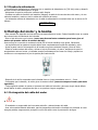
1
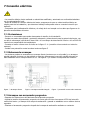
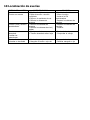
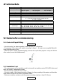
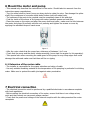
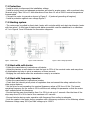
Manual de instrucciones de montaje y servicio Motores sumergibles rebobinables SACI 6” – 8” – 10” 1. Generalidades….………………………………………………………………………………………..1 1.1 Indicaciones y Símbolos………………………………………………………………………………….1 2. Seguridad….……………………………………………………………………………….……………….1 2.1 Utilización…………………………………………………………………………………….………………..1 2.2 Pérdida de Garantía……………………………………………………………………..………………….1 2.3 Instrucciones generales de seguridad…………..…….……………………….…………………..1 3. Transporte y Almacenaje…………………………………………………….…………………..2 3.1 Almacenaje…………………………………………………….……………………….…………………….2 3.2 Transporte………………………………………………………..……………………..…………………...2 3.3 Desembalaje………………………………………………………..…………………..…………………...2 3.4 Eliminación de residuos…………………………………………………………….…………………….2 4. Datos técnicos……………………………………………………………….…………………...2 5. Verificaciones antes de la puesta en marcha…………………………………….3 5.1 Control del líquido de llenado……………………………………………………………………………3 5.2 Prueba de aislamiento………………………………………………….………………………………….3 6. Montaje del motor y de la bomba………………………..…………………………….3 6.1 Prolongación del cable del motor……………………………………..……………………………...3 7. Conexión eléctrica……………………………………………………….…………………………...4 7.1 Protecciones…………………………………………………………………………..………………………4 7.2 Sistemas de arranque…………………………………………………………………….………………..4 7.3 Arranque con arrancador progresivo………………………………………………….……………..4 7.4 Arranque con variador de frecuencia…………………………………………………………………4 7.5 Alimentación con grupo generador…………………………………………………….………………4 8. Puesta en marcha……………………………………………………………………….………………5 8.1 Comprobaciones………………………………………………………………………………….………….5 9. Mantenimiento……………………………………………………………………………………..…….5 10. Localización de averías………………………………………………………………………..….5 1 Contenido de este manual Este manual de instrucciones forma parte integra del motor sumergible rebobinable y explica su manipulación segura en todas sus fases operativas. Estas instrucciones contienen información importante que han de respetarse al instalar y hacer funcionar el motor, de modo que tanto quien lo instala como el operador responsable debe leerlas antes de instalar el motor o hacerlo funcionar, Usted deberá seguir no solo las instrucciones que aparecen en este apartado; sino las que figuran en todos los demás apartados que se hayan puesto de relieve mediante símbolos de seguridad Este manual se debe conservar para su posterior utilización en algún lugar accesible al personal técnico autorizado. Este manual de instrucciones solo es valido para los motores sumergibles que en el se especifican 1-1 Indicaciones de advertencia y símbolos Las instrucciones de seguridad contenidas en este manual de instrucciones que, en caso de no seguirse pueden causar lesiones personales o desperfectos en el motor están señalas mediante el símbolo: Las instrucciones de seguridad que advierten de un peligro procedente de la corriente eléctrica están señaladas mediante el símbolo Las instrucciones de seguridad contenidas en este manual de instrucciones que en caso de no seguirse pueden causar daños al motor o la instalación y provocar su avería están señalizadas mediante el símbolo ¡CUIDADO! 2 Seguridad Este apartado describe las instrucciones de seguridad que deben seguirse para una correcta manipulación de los motores, y se mencionan las medidas de seguridad necesarias a adoptar en caso de existir alguna posible fuente de peligro. 2-1 Utilización Los motores sumergibles están diseñados para el accionamiento de bombas sumergibles bajo el agua mediante el acoplamiento a un grupo hidráulico, este deberá cumplir las condiciones de funcionamiento y prescripciones legales establecidas. 2-2 Perdida de garantía Los motores sumergibles solo deben ser usados en agua fría, limpia y clara. No deben ser usados en residual, líquidos inflamables o explosivos. El fabricante no se responsabiliza de los daños resultantes derivados de una utilización diferente a la indicada. El riesgo que esto conlleva es única responsabilidad del usuario 2-3 Instrucciones Generales de Seguridad Las siguientes normas generales de seguridad deben ser leídas antes de la puesta en marcha del motor: - Utilizar el motor solo bajo el agua (el motor y el cable del motor deben estar completamente sumergidos) - No efectuar ningún cambio o conversión ni al motor ni a sus conexiones eléctricas - No abrir nunca el motor - No utilizar nunca el motor con bombas o piezas dañadas - Realizar trabajos solo con el motor parado. No es necesario realizar ninguna revisión o control durante el funcionamiento - Desconectar la tensión del motor durante todos los trabajos, Asegurarse de que nadie puede, por descuido volver a conectar la tensión mientras se trabaja en el motor - No trabajar nunca en instalaciones eléctricas durante una tormenta - Antes de poner en marcha el motor comprobar que todas las conexiones eléctricas y dispositivos de seguridad han sido revisados y que todos los fusibles y protecciones ha sido ajustados correctamente - Asegurarse de que no se puede acceder libremente a ninguna zona peligrosa, partes eléctricas, partes giratorias, zonas de succión, bocas de salida, etc.... - Las reparaciones solo deben ser efectuadas por personal cualificado y en un taller especializado, utilizar solo piezas de repuesto originales 3 Transporte, almacenaje y eliminación de residuos 3-1 Almacenaje - El motor debe conservase en su embalaje hasta el momento de su instalación. Si el motor está almacenado de manera vertical, asegurarse de que no pueda volcarse. Mantener siempre el eje hacia arriba. No almacenar el motor de manera que pueda recibir directamente los rayos del sol u otras fuentes de calor - Observar la temperatura de almacenaje (-15ºC y +60ºC) 3-2 Transporte La caída de la carga puede causar fallecimiento o aplastamiento de extremidades PELIGRO - Nadie deberá permanecer por ningún motivo debajo de la carga suspendida - Use solo dispositivos elevadores o maquinas de carga apropiadas para este tipo de trabajo - Situar el punto de enganche en el centro de gravedad de la carga 3-3 Desembalaje - Evite cualquier golpe o impacto sobre el motor tenga cuidado al abrir el embalaje de no dañar el cable del motor después de desembalar el motor compruebe que no hay ningún daño, en carcasa, eje, o cables - En caso de observar cualquier anomalía informar inmediatamente al proveedor PELIGRO Peligro de muerte por descarga eléctrica si el cable se encuentra dañado No instalar el motor ni poner en funcionamiento si observa que el cable está dañado 3-4 Eliminación de residuos - Para evitar dañar el medioambiente, Eliminar el embalaje de modo apropiado para no dañar el medioambiente y prevenir la contaminación producida por lubricantes detergentes, etc..., tenga en cuenta las leyes locales sobre el medioambiente. 4 Datos técnicos Denominación Potencia y Modelo Aislamiento del bobinado Valor Motor 6” 4-45 KW Motor 8” 30-110 KW Motor 10” 92-185 KW PP Estándar PP Estándar PP Estándar PE2+PA Opcional PE2+PA Opcional PE2+PA Opcional Gama de Tensiones Tolerancia de la tensión Revoluciones Formas de arranque Nº Máximo de arranques Por hora Estándar de fabricación Profundidad de inmersión Posición de instalación 230 V 400 V 3 50 HZ ( Otras tensiones bajo pedido ) De -10% hasta +6% sobre la tensión de 220 - 380 V Aprox. 2900 revoluciones/min. a 50 Hz Arranque directo, estrella triangulo Motor 6” 20 arranques hasta 30 KW ; 10seg para el 6” 37-45 KW con intervalos entre los arranques de 90 s; Para los motores de 8” y 10” 10 arranques IP-68 IEC - 60034-1 Max. 350 m Carga axial sobre el motor Cables de connexion Brida de acoplamiento Control de temperatura Liquido del motor Refrigeración mínima Vertical ( eje hacia arriba ) Horizontal ( consultar con su distribuidor ) 6” 4-26 KW - 17 KN 30-45 - KW 30 KN 8” 30-45 KW - 30 KN 45-81 - KW 45 KN 92-110 KW 56 KN 10” 81-110 KW - 56 KN 130-220- KW 80 KN Motor de 6” 4 m Motores de 8” – 10” 5 m 6” - 8” - 10” Brida NEMA Sonda de temperatura PT 100 ( opcional ) Agua potable Vmin = 0,3 m/s 5 Verificaciones antes de la puesta en marcha 5-1 Control del líquido de llenado ¡CUIDADO! - Una vez que el motor ha sido desembalado comprobar que no hay ninguna perdida de liquido - En caso necesario proceder a rellenar el motor con agua potable, según figura 1. Todos los motores se entregan llenos de líquido pero es necesario asegurarse de este punto - Poner el motor en posición vertical e inclinarlo ligeramente asegurarse de que no pueda caer, desenroscar el tapón destinado a tal fin en la parte superior y rellenar con agua limpia (no utilizar nunca agua destilada) Figura 1 5-2 Prueba de aislamiento - La medición del aislamiento se efectuara con un medidor de aislamiento de (500 Vdc) antes y después de que el motor sea sumergido en el agua - Asegurarse de que los puntos de contacto estén limpios - Conectar un cable de medición del medidor (Megger) al cable de la toma de tierra del motor y el otro cable del medidor a cada uno de los cables de conexión del motor - La resistencia mínima de aislamiento con el cable de alimentación conectado debe ser al menos de 20 Mhoms. ¡CUIDADO! 6 Montaje del motor y la bomba - Este manual solo describe las instrucciones correspondientes al motor. Deberá también tener en cuenta las instrucciones del fabricante de la bomba - Girar el eje del motor con la mano (nunca usar herramientas cortantes para hacer girar el motor que pueden dañar el estriado del eje). Una vez que se ha vencido la resistencia inicial por la fricción estática el eje girara libremente - Las superficies de las partes a acoplar deben estar completamente limpias de suciedad y polvo - Untar la parte interior del manguito de la bomba con grasa resistente al agua y libre de acido - Situar la bomba encima del motor y alinear el eje de la bomba y el motor, asegúrese de que los acoplamientos entre el motor y la bomba encajan perfectamente sin forzar su encaje y apriete los tornillos en cruz respetando el par de apriete para cada tornillo Figura 2 - Después de la unión compruebe que la bomba tiene un juego ascendente entre 1 – 2 mm - Compruebe que la bomba y el motor giran de manera suave (nunca arranque el motor para esta operación) - Tenga especial cuidado al montar el protector del cable de la bomba para que ningún borde afilado pueda dañar el cable y asegúrese de que no se produce ninguna rasgadura 6-1 Prolongación del cable del motor PRECAUCION - El instalador es responsable de la correcta selección y dimensionado del cable - Usar solo material aislante adecuado, para la temperatura del medio a bombear en particular en caso de agua potable, asegurarse de proteger la unión del cable contra la penetración de agua 7 Conexión eléctrica PELIGRO - La conexión eléctrica ha de realizarla un electricista cualificado y autorizado en conformidad absoluta con la reglamentación local - Antes de realizar la conexión eléctrica del motor, asegurarse de que no existe tensión eléctrica en ningún punto de la instalación y que durante el trabajo nadie pueda volver a conectar la tensión por descuido - Compruebe que la alimentación eléctrica y el voltaje de la red cumpla con los datos que figuran en la placa de características del motor 7-1 Protecciones - Prevenir un conmutador para poder desconectar la tensión de la instalación - Instalar un cuadro de maniobra y protección adecuado y dimensionado para la potencia del motor, con un relé de sobrecarga (relé térmico) clase 10A o 10 con tiempo de desconexión inferior a 10s a 500% IN nominal con compensación de temperatura - Conectar el motor a tierra como se indica en la figura 3 - 4 (conexión a tierra exterior en todos los motores) - Instalar una protección contra las sobre tensiones figura 5 7-2 Sistemas de arranque - Los motores pueden se arrancados en arranque directo (motores con un solo cable) y en arranque estrella triangulo (motores con dos cables) en este tipo de arranque la conexión estrella-triangulo se debe establecer en un tiempo máximo de 3 s. Las figuras 3 y 4 ilustran los esquemas de conexión: Figura - 3 Arranque directo Figura -4 arranque estrella triangulo Figura - 5 protección contra sobre tensiones 7-3 Arranque con arrancador progresivo - Respetar las instrucciones del fabricante del arrancador progresivo - Ajustar la tensión del arrancador progresivo de forma que se inicie el arranque al 55% de la tensión nominal del motor y el tiempo de la rampa de aceleración y parada se establezca en un máximo de tres segundos - Puentear el arrancador progresivo después de la rampa de aceleración mediante un contactor 7-4 Arranque con variador de frecuencia - Respetar las instrucciones del fabricante del variador de frecuencia - Verificar de que la intensidad en todos los puntos de regulación no sobrepasa la nominal indicada en la placa de características del motor - Ajustar el variador de forma que no se sobrepase los valores de frecuencia nominal del motor 50 Hz o 60 Hz. La frecuencia mínima de funcionamiento para el motor es de 35 Hz se tendrá especial atención en el ajuste de este parámetro para que el motor no pueda funcionar por debajo de esta frecuencia - Asegurarse de que el tiempo de la rampa de arranque de 0 a 35 Hz se establece como máximo en 2 segundos. Igualmente el tiempo de la rampa de parada de 35 a 0 Hz tiene que ser como máximo de 2 segundos - Asegurarse de que también durante el funcionamiento del motor con variador de frecuencia el flujo de refrigeración sea el adecuado - Limitar los picos de tensión en el motor durante el funcionamiento con un convertidor de frecuencia a los siguientes valores: rampa de tensión máxima 500 V/us Pico de tensión máximo 1000 V. 7-5 Alimentación con grupo generador - Verificar el dimensionado del grupo con el fabricante del generador teniendo en cuenta que la variación de la tensión debe estar comprendida entre -10% a +6% del valor nominal - Comprobar que la tensión durante el arranque sea de por lo menos del 55% de la nominal - Arrancar siempre el generador con la carga desconectada y una vez en marcha el generador conectar la carga. Para proceder al paro del generador primero desconectar la carga y después parar el generador 8 Puesta en marcha - Actúe sobre el interruptor del panel de control destinado a la puesta en marcha 8-1 Comprobaciones - Inmediatamente después de poner en marcha el motor realizar las siguientes comprobaciones: Corriente del motor (amperios) en cada fase Tensión de la red de alimentación con el motor en marcha Nivel del medio (generalmente agua) donde esta sumergido el motor ¡CUIDADO! - Desconectar el motor inmediatamente si se observa alguna de estas anomalías - Si el consumo en amperios del motor se excede del nominal marcado en la placa del motor - Si existe un desequilibrio de consumo de amperios entre fases superior al 5% del valor medio - Si la tensión esta fuera de la tolerancia de -10% +6% con respecto a la tensión nominal - Si existe la posibilidad de funcionamiento en seco 9 Mantenimiento - El motor no requieren mantenimiento alguno, no es necesario efectuar ningún mantenimiento o servicio 9-1 Servicio técnico - Las reparaciones solo deben ser efectuadas por un taller especializado (utilizar siempre repuestos originales) 10 Localización de averías SINTOMA DE LA AVERIA El motor no arranca El motor para y arranca repetidamente El motor consume demasiado Y actúan las protecciones El motor funciona pero la bomba no da caudal POSIBLES CAUSAS 1- Fusibles fundidos 2- Falta de tensión o tensión insuficiente 3- Fallo en el suministro de red 4- Fallo de lo sistemas de arranque 1- Fallo en los sistemas de arranque 2- Fallo de los sistemas de nivel ( sondas 1- Bomba averiada 2- Tensión demasiado alta o baja SOLUCION 1- Cambiar los fusibles 2- Mirar el motivo 3- Avisar a la CIA suministradora 4- Reparar los sistemas de arranque 1- Reparar los sistemas de arranque 2- Sustituir 1- Bomba desgastada o averiada 2- Manguito de unión o eje roto 1- Reparar la bomba 2- Cambiar manguito o eje 1- Revisar la bomba 2- Comprobar el voltaje DECLARACION DE CONFORMIDAD CE Los motores sumergibles SACI de 6” – 8” – 10” se hallan conformes con las prescripciones de seguridad de la Directiva Maquinas 98/37/CE, y 89/336/CE sobre compatibilidad electromagnética y la directiva sobre baja Tensión 73/23 CE, y sucesivas modificaciones. Se acuerda además que esta declaración pierde su validez en caso que la maquina venga modificada sin aprobación del fabricante Barcelona 01-01-2011 Manual of installation and operating instructions Submersible SACI rewindable motors 6 "- 8" - 10 " 1. General ... ... .. .. ..... ... ... ... ... ... ... ... ... ... ... ... ... ... ... ... ... ... ... ... ... ... ... ... ... .. 1 1.1 Indications and Symbols . ... ... ... ... ... ... ... ... ... ... ... ... ... ... ... ... ... ... ... ... ... ... ... .1 2. Security ... ... ... ... ... ... ... ... ... ... ... ... ... ... ... ... ... ... ... ... ... ... ... ... ... ... ... ... ... .1 2.1 Application ... ... ... ... ... .. ... ... ... ... ... ... ... ... ... ... ... ... ... ... ... ... ... ... ... ... ... ...... 1 2.2 Loss of Guarantee ... ... ... ... ... ... ... ... ... ... ... ... ... ... ... ... ... ... ... ... ... ... ... ... ... ... 1 2.3 General Safety Instructions ... ... ... ... ... ... ... .. ... ... ... ... ... ... ... ... ... ... ... ... ... ... ... 1 3. Transport and Storage ... ... .... ... ... ... ... ... .. ... ... ... ... ... ... ... ... ... ... ... ... ... ... .. 2 3.1 Storage ... ... ... ... ... ... ... .. ... ... ... ... ... ... .......... ... ... ... ... ... ... ... ... ... ... ... ... ... 2 3.2 Transport ... ... ... ... ... ... .... ... ... ... ... ... ... ... ... ... ... ... ... ... ... ... ... ... ... ... ... ... .. 2 3.3 Unpacking ... ... ... ... ... ... .. ... ... ... ... ... ... ... ... ... ... ... ... ... ... ... ... ... ... ... ... ... ... 2 3.4 Disposal ... ... ... ... ... ... .. ... ... ... ... ... ... ... ... ... ... ... ... ... ... ... ... ... ... ... ... ... ... ...2 4. Technical data ... ... ... ... ... ... ... ... ... ... ... ... ... ... ... ... ... ... ... ... ... ... ... ... ... ... ... 2 5. Checks before start ………..... ... ... ... ... ... ... ... ... ... ... ... ... ... ... ... ... ... ................ .3 5.1 Control of liquid filling ... ... ... ... ... ... .... ... ... ... ... ... ... ... ... ... ... ... ... ... ... ... ... ... ..3 5.2 Test of isolation ... ... ... ... ... ... ... ... . ... ... ... ... ... ... ... ... ... ... ... ... ... ... ... ... ... ... ..3 6. Mounting the motor and pump ... . ... ... ... ... ... ... ... .. ... ... ... ... ... ... ... ... ... ... .....3 6.1 Extension cable motor ... ... ... ... ... .... ... ... ... ... ... ... ... ... ... ... ... ... ... ... ... .. ... ... …3 7. Electrical Connection ... ... ... ... ... ..... ... ... ... ... ... ... ... ... ... ... ... ... ... ... ... ... ... ....4 7.1 Protection ... ... ... ... ... ... ... ... ... ...... ... ... ... ... ... ... ... ... ... ... ... ... ... ... …. ... ... ... .4 7.2 Starting Systems ... ... ... ... ... ... ... . ... ... ... ... ... ... ... ... ... ... ... ... ... ... ... … ... ... …..4 7.3 Start with soft starter ... ... ... ... ... ... ... ... ... ... ... ... ... ... ... ... ... ... ... ... ... ... ... ... ….4 7.4 Starting with frequency .... ... ... ... ... ... ... ... ... ... ... ... ... ... ... ... ... ... ... ... ... ... ... …..4 7.5 Generator set Feeding... ... ... ... ... ... ... ... ... ... ... ... ... ... ... ... ... ... ... ... ... ... ….. .. ....4 8. Starting ... ... ... ... ... ... ... ... ... ... ... ... ... ... ... ... ... ... ... ... ... ... ... ... ... .... ... ... .... ..5 8.1 Check ... ... ... ... ... ... ... ... ... ... ... ... ... ... ... ... ... ... ... ... ... ... ... ... ... .... .... ... ... .... 5 9. Maintenance ... ... ... ... ... ... ... ... . .... ... ... ... ... ... ... ... ... ... ... ... ... ... .... ... ... ... ....5 10. Troubleshooting ... ... ... ... ... ..... ... ... ... ... ... ... ... ... ... ... ... ... ... ... ... .... ... ... ….5 1 Contents of this manual These instructions are for rewindable submersible motors and explain their safe handling in all operational phases. These instructions contain important information which must be observed when installing and operating the motor, so that the installer and the responsible operator must read before installing the engine or operate it, you must not only follow the instructions in this section, but those in all other sections that have been highlighted by security tokens. This manual should be stored for later use in a place accessible to authorized personnel. This instruction is only valid for submersible motors are specified in. 1-1 Warnings and symbols The safety instructions contained in this manual, if not followed, could result in injury or damage to the motor, that are indicated by the symbol Safety instructions that warn of danger from electric current are indicated by the symbol The safety instructions contained in this manual, it not followed, can damage the motor or the installation, and are marked with the symbol ¡WARNING! 2 Security: This section describes the safety instructions to be followed for proper handling of the motors, and lists the necessary security measures to be taken care in case of any potential danger. 2-1 Using: Submersible motors are designed to drive submersible pumps by coupling to a hydraulic unit, it must meet the operating conditions and established legal requirements. 2-2 Lost Warranty: Submersible motors should only be used in cold & clean water, clean and clear. Should not be used in waste water, flammable or explosive. The manufacturer is not liable for damages resulting from a different use from the indicated. The risk that this entails is the sole responsibility of the user. 2-3 General Safety Instructions: The following general safety rules should be read before starting the motor: - Use only the motor under the water (the motor and motor cable should be completely submerged) - Do not make any change to the motor or the electrical connections - Never open the motor - Never use the motor with a damaged pump - Repair or connect only when the motor stopped. - Disconnect the motor tension during all work, make sure that no one can inadvertently reconnect the power while working on the engine - Never work on electrical installations during a storm - Before starting the engine check that all electrical connections and devices have been safety reviewed and that all fuses and protections have been set correctly - Ensure that there’s no access to any hazardous area, electrical parts, rotating parts and suction areas - The repair must be performed by qualified personnel in a workshop. Use original spare parts only. 3 Transport , Storage and Disposal 3-1 Storage - The engine must be kept in their original packaging until installation. If the engine is stored vertically, make sure you can’t tip over. Always keep the shaft up. Do not store motor under direct sunlight or other heat sources - Keep storage temperature (between -15 º C to +60 º C) 3-2 Transport WARNING The fall of the load may cause death or crushed limbs - No person shall remain for no reason under the suspended load - Use only lifting and loading machines suitable for this type of work - Place the attachment point at the center of gravity of the load 3-3 Unpacking - Avoid any shock or impact on the motor. Be careful when opening the packaging to avoid damaging the cable. After unpacking the motor make sure there is no harm in housing, shaft, or cable - If you observe any anomalies immediately inform the supplier WARNING Risk of death from electric shock if the cable is damaged Do not install or operate motor if you notice that the cable is damaged 3-4 Disposal - To avoid damaging the environment, remove the packing in an appropriate manner to avoid damaging the environment and prevent pollution caused by detergents, lubricants etc. - Take into account local environment laws. 4 Technical data Type Power & Type Issolation class Voltage Voltage limits Revolutions Start tyoes Maximum start/hour Standard manufacture Maximum Depth Position Axial charge Connection cables Standard connection Temperature control Liquid Refrigeration Value Motor 6” 4-45 KW Motor 8” 30-110 KW Motor 10” 92-185 KW PP Standard PP Standard PP Standard PE2+PA Option PE2+PA Option PE2+PA Option 230 V - 400 V 3 phase 50 HZ (Other voltajes under demand) From -10% to +6% about 220 - 380 V voltaje Aprox. 2900 rpm @ 50 HZ Direct start, Star-Delta start 6” - 20 starts until 30 Kw 6” - 37-45 KW 10 starts with 90 seconds intervals 8” & 10” - 10 starts IP-68 IEC - 60034-1 max. 350 meters Vertical & Horizontal 6” 4-26 KW - 17 KN 30-45 - KW 30 KN 8” 30-45 KW - 30 KN 45-81 - KW 45 KN 92-110 KW 56 KN 10” 81-110 KW - 56 KN 130-220- KW 80 KN 6” motors 4 m 8” & 10” motors 5 m 6” - 8” - 10” NEMA Standard PT 100 electrode (optional) Soft water 0,3 m/s minimum 5 Checks before commissioning 5-1 Control of liquid filling ¡WARNING! - Once the motor has been unpacked, check that there is no fluid loss - If necessary fill the motor with water, according to figure 1. All engines are supplied filled with liquid but make sure of this. - Start the motor upright and tilted slightly, unscrew the cap for that purpose on top and fill with clean water (never use distilled water). Figure 1 5-2 Insulation Test - The measurement of the insulation must be done with an isolation meter (500 VDC) before and after the motor is submerged in water - Ensure that the contact points are clean - Connect a cable of the measuring meter (Megger) to the grounding of the motor and the other cable meter to each of the motor connection cables - Minimum insulation resistance with the power cord plug must be at least 20 Mhoms. ¡WARNING! 6 Mount the motor and pump - This manual only describes the instructions for the motor. Should take into account from the instructions pump manufacturer - Turn the motor shaft by hand (never use sharp tools to rotate the rotor. Can damage the spline shaft) Once resistance is overcome initial static friction shaft will rotate freely - The surfaces of the parts to be coupled must be completely clean of dirt and dust - Coat the inside of the sleeve of the pump with water resistant grease and acid-free - Place the pump on the motor and align the pump shaft and motor, make sure the links between the motor and pump fit perfectly without over pressing and tighten the screws on cross by applying the admitted torque in each screw Figure 2 - After the union check that the pump has a tolerance of between 1 to 2 mm - Check that the pump and the motor rotates smoothly (never start the engine for this operation) - Take special care when mounting the cable guard of the pump for any sharp edges that could damage the cable and make sure that there will be no ripping 6-1 Extension of the motor cable - The installer is responsible for the proper selection and sizing of cable - Use only suitable insulating material to the temperature of the pumping in particular for drinking water. Make sure to protect the cable joint against water penetration CAUTION 7 Electrical connection - The electrical connection must be performed by a qualified electrician in accordance complete with local regulations - Before making the electrical connection of the motor, ensure that there is no voltage at any point and that nobody can reconnect voltage careless - Check that the power and voltage of the network complies with the data presented the motor nameplate 7-1 Protection - Install a switch to disconnect the installation voltage - Install a control panel and adequate protection and sized to engine power, with a overload relay (thermal relay) Class 10A or 10 with downtime of less than 10 sec at 500% nominal temperature compensated - Connect the motor to ground as shown in Figure 3 - 4 (external grounding all engines) - Install a protection against over voltage Figure 5 7-2 Starting system - The motors can be pulled in direct start (motor with a single cable) and start star triangle (motor with two wires). In this type of starting star-delta connection must be established in a maximum of 3 s in Figures 3 and 4 illustrate the connection diagrams. Figure- 3 Direct start Figure-4 Star-Delta Start Figure-5 Over voltage protection 7-3 Start with soft starter - Follow the manufacturer's instructions soft starter - Adjust the tension so soft starter to start the boot to 55% of the nominal motor and ramp time of acceleration and stop is set at a maximum of three seconds - Bridging the soft starter after the acceleration ramp by a contactor 7-4 Start with frequency inverter - Follow the manufacturer's instructions inverter - Check that the intensity at all points of regulation does not exceed the rating marked on the plate engine features - Set the drive for not exceeding the nominal frequency values of 50 Hz or 60 Hz. The lowest operating frequency for the motor is 35 Hz will focus on setting this parameter so that the motor can’t operate below this frequency - Ensure that the ramp time starting from 0 to 35 Hz is set up in 2 seconds. Also the time of the stop ramp from 35 to 0 Hz has to be a maximum of 2 seconds - Ensure that also during motor operation with frequency flow cooling is adequate - Limit the peaks in the motor during operation with a frequency converter to the following values: Maximum voltage ramp 500 V/us Peak voltage up to 1000 V. 7-5 Generator set feeding - Check the size of the group with the generator manufacturer taking into account the variation voltage should be between -10% to +6% of nominal value - Check that the voltage during startup is at least 55% of the nominal - Start the generator without load, when running connect load. To stop disconnect load and then stop generator. 8 Commissioning - Press the switch in the control panel intended for implementation 8-1 Checks Immediately after starting the engine perform the following checks: - Motor current (amps) at each stage - Power supply network with the engine running - Level of the medium (usually water) where the motor is submerged ¡WARNING! - Turn off the engine immediately if you notice any of these anomalies If the consumption of motor amps exceed nominal nameplate marking engine If there is an imbalance between phases amp draw more than 5% of mean If the voltage is outside the tolerance of -10% +6% over nominal voltage If the possibility of running dry 9 Maintenance The motor does not require any maintenance, there is no need for any maintenance or service 9-1 Technical Service The repair must be performed by a specialist (always use original spare parts) 10 Troubleshooting PROBLELMS Motor do not start Motor start and stop quickly The motor consumption is very high Motor Works fine but pump do not give flow 1234121212- CAUSES Fuses off Voltage fault or insufficient Network voltage fault Fault on start systems Fault on start systems Fault on start levels (electrodes) Pump failure Voltage very high or very low Pump worn or broken NEMA coupling 1234121212- SOLUTION Change the fuses Looking for causes Notify to voltage supplier Repair the start systems Repair the start systems Change well electrodes Look at the pump Look at voltage Repair the pump Change NEMA coupling DECLARATION OF CONFORMITY Submersible motors 6 "- 8" - 10 "are in compliance with safety requirements Machinery Directive 98/37/EC and 89/336/EEC and Directive the Low Voltage Directive 73/23 EC and subsequent amendments. It is further agreed that this declaration is no longer valid if the machine comes amended without the approval of manufacturer Barcelona, 01-01-2011