1
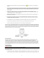
SERVICE MANUAL
LCD Color Television
46RV530U
Rev.1
For Technical Bulletins, Technical Tips, or other information regarding the
service of this model, visit the Toshiba America Consumer Products National
Service Division website at:
www7.toshiba.com
This model is classified as a green product (*1), as indicated by the underlined serial number.
This Service Manual describes replacement parts for the green product. When repairing this
green product, use the part(s) described in this manual and lead-free solder (*2).
For (*1) and (*2), refer to GREEN PRODUCT PROCUREMENT and LEAD-FREE
SOLDER.
© TOSHIBA CORPORATION 2008
IMPORTANT NOTICE
WARNING: Do not modify or alter the information or data provided herein without prior written consent by Toshiba.
Toshiba shall not be liable to anybody for any damages, losses, expenses or costs, if any, incurred in connection with or
as a result of such modification or alteration.
THE INFORMATION OR DATA HEREIN SHALL BE PROVIDED "AS IS" WITHOUT ANY WARRANTY OF ANY KIND, EITHER
EXPRESS OR IMPLIED WARRANTY OF MERCHANTABILITY AND FITNESS FOR A PARTICULAR PURPOSE.
Toshiba shall not be liable for any damages, losses, expenses or costs, if any, incurred in connection with or as a result of
use of any information or data provided herein.
GREEN PRODUCT PROCUREMENT
The EC is actively promoting the WEEE & RoHS Directives that define standards for recycling and reuse of Waste Electrical and
Electronic Equipment and for the Restriction of the use of certain Hazardous Substances. From July 1, 2006, the RoHS Directive will
prohibit any marketing of new products containing the restricted substances.
Increasing attention is given to issues related to the global environmental. Toshiba Corporation recognizes environmental protection
as a key management tasks, and is doing its utmost to enhance and improve the quality and scope of its environmental activities. In
line with this, Toshiba proactively promotes Green Procurement, and seeks to purchase and use products, parts and materials that
have low environmental impacts.
Green procurement of parts is not only confined to manufacture. The same green parts used in manufacture must also be used as
replacement parts.
LEAD-FREE SOLDER
WARNING: This product is manufactured using lead-free solder as a part of a movement within the consumer products industry at
large to be environmentally responsible. Lead-free solder must be used in the servicing and repair of this product.
The melting temperature of lead-free solder is higher than that of leaded solder by 86ºF to 104ºF (30ºC to 40ºC). Use of a soldering
iron designed for lead-based solders to repair product made with lead-free solder may result in damage to the component and or
PCB being soldered. Great care should be made to ensure high-quality soldering when servicing this product especially when
soldering large components, through-hole pins, and on PCBs as the level of heat required to melt lead-free solder is high.
SAFETY INSTRUCTION
WARNING: Before servicing this chassis, read the "Safety Precaution" and "Product Safety Notice" instructions below.
Safety Precaution
WARNING: Servicing should not be attempted by anyone unfamiliar with the necessary precautions on this receiver. The following
are the necessary precautions to be observed before servicing this chassis.
1.
An isolation transformer should be connected in the power line between the receiver and the AC line before any service is
performed on the receiver.
2.
Always disconnect the power plug before any disassembling of the product. It may result in electrical shock.
3.
When replacing a chassis in the cabinet, always be certain that all the protective devices are put back in place, such as
nonmetallic control knobs, insulating covers, shields, isolation resistor-capacitor network, etc.
4.
Always keep tools, product components, etc. away from children as these items may cause injury.
5.
Depending on the model, use an isolation transformer or wear suitable gloves when servicing with the power on.
Disconnect the power plug to avoid electrical shock when replacing parts. In some cases, alternating current is also
impressed in the chassis, so electrical shock is possible if the chassis is contacted with the power on.
6.
Always use the replacement parts specified for the particular model when making repairs. The parts used in products
require special safety characteristics such as inflammability; voltage resistance, etc. therefore, use only replacement parts
1
that have these same characteristics. Use only the specified parts when the
parts list.
mark is indicated in the circuit diagram or
7.
Part mounting and wire routing should be the same as that used originally. For safety purposes, insulating materials such as
isolation tubes or tape are sometimes used and printed circuit boards are sometimes mounted floating. Also make sure that
wiring is routed and clamped to avoid parts that generate heat or use high voltage. Always follow the manufactures wiring
routes / dressings.
8.
Always ensure that all internal wirings are in accordance before re-assembling the external casing after a repair is
completed. Do not allow internal wiring to be pinched by cabinets, panels, etc. Any error in reassembly or wiring can result
in electrical leakage, flame, etc., and may be hazardous.
9.
NEVER remodel the product in any way. Remodeling can result in improper operation, malfunction, electrical leakage, or
flame, which may be hazardous.
10. Always perform an AC leakage current check on the exposed metallic parts of the cabinet such as antennas, terminals,
screw heads, metal overlays, control shafts, etc. to be sure that the set is safe to operate without any danger of electrical
shock before returning the set to the customer.
11. To check leakage current: (After completing the work, measure the leakage current to prevent an electrical shock.)
x
Plug the AC line cord directly into a 120V AC outlet. Do not use an isolation transformer for this check.
x
Use an AC voltmeter having 5000 ohms per volt or more sensitivity in the following manner.
Connect a 1500 ohm 10 watt resistor, paralleled by a 0.15 µF, AC type capacitor, between a known good earth ground (water pipe,
conduit, etc.) and the exposed metallic parts, one at a time. Measure the AC voltage across the combination of 1500 ohm resistor
and 0.15 µF capacitor. Reverse the AC plug at the AC outlet and repeat AC voltage measurements for each exposed metallic part.
Voltage measured must not exceed 0.3 volts rms. This corresponds to 0.2 milliamps AC. Any value exceeding this limit constitutes a
potential shock hazard and must be corrected immediately.
Product Safety Notice
Many electrical and mechanical parts in this chassis have special safety-related characteristics. These characteristics are often
overlooked in a visual inspection. The protection afforded by them cannot necessarily be obtained by using replacement
components rated for higher voltage, wattage, etc. Replacement parts which have these special safety characteristics are identified
in this manual and its supplements. Electrical components having such features are identified by the international hazard symbols
on the schematic diagram and the parts list. Before replacing any of these components, read the parts list in this manual carefully.
The use of substitute replacement parts which do not have the same safety as specified in the parts list may create electrical shock,
fire, or other hazards.
SAFETY INSTRUCTION
WARNING: The metal edges of the LCD module are sharp, handle it with care.
The LCD module can easily be damaged during disassembly or reassembly; therefore, always observe the following precautions
when handling the module.
1.
In the event that the screen is damaged or the liquid crystal (fluid) leaks, do not breathe in, drink, or touch this fluid. Such
actions could cause toxicity or skin irritation. If this fluid should enter the mouth, rinse the mouth thoroughly with water. If the
2
fluid should contact the skin or clothing, wipe off with alcohol, etc., and rinse thoroughly with water. If the fluid should enter
the eyes, immediately rinse the eyes thoroughly with running water.
2.
When attaching the LCD module to the LCD cover, position it appropriately and fasten at the position where the display can
be viewed most conveniently.
3.
Carefully align the holes at all four corners of the LCD module with the corresponding holes in the LCD cover and fasten
with screws. Do not strongly push on the module because any impact can adversely affect the performance. Also use
caution when handling the polarized screen because it can easily be damaged.
4.
If the panel surface becomes soiled, wipe with cotton or a soft cloth. If this does not remove the soiling, breathe on the
surface and then wipe again. If the panel surface is extremely soiled, wipe the panel surface with CRT cleaner sprayed
onto the cloth. Do not spray the cleaner on the panel. Pay attention not to scratch the panel surface.
5.
Leaving water or other fluids on the panel for an extended period of time can result in discoloration or stripes. Immediately
remove any type of fluid from the screen.
6.
Glass is used in the panel construction. Damage can occur if dropped or struck with hard objects.
3
7.
CMOS-LSI circuitry is used in the LCD module, so avoid damage due to static electricity. When handling the module, use a
wrist ground or anchor ground.
8.
Do not expose the LCD module to direct sunlight or strong ultraviolet rays for extended periods.
9.
Do not store the LCD module below the temperature conditions described in the specifications. Doing so could result in
freezing of the liquid crystal, loss of resilience, or other damage.
10. Do not disassemble the LCD module. Such actions could result in improper operation.
11. When transporting the LCD module, do not use packing containing epoxy resin (amine) or silicon resin (alcohol or oxim).
The gas generated by these materials can cause loss of polarity.
4
Entering Service Mode
1.
Set VOLUME to minimum and press MUTE button twice on the remote
control.
Ļ
2.
Press MUTE button again and hold button down.
3.
While holding the MUTE button, press MENU button on TV set.
Ļ
Service Mode display
Selecting the Adjusting Item
Every pressing of CH
or
button in the service mode changes the adjustment items.
or
button will change the value of data in the range from 00H to FFH. The variable range depends on
Adjusting the Data
Pressing of VOLUME
the adjusting item.
Exiting Service Mode
Pressing POWER button to turn off the TV once.
5
Setting Panel Option Data and SET-ID Data
1.
2.
Panel option data is subject to OP4 and OP5.
Enter to service mode and select menu of OP4 or OP5 by pressing CH
or CH
during display of adjustment
menu. After selecting OPT4 or OPT5, press
+ or
- to set OPT4 or OPT5 value as table below.
Whenever using new MAIN PC board to the set, set the SET-ID data according to panel option data.
MODEL
RV530U
SIZE
46
Panel Maker
TOP
Running Change
Samsung
-
TOP
6AH
OPT 4
Running Change
-
OPT 3
60H
OPT 5
00H
SET-ID
93H
Exit from Service Mode
Pressing POWER button to turn off the TV once.
Firmware Update Process
Updating this chassis family is accomplished using an SD card furnished by Toshiba. With the unit operating, insert the card
into the card slot labeled “Service only” located on either the side or back of the instrument. After the card is inserted, simply
follow the step by step update instructions displayed on the screen.
LED BLINK CODES
The green and yellow LED lights on the TV (at the bottom center of the TV) indicate the TV's status, as described below:
Note: If the TV loses A/C power (e.g., a power outage occurs or the power cord is unplugged), when power is restored, the
yellow LED will blink while the TV is booting until the remote control is usable. This is normal and is not a sign of malfunction.
6
7
46RV530U Power Distribution and Plug Layout
1. 24V
2. 24V
3. 24V
4. 24V
5. 24V
6. GND
7. GND
8. GND
9. GND
10. GND
24V Inverter Supplies
LVDS
Inverter
CN60
CN61
CN746
Main
P811A
NU
Charis
1. GND
2. 5V1<
3. GND
4. 12V<
5. 12V<
6. 12V<
7. GND
8. NC
9. NC
10. GND
11. NC
P812A
12. NC
13. 18V Aud.<
14. Aud. GND
P861
P860
P812B
S-Power
CN90
P-Power
P810A
Standby voltages
are in blue italic.
CN91
CN745
1. GND
2. GND
3. GND
4. 5V1>
5. 5V1>
6. 5V1>
7. GND
8. GND
9. GND
1. 12V LCD<
2. 12V LCD<
3. GND
4. GND
5. 3.2V.PWR LCD>
6. NC
7. 2.9V AC Det.<
8. 3.2V PWR Sig.>
9. 3V PWR Prot.<
LED/IR
PCBs
AC In
P802B
8
P803A
Dead
Set
Does
3.2 volts appear at
pin 8 of P810 on the
power board when on/
off is pressed?
Yes
Yes
Does
24 volts appear at
pin 1-5 of P860 on the
power board when on/
off is pressed?
No
No
No
Is
5 volts present at pin 2
of P811 as soon as AC
is applied?
Yes
Suspect the
S power PCB.
No
Suspect the main
PCB.
Do
any LEDs blink after
the on/off switch is
pressed?
Yes
No
Suspect the
P power PCB.
Use
the LED blink
chart to help
diagnose the
problem.
Is
3 volts present at
Pin 9 of P810 as soon
as AC is applied?
No
Yes
Is
2.9 volts present at
pin 7 of P810 as soon
as on/off is
pressed?
Yes
Suspect the main
PCB.
9
*** Contact Toshiba at
www7.tacp.com for
warranty authorization
If the LCD Control
Board is available, try
it. If this does not help,
replace the LCD
display panel. ***
Picture
Problems
YES
NO
Does
the back light function
normally when the unit
is turned on?
YES
Is
the screen discolored
or does it have streaks
or dark areas with no
signal input?
YES
NO
When
the input button
is pressed on the
receiver or remote, is
the on screen display
clear and
normal?
Troubleshoot for
backlight problelms.
(P)* - 46 and 52 inch RV models
contain a P-power supply module.
Replace
the Main
Module.
NO
This signal viewed from
LVDS connector
referencing cold ground.
Examples
NO
Using an
oscilloscope, can an
LVDS signal be
detected at CN60 on
the Main PCB?
YES
Suspect the LCD
Control board.
10
Backlight
Problems
NO
(P)* - 46 and 52 inch
RV models contain a Ppower supply module.
Is
24 VDC present
at pins 1 through 5 of
P860 and P861 when
the unit is turned
on?
NO
Replace the
(P)* Power
supply
module.
NO
Does the back light
function and then turn
off?
YES
If it is
available, try one or
both CCF inverters. If
this does not help,
replace the LCD
display. ***
YES
Is 12VDC
present at pins 1
and 2 of P810A when
the unit is
turned on?
YES
*** Contact Toshiba at
www7.tacp.com for
warranty authorization
YES
If it is
available, replace the
display T-Control PCB.
If it is not available,
replace the LCD display.
***
YES
If
LVDS connector
CN60 is unplugged, Is
12VDC present at pins 1
and 2 of P810A when
the unit is turned
on?
NO
11
Is 3.2VDC
present at pin 5 of
P810A when the unit is
turned on?
NO
Suspect the
main module.
Sound
Problems
Distorted
Is there no sound or is
the audio distorted?
No Sound
NO
NO
Suspect the
(S)* power
supply
module.
Is 18VDC
present at pin 13 of
P811A when the unit is
turned on?
*P811A is located on
the “S” power supply
in the 46 and 52inch
models.
If the
input selection is
changed, does audio
appear?
YES
Problem
solved.
YES
Replace the
Main module
12
PARTS LIST
Precaution
WARNING: BEFORE SERVICING THIS CHASSIS, READ THE "X-RAY
RADIATION PRECAUTION" FOR DIRECT VIEW CTV ONLY, "SAFETY
PRECAUTION" AND "PRODUCT SAFETY NOTICE" OF THIS MANUAL.
CAUTION: The international hazard symbols " " in the schematic diagram
and the parts list designate components which have special characteristics
important for safety and should be replaced only with types identical to
those in the original circuit or specified in the parts list.
The mounting position of replacements is to be identical with originals.
Before replacing any of these components, read carefully the SAFETY
PRECAUTION and PRODUCT SAFETY NOTICE.
Do not degrade the safety of the receiver through improper servicing.
Note:
z
z
The part number must be used when ordering parts, in order to assist in processing, be
sure to include the Model number and Description.
The PC board assembly with
production.
mark is no longer available after the end of the
13
Location
**B001
A201
A401
A420
A421
A422
K902
MZ01
P801
U01A
U02A
U03AS
U04A
U04B
W661
Y102
Part No.
75011245
75011247
75011248
75010936
75010935
75010937
75010932
75011246
75002678
75012805
75011608
75012466
75010926
75010927
75010928
75010933
Description
DISPLAY , LTA460HB07
FRONT BEZEL ASSY 46RV530U, FRONT
BACK COVER ASSY 46RV530U, BACK COVER
LEG STAND LEG ASSY, STAND LEG ASSY 42RV500
BASE BASE ASSY, BASE ASSY 42RV500
CASTOR/LEG TOOL SET, TOOL SET
REMOCON HAND UNIT, CT-90302
WIRE HARNESS, LVDS
POWER CORD, INQ2682(1)
PC BOARD ASSY, PE0564A1,P-POWER
PC BOARD ASSY, PE0563A1, S-POWER, 46RV530U
PC BOARD ASSY, PE0541A(46RV530U), MAIN
PC BOARD ASSY, PE0548C1, LED
PC BOARD ASSY, PE0548C2, REMOTE
SPEAKER ASSY 35X160 8-OHM 10W, SPK-1504AM
MANUAL, OWNERS MANUAL E/F
p
for warrantyy authorization
** Contact Toshiba at www7.tacp.com
14
Comments
LCD Panel
Cabinet Front
Cabinet Back
Stand Leg
Base
Castor tool and screws
Remote Control
LVDS Cable
AC Cord
Power PCB
Sub-Power PCB
Main PCB
LED PCB
Remote PCB
Speaker
Owners Manual
TOSHIBA CORPORATION
1-1, SHIBAURA 1-CHOME, MINATO-KU, TOKYO 105-8001, JAPAN