1
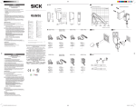
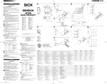
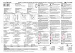
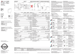
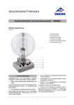
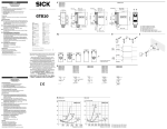
Betriebsanleitung • Operating instructions Instructions de service • Instrucciones de servicio TECHNISCHE DATEN | TECHNICAL DATA | DONNÉES TECHNIQUES | DATOS TÉCNICOS (TYP.) FR 25 -RGO-PS-xxx A) -RGO-NS-xxx A) -RGO2-PS-xxx -RGO2-NS-xxx D Schalt- NPN GB Switching ausgang Q Reichweite (RW) 2) Lichtart Betriebsspannung +UB 3) FR 25-RGO* FR 25-RGO2 Leerlaufstrom I0 PNP Portée (RW) 2) Alcance (RW) 2) 0,5 ... 2 m Type de lumière Tension d’alimentation +UB 3) Tipo de luz Tensión de servicio +UB 3) LED commutation Q conmutación Q NPN Courant de sortie Ie Corriente de salida Ie ≤ 100 mA Steuereingang IN 4) Control input IN 4) Entrée de contrôle IN 4) Entrada de control IN 4) Werkseinstellung Configuration d’origine Ajuste de fábrica Factory setting D ausgenommen Typen 1) GB except for types Fx 25...-M3M/-M4M Fx 25...-M3M/-M4M 2) 2) Bezugsmaterial Reference material Reflektor R5L reflector R5L 3) max. 10% Restwelligkeit, 3) max. residual ripple innerhalb UB, ~50Hz/100Hz 10%, within UB, approx. 50Hz/100Hz 4) 4) siehe Grafik I see illustration I +UB= Teach-in -UB= open = normal function max. RW, N.O. 1) E F sauf les types excepto tipos Fx 25...-M3M/-M4M Fx 25...-M3M/-M4M 2) 2) Matériau de référence Material de réflecteur R5L referencia reflector R5L 3) Ondulation résiduelle maxi 3) máx. 10% de ondulación 10 % à l’intérieur de UB, env. residual, dentro de UB, aprox. 50Hz/100Hz 50Hz/100Hz 4) 4) voir illustration I véase el gráfico I 1) PNP 10 … 30 V DC ≤ 30 mA 1) * D für transparente Objekte * GB for transparent objects * F pour des objets transparents * E para objetos transparentes E Salida de Courant hors charge I0 Corriente en vacío I0 Ausgangsstrom Ie Reflexionslichtschranke mit Autokollimationsprinzip Retro-reflective light barrier with autocollimation principle Barrière optique sur réflecteur avec principe d’ autocollimation Barra de luz reflectora con el principio de auto-colimación output Q Scanning range (RW) 2) Used light Operating voltage +UB 3) No-load supply current I0 Output current Ie F Sortie de D mit Schaltschwellennachführung A) = Taste verriegelt A) GB Switching threshold control F Poursuite du seuil de commutation A) = button locked = bouton verrouillée E Seguimiento del umbral de conmutación A) = tecla bloqueado 1) 068-14420 18.03.2015-05 www.sensopart.com D SICHERHEITSHINWEISE Vor Inbetriebnahme die Betriebsanleitung lesen. Anschluss, Montage, Einstellung und Inbetriebnahme nur durch Fachpersonal. Kein Sicherheitsbauteil gemäß EU-Maschinenrichtlinie (nicht zum Schutz von Personen geeignet). Einsatz nicht im Aussenbereich. Zur Verwendung mit Typen mit Suffix M3, M3M, M4, M4M: Gerader oder L-förmiger M8 Metallstecker, Anschlusssockel aus R/C (CYJV2). ACHTUNG - Durch Verwendung von Bedienelementen oder Einstellungen sowie Durchführung von Verfahren, die nicht hier angegeben sind, kann es zum Austritt gefährlicher Strahlung kommen. BESTIMMUNGSGEMÄSSE VERWENDUNG Sensor wird zum optischen berührungslosen Erfassen von transparenten und nicht transparenten Objekten eingesetzt. MONTAGE Sensor und Reflektor an geeigneten Haltern befestigen. (Halter s. www.sensopart.com) ANSCHLUSS Stecker spannungsfrei aufstecken und festschrauben. Leitung anschliessen. Es gilt das Anschlussschema (s. Grafik B). Für PNP/NPN gilt (s. Grafik C). Spannung anlegen → LED grün leuchtet. Umschaltung N.O. ↔ N.C. (s. Grafik H; Rückseite). N.O. = Schließer; N.C. = Öffner. JUSTAGE (S. GRAFIK D) Sensor auf geeigneten Reflektor (z.B. R5L, RF-230KL) ausrichten bis gelbe LED erlischt. GB SAFETY INSTRUCTIONS Read operating instructions before start-up. Connection, assembly, setting and start-up only by trained personnel. No safety component according to EU machinery directives (not suited for the protection of personnel). Not for outdoor use. For use with models with suffixes M3, M3M, M4, M4M: Straight or L-shaped M8 metal connector, connector base is made of R/C (CYJV2). CAUTION - Use of Controls or adjustments or performance of procedures other than those specified herein may result in hazardous radiation exposure. INTENDED USE Sensor is used for the optical non-contact detection of transparent and non-transparent objects. ASSEMBLY Attach the sensor and reflector to a suitable fixture. (bracket see www.sensopart.com). CONNECTION Insert plug tension-free and screw it tightly. Connect cable according to the connection diagram (see illustration B). For PNP/NPN (see illustration C). Apply voltage → green LED lights up. Switching N.O. ↔ N.C. (see illustration H; back). N.O. = normally open; N.C. = normally closed. ADJUSTMENT (SEE ILLUSTRATION D) Align sensor to suitable reflector (e.g. R5L, RF-230KL) until yellow LED goes off. A. MASSBILD | DIMENSIONAL DRAWING | PLAN COTES | ESQUEMA DE DIMENSIONES 34 1 1 2 3 4 2.6 3 20 4 = 5 2.6 5 GB F E Yellow LED 1) Button Green LED 2) Receiver axis Emitter axis LED jaune 1) Bouton LED verte 2) Axe de récepteur Axe d’émetteur LED amarillo 1) Tecla LED verde 2) Eje de recepción Eje de emisión 4-pin + 1)Schaltausgangsanzeige | switching output indicator | afficheur sortie de commutation | indicación de salida de conexión 2)Betriebsspannungsanzeige | operating voltage indicator | afficheur tension de service | indicación de tensión de servicio - +UB 1 BN NPN IN 2 WH Q 4 BK -UB 3 BU 5 3 7.5 19.3 M8x1 LED gelb 1) Taste LED grün 2) Empfänger achse 5 Senderachse E INDICACIONES DE SEGURIDAD Antes de la puesta en marcha, lea las instrucciones de servicio. La conexión, el montaje, el ajuste y la puesta en marcha deben correr a cargo únicamente de personal especializado. No es una pieza de seguridad según la directiva de máquinas de la UE (no es adecuada para la protección de personas). No utilice en el exterior. Para el uso con modelos con sufijo M3, M3M, M4, M4M: Connector metálico recto o en forma de L, zócalo de conexión de R/C (CYJV2). ATENCIÓN – El uso de controles o ajustes, así como la realización de procedimientos distintos a los especificados aquí pueden provocar una exposición a la radiación peligrosa. USO DEBIDO El sensor se usa para la detección óptica sin contacto de objetos transparentes y opacos. MONTAJE Conecte el sensor y el reflector en soportes adecuados. (para el soporte véase www.sensopart.com). CONEXIÓN Conecte y atornille el conector cuando no haya tensión. Conecte el cable. Aplique el esquema de conexión (véase el gráfico B). Para PNP/NPN (véase el gráfico C). Aplique la tensión → el LED verde se enciende. Conmutación N.O. ↔ N.C. (véase el gráfico H; reverso). N.O. = contacto de cierre; N.C. = contacto de apertura. AJUSTE (VÉASE EL GRÁFICO D) Oriente el sensor con el reflector adecuado (por ejemplo, R5L, RF-230KL) hasta que el LED amarillo se apague. B. ANSCHLUSS | CONNECTION | RACCORDEMENT | CONEXIÓN 3.2 30.4 34 6.6 7.5 19.3 12 D 20 2 30.4 12 F INSTRUCTIONS DE SÉCURITÉ Lire les instructions de service avant mise en service. Raccordement, assemblage, réglage et mise en service ne doivent être effectués que par du personnel qualifié. Il ne s’agit pas de pièces de sécurité selon les directives européennes en vigueur concernant les machines (inappropriées à la protection de personnes). Nepas utiliser à l’extérieur. Pour une utilisation avec types avec suffixe M3, M3M, M4, M4M : Connecteur métallique droit ou en forme de "L", socle de raccordement en R/C /CYJV2). ATTENTION - L'utilisation de commandes, de réglages ou de consignes autres que ceux spécifiés présente un risque d'exposition dangereuse aux radiations. UTILISATION CONFORME Le capteur est utilisé pour la détection optique des objets transparents et non transparents sans contact. MONTAGE Fixer le capteur et le réflecteur sur des supports adaptés. (support voir www.sensopart.com). RACCORDEMENT Insérer le connecteur hors tension et visser. Connecter le câble selon le schéma de raccordement (voir illustration B). Pour PNP/NPN (voir illustration C). Mettre sous tension → LED verte est allumée. Inversion N.O. ↔ N.C. (voir illustration H; verso). N.O. = ouverture; N.C. = fermeture. AJUSTEMENT (VOIR ILLUSTRATION D) Aligner le capteur sur un réflecteur approprié (p.ex. R5L, RF-230KL) jusqu’a ce que la LED jaune s’éteint. 3.2 3.5 6.5 C. SCHALTART | SWITCHING MODE | TYPE DE COMMUTATION | TIPO DE CONMUTACIÓN PNP N.O. N.C. LED yellow + UB - UB + UB - UB NPN N.C. N.O. D. JUSTAGE | ADJUSTMENT | AJUSTEMENT | AJUSTE LED yellow + UB - UB + UB - UB PNP D EINSTELLUNG GB SETTING F RÉGLAGE E CONFIGURACIÓN Der Sensor verfügt über 3 unterschiedliche Teach-inModi. Reflector-Reflector Teach-in (RTI): ist geeignet für die Detektion von transparenten Objekten. Einstellung erfolgt 2x auf den Reflektor (s. Grafik E). FR 25-RGO: Schaltschwellennachführung aktiv. Dynamic Teach-in (DTI): ist für nahezu jede Anwendung geeignet. Einstellung erfolgt im laufenden Prozess (s. Grafik F). Der Reflektor muß mindestens einmal komplett vom Strahlengang erfasst werden. FR 25-RGO: Schaltschwellennachführung aktiv. Reflector-Object Teach-in (ROTI): ist geeignet für die Detektion von nicht transparenten Objekten. Einstellung erfolgt auf den Reflektor und das Objekt (s. Grafik G). FR 25-RGO: Schaltschwellennachführung inaktiv. WARTUNG SENSOPART-Sensoren sind wartungsfrei. Es wird empfohlen in regelmäßigen Intervallen die optischen Flächen zu reinigen und Verschraubungen und Steckverbindungen zu überprüfen. The sensor has 3 differerent Teach-in modes. Reflector-Reflector Teach-in (RTI): is suited for the detection of transparent objects. The setting is made 2x to the reflector. (see illustration E). FR 25-RGO: Switching threshold control active. Dynamic Teach-in (DTI): is suited for nearly all applications. The setting is performed during the running process (see illustration F). The reflector must be completely exposed to the beam route at least once. FR 25-RGO: Switching threshold control active. Reflector-Object Teach-in (ROTI): is suitable for the detection of non-transparent objects. The setting is made to the reflector and the object (see illustration G). FR 25-RGO: Switching threshold control inactive. MAINTENANCE SENSOPART sensors are maintenance-free. We recommend to cyclically clean the optical surfaces and check the screw connections and plug connections. Le capteur a 3 modes différents d’apprentissage (Teachin). Reflector-Reflector Teach-in (RTI) : est adapté à la détection d’objets transparents. L’alignement a lieu 2x sur le réflecteur (voir illustration E). FR 25-RGO : Poursuite du seuil de commutation activée. Dynamic Teach-in (DTI) : est adapté à presque toutes les applications. L’alignement a lieu durant le processus (voir illustration F). Le chemin des rayons doit saisir le réflecteur au moins une fois dans son intégralité. FR 25-RGO : Poursuite du seuil de commutation activée. Reflector-Object Teach-in (ROTI) : est adapté à la détection d’objets non transparents. L’alignement a lieu sur le réflecteur et sur l’objet (voir illustration G). FR 25-RGO : Poursuite du seuil de commutation inactivée. ENTRETIEN Les capteurs SENSOPART ne demandent aucun entretien. Nous recommandons de nettoyer les surfaces optiques et vérifier les raccordements et les fixations régulièrement. El sensor dispone de 3 modos Teach-in diferentes. Reflector-Reflector Teach-in (RTI): resulta adecuado para la detección de objetos transparentes. El ajuste se realiza dos veces en el reflector (véase gráfico E). FR 25-RGO: Seguimiento del umbral de conmutación activo. Dynamic Teach-in (DTI): adecuado casi para cualquier uso. El ajuste se realiza con el proceso en curso (véase gráfico F). El reflector debe ser captado en su totalidad por el trayectoria de los rayos al menos una vez. FR 25-RGO: Seguimiento del umbral de conmutación activo. Reflector-Object Teach-in (ROTI): resulta adecuado para la detección de objetos no transparentes. La configuración se realiza en el reflector y en el objeto (véase gráfico G). FR 25-RGO: Seguimiento del umbral de conmutación inactivo. MANTENIMIENTO Los sensores SENSOPART no necesitan mantenimiento. Se recomienda limpiar las superficies ópticas a intervalos regulares y comprobar las uniones atornilladas y conexiones. F. DYNAMIC TEACH-IN (DTI) Step 1: During running process press > 3 s 1 Step 2: Teach-in object 2 press > 1 s 3 3 External Teach-in → I. Step 2: Teach-in object press > 1 s ok until green & yellow LED flash at the same time External Teach-in → I. H. UMSCHALTUNG N.O. / N.C. | SWITCHING N.O. / N.C. | INVERSION N.O. / N.C. | CONMUTACIÓN N.O. / N.C. press > 13 s N.O. until green & yellow LED flash alternately green LED flashes yellow LED OFF green LED flashes yellow LED ON wait 10 s wait 10 s press ok N.C. press N.O. ... ok I. EXTERNAL TEACH-IN BN +UB WH IN D Einstellung über Steuereingang IN: Schließ- und Öffnungsdauer analog den jeweiligen Angaben für die Taste. GB Setting via control input IN: Closing and opening times according to the corresponding indications for the button. F Réglage par entrée de contrôle IN : Temps de fermeture et d’ouverture selon l’indication correspondante de la bouton. E Configuración mediante la entrada de control IN: La duración de cierre y apertura es conforme a la indicación correspondiente de la tecla. www.sensopart.com 5 until green & yellow LED flash at the same time External Teach-in → I. press > 3 s 4 press > 3 s ok until green & yellow LED flash at the same time G. REFLECTOR-OBJECT TEACH-IN (ROTI) Step 1: Teach-in reflector Step 2: Teach-in object during running process Änderungen vorbehalten | subject to change | sous réserve de modifications | salvo modificación E. REFLECTOR-REFLECTOR TEACH-IN (STI) Step 1: Teach-in reflector 4 5 6 7 1 cyc le press > 1 cycle ok