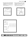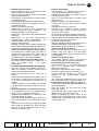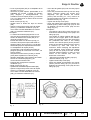
1
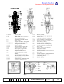
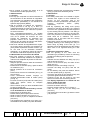
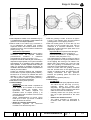
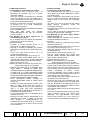
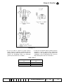
Bopp & Reuther
Sicherheits- und Regelarmaturen
Instrucciones de servicio y
de mantenimiento
Válvulas de seguridad SiC
con carga de muelle
Operating and
Maintenance Instructions
SiC-Safety Relief Valves
Spring Loaded
Tipo SiC 11
Capota abierta
Type SiC 11
open bonnet
Tipo SiC 13
Estándar
Type SiC 13
conventional
Tipo SiC 14
con fuelle de pliegues
Type SiC 14
balanced bellow
Variantes de ejecución:
Options:
- Conexiones roscadas
- Conexiones de brida
- G Estanqueidad al gas
-A
Estanqueidad al gas, puede
ventilarse
-B
Bloqueable
-Thread Connection
-Flange Connection
-G
gastight
-A
packed lifting lever
-B
with test rod
Código de materiales:
Material-Code:
00 acero fundido no aleado 1.0619/WCB
04 acero fundido aleado 1.4408/CF8M
00 Carbon Steel
04 Stainless Steel
1.0619/WCB
1.4408/CF8M
Hoja, sheet,
de, of, de
page
B
A
-
Ahrens
Hauert
Illius
SRE-E
SRE-E
SRE-E
Nombre,n Dep., dep.,
ame,nom
Rev.
hecho,
modif.,
dép.
issued by,
revised by,
30.10.01
29.09.00
27.06.00
Föllmer
Haracska
Ha
SRE-E
SRE-K
SRE
Fecha, date Nombre, name,
Dep., dep.,
Fecha, date
dép.
checked by,
contrôlé par
nom
édité par
modifé par
controlado,
30.10.01
1
09.10.00
27.06.00 N°,No.
15
0-50-00003.4
Bopp & Reuther
Sicherheits- und Regelarmaturen
1/1&1/1/1
1/1/2
1/1/3
1/2
1/3
2/1
2/5/1&2/5/1/1
2/5/1/2
2/5/1/3
2/5/2
2/5/3
2/7
2/8
2/9
2/10
2/12
2/15/1
2/15/2
2/15/3
Fig. 4
Rev.
-AB
Fig. 1
Carcasa / Body
Tubo / Pipe
Brida soldada de revestimiento /
Sleeve Welding Flange
Tubuladura de entrada / Nozzle
Brida / Flange
Campana elevadora / Lifting Bell
Campana elevadora/placa inf. /
Lifting bell/Lower Plate
Husillo / Spindle
Clavija cilíndrica / Socket Pin
Fuelle de pliegues / Bellows
Placa superior / Upper Plate
Junta plana / Gasket
Tampa intermedia / Guide
Casquillo de presión / Guide
Bushing
Clavija cilíndrica / Socket Pin
Plato de muelles / Spring Washer
Capota / Bonnet
Tornillo tensor / Adjusting Screw
Contratuerca /Adjusting Screw Nut
Fig. 2
2/16
2/17
2/18
3/1
3/3/1
3/3/2
3/4
3/7
3/8
3/10
4
5/1
5/2
5/4
5/5
5/6
5/7
5/8
10
Fig. 3
Husillo / Spindle
Tuerca de ventilación / Spindle Nut
Tuerca / Nut
Calota de ventilación / Lifting Cap
Eje de ventilación / Lifting Shaft
Palanca de ventilación / Lifting Lever
Anillo tórico / O-Ring
Pasador de aletas / Tension Pin
Tornillo de cierre / Blanking Plug
Tornillo bloqueador / Gagging Bolt
Disco / Disc
Seguro de disco / Disc Retainer
Junta plana / Gasket
Junta plana / Gasket
Tornillo cilíndrico / Socket Head Screw
Bola / Ball
Tornillo cilíndrico / Socket Head Screw
Tornillo limitador de carrera /
Lift Limiting Screw
Muelle / Spring
Fig. 5
Nr.,
No.
0-50-00003.4
Blatt,
sheet,
page
2
von,of,
de
15
Bopp & Reuther
1. Funcionamiento
1.1 Las válvulas de seguridad soplan luego que
la presión del muelle que se ejerce sobre el
disco (4) es superada por la presión del medio.
La campana elevadora (2/1;2/5/1;2/5/1/1) sirve
como ayuda de elevación.
1.2 Las tolerancias para la presión de abertura y
de cierre están en el margen de las normas
válidas: ASME Sec. VIII, AD y TRD.
1.3 El fuelle de pliegues (2/5) en la válvula tipo
SiC14 prohibe la entrada del medio en la
cámara del muelle protegiéndolo contra
corrosión.
1.4 La contrapresión efectiva es compensada
por el fuelle de pliegues (2/5) porque la
superficie central del disco (4) y la superficie
eficaz del fuelle de pliegues (2/5/2) son iguales
y la cámara de la capota (2/15/1) comunica
con la presión atmosférica.
Así la contrapresión externa no tiene influencia
en la presión de reacción de la válvula.
1.5 Una rotura del fuelle de pliegues (2/5) en la
versión cerrada significa que la presión de
reacción se aumenta por la mitad de la presión
externa efectiva.
1.6 La carrera está delimitada por un tope (ver fig. 13).
2. Transporte y condiciones de entrega
Transportar la válvula posiblemente sin
sacudidas ni vibraciones. Las válvulas de
seguridad suministradas por la Bopp &
Reuther han sido controladas en fábrica y
ajustadas a la presión de reacción deseada y
selladas con plomo. Una placa con el
estampado NB o la contraseña de componente
constructivo del TÜV está fijada en el costado
de la capota (2/15/1). En esta placa se indican
también la presión de reacción y el número de
encargo de la fábrica (n° WA). En el control en
nuestra fábrica, p.ej. por el TÜV etc., este
control está también documentado por un
estampado.
2.1 El barnizado de la fundición de acero no
aleado (1.0619/WCB) se realiza con pintura de
polvo de zinc. En cima de este se puede
aplicar cualquier otra pintura. Las válvulas de
acero fundido no aleado (1.4408/CF8M) no son
barnizadas.
Rev.
-AB
Nr.,
No.
1. Operation
1.1 Safety valves blow off as soon as the spring
force acting on the disc (4) is surmounted by
the medium pressure. In this connection the
lifting bell (2/1;2/5/1;2/5/1/1) operates as lifting
assistance.
1.2 The tolerances for the opening and closing
pressure are within the range of the given
prescriptions, ASME Sec. VIII, AD and TRD.
1.3 The bellows (2/5) in the valve type SiC14
avoids the entering of the medium into the
spring chamber and protects against corrosion.
1.4 The existing back pressure is balanced by
the bellows (2/5) such that the average disc
face (4) and the effective area of the bellows
(2/5/2) are the same and the bonnet chamber
(2/15/1) is connected with atmospheric
pressure.
Thus, the superimposed back pressure has no
influence on the set pressure of the valve.
1.5 A rupture of the bellows (2/5) in case of the
closed execution means that the set pressure
increases by the amount of the existing
superimposed back pressure.
1.6 The lift is limited by a stop (see figure 13).
2. Transport, Delivery Condition
The valves shall be transported to the site as
shock- and shakeproof as possible.The safety
valves delivered by Bopp & Reuther have been
tested in the factory, adjusted to the desired set
pressure and leaded. A label with the NBstamp or the TÜV type approval, respectively,
is fastened at the connecting flange of the
bonnet (2/15/1) to the body (1/1/1) above the
set screw (1/1/12). The set pressure and the
works order number (w. o. no.) are also
indicated on this label.In case of an inspection
in our factory, f. i. by TÜV etc., this test is also
identified by application of a stamp.
2.1 The painting of unalloyed cast steel
(1.0619/WCB) is made with inorganic zinc
colour. Afterwards, every further colour painting
can be applied. Valves made of alloyed
material (1.4408/CF8M) do not get any
painting.
0-50-00003.4
Hoja,
sheet,
page
3
de,of,d
e
15
Bopp & Reuther
3. Montaje
Limpiar las partes de la instalación que se van
a segurar antes del montaje de la válvula.
Quitar las calotas de protección en la entrada y
la salida de la válvula, pero sólo mismo antes
del montaje de la válvula o un ensayo.
Atención: El asiento en este válvula
ha sido lapeado a un nivel óptico y por
eso puede facilmente ensuciarse por
suciedad o partículas. Si se utiliza la
válvula para fines de ensayo antes de
la instalación final, hay que secar
cuidadosamente las partes interiores
de la válvula después de los ensayos y
después volver a ponerse las calotas
protectoras.
El dispositivo de prueba de la válvula
así como el fluido de prueba (gas, aire)
deben estar absolutemente limpios.
Debe asegurarse que ni la unidad de
prueba ni la entrada de válvula sean
contaminadas
con
suciedad
o
partículas antes de realizarse un
ensayo o la instalación final de la
válvula.
3.1 ¡Montar la válvula de seguridad con
husillo (2/16;2/5/1/2) en posición vertical!
El montaje y el desmontaje de la válvula en la
instalación o en el caballete de ensayo debe
realizarse sólo al aplicar una llave bifurcada en
la tubuladura de entrada (1/2). No se debe dar
vuelta a la parte superior de la válvula o a la
carcasa (1/1; 1/1/1), tampoco para tal vez
alinear la tubería de salida, pues podría
aflojarse la unión roscada entre la carcasa y la
tubuladura de entrada podiendo producirse con
esto fugas de la válvula para dentro y para
fuera.
3.2 Para el transporte está asegurada la palanca
de ventilación (3/3/2). Hay que quitar este
seguro sólo después del montaje y volver a
ponerlo después de un ensayo y antes de otro
transporte.
3.3 Hay que disponer la tubería de soplado de
modo que facilite la corriente En caso de
líquidos o medios que producen condensado,
la tubería debe obtener una inclinación al salir
de la válvula. En la posición más baja de la
tubería hay que poner un desagüe
suficientemente dimensionado o un tubo de
purga
de
condensado.
Al
producirse
contrapresión en la tubería de soplado, la
descarga debe automaticamente volver a
cerrarse después de purgar el condensado.
Rev.
-AB
Nr.,
No.
3. Installation
The system elements to be protected have
to be cleaned before mounting the valve.
Remove protective caps at the inlet and
outlet of the valve. This, however, shall only
be done immediately before mounting or
testing the valve.
ATTENTION: The seat in this valve
are lapped to optical flatness and can
easily be damaged by dirt or other
particles. If removed for test, dry valve
interior and reseal until just before
installation. Test equipment and test
gas or air must be absolutely clean.
Care must betaken to ensure that
neighter test equipment nor valve inlet
contains any dirt particles before testing
or installing this valve.
3.1 Mount the safety valve with spindle
(2/16;2/5/1/2) in perpendicular position !
Mounting and dismounting of the valve within
the system or on the test stand may only be
performed by applying a fork wrench at the
inlet nozzle (1/2). It is not allowed to turn at the
valve top or at the body (1/1; 1/1/1), even not
for a possible centering of the outlet pipe as
otherwise the screwed connection between the
body and the nozzle risks to loosen and, thus,
the valve might become leak inside and
outside.
3.2 As transport protection the lifting lever (3/3/2)
is wired. This wire may only be removed after
the installation and must be applied again after
a possible test and new transport.
3.3 The discharge pipe has to be arranged in
favourable flow direction. In case of liquids and
media generating condensate the pipe must
have a slope away from the valve. At the
deepest place of the pipe a sufficiently
dimensioned drain or a condensate discharge
has to be provided. If back pressure is built up
in the discharge pipe the discharge has to
close again automatically after having drained
the condensate.
0-50-00003.4
Hoja,
sheet,
page
4
de,of,d
e
15
Bopp & Reuther
3.4 Las válvulas de seguridad del tipo SiC14
tienen una perforación roscada "b" en la calota
(2/15/1) (ver fig. 2 y 3). A través de esta
perforación roscada se ventila la cámara de la
calota (2/15/1), esto es, es unida con presión
atmosférica. Para los medios tóxicos
fácilmente inflamables se puede enroscar un
tubo para purgar el material de una fuga. A
este tubo puede montarse una posibilidad de
prueba (p.ej. grifo de cierre y manómetro) para
detectar una fuga del fuelle de pliegues (2/5).
Atención:
El tubo enroscado no debe penetrar en la
cámara interior de la capota ya que esto
puede bloquear el muelle.
Evite absolutamente la presión en la calota
(2/15/1) porque la presión de reacción
aumentaría más aquella presión en la calota.
Controle regularmente el fuelle de pliegues
(2/5).
4. Ajuste de la presión de reacción
La válvula de seguridad está asegurada con
plomo contra un desajuste no autorizado de la
presión de reacción. Un reajuste de la presión
de reacción debe ser hecho sólo por personal
instruido y responsable en la presencia de un
perito (consulta con el fabricante).
4.1 La presión de reacción puede ajustarse en
los límites definidos por la Bopp & Reuther SR
GmbH.
Modo de proceder:
- Hay que quitar el precinto entre la capota
(2/15/1) y la calota (3/1).
- Desenroscar los tornillos (5/5) y quitar la calota
de ventilación (3/1).
- Aflojar la contratuerca (2/15/3).
- Al girar el tornillo tensor (2/15/2) en sentido
horario se aumenta la presión de reacción, al
girar en sentido opuesto se la reduce.
Advertencia importante: Para evitar una
danificación de la superficie de asiento
(4;1/1/3) o el fuelle de pliegues (2/5)
(torsión), al ajustar el tornillo tensor
(2/15/2), hay que sujetar el husillo (2/16) en
la tuerca (2/18).
- Después de terminar el ajuste de la presión
apretar la contratuerca (2/15/3).
- Montar la calota de ventilación (3/1), utilizando
un sello nuevo (5/4).
- Hay que observar que el precinto entre la
calota de ventilación (3/1) y la capota (2/15/1)
vuelva a ser puesta.
- Al realizarse la homologiación en nuestra
fábrica por un perito reconocido, el control
queda documentado mediante estampado.
Rev.
-AB
Nr.,
No.
3.4 Safety valves of the type SiC14 have a
threaded boring "b" (s. figure 2 and 3) in the
bonnet (2/15/1). Via this threaded boring the
bonnet chamber (2/15/1) is aerated i. e.
connected to atmospheric pressure. In case of
toxic, easily inflammable media a pipe may be
screwed to discharge a leakage. To this pipe a
testing possibility (f. i. isolating valve and
manometer) can be mounted in order to detect
leakage of the bellows (2/5).
Attention: The screwed pipe must not
protrude into the bonnet inside as this might
block the spring.
The building up of pressure within the
bonnet (2/15/1) must absolutely be avoided
because otherwise the set pressure would
increase by this built-up pressure.
A regular control of the bellows (2/5) must
be carried out.
4. Adjustment of the Set Pressure
The safety valve is leaded against
unauthorized modification of the set pressure.
An adjustment of the set pressure may only be
carried out by specialist and responsible
personnel with the presence of an expert
(contact the manufacturer).
4.1 The set pressure may be adjusted within
certain limits according to the definition of Bopp
& Reuther SR GmbH.
Procedure:
- The lead between the bonnet (2/15/1) and the
cap (3/1) must be removed
--Screw out the screws (5/5) and take of the
lifting cap (3/1)
- Release the adjusting screw nut (2/15/3)
- Turning of the adjusting screw (2/15/2)
clockwise increases the set pressure, turning in
opposite direction decreases the set pressure
Important Note: In order to avoid a
damage of the seat area (4;1/1/3) or the
bellows (2/5) (torsion) the spindle (2/16)
has to be held at the nut (2/18) when
adjusting the adjusting screw (2/15/2).
- After the pressure adjustment has been
terminated tighten the counter nut (2/15/3).
- Mount the lifting cap (3/1), when doing this
utilize new gasket (5/4)
- Mind that the leading between the lifting cap
(3/1) and the bonnet (2/15/1) is applied again
- In case of inspection in our factory by an
authorized expert the test is marked with a
stamp
0-50-00003.4
Hoja,
sheet,
page
5
de,of,d
e
15
Bopp & Reuther
4.2 Al cambiar la presión de ajuste, B & R
suministrará el muelle apropiado (10).
5. Mantenimiento
5.1 Control
5.1.1 Hay que comprobar en ciertos intervalos el
funcionamiento de las válvulas de seguridad.
(nos referimos a la regulación para recipientes
bajo presión (DruckbehV) o a la directiva de
aparatos bajo presión (DGRL).
5.1.2 Al accionar la palanca de ventilación
(3/3/2) (dirección A ver fig. 3), el disco (4)
queda descargado de modo que el disco (4) se
levanta de su asiento por causa de la presión
de servicio efectiva.
Este levantamiento/ventilación es posible
cuando la presión de servicio es por lo menos
75% de la presión de reacción. En este
proceso de ventilación es suficiente una
pequeña carrera de la válvula. Hay que
observar que la presión de servicio sea inferior
a la presión de cierre de la válvula.
5.1.3 Si las válvulas de seguridad tienen fugas,
los cuerpos ajenos pegados a la superficie de
junta pueden soplarse al levantar el disco (4).
Si con esto no se alcanzara suficiente
obturación, en la siguiente pausa del servicio
se deberán rectificar las superficies de junta.
5.2 Rectificado de los asientos de válvula
5.2.1 Para rectificar el asiento de válvula es
posible el desmontaje mediante una ayuda de
retención sin desajustar la presión de reacción.
Modo de proceder:
- Aflojar el precinto entre la calota de ventilación
(3/1) y la capota (2/15/1).
- Desenroscar los tornillos (5/5) y quitar la calota
de ventilación (3/1).
- Marcar posición de la tuerca de ventilación
(2/17).
- Desenroscar la tuerca de ventilación (2/17) y la
tuerca (2/18).
- Como herramienta auxiliar, empujar un
casquillo distanciador sobre el husillo (2/16)
(ver fig. 6).
- Enroscar la tuerca (2/18) sobre el husillo (2/16)
hasta que apriete contra el casquillo
distanciador.
- Girar la tuerca (2/18) con llave anular/bifurcada
2 hasta 3 vueltas más.
- El ajuste del muelle está retenido y el disco
se ha levantado de su asiento.
- Desenroscar los tornillos (5/7).
- Retirar toda la parte superior de la válvula.
- Quitar el seguro del disco (5/1) (ver fig. 7).
- Sacar el disco (4) de la campana elevadora
(2/1;2/5/1).
- Las superficies de obturación en el disco (4) y
la tubuladura de entrada (1/2) están liberadas.
Rev.
-AB
Nr.,
No.
4.2 When changing the set pressure the suitable
spring (10) has to be defined by B & R.
5. Maintenance
5.1 Control
5.1.1 Safety valves have to be tested in regular
intervals with regard to their readiness for
service. (In this connection refer to the
pressure vessels specification (DruckbehV) or
pressure
equipment
device
(PED),
respectively.
5.1.2 By operating the lifting lever (3/3/2)
(direction A see figure 3) the disc (4) is relieved
to that the disc (4) detaches the seat supported
by the existing service pressure. This lifting is
possible if the service pressure is at least 75%
of the set pressure. For this lifting operation a
small valve lift is sufficient. The service
pressure has to be lower than the closing
pressure of the valve.
5.1.3 If safety valves are leak foreign substances
possibly adhering to the sealing face may be
blown away by lifting of the disc (4). If a
tightness cannot be obtained by this the sealing
faces have to be regrinded during the next
stop.
5.2 Grinding of the Valve Seats
5.2.1 For grinding of the valve seat the
dismanthing is possible by means of a blocking
aid without modifying the set pressure.
Procedure:
- Release the lead between the lifting cap (3/1)
and the bonnet (2/15/1).
- Screw out the screws (5/5) and take off the
lifting cap (3/1)
- Mark the position of the lifting nut (2/17).
- Unscrew the lifting nut (2/17) and the nut
(2/18).
- As an auxiliary tool push the distance sleeve
over the spindle (2/16) (s. figure 6).
- Screw the nut (2/18) on the spindle (2/16) until
it presses against the distance sleeve.
- Continue to turn the nut (2/18) by two until
three turns with a fork wrench/ring wrench.
- The Spring Adjustment is Locked and the
Disc is Lifted off the Seat.
- Screw out the screws (5/5).
- Remove the whole valve top.
- Remove the disc retainer (5/1) (s. figure 7).
- Take the disc (4) out of the lifting bell
(2/1;2/5/1).
- The sealing faces at the disc (4) and the nozzle
(1/2) are free.
0-50-00003.4
Hoja,
sheet,
page
6
de,of,d
e
15
Bopp & Reuther
Fig. 7
Fig. 6
5.2.2 El lapeado se realiza, como mostrado en fig. 8 y
9, mediante discos de lapeado y pasta abrasiva de
grano fino o en una máquina lapeadora.
5.2.3 La vuelta "e" en el disco (4) y el escalón "f"
en la tubuladura de entrada (1/2) pueden
repasarse hasta una medida mínima. Si esta
medida es menos, será necesario cambiar las
piezas (ver fig. 10).
Advertencia importante:
Las danificaciones mayores del asiento deben
eliminarse antes del lapeado mediante
procesamiento
mecánico
o
utilizando
esmeriladores gruesos (ver punto 5.3.1).
El lapeado manual se realiza al girar a derecha y a
izquierda con ligera presión, en lo que es necesario
aprovecharse de la superficie mayor posible del
disco lapeador. El disco lapeador debe siempre
cubrir por completo la superficie del asiento. El
rectificado está terminado cuando la superficie del
asiento ya no tiene daños.
Limpiar los asientos después del rectificado.
Para acabar el pulido, aplicar pasta pulidora y
kerosene en el reverso no utilizado del disco
lapeador y pulir con movimientos rotativos y
con suave presión. Quitar la pasta pulidora y
controlar las superficies del asiento.
5.2.4 Utilizar nuevas juntas (5/2;5/4).
5.2.5 Ensamblaje
ATENCIÓN:
- Retener el ajuste del muelle e implantar la
parte superior de la válvula en la carcasa
(1/1;1/1/1), apretar los tornillos (5/7)
igualmente en sentido diagonal. La
hendidura entre la capota (2/15/1) y la
carcasa debe tener el mismo ancho en toda
la circunferencia.
- Aflojar cuidadosamente la tuerca (2/18)
hasta que el disco (4) vuelva a sentarse
sobre el asiento de válvula.
- ¡Quitar el casquillo distanciador!
- Ensamblaje
siguiente
en
secuencia
invertida como descrito bajo 5.2.1.
Rev.
-AB
Nr.,
No.
5.2.2 The grinding is made, as shown in figures
8 and 9, with lapping discs and fine-grained
grinding paste or on a lapping machine.
5.2.3 The turned groove "e" at the disc (4) and
the heel "f" at the nozzle pipe (1/2) may be
reworked to a minimum dimension. If this
dimension is fallen below the parts have to be
replaced (s. figure 10).
Important Note: Important seat damages
have to be removed before lapping by
mechanical treatment f. i. by utilizing rough
abrasive cloth (see point 5.3.1).
The hand-lapping is made by turning to and fro
with light pressure the largest possible surface
of the lapping disc having to be utilized. The
lapping disc must always fully cover the seat
area. The grinding is terminated if the seat
area does not show damages anymore.
Clean the seats after the grinding. Repolish
with the unused back of the lapping disc by
means of polishing paste and petroleum with
rotating movements and light pressure.
Remove the polishing paste and check the
seat areas.
5.2.4 Utilize new gaskets (5/2;5/4).
5.2.5 Assembly
ATTENTION:
- In case of locked spring adjustment Insert
The valve top into the body (1/1;1/1/1),
uniformly tighten the screws (5/7)
diagonally. The gap between the bonnet
(2/15/1) and the body must have the same
width on the whole circumference.
- Carefully loosen the nut (2/18) until the
disc (4) is again positioned on the valve
seat.
- Remove the distance sleeve !
- The further mounting is performed in
reversed order than that described in
5.2.1.
0-50-00003.4
Hoja,
sheet,
page
7
de,of,d
e
15
Bopp & Reuther
5.2.6 La presión de reacción puede desajustarse
por el trabajo posterior en el asiento. Debería
controlarse y de nuevo ajustarse si necesario
(ver punto 4).
Después de terminar estos trabajos, poner el
seguro de precinto entre la capota (2/15/1) y la
calota de ventilación (3/1).
5.2.6 The set pressure may perhaps change
because of the reworking of the seat. It has to
be checked and adjusted again if necessary
(see par. 4).
After having terminated these operations the
leaded seal between the bonnet (2/15/1) and
the lifting cap (3/1) has to be applied.
Fig. 9
Fig. 8
Fig. 10
Rev.
-AB
Nr.,
No.
0-50-00003.4
Hoja,
sheet,
page
8
de,of,d
e
15
Bopp & Reuther
5.3 Desmontaje de válvula
Para cambiar el muelle o la limpieza de las
piezas individuales, proceda así:
- Aflojar el precinto entre la calota de ventilación
(3/1) y la capota (2/15/1).
- Desenroscar los tornillos (5/5) y quitar la calota
de ventilación (3/1).
- Marcar posición de la tuerca de ventilación (2/17).
- Desenroscar la tuerca de ventilación (2/17) y la
contratuerca (2/18).
- Aflojar la contratuerca (2/15/3).
- Desenroscar el tornillo tensor (2/15/2) en
sentido antihorario hasta notificarse una
descarga notable por el muelle (10).
- Desenroscar los tornillos (5/7) diagonalmente
opuestos.
- Desenroscar los dos otros tornillos (5/7)
alternadamente hasta desestablecer una
eventual pretensión restante del muelle.
- Quitar la capota (2/15/1).
- Mediante el husillo (2/16) pueden extraerse por
arriba todas las piezas internas de la carcasa (1/1).
- Desmontar el seguro del disco (5/1) (ver fig. 7).
Versión de fuelle de pliegues SiC14, d012,2:
- Al desenroscar el husillo (2/16) del fuelle de
pliegues (2/5) tipo SiC14, debe fixarse sólo la
campana elevadora/placa inferior (2/5/1)
(ninguna torsión en el fuelle de pliegues).
Versión de fuelle de pliegues SiC14, d017:
El husillo (2/5/1/2) forma una unidad con el
fuelle de pliegues (2/5) y no puede
desmontarse.
5.3.1 Desmontaje de la tubuladura de entrada (1/2)
Esto por ejemplo es necesario cuando los
daños en el asiento están tan grandes que es
necesario un acabado mecánico.
- Quitar la parte inferior de la válvula de la
tubería.
- Desenroscar la tubuladura de entrada (1/2) de
la carcasa (1/1). Hay que fixar la carcasa (1/1)
a la brida cuadrangular (conexión de la
capota).
- Trabajo mecánico en la tubuladura de entrada
(1/2) es posible (procesado posterior max. ver
fig. 10).
5.3.2 Desmontaje de la ventilación (ver fig. 5)
Si la ventilación en el eje de ventilación tiene
fugas, hay que cambiar el anillo tórico.
- Golpear fuera el pasador con aletas (3/7) con
el mandril (diámetro 2,5mm).
- Extraer el eje de ventilación (3/3/1-3/3/2) de la
calota de ventilación (3/1), desmontar el anillo
tórico.
- Antes de un nuevo montaje limpiar las piezas,
sobre todo las superficies de junta del anillo
tórico en el eje de ventilación (3/3/1) y en la
calota de ventilación (3/1).
Rev.
-AB
Nr.,
No.
5.3 Valve Disassembly
The procedure for replacing the spring or
cleaning the components is as follows:
- Release the lead between the lifting cap (3/1)
and the bonnet (2/15/1).
- Screw out the screws (5/5) and take off the
lifting cap (3/1)
- Mark the position of the lifting nut (2/17).
- Unscrew the lifting nut (2/17) and the counter
nut (2/18).
- Release the counter nut (2/15/3).
- Unscrew the adjusting screw (2/15/2)
counterclockwise until a sensible relieving by
the spring (10) is stated.
- Screw out two diagonally opposite screws (5/7)
- Screw out the two other screws (5/7) uniformly
and alternately until a possibly existing residual
prestress of the spring is relieved
- Lift off the bonnet (2/15/1).
- With the spindle (2/16) all internal parts may be
removed upwards out of the body (1/1)
- Disassemble the disc retainer (5/1) (see fig. 7).
Bellows design SiC14, d0 12.2:
- When screwing the spindle (2/16) out of the
bellows (2/5) type SiC14, only the lifting
bell/lower plate (2/5/1) may be fixed (no torsion
on the bellows).
Bellows design SiC14, d0 17:
The spindle (2/5/1/2) forms a unit with the
bellows (2/5) and may not be disassembled
5.3.1 Dismounting of the Nozzle (1/2)
This is necessary, f. i., if the damages at the
seat are so important that a mechanical
treatment is required.
- Remove the valve bottom from the pipe.
- Screw the nozzle (1/2) out of the body (1/1).
In this connection the body (1/1) has to be
fastened at the square flange (bonnet
connection).
- The mechanical treatment at the nozzle (1/2)
can be carried out (max. rework see figure 11).
5.3.2 Dismounting of the Lifting (s. Figure 5)
If the lifting is leak at the lifting shaft the O-ring
has to be replaced.
- Drive the tension pin (3/7) out with a drift
(diameter 2.5mm).
- Draw the lifting shaft (3/3/1-3/3/2) out of the
lifting cap (3/1), dismount the O-ring.
- Before remounting the parts have to be
cleaned; this is particularly true for the O-ring
sealing faces at the lifting shaft (3/3/1) and in
the lifting cap (3/1).
0-50-00003.4
Hoja,
sheet,
page
9
de,of,d
e
15
Bopp & Reuther
5.4 Montaje de válvula
5.4.1 Montaje de la tubuladura de entrada
La obturación entre la carcasa (1/1) y la
tubuladura de entrada (1/2) es un borde
obturador metálico.
Antes de enroscar la tubuladura de entrada
(1/2) en la carcasa (1/1) hay que cuidar que en
las dos partidas las roscas y las superficies de
junta sean absolutamente limpias.
Durante el proceso de enroscar hay que fixar
la carcasa (1/1) a la brida cuadrangular
(conexión de la capota).
El par de apriete para la tubuladura de entrada
(1/2) es 400Nm +10%.
Esto
vale
para
todas
las
válvulas
independientemente del tipo de conexión
(roscas o bridas).
5.4.2 Montaje de la parte superior de la
válvula SiC13 (ver fig. 1)
En el montaje hay que utilizar las siguientes
obturaciones nuevas (2/7;5/2;5/4).
Modo de proceder:
- Enchufar la clavija cilíndrica (2/10) en la
perforación de husillo prevista (2/16).
- Empujar la campana elevadora (2/1) desde
arriba sobre la clavija (2/10) hasta el tope (ver
fig. 11).
- Poner bola (5/6) entre el disco (4) y la
campana elevadora (2/1).
- Montar el seguro del disco (5/1) (ver fig. 12)
- Cubrir el husillo (2/16) desde arriba con el
casquillo de presión (2/9) y la tapa intermedia
(2/8) (diámetro exterior pequeño hacia abajo).
- Medir carrera (ver fig. 13).
5.4.2.1 Fijar husillo en posición de carrera max.,
montar parte superior en la carcasa.
- Poner la junta plana (2/7) en el adaptador de la
capota (2/15/1) y enchufar las piezas antes
nombradas juntas con los platos de muelle (2/12) y
el muelle (10) en el grupo premontado capota
(consisten en 2/15/1;2/15/2; 2/15/3). El tornillo tensor
(2/15/2) está desenroscado tanto para arriba que el
plato de muelle queda por arriba en la capota.
- Como herramienta auxiliar, empujar un
casquillo distanciador sobre el husillo (2/16)
(ver fig. 6).
- Atornillar la tuerca (2/18) sobre el husillo y así
alzar el husillo tanto hasta que sobre la
campana elevadora (2/1) la tapa intermedia
(2/8) y la junta (2/7) sean ligeramente
apretadas hacia la superficie de obturación en
el adaptador de capota (2/15/1).
- Poner la junta plana (5/2) en el adaptador de la
carcasa (1/1;1/1/1).
- Introducir la pieza superior premontada en el
adaptador de carcasa y apretar los tornillos
(5/7) diagonal y homogeneamente. La
hendidura entre la capota (2/15/1) y la carcasa
(1/1;1/1/1) debe tener el mismo ancho en toda
la circunferencia.
Rev.
-AB
Nr.,
No.
5.4 Valve Assembly
5.4.1 Mounting of the Inlet Nozzle
The sealing between the body (1/1) and the
inlet nozzle (1/2) is made metallically by means
of a sealing edge.
Before screwing the inlet nozzle (1/2) into the
body (1/1) make sure that the threads and the
sealing faces of both parts are absolutely
clean.
The body (1/1) has to be fixed at the square
flange (bonnet connection) during the
screwing-in procedure.
The tightening moment for the inlet nozzle (1/2)
is 400Nm +10%.
This is valid for all valves independent of the
connection type (threads or flanges).
5.4.2 Mounting of the Valve Upper Section
SiC13 (see Figure 1)
During assembly the following new gaskets
have to be utilized (2/7;5/2;5/4).
Procedure:
- Insert the cylinder pin (2/10) into the provided
spindle groove (2/16).
- Pull the lifting bell (2/1) from the top over the
pin (2/10) until the stop (see fig. 11).
- Insert the ball (5/6) between the disc (4) and
the lifting bell (2/1).
- Mount the disc retainer (5/1) (see fig. 12).
- Pull the guide bushing (2/9), guidel (2/8)
(smaller outside diameter downwards) from
above over the spindle (2/16).
- Measure the lift (s. figure 13).
5.4.2.1 Fix the spindle in max. Lift position,
mount the upper section on the body.
- Insert the flat gasket (2/7) into the space of the
bonnet (2/15/1) and insert the parts mentioned
above together with the spring washers (2/12)
and the spring (10) into the premounted group
bonnet
(consisting
of
2/15/1;
2/15/2;
2/15/3).The adjusting screw (2/15/2) is turned
so far upwards that the spring washer with the
upper side is close to the bonnet.
- As an auxiliary tool push a distance sleeve over
the spindle (2/16) (see figure 6).
- Screw the nut (2/18) on the spindle and, thus,
pull the spindle upwards until the guidel (2/8)
and the gasket (2/7) are slightly pressed over
the lifting bell (2/1) against the sealing surface
in the bonnet space (2/15/1).
- Insert the flat gasket (5/2) into the body space
(1/1; 1/1/1).
- Insert the premounted valve top into the body
space, uniformly tighten the screws (5/7)
diagonally. The gap between the bonnet
(2/15/1) and the body (1/1; 1/1/1) must be of
the same width over the whole circumference.
0-50-00003.4
Hoja,
sheet,
page
10
de,of,d
e
15
Bopp & Reuther
- En estos trabajos observar que las juntas
(2/7;5/2) y la tapa intermedia (2/8) están
correctamente instaladas y no sean dañadas.
- -Aflojar cuidadosamente la tuerca (2/18) hasta
que el disco (4) se siente sobre el asiento de
válvula.
- ¡Quitar el casquillo distanciador!
- Atornillar la tuerca (2/18) y la tuerca de
ventilación (2/17) sobre el husillo (2/16)
(observar marcación) y asegurar.
- Realizar ajuste de presión mediante tornillo
tensor (2/15/2).
Advertencia importante: Para evitar daño
a la superficie del asiento (4;1/2), al ajustar
el tornillo tensor (2/15/2) hay que sujetar el
husillo (2/16) en la tuerca (2/18).
- Después del ajuste de la presión, apretar
firmemente la contratuerca (2/15/3).
Poner la junta plana (5/4) centrada sobre la
capota (2/15/1), aplicar la calota de ventilación
(3/1) y atornillar firme con los tornillos (5/5).
- Aplicar el precinto entre la calota de ventilación
(3/1) y la capota (2/15/1).
5.4.3 Montaje de la pieza superior de la
válvula SiC14, d012,2 (ver fig .2)
En el montaje hay que utilizar las siguientes
obturaciones nuevas (2/7;5/2;5/4).
Modo de proceder:
- Poner la junta (2/7) y la tapa intermedia (2/8)
(diâmetro exterior menor para abajo) centrada
sobre la placa superior del fuelle de pliegues,
enhebrar el husillo (2/16) y atornillar en la
campana elevadora/placa inferior (2/5/1) del
fuelle de pliegues (2/5) (fijando solamente la
placa inferior (2/5/1)).
- Poner bola (5/6) entre el disco (4) y la
campana elevadora/placa inferior (2/5/1).
- Montar el seguro del disco (5/1) (ver fig. 12).
- Fijar husillo en posición de carrera max.,
montar parte superior en la carcasa.
- Poner la junta plana (2/7) en el adaptador de la
capota (2/15/1) y enchufar las piezas antes
nombradas juntas con los platos de muelle
(2/12) y el muelle (10) en el grupo premontado
capota (consisten en 2/15/1;2/15/2; 2/15/3). El
tornillo tensor (2/15/2) está desenroscado tanto
para arriba que el plato de muelle queda por
arriba en la capota.
- Como herramienta auxiliar, empujar un
casquillo distanciador sobre el husillo (2/16)
(ver fig. 6).
- Atornillar la tuerca (2/18) sobre el husillo y así
alzar el husillo tanto hasta que sobre la
campana elevadora (2/1) la tapa intermedia
(2/8) y la junta (2/7) sean ligeramente
apretadas hacia la superficie de obturación en
el adaptador de capota (2/15/1).
Rev.
-AB
Nr.,
No.
- When performing these operations mind that
the gaskets (2/7; 5/2) together with the guidel
(2/8) are correctly positioned and are not
damaged.
- Carefully loosen the nut (2/18) until the disc (4)
is positioned on the valve seat.
- Remove the distance sleeve !
- Screw the nut (2/18) and the lifting nut (2/17)
on the spindle (2/16) (mind the marking) and
secure.
- Set the pressure by means of the adjusting
screw (2/15/2).
Important Note: In order to avoid a
damage at the seat area (4; ½), the spindle
(2/16) has to be held fast at the nut (2/18)
when adjusting the adjusting screw (2/15/2).
- After the pressure setting the counter nut
(2/15/3) must be tightened.
Place the flat gasket (5/4) in centrical position
on the bonnet (2/15/1), put the lifting cap (3/1)
on it and fasten with the screws (5/5).
- Apply the leaded protection between the bonnet
(2/15/1) and lifting cap (3/1).
5.4.3 Mounting of the Valve Upper Part SiC14,
d012.2 (see Figure 2)
During assembly the following new gaskets
have to be utilized(2/7;5/2;5/4).
Procedure:
- Place the gasket (2/7) and the guidel (2/8)
(small diameter downwards) in centrical
position on the upper plate of the bellows
(2/5/3), mount the spindle (2/16) and screw into
the lifting bell/lower plate (2/5/1) of the bellows
(2/5) (in this connection fasten only the lower
plate (2/5/1)).
- Insert the ball (5/6) between the disc (4) and
the lifting bell/lower plate (2/5/1).
- Mount the disc retainer (5/1) (see fig. 12).
- Fix the spindle in max. lift position, mount the
valve top on the body.
- Insert the flat gasket (2/7) into the space of the
bonnet (2/15/1) and insert the parts mentioned
above together with the spring washers (2/12)
and the spring (10) into the premounted group
bonnet
(consisting
of
2/15/1;
2/15/2;
2/15/3).The adjusting screw (2/15/2) is turned
so far upwards that the spring washer with the
upper side is close to the bonnet.
- As an auxiliary tool push a distance sleeve over
the spindle (2/16) (see figure 6).
- Screw the nut (2/18) on the spindle and, thus,
pull the spindle upwards until the guidel (2/8)
and the gasket (2/7) are slightly pressed over
the lifting bell (2/1) against the sealing surface
in the bonnet space (2/15/1).
0-50-00003.4
Hoja,
sheet,
page
11
de,of,d
e
15
Bopp & Reuther
- Poner la junta plana (5/2) en el adaptador de la
carcasa (1/1;1/1/1).
- Introducir la pieza superior premontada en el
adaptador de carcasa y apretar los tornillos
(5/7) diagonal y homogeneamente. La
hendidura entre la capota (2/15/1) y la carcasa
(1/1;1/1/1) debe tener el mismo ancho en toda
la circunferencia.
- Medir carrera (ver fig. 13).
- Apretar firme el tornillo de tope de carrera
(5/8).
- Aplicar el seguro de precinto entre la capota
(2/15/1) y la calota de ventilación (3/1) así
como entre el tornillo delimitador de carrera
(5/8) y la calota de ventilación (3/1).
Excepción:
- La válvula del fuelle de pliegues SiC14 con
d0=12,2 tiene su limitación de carrera en el
tornillo de limitación de carrera (5/8) en la
calota de ventilación (3/1).
El alzar del husillo con la tuerca (2/18) y el
acercarse de la placa superior del fuelle de
pliegues (2/5/3), de la junta (2/7) y de la tapa
intermedia (2/8) a la superficie de obturación
en el adaptador de capota (2/15/1)
corresponde a una elongación del fuelle de
pliegues (2/5/2) de 3 mm hasta 4 mm max., sin
ejercer tensión.
Al ajustar el tornillo tensor (2/15/2), el husillo
(2/16) debe sujetarse en la tuerca (2/18)
también (asegurado contra torsión) para evitar
torsión en el fuelle de pliegues y por
consecuencia su destrucción.
- Después del montaje de la calota de
ventilación (3/1)
- Medir carrera (ver fig. 13).
- Apretar firme el tornillo de tope de carrera (5/8).
- Aplicar el seguro de precinto entre la capota
(2/15/1) y la calota de ventilación (3/1) así
como entre el tornillo delimitador de carrera
(5/8) y la calota de ventilación (3/1).
Fig. 11
Rev.
-AB
- Insert the flat gasket (5/2) into the body space
(1/1; 1/1/1).
- Insert the premounted valve top into the body
space, uniformly tighten the screws (5/7)
diagonally. The gap between the bonnet
(2/15/1) and the body (1/1; 1/1/1) must be of
the same width over the whole circumference.
- Measure the lift (s. fig. 13)
- Tighten the lift stop screw (5/8).
- Apply the leaded seal protection between the
bonnet (2/15/1) and the lifting cap (3/1) as well
as between the lift limit screw (5/8) and the
lifting cap (3/1).
Exceptions:
- The bellows valve SiC14 with d0=12,2 has
its lift limit at the lift limiting screw (5/8) in the
lifting cap (3/1).
The spindle is pulled upwards with the nut
(2/18) and the upper plate of the bellows
(2/5/3), the gasket (2/7) and the guidel (2/8)
are positioned that close to the sealing
surface of the bonnet space (2/15/1) that the
lenght of the bellows without tension (2/5/2)
is reduced by 3mm until 4mm as a
maximum. When modifying the adjustment
of the adjusting screw (2/15/2) the spindle
(2/16) at the nut (2/18) must also be held
(secured against rotation) in order to avoid
torsion on the bellows and, thus, the
destruction of the same.
After having mounted the lifting cap (3/1)
Measure the lift (s. fig. 13)
- Tighten the lift stop screw (5/8).
- Apply the leaded seal between the bonnet
(2/15/1) and the lifting cap (3/1) as well as
between the lift limiting screw (5/8) and the
lifting cap (3/1).
Fig. 12
Nr.,
No.
0-50-00003.4
Hoja,
sheet,
page
12
de,of,d
e
15
Bopp & Reuther
5.4.4 Montaje de la pieza superior de la
válvula SiC14, d017 (ver fig 3)
- En el montaje hay que utilizar las siguientes
nuevas obturaciones: 2/7; 5/2; 5/4.
Modo de proceder:
- Poner bola (5/6) entre el disco (4) y la campana
elevadora/placa inferior (2/5/1/1).
- Montar el seguro del disco (5/1) (ver fig. 12).
- Cubrir el husillo (2/5/1/2) desde arriba con el
casquillo de presión (2/9) y la tapa intermedia
(2/8) (diámetro exterior pequeño hacia abajo).
- Medir carrera (ver fig. 13).
- Introducir la junta plana (2/7) entre la placa
superior (2/5/3) y la tapa intermedia (2/8) y
centrarla.
- Fijar husillo en posición de carrera max., montar
pieza superior en la carcasa.
- Poner la junta plana (2/7) en el adaptador de la
capota (2/15/1) y enchufar las piezas antes
nombradas juntas con los platos de muelle
(2/12) y el muelle (10) en el grupo premontado
capota (consisten en 2/15/1;2/15/2; 2/15/3). El
tornillo tensor (2/15/2) está desenroscado tanto
para arriba que el plato de muelle queda por
arriba en la capota.
- Como herramienta auxiliar, empujar un casquillo
distanciador sobre el husillo (2/16) (ver fig. 6).
- Atornillar la tuerca (2/18) sobre el husillo y así
alzar el husillo tanto hasta que sobre la campana
elevadora (2/1) la tapa intermedia (2/8) y la junta
(2/7) sean ligeramente apretadas hacia la
superficie de obturación en el adaptador de
capota (2/15/1).
- Poner la junta plana (5/2) en el adaptador de la
carcasa (1/1;1/1/1).
- Introducir la pieza superior premontada en el
adaptador de carcasa y apretar los tornillos (5/7)
diagonal y homogeneamente. La hendidura
entre la capota (2/15/1) y la carcasa (1/1;1/1/1)
debe tener el mismo ancho en toda la
circunferencia.
- Medir carrera (ver fig. 13).
- Apretar firme el tornillo de tope de carrera (5/8).
- Aplicar el seguro de precinto entre la capota
(2/15/1) y la calota de ventilación (3/1) así como
entre el tornillo delimitador de carrera (5/8) y la
calota de ventilación (3/1).
Excepción:
- Al ajustar el tornillo tensor (2/15/2), el husillo
(2/16) debe sujetarse en la tuerca (2/18) también
(asegurado contra torsión) para evitar torsión en
el fuelle de pliegues y por consecuencia su
destrucción.
Rev.
-AB
Nr.,
No.
5.4.4 Mounting of the Valve Upper Part SiC14,
d017 (see Figure 3)
During assembly the following new gaskets have
to be utilized(2/7;5/2;5/4).
Procedure:
- Place the ball (5/6) between the disc (4) and the
lifting bell/lower plate (2/5/1/1).
- Mount the disc retainer (5/1) (see fig. 12).
- Pull the pressure sleeve (2/9), the guidel (2/8)
(small outer diameter downwards) from above
over the spindle (2/5/1/2).
- Measure the lift (see figure 13).
- Put the flat gasket (2/7) between the upper plate
(2/5/3) and the guidel (2/8) and center.
- Fix the spindle in max. lift position, mount the
valve top on the body.
- Insert the flat gasket (2/7) into the space of the
bonnet (2/15/1) and insert the parts mentioned
above together with the spring washers (2/12)
and the spring (10) into the premounted group
bonnet (consisting of 2/15/1; 2/15/2; 2/15/3).The
adjusting screw (2/15/2) is turned so far upwards
that the spring washer with the upper side is
close to the bonnet.
- As an auxiliary tool push a distance sleeve over
the spindle (2/16) (see figure 6).
- Screw the nut (2/18) on the spindle and, thus,
pull the spindle upwards until the guidel (2/8) and
the gasket (2/7) are slightly pressed over the
lifting bell (2/1) against the sealing surface in the
bonnet space (2/15/1).
- Insert the flat gasket (5/2) into the body space
(1/1; 1/1/1).
- Insert the premounted valve top into the body
space, uniformly tighten the screws (5/7)
diagonally. The gap between the bonnet (2/15/1)
and the body (1/1; 1/1/1) must be of the same
width over the whole circumference.
- Measure the lift (s. fig. 13)
- Tighten the lift stop screw (5/8).
- Apply the leaded seal protection between the
bonnet (2/15/1) and the lifting cap (3/1) as well
as between the lift limit screw (5/8) and the lifting
cap (3/1).
Exception:
When modifying the adjustment of the adjusting
screw (2/15/2) the spindle (2/16) at the nut (2/18)
must also be held (secured against rotation) in
order to avoid torsion on the bellows and, thus,
the destruction of the same.
0-50-00003.4
Blatt,
sheet,
page
13
von,of,
de
15
Bopp & Reuther
Bild/Figure 13
*Ya que se mide la carrera sin juntas (menos
SiC14, d012,2), el espesor comprimido de la(s)
junta(s) (2/7;5/2) debe tenerse en cuenta. La
carrera así averiguada debe ser igual/más
grande que la carrera min. en tabla 1.
* As the lift is measured without gaskets (with the
exception of SiC14, d012,2) the compressed
thickness of the gasket(s) (2/7;5/2) has to be
considered. The lift determined such must be
larger than/equal to the min. lift of table 1.
Tabla / Table 1
d0
mm
9
12,2
17
Rev.
-AB
Carrera min./ min. lift
mm
2,7
3,7
5,1
Nr.,
No.
0-50-00003.4
Blatt,
sheet,
page
14
von,of,
de
15
Bopp & Reuther
5.4.5 Montaje de la ventilación (ver fig. 5)
Para el ensamblaje hay que utilizar un nuevo
anillo tórico (3/4).
- Colocar el anillo tórico (3/4) en la ranura del eje
de ventilación (3/3/1).
- Enchufar el eje de ventilación (3/3/1-3/3/2) en la
calota de ventilación (3/1) y alinear de modo que
la ranura en el eje de ventilación esté centrada
en la perforación para el pasador de aletas (3/7)
en la calota de ventilación. La palanca (3/3/2)
muestra verticalmente hacia abajo.
- Clavar el pasador de aletas (3/7).
5.5 Bloqueo de válvula (ver fig. 5)
Para poder comprobar la instalación sin reacción
de la válvula de seguridad, la válvula de
seguridad es bloqueada.
(tipo de ventilación AB o GB)
El tornillo bloqueador (3/10) añadido es
enroscado en vez del tornillo de cierre (3/8) y así
es bloqueado el husillo (2/16). El desbloqueo
correcto es la responsabilidad de la empresa.
5.4.5 Mounting of the Lifting (see Figure 5)
During assembly a new O-ring (3/4) has to be
utilized.
- Insert the O-ring into the groove of the lifting
shaft (3/3/1).
- Put the lifting shaft (3/3/1-3/3/2) into the lifting
cap (3/1) and center such that the groove in the
lifting shaft is positioned centrically with regard to
the boring for the tension pin (3/7) in the lifting
cap. In this connection the lever (3/3/2) is
directed perpendicularly downwards.
- Mount the tension pin (3/7).
5.5 Valve-Blocking (see Figure 5)
In order to be able to test the system under
pressure without the opening of the safety valve
the safety valve is blocked.
(Lifting execution AB or GB)
The attached gagging bolt (3/10) is screwed in
instead of the blanking plug (3/8) and, thus, the
spindle (2/16) is blocked. The operator is
responsible for the correct unblocking.
Nameplate:
Placa de características:
Bopp & Reuther
Sicherheits- und Regelarmaturen GmbH
+:
(:
2:
Rev.
Carl-Reuther-Straße 1
D - 68305 Mannheim
Postfach 31 01 06
D - 68261 Mannheim
++49/(0)621/749-0
E-+:
[email protected]
++49/(0)621/749-1800
Internet:
www.SR.BoppuReuther.com
-AB
Nr.,
No.
0-50-00003.4
Blatt,
sheet,
page
15
von,of,
de
15