1
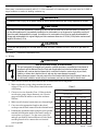
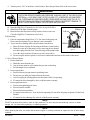
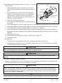
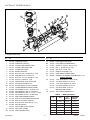
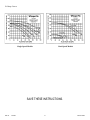
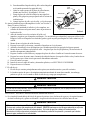
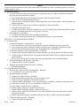
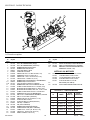
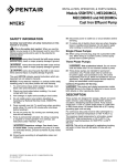
WhisperFlo® Pump Owner's Manual
IMPORTANT SAFETY INSTRUCTIONS
READ AND FOLLOW ALL INSTRUCTIONS
SAVE THESE INSTRUCTIONS
Table of Contents
SECTION I.
GENERAL INFORMATION .............................................................................................................. 2
SECTION II.
MAINTENANCE .............................................................................................................................. 3
SECTION III.
SERVICE ........................................................................................................................................ 5
SECTION IV.
RESTART INSTRUCTIONS ............................................................................................................. 6
SECTION V.
TROUBLESHOOTING ..................................................................................................................... 7
SECTION VI.
TECHNICAL DATA .......................................................................................................................... 8
A. REPLACEMENT PARTS ............................................................................................................................ 8
B. PUMP CURVES .......................................................................................................................................... 9
SECCIÓN I.
INFORMACIÓN GENERAL ........................................................................................................... 12
WARNING
Before installing this product, read and follow all warning notices and instructions accompanying this pump.
Failure to follow safety warnings and instructions can result in severe injury, death, or property damage. Call
(800) 831-7133 for additional free copies of these instructions.
Important Notice
Attention Installer.
This manual contains important information about the installation, operation and safe use of this
product. This information should be given to the owner/operator of this equipment.
WARNING
Risk of electrical shock or electrocution.
This pool pump must be installed by a licensed or certified electrician or a qualified pool
serviceman in accordance with the National Electrical Code and all applicable local codes and
ordinances. Improper installation will create an electrical hazard which could result in death or
serious injury to pool users, installers, or others due to electrical shock, and may also cause
damage to property.
Always disconnect power to the pool pump at the circuit breaker before servicing the pump.
Failure to do so could result in death or serious injury to serviceman, pool users or others due to
electric shock.
Pentair Pool Products
1620 Hawkins Ave., Sanford, NC 27330 • (919) 774-4151
10951 West Los Angeles Ave., Moorpark, CA 93021 • (805) 523-2400
Rev. E
1-25-02
Listed
227T
1
Listed
P/N 071109
NOTE
When pump is mounted permanently within 5 ft. of the inside walls of a swimming pool, you must use a No. 8 AWG or
larger conductor to connect to bonding conductor lug.
WARNING
To reduce the risk of injury, do not permit children to use this product unless they are closely supervised at all times.
CAUTION
This pump is for use with permanently installed pools and may also be used with hot tubs and spas if so marked. Do
not use with storable pools. A permanently installed pool is constructed in or on the ground or in a building such that it
cannot be readily disassembled for storage. A storable pool is constructed so that it may be readily disassembled for
storage and reassembled to its original integrity and has a maximum dimension of 18 feet (5.49m) and a maximum wall
height of 42 inches (1.07m).
CAUTION
For hot tubs and spa pumps, do not install within an outer enclosure or beneath the skirt of a hot tub or spa unless so
marked.
SECTION I.
GENERAL INFORMATION
A. Wiring.
WARNING
Risk of electrical shock or electrocution.
This pool pump must be installed by a licensed or certified electrician or a qualified pool serviceman in
accordance with the National Electrical Code and all applicable local codes and ordinances. Improper
installation will create an electrical hazard which could result in death or serious injury to pool users,
installers, or others due to electrical shock, and may also cause damage to property.
Always disconnect power to the pool pump at the circuit breaker before servicing the pump. Failure to do
so could result in death or serious injury to serviceman, pool users or others due to electric shock.
1. Make sure all electrical breakers and switches are turned off before wiring motor.
2. Make sure that the wiring voltage matches the motor
voltage (230v or 115v). If they do not match the motor
Chart 1.
will burn up.
SUPPLY WIRE SIZES (AWG)
3. Choose a wire size from the Chart 1. When in doubt
(size and length by horsepower)
use a heavier gauge (larger diameter) wire. Heavier
gauge will allow the motor to run cooler and more
hp
115 volts
230 volts
efficient.
50 ft. 100 ft. 150 ft. 50 ft. 100 ft.
4. Make sure all electrical connections are clean and tight.
1/3
14
14
12
14
14
5. Cut wires to the appropriate length so they don’t
1/2
14
12
10
14
14
overlap or touch when connected to the terminal board.
3/4
12
12
10
14
14
6. Permanently ground the motor using the green ground
1
12
10
8
14
14
terminal located on the inside of the motor canopy or
access plate, see Figure 1. Use the correct wire size
1½
10
10
8
14
14
and type specified by National Electrical Code. Make
2
10
8
8
14
12
sure the ground wire is connected to an electrical
3
12
12
service ground.
P/N 071109
2
Rev. E
150 ft.
14
14
14
14
12
12
10
1-25-02
7. Bond the motor to the pool structure in accordance with the
National Electrical Code. Use a solid No. 8 AWG or larger
copper conductor. Run a wire from the external bonding to the
pool bonding structure, see Figure 1.
8. Connect the pump permanently to a circuit. Make sure no other
lights or appliances are on the same circuit.
Bonding Lug
Ground Screw
NOTE
It is important that the O-ring be kept clean and well lubricated. We recommend a
silicone base lubricant for best results.
Figure 1.
B. The Pump Strainer Basket.
This unit, sometimes referred to as the ‘Hair and Lint Pot’, is the unit in front of the volute. Inside the chamber is the
basket which must be kept clean of leaves and debris at all times. View basket through the ‘See Through Lid’ to inspect
for leaves and debris.
Regardless of the length of time between filter cleaning, it is most important to visually inspect the hair and lint pot basket
at least once a week. A dirty basket will reduce the efficiency of the filter and heater and also put an abnormal stress on
the pump motor which would result in a costly repair bill.
SECTION II. MAINTENANCE
WARNING
DO NOT open the strainer pot if pump fails to prime or if pump has been operating without water in the strainer pot. Pumps
operated in these circumstances may experience a build up of vapor pressure and may contain scalding hot water. Opening
the pump may cause serious personal injury. In order to avoid the possibility of personal injury, make sure the suction and
discharge valves are open and strainer pot temperature is cool to touch, then open with extreme caution.
CAUTION
To prevent damage to the pump and filter and for proper operation of the system, clean pump strainer and skimmer
baskets regularly.
A. Pump Strainer Basket Cleaning Procedures.
1.
2.
3.
4.
5.
Turn off motor.
Relieve pressure in the system.
Turn the clamp and lid in a counter-clockwise direction until it stops.
Turn the clamp and lid set to remove the clamp and lid.
Put the debris from the basket into the trash and rinse out the basket.
If the basket is cracked, it should be replaced.
6. Replace the basket and fill the pump pot and volute up to the inlet
port with water.
7. Clean the cover, cover O-ring, and sealing surface of the pump pot.
Grease the O-ring with Teflon or silicone.
8. Reinstall the lid by placing the clamp and the lid on the pot;
see Figure 2.
a. Make sure the lid O-ring is properly placed. Seat the clamp and
lid then turn clockwise until the handles are horizontal;
see Figure 3.
Rev. E
1-25-02
3
Clamp, pot
Lid
O-ring, lid
Basket
Pot
Figure 2.
P/N 071109
9. Turn the power “ON” at the house circuit breaker. Reset the pool time clock to the correct time.
WARNING
THIS FILTER OPERATES UNDER HIGH PRESSURE. WHEN ANY PART OF THE CIRCULATING
SYSTEM (e.g., LOCK RING, PUMP, FILTER, VALVES, ETC.) IS SERVICED, AIR CAN ENTER
THE SYSTEM AND BECOME PRESSURIZED. PRESSURIZED AIR CAN CAUSE THE LID TO
BLOW OFF WHICH CAN RESULT IN SEVERE INJURY, DEATH, OR PROPERTY DAMAGE. TO
AVOID THIS POTENTIAL HAZARD, FOLLOW THESE INSTRUCTIONS.
10. Open the High Flow™ manual air relief valve on top of the filter.
Clamp
11. Stand clear of the filter. Start the pump.
Lid
12. Bleed air from the filter until a steady stream of water comes out.
Close the High Flow™ manual air relief valve.
B. Winterizing.
1. If the air temperature drops below 35° F. the water in the pump can
freeze and cause damage. Freeze damage is not warrantable.
Volute
2. To prevent freeze damage follow the procedures listed below.
a. Shut off electrical power for the pump at the house circuit breaker.
b. Drain the water out of the pump case by removing the two thumbFigure 3.
twist drain plugs from the case. Store the plugs in the pump basket.
c. Cover the motor to protect it from severe rain, snow and ice.
d. Do not wrap the motor in plastic. It will cause condensation and rust on the inside of the motor.
C. Care of Electric Motor.
1. Protect from heat.
a. Shade the motor from the sun.
b. Any enclosure must be well ventilated to prevent overheating.
c. Provide ample cross ventilation.
2. Protect against dirt.
a. Protect from any foreign matter or splashing water.
b. Do not store (or spill) pool chemicals near the motor.
c. Avoid sweeping or stirring up dust near the motor while it is operating.
d. If a motor has been damaged by dirt it voids the motor warranty.
3. Protect against moisture.
a. Protect from splashing pool water.
b. Protect from the weather.
c. Protect from lawn sprinklers.
d. If a motor has become wet - let it dry before operating. Do not allow the pump to operate if it has been
flooded.
e. If a motor has been damaged by water it voids the motor warranty.
NOTE
DO NOT wrap motor with plastic or other air tight materials. The motor may be covered during a storm, for winter
storage, etc., but never when operating, or expecting operation.
NOTE
When replacing the motor, be certain that the motor support is correctly positioned to support the size of motor being
installed.
P/N 071109
4
Rev. E
1-25-02
SECTION III. SERVICE
WARNING
Risk of electrical shock or electrocution.
This pool pump must be installed by a licensed or certified electrician or a qualified pool serviceman in
accordance with the National Electrical Code and all applicable local codes and ordinances. Improper
installation will create an electrical hazard which could result in death or serious injury to pool users,
installers, or others due to electrical shock, and may also cause damage to property.
Always disconnect power to the pool pump at the circuit breaker before servicing the pump. Failure to do
so could result in death or serious injury to serviceman, pool users or others due to electric shock.
Read all servicing instructions before working on the pump.
WARNING
DO NOT open the strainer pot if pump fails to prime or if pump has been operating without water in the strainer pot. Pumps
operated in these circumstances may experience a build up of vapor pressure and may contain scalding hot water. Opening
the pump may cause serious personal injury. In order to avoid the possibility of personal injury, make sure the suction and
discharge valves are open and strainer pot temperature is cool to touch, then open with extreme caution.
A. Pump Disassembly.
1. All moving parts are located in the rear sub-assembly of this pump.
Tools required:
a. 3/32 inch Allen head wrench.
b. ½ inch open end wrench.
c. 9/16 inch open end wrench.
d. Flat blade screwdriver.
2. To remove and repair the motor sub-assembly perform the following procedures.
a. Turn off the pump circuit breaker at the main panel.
b. Drain the pump by removing the drain plugs.
c. Remove the 6 bolts that hold the main pump body (strainer pot/volute) to the rear sub-assembly.
d. GENTLY pull the two pump halves apart, removing the rear sub-assembly.
e. Use a 3/32 inch Allen head wrench to loosen the two holding screws located on the diffuser.
CAUTION
Be sure not to scratch or mar the polished shaft seal faces; seal will leak if faces are damaged.
f. Hold the impeller securely in place and remove the impeller lock screw by using a flat blade
screwdriver. The screw is a left-handed thread and loosens in a clockwise direction.
g. Remove the shaft cap located at the back of the motor and hold the shaft secure with a ½ inch
(Century) or 7/16 inch (Franklin) open-end wrench. On A. 0. Smith motors, remove the motor canopy,
move the capacitor to one side and hold the shaft with a 7/16 inch open-end wrench.
h. To unscrew the impeller from the shaft, twist the impeller counterclock- wise.
i.
Remove the four bolts from the seal plate to the motor, using a 9/16 inch wrench.
j.
Place the seal plate face down on a flat surface and tap out the carbon/spring seat.
k. Clean the seal plate, seal housing, and the motor shaft.
Rev. E
1-25-02
5
P/N 071109
B. Pump Reassembly/Seal Replacement; see Section V, Technical
Data, Figure 4.
Bolt
1. When installing the replacement shaft seal, use silicone
Seal Plate
sealant on the metal portion, before pressing into the seal
plate.
Gasket
2. Before installing the ceramic section of the seal into the
impeller, be sure the impeller is clean. Use a light density
Lockscrew
Water Slinger
soap and water to seal the seal. Press the seal into the
Motor
Shaft
impeller with your thumbs and wipe off the ceramic and
carbon faces with a clean cloth.
Impeller
Lockscrew Seal
3. Remount the seal plate to the motor.
4. Grease the motor shaft thread and screw impeller onto the
Figure 4.
motor shaft.
5. Screw in the impeller lock screw (counter-clockwise to tighten).
6. Remount the diffuser onto the seal plate. Make sure the plastic pins and holding screw inserts are aligned.
7. Grease the diffuser O-ring and seal plate gasket or O-ring prior to reassembly.
8. Grease the bolt threads, assemble the motor sub-assembly to the strainer pot-pump body by using the two
through bolts for proper alignment. Do not tighten the through bolts until all 6 bolts are in place and finger
tightened.
9. Fill the pump with water.
10. Reinstall the pump lid and plastic clamp; see SECTION II. START-UP.
11. Reprime the system.
C. The Shaft Seal.
1. The Shaft Seal consists primarily of two parts, a rotating member and a ceramic seal.
2. The pump requires little or no service other than reasonable care, however, a Shaft Seal may occasionally
become damaged and must be replaced.
CAUTION
The polished and lapped faces of the seal could be damaged if not handled with care.
CAUTION
In mild climate area, when temporary freezing conditions may occur, run your filtering equipment all night to prevent
freezing.
SECTION IV. RESTART INSTRUCTIONS
A. If pump is installed below the water level of the pool, close return and suction lines prior to opening hair and
lint pot on pump. Make sure to re-open valves prior to operating.
CAUTION
DO NOT run the pump dry. If the pump is run dry, the mechanical seal will be damaged and the pump will start leaking. If this
occurs, the damaged seal must be replaced. ALWAYS maintain proper water level in your pool (half way up skimmer opening). If
the water level falls below the skimmer opening, the pump will draw air through the skimmer, losing the prime and causing the
pump to run dry, resulting in a damaged seal.
NOTE
Continued operation in this manner could cause a loss of pressure, resulting in damage to the pump case, impeller and seal.
P/N 071109
6
Rev. E
1-25-02
B. Priming the Pump.
1. The pump strainer pot must be filled with water before the pump is initially started. Follow these steps to
prime the pump.
a.
b.
c.
d.
e.
f.
Remove the pump lid plastic clamp. Remove the pump lid.
Fill the pump strainer pot with water.
Reassemble the pump cover and plastic clamp onto the strainer pot. The pump is now ready to prime.
Open the air release valve on the filter, and stand clear of the filter.
Turn on the switch or time clock.
When water comes out of the air release valve, close the valve. The system should now be free of air
and recirculating water to and from the pool.
2. For 2-speed pumps:
a. Pump should run on high-speed for priming.
b. The pump should not run longer than 8 minutes before priming is achieved.
SECTION V. TROUBLESHOOTING
A. Failure to Pump.
1. Pump will not prime - too much air. - Remedy:
a. Check suction piping and valve glands on any suction gate valves.
b. Secure lid on pump strainer pot and make sure lid gasket is in place.
c. Check water level to make sure skimmer is not drawing air.
2. Pump will not prime--not enough water. - Remedy:
a. Make sure suction lines, pump strainer, and pump volute are full of water.
b. Make sure valve on suction line is working and open, (some systems do not have valves).
c. Check water level to make sure water is available through skimmer.
3. Pump strainer clogged. - Remedy:
a. Clean pump strainer pot.
4. Pump strainer gasket defective. - Remedy:
a. Replace gasket.
B. Reduced Capacity and/or Head.
1. Air pockets or leaks in suction line. - Remedy:
a. See item A.1. of this section, above.
2. Clogged impeller. Remedy:
a. Turn off electrical power to the pump.
b. Remove the clamp that holds the volute to the seal plate.
c. Slide the motor and seal plate away from the volute.
d. Clean debris from impeller. If debris cannot be removed, complete the following steps.
(1)
(2)
(3)
Remove left hand thread anti-spin bolt and O-ring.
Remove, clean and reinstall impeller.
Reinstall anti-spin bolt and O-ring.
e. Reinstall wear-ring, diffuser, and O-ring.
f. Reinstall motor and seal plate into volute aligning with keyway at top of volute.
g. Reinstall clamp around seal plate and volute and tighten securely.
3. Pump strainer clogged. - Remedy:
a. Clean suction trap.
Rev. E
1-25-02
7
P/N 071109
SECTION VI. TECHNICAL DATA
26
28
27
A. Replacement Parts.
Item
No.
Part
No.
1
1
2
2
3
4
5
6
7
8
9
10
10a
11
12
13
13
14
15
16
16a
17
18
357150
357199
070795
357151
350013
070387
070430
072184
070431
071403
357102
350015
357157
071444
071660
072928
072927
071652
075713
071734
071728
070429
074564
357173
070927
357159
19
19a
P/N 071109
Item
No.
Description
CLAMP POT (Black)
CLAMP POT (Almond)
COVER CLEAR AQ/WFE PUMP
COVER CLEAR WFE PUMP
O-RING WFE COVER
BASKET AQ & WFE
BOLT 3/8 16 X 1.15 HEX HD s/s, 4 req.
WASHER 3/8 s/s X 13/16 O.D. 6
BOLT 3/8 - 16 X 1/75 HX HD s/s, 2 req.
NUT 3/8 - 16 HEX. hd., 2 req.
GASKET SEAL PLATE WFE PUMP
VOLUTE WFE PUMP & POT
VOLUTE (CSA/CUL ONLY) CANADA
O-RING PARKER #2-238 WFE PUMP
SET SCREW #4-40 X 1-1/8 WFE, 2 req.
DIFFUSER assy. WFE-12, 3 HP ONLY
DIFFUSER assy. WFE-2 - 8, .5 HP – 2.5 HP
SET SCREW .25 20 X 1 LH PHILLIPS
WFE PUMP RUBBER WASHER
SEAL PA-7 W/CERAMIC SEAT, PS1000
SEAL A7 s/s PS201 (CSA/CUL)
BOLT 3/8-16 X 7/8 s/s HEX hd., 4 req.
SEAL PLATE WFE
SEAL PLATE / CUP (CSA/CUL)
FOOT WFE - 4 PUMP
FOOT (CANADA ONLY)
Part
No.
Description
20
20a
21
22
23
24
24a
25
070929
357160
071657
071406
072183
071131
357161
074629
26
071313
071314
071315
071316
071317
27
28
357149
FOOT INSERT WFE PUMP
FOOT INSERT (CANADA ONLY)
SCREW ¼ - 20 X 1 in. HH s/s, 2 req.
NUT ¼ - 20 HEX. hd. s/s, 2 req.
Wsh. FLAT ¼ X 5/8 , 2 req.
KNOB PLUG DRAIN, 2 req.
KNOB, DRAIN (CANADA ONLY)
GASKET, FLAT WASHER WFE PMP. DRN., 2 req.
ITEM 26, MOTORS
.75 HP 60HZ /WFE-2, 3 & 24, 29 Lbs.
1 HP 60HZ /WFE-4 & 26, 33 Lbs.
1.5 HP 60HZ /WFE-6 & 28, 39 Lbs.
2 HP 60HZ /WFE-8 & 30, 40 Lbs.
3 HP 60 HZ /WFE-12, 40 Lbs.
IMPELLER (SEE CHART)
VOLUTE REPLACEMENT KIT
ITEM 27 — IMPELLER CHART
8
HP
SIZE
STD
PART NO.
CANADIAN
CSA/CUL
½
WF, WFE-2, -23
073126
357167
¾
WF, WFE-3, -24
073127
357168
1
WF, WFE-4, -26
073128
357169
1½
WF, WFE-6, -28
073129
357170
2
WF, WFE-8, -30
073130
357171
3
WFE-12
073131
357172
Rev. E
1-25-02
B. Pump Curves
Dual Speed Models
Single Speed Models
SAVE THESE INSTRUCTIONS.
Rev. E
1-25-02
9
P/N 071109
Pentair Pool Products WhisperFlo®
Circulating Pump Limited Warranty
Pentair Pool Products manufactures its WhisperFlo® circulating
pumps under high standards of workmanship and with high
quality materials. Accordingly, Pentair Pool Products expressly
warrants those pump models as follows:
WARRANTY COVERAGE - All pump component parts
actually manufactured by Pentair Pool Products, and the
pump’s respective motor is warranted to be free from defects in
material and/or workmanship for a period of three (3) years from
date of purchase. The obligation of Pentair Pool Products
under this warranty will be limited to either repair or
replacement of the product, at Pentair Pool Products option.
EXCLUSIONS FROM THIS WARRANTY - This warranty does
not cover:
1. Any item manufactured by other companies and installed
by Pentair Pool Products. Such items may carry warranties
offered by the original manufacturer.
2. Problems resulting from oversizing of pump and/or
reduction of valve piping size, or from failure to turn pump
off before changing the position of the filter valve or any
operating valves for the pool and its accessories.
3. Problems resulting from failure to comply with instructions
contained in the Owner's Manual.
4. Problems resulting from abuse, misuse, negligence or
accident by any party other than Pentair Pool Products,
such as but not limited to, damage to parts caused by
installers, damage to pump parts caused by ‘dry’ operation
(loss of prime or obstruction in plumbing lines).
Pentair Pool Products is not, however responsible under
this warranty for any cost of shipping or transportation of
the filter or part thereof to or from the service department.
Also, Pentair Pool Products is not liable for any loss of time,
inconvenience, incidental expenses such as telephone calls,
labor or material charges incurred in connection with the
removal or replacement of the equipment, or any other
incidental or consequential damages. PLEASE NOTE: Some
states do not allow the exclusion or limitation or incidental
or consequential damages, so the above limitation or
exclusion may not apply to you.
PROCEDURE FOR OBTAINING PERFORMANCE: In order
to obtain the benefits of this warranty the consumer who
made the original retail purchase will contact Pentair Pool
Products Customer Service Department, 10951 W. Los
Angeles Ave., Moorpark, CA 93021 as soon as possible
after discovery of the defect, but in no event later than the
expiration date of the warranty period provided in this
warranty. Upon receipt of this communication, Pentair Pool
Products will promptly notify the customer of the address to
which the defective item may be shipped. The customer
shall then ship the item, freight prepaid, to the address
indicated together with a letter stating the model number,
serial number, and the date of purchase of the item which is
claimed to be defective, and the name and address of the
consumer and a brief description of the problems
encountered.
WARRANTY PROTECTS ORIGINAL PURCHASER: This
warranty extends to the consumer who made the original
retail purchase only and is not enforceable by any other
party.
5. Problems resulting in whole or in part from alteration or
modification of the filter by any party.
6. Failures due to chemical corrosion caused by failure to
maintain the water chemistry in conformity with the
standard of the swimming pool and spa industry.
WARRANTY OBLIGATIONS OF PENTAIR POOL
PRODUCTS - Should a defect in workmanship and/or material
in any item covered by this warranty become evident during
the term of the warranty, then upon the consumer following the
procedures set forth below, Pentair Pool Products will, at its
option, repair or replace such item or part at its own cost and
expense.
WARRANTIES OR REPRESENTATIONS BY OTHERS: No
dealer or other person has any authority to make any
warranties or representations concerning Pentair Pool
Products or its products. Accordingly, Pentair Pool
Products is not responsible for any such warranties or
representations.
OTHER RIGHTS: This warranty gives you specific legal
rights and you may also have other rights which vary from
state to state.
Pentair Pool Products
1620 Hawkins Ave., Sanford, NC 27330 • (919) 774-4151
10951 West Los Angeles Ave., Moorpark, CA 93021 • (805) 523-2400
P/N 071109
10
Rev. E
1-25-02
Manual de referencia de la bomba WhisperFlo®
INSTRUCCIONES DE SEGURIDAD IMPORTANTES
LEA Y SIGA TODAS LAS INSTRUCCIONES
GUARDE ESTAS INSTRUCCIONES
Índice de materias
SECCIÓN I.
INFORMACIÓN GENERAL ..................................................................................................... 12
SECCIÓN II.
MANTENIMIENTO ................................................................................................................... 13
SECCIÓN III.
SERVICIO ............................................................................................................................... 15
SECCIÓN IV.
INSTRUCCIONES PARA ENCENDER DE NUEVO .................................................................. 16
SECCIÓN V.
LOCALIZADOR DE AVERÍAS ................................................................................................. 17
SECCIÓN VI.
DATOS TÉCNICOS .................................................................................................................. 18
A.
PIEZAS DE REEMPLAZO ...................................................................................................... 18
B.
CURVAS DE BOMBA .............................................................................................................. 19
AVISO
Antes de instalar este producto, lea y siga todos los avisos e instrucciones que vienen con esta bomba. Fallar en
seguir los avisos de seguridad e instrucciones puede resultar en lesión severa, muerte o daño a propiedad. Llame al
(800) 831-7133 para conseguir más copias gratis de estas instrucciones.
Aviso importante
Atención al instalador.
Este manual contiene información importante acerca de la instalación, la operación y uso seguro
de este producto. Se debe entregar esta información al dueño/usuario de este equipo.
AVISO
Riesgo de choque eléctrico o electrocución.
Se debe instalar esta bomba de piscina por un electricista certificado o con licencia o por un
trabajador de servicios de piscinas calificado según el Código Eléctrico Nacional y todos
códigos locales y decretos aplicables. Instalación inadecuada creará un peligro eléctrico que
puede resultar en muerte o lesión grave a los usuarios de la piscina, instaladores u otras
personas debido a choque eléctrico, y también puede causar daño a propiedad.
Siempre desconecte el corriente a la bomba de piscina en el cortacircuito antes de dar
mantenimiento a la bomba. Fallar en esto puede resultar en muerte o lesión grave a la
persona que hace el mantenimiento, usuarios de la piscina u otras personas debido a choque
eléctrico.
Pentair Pool Products
1620 Hawkins Ave., Sanford, NC 27330 • (919) 774-4151
10951 West Los Angeles Ave., Moorpark, CA 93021 • (805) 523-2400
Rev. E
1-25-02
Listed
227T
11
Listed
P/N 071109
NOTA
Cuando la bomba se monta permanentemente dentro de 5 pies (1.524 m) de las paredes interiores de una piscina, tiene que usar
un No. 8 AWG o conductor más grande para conectar al tirón de conductor que pega.
AVISO
Para reducir el riesgo de lesión, no permite que los niños usen este producto a menos que alguien esté supervisando
cuidadosamente en todo momento.
ADVERTENCIA
Esta bomba es para usar con piscinas instaladas de manera permanente y también se puede usar con bañeras con
agua caliente (hot tubs) y balnearios, si está marcada así. No la use con piscinas que se pueden almacenar. Una
piscina instalada de manera permanente es construida o encima del suelo o en un edificio de tal manera que no se
puede desarmar fácilmente para almacenarla. Una piscina que se puede almacenar es construida de manera que se
puede desarmar fácilmente para almacenarla y armar de nuevo a su integridad original y tiene una dimensión máxima
de 18 pies (5.49m) y una altura de pared máxima de 42 pulgadas (1.07m).
ADVERTENCIA
Para bombas de bañeras con agua caliente (hot tubs) y balnearios, no haga la instalación dentro de un cercado o
debajo de la falda de una bañera con agua caliente (hot tub) o balneario a menos que esté marcada así.
SECCIÓN I. INFORMACIÓN GENERAL
A. Alambrado.
ADVERTENCIA
Riesgo de choque eléctrico o electrocución.
Esta bomba de piscina tiene que instalarse por un electricista certificado o con licencia o un trabajador
calificado de servicio para piscinas según el Código Eléctrico Nacional y todos códigos y decretos
locales y aplicables. Instalación inadecuada creará un peligro eléctrico que podría resultar en muerte o
lesión grave a los usuarios de la piscina, instaladores u otras personas debido a choque eléctrico, y
también podría causar daño a propiedad.
Siempre desconecte el corriente a la bomba de piscina en el cortacircuito antes de proveer
mantenimiento para la bomba. Fallar en hacer esto podría resultar en muerte o lesión grave a la persona
haciendo el mantenimiento, usuarios de la piscina u otras personas debido a choque eléctrico.
1. Asegúrese que todos cortacircuitos e interruptores están apagados antes de instalar el alambrado en el motor.
2. Asegúrese que el voltaje de alambrado corresponde con el voltaje del motor (230v o 115v). Si los voltajes no
corresponden, se quemará el motor.
Tabla 1.
3. Escoja un tamaño de alambre de la Tabla 1. Cuando esté en
duda, use un alambre con calibre más pesado (diámetro más
TAMAÑOS DE ALAMBRES DE SUMINISTRO (AWG)
grande). Calibre más pesado permitirá que el motor funcione
(tamaño y longitud según caballo de vapor)
con menos calor y que dé un buen rendimiento.
115 voltios
230 voltios
hp
4. Asegúrese que todas conecciones eléctricas están limpias y
(caballos) 50 ft. 100 ft. 150 ft. 50 ft. 100 ft. 150 ft.
apretadas.
1/3
14
14
12
14
14
14
5. Corte los alambres para que tengan la longitud adecuada para que
1/2
14
12
10
14
14
14
no se traslapen ni se toquen cuando están conectadas a la placa
3/4
12
12
10
14
14
14
de terminales.
1
12
10
8
14
14
14
6. Conecte el motor con tierra de manera permanente usando el
1½
10
10
8
14
14
12
terminal verde de tierra ubicado en el interior del canapé de motor
2
10
8
8
14
12
12
o placa de acceso, vea Gráfica 1. Use el tamaño y tipo correcto
3
12
12
10
de alambre especificado por el Código Eléctrico Nacional.
Asegúrese que el alambre de tierra está conectado a una tierra de servicio eléctrico.
P/N 071109
12
Rev. E
1-25-02
7. Una el motor a la estructura de piscina según el Código
Eléctrico Nacional. Use un No. 8 AWG sólido o conductor
de cobre más grande. Corra un alambre de la unión externa
a la estructura de unión de piscina, vea Gráfica 1.
8. Conecte la bomba a un circuito de manera permanente.
Asegúrese ningunos otros aparatos o luces están conectados
en el mismo circuito.
Gráfica 1.
Bondingde
Lug
Tornillo
unión
Ground Screw
Tornillo
de tierra
NOTA
Es importante que el anillo en O se mantenga limpio y con bueno
engrase. Recomendamos un lubricante basado en silicona para los
mejores resultados.
B. La canasta que cola para la bomba.
Esta unidad, que a veces se llama la ‘Olla de pelo y pelusa’, es la unidad delante de la voluta. Adentro del
recipiente está la canasta la cual siempre tiene que mantenerse limpia de hojas y de escombros. Mire la
canasta a través de la ‘Tapa Transparente’ para ver si hay hojas y escombros.
Sin reparar en la cantidad de tiempo entre limpieza de filtro, es de mayor importancia inspeccionar
visualmente la canasta de olla de pelo y pelusa por lo menos una vez por semana. Una canasta sucia reducirá
el rendimiento del filtro y del calentador y también causará una tensión anormal en el motor de bomba lo cual
resultaría en un gasto caro de reparación.
SECCIÓN II. MANTENIMIENTO
ADVERTENCIA
NO abra el tambor del filtro colador si la bomba falla en llenarlo o si ha estado operando sin agua en el mismo. Las
bombas que operen bajo estas circunstancias podrían experimentar una acumulación de vapor y contener agua
hirviendo. La apertura de la bomba podría dar lugar a serias lesiones personales.
Para evitar la posibilidad de lesiones personales, asegúrese que las válvulas de succión y descarga estén abiertas y
que el tambor del filtro colador esté frío, y luego ábralo con sumo cuidado.
ADVERTENCIA
Clamp,
pot olla
Abrazadera,
Para prevenir daño a la bomba y al filtro y para funcionamiento adecuado del
sistema, limpie regularmente el colador de bomba y las canastas que desnatan.
Tapa
Lid
A. Procedimientos para la limpieza de canasta de colador de bomba.
1. Apague el motor.
2. Saque la presión en el sistema.
Anillo enlidO, tapa
O-ring,
3. Gire la abrazadera y tapa en el sentido opuesto de las agujas del reloj
hasta que para.
Canasta
4. Gire el juego de abrazadera y tapa para quitar la abrazadera y tapa.
Basket
5. Tire los escombros de la canasta en la basura y enjuague la canasta.
Olla
Pot
Si la canasta está rajada, debe reemplazarse.
6. Hay que reemplazar la canasta y llenar la olla de bomba y la voluta
hasta el puerto de entrada con agua.
7. Limpie la tapa, cubra el anillo en O y sellar la superficie de la olla de
bomba. Aplique grasa al anillo en O con teflón® o silicona.
8. Instale de nuevo la tapa al poner la abrazadera y la tapa en la olla;
vea Gráfica 2.
Gráfica 2.
a. Asegúrese que la tapa y anillo en O están puesto adecuadamente.
Monte la abrazadera y la tapa, entonces gire en el sentido de las agujas del reloj hasta que las manillas están
horizontales; vea Gráfica 3.
Rev. E
1-25-02
13
P/N 071109
9. Encienda el corriente en posición de “ON” en el cortacircuito de la casa. Reajuste la hora en el reloj de
piscina para que mostre la hora correcta.
AVISO
ESTE FILTRO FUNCIONA BAJO ALTA PRESIÓN. CUANDO CUALQUIER PIEZA DEL SISTEMA DE
CIRCULACIÓN (p.ej., ANILLO DE BLOQUEADOR, BOMBA, FILTRO, VÁLVULAS, ETC.) RECIBE
MANTENIMIENTO, AIRE PUEDE ENTRAR EN EL SISTEMA Y HACERSE PRESURIZADO. AIRE
PRESURIZADO PUEDE CAUSAR QUE LA TAPA SE REVIENTE LO CUAL PUEDE RESULTAR EN
LESIÓN SEVERA, MUERTE, O DAÑO A PROPIEDAD. PARA EVITAR ESTE PELIGRE POTENCIAL,
SIGA ESTAS INSTRUCCIONES.
10. Abra la válvula manual de escape de aire High Flow ™ en la parte superior del filtro.
11. Manténgase a distancia del filtro. Encienda la bomba.
12. Sangre aire del filtro hasta que sale un corriente constante de agua.
B. Adaptar para el invierno.
1. Si la temperatura de aire baja a menos de 35° F (1.667 C), el agua en la bomba puede congelarse y causar
daño. Daño de congelación no está bajo garantía.
2. Para prevenir daño de congelación siga los procedimientos mencionados abajo.
a. Apague el corriente eléctrico para la bomba en el cortacircuito de la casa.
b. Vacíe el agua de la caja de bomba al quitar los dos tapones de drenaje que se dan vuelta usando el dedo
gordo de la caja. Guarde los tapones en la canasta de bomba.
c. Cubra el motor para protegerlo de lluvia, nieve y hielo severo.
d. No cubra el motor en plástico. Causará vaho y oxidación en el interior del motor.
C. Mantenimiento del motor eléctrico.
1. Protección contra el calor.
a. Déle sombra al motor del sol.
b. Cualquier cercado tiene que tener buena ventilación para prevenir recalentarse.
c. Provea ventilación amplia que pase por ahí.
Abrazadera
Clamp
2. Protección contra la tierra.
Tapa
Lid
a. Proteja contra cualquier sustancia ajena o agua que salpica.
b. No guarde (ni derrame) química de la piscina cerca del motor.
c. Evite barrer o agitar polvo cerca del motor mientras que esté
funcionando.
d. Si un motor se ha dañado con tierra hace nula la garantía de
motor.
Volute
Voluta
3. Protección contra la humedad.
a. Proteja contra agua que salpica de la piscina.
b. Proteja contra el clima.
Gráfica 3.
c. Proteja contra rociadera de césped.
d. Si el motor se ha mojado – permite que se seque antes de usarlo. No permite que se use la bomba si se ha
inundado.
e. Si un motor se ha dañado por agua hace nula la garantía de motor.
NOTA
NO cubra el motor con plástico ni con otros materiales herméticos. Se puede cubrir el motor durante una tormenta, para almacenar
durante el invierno, etc., pero nunca cuando se está usando o cuando se espera usar.
NOTA
Cuando está reemplazando el motor, asegúrese que el soporte de motor está colocado correctamente para soportar el tamaño del
motor que se está instalando.
P/N 071109
14
Rev. E
1-25-02
SECCIÓN III. SERVICIO
AVISO
Riesgo de choque eléctrico o electrocución.
Esta bomba de piscina tiene que instalarse por un electricista certificado o con licencia o un trabajador
calificado de servicio para piscinas según el Código Eléctrico Nacional y todos códigos y decretos
locales y aplicables. Instalación inadecuada creará un peligro eléctrico que podría resultar en muerte o
lesión grave a los usuarios de la piscina, instaladores u otras personas debido a choque eléctrico, y
también podría causar daño a propiedad.
Siempre desconecte el corriente a la bomba de piscina en el cortacircuito antes de proveer
mantenimiento para la bomba. Fallar en hacer esto podría resultar en muerte o lesión grave a la persona
haciendo el mantenimiento, usuarios de la piscina u otras personas debido a choque eléctrico.
Lea todas las instrucciones de mantenimiento antes de trabajar en la bomba.
ADVERTENCIA
NO abra el tambor del filtro colador si la bomba falla en llenarlo o si ha estado operando sin agua en el mismo. Las
bombas que operen bajo estas circunstancias podrían experimentar una acumulación de vapor y contener agua
hirviendo. La apertura de la bomba podría dar lugar a serias lesiones personales.
Para evitar la posibilidad de lesiones personales, asegúrese que las válvulas de succión y descarga estén abiertas y
que el tambor del filtro colador esté frío, y luego ábralo con sumo cuidado.
A. Desmontaje de bomba.
1. Todas piezas móviles se encuentran en el montaje de abajo por atrás de esta bomba.
Herramientas requeridas:
a. Llave de boca de 3/32 pulgada (.2381 cm).
b. Llave de boca de ½ pulgada (15.24 cm).
c. Llave de boca de 9/16 pulgada (1.429 cm).
d. Destornillador con cabeza plana.
2. Para quitar y reparar el montaje de abajo del motor ejecute los siguientes procedimientos.
a. Apague el cortacircuito de bomba en el panel principal.
b. Vacíe la bomba al quitar los tapones de drenaje.
c. Quite los 6 pernos que sujetan el cuerpo de bomba principal (olla de colador/voluta) al montaje de
abajo por atrás.
d. SUAVEMENTE separe las dos mitades de bomba, quitando el montaje de abajo por atrás.
e. Use una llave de boca de 3/32 pulgada (.2381 cm) para desapretar los dos tornillos que soportan y que
se encuentran en el difusor.
ADVERTENCIA
Asegúrese de no rayar ni dañar las caras pulidas que sellan el eje; el sello tendrá una chorreo si se dañan las caras.
f. Mantenga el impulsor seguramente en lugar y quite el tornillo de llave del impulsor al usar un
destornillador con cabeza plana. Este tornillo tiene rosca a mano izquierda y se desaprieta en el sentido
de las agujas del reloj.
g. Quite la tapa del eje que se encuentra en la parte de atrás del motor y mantenga el eje seguro con una
llave de boca de ½ pulgada (15.24 cm) (Century) o de 7/16 pulgada (1.111 cm) (Franklin). En
motores A.0. Smith, quite el canapé de motor, mueva el condensador a un lado y mantenga el eje con
una llave de boca de 7/16 pulgada (1.111 cm).
Rev. E
1-25-02
15
P/N 071109
h. Para destornillar el impulsor del eje, déle vuelta al impulsor
Bolt
Perno
en el sentido opuesto de las agujas del reloj.
i. Quite los cuatro pernos de la placa de sello al motor,
usando una llave de 9/16 pulgada (1.429 cm).
Sealde
Plate
Placa
sello
j. Ponga la placa de sello boca abajo en una superficie
plana y déle golpecito para que pueda salir el asiento de
Impaque
Gasket
carbón/resorte.
Tornillo
k. Limpie la placa de sello, caja de sello, y el eje de motor.
Lockscrew
de bloqueador
Water
DeflectorSlinger
de agua
B. Armar la bomba de nuevo/Reemplazar el sello; vea Sección V,
Eje de motor
Motor
Shaft
Datos Técnicos, Gráfica 4.
Impulsor
Impeller
1. Cuando está instalando el sello de eje de reemplazo, use
Sello de tornilloSeal
de bloqueador
Lockscrew
sellador de silicona en la parte metal, antes de presionar en
Gráfica 4.
la placa de sello.
2. Antes de instalar la sección cerámica del sello en el
impulsor, asegúrese que el impulsor está limpio. Use un jabón de poca densidad y agua para sellar el sello.
Empuje el sello en el impulsor con los dedos gordos y pase un paño para limpiar las caras cerámicas y de
carbón.
3. Monte de nuevo la placa de sello al motor.
4. Engrase la rosca del eje de motor y atornille el impulsor en el eje de motor.
5. Atornille el tornillo de cierre del impulsor (en el sentido opuesto de las agujas del reloj para apretar).
6. Monte de nuevo el difusor en la placa de sello. Asegúrese que las clavijas plásticas y las inserciones de
tornillos de mantener están alineado.
7. Engrase el anillo en O del difusor y empaque de placa de sello o el anillo en O antes de armar de nuevo.
8. Engrase las roscas de perno, arme el montaje de abajo del motor al cuerpo de olla de colar y bomba al usar
los dos pernos que corren a través para tener alineamiento adecuado.
9. Llene la bomba con agua.
10. Instale de nuevo la tapa de bomba y abrazadera plástica; vea SECCIÓN II. ENCENDER.
11. Prepare de nuevo el sistema.
C. El sello de eje.
1. El sello de eje consiste principalmente en dos piezas, un miembro rotativo y un sello cerámico.
2. La bomba requiere de poco o de ningún mantenimiento además de atención razonable, sin embargo,
podría ser que de vez en cuando se dañe el sello de eje y tenga que reemplazarse.
ADVERTENCIA
Las caras pulidas y labradas del sello se pueden dañar si no se usa con cuidado.
ADVERTENCIA
En una área de clima moderado, cuando puedan ocurrir condiciones de congelación, use su equipo de filtración durante
toda la noche para evitar congelación.
SECCIÓN IV. INSTRUCCIONES PARA ENCENDER DE NUEVO.
A. Si se instala la bomba debajo del nivel de agua en la piscina, cierre las líneas de regreso y de aspiración antes
de abrir la olla de pelo y pelusa en la bomba. Asegúrese de abrir de nuevo las válvulas antes de usar.
ADVERTENCIA
NO opere la bomba sin agua. Si la bomba opera sin agua, el sello mecánico se dañara y la bomba empezará fugar.
Si ocurre esto, se tiene que reemplazar el sello dañado. SIEMPRE mantenga un nivel de agua adecuado en su piscina
(la mitad de la longitud a la abertura de la desnatadora). Si el nivel de agua cae a debajo de la abertura de la
desnatadora, la bomba chupará aire a través de la desnatadora, perdiendo la imprimación y causando que la bomba
opere sin agua, resultando en un sello dañado.
P/N 071109
16
Rev. E
1-25-02
NOTA
Continuar con funcionamiento de este modo puede causar una pérdida de presión, resultando en daño a la caja de
bomba, impulsor y sello.
B. Imprimar la bomba.
1. La olla de colador de bomba tiene que llenarse con agua antes de que se empiece la bomba incialmente.
Siga estos pasos para imprimar la bomba.
a. Quite la abrazadera plástica de la tapa de la bomba. Quite la tapa de la bomba.
b. Llene la olla de colador de bomba con agua.
c. Arme de nuevo el cubierto de bomba y abrazadera plástica en la olla de colador. Ahora la bomba está
lista para imprimar.
d. Abra válvula de escape de aire en el filtro y manténgase a distancia del filtro.
e. Encienda el interruptor o reloj.
f. Cuando agua sale de la válvula de escape de aire, cierre la válvula. Este sistema ahora debe estar libre
de aire y circulando agua de nuevo a la piscina y de vuelta.
2. Para bomba de 2 velocidades:
a. La bomba debe funcionar en alta velocidad para imprimar.
b. La bomba no debe funcionar por más de 8 minutos antes de que se logre imprimar.
SECCIÓN V. LOCALIZADOR DE AVERÍAS.
A. Si la bomba falla.
1. La bomba no imprima – demasiado aire. – Remedio:
a. Revise la tubería de succión y las prensastopas en cualquier válvulas de puerta de aspiración.
b. Cierre la tapa en la olla de coladora de bomba y asegúrese que el empaque de tapa está en lugar.
c. Revise el nivel de agua para asegurarse que la desnatadora no está jalando aire.
2. La bomba no imprima—no hay agua suficiente. – Remedio:
a. Asegúrese que las líneas de aspiración, el colador de bomba, y la voluta de bomba están llenas con agua.
b. Asegúrese que la válvula en la línea de aspiración está funcionando y abierta, (algunos sistemas no
tienen válvulas).
c. Revise el nivel de agua para asegurarse que hay agua disponible a través de la desnatadora.
3. El colador de bomba está atascado. – Remedio:
a. Limpie la olla de coladora de bomba.
4. Empaque de colador de bomba defectuoso.- Remedio:
a. Reemplazar empaque.
B. Capacidad reducida y/o Espuma.
1. Bolsas de aire o fugas en la línea de aspiración. – Remedio:
a. Vea artículo A.1. de esta sección, arriba.
2. Impulsor atascado. Remedio:
a. Apague el corriente eléctrico a la bomba.
b. Quite la abrazadera que mantiene la voluta a la placa de sello.
c. Deslice el motor y la placa de sello fuera de la voluta.
d. Limpie escombros del impulsor. Si no se puede quitar los escombros, complete los siguientes pasos.
(1) Quite el perno contra-giro con rosca izquierda y el anillo en O.
(2) Quite, limpie e instale de nuevo el impulsor.
(3) Instale el perno contra-giro y el anillo en O de nuevo.
e. Instale el anillo de desgaste, difusor y anillo en O de nuevo.
f. Instale el motor y placa de sello de nuevo en la voluta, alineando con la ranura de pitón en la parte
superior de la voluta.
g. Instale la abrazadera de nuevo alrededor de la placa de sello y la voluta y apriente seguramente.
3. Colador de bomba atascado. – Remedio:
a. Limpie el depósito de aspiración.
Rev. E
1-25-02
17
P/N 071109
SECCIÓN VI. DATOS TÉCNICOS.
26
28
27
A. Piezas de reemplazo.
Núm.
Núm.
de
de pieza
artículo
1
1
2
2
3
4
5
6
7
8
9
10
10a
11
12
13
13
14
15
16
16a
17
18
18
19
19a
20
20a
21
22
23
357150
357199
070795
357151
350013
070387
070430
072184
070431
071403
357102
350015
357157
071444
071660
072928
072927
071652
075713
071734
071728
070429
074564
357173
070927
357159
070929
357160
071657
071406
072183
P/N 071109
Descripción
Núm.
Núm.
de
de pieza
artículo
OLLA DE ABRAZADERA (Negro)
OLLA DE ABRAZADERA (Almendra)
BOMBA AQ/WFE TAPA CLARA
BOMBA WFE TAPA CLARA
TAPA WFE ANILLO EN O
CANASTA AQ & WFE
PERNO 3/8 16 X 1.15 HEX HD S/S, 4 req.
ARANDELA 3/8 s/s X 13/16 O.D. 6
PERNO 3/8 – 16 X 1/75 HX HD s/s, 2 req.
TUERCA 3/8 – 16 HEX. Hd., 2 req.
BOMBA WFE PLACA DE SELLO DE EMPAQUE
BOMBA WFE VOLUTA & OLLA
VOLUTA (SÓLO CSA/CUL) CANADA
BOMBA WFE ANILLO EN O PARKER #2-238
TORNILLO DE TOPE #4-40 X 1-1/8 SFE, 2 req.
MONTAJE DE DIFUSOR WFE-12, SÓLO 3 HP
MONTAJE DE DIFUSOR, WFE-2–8, .5 HP–2.5 HP
TORNILLO DE TOPE .25 20 X 1 LH PHILLIPS
ARANDELA DE HULE DE BOMBA WFE
SELLO PA-7 CON ASIENTO CERÁMICO, PS1000
SELLO A7 s/s PS201 (CSA/CUL)
PERNO 3/8-16 X 7/8 s/s HEX hd., 4 req.
PLACA DE SELLO WFE
PLACA DE SELLO / TAZA (CSA/CUL)
PIE WFE – BOMBA 4
PIE (SÓLO CANADA)
BOMBA WFE INSERCIÓN DE PIE
INSERCIÓN DE PIE (SÓLO CANADA)
TORNILLO ¼ - 20 X 1 pul. HH s/s, 2 req.
TUERCA ¼ - 20 HEX. Hd. S/s, 2 req.
ARAN. PLANA ¼ X 5/8. 2 req.
18
24
24a
25
071131
357161
074629
Descripción
TAPÓN CON PERILLA PARA DESAGÜE
PERILLA, DESAGÜE (SÓLO CANADA)
EMPAQUE, DESAGÜE DE BOMBA WFE
ARANDELA PLANA, 2 req.
ARTÍCULO 26, MOTORES
26
27
28
071313
071314
071315
071316
071317
357149
.75 HP 60 HZ /WFE-2, 3 & 24, 29 Lbs.
1 HP 60HZ /WFE-4 & 26, 33 Lbs.
1.5 HP 60HZ /WFE-6 & 28, 39 Lbs.
2 HP 60HZ /WFE-8 & 30, 40 Lbs.
3 HP 60 HZ /WFE-12, 40 Lbs.
IMPULSOR (VEA TABLA)
JUEGO PARA REEMPLAZAR VOLUTA
ARTÍCULO 27 – TABLA DE IMPULSOR
HP
TAMAÑO
NO. DE
PIEZA STD
CSA/CUL
CANADIENSE
½
WF, WFE-2, -23
073126
357167
¾
WF, WFE-3, -24
073127
357168
1
WF, WFE-4, -26
073128
357169
1½
WF, WFE-6, -28
073129
357170
2
WF, WFE-8, -30
073130
357171
3
WFE-12
073131
357172
Rev. E
1-25-02
DESNIVEL TOTAL DINÁMICO EN PIES DE AGUA
DESNIVEL TOTAL DINÁMICO EN PIES DE AGUA
B. CURVAS DE BOMBA.
WhisperFlo
Especificado total
Curva característica
60 Ciclo – 1 Fase
3450 RPM
CAUDAL EN GPM
WhisperFlo
Especificado total
Curva característica
60 Ciclo – 1 Fase
3450 RPM
CAUDAL EN GPM
Modelos con dos velocidades
Modelos con una velocidad
GUARDE ESTAS INSTRUCCIONES.
Rev. E
1-25-02
19
P/N 071109
Garantía limitada de bomba de circulación
WhisperFlo® de Pentair Pool Products
Pentair Pool Products fabrica sus bombas de circulación
WhisperFlo® bajo normas altas de ejecución y con materiales
de alta calidad. De acuerdo con esto, Pentair Pool Products
garantiza expresamente esos modelos de bomba como sigue:
reparará y reemplazará tal artículo o pieza a su propio precio
y gasto. Sin embargo, Pentair Pool Products no es
responsable bajo esta garantía por cualquier costo de envío
o transporte del filtro o parte de éste a o del Departamento de
Servicio. También, Pentair Pool Products no es responsible
por cualquier pérdida de tiempo, inconveniencia, gastos
incidentales tales como llamadas telefónicas, cargos de mano
de obra o de materiales incurridos en conección al quitar o
reemplazar el equipo, o cualquier otros daños incidentales o
consiguientes.
COBERTURA DE GARANTÍA – Todas las piezas que
componen la bomba efectivamente fabricadas por Pentair Pool
Products y el motor respectivo de la bomba son garantizados
de estar libres de defectos en material y/o ejecución por un
período de tres (3) años de la fecha de compra. La obligación
de Pentair Pool Products bajo esta garantía se limitará o a la
reparación o al reemplazo de este producto, siendo opción de
Pentair Pool Products.
POR FAVOR NOTE – Algunos estados no permiten la
exclusión o limitación o daños incidentales o consiguientes,
así que podría ser que la limitación o exclusión mencionada
arriba no se aplique a usted.
EXCLUSIONES DE ESTA GARANTÍA – Esta garantía no
cubre:
1.
Cualquier artículos fabricados por otras compañías e
instalados por Pentair Pool Products. Tales artículos
podrían tener garantías ofrecidas por el fabricante original.
2.
Problemas que resultan de un tamaño demasiado grande
de bomba y/o reducción del tamaño de la tubería de
válvula, o de fallar en apagar la bomba antes de cambiar
la posición de la válvula de filtro o cualquier válvulas que
funcionan para la piscina y sus accesorios.
3.
Problemas que resultan de fallar en cumplir con las
instrucciones contenidas en el Manual de Usuario.
4.
Problemas que resultan de maltrato, maluso, negligencia
o accidente por cualquier parte además de Pentair Pool
Products, tales como pero no limitado a, daño a piezas
causado por instaladores, daño a las piezas de la bomba
causado por funcionamento en ‘seco’ (pérdida de
preparación de imprimar u obstrucción en las líneas de
tubería).
5.
Problemas que resultan por completo o en parte del cambio
o modificación del filtro por cualquier parte.
6.
Fallas debidas a corrosión química causada por fallar en
mantener la química del agua según la norma de la
industria de piscinas y balnearios.
PROCEDIMIENTO PARA OBTENER EJECUCIÓN – Para
obtener los beneficios de esta garantía, el consumidor que
hizo la compra original al por menor contactará Pentair Pool
Products, Customer Service Department, 10951 West Los
Angeles Ave., Moorpark, CA 93021 lo más antes posible
después de darse cuenta del defecto, pero nunca después
de la fecha de vencimiento del período de garantía proveída
en esta garantía. En cuanto se haya recibido esta
comunicación, Pentair Pool Products notificará rápidamente
al cliente que tiene la dirección a la cual se puede mandar el
artículo defectuoso. Entonces el cliente enviará el artículo,
carga prepagada, a la dirección indicada junto con una carta
indicando el número de modelo, número de serie, y la fecha
de compra del artículo el cual se reclama es defectuoso, y el
nombre y la dirección del consumidor y una descripción breve
de los problemas que ocurrieron.
GARANTÍA PROTEGE AL COMPRADOR ORIGINAL –
Esta garantía sólo extiende al consumidor que hizo la compra
original al por menor y no se puede hacer cumplir por ninguna
otra parte.
GARANTÍAS O REPRESENTACIONES POR OTROS –
Ningún comerciante u otra persona tiene cualquier autoridad
de hacer cualquier garantías o representaciones teniendo
que ver con Pentair Pool Products o sus productos. Por
consiguiente, Pentair Pool Products no se hace responsible
de cualquier tales garantías o representaciones.
OBLIGACIONES DE GARANTÍA DE PENTAIR POOL
PRODUCTS – Si llega a ser evidente un defecto en ejecución
y/o material en cualquier artículo cubierto por esta garantía
durante el término de la garantía, entonces en cuanto el
consumidor siga los procedimientos publicados que están a
continuación, Pentair Pool Products, siendo opción de éste,
OTROS DERECHOS – Esta garantía le da a usted derechos
legales específicos y podría ser que usted tiene otros
derechos que varían de estado a estado.
Pentair Pool Products
1620 Hawkins Ave., Sanford, NC 27330 • (919) 774-4151
10951 West Los Angeles Ave., Moorpark, CA 93021 • (805) 523-2400
P/N 071109
20
Rev. E
1-25-02