1
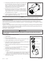
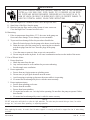
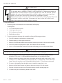
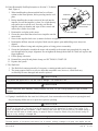
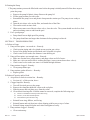
WhisperFlo™ Pump Owner's Manual
IMPORTANT SAFETY INSTRUCTIONS
READ AND FOLLOW ALL INSTRUCTIONS
SAVE THESE INSTRUCTIONS
Table of Contents
SECTION I.
GENERAL INFORMATION ............................................................................................ 2
SECTION II.
MAINTENANCE ......................................................................................................... 3
SECTION III.
SERVICE .................................................................................................................. 5
SECTION IV.
RESTART INSTRUCTIONS ........................................................................................... 6
SECTION V.
TROUBLESHOOTING ................................................................................................. 7
SECTION VI.
TECHNICAL DATA ...................................................................................................... 8
A. REPLACEMENT PARTS ........................................................................................................ 8
B. PUMP CURVES .................................................................................................................. . 9
WARNING
Before installing this product, read and follow all warning notices and instructions accompanying this pump.
Failure to follow safety warnings and instructions can result in severe injury, death, or property damage. Call
(800) 831-7133 for additional free copies of this manual.
Important Notice
Attention Installer.
This manual contains important information about the installation, operation and safe use of this
product. This information should be given to the owner/operator of this equipment.
WARNING
Risk of electrical shock or electrocution.
This pool pump must be installed by a licensed or certified electrician or a qualified pool
serviceman in accordance with the National Electrical Code and all applicable local codes and
ordinances. Improper installation will create an electrical hazard which could result in death or
serious injury to pool users, installers, or others due to electrical shock, and may also cause
damage to property.
Always disconnect power to the pool pump at the circuit breaker before servicing the pump.
Failure to do so could result in death or serious injury to serviceman, pool users or others due to
electric shock.
Pentair Pool Products
1620 Hawkins Ave., Sanford, NC 27330 • (919) 774-4151
10951 West Los Angeles Ave., Moorpark, CA 93021 • (805) 523-2400
Rev. D
6-5-01
Listed
227T
1
Listed
P/N 071109
Note
When pump is mounted permanently within 5 ft. of the inside walls of a swimming pool, you must use a No. 8 AWG or
larger conductor to connect to bonding conductor lug.
WARNING
To reduce the risk of injury, do not permit children to use this product unless they are closely supervised at all times.
CAUTION
This pump is for use with permanently installed pools and may also be used with hot tubs and spas if so marked. Do
not use with storable pools. A permanently installed pool is constructed in or on the ground or in a building such that it
cannot be readily disassembled for storage. A storable pool is constructed so that it may be readily disassembled for
storage and reassembled to its original integrity and has a maximum dimension of 18 feet (5.49m) and a maximum wall
height of 42 inches (1.07m).
CAUTION
For hot tubs and spa pumps, do not install within an outer enclosure or beneath the skirt of a hot tub or spa unless so
marked.
SECTION I.
GENERAL INFORMATION.
A. Wiring.
WARNING
Risk of electrical shock or electrocution.
This pool pump must be installed by a licensed or certified electrician or a qualified pool serviceman in
accordance with the National Electrical Code and all applicable local codes and ordinances. Improper
installation will create an electrical hazard which could result in death or serious injury to pool users,
installers, or others due to electrical shock, and may also cause damage to property.
Always disconnect power to the pool pump at the circuit breaker before servicing the pump. Failure to do
so could result in death or serious injury to serviceman, pool users or others due to electric shock.
1. Make sure all electrical breakers and switches are turned off before wiring motor.
Chart 1.
2. Make sure that the wiring voltage matches the motor
voltage (230v or 115v). If they do not match the
motor will burn up.
3. Choose a wire size from the Chart 1. When in doubt
use a heavier gauge (larger diameter) wire. Heavier
gauge will allow the motor to run cooler and more
efficient.
4. Make sure all electrical connections are clean and
tight.
5. Cut wires to the appropriate length so they don’t
overlap or touch when connected to the terminal
board.
P/N 071109
2
SUPPLY WIRE SIZES (AWG)
(size and length by horsepower)
hp
115 volts
50 ft.
230 volts
100 ft. 150 ft.
50 ft.
100 ft. 150 ft.
1/3
14
14
12
14
14
14
1/2
14
12
10
14
14
14
3/4
12
12
10
14
14
14
1
12
10
8
14
14
14
1½
10
10
8
14
14
12
2
10
8
8
14
12
12
3
-
-
-
12
12
10
Rev. D
6-5-01
6. Permanently ground the motor using the green ground terminal
located on the inside of the motor canopy or access plate, see
Figure 1. Use the correct wire size and type specified by
National Electrical Code. Make sure the ground wire is
connected to an electrical service ground.
7. Bond the motor to the pool structure in accordance with the
National Electrical Code. Use a solid No. 8 AWG or larger
copper conductor. Run a wire from the external bonding to the
pool bonding structure, see Figure 1.
8. Connect the pump permanently to a circuit. Make sure no other
lights or appliances are on the same circuit.
Bonding Lug
Ground Screw
Figure 1.
NOTE
It is important that the O-ring be kept clean and well lubricated. We recommend a silicone base lubricant for best results.
B. The Pump Strainer Basket.
This unit, sometimes referred to as the ‘Hair and Lint Pot’, is the unit in front of the volute. Inside the chamber is the
basket which must be kept clean of leaves and debris at all times. View basket through the ‘See Through Lid’ to inspect
for leaves and debris.
Regardless of the length of time between filter cleaning, it is most important to visually inspect the hair and lint pot basket
at least once a week. A dirty basket will reduce the efficiency of the filter and heater and also put an abnormal stress on
the pump motor which would result in a costly repair bill.
SECTION II. MAINTENANCE.
CAUTION
To prevent damage to the pump and filter and for proper operation of the system, clean pump strainer and skimmer
baskets regularly.
A. Pump Strainer Basket Cleaning Procedures.
1.
2.
3.
4.
5.
Turn off motor.
Relieve pressure in the system.
Turn the clamp and lid in a counter-clockwise direction until it stops.
Turn the clamp and lid set to remove the clamp and lid.
Put the debris from the basket into the trash and rinse out the basket. If
the basket is cracked, it should be replaced.
6. Replace the basket and fill the pump pot and volute up to the inlet port
with water.
7. Clean the cover, cover O-ring, and sealing surface of the pump pot.
Grease the O-ring with Teflon or silicone.
8. Reinstall the lid by placing the clamp and the lid on the pot;
see Figure 2.
Clamp, pot
Lid
O-ring, lid
Basket
Pot
a. Make sure the lid O-ring is properly placed. Seat the clamp and lid
then turn clockwise until the handles are horizontal; see Figure 3.
9. Turn the power “ON” at the house circuit breaker. Reset the pool time
clock to the correct time.
Figure 2.
Rev. D
6-5-01
3
P/N 071109
WARNING
THIS FILTER OPERATES UNDER HIGH PRESSURE. WHEN ANY PART OF THE CIRCULATING
SYSTEM (e.g., LOCK RING, PUMP, FILTER, VALVES, ETC.) IS SERVICED, AIR CAN ENTER
THE SYSTEM AND BECOME PRESSURIZED. PRESSURIZED AIR CAN CAUSE THE LID TO
BLOW OFF WHICH CAN RESULT IN SEVERE INJURY, DEATH, OR PROPERTY DAMAGE. TO
AVOID THIS POTENTIAL HAZARD, FOLLOW THESE INSTRUCTIONS.
10. Open the High Flow™ manual air relief valve on top of the filter.
11. Stand clear of the filter. Start the pump.
12. Bleed air from the filter until a steady stream of water comes out.
Close the High Flow™ manual air relief valve.
B. Winterizing.
1. If the air temperature drops below 35° F. the water in the pump can
freeze and cause damage. Freeze damage is not warrantable.
2. To prevent freeze damage follow the procedures listed below.
Clamp
Lid
Volute
a. Shut off electrical power for the pump at the house circuit breaker.
Figure 3.
b. Drain the water out of the pump case by removing the two thumbtwist drain plugs from the case. Store the plugs in the pump
basket.
c. Cover the motor to protect it from severe rain, snow and ice.
d. Do not wrap the motor in plastic. It will cause condensation and rust on the inside of the motor.
C. Care of Electric Motor.
1. Protect from heat.
a. Shade the motor from the sun.
b. Any enclosure must be well ventilated to prevent overheating.
c. Provide ample cross ventilation.
2. Protect against dirt.
a. Protect from any foreign matter or splashing water.
b. Do not store (or spill) pool chemicals near the motor.
c. Avoid sweeping or stirring up dust near the motor while it is operating.
d. If a motor has been damaged by dirt it voids the motor warranty.
3. Protect against moisture.
a. Protect from splashing pool water.
b. Protect from the weather.
c. Protect from lawn sprinklers.
d. If a motor has become wet - let it dry before operating. Do not allow the pump to operate if it has
been flooded.
e. If a motor has been damaged by water it voids the motor warranty.
NOTE
DO NOT wrap motor with plastic or other air tight materials. The motor may be covered during a storm, for winter
storage, etc., but never when operating, or expecting operation.
NOTE
When replacing the motor, be certain that the motor support is correctly positioned to support the size of motor being
installed.
P/N 071109
4
Rev. D
6-5-01
SECTION III. SERVICE.
WARNING
Risk of electrical shock or electrocution.
This pool pump must be installed by a licensed or certified electrician or a qualified pool serviceman in
accordance with the National Electrical Code and all applicable local codes and ordinances. Improper
installation will create an electrical hazard which could result in death or serious injury to pool users,
installers, or others due to electrical shock, and may also cause damage to property.
Always disconnect power to the pool pump at the circuit breaker before servicing the pump. Failure to do
so could result in death or serious injury to serviceman, pool users or others due to electric shock.
Read all servicing instructions before working on the pump.
A. Pump Disassembly.
1. All moving parts are located in the rear sub-assembly of this pump.
Tools required:
a. 3/32 inch Allen head wrench.
b. ½ inch open end wrench.
c. 9/16 inch open end wrench.
d. Flat blade screwdriver.
2. To remove and repair the motor sub-assembly perform the following procedures.
a. Turn off the pump circuit breaker at the main panel.
b. Drain the pump by removing the drain plugs.
c. Remove the 6 bolts that hold the main pump body (strainer pot/volute) to the rear sub-assembly.
d. GENTLY pull the two pump halves apart, removing the rear sub-assembly.
e. Use a 3/32 inch Allen head wrench to loosen the two holding screws located on the diffuser.
CAUTION
Be sure not to scratch or mar the polished shaft seal faces; seal will leak if faces are damaged.
f. Hold the impeller securely in place and remove the impeller lock screw by using a flat blade
screwdriver. The screw is a left-handed thread and loosens in a clockwise direction.
g. Remove the shaft cap located at the back of the motor and hold the shaft secure with a ½ inch
(Century) or 7/16 inch (Franklin) open-end wrench. On A. 0. Smith motors, remove the motor
canopy, move the capacitor to one side and hold the shaft with a 7/16 inch open-end wrench.
h. To unscrew the impeller from the shaft, twist the impeller counterclock- wise.
i.
Remove the four bolts from the seal plate to the motor, using a 9/16 inch wrench.
j.
Place the seal plate face down on a flat surface and tap out the carbon/spring seat.
k. Clean the seal plate, seal housing, and the motor shaft.
Rev. D
6-5-01
5
P/N 071109
B. Pump Reassembly/Seal Replacement; see Section V, Technical
Data, Figure 4.
Bolt
1. When installing the replacement shaft seal, use silicone
Seal Plate
sealant on the metal portion, before pressing into the seal
plate.
Gasket
2. Before installing the ceramic section of the seal into the
impeller, be sure the impeller is clean. Use a light density
Lockscrew
Water Slinger
soap and water to seal the seal. Press the seal into the
Motor
Shaft
impeller with your thumbs and wipe off the ceramic and
carbon faces with a clean cloth.
Impeller
Lockscrew Seal
3. Remount the seal plate to the motor.
4. Grease the motor shaft thread and screw impeller onto the
Figure 4.
motor shaft.
5. Screw in the impeller lock screw (counter-clockwise to tighten).
6. Remount the diffuser onto the seal plate. Make sure the plastic pins and holding screw inserts are
aligned.
7. Grease the diffuser O-ring and seal plate gasket or O-ring prior to reassembly.
8. Grease the bolt threads, assemble the motor sub-assembly to the strainer pot-pump body by using the
two through bolts for proper alignment. Do not tighten the through bolts until all 6 bolts are in place and
finger tightened.
9. Fill the pump with water.
10. Reinstall the pump lid and plastic clamp; see SECTION II. START-UP.
11. Reprime the system.
C. The Shaft Seal.
1. The Shaft Seal consists primarily of two parts, a rotating member and a ceramic seal.
2. The pump requires little or no service other than reasonable care, however, a Shaft Seal may
occasionally become damaged and must be replaced.
CAUTION
The polished and lapped faces of the seal could be damaged if not handled with care.
CAUTION
In mild climate area, when temporary freezing conditions may occur, run your filtering equipment all night to prevent
freezing.
SECTION IV. RESTART INSTRUCTIONS.
A. If pump is installed below the water level of the pool, close return and suction lines prior to opening hair and
lint pot on pump. Make sure to re-open valves prior to operating.
CAUTION
DO NOT run the pump dry. If the pump is run dry, the mechanical seal will be damaged and the pump will start leaking. If this
occurs, the damaged seal must be replaced. ALWAYS maintain proper water level in your pool (half way up skimmer opening). If
the water level falls below the skimmer opening, the pump will draw air through the skimmer, losing the prime and causing the
pump to run dry, resulting in a damaged seal.
Note
Continued operation in this manner could cause a loss of pressure, resulting in damage to the pump case, impeller and seal.
P/N 071109
6
Rev. D
6-5-01
B. Priming the Pump.
1. The pump strainer pot must be filled with water before the pump is initially started. Follow these steps to
prime the pump.
a. Remove the pump lid plastic clamp. Remove the pump lid.
b. Fill the pump strainer pot with water.
c. Reassemble the pump cover and plastic clamp onto the strainer pot. The pump is now ready to
prime.
d. Open the air release valve on the filter, and stand clear of the filter.
e. Turn on the switch or time clock.
f. When water comes out of the air release valve, close the valve. The system should now be free of air
and recirculating water to and from the pool.
2. For 2-speed pumps:
a. Pump should run on high-speed for priming.
b. The pump should not run longer than 8 minutes before priming is achieved.
SECTION V. TROUBLESHOOTING.
A. Failure to Pump.
1. Pump will not prime - too much air. - Remedy:
a. Check suction piping and valve glands on any suction gate valves.
b. Secure lid on pump strainer pot and make sure lid gasket is in place.
c. Check water level to make sure skimmer is not drawing air.
2. Pump will not prime--not enough water. - Remedy:
a. Make sure suction lines, pump strainer, and pump volute are full of water.
b. Make sure valve on suction line is working and open, (some systems do not have valves).
c. Check water level to make sure water is available through skimmer.
3. Pump strainer clogged. - Remedy:
a. Clean pump strainer pot.
4. Pump strainer gasket defective. - Remedy:
a. Replace gasket.
B. Reduced Capacity and/or Head.
1. Air pockets or leaks in suction line. - Remedy:
a. See item A.1. of this section, above.
2. Clogged impeller. Remedy:
a. Turn off electrical power to the pump.
b. Remove the clamp that holds the volute to the seal plate.
c. Slide the motor and seal plate away from the volute.
d. Clean debris from impeller. If debris cannot be removed, complete the following steps.
(1)
(2)
(3)
Remove left hand thread anti-spin bolt and O-ring.
Remove, clean and reinstall impeller.
Reinstall anti-spin bolt and O-ring.
e. Reinstall wear-ring, diffuser, and O-ring.
f. Reinstall motor and seal plate into volute aligning with keyway at top of volute.
g. Reinstall clamp around seal plate and volute and tighten securely.
3. Pump strainer clogged. - Remedy:
a. Clean suction trap.
Rev. D
6-5-01
7
P/N 071109
SECTION VI. TECHNICAL DATA.
26
28
27
A. Replacement Parts.
Item
No.
Part
No.
Model
No.
Description
Item
No.
Part
No.
Model
No.
Description
1
357150
CLAMP POT (Black)
1
357199
CLAMP POT (Almond)
2
07-0795
2
357151
3
350013
4
07-0387
P01325
5
07-0430
P02812
BOLT 3/8 16 X 1.15 HEX HD s/s, 4 req.
6
07-2184
P35011
Wsh. 3/8 s/s X 13/16 O.D. 6
7
07-0431
P02813
BOLT 3/8 - 16 X 1/75 HX HD s/s, 2 req.
8
07-1403
P23696
07-1313
P21258
.75 HP 60HZ /WFE-2, 3 & 24, 29 Lbs.
9
357102
GASKET SEAL PLATE WFE PUMP
07-1314
P21259
1 HP 60HZ /WFE-4 & 26, 33 Lbs.
P08080
20
07-0929
20a
357160
P10313
FOOT INSERT WFE PUMP
FOOT INSERT (CANADA ONLY)
COVER LEXAN AQ/WFE PUMP
21
07-1657
P26948
SCREW ¼ - 20 X 1 in. HH s/s, 2 req.
COVER LEXAN WFE PUMP
22
07-1406
P23802
NUT ¼ - 20 HEX. hd. s/s, 2 req.
O-RING WFE COVER
23
07-2183
P35010
Wsh. FLAT ¼ X 5/8 , 2 req.
BASKET AQ & WFE
24
07-1131
P19656
24a
357161
25
07-4629
KNOB PLUG DRAIN, 2 req.
KNOB, DRAIN (CANADA ONLY)
GASKET, FLAT Wsh. WFE PMP. DRN., 2 req.
ITEM 26, MOTORS
NUT 3/8 - 16 HEX. hd., 2 req.
26
10
350015
VOLUTE WFE PUMP & POT
07-1315
P21260
1.5 HP 60HZ /WFE-6 & 28, 39 Lbs.
10a
357157
VOLUTE (CSA/CUL ONLY) CANADA
07-1316
P21261
2 HP 60HZ /WFE-8 & 30, 40 Lbs.
11
07-1444
P24262
O-RING PARKER #2-238 WFE PUMP
27
12
07-1660
P26951
SET SCREW #4-40 X 1-1/8 WFE, 2 req.
28
13
07-2928
S05633
DIFFUSER assy. WFE 12/3 HP ONLY
07-2927
S05632
DIFFUSER assy. WFE-3 & 8, 75 HP – 2.5 HP
14
07-1652
P26942
SET SCREW .25 20 X 1 LH PHILLIPS
15
07-5713
16
07-1734
16a
07-1728
17
07-0429
18
SEAL A7 s/s PS201 (CSA/CUL)
BOLT 3/8-16 X 7/8 s/s HEX hd., 4 req.
07-3742
SEAL PLATE WFE - NOT AVAILABLE
07-4564
SEAL PLATE WFE
357173
19
07-0927
19a
357159
P/N 071109
SEAL PA-7 W/CERAMIC SEAT
P02811
SEAL PLATE / CUP (CSA/CUL)
P10311
VOLUTE REPLACEMENT KIT
27 IMPELLER CHART
WFE PUMP RUBBER Wsh.
P28323
IMPELLER (SEE CHART)
357149
FOOT WFE - 4 PUMP
FOOT (CANADA ONLY)
8
HP
SIZE
STD
PART NO.
CANADIAN
CSA/CUL
½
WF, WFE-2, -23
073126
357167
¾
WF, WFE-3, -24
073127
357168
1
WF, WFE-4, -26
073128
357169
1½
WF, WFE-6, -28
073129
357170
2
WF, WFE-8, -30
073130
357171
3
WFE-12
073131
357172
Rev. D
6-5-01
B. Pump Curves.
Dual Speed Models
Single Speed Models
SAVE THESE INSTRUCTIONS.
Rev. D
6-5-01
9
P/N 071109
Pentair Pool Products WhisperFlo™
Circulating Pump Limited Warranty
Pentair Pool Products manufactures its WhisperFlo circulating
pumps under high standards of workmanship and with high
quality materials. Accordingly, Pentair Pool Products expressly
warrants those pump models as follows:
WARRANTY COVERAGE - All pump component parts
actually manufactured by Pentair Pool Products, and the
pump’s respective motor is warranted to be free from defects in
material and/or workmanship for a period of three (3) years from
date of purchase. The obligation of Pentair Pool Products
under this warranty will be limited to either repair or
replacement of the product, at Pentair Pool Products option.
EXCLUSIONS FROM THIS WARRANTY - This warranty does
not cover:
1. Any item manufactured by other companies and installed
by Pentair Pool Products. Such items may carry warranties
offered by the original manufacturer.
2. Problems resulting from oversizing of pump and/or
reduction of valve piping size, or from failure to turn pump
off before changing the position of the filter valve or any
operating valves for the pool and its accessories.
3. Problems resulting from failure to comply with instructions
contained in the Owner's Manual.
4. Problems resulting from abuse, misuse, negligence or
accident by any party other than Pentair Pool Products,
such as but not limited to, damage to parts caused by
installers, damage to pump parts caused by ‘dry’ operation
(loss of prime or obstruction in plumbing lines).
Pentair Pool Products is not, however responsible under
this warranty for any cost of shipping or transportation of
the filter or part thereof to or from the service department.
Also, Pentair Pool Products is not liable for any loss of time,
inconvenience, incidental expenses such as telephone calls,
labor or material charges incurred in connection with the
removal or replacement of the equipment, or any other
incidental or consequential damages. PLEASE NOTE: Some
states do not allow the exclusion or limitation or incidental
or consequential damages, so the above limitation or
exclusion may not apply to you.
PROCEDURE FOR OBTAINING PERFORMANCE: In order
to obtain the benefits of this warranty the consumer who
made the original retail purchase will contact Pentair Pool
Products Customer Service Department, 10951 W. Los
Angeles Ave., Moorpark, CA 93021 as soon as possible
after discovery of the defect, but in no event later than the
expiration date of the warranty period provided in this
warranty. Upon receipt of this communication, Pentair Pool
Products will promptly notify the customer of the address to
which the defective item may be shipped. The customer
shall then ship the item, freight prepaid, to the address
indicated together with a letter stating the model number,
serial number, and the date of purchase of the item which is
claimed to be defective, and the name and address of the
consumer and a brief description of the problems
encountered.
WARRANTY PROTECTS ORIGINAL PURCHASER: This
warranty extends to the consumer who made the original
retail purchase only and is not enforceable by any other
party.
5. Problems resulting in whole or in part from alteration or
modification of the filter by any party.
6. Failures due to chemical corrosion caused by failure to
maintain the water chemistry in conformity with the
standard of the swimming pool and spa industry.
WARRANTY OBLIGATIONS OF PENTAIR POOL
PRODUCTS - Should a defect in workmanship and/or material
in any item covered by this warranty become evident during
the term of the warranty, then upon the consumer following the
procedures set forth below, Pentair Pool Products will, at its
option, repair or replace such item or part at its own cost and
expense.
WARRANTIES OR REPRESENTATIONS BY OTHERS: No
dealer or other person has any authority to make any
warranties or representations concerning Pentair Pool
Products or its products. Accordingly, Pentair Pool
Products is not responsible for any such warranties or
representations.
OTHER RIGHTS: This warranty gives you specific legal
rights and you may also have other rights which vary from
state to state.
Pentair Pool Products
1620 Hawkins Ave., Sanford, NC 27330 • (919) 774-4151
10951 West Los Angeles Ave., Moorpark, CA 93021 • (805) 523-2400
P/N 071109
10
Rev. D
6-5-01