1
PowerPro Series
PS-200 PS-400 PS-800 PS-1400
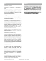
Precauciones de Seguridad
Safety Precautions
El signo de exclamación dentro de un triángulo indica la existencia
de componentes internos cuyo reemplazo puede afectar a la
seguridad.
The exclamation point inside an equilateral triangle indicates the
existence of internal components whose substitution may affect
safety.
El signo del rayo con la punta de flecha alerta contra la presencia de
voltajes peligrosos no aislados. Para reducir el riesgo de shock
eléctrico, no retire la cubierta.
The lightning and arrowhead symbol warns about the presence of
uninsulated dangerous voltage. To reduce the risk of electric shock,
do not remove the cover.
Los signos de rayo cerca de los terminales de Salida del
amplificador alertan del riesgo de choque eléctrico en condiciones
normales de uso (terminales peligrosos al tacto).
No toque dichos terminales mientras el amplificador esté encendido.
The lightning and arrowhead symbol near the output terminals of
the amplifier alert of the risk of electric shock in normal conditions
of use (terminal dangerous to the tact). Do not touch these
terminals while the amplifier is working.
El cableado exterior conectado a estos terminales requiere de su
instalación por una persona instruida o el uso de cables flexibles
ya preparados.
The connected outer wiring to these terminals requires of its
installation by an instructed person and the use of a flexible
the cable already prepared.
Este símbolo en su equipo indica que el presente producto no puede
ser tratado como residuos domésticos normales, sino que deben
entregarse en el correspondiente punto de recogida de equipos
eléctricos y electrónicos.
This symbol on the product indicates that this product should not
be treated as household waste. Instead it shall be handed over to
the applicable collection point for the recycling of electrical and
electronic equipment.
Aparato de Clase I.
Class I device.
La posición de encendido está indicada en el interruptor mediante
los correspondientes símbolos normalizados (UNE EN 60417 partes
1 y 2 de 2002) y dos LEDs encendidos cerca del interruptor.
The ON position is indicated in the switch by means of the
corresponding standardized symbols (UNE 60417 parts 1 and 2 of
2002) and two red LEDs located near the switch.
Si el aparato es conectado permanentemente, la instalación
eléctrica del edificio debe incorporar un interruptor multipolar con
una separación de contacto de al menos 3mm en cada polo.
If the apparatus is connected permanently, the electrical system of
the building must incorporate a multipolar switch with a separation
of contact of at least 3mm in each pole.
Conserve estas instrucciones. Siga todas las advertencias. Lea
todas las instrucciones.
Keep these instructions. Heed all warnings. Follow all instructions.
No exponga este equipo a la lluvia o humedad. No use este aparato
cerca del agua - piscinas, fuentes, por ejemplo. No exponga el
equipo a salpicaduras ni coloque sobre él objetos que contengan
líquidos, tales como vasos o botellas.
Do not expose this device to rain or moisture. Do not use this
apparatus near water - for example, swimming pool, fountain. Do
not place any objects containing liquids, such as bottles or glasses,
on the top of the unit. Do not splash liquids on the unit.
Limpie el aparato sólo con un paño seco. No use limpiadores
basados en disolventes.
Clean only with a dry cloth. Do not use any solvent based cleaners.
No instale el aparato cerca de ninguna fuente de calor como
radiadores, estufas u otros aparatos que produzcan calor.
Do not install near any heat sources such as radiators, heat
registers, stoves, or other apparatus that produce heat.
Desconecte este aparato durante tormentas eléctricas, terremotos
o cuando no se vaya a emplear durante largos periodos.
Unplug this apparatus during lightning storms, earthquakes or when
unused for long periods of time.
No existen partes ajustables por el usuario en el interior de este
equipo. Cualquier operación de mantenimiento o reparación debe
ser realizada por personal cualificado. Es necesario el servicio
técnico cuando el aparado se haya dañado de alguna forma, tal
como que el cable de corriente o el enchufe se hayan dañado, haya
caído líquido o algún objeto en el interior del aparato, el aparato
haya sido expuesto a lluvia o humedad, no funcione correctamente
o haya recibido un golpe.
No user serviceable parts inside. Refer all servicing to qualified
service personnel. Servicing is required when the apparatus has
been damaged in any way, such as power-supply cord or plug is
damaged, liquid has been spilled or objects have fallen into the
apparatus, the apparatus has been exposed to rain or moisture,
does not operate normally, or has been dropped.
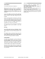
B) INDICADORES LED DE ENCENDIDO DEL
AMPLIFICADOR (POWER)
Cuando estos indicadores luminosos verdes están
iluminados nos indica que ambos canales de amplificación
preparados para el uso.
PRESENTACIÓN
Generalidades
Gracias por adquirir un amplificador D.A.S. Los
amplificadores de potencia D.A.S. están construidos con la
más avanzada tecnología modular y han sido diseñados en
su totalidad con sistemas asistidos por ordenador, tanto
sus partes mecánicas como las electrónicas.
C) CONTROLES DE NIVEL (LEVEL)
El volumen (ganancia de entrada) de cada canal puede ser
ajustado independientemente por medio de estos
controles. La ganancia máxima se consigue cuando el
potenciómetro rotatorio LEVEL se gira completamente en
sentido horario.
Características
•
•
•
•
•
•
•
•
•
•
•
•
•
Clase AB.
Fuente de Alimentación lineal.
Entradas dobles balanceadas XLR (Cannon).
Salidas por bornas y speakon (sólo en PS-800 y PS1400).
Ventilación forzada con velocidad variable de atrás
hacia delante.
Control de volumen frontal para cada canal.
Sensibilidad seleccionable entre 0.775V, 1V y 1.44V.
Switch anti-bucles de tierra.
Modo de funcionamiento seleccionable entre estéreo,
paralelo y puente.
Protección totales en cada salida amplificada tanto
contra cortocircuitos como contra excesiva carga en
la salida, así como detectores de temperatura
independientes para cada canal.
Protección total en la fuente de alimentación frente a
sobre-corriente, sobre-tensiones y cortocircuito con
activación al modo standby de funcionamiento frente
a una sobre carga en corriente.
Limitación anti-clip.
Indicadores LED
de verdadero recorte (clip),
protección, presencia de señal y encendido para cada
canal.
D) INDICADOR LED DE RECORTE (CLIP)
Cuando alguno de los canales entra en saturación, debido
a que la excursión de la señal supera la máxima tensión
que puede suministrar la fuente de alimentación del
amplificador, el correspondiente LED (indicador luminoso)
rojo del canal se enciende durante unos instantes,
indicándonos de esta manera que la etapa de potencia
entra en saturación. En este momento el limitador
comienza a actuar corrigiendo el nivel de la señal.
E) INDICADORES LED DE PROTECCIÓN (PROTECTION)
Este LED amarillo se enciende cuando la salida de un canal
está desactivada por la protección del amplificador.
El circuito puede entrar en funcionamiento en las
siguientes situaciones :
• Cuando se detecta exceso de temperatura en un
canal del amplificador. La salida vuelve a activarse
cuando desaparece el exceso de temperatura. El
circuito de control del activado del canal posee una
cierta histéresis para impedir la aparición de
oscilaciones en la conexión y desconexión.
• Cuando se detecta corriente continua en un canal de
amplificador. Ésta es muy peligrosa para los altavoces
y por ello, cuando supera cierto umbral, la salida
también es desactivada. La salida vuelve a activarse
cuando desaparece la corriente continua.
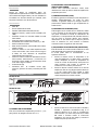
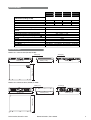
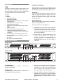
DESCRIPCIÓN DEL PANEL FRONTAL
PS-200, PS-400
Level A
Clip
Protection
ELECTRONICS
PS-400
Clip
On
On
PS-800, PS-1400
G
D
C F B
®
ELECTRONICS
Level B
Protection
Signal
Signal
PowerPro Series
A E
PS-800
Clip
Clip
Protection
Protection
Signal
Signal
On
Level A
On
Level B
PowerPro Series
G
D
C
F B
A) INTERRUPTOR DE ENCENDIDO
Pone en funcionamiento el amplificador (posición " I "), o lo
para (posición de apagado marcada como " 0 ").
Serie PowerPro/ PowerPro series
A
E
•
Cuando se detecta un cortocircuito (sólo en PS-200 y
PS-400), o impedancia anormalmente baja en la
salida de altavoces de un canal. Si el amplificador
está encendido y se activa esta protección, la salida
NO vuelve a activarse cuando el cortocircuito
desaparece, sino que hay que apagar y encender el
amplificador para que esto ocurra.
Manual del usuario / User's manual
1
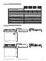
B) ENTRADAS
Se dispone de entradas XLR y Jack en cada canal del
amplificador.
La impedancia nominal de entrada es de 20k ohmios en
modo balanceado y 10k ohmios en modo no-balanceado.
La polaridad sigue la norma AES14-1992 (ANSI S4.481992):
Pin 1 en XLR o ‘Sleeve’ en Jack. GND (Masa)
Pin 2 en XLR o ‘Tip’ en Jack. (+) Entrada no
invertida
Pin 3 en XLR o ‘Ring’ en Jack. (–) Entrada
invertida
En el encendido del amplificador, para evitar que el
transitorio pueda dañar los altavoces y el molesto ruido
que produce, la salida también se desactiva y la luz de
PROTECTION se enciende.
F) INDICADORES LED DE PRESENCIA DE SEÑAL
(SIGNAL)
Estos LED de color verde nos indican la presencia de señal
en las entradas de los canales de amplificador y son
dependientes de la posición de los controles LEVEL de
volumen.
G) REJILLAS DE VENTILACIÓN
Por ellas se desaloja el aire del interior que se ha hecho
circular por los radiadores de los módulos de potencia.
Debe intentarse siempre que estén libres de polvo y
suciedad, así como procurarse que nada impida la libre
circulación de aire.
C) CONMUTADOR DE MODO DE FUNCIONAMIENTO
Un interruptor permite conmutar entre modo estéreo,
paralelo o puente.
El modo estéreo es el habitual de un amplificador y el que
está ajustado por defecto, de manera que la señal de
entrada A alimenta el canal A y la señal de entrada B el
canal B.
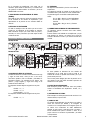
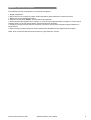
DESCRIPCIÓN DEL PANEL POSTERIOR
PS-200, PS-400
COLD
HOT
COLD
STEREO
CH A INPUT
FOR CONTINUED PROTECTION AGAINST RISK OF FIRE, REPLACE ONLY WITH THE SAME FUSE TYPE
F
PS-800, PS-1400
SPEAKER OUTPUT
SENSITIVITY GROUND S.N.
1.44V
OFF
MODEL: PS-400
230V
50/60Hz 5A
OUTPUT PWR PER CH: 200W@4
D.A.S. AUDIO S.A. , SPAIN
MADE IN CHINA
0.775V
ON
2
BRIDGE
CH A
1.0V
PARALLEL
GND
C
3
GND
N1918
1
D E
B
CH B INPUT
CH B
S.N.
GROUND
OFF
MODEL: PS-800
230V
10A 50Hz/60Hz
OUTPUT PWR PER CH: 390W@4
ON
N1918
FOR CONTINUED PROTECTION AGAINST RISK
OF FIRE REPLACE ONLY WITH THE SAME TYPE
F 10A L 250V FUSE
3
HOT
1
CH B
PARALLEL
GND
CH A INPUT
SENSITIVITY
SPEAKER OUTPUT
1.0V
0.775V
1.44V
CAUTION
RISK OF ELECTRIC SHOCK
DO NOT OPEN
ATTENTION
DANGER D’ELECTROCUTION
NE PAS OUVRIR
WARNING: TO REDUCE RISK OF FIRE OR ELECTRIC SHOCK
DO NOT EXPOSE THIS EQUIPMENT TO RAIN OR MOISTURE
D.A.S. AUDIO S.A. (VALENCIA) SPAIN
MADE IN CHINA
F
B
1+ 1-
COLD
VER MANUAL DE INSTRUCCIONES PARA LA CONEXIÓN
REFER TO INSTRUCTIONS MANUAL FOR CONNECTION
ANSCHLUSSWEISE BITTE DER ANLEITUNG ENTNEHMEN
VOIR MANUEL D'INSTRUCTIONS POUR LA CONNEXION
E
D
C
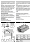
A) SALIDAS DE LÍNEA DE ALTAVOCES
La salida de altavoces se realiza a través de las bornas roja
y negra de cada canal, o bien por uno o dos de los
conectores Speakon (sólo en PS-800 y PS-1400). Es
importante atender a la polaridad de las bornas, roja
positivo y negra negativo, y seguir este código en la
instalación de los altavoces.
En el Speakon situado abajo las asignaciones de pines
son:
Canal A : +1 / -1
Canal B : +2 / -2
Puente (bridge) : +1 /+2
En el Speakon situado arriba las asignaciones de pines
son:
Canal B : +1 / -1
CH A
1+ 1CH B
2+ 2BRIDGE 1+ 2+
CH A
GND
BRIDGE
2
BRIDGE
MODE STEREO
HOT
COLD
G
A
CH B
F 5A L 250V FUSE
HOT
CH B INPUT
BRIDGE
A
G
En modo paralelo se alimentan los dos canales del
amplificador con la señal que le entra al canal A. La
entrada del canal B no quedará desconectada, por lo que
puede usarse para ‘link’.
Use el modo puente (bridge) para usar la potencia de los
dos canales en una sola salida. Consulte el apéndice de
utilización en modo puente.
D) SELECTOR DE SENSIBILIDAD
Este interruptor permite seleccionar entre tres posibles
valores la sensibilidad del amplificador: 0.775V, 1V y
1.44V.
E) INTERRUPTOR DE TIERRA
Este interruptor se utiliza para evitar bucles de tierra. Si se
detecta el bucle, se pone a ‘OFF’.
F) CABLE DE RED
La conexión del amplificador a la red eléctrica se realiza a
través del conector tipo IEC320, y su manguera de
conexión a red correspondiente. Esta manguera posee en
su interior tres conductores de cable debidamente
aislados, de color marrón y azul para la fase y el neutro, y
bicolor amarillo-verde para la conexión a tierra. En el
propio conector se encuentra el portafusible y el fusible
correspondiente.
Serie PowerPro/ PowerPro series
Manual del usuario / User's manual
2
Se pueden usar las bornas bien pelando los cables de cada
cable de altavoz e introduciéndolos por el orificio de las
bornas y luego apretándolas, o bien empleando conectores
tipo banana. En cualquier caso pele solamente la longitud
de camisa del cable que permita que el conductor quede
oculto. Observe la polaridad (rojo = +, negro = –).
G) REJILLAS DE ENTRADA DE AIRE
Como en el caso de las rejas de la parte frontal, deben
estar siempre libres de obstrucción, polvo u objetos que
impidan la libre circulación de aire.
INSTALACIÓN
Alternativamente, pueden usarse los conectores Speakon,
que aportan la ventaja de proporcionar una conexión y
desconexión rápida para aplicaciones portátiles. Para
activar la conexión se ha de insertar el conector macho en
el hembra y rotar el primero en sentido horario, quedando
bloqueado.
Montaje
Los amplificadores están diseñados para ser montados en
un rack estándar de 19 pulgadas. Su altura es de 2
unidades DIN en el caso de PS-800 y PS-1400 y de 1
unidad DIN en el caso de PS-200 y PS-400.
En los Apéndices de este manual se adjunta una tabla para
ayudar en la elección del cable adecuado.
Para su montaje dispone de cuatro colisos (perforaciones
alargadas) en la carátula, de los que puede ser sujeto al
rack por tornillos de métrica cinco o seis. Para evitar la
deformación del chasis en aplicaciones de rack en las que
éste sea transportado, será necesario fijar los
amplificadores utilizando los colisos de refuerzo trasero.
Alternativamente, podremos apoyar el amplificador de
abajo contra la base del rack y apilar los amplificadores sin
espacio entre ellos.
Las
dimensiones
de
los
amplificadores pueden encontrarse
en la sección “Dibujos de línea”.
Ventilación
Conexión a la red eléctrica
La tensión nominal de funcionamiento es 230 V AC. Las
versiones para exportación pueden operar a una tensión
nominal de 115V AC. En ambos casos la tensión de
funcionamiento estará indicada en el panel posterior.
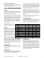
Consumos eléctricos / Power consumption (Amperios / Amperes)
PS-200
Potencia / Power
Max
1/3
1/8
8+8 ohm
4+4 ohm
Puente/bridge 8 ohm
0.87
1.57
1.6
0.31
0.57
0.6
0.15
0.25
0.25
Sin señal
idle
0.05
0.05
0.05
8 ohm
1.64
2.98
3.0
0.57
1.06
1.1
0.27
0.47
0.5
0.08
0.08
0.08
8 ohm
2.8
5.28
5.3
0.98
1.82
1.85
0.48
0.81
0.85
0.15
0.15
0.15
8 ohm
5.2
9.59
9.6
1.82
3.41
3.45
0.84
1.48
1.5
0.2
0.2
0.2
Los amplificadores están diseñados
de forma que radian el calor de su
PS-400
8+8 ohm
4+4 ohm
interior por un sistema de
Puente/bridge
refrigeración por ventilación forzada.
Para ello disponen de radiadores de
PS-800
8+8 ohm
aluminio que son soplados por
4+4 ohm
ventiladores colocados en la parte
Puente/bridge
posterior del amplificador. El aire
PS-1400 8+8 ohm
circula de la parte posterior a la
4+4 ohm
frontal.
Puente/bridge
En caso de montar el amplificador
en un rack, no es necesario que
éste disponga de ventilación forzada, pues el aire circulará
del exterior hacia el interior impulsado por el ventilador del
amplificador, aunque sí es necesario que el rack no esté
cerrado herméticamente. Debe pues disponer de al menos
una rejilla lo suficientemente amplia que permita la entrada
de aire a su interior.
Cableado de entrada
El Apéndice sobre cableado de entrada muestra la
conexión balanceada y no-balanceada desde diversos
tipos de conectores.
Cableado de salida
Consumos eléctricos
Pueden verse para 230V en la tabla que se adjunta.
Multiplique por 2 para conseguir la corriente a 115V.
Las agencias internacionales de normativas de seguridad
especifican el consumo de corriente utilizando ruido rosa a
1/8 del nivel máximo de salida. Esto se hace para
representar la corriente requerida para reproducir un
programa musical típico. La cifra de 1/3 de potencia
representa el consumo eléctrico en el peor caso, mientras
que la cifra de máxima potencia representa el consumo
con señal senoidal a máxima potencia, circunstancia que
nunca se produce en la práctica.
Para la conexión de las salidas se pueden usar las bornas
o bien uno o dos conectores Speakon (sólo en PS-800 y
PS-1400). Observe la indicaciones de la etiqueta.
Serie PowerPro/ PowerPro series
Manual del usuario / User's manual
3
USO
GARANTÍA
ENCENDIDO / APAGADO
Todos nuestros artículos están garantizados por un periodo
de 24 meses. Las garantías sólo serán válidas si son por
un defecto de fabricación y EN NINGÚN CASO POR UN
USO INCORRECTO DEL PRODUCTO. La reparación EN
GARANTÍA cubre la reposición de las partes defectuosas.
Otros cargos como PORTES, SEGUROS, ETC. son a cargo
del comprador en todos los casos. Para solicitar
reparación en garantía es imprescindible que el producto
NO HAYA SIDO PREVIAMENETE MANIPULADO e incluir
una FOTOCOPIA DE LA FACTURA DE COMPRA.
El interruptor de encendido pone en funcionamiento la
etapa.
Al accionarlo (posición "|") se encenderán los led
‘Protection’, pocos segundos después, se producirá la
activación de los canales del amplificador encendiéndose
los led de ‘ON’ y apagándose los ‘Protection’ y la etapa
estará lista para el funcionamiento.
El apagado de la etapa se producirá actuando de nuevo
sobre el interruptor de encendido (posición "0"). En este
momento desaparecerán las tensiones principales de
alimentación del amplificador más las tensiones
secundarias de funcionamiento.
El encendido de un sistema de sonido ha de hacerse de
atrás hacia delante. Encienda el amplificador lo último en
su sistema de sonido. Encienda primero las fuentes tales
como reproductores de CD o platos giradiscos, luego el
mezclador, después los procesadores y divisores de
frecuencia y finalmente los amplificadores. Si tiene varios
amplificadores evite encenderlos todos a la vez.
Enciéndalos secuencialmente uno a uno o instale un
secuenciador automático de encendido.
Al apagar el sistema de sonido siga el proceso inverso, y
apague los amplificadores antes que cualquier otro
elemento del sistema.
INDICADOR LED DE RECORTE (CLIP)
La luz roja del LED de recorte CLIP no debe permanecer
encendida de forma continuada. Esta situación no
perjudica al amplificador, aunque distorsiona la señal y
puede dañar los altavoces. De hecho, la forma más rápida
de quemar la bobina de un altavoz es recortar (saturar,
llevar en clip) de forma considerable. El amplificador
integra una protección contra el recorte continuado,
aunque su eficacia no es total con señal musical. Por ello
se recomienda que si el amplificador entra en clip lo haga
de forma esporádica, y que el LED de recorte nunca esté
encendido de forma continua.
CONTROLES DE NIVEL
Los controles de nivel LEVEL nos permiten cambiar la
ganancia de entrada de la señal. Aunque están
relacionados con la potencia de salida, no son una
representación directa de ésta. Podemos tener máxima
salida de potencia con estos potenciómetros a la mitad.
De igual manera podemos infrautilizar el amplificador
teniendo los volúmenes al máximo si la señal de entrada
(por ejemplo del mezclador) no es lo suficientemente
fuerte.
Una posibilidad de uso de los controles de volumen es
situarlos en una posición tal que cuando el mezclador está
al máximo, no consigamos que las luces de CLIP se
enciendan o lo hagan sólo muy ocasionalmente.
Serie PowerPro/ PowerPro series
Manual del usuario / User's manual
4
ESPECIFICACIONES
Potencia EIA ambos canales / EIA Power, both
channels driven (1 kHz @ 1% THD)
8 ohm, estéreo / stereo
4 ohm, estéreo / stereo
8 ohm, puente / bridge
Distorsion (típica) / Distortion (typical) (20-20k Hz)
Distorsión de Intermodulación / Intermodulation
Distortion
Velocidad de Salto / Rise Time
Respuesta en frecuencia / Frequency Response
Factor de amortiguamiento / Damping Factor (8 Ω)
Relación Señal-Ruido / Signal to Noise (20 Hz-20 kHz)
Crosstalk
Impedancia de entrada / Input Impedance
Topología / Topology
Peso / Weight
Dimensiones / Dimensions
PS-200
PS-400
PS-800
PS-1400
70 W
100 W
200 W
140 W
200 W
400 W
250 W
400 W
800 W
450 W
700 W
1400W
<0.5%
<0.5%
25 V/us
20Hz – 20kHz +1/-1dB
>100
>90dB
>60dB
10K Ohm no bal./unbal., 20K Ohm bal.
Clase AB / Class AB
12 kg (26.4 lb) 13 kg (28.6 lb) 18 kg ( 39.6 lb) 21 kg ( 46lb)
Véase sección Dibujos de línea / See Line Drawings section
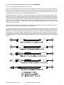
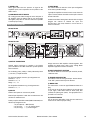
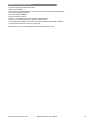
DIBUJOS DE LÍNEA
Modelos de 1 unidad de altura (PS-200, PS-400):
44mm [7/4”]
PS-400
Clip
HOT
Level B
Protection
Signal
On
On
COLD
CH B INPUT
BRIDGE
CH A INPUT
PowerPro Series
HOT
COLD
STEREO
FOR CONTINUED PROTECTION AGAINST RISK OF FIRE, REPLACE ONLY WITH THE SAME FUSE TYPE
482.6mm [19”]
SENSITIVITY GROUND S.N.
1.44V
OFF
MODEL: PS-400
230V
50/60Hz 5A
OUTPUT PWR PER CH: 200W@4
D.A.S. AUDIO S.A. , SPAIN
MADE IN CHINA
0.775V
ON
GND
1.0V
ELECTRONICS
Signal
PARALLEL
Protection
F 5A L 250V FUSE
Clip
Level A
33mm [5/4”]
348mm [13 2/3”]
3
GND
SPEAKER OUTPUT
BRIDGE
CH A
CH B
2
N1918
1
464mm [18 1/4”]
RISK OF ELECTRIC SHOCK
DO NOT OPEN
DANGER D’ELECTROCUTION
NE PAS OUVRIR
ATTENTION
386mm [15 1/5”]
CAUTION
Modelos de 2 unidades de altura (PS-800, PS-1400):
PS-800
Signal
On
CH B INPUT
S.N.
GROUND
OFF
ON
N1918
Clip
HOT
COLD
Signal
On
MODEL: PS-800
230V
10A 50Hz/60Hz
OUTPUT PWR PER CH: 390W@4
FOR CONTINUED PROTECTION AGAINST RISK
OF FIRE REPLACE ONLY WITH THE SAME TYPE
F 10A L 250V FUSE
MODE STEREO
Protection
GND
BRIDGE
3
2
1
HOT
PARALLEL
GND
SENSITIVITY
1.44V
RISK OF ELECTRIC SHOCK
DO NOT OPEN
PowerPro Series
ATTENTION
DANGER D’ELECTROCUTION
NE PAS OUVRIR
WARNING: TO REDUCE RISK OF FIRE OR ELECTRIC SHOCK
DO NOT EXPOSE THIS EQUIPMENT TO RAIN OR MOISTURE
D.A.S. AUDIO S.A. (VALENCIA) SPAIN
MADE IN CHINA
VER MANUAL DE INSTRUCCIONES PARA LA CONEXIÓN
REFER TO INSTRUCTIONS MANUAL FOR CONNECTION
ANSCHLUSSWEISE BITTE DER ANLEITUNG ENTNEHMEN
VOIR MANUEL D'INSTRUCTIONS POUR LA CONNEXION
CH A
1+ 1CH B
2+ 2BRIDGE 1+ 2+
464mm [18 1/4”]
386mm [15 1/5”]
373mm [14 2/3”]
1+ 1-
SPEAKER OUTPUT
1.0V
0.775V
CAUTION
482.6mm [19”]
CH B
COLD
CH A INPUT
Level B
BRIDGE
Clip
Protection
Level A
CH A
®
ELECTRONICS
76.2mm [3”]
CH B
88mm [3 ½”]
Serie PowerPro/ PowerPro series
Manual del usuario / User's manual
5
APÉNDICE A. Conexiones en modo puente
El procedimiento para usar el amplificador en modo puente es el siguiente :
1. Apague el amplificador.
2. Baje al mínimo los dos controles de volumen. (Ambos atenuadores girados totalmente en sentido anti-horario).
3. Deberá entrar por la entrada XLR del canal A.
4. Seleccione el modo puente (BRIDGE) de la parte trasera del amplificador.
5. Conecte el altavoz de la siguiente forma : el positivo (+) en borne rojo de salida del canal A y el negativo (-) en borne rojo de
salida del canal B, o en el caso de tener speakon, siga las indicaciones de la etiqueta.
6. Coloque los dos potenciómetros rotatorios de volumen en la posición máxima (ambos atenuadores girados totalmente en
sentido horario).
7.- Deberá manejar el control de atenuación desde el máster exterior al amplificador (por ejemplo desde el mezclador).
NOTA : No se recomienda la utilización del modo puente en cargas inferiores a 4 ohmios.
Serie PowerPro/ PowerPro series
Manual del usuario / User's manual
6
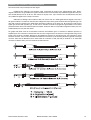
APÉNDICE B. Conexiones de línea : no-balanceadas y balanceadas
Existen dos métodos básicos para transportar la señal de audio:
Línea no-balanceada: Emplea un cable con dos conductores, transportando la señal como diferencia de potencial (voltaje) entre
ambos. El ruido electromagnético (interferencias) del entorno puede sumarse a la señal que los cables transportan, apareciendo
a la salida de nuestro sistema como ruido indeseado. Los conectores que llevan señal no-balanceada poseen dos pines, tales
como el RCA (Phono), y el 1/4” (6.35 mm, comúnmente llamado jack) mono.
Línea balanceada: Emplea un cable con tres conductores. Uno de ellos sirve de pantalla contra el ruido electromagnético y es el
cable de tierra. Los otros dos tienen la misma tensión respecto del cable de tierra pero con signos opuestos. El ruido que no
pueda ser rechazado por el blindaje afecta por igual a los dos cables que transportan la señal. La mayor parte de los aparatos
electrónicos de audio profesional trabajan con entrada balanceada. En estos aparatos el circuito de entrada toma la diferencia
de potencial entre los dos cables que transportan la señal con voltajes opuestos, rechazando por tanto el ruido, que tiene el
mismo signo en ambos cables. Los conectores que pueden llevar señal balanceada poseen tres pines, tales como el XLR
(Cannon), y el 1/4” (jack) estéreo.
Todas las entradas y salidas de señal de la unidad son balanceadas. Ello permite aprovecharse de la ventajas de las conexiones
balanceadas pero manteniendo la compatibilidad con las no-balanceadas.
Los gráficos que siguen muestran la conexión recomendada desde diferentes tipos de conectores: los conectores de la
izquierda vienen de la fuente de sonido y los de la derecha van a las entradas de la unidad. Observe que en los conectores no
balanceados de la izquierda unimos dos terminales dentro del conector. En las conexiones de salida balanceada a entrada
balanceada, en caso de aparecer zumbidos, pruebe a desconectar la malla o tierra (sleeve, ground) en el conector de entrada a
la unidad. Nótese que los gráficos indican qué pin se tiene que conectar con qué otro pin, pero que las posiciones de los pines
son diferentes a las de un conector XLR en la realidad. También se asume que los dispositivos usan el pin 2 en el XLR como
positivo.
Serie PowerPro/ PowerPro series
Manual del usuario / User's manual
7
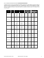
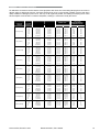
APÉNDICE C. Tablas para la selección del cable
La pérdida de potencia y el factor de amortiguamiento resultante se muestran para varias longitudes y secciones de cable. Se
recomienda un factor de amortiguamiento mínimo de 25, y preferiblemente no inferior a 50 para instalaciones de calidad.
Aunque, por ejemplo una pérdida del 10% de la potencia apenas sea audible, el bajo factor de amortiguamiento resultante
supone que el amplificador tiene poco control sobre el altavoz, que conlleva un sonido poco claro y con coloración en las
frecuencias graves.
LONGITUD /
LENGTH
CALIBRE
AWG (Nr.)
AREA
R (ohm)
2
PÉRDIDA DE POTENCIA /
POWER LOSS
FACTOR DE
AMORTIGUAMIENTO /
DAMPING FACTOR
8 ohm
4 ohm
8 ohm
4 ohm
18
16
14
12
10
8
0,8 mm
1,31 mm2
2,1 mm2
3,3 mm2
5,3 mm2
8,35 mm2
0.103
0.066
0.041
0.026
0.016
0.010
1,3 %
0,8 %
0,5 %
0,3 %
0,2 %
0,1 %
2,6 %
1,7 %
1,0 %
0,7 %
0,4 %
0,3 %
61
85
115
147
179
207
30
42
57
73
90
104
5 m (16.4 ft)
18
16
14
12
10
8
0,8 mm2
1,31 mm2
2,1 mm2
3,3 mm2
5,3 mm2
8,35 mm2
0.207
0.131
0.082
0.052
0.033
0.021
2,5 %
1,6 %
1,0 %
0,7 %
0,4 %
0,3 %
5,0 %
3,3 %
2,1 %
1,3 %
0,8 %
0,5 %
34
50
72
99
130
161
17
25
36
50
65
81
7,5 m (24.6 ft)
18
16
14
12
10
8
0,8 mm2
1,31 mm2
2,1 mm2
3,3 mm2
5,3 mm2
8,35 mm2
0.310
0.197
0.123
0.079
0.049
0.031
3,9 %
2,5 %
1,5 %
1,0 %
0,6 %
0,4 %
7,8 %
4,9 %
3,1 %
2,0 %
1,2 %
0,8 %
24
35
53
74
103
134
12
18
26
37
52
67
10 m (33 ft)
18
16
14
12
10
8
0,8 mm2
1,31 mm2
2,1 mm2
3,3 mm2
5,3 mm2
8,35 mm2
0.413
0.262
0.164
0.105
0.066
0.041
5,1 %
3,3 %
2,1 %
1,3 %
0,8 %
0,5 %
10,2 %
6,6 %
4,1 %
2,6 %
1,6 %
1,0 %
18
28
42
60
85
115
9
14
21
30
42
57
15 m (49 ft)
18
16
14
12
10
8
0,8 mm2
1,31 mm2
2,1 mm2
3,3 mm2
5,3 mm2
8,35 mm2
0.620
0.393
0.246
0.157
0.098
0.062
7,8 %
4,9 %
3,1 %
2,0 %
1,2 %
0,8 %
15,6 %
9,8 %
6,2 %
3,9 %
2,5 %
1,6 %
12
19
29
43
63
88
6
9
15
22
31
44
20 m (66 ft)
18
16
14
12
10
8
0,8 mm2
1,31 mm2
2,1 mm2
3,3 mm2
5,3 mm2
8,35 mm2
0.827
0.525
0.328
0.210
0.131
0.082
10,3 %
6,5 %
4,1 %
2,6 %
1,6 %
1,0 %
20,6 %
13,1 %
8,2 %
5,3 %
3,3 %
2,0 %
9
14
22
34
50
72
5
7
11
17
25
36
50 m (164 ft)
16
14
12
10
8
6
1.31 mm2
2.1 mm2
3.3 mm2
5.3 mm2
8.35 mm2
13.3 mm2
1.313
0.820
0.525
0.328
0.205
0.125
16.4 %
7.7 %
4.9 %
3.1 %
1.9 %
1.6 %
32.8 %
15.4 %
9.8 %
6.1 %
3.9 %
3.1 %
6
12
19
29
44
52
3
6
10
15
22
26
75 m (246 ft)
14
12
10
8
6
2.1 mm2
3.3 mm2
5.3 mm2
8.35 mm2
13.3 mm2
1.230
0.788
0.491
0.308
0.186
15.4 %
9.9 %
6.1 %
3.9 %
2.3 %
30.8 %
19.7 %
12.3 %
7.7 %
4.7 %
6
9
15
24
37
3
5
8
12
19
100 m (328 ft)
12
10
8
6
3.3 mm2
5.3 mm2
8.35 mm2
13.3 mm2
1.050
0.655
0.410
0.248
13.1 %
8.2 %
5.1 %
3.1 %
26.3 %
16.4 %
10.2 %
6.2 %
7
12
18
29
4
6
9
14
2,5 m (8.2 ft)
Serie PowerPro/ PowerPro series
Manual del usuario / User's manual
8
INTRODUCTION
C) INPUT LEVEL CONTROLS
General
Volume levels for each channel can be adjusted by using
the knobs found on the front panel. Gain is maximum when
the LEVEL rotary potentiometer is rotated fully clockwise.
Thank you for purchasing a D.A.S. power amplifier. It has
been built with the most advanced modular technology, and
has been designed through the use of computer-aided
design for both the electronic and mechanical parts.
D) CLIP LED
In the event that the signal’s excursion exceeds the
maximum voltage from the power supply, the unit will
indicate saturation through the clip LED of the channel
involved. An automatic limiting system will impede
prolonged saturation.
Features
•
•
•
•
•
•
•
•
•
•
•
•
•
Class AB
Linear Switching Power
Dual balanced XLR inputs
Binding post and Speakon output connections (PS-800
and PS-1400 only)
Variable speed back-to-front fan cooling
Front located volume controls
Input Sensitivity switchable between 0.775V, 1V and
1.44V.
Ground loop selector.
Stereo, parallel and mono operation modes
Complete and independent protections on each
channel against output short-circuits, overloading and
overheating
The power supply is protected against short-circuits,
voltage and current overloading; triggering the latter to
the standby mode
Clip limiters
Clip, protection and idle LED indicators
E) PROTECTION LED
When a channel's output is disconnected by the amplifier's
protection, this yellow LED is on.
A channel’s protection may be triggered by:
•
Overheating sensed at any part of a channel. When the
amplifier has cooled down, the channel’s output will
be connected and operation will resume. The control
circuit has some degree of built-in hysterisis to avoid
turn-on and off oscillations.
•
Presence of DC at a channel’s output. Since it may
severely damage speakers, the amplifier will
deactivate the output in the event that DC levels are
too high. Once DC is no longer present, the
PROTECTION LED will turn off and output is
reactivated.
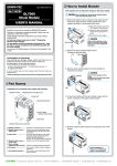
FRONT PANEL DESCRIPTION
PS-200, PS-400
Level A
Clip
ELECTRONICS
Protection
PS-400
On
On
D
Level B
Protection
Signal
Signal
G
Clip
C F B
PowerPro Series
A E
PS-800, PS-1400
®
ELECTRONICS
PS-800
Clip
Clip
Protection
Protection
Signal
Signal
On
Level A
On
Level B
PowerPro Series
G
D
C
F B
A) POWER SWITCH
Turns the amplifier on ("|" position") , and turns the
amplifier off ("0" position).
B) POWER LED
When these green LEDs illuminate, it indicates that
both amplifier channels are ready.
Serie PowerPro/ PowerPro series
A
E
•
Short-circuit at a channel’s output (only PS-200 and
PS-400) or load impedance is too low this protection
is activated. In this case, once the short circuit is
gone the output is NOT reactivated; the amplifier
needs to be switched off and on to reactivate.
•
When the amplifier is switched on, the output is also
deactivated for a few seconds to prevent dangerous
transients from damaging the speakers, and the
PROTECTION LED is on until the amplifier is ready for
use.
Manual del usuario / User's manual
9
F) SIGNAL LED
These green LEDs show the presence of signal at the
amplifier's inputs, and is dependent on the position of the
LEVEL control.
C) INPUT MODE
This switch allows the selection of the input configuration
mode: stereo, parallel or bridge.
Typically the amplifiers are used in stereo mode, where the
input to channel A feeds channel A and the input to channel
B feeds channel B.
G) COOLING AIR OUTLET GRILLES
Fan cooling permits airflow through the most vital parts of
the amplifier. Since the airflow finds its way out through
these grilles, keep them as clean and dust-free as possible
to assure proper cooling.
Parallel mode allows feeding both channels with the signal
plugged into channel A. Channel B's input isn’t
disconnected in this mode, therefore it can be used as a
link thru connection.
REAR PANEL DESCRIPTION
PS-200, PS-400
F 5A L 250V FUSE
HOT
COLD
CH B INPUT
GND
HOT
COLD
STEREO
CH A INPUT
FOR CONTINUED PROTECTION AGAINST RISK OF FIRE, REPLACE ONLY WITH THE SAME FUSE TYPE
F
SPEAKER OUTPUT
SENSITIVITY GROUND S.N.
1.44V
OFF
MODEL: PS-400
230V
50/60Hz 5A
OUTPUT PWR PER CH: 200W@4
D.A.S. AUDIO S.A. , SPAIN
MADE IN CHINA
0.775V
ON
2
BRIDGE
CH A
1.0V
PARALLEL
BRIDGE
C
3
GND
N1918
1
D E
B
CH B
G
A
S.N.
GROUND
CH B INPUT
CH B
PS-800, PS-1400
OFF
MODEL: PS-800
230V
10A 50Hz/60Hz
OUTPUT PWR PER CH: 390W@4
ON
N1918
FOR CONTINUED PROTECTION AGAINST RISK
OF FIRE REPLACE ONLY WITH THE SAME TYPE
F 10A L 250V FUSE
GND
3
2
HOT
1
COLD
GND
SENSITIVITY
CH A INPUT
SPEAKER OUTPUT
1.0V
0.775V
1.44V
CAUTION
RISK OF ELECTRIC SHOCK
DO NOT OPEN
ATTENTION
DANGER D’ELECTROCUTION
NE PAS OUVRIR
WARNING: TO REDUCE RISK OF FIRE OR ELECTRIC SHOCK
DO NOT EXPOSE THIS EQUIPMENT TO RAIN OR MOISTURE
D.A.S. AUDIO S.A. (VALENCIA) SPAIN
MADE IN CHINA
F
1+ 1-
VER MANUAL DE INSTRUCCIONES PARA LA CONEXIÓN
REFER TO INSTRUCTIONS MANUAL FOR CONNECTION
ANSCHLUSSWEISE BITTE DER ANLEITUNG ENTNEHMEN
VOIR MANUEL D'INSTRUCTIONS POUR LA CONNEXION
B
E
D
C
CH A
1+ 1CH B
2+ 2BRIDGE 1+ 2+
CH A
HOT
COLD
CH B
PARALLEL
BRIDGE
MODE STEREO
BRIDGE
A
G
A) OUTPUT CONNECTIONS
Channel output connections to speakers is by binding
posts. PS-800 and PS-1400 models also provide Speakon
NL4 connections.
For the binding posts, polarity is clearly indicated by black
(–) and red (+) output terminals.
For the lower Speakon connector, pin assignments are:
Channel A : +1 / -1
Channel B : +2 / -2
Bridge : +1 / +2
For the Speakon situated on top, pin assignments are:
Channel B : +1 / -1
B) INPUTS
XLR and Jack inputs are connected in parallel.
Nominal input impedance is 20k ohm for balanced use and
10k ohm for unbalanced use.
Polarity complies with AES14-1992 (ANSI S4.48-1992) and
therefore pin assignments are:
1 or (Jack sleeve) = GND (Ground)
2 or (Jack Tip) = (+) non-inverted signal
3 or (Jack ring) = (–) inverted signal
Serie PowerPro/ PowerPro series
Bridge mode sums both amplifier channels together, thus
doubling the output power. Refer to the “Bridge Mode
Operation” Appendix for further information.
D) INPUT SENSITIVITY SELECTOR
This selector allows to choose the input sensitivity 0.775V,
1.00V and 1.44V.
E) GROUND LOOP SELECTOR
The selector is used to avoid ground loops. Set the selector
in the “OFF” position when loops are detected.
F) MAINS LEAD
The mains lead is a connector type IEC320 terminated on a
plug.
If you need to cut off the plug to replace it for the type used
in your region, cable colour codes are brown (live), blue
(neutral) and yellow-green (earth). The appropriate fuse is
provided in the connector.
G) FAN INLET GRILLES
Like for the front outlet grilles, keep clean and dust-free to
assure free air intake for proper cooling.
Manual del usuario / User's manual
10
INSTALLATION
Power consumption
Racking
Can be seen on the accompanying table for 230V. Double
the ratings to get the 115V current consumption.
All amplifiers are 19-inch rack mount width. PS-200 and
PS-400 are 1U DIN in height. PS-800 and PS-1400 400 are
2U DIN in height.
International safety agencies specify AC consumption using
pink noise at 1/8th of maximum power. This is done to
represent the current requirements to reproduce a typical
musical programme. The 1/3rd power rating represents a
worst case scenario, while the maximum power represents
consumption with sine wave signal, which will never occur
in practice.
Four front-panel mounting holes are provided for use with
M5 or M6 or 1/4” screws. To avoid bending the chassis in
rack mounting applications where the rack will be
transported, mount the amplifiers to the back of the rack
using the rear mounting holes. Alternatively, place the
bottom amplifier against the base of
Consumos eléctricos / Power consumption (Amperios / Amperes)
the rack and pile the amplifiers with
Potencia / Power
Max
1/3
1/8
no clearance in between.
Amplifiers’ dimensions can be found
on the “Line Drawings” section of this
manual.
PS-200
8+8 ohm
4+4 ohm
Puente/bridge 8 ohm
0.87
1.57
1.6
0.31
0.57
0.6
0.15
0.25
0.25
Sin señal
idle
0.05
0.05
0.05
PS-400
8+8 ohm
4+4 ohm
Puente/bridge 8 ohm
1.64
2.98
3.0
0.57
1.06
1.1
0.27
0.47
0.5
0.08
0.08
0.08
PS-800
8+8 ohm
4+4 ohm
Puente/bridge 8 ohm
2.8
5.28
5.3
0.98
1.82
1.85
0.48
0.81
0.85
0.15
0.15
0.15
5.2
9.59
9.6
1.82
3.41
3.45
0.84
1.48
1.5
0.2
0.2
0.2
Cooling
A fan cools the aluminium heat sinks
and transformer from back to front.
When mounting the unit onto a 19PS-1400 8+8 ohm
inch rack, a rack cooling system is
4+4 ohm
Puente/bridge
not required, since the air is
exhausted out through the front grille.
However, the rack must not be sealed, and it should at
least have a large enough ventilation grille to allow air into
the rack.
8 ohm
Input cable connections
The Input Cabling Appendix shows balanced and
unbalanced connection from different types of connector to
the amplifiers.
Speaker cable connections
Either the binding posts or the Speakon connectors (PS800,PS-1400) can be used.
The binding posts can be used with bare wire or banana
connectors. In either case, ensure that you remove the
required length of cable sleeve that allows for the conductor
itself to be hidden. Always note polarity (red=+,black=–).
Speakon connectors offer quick connection for portable
applications. To enable a Speakon connection, plug the
male connector into the outlet and rotate it clockwise. It
will then lock into place and be ready for use.
The Appendices of this manual include a table to aid in the
selection of the appropriate cable gauge.
Connection to mains
Nominal AC voltage will always be indicated on the back
panel. 230V and 115V versions are available. Be sure your
unit has the nominal AC voltage for your country.
Serie PowerPro/ PowerPro series
Manual del usuario / User's manual
11
USE
WARRANTY
SWITCH ON/OFF
All D.A.S. products are warrantied against any
manufacturing defect for a period of 2 years.
The warranty excludes damage from incorrect or
misuse use of the product.
All warranty repairs must be exclusively undertaken by the
factory or any of its authorised service centers.
To claim a warranty repair, do not open or intend to repair
the product. Return the damaged unit, risk-free and freight
pre-paid, to the nearest service center with a copy of the
purchase invoice.
The main power switch turns the amplifier on.
When the power switch is turned On ("|" position) the
PROTECTION LED illuminates. After approximately 7
seconds the main power supply voltage will be turned on
internally and the ON LEDs will illuminate. Then the
PROTECTION LED will go out and the amplifier will be ready
to be used.
To turn the amplifier off push the power switch ("0"
position). At that moment the main power supply voltage
and the secondary power supply voltage will turn off
internally.
Switch your sound system on from back to front. Thus,
switch on the amplifiers last on your sound system. Switch
sound sources (CDs, turntables) first, then your mixer, then
your processors and crossovers and finally the amplifiers. If
you have more than one amplifier, switch them on
sequentially, one at a time or use a sequencer.
Follow the reverse order when switching off, and switch off
the amplifiers before any other element on your sound
system.
CLIP LED
The clip LED should never be on continuously. This will
distort the signal and may damage the speakers. In fact,
severe clipping is an easy way of burning a speaker’s voice
coil.
The amplifiers feature an automatic limiting system that
impedes prolonged saturation, but the dynamic nature of
music signals stops it from being a brick wall protection.
Thus at most, the clip light could be lit occasionally.
LEVEL CONTROLS
The LEVEL rotary potentiometer is used for changing the
input gain. Although related to output power, it is not a
direct representation of it. Thus, we can have maximum
output power with the gain at mid position. Similarly, we
may have the gain controls at maximum and not have
maximum output if our source signal is not strong enough.
One way to use the volume controls is to set them such
that when the mixer’s faders are at their maximum level,
we are just below clipping level on the amplifier or clipping
very occasionally.
Serie PowerPro/ PowerPro series
Manual del usuario / User's manual
12
SPECIFICATIONS
PS-200
PS-400
PS-800
PS-1400
70 W
100 W
200 W
140 W
200 W
400 W
250 W
400 W
800 W
450 W
700 W
1400W
Potencia EIA ambos canales / EIA Power, both
channels driven (1 kHz @ 1% THD)
8 ohm, estéreo / stereo
4 ohm, estéreo / stereo
8 ohm, puente / bridge
Distorsion (típica) / Distortion (typical) (20-20k Hz)
Distorsión de Intermodulación / Intermodulation
Distortion
Velocidad de Salto / Rise Time
Respuesta en frecuencia / Frequency Response
Factor de amortiguamiento / Damping Factor (8 Ω)
Relación Señal-Ruido / Signal to Noise (20 Hz-20 kHz)
Crosstalk
Impedancia de entrada / Input Impedance
Topología / Topology
Peso / Weight
Dimensiones / Dimensions
<0.5%
<0.5%
25 V/us
20Hz – 20kHz +1/-1dB
>100
>90dB
>60dB
10K Ohm no bal./unbal., 20K Ohm bal.
Clase AB / Class AB
12 kg (26.4 lb) 13 kg (28.6 lb) 18 kg ( 39.6 lb) 21 kg ( 46lb)
Véase sección Dibujos de línea / See Line Drawings section
LINE DRAWINGS
PS-200, PS-400:
44mm [7/4”]
PS-400
Clip
HOT
Level B
Protection
Signal
On
On
CH B INPUT
BRIDGE
COLD
HOT
COLD
FOR CONTINUED PROTECTION AGAINST RISK OF FIRE, REPLACE ONLY WITH THE SAME FUSE TYPE
482.6mm [19”]
SPEAKER OUTPUT
SENSITIVITY GROUND S.N.
1.44V
OFF
MODEL: PS-400
230V
50/60Hz 5A
OUTPUT PWR PER CH: 200W@4
D.A.S. AUDIO S.A. , SPAIN
MADE IN CHINA
0.775V
ON
GND
STEREO
CH A INPUT
PowerPro Series
BRIDGE
CH A
1.0V
ELECTRONICS
Signal
PARALLEL
Protection
F 5A L 250V FUSE
Clip
Level A
33mm [5/4”]
348mm [13 2/3”]
3
GND
CH B
2
N1918
1
464mm [18 1/4”]
RISK OF ELECTRIC SHOCK
DO NOT OPEN
DANGER D’ELECTROCUTION
NE PAS OUVRIR
ATTENTION
386mm [15 1/5”]
CAUTION
PS-800
Signal
On
CH B INPUT
S.N.
GROUND
OFF
ON
N1918
Clip
HOT
COLD
Signal
On
MODEL: PS-800
230V
10A 50Hz/60Hz
OUTPUT PWR PER CH: 390W@4
FOR CONTINUED PROTECTION AGAINST RISK
OF FIRE REPLACE ONLY WITH THE SAME TYPE
F 10A L 250V FUSE
MODE STEREO
Protection
GND
BRIDGE
3
2
1
HOT
PARALLEL
GND
Level B
SENSITIVITY
1.44V
CAUTION
ATTENTION
DANGER D’ELECTROCUTION
NE PAS OUVRIR
WARNING: TO REDUCE RISK OF FIRE OR ELECTRIC SHOCK
DO NOT EXPOSE THIS EQUIPMENT TO RAIN OR MOISTURE
D.A.S. AUDIO S.A. (VALENCIA) SPAIN
MADE IN CHINA
VER MANUAL DE INSTRUCCIONES PARA LA CONEXIÓN
REFER TO INSTRUCTIONS MANUAL FOR CONNECTION
ANSCHLUSSWEISE BITTE DER ANLEITUNG ENTNEHMEN
VOIR MANUEL D'INSTRUCTIONS POUR LA CONNEXION
CH A
1+ 1CH B
2+ 2BRIDGE 1+ 2+
464mm [18 1/4”]
386mm [15 1/5”]
373mm [14 2/3”]
1+ 1-
SPEAKER OUTPUT
1.0V
0.775V
RISK OF ELECTRIC SHOCK
DO NOT OPEN
PowerPro Series
482.6mm [19”]
CH B
COLD
CH A INPUT
BRIDGE
Clip
Protection
Level A
76.2mm [3”]
CH A
®
ELECTRONICS
88mm [3 ½”]
CH B
PS-800, PS-1400:
Serie PowerPro/ PowerPro series
Manual del usuario / User's manual
13
APPENDIX A. Bridge Mode Operation
To operate in bridge mode, follow these steps:
1.Switch off the amplifier.
2.Turn volume control potentiometers on the front panel to minimum position (fully anticlockwise).
3.Connect input signal to channel A.
4.Set mode switch to “BRIDGE”.
5.Connect speakers as follows:
Connect (+) to red speaker terminal on channel A’s output terminals
Connect (-) to red speaker terminal on channel B’s output terminals
6. Turn volume control potentiometers on the front panel to maximum position (fully clockwise).
7. Control volume levels from the mixer or pre-amp only.
NOTE: We do not recommend using bridge mode with loads lower than 4 ohms
Serie PowerPro/ PowerPro series
Manual del usuario / User's manual
14
APPENDIX B. Line connections : unbalanced and balanced
There are two basic ways to transport an audio signal:
Unbalanced line: Utilising a two-conductor cable, it transports the signal as the voltage between them. Electromagnetic interference can get added to the signal as undesired noise. Connectors that carry unbalanced signals have two pins,
such as RCA (Phono) and 1/4” (6.35 mm, often referred to as jack) mono. 3-pin connector such as XLR (Cannon) may also
carry unbalanced signals if one of the pins is unused.
Balanced line: Utilising a three-conductor cable, one of them acts as a shield against electro-magnetic noise and is
the ground conductor. The other two have the same voltage with respect to the ground conductor but with opposite signs. The
noise that cannot be rejected by the shield affects both signal conductors in the same way. At the device’s input the two
signals get summed with opposite sign, so that noise is cancelled out while the programme signal doubles in level. Most
professional audio devices use balanced inputs and outputs. Connectors that can carry balanced signal have three pins, such
as XLR (Cannon) and 1/4” (6.35 mm) stereo.
The graphs that follow show the recommended connection with different types of connectors to balanced processor or
amplifier inputs. The connectors on the left-hand side come from a signal source, and the ones on the right hand side go to the
inputs of the processor or amplifier. Note that on the unbalanced connectors on the left-hand side, two terminals are joined
inside the connector. If hum occurs with balanced to balanced connections, try disconnecting the sleeve (ground) on the input
connector. Note that the illustrations show what should be connected to what, but that pin locations on an actual XLR
connector are different. Also, pin 2 hot is assumed on XLR connectors.
Serie PowerPro/ PowerPro series
Manual del usuario / User's manual
15
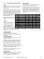
APPENDIX C. Tables for cable selection
The table below is intended to aid the selection of the appropriate cable. Power loss and resulting damping factor are shown for
different values of cable length and area. A minimum damping factor of 25 is recommended, preferably not lower than 50 for
quality installations. Although a power loss of 10% may not be significantly audible, the resulting low damping factor means
that the amplifier will not be able to control the loudspeaker, resulting in a coloured and muddy bass sound.
LONGITUD /
LENGTH
CALIBRE
AWG (Nr.)
AREA
R (ohm)
2
PÉRDIDA DE POTENCIA /
POWER LOSS
FACTOR DE
AMORTIGUAMIENTO /
DAMPING FACTOR
8 ohm
4 ohm
8 ohm
4 ohm
18
16
14
12
10
8
0,8 mm
1,31 mm2
2,1 mm2
3,3 mm2
5,3 mm2
8,35 mm2
0.103
0.066
0.041
0.026
0.016
0.010
1,3 %
0,8 %
0,5 %
0,3 %
0,2 %
0,1 %
2,6 %
1,7 %
1,0 %
0,7 %
0,4 %
0,3 %
61
85
115
147
179
207
30
42
57
73
90
104
5 m (16.4 ft)
18
16
14
12
10
8
0,8 mm2
1,31 mm2
2,1 mm2
3,3 mm2
5,3 mm2
8,35 mm2
0.207
0.131
0.082
0.052
0.033
0.021
2,5 %
1,6 %
1,0 %
0,7 %
0,4 %
0,3 %
5,0 %
3,3 %
2,1 %
1,3 %
0,8 %
0,5 %
34
50
72
99
130
161
17
25
36
50
65
81
7,5 m (24.6 ft)
18
16
14
12
10
8
0,8 mm2
1,31 mm2
2,1 mm2
3,3 mm2
5,3 mm2
8,35 mm2
0.310
0.197
0.123
0.079
0.049
0.031
3,9 %
2,5 %
1,5 %
1,0 %
0,6 %
0,4 %
7,8 %
4,9 %
3,1 %
2,0 %
1,2 %
0,8 %
24
35
53
74
103
134
12
18
26
37
52
67
10 m (33 ft)
18
16
14
12
10
8
0,8 mm2
1,31 mm2
2,1 mm2
3,3 mm2
5,3 mm2
8,35 mm2
0.413
0.262
0.164
0.105
0.066
0.041
5,1 %
3,3 %
2,1 %
1,3 %
0,8 %
0,5 %
10,2 %
6,6 %
4,1 %
2,6 %
1,6 %
1,0 %
18
28
42
60
85
115
9
14
21
30
42
57
15 m (49 ft)
18
16
14
12
10
8
0,8 mm2
1,31 mm2
2,1 mm2
3,3 mm2
5,3 mm2
8,35 mm2
0.620
0.393
0.246
0.157
0.098
0.062
7,8 %
4,9 %
3,1 %
2,0 %
1,2 %
0,8 %
15,6 %
9,8 %
6,2 %
3,9 %
2,5 %
1,6 %
12
19
29
43
63
88
6
9
15
22
31
44
20 m (66 ft)
18
16
14
12
10
8
0,8 mm2
1,31 mm2
2,1 mm2
3,3 mm2
5,3 mm2
8,35 mm2
0.827
0.525
0.328
0.210
0.131
0.082
10,3 %
6,5 %
4,1 %
2,6 %
1,6 %
1,0 %
20,6 %
13,1 %
8,2 %
5,3 %
3,3 %
2,0 %
9
14
22
34
50
72
5
7
11
17
25
36
50 m (164 ft)
16
14
12
10
8
6
1.31 mm2
2.1 mm2
3.3 mm2
5.3 mm2
8.35 mm2
13.3 mm2
1.313
0.820
0.525
0.328
0.205
0.125
16.4 %
7.7 %
4.9 %
3.1 %
1.9 %
1.6 %
32.8 %
15.4 %
9.8 %
6.1 %
3.9 %
3.1 %
6
12
19
29
44
52
3
6
10
15
22
26
75 m (246 ft)
14
12
10
8
6
2.1 mm2
3.3 mm2
5.3 mm2
8.35 mm2
13.3 mm2
1.230
0.788
0.491
0.308
0.186
15.4 %
9.9 %
6.1 %
3.9 %
2.3 %
30.8 %
19.7 %
12.3 %
7.7 %
4.7 %
6
9
15
24
37
3
5
8
12
19
100 m (328 ft)
12
10
8
6
3.3 mm2
5.3 mm2
8.35 mm2
13.3 mm2
1.050
0.655
0.410
0.248
13.1 %
8.2 %
5.1 %
3.1 %
26.3 %
16.4 %
10.2 %
6.2 %
7
12
18
29
4
6
9
14
2,5 m (8.2 ft)
Serie PowerPro/ PowerPro series
Manual del usuario / User's manual
16
NOTAS / NOTES
Serie PowerPro/ PowerPro series
Manual del usuario / User's manual
17
US/PS-00
D.A.S. AUDIO S.A.
C/. Islas Baleares, 24
46988 Fuente del Jarro - Valencia, SPAIN
Tel. 96 134 0525 - Tel. Intl. +34 96 134 0860
Fax. 96 134 0607 - Fax. Intl. +34 96 134 0607
D.A.S. Audio of America, Inc.
Sunset Palmetto Park 6816 NW 77th Court. Miami, FL.
33166 - U.S.A. Tel. 305 436 0521 - Fax. 305 436 0528
http://www.dasaudio.com