1
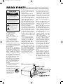
AVA 7 OM (New)
6/20/05
3:50 PM
Page 1
JBL PERFORMANCE™ SERIES
OWNER’S GUIDE
AVA7
HIGH-PERFORMANCE
7-CHANNEL
POWER AMPLIFIER
AVA 7 OM (New)
6/20/05
3:50 PM
Page 2
AVA7 POWER AMPLIFIER
3
Important Safety Precautions
4
Introduction and Features
5
Operation and Controls
7
Connecting Your JBL Performance Series System
9
Installing the AVA7
10
Troubleshooting
11
AVA7 Specifications
®
AVA 7 OM (New)
6/20/05
3:50 PM
Page 3
READ FIRST! IMPORTANT SAFETY PRECAUTIONS!
CAUTION
RISK OF ELECTRIC SHOCK
DO NOT OPEN
CAUTION: To reduce the risk of electric shock,
do not remove cover (or back).
No user-serviceable parts inside.
Refer servicing to qualified service personnel.
CAUTION: To prevent electric shock,
do not use this (polarized) plug with
an extension cord, receptacle or other outlet
unless the blades can be fully inserted to
prevent blade exposure.
The lightning flash with arrowhead symbol,
within an equilateral triangle, is intended to
alert the user to the presence of uninsulated
“dangerous voltage” within the product’s
enclosure that may be of sufficient magnitude to constitute
a risk of electric shock to persons.
The exclamation point within an equilateral
triangle is intended to alert the user to the
presence of important operating and
maintenance (servicing) instructions in the
literature accompanying the appliance.
1. Read these instructions.
2. Keep these instructions.
3. Heed all warnings.
4. Follow all instructions.
5. Do not use this apparatus near
water.
6. Clean only with a dry cloth.
7. Do not block any ventilation
openings. Install in accordance
with the manufacturer’s instructions.
8. Do not install near any heat sources
such as radiators, heat registers, stoves
or other apparatus (including amplifiers)
that produce heat.
9. Do not defeat the safety purpose of
the polarized or grounding-type plug. A
polarized plug has two blades with one
wider than the other. A grounding-type
plug has two blades and a third grounding prong. The wide blade or the third
prong is provided for your safety. If the
provided plug does not fit into your outlet, consult an electrician for replacement of the obsolete outlet.
10. Protect the power cord from being
walked on or pinched, particularly at
plugs, convenience receptacles and
the point where they exit from the
apparatus.
11. Only use attachments/accessories
specified by the manufacturer.
12. Use only with the cart, stand,
tripod, bracket or table specified by the
manufacturer or sold with the apparatus. When a cart is used,
use caution when moving the cart/apparatus
combination to avoid
injury from tip-over.
13. Unplug this apparatus during lightning storms or when unused for long
periods of time.
14. Refer all servicing to qualified
service personnel. Servicing is required
when the apparatus has been damaged
in any way, such as power-supply cord
or plug is damaged, liquid has been
spilled or objects have fallen into the
apparatus, the apparatus has been
exposed to rain or moisture, does not
operate normally, or has been dropped.
15. Do not use attachments not recommended by the product manufacturer,
as they may cause hazards.
16. This product should be operated
only from the type of power source indicated on the marking label. If you are
not sure of the type of power supply to
your home, consult your product dealer
or local power company. For products
intended to operate from battery power,
or other sources, refer to the operating
instructions.
17. If an outside antenna or cable
system is connected to the product,
be sure the antenna or cable system
is grounded so as to provide some
protection against voltage surges
and built-up static charges. Article
810 of the National Electrical Code,
ANSI/NFPA 70, provides information
with regard to proper grounding of the
mast and supporting structure, grounding of the lead-in wire to an antenna
discharge unit, size of grounding conductors, location of antenna-discharge
unit, connection to grounding electrodes, and requirements for the
grounding electrode. See Figure A.
18. An outside antenna system should
not be located in the vicinity of overhead power lines or other electric light
or power circuits, or where it can fall
into such power lines or circuits. When
installing an outside antenna system,
extreme care should be taken to keep
from touching such power lines or circuits, as contact with them might be
fatal.
19. Do not overload wall outlets, extension cords, or integral convenience
receptacles, as this can result in a risk
of fire or electric shock.
20. Never push objects of any kind into
this product through openings, as they
may touch dangerous voltage points or
short-out parts that could result in a fire
or electric shock. Never spill liquid of
any kind on the product.
21. The apparatus shall not be exposed
to dripping or splashing, and no objects
filled with liquids, such as vases, shall
be placed on the apparatus.
22. Do not attempt to service this product yourself, as opening or removing
covers may expose you to dangerous
voltage or other hazards. Refer all servicing to qualified service personnel.
23. When replacement parts are
required, be sure the service technician
has used replacement parts specified
by the manufacturer or that have the
same characteristics as the original
part. Unauthorized substitutions may
result in fire, electric shock or other
hazards.
24. Upon completion of any service or
repairs to this product, ask the service
technician to perform safety checks to
determine that the product is in proper
operating condition.
25. The product should be mounted to a
wall or ceiling only as recommended by
the manufacturer.
Figure A.
Example of Antenna Grounding as per
National Electrical Code ANSI/NFPA 70
HCGUL1492/6500 04/2004 EN
3
AVA 7 OM (New)
6/20/05
3:50 PM
Page 4
INTRODUCTION AND FEATURES
INTRODUCTION
Congratulations on your purchase of
this JBL Performance™ Series AVA7
power amplifier! You have purchased a
product that embodies the best of what
JBL has learned about the emotional
power of audio reproduction in more
than fifty years of preeminence in the
field. This amplifier has been designed
and crafted to provide the user with
a high level of sonic performance.
Special attention has been paid to minimizing the number of components in
the audio signal path, resulting in
extremely low distortion, excellent
transient response, and wide dynamic
range. JBL products set new benchmarks in audio technology, and, when
used as part of a complete JBL
Performance Series system, will bring
the ambience and acoustics of some of
the world’s greatest concert halls and
theaters into your home.
To obtain the best performance from this
amplifier, please be sure to completely
read this user’s manual and use the
AVA7 only in accordance with its
instructions.
FEATURES
The JBL Performance Series AVA7
power amplifier features the following:
Full Seven-Channel Operation
The AVA7 has been designed to integrate well into the world of multichannel audio. It is designed to reproduce
the latest development in home theater
audio – rear channels, in addition to
side channels – to produce a truly
enveloping sound field. When coupled
with a high-quality subwoofer amplifier,
it is a solid foundation on which to
build a high-performance home cinema
system that will astound the listener
with its power and realism.
High Power Capability
The AVA7 provides a satisfying 125
watts per channel of distortion-free
audio (<0.01% THD) into 8 ohms.
Because of their power capabilities,
JBL Performance Series amplifiers have
an extremely wide dynamic range, an
element critical to realistic home cinema.
Sound levels equal to those at original
performances are easily re-created in
even the largest of home listening
environments.
4
Auto Turn-On and Power-Sequencing
Circuitry
When used in a JBL Performance
System, the AVA7 can be turned on
automatically whenever the surround
processor is activated. No longer do
you have to get out of that chair to turn
on the various pieces of equipment in
your entertainment system; just one
touch on the remote control of the surround processor, and you’re a few seconds away from a truly impressive
audio presentation!
Modern amplifiers produce more
power per channel (and frequently
have more channels) than those of the
traditional two-channel stereo era. Due
to the high current demands of power
amplifiers at the instant of turn-on,
the AVA7 amplifier is equipped with
a power-sequencing circuit that
turns on each amplifier in a delayed
sequence, avoiding the large instantaneous current demand (and possible
circuit breaker tripping) that may occur
should more than one amplifier turn on
at the same instant.
Quiet Cooling
The AVA7 utilizes two fans to cool the
amplifier channels, ensuring long-term
reliability. To reduce fan noise to an
absolute minimum, a thermal-sensing
and control circuit, which senses
increases in temperature within the
amplifier and powers the fans at a
speed proportional to that temperature
increase, has been incorporated in the
JBL Performance Series AVA7. As a
result, the fan is never turning faster
than necessary, and most of the noise
that is generated is masked by the program being listened to.
Comprehensive and Isolated Circuit
Protection
The AVA7 amplifier employs sophisticated protection circuitry (one for each
channel) that senses many possible fault
conditions, such as shorted loudspeaker
wires or excess power demand, and
turns the affected channel(s) off until
the fault condition is removed, at which
time normal operation is automatically
restored. While protection of this sort is
not uncommon in today’s well-designed
amplifiers, a remarkable feature of the
JBL Performance AVA7’s protection circuits is that they are optically coupled
to the signal circuit; there is no direct
electrical connection between the signal path and the protection circuitry. As
a result, there can be no coloration of
the music, no interaction between protection and amplification, until certain
thresholds are exceeded, at which
point the channel(s) would turn off
completely.
AVA 7 OM (New)
6/20/05
3:50 PM
Page 5
OPERATION AND CONTROLS
™
¡
1. Power Switch
Pushing this button is all that is required
to turn on the AVA7 if it is not part of a
JBL Performance Series system and
the Main Switch § is in the On position. If the amplifier is used as part of a
JBL Performance Series system, the
Main Switch § and the front-panel
push button Power Switch ¡ should
both be left in the On position. The
amplifier will then turn on when the
surround processor is activated. See
the descriptions of the Main Switch §
and Trigger Jacks ¶ for more information on turning on the AVA7.
2. Standby Indicator
This indicator on the front-panel Power
Switch ¡ will glow red when the
amplifier is in the “standby” mode,
whether operating as part of a JBL
Performance Series system or not.
When the AVA7 is in the “on” mode,
this light will turn blue.
3. Input Jacks (Ch. 1 Through Ch. 7)
Seven of the output signals from the
JBL Performance Series AV1 digital
processor are connected to the seven
input jacks. We suggest the channels
be assigned as follows:
Ch. 1
Ch. 2
Ch. 3
Ch. 4
Ch. 5
Ch. 6
Ch. 7
Right Rear
Right Side
Right Front
Center
Left Front
Left Side
Left Rear
4. Speaker Terminals
Connect the speakers to these terminals, following the normal convention;
wire the “+” side of the speaker to the
red terminal, and the “–” side to the
black terminal. Wire the speakers
with the proper polarity; reversing any
speaker’s connections will not damage
either the speaker or the amplifier, but
will result in poor low-frequency performance and imprecise imaging.
WARNING: Terminals marked with the
flash symbol are hazardous when live.
External wiring connected to those terminals requires installation by trained
personnel, and the use of ready-made
lead cords.
NOTE: The minimum load impedance
that this amplifier can handle safely is 8
ohms per channel. Using lower impedance loads can damage the unit and
will void your warranty!
Wire Run Length
Up to 20' (6m)
Up to 50' (15m)
Up to 100' (30m)
Minimum Gauge
16
14
12
5. External Fuses
The AC mains fuse is located on the
back panel of the amplifier. This fuse
will not blow unless the amplifier is
asked to produce more power than its
design allows for a prolonged period or
to prevent excessive current draw that
could damage internal components
during a fault condition. The amplifier
has been designed to operate under
virtually all conditions. Even momentary
short-circuiting of the output (speaker)
connections will not ordinarily damage
the output circuitry (although this will
activate internal protection circuitry
and could cause one or more of the
channels to temporarily mute until the
circuit automatically resets).
Fuse Replacement
To remove the fuse, turn off the power
switch and disconnect the power plug
from the AC mains. Remove the fuse
holder by lifting up the latch at the
bottom and pulling the holder out.
When looking at the fuse holder as
installed on the back panel, the fuse on
the right hand side is the active fuse.
The fuse on the left is a spare. Remove
the fuse on the right side and visually
inspect it to see whether it has opened;
if it has, discard it and replace it with
the spare glass fuse. Reinstall the
holder, and reconnect the AC mains.
If after replacing the fuse the unit is
inoperative, service is required; contact
your JBL dealer.
WARNING: Always unplug the
amplifier from the AC mains
before removing any fuse.
IMPORTANT:
Never install a fuse that has a
higher rating than the one specified on
the back panel of the amplifier or in the
owner’s manual.
6. Main Switch
Place this switch in the On position at
all times during normal use.
7. Trigger Input and Output Jacks
When using the AVA7 amplifier in a JBL
Performance Series system with the
AV1 Digital Surround Processor, you
will need to use the trigger cable set
included with the AV1. Connect the DIN
end of the cable to the Trigger Output
DIN jack on the rear panel of the AV1,
and connect the 1/8" (3.5mm) plug to
the Trigger Input Jack ¶ on the rear
panel of the AVA7.
5
AVA 7 OM (New)
6/20/05
3:50 PM
Page 6
£
¶
§
∞
•
¢
If the AVA7 is used with another component (other than the AV1) that uses a
trigger for automatic turn-on and turnoff, make sure the other component’s
output is between 3 and 24 volts DC.
Connect the trigger output jack on the
other component to the 1/8" (3.5mm)
Trigger Input Jack ¶ on the AVA7
using one of the cables included with
the AVA7. Whenever a power-on trigger is used to operate the AVA7, make
sure that the AVA7’s Main Switch §
and Power Switch ¡ are both in the
On position. Since the front-panel
Power Switch ¡ on the AVA7 is a lowthrow switch, sometimes it may be difficult to confirm whether this switch
is in the On or Standby position. To
ensure that this switch is in the On
position, disconnect the trigger input
cable from the AVA7, make sure the
Main Switch § is still on, and then
press the Power Switch ¡ until its
LED Standby Indicator ™ glows blue.
Then reconnect the trigger cable to the
AVA7 Trigger Input ¶. If the Trigger
source (JBL Performance AV1 or
another source unit featuring power-on
trigger) is on, the AVA7’s LED Standby
Indicator ™ will continue to glow blue.
If the Trigger source is off or in standby,
the AVA7 will also go into standby and
its LED Standby Indicator ™ will turn
red. Once this setup is complete, the
AVA7 will automatically turn on and off
along with the source unit.
If you wish to have other components
in your system turn on via trigger, make
sure they are compatible with the 1/8"
(3.5mm) 12-volt DC Trigger Output Jack
¶ on the AVA7. If they are, you may
6
connect the Trigger Output Jack ¶ to
the first component’s trigger input using
one of the cables included with the
AVA7, and then connect all components in daisy-chain fashion. 12V DC
voltage at the AVA7 Trigger Output
Jack ¶ becomes available approximately two seconds after the AVA7
receives a 12V DC trigger input signal.
This is done to prevent high-current
draw on your home’s AC mains supply,
which could be caused by multiple
high-power audio components turning
on at the same time.
8. AC Inlet
Your AVA7 is shipped with an IEC-type
removable power cord that mates with
the AC inlet on the rear panel. To ensure
proper operation, use the supplied
power cord. This amplifier is NOT a
multivoltage unit; using a power cord
that is not compatible with a 120V, 60Hz
AC wall receptacle will void the warranty.
AVA 7 OM (New)
6/20/05
3:51 PM
Page 7
CONNECTING YOUR JBL PERFORMANCE SERIES SYSTEM
GENERAL INFORMATION
A JBL Performance Series system
installation incorporates one power
amplifier, in addition to the amplifier(s)
used to power one or more subwoofers. If your speaker complement
includes the JBL Performance Series
PS1400 powered subwoofer module,
you may use the amplifier included in
each module. If you are using a passive subwoofer, you will need to supply
a subwoofer amplifier. All seven channels on the AVA7 are to be used for
driving the left, center, right, both side,
and both rear speakers.
Use the simplified connection diagram
on page 8 to help you understand how
to connect the AVA7 amplifier to a JBL
Performance Series system. This diagram is intended to show the signal
flow through the system. For more
detail in making these connections,
please refer to the owner’s manual for
the AV1 Surround Processor.
SUGGESTED RACK-MOUNTING ORDER
Top
#1
AV1
#2
AVA7
Connect DIN and audio/video cables
between system components, as shown
on the following pages. Make sure that
on all power amplifiers the main and
standby power switches are in the On
position. Operated in this mode, all of
the components will turn on with one
touch of the power button on the surround processor’s remote control.
When connecting the source component (such as a DVD player) to the AV1
processor, choose either a coaxial or
an optical digital audio connection, but
not both. As a backup, or if analog
recordings might be desired in the
future, you may also make the left and
right analog audio connections.
In addition to the audio connections,
select one of the following video connections, but not more than one: composite video, S-video or component
video. Remember to make the corresponding video monitor output connection from the AV1 to your video display
device.
Bass Q™
7
AVA 7 OM (New)
6/20/05
3:51 PM
Page 8
WIRING DIAGRAM
AV1
AVA7
PS1400
(or other powered subwoofer)
Subwoofer Input
8
For Future Expansion
Trigger Input
AVA 7 OM (New)
6/20/05
3:51 PM
Page 9
INSTALLING THE AVA7
Installation of the AVA7 is a straightforward process.
IMPORTANT:
The amplifier must be installed
following the directions described
below. To ensure adequate performance and safety, never install the
amplifier with less free space around
the amplifier than what is specified.
Always put amplifiers on the bottom
of a stack.
Heavy equipment should not be supported solely by the front-mounting
locations. It is recommended that additional rear support be used.
1. The JBL Performance Series AVA7
power amplifier has been designed
to be mounted in EIA standard racks,
or stacked freestanding as long as
there is 4 inches (10cm) of free
space around the amplifier (sides
and rear). If the AVA7 is being
mounted in a rack, it is suggested
that its feet be removed prior to
installation. If the AVA7 will be
stacked with other components, use
the feet that came attached to the
unit. This will ensure that there is sufficient air space underneath so that
heat can be dissipated effectively.
Two rack ears are included with the
AVA7. To install these rack ears,
remove the four machine screws on
each of the two side panels (see
drawing), hold each rack ear in
place, and attach it to the AVA7
using the same four screws. Make
sure that these screws are securely
tightened.
2. Make sure that the amplifiers are
located in a well-ventilated, cool
area. Be certain that the side and
rear panels are not obstructed, as
the cooling fan brings air in from the
rear and expels it at the sides. It is
very important not to obstruct the
airflow from the rear panel; heat
buildup and premature failure may
occur. If the amplifier is installed
inside a cabinet that is enclosed on
all sides, the front of the cabinet
must remain open to allow sufficient
flow-through ventilation to avoid
overheating.
3. Using a helper to guide the unit into
the rack, gently slide the AVA7 into
place. Align the rack mounting holes
to the rack ears of the equipment
rack.
4. Starting with the bottom two screw
holes and using two of the rack
screws and plastic washers (if supplied with your rack), secure the
AVA7 into the rack. It may be necessary to have a helper hold up the
rear of the unit until you have started
the threads of the screws. Once the
bottom mounting screws are
installed, move to the top mounting
screws. Once done, check and
tighten all four screws. Always use
all four screws when mounting any
equipment.
Side view of amplifier without rack ear.
Side view of amplifier with rack ear attached.
PERF
ANCE
ORM
Front view of amplifier with rack ear attached.
9
AVA 7 OM (New)
6/20/05
3:51 PM
Page 10
TROUBLESHOOTING
Problem: Amplifier does not turn on.
Neither the red nor blue indicator lights
are on.
Make sure that the amplifier is plugged
in, and verify that there is the proper
voltage at the wall outlet. Make sure
the Main Switch § on the rear panel
is in the On position.
Problem: The Standby Indicator ™
lights red, but it does not change to
blue when the Power Switch ¡ is
depressed.
If the amplifier is being used in a JBL
Performance Series system, make sure
that the surround processor is turned
on, the Main Switch § is in the On
position, and there is a connection
between the AVA7’s Trigger Input ¶
and another device providing a poweron voltage trigger. Refer to the “CONNECTING YOUR SYSTEM” section for
reference. If the amplifier is not being
used with a JBL Performance Series
AV1 or any other source providing a
power-on trigger voltage signal, make
sure that no connection is made to the
Trigger Input ¶ of the AVA7.
Problem: There is no sound from
the speakers, but the amplifier is on
(Standby Indicator ™ is lit in blue).
1. Make sure that the surround processor or equalizer is on, and that the
correct source has been connected
and selected.
2. Make sure that the correct outputs
are connected from the surround
processor or equalizer to the
amplifier.
3. Make sure that the speakers are
connected to the correct terminals.
Check for short circuits at both ends
of the speaker cables.
Problem: Not all of the amplifiers turn on
in the system.
1. Make sure that all required cables
are connected between system
components. Refer to the “CONNECTING YOUR SYSTEM” section.
2. Make sure that each amplifier
has its Main Switch § in the
On position.
3. Make sure the Power Switch ¡ on
each amplifier is in the On position
(so that its Standby Indicator ™ is lit
in blue when the cable is removed
from its Trigger Input Jack ¶).
10
Problem: Insufficient sound output level
from the speakers.
Check that the output levels of the surround processor or equalizer are set
properly.
Problem: Insufficient bass.
Verify that the speakers have been
wired to the amplifier with the correct
polarity.
Problem: Audible hum from the speakers.
1. Check the power outlets and make
sure that there is a solid earth
ground present. (The services of an
electrician may be required.)
2. Make sure that all signal cables are
routed away from power cords.
3. If these suggestions fail, experiment
by running ground wires between
the rear-panel screws of the amplifiers and the other system components, such as the surround processor or signal processing package.
If you still encounter difficulty after
trying the above suggestions, call
your JBL Authorized Dealer or JBL at
1.516.255.4JBL for further assistance.
AVA 7 OM (New)
6/20/05
3:51 PM
Page 11
AVA7 SPECIFICATIONS
Rated Power Output
125W per channel into 8 ohms, all channels driven
THD
<0.01%, 20Hz –20kHz
Input Impedance
20k ohms
Sensitivity
1V in = 100 watts out
Frequency Response (at 1W)
20Hz – 20kHz, +0, –0.25dB
S/N Ratio (A-weighted at rated power )
≥100dB
Damping Factor (8 ohms)
≥380
Power Bandwidth 1% THD
10Hz – 100kHz, +0, –3dB
Intermodulation Distortion
≤0.03%
Dimensions (H x W x D)
5-1/2" x 17-5/16" x 16-1/4" (140mm x 440mm x 413mm)
Net Weight
55.5 Ib (25.19kg)
Packaged Weight
65.5 Ib (29.73kg)
All features and specifications are subject to change without notice.
11
AVA 7 OM (New)
6/20/05
3:51 PM
Page 12
®
JBL Consumer Products
250 Crossways Park Drive
Woodbury, New York 11797 USA
www.jbl.com
© 2005 Harman International Industries,
Incorporated. All rights reserved.
International
Part A
No.Harman
34-JBL-0015
6/05 Company
A Harman International Company
A Harman International Company
A Harman International Company