1
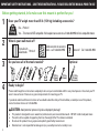
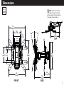
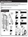
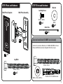
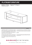
F107d INSTRUCTION MANUAL
We’ll Make It Stress-Free
If you have any questions along the way, just give us a call.
1-888-333-9952. We’re ready to help!
Scan for easy install video
san.us/793
IMPORTANT SAFETY INSTRUCTIONS – SAVE THESE INSTRUCTIONS – PLEASE READ ENTIRE MANUAL PRIOR TO USE
Before getting started, let’s make sure this mount is perfect for you!
1
Does your TV weigh more than 35 lb (15.9 kg) including accessories?
35 lb
(15.9 kg)
2
No — Perfect!
Yes — This mount is NOT compatible. Visit vuepoint.sanus.com or call 1-888-333-9952 to find a compatible mount.
What is your wall made of?
Drywall with
wood studs Perfect!
3
Solid concrete or concrete
block - call 1-888-333-9952
Do you have all of the tools needed?
Unsure? Call 1-888-333-9952
Optional
7/32 in.
(5.5 mm)
Wood
4
?
1/2 in.
(13 mm)
3/8 in.
(10 mm)
Concrete
Ready to begin?
Please read through these instructions completely to be sure you’re comfortable with this easy install process. Also check your TV
owner’s manual to see if there are any special requirements for mounting your TV.
If you do not understand these instructions or have doubts about the safety of the installation, assembly or use of this product,
contact Customer Service at 1-888-333-9952.
CAUTION: Avoid potential personal injuries and property damage!
●
●
●
●
2
This product is designed for use in wood stud, solid concrete, and concrete block walls - DO NOT install into drywall alone
The wall must be capable of supporting five times the weight of the TV and mount combined
Do not use this product for any purpose not explicitly specified by manufacturer
Manufacturer is not responsible for damage or injury caused by incorrect assembly or use
Dimensions
in.
[cm]
NOTE: TV shifts 4.3 in. (10.8 cm)
to the right or left when in the home
position. Consider this when selecting
the location of your wall mount.
7.9
[20.0]
3.9
[10.0]
2.6
[6.5]
3.0
3.9
[10.0] [7.5]
16º
3.0
[7.5]
16º
4.3
[10.8]
TOP
7.9
[20.0]
7.9
[20.0]
FRONT
7.2
[18.3]
7.6
[19.3]
2.9
[7.5]
SIDE
3
Supplied Parts and Hardware
WARNING: This product contains small items that could be a choking hazard if swallowed.
Before starting assembly, verify all parts are included and undamaged. If any parts are missing or damaged, do not return the
damaged item to your dealer; contact Customer Service. Never use damaged parts!
NOTE: Not all hardware included will be used.
TV Screws
STEP 1 Parts and Hardware
TV Bracket
TV Bracket
Extenders
M4 x 12mm
M4 x 35mm
04 x4
05 x4
M5 x 12mm
M5 x 35mm
06 x4
07 x4
02 x4
M6 x 12mm
M6 x 35mm
08 x4
TV Bracket
Interface
Screws
09 x4
Spacers
Washers
01 x1
03 x8
4
M
4/M
M6
10 x4
11 x4
5
M4 x 8mm
12 x4
STEP 2 Parts and Hardware
STEP 3 Parts and Hardware
Washer
Locking Screw
Wall Plate Template
Wall Plate Assembly
8-32 x 3/8 in.
16 x1
8-32
17 x1
Cable Ties
18 x3
14 x1
Concrete Installation Kit CMK1 (not included)
Contact Customer Service at 1-888-333-9952 to have
these additional pieces shipped directly to you.
13 x1
Lag Bolts
x4
5/16 xx 2¾ in.
5/16
in.
5/16 x 2¾ in.
15 x2
x4
.695
.350xx.075
in.
.695 xx .350
.075 in.
x4
Fischer UX 10 x 60 Anchor
5
STEP 1 Attach TV Bracket to TV
1-1 Measure Your TV Hole Pattern
Measure the width and height of your TV hole
pattern in cm.
Record your measurements:
1-2 Assemble Your TV Bracket
Determine which TV bracket configuration to use, A, B, or C
based on your TV hole pattern measurements.
Width __________cm x Height ________ cm
A
75 mm = 7.5 cm ≈ 3 in.
100 mm = 10 cm ≈ 4 in.
200 mm = 20 cm ≈ 7⅞ in.
10.0
7.5
7.5 x 7.5
10.0 x 10.0
inch dimensions are approximate
01
7.5
10.0
02
x 8mm
es
inch
cm
6
03
These smaller hole patterns only use TV bracket 01 .
Do not use the four TV bracket extenders 02 and eight screws 03 .
20.0 x 20.0
B
02
20.0 x 10.0
C
20.0
02
20.0
02
02
01
01
10.0
20.0
02
02
02
02
03
Assemble TV bracket extenders 02 onto TV bracket 01 as
illustrated.
Secure using eight screws 03 in the corner holes shown.
03
Assemble TV bracket extenders 02 onto TV bracket 01 as
illustrated.
Secure using eight screws 03 in the corner holes shown.
7
1-3 Select TV Screw
Diameter
1-4 Select TV Screw Length
Hand thread screws into the
threaded inserts on the back
of your TV to determine which
screw diameter (M4, M5, or
M6) to use.
If your TV has a flat back AND you want your TV closer to
the wall, use the shorter screws.
M4
M5
Spacers and longer screws are supplied to accommodate:
● Round/irregular back TVs
● TVs with inset mounting holes
● Extra space needed for cables
Standard configurations
are shown. For special
applications, or if you
are uncertain about your
hardware selection,
contact Customer Service
at 1-888-333-9952.
CAUTION:
Verify adequate thread
engagment with the screw or
screw/spacer combination.
M6
FLAT BACK
ROUND BACK
INSET HOLES
CABLES
- Too short will not hold the TV.
- Too long will damage the TV.
Too Short
Correct
Too Long
8
1-5 Attach TV Bracket
Position your TV bracket configuration (A or B) over your TV hole pattern - making sure the bracket is centered over the TV hole
pattern and level. Secure bracket using your screw/washer (Flat Back) or spacer/screw/washer (Round Back / Extra Space)
selection.
IMPORTANT: Ensure TV bracket is securely fastened before moving on to the next step.
03
02
01
TV Bracket
Configuration B
Illustrated
(with spacers)
NOTE: For 20.0
x 20.0 or 20.0 x 10.0 hole
patterns, you may need to
loosen the screws 03 to
align the bracket extenders
02 .
Flat Back
04 06 08
After bracket extenders
02 are secured to the
back of your TV, re-tighten
screws 03 .
10 11
Round Back / Extra Space
05 07 09
01
TV Bracket
Configuration A
Illustrated
(with spacers)
12
10 11
9
STEP 2A Attach Wall Plate - Wood Stud
CAUTION: Avoid potential personal injuries and property damage!
●
Drywall covering the wall must not exceed 5/8 in. (16 mm)
●
Minimum wood stud size: common 2 x 4 in. (51 x 102 mm) nominal 1½ x 3½ in. (38 x 89 mm)
1.
Locate your stud. Verify and mark the center of the stud by finding the stud edges using an awl, a thin nail, or an edge to
edge stud finder.
2.
Position the wall plate template 13 at your desired height and line up the holes with your stud center line. Level the template
and tape in place.
3 in.
Drill pilot holes using a 7/32 in. (5.5 mm) diameter drill bit. Remove wall plate template 13 .
(75 mm)
IMPORTANT: Be sure to drill into the center of the stud.
3.
IMPORTANT: Pilot holes must be drilled to a depth of 3 in. (75 mm).
1
2
7/32 in.
(5.5 mm)
3
≤ 5/8 in.
(16 mm)
13
13
NOTE: TV shifts
4.3 in. (10.8 cm)
to the right or left
when in the home
position. Consider
this when selecting the location of
your wall mount.
10
4.
Install wall plate assembly 14 using two lag bolts 15 . Tighten the lag bolts only until they are pulled firmly against the wall
plate.
CAUTION: Improper use could reduce the holding power of the lag bolt. DO NOT over-tighten the lag bolts.
NOTE: If needed, you can make small level adjustments to the wall plate by loosening the bottom lag bolt and shifting the wall
plate until level. Tighten the bottom lag bolt when adjustments are complete.
4
14
14
15
15
11
STEP 2B Attach Wall Plate - Solid Concrete / Concrete Block
CAUTION: Avoid potential personal injuries and property damage!
Concrete Installation Kit CMK1 is not included
●
●
●
Mount the wall plate assembly 14 directly onto the concrete surface
Minimum solid concrete thickness: 8 in. (203 mm)
Minimum concrete block size: 8 x 8 x 16 in. (203 x 203 x 406 mm)
1.
Position the wall plate template 13 on the wall at your desired height. Level the wall plate template and mark the hole
locations.
Drill two pilot holes using a 3/8 in. (10 mm) diameter masonry drill bit.
2.
(see page 5) Contact Customer Service
at 1-888-333-9952 to have the additional
hardware shipped directly to you.
IMPORTANT: Pilot holes must be drilled to a depth of 3 in. (75 mm). Never drill into the mortar between blocks.
1
2
75 mm
(3 in.)
10 mm
(3/8 in.)
13
13
NOTE: TV shifts 4.3 in.
(10.8 cm) to the right or
left when in the home
position. Consider this
when selecting the location of your wall mount.
12
3.
Remove the wall plate template 13 and insert two anchors (Fischer UX 10 x 60 - included in the Concrete Installation Kit
CMK1*).
CAUTION: Be sure the anchors are seated flush with the concrete surface.
4.
Install wall plate assembly 14 using two lag bolts and two washers (use only the lag bolts and washers from the Concrete
Installation Kit CMK1*). Tighten the lag bolts only until they are pulled firmly against the wall plate.
CAUTION: Improper use could reduce the holding power of the lag bolt. DO NOT over-tighten the lag bolts.
*Contact Customer Service at 1-888-333-9952 to have the Concrete Installation Kit CMK1 shipped directly to you.
NOTE: If needed, you can make small level adjustments to the wall plate by loosening the bottom lag bolt and shifting the wall
plate until level. Tighten the bottom lag bolt when adjustments are complete (see page 11).
3
4
*
*
14
*
13
STEP 3 Hang TV onto Wall Plate
HEAVY! You may need assistance with this step.
1.
Hang the TV onto the arm of wall plate assembly 14 by first hooking the top support, then resting the TV into place.
2.
Lock the TV to the wall plate assembly 14 with locking screw 16 and washer 17 .
IMPORTANT: This locking screw 16 must be installed to secure the TV onto the wall plate assembly 14 .
1
2
14
17
14
14
16
Manage Cables
Cables can be routed through the cable channel on the top of the arm of the wall plate assembly 14 for a cleaner look.
14
18
15
TV Adjustments
TILT ADJUSTMENT
LEVEL ADJUSTMENT
Your TV should adjust easily when moved, then stay in place.
To adjust the leveling of your TV, loosen the locking screw
16 , level your TV, then tighten locking screw 16 .
If your TV is too loose or too tight, adjust the tilt tension
knob by hand.
NOTE: Once your TV is in place, tighten the tilt tension
knob to prevent unwanted movement.
IMPORTANT: This locking screw 16 must be installed to
secure the TV onto the wall plate assembly 14 .
Tig
14
n
hte
L
oo
sen
Lo
se
o
Tilt Tension Knob
Tighten
n
16
16
REMOVING THE TV
HEAVY! You may need
assistance with this step.
To remove your TV from the wall plate assembly 14 , disconnect all cables and then reverse the procedures in STEP 3.
14
17
Features
20.0
10.0
7.5
7.5
TV bracket can be
configured to fit TV hole
patterns from 7.5 x 7.5 cm
up to 20.0 x 20.0 cm
18
20.0
10.0
Adjustments allow fingertip control
of TV or restriction of TV movement
Fully articulating arm
creates 2-point movement
for optimal viewing position
TV tilts up or down for the
perfect viewing angle
Cable channel
holds cables
along mount arm
for a clean look
Level
adjustments
create a
worry-free
installation
19
ESPAÑOL
INSTRUCCIONES DE SEGURIDAD IMPORTANTES. CONSÉRVELAS. LEA TODO EL MANUAL ANTES DE UTILIZAR ESTE PRODUCTO.
Antes de comenzar, verifiquemos que este soporte sea perfecto para usted.
1
¿Su televisor pesa más de 15.9 kg (35 libras), incluidos los accesorios?
(15.9 kg)
35 libras
No — ¡Perfecto!
Sí — Este soporte NO es compatible. Visite Vuepoint.Sanus.com o llame al 1-888-333-9952 para encontrar un soporte compatible.
2
¿De qué está hecha su pared?
3
¿Tiene todas las herramientas necesarias?
Tabiques de yeso
con montantes de ¡Perfecto!
madera
Hormigón sólido o bloques
de cemento - llame al
1-888-333-9952
¿No está seguro? Llame al
1-888-333-9952
Opcional
7/32"
(5.5 mm)
Madera
4
?
1/2"
(13 mm)
3/8"
(10 mm)
Hormigón
¿Listo para comenzar?
Lea estas instrucciones en su totalidad para estar seguro de sentirse cómodo con este fácil proceso de instalación. Consulte también
el manual del usuario de su televisor para ver si existe algún requisito especial para instalar su televisor en la pared.
Si no entiende las instrucciones o si tiene dudas acerca de la seguridad de la instalación, del ensamblado o del uso del producto,
contáctese con el servicio de atención al cliente al 1-888-333-9952.
PRECAUCIÓN: Evite lesiones y daños materiales.
●
●
●
●
20
Este producto está diseñado para ser instalado en paredes con montantes de madera. NO lo instale en una pared de yeso
únicamente.
La pared debe soportar cinco veces el peso del televisor y del soporte juntos.
No utilice este producto para ningún otro propósito que no sea el explícitamente especificado por el fabricante.
El fabricante no se responsabiliza por ningún daño o lesión resultante del montaje incorrecto o del uso indebido.
ESPAÑOL
Piezas y accesorios suministrados
ADVERTENCIA: Este producto contiene piezas pequeñas que, si fuesen tragadas, podrían producir asfixia.
Antes de iniciar el ensamblaje, compruebe que todas las piezas estén incluidas y en buenas condiciones. Si faltan piezas o
alguna está dañada, no devuelva el artículo al distribuidor; póngase en contacto con el servicio de atención al cliente. Nunca
utilice piezas deterioradas.
NOTA: No todos los accesorios incluidos deberán utilizarse.
PASO 1 Fijar la placa de sujeción al televisor
1-1 Mida el patrón de orificios del televisor
1-2 Arme la placa de sujeción del televisor
Mida en mm el ancho y el alto del patrón de orificios del
televisor.
Determine qué configuración de placa de sujeción debe usar (A, B o
C) según las medidas del patrón de orificios del televisor.
Anote las medidas:
A
Los patrones de orificios más pequeños solo requieren placa de
sujeción 01 .
No utilice las cuatro extensiones de la placa de sujeción 02 ni
los ocho tornillos 03 .
B
Ensamble las extensiones 02 de la placa de sujeción y la placa
de sujeción 01 tal como se muestra en la ilustración.
Fije colocando ocho tornillos 03 en los orificios de las esquinas
que se muestran en la imagen.
C
Ensamble las extensiones 02 de la placa de sujeción y la placa
de sujeción 01 tal como se muestra en la ilustración.
Fije colocando ocho tornillos 03 en los orificios de las esquinas
que se muestran en la imagen.
Ancho _________cm x Alto __________ cm
21
ESPAÑOL
1-3 Seleccione el diámetro
de los tornillos para el
televisor
1-4 Seleccione el largo de los tornillos para el
televisor
Enrosque manualmente los
tornillos en los encastres
roscados del dorso del televisor
a fin de determinar qué diámetro
de tornillos (M4, M5 o M6)
utilizar.
Si el dorso del televisor es plano, utilice los
tornillos cortos.
Los espaciadores y los tornillos largos se
proporcionan para:
● televisores con dorso irregular o redondeado
● televisores con orificios de montaje intercalados
● dejar un espacio adicional para cables
PRECAUCIÓN:
Verifique que el tornillo o la combinación
de tornillo y espaciador enrosquen
correctamente.
- Si el tornillo es demasiado corto, no
sostendrá el televisor.
- Si es demasiado largo, dañará el televisor.
1-5 Fije la placa de sujeción
Posicione la placa de sujeción armada sobre el patrón de orificios del televisor y verifique que esté centrada y nivelada verticalmente.
Instale las placas de sujeción usando la combinación que haya seleccionado para su televisor: tornillo corto y arandela o espaciador, o bien
tornillo largo y arandela.
PASO 2A Fijar la placa mural - ÚNICAMENTE montantes de madera
PRECAUCIÓN: Evite lesiones y daños materiales.
●
●
1.
2.
El yeso que recubre la pared no debe exceder los 16 mm (5/8’').
Tamaño mínimo del montante de madera: común 51 mm x 102 mm (2’’ x 4’'); nominal 38 mm x 89 mm (1½’’ x 3½’').
Localice un montante. Busque los bordes del montante y marque el centro con un punzón o un clavo delgado, o bien utilice un detector
de bordes de montantes.
Ubique la plantilla de placa mural 13 a la altura deseada y alinee los orificios con la línea central de los montantes. Nivele la plantilla y
fíjela con cinta adhesiva en el lugar.
3.
Con una mecha de 5.5 mm (7/32’') de diámetro, realice los orificios guía. Retire la plantilla de placa mural 13 .
IMPORTANTE: Asegúrese de perforar el centro del montante.
IMPORTANTE: Los orificios guía deben realizarse hasta una profundidad de 63.5 mm (2½'').
22
ESPAÑOL
4.
Instale el módulo de la placa mural 14 usando dos tornillos tirafondo 15 . Ajuste los tornillos tirafondo solamente hasta que queden
firmes contra la placa mural.
PRECAUCIÓN: El uso indebido podría reducir la capacidad de retención de los tornillos tirafondo. NO ajuste en exceso los
tornillos tirafondo.
NOTA: Si es necesario, puede realizar ajustes de nivel de pequeñas a la placa de pared aflojando el perno de fijación inferior y cambiar la
placa de pared hasta que nivel. Apriete el perno de fijación inferior cuando haya finalizado los ajustes.
PASO 2B Fijar la placa mural - Hormigón sólido o bloques de cemento
PRECAUCIÓN: Evite lesiones y daños materiales.
El Kit de instalación en hormigón
CMK1 no está incluido (Ver página 5)
●
Instale el módulo de la placa mural 18 directamente sobre la superficie de hormigón
●
Espesor mínimo del hormigón: 8 pulgadas (203 mm)
●
Tamaño mínimo del bloque de cemento: 8 x 8 x 16 pulgadas (203 x 203 x 406 mm)
1.
Coloque la plantilla de la placa mural 17 en la pared a la altura que desee.
Nivele la plantilla de la placa mural y marque la ubicación de los orificios.
2.
Realice los orificios guía con una mecha para mampostería de 3/8’’ (10 mm) de diámetro.
IMPORTANTE: Los orificios guía deben realizarse hasta una profundidad de 3’’ (75 mm). Nunca perfore el cemento que une los bloques.
Retire la plantilla de la placa mural 17 e introduzca tres anclajes (Fischer UX 10 x 60 - incluidos en el Kit de instalación en hormigón CMK1*).
PRECAUCIÓN: Cerciórese de que los anclajes queden nivelados respecto de la superficie de hormigón.
4. Instale el módulo de la placa mural 18 usando tres tornillos tirafondo y tres arandelas (utilizar únicamente los tornillos tirafondo y las
arandelas del Kit de instalación en hormigón CMK1*). Ajuste los tornillos tirafondo solamente hasta que queden firmes contra la placa mural.
PRECAUCIÓN: El uso indebido podría reducir la capacidad de retención de los tornillos. NO ajuste en exceso los tornillos tirafondo.
*Comuníquese con el servicio de atención al cliente al 1-888-333-9952 para solicitar que le enviemos el Kit de instalación en
hormigón CMK1.
NOTA: De ser necesario, puede realizar un pequeño ajuste de la nivelación de la placa mural. Para ello, afloje el tornillo tirafondo inferior y
luego desplace la placa mural hasta que esté nivelada. Ajuste nuevamente el tornillo tirafondo inferior cuando termine de realizar ajustes
(ver página 11).
3.
4.
Comuníquese con el servicio de atención
al cliente al 1-888-333-9952 para solicitar
que le enviemos los elementos de
sujeción adicionales.
23
ESPAÑOL
PASO 3 Colgar el televisor en la placa mural
¡ELEMENTO PESADO! Es posible que necesite ayuda en este paso.
1.
Para colgar el televisor en el brazo del módulo de la placa mural 14 , primero enganche el soporte superior y luego apoye el televisor en
su lugar.
2.
Fije el televisor al módulo de la placa mural 14 con el tornillo de seguridad 16 y una arandela 17 .
IMPORTANTE: Este tornillo de seguridad 16 debe instalarse para fijar el televisor al ensamblaje de la placa mural 14 .
Organización de cables
Si lo desea, pase el cincho sujetacable provisto 18 por el anillo del brazo del ensamblaje de la placa mural 14 , y sujete los cables del televisor
a lo largo del brazo para dar un aspecto más prolijo.
24
ESPAÑOL
Ajustes del televisor
AJUSTE DE LA INCLINACIÓN
AJUSTE DEL NIVEL
El televisor debe acomodarse fácilmente al moverlo, y luego
quedar en su lugar.
Para ajustar la nivelación de su televisor, afloje el tornillo de
seguridad 16 , nivele el televisor, y luego ajuste el tornillo de
seguridad 16 .
Si el televisor está demasiado suelto o demasiado ajustado,
ajuste la perilla de tensión de inclinación manualmente.
NOTA: Una vez que el televisor esté en su lugar, ajuste la
perilla de tensión de inclinación para evitar movimientos
indeseados.
IMPORTANTE: Este tornillo de seguridad 16 debe instalarse
para fijar el televisor al ensamblaje de la placa mural 14 .
EXTRACCIÓN DEL TELEVISOR
¡ELEMENTO PESADO!
Es posible que necesite
ayuda en este paso.
Para extraer el televisor del ensamblaje de la placa mural 14 , desconecte todos los cables y luego revierta el procedimiento descrito en el
PASO 3.
25
ESPAÑOL
Descripción
Los ajustes permiten el control
manual o la restricción del
movimiento del televisor.
El brazo completamente
articulado crea un movimiento
de 2 puntos para alcanzar una
posición de visualización óptima.
El televisor se inclina
hacia arriba / abajo para
obtener el ángulo de
visualización perfecto.
Los ajustes
de nivelación
hacen que la
instalación sea
sencilla.
26
Los canales para
cables sujetan
los cables a lo
largo del brazo
para un aspecto
prolijo.
27
Thank you for choosing Sanus Vuepoint!
Please take a moment to let us know how we did:
Call us: 1-888-333-9952
Email us: [email protected]
Leave a review: vuepoint.sanus.com
Milestone AV Technologies and its affiliated corporations and subsidiaries (collectively, “Milestone”), intend to make this manual accurate and complete.
However, Milestone makes no claim that the information contained herein covers all details, conditions, or variations. Nor does it provide for every possible
contingency in connection with the installation or use of this product. The information contained in this document is subject to change without notice or
obligation of any kind. Milestone makes no representation of warranty, expressed or implied, regarding the information contained herein. Milestone assumes no
responsibility for accuracy, completeness or sufficiency of the information contained in this document.
©2014 Milestone AV Technologies. All rights reserved. Sanus is a division of Milestone.
All other brand names or marks are used for identification purposes and are trademarks of their respective owners.
SANUS • 6436 City West Parkway • Eden Prairie, MN 55344 USA
28
6902-002070 03