1
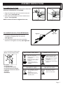
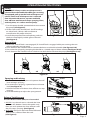
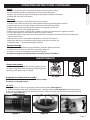
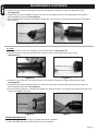
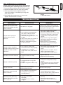
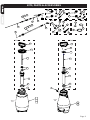
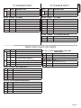
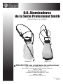
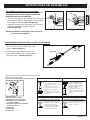
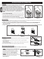
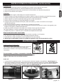
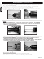
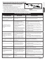
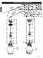
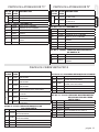
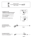
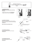
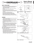
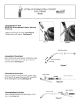
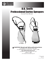
D.B. Smith
Professional Series Sprayers
Use and Care Manual
(“O” Style)
(“R” Style)
CAUTION: Read and follow all instructions
Do Not Return This Sprayer To The Store
For Help, Information or Parts, Call : 1-800-311-9903
The Fountainhead Group, Inc.
23 Garden St., New York Mills, NY 13417
1-800-311-9903
www.TheFountainheadGroup.com
Manual No. 181959
Rev B. 1/8/13
ECN13-001
5 1/2” x 8 1/2” Booklet
SAFETY PRECAUTIONS
• Read owner’s manual completely before operating this sprayer.
• Always use goggles, gloves, and protective clothing when using sprayer.
• Read and follow all instructions and cautions on label of products used in this sprayer.
• Never use flammable liquids, caustics, acids, or hot water in this tank.
• Do not leave sprayer in the sun when not in use.
• Spray when air is calm to prevent drift of chemicals.
• Do not use sprayer near open flame or anything that could cause ignition of the spray.
• Always inspect hose and all hose connections before each use. A damaged hose, or loose hose
connection can result in unintended exposure to the pressurized chemical, resulting in serious injury or
property damage.
• Do not lift or carry sprayer by the hose, shut-off valve, or extension. Carry by pump handle only,
making sure handle is properly locked in place before lifting.
• Do not pressurize with any mechanical device such as an air compressor, since this can create a
dangerous pressure level and bursting of parts resulting in serious injury. Only use original pump.
• Do not store chemicals in this tank.
• Always release pressure when sprayer is not in use and before removing pump from tank.
• Do not stand with face or body over top of tank when pumping or loosening pump, to prevent pump or
solution from striking you, resulting in serious injury.
• Clean and rinse sprayer thoroughly after each use.
• Never attempt to alter sprayer from original condition.
• Always use replacement parts from original manufacturer.
• Keep the sprayer and all chemicals out of the reach of children.
WARNING
ALWAYS CLEAN THE SPRAYER AND SHUT-OFF THOROUGHLY AFTER EACH USE
OR WHEN CHANGING APPLICATIONS AS DESCRIBED IN THE CLEANING SECTION.
FAILURE TO COMPLETELY CLEAN MAY CAUSE CROSS-CONTAMINATION.
CAUTION
Always empty, clean and dry tank, pump system, shut-off, hose, and extension after each use. FAILURE TO
DO SO MAY WEAKEN SPRAYER COMPONENTS, CAUSING COMPONENTS TO RUPTURE WHEN PRESSURIZED.
Additionally, FAILURE TO CLEAN AND PROPERLY MAINTAIN YOUR SPRAYER WILL VOID MANUFACTURER’S
WARRANTY.
WARNING
The sprayer is operated with liquid under pressure. Failure to observe caution and to follow instructions
for operating and cleaning can cause tank, hose and other parts to be weakened and rupture under
pressure. This can result in serious injury from high pressure discharge of liquids or forcible ejection of
parts. Do not use flammable materials in this sprayer. Material could ignite or explode, causing serious
injury and/or possible death. For safe use of this product, you must read and follow all instructions before
use.
TEST SPRAYER WITH WATER BEFORE USING ANY CHEMICALS.
Do not return sprayer to store, if you experience problems or have questions contact
our toll free Customer Service Center, M-F 8A.M. - 5P.M., EST, at 1-800-311-9903, or
e-mail: [email protected], or access online at: www.TheFountainheadGroup.com.
Page 2
ASSEMBLY INSTRUCTIONS
Assemble Hose To Tank
IMPORTANT: Do not attempt to heat or alter hose,
hose nut, or barb prior to assembly.
1. Align hose barb tabs, push hose barb into tank
until it stops (See Figure A).
2. Slide hose nut into place and turn clockwise to
tighten. (See Figure B).
NOTE: Do not use tools to tighten hose nut.
Figure A
Assemble Extension, Shut-Off & Nozzle
1. Install the extension onto the shut-off
assembly and tighten the nut securely.
(See Figure C)
2. Install selected nozzle onto the end of the
extension and tighten securely. (See Figure D)
SELECT USING NOZZLE CHART BELOW
(Nozzle selections vary by model)
D
A
E
C
G
B
F
H
A. Cap Nut
B. Foaming Nozzle
C. Adjustable Cone Nozzle
D. Red High-Volume Fan Nozzle
E. Yellow Low-Volume Fan Nozzle
F. Flat Seal
G. Adapter
H. Extension
Figure C
ADJUSTABLE CONE USES:
Spot spraying in or around flower
beds, trees, and shrubs.
Edging along fences, driveways,
and walkways.
Killing brush such as poison ivy,
poison oak, kudzu and wild
blackberry.
Preparing garden beds for
planting of ornamentals and
vegetables.
RED HIGH VOLUME
FAN NOZZLE USES:
Lawn replacement. Kill lawn
and weeds before planting a
new lawn.
Preparing large areas for
planting of ornamental and
vegetable gardens.
Figure B
Figure D
FOAMING NOZZLE USES:
Spot spraying in flower beds,
walkways, driveways, and
patios, around trees and shrubs.
Edging along fences, driveways
and walkways.
Killing brush such as poison
ivy, poison oak, kudzu and wild
blackberry.
YELLOW LOW VOLUME
FAN NOZZLE USES:
For precision spraying in
confined areas such as
gardens and flower beds.
Page 3
OPERATING INSTRUCTIONS
Filling
IMPORTANT: Always make sure the pressure is
released from the tank before filling or servicing.
If equipped, pull up on the knob of the pressure
release valve until all the pressure is released
from the tank. Otherwise, squeeze and hold
shut-off lever until the unit stops spraying. Then,
and only then, it is safe to remove pump.
1. Turn the pump handle counterclockwise to remove
the pump (See Figure E).
2. Fill the tank to the desired level. See fill markings
on side of tank. (Always refer to chemical
manufacturer for proper mixture).
3. Install the pump into the tank opening and turn
clockwise until tightly sealed against the tank
(See Figure F).
Figure E
Figure F
Pressurizing
1. Make sure shut-off lock is not engaged. (If shut-off lock is engaged while pressurizing, the unit
will immediately start spraying).
2. Push down on the handle and turn counterclockwise to unlock the handle (See Figure G-1G).
3. Pressurize the sprayer by pumping the handle in a smooth up and down motion (See Figure G-2G).
4. Push down on the handle and turn clockwise to lock the handle into the pump (See Figure G-3G).
1G
2G
3G
Figure G
Spraying and Locking
LEVER
1. Direct nozzle away from you and squeeze shut-off
lever to begin spraying.
2. For continuous spraying, squeeze lever and rotate
lock (See Figure H).
3. Unlock if needed and release shut-off lever to stop
spraying.
4. Turn the nozzle tip to adjust the spray pattern.
Release Tank Pressure
Figure H
Pressure Release Valve (PRV) on select models
1. NO PRV: Lay the tank on its side with the hose
outlet on the bottom. Direct the nozzle away
from you and squeeze the shut-off lever until
the unit stops spraying. (See Figure I)
2. WITH PRV: Pull up on the knob of the PRV until
all pressure is released from the tank.
(See Figure J)
Figure I
Figure J
Page 4
OPERATING INSTRUCTIONS CONTINUED
Finish
1. Depressurize the tank as described in Release Tank Pressure section.
2. Turn the pump handle counterclockwise to remove the pump.
3. Empty any remaining liquid according to the product disposal directions.
4. Follow the Cleaning instructions.
Cleaning
1. Remove the pump as described in the Finish section.
2. Fill the tank with cool, clean tap water. Replace the pump and tighten securely.
3. Agitate the tank to rinse the chemical from the tank wall and pump.
4. Remove the pump and empty the contents into gravel or bare soil.
5. Refill the tank with cool, clean tap water.
6. Make sure the pump is free of dirt or debris and reinstall into the tank. Tighten securely.
7. Pressurize the tank as described in the Pressurizing section.
8. Direct the nozzle away from you and activate the shut-off for at least 30 seconds to clean the
hose and shut-off.
9. Release pressure as described in the Release Tank Pressure section.
10. Remove the pump and empty the contents into gravel or bare soil.
11. Repeat steps 5 - 10 until thoroughly cleaned.
Sprayer Storage
1. Sprayer tank should be hung upside down, with the pump removed.
2. Do not store or leave any solution in the tank after use.
3. Store in a warm, dry location out of direct sunlight.
4. Keep the sprayer and all chemicals out of the reach of children.
MAINTENANCE
Pump Lubrication
Pump should be periodically oiled by applying 10 to
12 drops of light oil down the pump rod through the
opening in the pump cap as shown.
“O” Style
Pump Disassembly & Reassembly
“R” Style
NOTE: Remove pump from tank prior to disassembly.
As shown on varying models.
“O” Style
1. Inspect gasket. If worn or damaged, remove and replace. (See Figure 1)
2. To disassemble pump cap from pump barrel, squeeze the tabs (See Figure 2) that lock the barrel
to the cap, and while resting the extension clip on a table or bench turn the barrel counterclockwise
to unlock. (See Figure 3)
Figure 1
Figure 2
Figure 3
Page 5
MAINTENANCE CONTINUED
3. Inspect o-ring. If worn or damaged, remove and replace. Lubricate o-ring with petroleum jelly.
(See Figure 4)
4. Inspect check valve in bottom of barrel. If worn or damaged, remove and replace by pressing into
hole in bottom of barrel. (See Figure 5)
5. Re-install the barrel into the cap. While holding the cap securely, turn the barrel clockwise to lock the
tabs in place.
Figure 4
Figure 5
“R” Style
1. Inspect gasket. If worn or damaged, remove and replace. (See Figure 6)
2. To remove pump cap from pump barrel, remove screws securing pump cap to barrel.
(See Figure 7)
Figure 6
Figure 7
3. Inspect o-ring. If worn or damaged, remove and replace. Lubricate o-ring with petroleum jelly.
(See Figure 8)
4. Inspect check valve in bottom of barrel. If worn or damaged, remove and replace by pressing into
hole in bottom of barrel. (See Figure 9)
5. Insert the pump handle assembly into the barrel. Align the holes in the pump cap and barrel. Reinstall
screws and tighten securely.
Figure 8
Figure 9
Nozzle Maintenance
1. If nozzle clogs, remove and disassemble the nozzle assembly.
2. Clean the openings of any obstructions and reassemble.
Page 6
Shut-off Maintenance (Smith Pro II)
Always depressurize sprayer before maintenance
by activating shut-off and spraying contents out.
1. Unscrew the handle from the shut-off assembly.
2. Remove the filter from the shut-off assembly.
3. Clean any debris from inside the handle,
shut-off assembly, or the filter by rinsing with
cool, clean water.
4. Reassemble the components as shown and
tighten all connections securely.
C
A
B
A. Handle
B. Filter
C. Shut-off Assembly
TROUBLESHOOTING
TROUBLE
LOOK FOR
REMEDY
Sprayer starts to spray when
pumping or sprayer will not
stop spraying when shut-off
lever is released.
Shut-off lock is engaged.
Squeeze shut-off lever and rotate the
lock towards the nozzle as described in
Spraying and Locking section.
Sprayer leaks at pump or
sprayer does not build
pressure.
1. Dirt or debris on pump gasket
(#2F, #5G, or #6B) or closure.
2. Chipped, torn, swollen, or
defective pump gasket (#2F, #5G,
or #6B).
3. Check valve (#2G, #5H, or #6A) at
bottom of pump assembly.
4. Worn or damaged o-ring (#2D
or #6C) on piston.
1. Clean dirt or debris from gasket
(#2F, #5G, or #6B) or closure.
2. Remove old gasket (#2F, #5G, or #6B)
and replace with new as described
in Pump Disassembly & Reassembly
section.
3. Replace if missing or damaged as
described in Pump Disassembly &
Reassembly section.
4. Replace if worn or damaged as
described in Pump Disassembly &
Reassembly section.
Sprayer material overflows
through pump barrel or pump
handle rises when handle is
unlocked.
1. Dirt or debris under check
valve (#2G, #5H, or 6A) on pump.
2. Chipped, torn, or swollen
pump check valve (#2G, #5H, or
#6A).
1. Clean check valve (#2G, #5H, or 6A)
and valve sealing surface on
pump.
2. Replace check valve (#2G, #5H, or
#6A) as described in Pump
Disassembly & Reassembly section.
Hose leaks at tank or shut-off.
1. Loose hose.
2. Cracked, swollen, or faulty
hose.
1. Tighten hose nut.
2. Replace shut-off assembly.
Sprayer is difficult to pump.
1. Damaged piston o-ring (#2D
or #6C).
2. Piston o-ring (#2D or #6C) is dry.
1. Replace piston o-ring as described in
Pump Disassembly & Reassembly
section.
2. Lubricate piston o-ring as described
in Pump Disassembly & Reassembly
section.
Sprayer tank leaks.
Evidence of spray material
escaping from the tank.
Replace entire sprayer.
Nozzle drips when shut-off
lever is released.
1. Dirt or debris in shut-off valve.
2. Damaged o-ring or seal in
shut-off (kit #11).
1. Clean shut-off as described in
Shut-off Maintenance section.
2. Service shut-off seals as described in
Maintenance service kit #11.
Nozzle tip leaks, poor spray
pattern, partial spray or complete stoppage.
1. Flat seal is missing or
damaged.
2. Spray extension or nozzle
clogged.
1. Replace flat seal at extension tip
(kit #11).
2. Remove nozzle and clean as
described in Nozzle Maintenance
section.
Page 7
KITS, PARTS & ACCESSORIES
9B
9A
8-1
8-2
11D
7-18
7-14
KIT #10
9C
9D
KIT #9
8-3
11B
11C
9E
10C
10E
10A
10F
9F
10D
KIT #11
11A
10B
11E
11A
11B
KIT #6
6A
11C
7-SS
7-21
11E
6C
6B
11G
11F
11F
11D
KIT #5
KIT #2
2B
5A
5B
2A
5C
2C
5D
2D
5E
6C
5F
2E
5G
2F
2G
5H
4
1-1
“O”
1-2
1-3
“R”
3-2
3-3
Page 8
“O” SPRAYER PARTS
KEY#
1
-1
-2
-3
PART# DESCRIPTION
KEY#
PART# DESCRIPTION
181052
181036
181120
-2
3
-3
4
181828
181837
180836
1 GALLON “O” TANK
2 GALLON “O” TANK
3 GALLON “O” TANK
178040
180279
180278
180429
178041
178039V
171015V
2 GALLON “R” TANK (INCLUDES KEY #4)
3 GALLON “R” TANK (INCLUDES KEY #4)
PRV ASSEMBLY
KIT #5 181911 “R” PUMP
KIT #2 180398 “O” PUMP
2A
2B
2C
2D
2E
2F
2G
“R” SPRAYER PARTS
“O” PUMP CAP
“O” PUMP HANDLE
“O” PUMP ROD
“O” PUMP PISTON ASSEMBLY
“O” PUMP BARREL
“O” PUMP GASKET, VITON
CHECK VALVE, VITON
5A
5B
5C
5D
5E
181830
182129
171002
181835
181834
“R” PUMP HANDLE
“R” PUMP SCREW (2)
“R” PUMP COVER
“R” PUMP ROD
“R” PUMP PISTON ASSEMBLY
5F
5G
5H
171003 “R” PUMP BARREL
181203 “R” PUMP GASKET
171015V CHECK VALVE, VITON
KIT #6 182046 “R” PUMP SERVICE KIT
6A
6B
6C
171015V CHECK VALVE, VITON
181203 “R” PUMP GASKET
180861 “R” PUMP PISTON O-RING
SMITH PRO II SHUT-OFF PARTS
KEY#
PART# DESCRIPTION
-14 181845
-18 181843
7 -21 181824
-SS 182112
-1
8 -2
-3
181817
181818
181819
14” EXTENSION ASSEMBLY, SMITH PRO II
18” EXTENSION ASSEMBLY, SMITH PRO II
21” EXTENSION ASSEMBLY, SMITH PRO II
21” EXTENSION ASSEMBLY,
STAINLESS STEEL, SMITH PRO II
SHUT-OFF ASSEMBLY, SMITH PRO II, 1 GAL
SHUT-OFF ASSEMBLY, SMITH PRO II, 2 GAL
SHUT-OFF ASSEMBLY, SMITH PRO II, 3 GAL
KIT #11 181910 SMITH PRO II SHUT-OFF
SERVICE KIT
11A
11B
11C
11D
11E
11F
11G
181493
181840
181231
181468
181812
181810
181805
VALVE BODY O-RING
POPPET SEAL
BARB O-RING
FILTER
FLAT NOZZLE SEAL (2)
WAND O-RING
ADJUSTABLE NOZZLE O-RING
KIT #9 181869 POLY NOZZLE KIT
9A
9B
9C
9D
9E
9F
181822
180168
180097
180266
181812
181804
POLY ADJUSTABLE NOZZLE
YELLOW FLAT FAN NOZZLE (LOW VOLUME)
RED FLAT FAN NOZZLE (HIGH VOLUME)
FOAMING NOZZLE
FLAT NOZZLE SEAL
NOZZLE CAP NUT
KIT #10 181870 BRASS NOZZLE KIT
10A
10B
10C
10D
10E
10F
181823
180168
180097
180266
181812
181804
BRASS ADJUSTABLE NOZZLE
YELLOW FLAT FAN NOZZLE (LOW VOLUME)
RED FLAT FAN NOZZLE (HIGH VOLUME)
FOAMING NOZZLE
FLAT NOZZLE SEAL
NOZZLE CAP NUT
Page 9
SERVICE KITS, PARTS & ACCESSORIES ARE AVAILABLE BY CONTACTING
The Fountainhead Group, Inc. - Customer Service Center
Monday - Friday 8 A.M. - 5 P.M., EST
Toll Free: 1-800-311-9903
or
e-mail: [email protected]
or
Access online at: www.TheFountainheadGroup.com
Page 10
D.B. Atomizadores
de la Serie Profesional Smith
Manual de uso y cuidado
(Estilo “O”)
(Estilo “R” )
PRECAUCIÓN: Lea y siga todos las instrucciones
No devuelva este atomizador a la tienda
Para obtener ayuda, información o piezas, llame al:
1-800-311-9903
The Fountainhead Group, Inc.
23 Garden St., New York Mills, NY 13417
1-800-311-9903
www.TheFountainheadGroup.com
Manual No. 181959
Rev B. 1/8/13
ECN13-001
PRECAUCIONES DE SEGURIDAD
• Lea todo el manual del usuario antes de operar este atomizador.
• Siempre utilice gafas de seguridad, guantes y ropa protectora cuando use el atomizador.
• Lea y siga todas las instrucciones y precauciones que se muestran en la etiqueta de los productos que se
usan en este atomizador.
• Nunca utilice líquidos inflamables, agentes cáusticos, ácidos o agua caliente en este tanque.
• No deje el atomizador expuesto al sol cuando no esté en uso.
• Utilice el atomizador cuando no haya viento para evitar el desplazamiento de sustancias químicas.
• No use el atomizador cerca de llamas o agentes que pudieran ocasionar que se encienda la solución de
rociado.
• Siempre revise la manguera y todas las conexiones de la misma antes de cada uso. Una manguera
dañada o una con exión suelta pueden ocasionar una exposición no deseada a la sustancia química
presurizada, lo cual podría provocar lesiones graves o daños a la propiedad.
• No levante ni transporte el atomizador por la manguera, la válvula de cierre o extensión. Cargue la
bomba por el mango solamente, cerciorándose de que el mango esté debidamente enganchado en
posición antes de levantar.
• No presurice con ningún dispositivo mecánico, como un compresor de aire, ya que puede generar
niveles de presión peligrosos y algunas piezas podrían estallar, lo cual ocasionaría lesiones graves. Sólo
use la bomba original.
• No almacene sustancias químicas en este tanque.
• Siempre alivie la presión cuando el rociador no está en uso y antes de quitar la bomba del tanque.
• No se pare con lacara o el cuerpo sobre la parte superior del tanque cuando bombea o afloja la bomba,
para evitar que la bomba o la solución le haga contacto con su querpo, resultando en lesión grave.
• Limpie y enjuague el atomizador completamente después de cada uso.
• Nunca intente modificar la condición original del atomizador.
• Siempre utilice las piezas de reemplazo del fabricante original.
• Mantenga el atomizador y todas las sustancias químicas fuera del alcance de los niños.
ADVERTENCIA
SIEMPRE LIMPIE EL ROCIADOR Y CIERRELO BIEN DESPUÉS DE CADA USO O CUANDO
CAMBIE LAS APLICACIONES COMO SE DESCRIBE EN LA SECCIÓN LIMPIEZA. EL NO
CUMPLIR CON LIMPIAR COMPLETAMENTE EL ROCIADOR PODRÍA PROVOCAR
CONTAMINACIÓN CRUZADA.
PRECAUCIÓN:
Siempre vacíe, limpie y seque el tanque, el sistema de bomba, cierre, manguera y extensión después de
cada uso. Si no lo hace, los componentes del atomizador podrían deteriorarse y romperse cuando estén
presurizados. Si no limpia el atomizador y no le da un mantenimiento adecuado, se cancelará la garantía
del fabricante.
ADVERTENCIA
El atomizador funciona con líquido a presión. Si no lo maneja con cuidado o no sigue las instrucciones de
operación y limpieza, podría ocasionar el deterioro o la ruptura del tanque, manguera y otras piezas que
están bajo presión. Esto puede provocar lesiones graves debido a la descarga de líquidos a alta presión o
a la expulsión forzada de las piezas. No use materiales inflamables en este atomizador. El material podría
encenderse o explotar y provocar lesiones graves y/o muerte. Para usar este producto de manera segura,
debe leer y seguir todas las instrucciones antes de usarlo.
PRUEBE EL ATOMIZADOR CON AGUA ANTES DE USAR SUSTANCIAS QUÍMICAS.
No devuelva el atomizador a la tienda, si tiene problemas o preguntas, comuníquese
con nuestro Centro de servicio al cliente llamando a la línea gratuita 1-800-311-9903,
de lunes a viernes de 8 A.M. a 5 P.M., hora del este, escribiendo por correo electrónico a:
[email protected] o accediendo en línea a: www.TheFountainheadGroup.com.
página 12
INSTRUCCIONES DEL ENSAMBLAJE
Ensamble la manguera en el tanque
IMPORTANTE: No intente calentar ni alterar la
manguera, tuerca de manguera o conector
dentado antes del ensamblado.
1. Alinee las lengüetas de la espiga de la manguera,
presione la espiga de la manguera en el tanque
hasta que se detenga. (Vea la Figura A).
2. Deslice la tuerca de la manguera hasta su lugar
y gire en sentido horario para ajustar.
(Vea la Figura B).
Figura A
Figura B
NOTA: No utilice herramientas para ajustar la
tuerca de la manguera.
Ensamblado de la extensión, el cierre y la boquilla
1. Instale la extensión en el dispositivo de
cierre y ajuste la tuerca hasta que esté
segura. (Vea la Figura C)
2. Instale la boquilla seleccionada en el
extremo de la extensión y apriete hasta
que esté segura. (Vea la Figura D)
Figura C
Figura D
SELECCIONE UTILIZANDO LA TABLA DE BOQUILLAS QUE SE
MUESTRA A CONTINUACIÓN.
(Las selecciones de boquilla varían por modelo) Usos de las boquillas cono ajustables: Usos de las boquillas espumantes:
D
A
E
C
G
B
F
H
Rociado localizado en o alrededor de
arriates, árboles o arbustos.
Bordes a lo largo de cercas, entradas
y caminos.
Destrucción de malezas, por
ejemplo, hiedra venenosa, roble
venenosa, kudzu y zarzamora
silvestre
Preparación de arriates de jardín
para sembrar plantas ornamentales
y vegetales.
A. Tuerca ciega
B. Boquilla para espuma
C. Boquilla de cono adjustable
D. Boquilla roja con ventilador
para alto volumen
E. Boquilla amarilla con ventilador
para bajo volumen
F. Sello plano
G. Adaptador
H. Extensión
Rociado localizado de arriates,
caminos, entradas y patios,
alrededor de árboles y arbustos.
Bordes a lo largo de cercas,
entradas y caminos.
Destrucción de malezas, por
ejemplo, hiedra venenosa, roble
venenoso, kudzu y zarzamora
silvestre.
Usos de las boquillas roja con Usos de las boquillas amarilla con
ventilador para alto volumen:
ventilador para bajo volumen:
Reemplazo de césped. Mate el
césped y las malezas antes de
sembrar el césped nuevo.
Preparación de áreas grandes
para el sembrado de plantas
ornamentales y vegetales.
Para un rocío de precisión en
zonas confinadas tales como
jardines y maceteros.
página 13
INSTRUCCIONES DE OPERACIÓN
Llenado
IMPORTANTE: Siempre asegúrese de que se ha liberado
la presión del tanque antes de llenar o utilizar. Si
provista, jale hacia arriba la perilla de la válvula de
liberación de presión hasta que se libere toda la presión
del tanque. De lo contrario, apriete y sostenga la palanca
de la válvula de cierre hasta que la unidad deje de rociar.
Después, y solamente después, es seguro quitar la
bomba.
1. Gire el mango de la bomba en sentido antihorario para quitar
la bomba (Vea la Figura E).
2. Llene el tanque al nivel deseado. Ver llenan señales en el lado
del tanque. (Consulte siempre las intrucciones del fabricante
del producto química para la mezcla apropiada).
3. Coloque la bomba en el orificio del tanque y gírela en sentido
horario hasta ajustarla frimemente al tanque. (Vea la Figura F).
Figura E
Figura F
Presurización
1. Asegúrese de que el seguro del mango de cierre no esté trabado (si el seguro del mango de cierre está trabado
durante la presurización, la unidad comenzará a rociar de immediato.
2. Empuje hacia abajo el mango y gírelo en sentido antihorario para destrabar el mango (Vea la Figura G-1G).
3. Presurice el atomizador, bombeando el mango con un movimiento uniforme hacia arriba y hacia abajo.
(Vea la Figura G-2G).
4. Empuje el mango hacia abajo y gírelo en sentido horario para trabar el mango en la bomba (Vea la Figura G-3G)
1G
2G
3G
Figura G
Atomizar y asegurar
PALANCA
1. Dirija la boquilla lejos de usted y presione la palanca de cierre para empezar
a atomizar.
2. Para atomizar de forma continua, presione la palanca y gire el seguro.
(Vea la Figura H)
3. Retire el seguro si es necesario y suelte la palanca del dispositivo de cierre
para dejar de atomizar.
4. Gire la punta de la boquilla para ajustar el patrón del rociado.
Figura H
Libere la presión del tanque
Válvula de liberación de presión (PRV) en modelos seleccionados
1. SIN PRV: Coloque el tanque de costado con la
salida de la manguera en la parte inferior. Dirija
la boquilla en sentido contrario a usted y
presione la palanca de cierre hasta que la
unidad deje de rociar. (Vea la Figura I)
2. CON PRV: Jale hacia arriba la perilla de la
válvula de liberación de presión hasta que toda
la presión del tanque se haya liberado.
(Vea la Figura J)
Figura I
Figura J
página 14
INSTRUCCIONES DE OPERACIÓN (continuación)
Finalización
1. Despresurice el tanque según se describe en la sección Libere la presión del tanque.
2. Gire el mango de la bomba en sentido antihorario para quitar la bomba.
3. Vacíe todo el líquido restante de acuerdo con las intrucciones de desecho del producto.
4. Siga las instrucciones de Limpieza.
Limpieza
1. Quite la bomba según se describe en la sección Finalización.
2. Llene el tanque con agua de grifo fresca y limpia. Vuelva a colocar la bomba y ajústela firmemente.
3. Agite el tanque para quitar el producto químico de la pared del tanque y la bomba.
4. Quite la bomba y vacíe el contenido sobre gravilla o suelo descubierto.
5. Vuelva a llenar el tanque con agua de grifo fresca y limpia.
6. Asegúrese de que la bomba esté limpia y libre de residuos, y vuelva a instalarla en el tanque.
Ajústela firmemente.
7. Presurice el tanque tal como se describe en la sección Presurización.
8. Dirija la boquilla lejos de usted y active el dispositivo de cierre durante por lo menos 30 segundos para
limpiar la manguera y el dispositivo de cierre.
9. Libere la presión tal come se describe en la sección Libere la presión del tanque.
10. Quite la bomba y vacíe el contenido sobre gravilla o suelo descubierto.
11. Repita los pasos 5 a 10 hasta que la unidad esté completamente limpia.
Alamacenamiento del atomizador
1. El tanque del atomizador debe colgarse en posición invertida y sin la bomba.
2. No almacene ni deje solución dentro del tanque después del uso.
3. Guárdelo en un lugar templado y seco, alejado de la luz solar directa.
4. Mantenga el atomizador y todos los productos químicos lejos del alcance de los niños.
MANTENIMIENTO
Lubricación de la bomba
La bomba se debe aceitar periódicamente aplicando
10 ó 12 gotas de aceite liviano en la varilla de la
bomba por la abertura de la tapa de la bomba como
se muestra.
Desensamblar y volver a ensamblar la bomba
Estilo “O”
Estilo “R”
NOTA: Saque la bomba del tanque antes de desensamblar.
Según se muestra en la variedad de modelos.
Estilo “O”
1. Inspeccione la empaquetadura. Si está gastada o dañada, sáquela y reemplácela. (Vea la Figura 1)
2. Para desensamblar la tapa de la bomba o el cilindro de la bomba, apriete las trabillas (Vea la Figura 2)
que traban el cilindro a la tapa, y mientras apoya el sujetador de extensión sobre una mesa o banco,
gire el cilindro en sentido antihorario para destrabar.(Vea la Figura 3)
Figura 1
Figura 2
Figura 3
página 15
MANTENIMIENTO (continuación)
3. Inspeccione la junta tórica. Si está gastada o dañada, sáquela y reemplácela. Lubrique la junta tórica con
gel de petróleo. (Vea la Figura 4)
4. Inspeccione la válvula de retención en el fondo del cilindro. Si está gastada o dañada, sáquela y
reemplácela presionando en el orificio en el fondo del cilindro. (Vea la Figura 5)
5. Reinstale el cilindro en la tapa. Mientras sujeta la tapa firmemente, gire el cilindro en sentido horario
para fijar las trabillas en su lugar.
Figura 4
Figura 5
Estilo “R”
1. Inspeccione la empaquetadura. Si está gastada o dañada, sáquela y reemplácela. (Vea la Figura 6)
2. Para sacar la tapa de la bomba del cilindro de la bomba, retire los tornillos que aseguran la tapa de
la bomba al tubo. (Vea la Figura 7)
Figura 6
Figura 7
3. Inspeccione la junta tórica. Si está gastada o dañada, sáquela y reemplácela. Lubrique la junta tórica con
gel de petróleo. (Vea la Figura 8)
4. Inspeccione la válvula de retención en el fondo del cilindro. Si está gastada o dañada, sáquela y
reemplácela presionando en el orificio en el fondo del cilindro. (Vea la Figura 9)
5. Inserte el ensamblado del mango de la bomba en el cilindro de la bomba. Alinee los orificios de la tapa
de la bomba y el cilindro. Coloque nuevamente los tornillos y ajústelos firmemente.
Figura 8
Figura 9
Mantenimiento de la boquilla
1. Si la boquilla se atasca, retírela y desarme el ensamblaje de la boquilla.
2. Retire todas las obstrucciones presentes en las aberturas y vuelva a ensamblar
página 16
Mantenimiento del dispositivo de cierre (Smith Pro)
Siempre despresurice el atomizador antes de darle
mantenimiento al activar el cierre y atomizador los
contenidos hacia afuera.
A
B
1. Destornille el mango del dispositvo de cierre.
2. Retire el filtro del dispositivo de cierre.
3. Limpie todo residuo presente en el interior del mango
A. Mango
y del despositivo de cierre o en el asiento de válvula filtro.
B. Filtro
C. Dispositivo de cierre
4. Vuelva a ensamblar los componentes según se muestra en la
figura y apriete todas las conexiones hasta que queden aseguradas.
C
SOLUCIÓN DE PROBLEMAS
PROBLEMA
BUSCAR
SOLUCIÓN
El atomizador empieza a rociar
al bombear o el atomizador no
deja de rociar cuando el gatillo
de cierre se libera.
El seguro del dispositivo de cierre
está activado.
Presione la palanca de cierre y suelte el seguro.
Vea la sección Atomizar y asegurar.
El atomizador tiene una
pérdida en la bomba o el
atomizador no acumula
presión.
1. Hay suciedad o residuos en
la empaquetadura de la
bomba (No.2F, No.5G o No.6B)
o en el cierre.
2. Empaquetadura de bomba
(No.2F, No.5G o No.6B) astillada,
rasgada, dilatada o
defectuosa.
3. Revise la válvula (No.2G, No.5H
o No.6A) en la parte inferior del
ensamblado de la bomba.
4. Junta tórica gastada o dañada
(#2D ó #6C) sobre el pistón.
1. Limpie la suciedad o los residuos de la
empaquetadura (No.2F, No.5G o No.6B) o el
cierre.
2. Retire la empaquetadura (No.2F, No.5G o
No.6B) y reemplácela con una nueva como se
describe en la sección Desensamblar y volver a
ensamblar la bomba.
3. Reemplace ante ausencia o daños como se
describe en la sección Desensamblar y volver a
ensamblar la bomba.
4. Reemplace si está gastada o dañadacomo se
describe en la sección Desensamblar y volver a
ensamblar la bomba.
El material del atomizador se
derrama por el cilindro de
la bomba o el mango de la
bomba se eleva cuando se lo
destraba.
1. Suciedad o residuos debajo
de la válvula de retención
(No.2G, No.5H o No.6A) de la
bomba.
2. Válvula de retención (No.2G,
No.5H o No.6A) de bomba
astillada rasgada o dilatada.
1. Limpie la válvula de retención (No.2G, No.5H
o No.6A) y la superficie sellada de la válvula
de la bomba.
2. Reemplace la válvula de retención (No.2G,
No.5H o No.6A) como se describe en la sección
Desensamblar y volver a ensamblar la bomba.
La manguera tiene una pérdida
en el tanque o en el dispositivo
de cierre.
1. Manguera suelta.
2. Manguera agrietada, dilatada o
defectuosa.
1. Ajuste la tuerca de manguera.
2. Reemplace el conjunto de cierre.
Atomizador difícil de bombear.
1. La junta tórica del pistón
(No.2D o No.6C) está dañada.
2. La junta tórica del pistón
(No.2D o No.6C) está seca.
1. Reemplace la junta tórica del pistón come se
describe en la sección Desensamblar y volver a
ensamblar la bomba.
2. Lubrique la junta tórica del pistón como se
describe en la sección Desensamblar y volver a
ensamblar la bomba.
El tanque del atomizador tiene
una pérdida.
Hay evidencia de escape del
material de rociado del tanque.
Reemplace todo el atomizador.
La boquilla gotea cuando se
suelta la palanca de la válvula
de paso.
1. Suciedad o residuos en la
válvula del dispositivo de cierre.
2. Junta tórica o sello dañado en
el dispositivo de cierre (Kit
No.11)
1. Limpie el dispositivo de cierre tal como se
describe en la sección Mantenimiento del
dispositivo de cierre.
2. Déle mantenimiento a los sellos de cierre tal
como se describe en juego de mantenimiento
No.11.
La punta de la boquilla
sechorrea, patrón de aspersión
débil, aspersión parcial o
bloqueo completo.
1. Falta el sello plano o está
dañado.
2. La extensión de aspersión o la
boquilla están bloqueadas.
1. Reemplace el sello plano en la punta de la
extensión (juego No.11).
2. Retire la boquilla y limpie tal como se describe
en la sección Mantenimiento de la boquilla.
página 17
JUEGOS, PIEZAS Y ACCESORIOS
9B
9A
8-1
8-2
11D
7-21
7-18
7-14
KIT No.10
9C
9D
KIT No.9
8-3
11B
11C
9E
10B
10C
10E
10A
10F
9F
10D
KIT No.11
11A
11E
11A
11B
6A
KIT #6
11C
7-SS
11E
6C
6B
11G
11F
11F
11D
KIT No.5
KIT No.2
5A
2B
5B
2A
5C
5D
2C
5E
2D
6C
5F
2E
5G
2F
1-1
“O”
5H
4
2G
1-2
1-3
“R”
3-2
3-3
página 18
PARTES DEL ATOMIZADOR “O”
No. DE No. DE DESCRIPCIÓN
CLAVE PIEZA
1
-1
-2
-3
181052
181036
181120
TANQUE “O” DE 1 GALÓN
TANQUE “O” DE 2 GALONES
TANQUE “O” DE 3 GALONES
KIT No.2 180398 LA BOMBA “O”
2A
2B
2C
178040
180279
180278
TAPA “O” DE LA BOMBA
MANGO “O” DE LA BOMBA
VARILLA “O” DE LA BOMBA
ENSAMBLADO DEL PISTÓN “O” DE LA
180429
BOMBA
178041 CILINDRO “O” DE LA BOMBA
EMPAQUETADURA “O” DE LA BOMBA,
178039V
VITON
171015V VÁLVULA DE RETENCIÓN, VITON
2D
2E
2F
2G
PARTES DEL ATOMIZADOR “R”
No. DE No. DE DESCRIPCIÓN
CLAVE PIEZA
-2
3
-3
4
TANQUE “R” DE 1 GALÓN (INCLUYE
CLAVE NO.4)
TANQUE “R” DE 2 GALONES (INCLUYE
181837
CLAVE NO.4)
180836 ENSAMBLAJE DEL PRV
181828
KIT No.5 181911 LA BOMBA “R”
5A
5B
5C
5D
5E
5F
5G
5H
181830
182129
171002
181835
MANGO “R” DE LA BOMBA
TORNILLO “R” DE LA BOMBA (2)
CUBIERTA “R” DE LA BOMBA
VARILLA “R” DE LA BOMBA
ENSAMBLADO DEL PISTÓN “R” DE LA
181834
BOMBA
171003 CILINDRO “O” DE LA BOMBA
181203 EMPAQUETADURA “R” DE LA BOMBA
171015V VÁLVULA DE RETENCIÓN
KIT No.6 182046 JUEGO DE MANTENIMIENTO
DE BOMBA “R”
6A
6B
6C
171015V VÁLVULA DE RETENCIÓN
181203 EMPAQUETADURA “R” DE LA BOMBA
ANILLO “O” DEL PISTÓN “R” DE LA
180861
BOMBA
PIEZAS DE CIERRE SMITH PRO II
No. DE No. DE DESCRIPCIÓN
CLAVE PIEZA
-14 181845
-18 181843
7
-21 181824
-SS 182112
8
-1
181817
-2
181818
-3
181819
ENSAMBLADO DE LA EXTENSIÓN DE 14”,
SMITH PRO II
ENSAMBLADO DE LA EXTENSIÓN DE 18”,
SMITH PRO II
ENSAMBLADO DE LA EXTENSIÓN DE 21”,
SMITH PRO II
ENSAMBLADO DE LA EXTENSIÓN DE 21”,
ACERO INOXIDABLE, SMITH PRO II
ENSAMBLADO DEL CIERRE SMITH PRO II,
1 GALÓN
ENSAMBLADO DEL CIERRE SMITH PRO II,
2 GALONES
ENSAMBLADO DEL CIERRE SMITH PRO II,
3 GALONES
KIT No.9 181869 JUEGO DE BOQUILLA DE
POLICARBONATO
9A
9D
9E
181822 BOQUILLA DE POLICARBONATO AJUSTABLE
BOQUILLA AMARILLA DE VENTILADOR PLANO
180168
(BAJO VOLUMEN)
BOQUILLA ROJA DE VENTILADOR PLANO
180097
(ALTO VOLUMEN)
180266 BOQUILLA PARA ESPUMA
181812 SELLO DE BOQUILLA PLANA
9F
181804 TUERCA CIEGA DE BOQUILLA
9B
9C
KIT No.10 181870 JUEGO DE BOQUILLA DE COBRE
10A 181823
10B 180168
10C 180097
10D 180266
10E 181812
10F 181804
BOQUILLA DE COBRE AJUSTABLE
BOQUILLA AMARILLA DE VENTILADOR
PLANO (BAJO VOLUMEN)
BOQUILLA ROJA DE VENTILADOR
PLANO (ALTO VOLUMEN)
BOQUILLA PARA ESPUMA
SELLO DE BOQUILLA PLANA
TUERCA CIEGA DE BOQUILLA
KIT No.11 181910 JUEGO DE MANTENIMIENTO
DE DESPOSITIVO DE CIERRE
SMITH PRO II
11A
11B
11C
11D
11E
11F
11G
181493
181840
181231
181468
181812
181810
181805
ANILLO “O” DEL CUERPO DE LA VÁLVULA
SELLO DEL ASIENTO
JUNTA TÓRICA DEL CONECTOR
FILTRO
SELLO DE BOQUILLA PLANA (2)
ANILLO “O” DE VARILLA
ANILLO “O” DE BOQUILLA AJUSTABLE
página 19
LOS JUEGOS DE REPARACIÓN, PIEZAS Y ACCESORIOS SE ENCUENTRAN
DISPONIBLES COMUNICÁNDOSE A
The Fountainhead Group, Inc. - Centro deservicio al cliente
De lunes a viernes de 8 A.M. a 5 P.M., EST
Llame sin costo al: 1-800-311-9903
o
Correo electrónico: [email protected]
o
Ingrese en línea a: www.TheFountainheadGroup.com
página 20