1
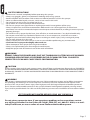
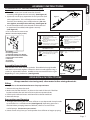
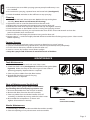
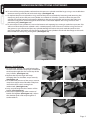
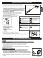
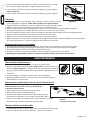
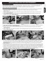
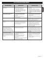
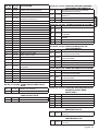
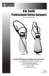
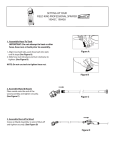
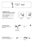
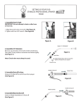
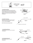
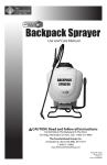
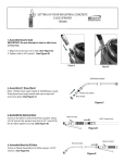
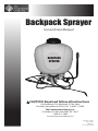
Backpack Sprayer
Use and Care Manual
BACKPACK
SPRAYER
CAUTION: Read and follow all instructions
Do Not Return This Backpack To The Store
For Help, Information or Parts, Call : 1-800-311-9903
The Fountainhead Group, Inc.
23 Garden St., New York Mills, NY 13417
1-800-311-9903
www.TheFountainheadGroup.com
Manual No. 181623
Rev F. 1/14/13
ECN13-010
5 1/2 x 8 1/2” Booklet
SAFETY PRECAUTIONS
• Read owner’s manual completely before operating this sprayer.
• Always use goggles, gloves, and protective clothing when using sprayer.
• Read and follow all instructions and cautions on label of products used in this sprayer.
• Never use flammable liquids, caustics, acids, or hot water in this tank.
• Do not leave sprayer in the sun when not in use.
• Spray when air is calm to prevent drift of chemicals.
• Do not use sprayer near open flame or anything that could cause ignition of the spray.
• Always inspect hose and all hose connections before each use. A damaged hose, or loose hose
connection can result in unintended exposure to the pressurized chemical, resulting in serious injury or
property damage.
• Do not lift or carry sprayer by the hose, shut-off valve, or wand extension. Carry by the handle only.
• Do not pressurize with any mechanical device such as an air compressor, since this can create a
dangerous pressure level and bursting of parts resulting in serious injury. Only use original pump.
• Do not store chemicals in this tank.
• Always release pressure when sprayer is not in use and before performing any maintenance.
• Clean and rinse sprayer thoroughly after each use.
• Never attempt to alter sprayer from original condition.
• Always use replacement parts from original manufacturer.
• Keep the sprayer and all chemicals out of the reach of children.
WARNING
ALWAYS CLEAN THE SPRAYER AND SHUT-OFF THOROUGHLY AFTER EACH USE OR WHEN
CHANGING APPLICATIONS AS DESCRIBED IN THE CLEANING SECTION. FAILURE TO
COMPLETELY CLEAN MAY CAUSE CROSS-CONTAMINATION.
CAUTION
Always empty, clean and dry tank, pump system, shut-off, hose, and extension after each use. FAILURE TO
DO SO MAY WEAKEN SPRAYER COMPONENTS, CAUSING COMPONENTS TO RUPTURE WHEN PRESSURIZED.
Additionally, FAILURE TO CLEAN AND PROPERLY MAINTAIN YOUR SPRAYER WILL VOID MANUFACTURER’S
WARRANTY.
WARNING
The sprayer is operated with liquid under pressure. Failure to observe caution and to follow instructions
for operating and cleaning can cause tank, hose and other parts to be weakened and rupture under
pressure. This can result in serious injury from high pressure discharge of liquids or forcible ejection of
parts. Do not use flammable materials in this sprayer. Material could ignite or explode, causing serious
injury and/or possible death. For safe use of this product, you must read and follow all instructions before
use.
TEST SPRAYER WITH WATER BEFORE USING ANY CHEMICALS.
Do not return sprayer to store, if you experience problems or have questions contact
our toll free Customer Service Center, M-F 8AM - 5PM, EST, at 1-800-311-9903, or e-mail:
[email protected], or access online at: www.TheFountainheadGroup.com.
Page 2
ASSEMBLY INSTRUCTIONS
Assemble Extension, Shut-Off, Nozzle and Spray
Optimizer
1. Install the extension “wand” onto the shut-off
assembly and tighten the nut securely. (See Figure A)
2. (Optional) Install Spray Optimizer for low pressure (low
drift) applications. This will help prevent weed killer
formulas from drifting into undesired areas. (Do not
over tighten, actual position will vary. See Figure B)
3. Install selected nozzle onto the end of the extension
or optimizer (if installed) and tighten securely.
(See Figure C)
SELECT USING NOZZLE CHART BELOW
(Nozzle selections vary by model)
C
A
D
E
G
B
F
Figure B
(Optional)
Figure A
Figure C
ADJUSTABLE CONE USES:
FOAMING NOZZLE USES:
Spot spraying in or around flower
beds, trees, and shrubs.
Edging along fences, driveways,
and walkways.
Killing brush such as poison ivy,
poison oak, kudzu and wild
blackberry.
Preparing garden beds for planting
of ornamentals and vegetables.
Spot spraying in flower beds,
walkways, driveways, and patios,
around trees and shrubs.
Edging along fences, driveways and
walkways.
Killing brush such as poison ivy,
poison oak, kudzu and wild
blackberry.
RED HIGH VOLUME
FAN NOZZLE USES:
H
A. Cap Nut
B. Foaming Nozzle
C. Red High-Volume Fan Nozzle
D. Yellow Low-Volume Fan Nozzle
E. Adjustable Cone Nozzle
F. Flat Seal
G. Adapter
H. Extension
YELLOW LOW VOLUME
FAN NOZZLE USES:
Lawn replacement. Kill lawn and
weeds before planting a new lawn.
Preparing large areas for planting
of ornamental and vegetable
gardens.
For precision spraying in confined
areas such as gardens and flower
beds.
Assemble Pump Handle
Slide handle onto shaft and line up holes. Thread bolt through handle
and shaft and securely tighten. Thread on lock nut and tighten using a
13mm (or adjustable) wrench. Handle can be mounted on left or right
depending on user preference. (See Figure D)
Figure D
OPERATING INSTRUCTIONS
Always conduct a test using cool, clean water before mixing chemicals.
Filling
Always refer to chemical manufacturer for proper mixture.
1. Remove the cap from the tank.
2. Make sure the filter basket is in place in the neck of the tank. The filter
basket includes the seal and must be in place to prevent leaks.
3. Fill the tank with cool water and chemical to the desired level.
4. Reinstall the cap.
Pressurizing and Spraying
1. To begin pressurizing, be sure shut-off lever is not depressed. Pump handle
up and down in a smooth motion (See Figure E). Operating pressure is
reached when pumping becomes difficult, which is no more than
4-6 full pumps. (Do not over-pressurize)
2. Direct nozzle away from you and squeeze shut-off lever to begin spraying.
Figure E
Page 3
LEVER
3. To maintain pressure while spraying, operate pump handle every 8 sec.
or as needed.
4. For continuous spraying, squeeze lever and rotate lock. (See Figure F)
5. Unlock if needed and release shut-off lever to stop spraying.
Cleaning
1. Fill the tank with cool, clean tap water. Replace the cap and tighten
Figure F
securely. (Note: Never use hot water for cleaning.)
2. Agitate the tank to rinse the chemical from the tank walls.
3. Remove the cap and empty the contents into gravel or bare soil.
4. Refill the tank with clean tap water. Replace the cap and tighten securely.
5. Pressurize the tank as described in the Pressurizing and Spraying section.
6. Direct the nozzle away from you and activate the shut-off for at least 30 seconds to clean the
pressure cylinder, hose and shut-off.
7. Remove the cap and empty the contents into gravel or bare soil.
8. Repeat steps 4 - 7 until thoroughly cleaned. Remove nozzle when flushing pump system. Clean nozzle
before replacing.
Sprayer Storage
1. Never store sprayer with pressure in reservoir or liquid in any part of sprayer.
2. Sprayer tank should be hung upside down, with the cap removed, to dry completely.
3. Do not store or leave any solution in the tank after use.
4. Store in a warm, dry location out of direct sunlight.
5. Keep the sprayer and all chemicals out of the reach of children.
MAINTENANCE
Tank Maintenance
1. After each use, rinse the tank with cool, clean water.
2. Check the check valve (See Figure G) and filter basket gasket (See
Figure H). Make sure they do not show signs of wear and are
operating properly. Replace them as required.
3. Clean any dirt or debris from the filter basket.
4. Periodically check the straps for fraying.
Replace them as required.
Figure G
Figure H
Shut-off Maintenance (Smith Pro II)
Always depressurize sprayer before maintenance
by activating shut-off and spraying contents out.
1. Unscrew the handle from the shut-off assembly.
2. Remove the filter from the shut-off assembly.
3. Clean any debris from inside the handle, shut-off
assembly, or the filter by rinsing with cool, clean water.
4. Reassemble the components as shown and
tighten all connections securely.
C
C
AA
BB
A. Handle
B. Filter
C. Shut-off Assembly
Nozzle Maintenance
1. If nozzle clogs, remove and disassemble the nozzle assembly.
2. Clean the openings of any obstructions and reassemble.
Page 4
SERVICING INSTRUCTIONS
Disassemble and Repair
Prior to performing any maintenance or repairs empty contents of tank. Pump any remaining fluid out
of the pump. Lock trigger and spray all fluid out of shut-off until all fluid and air pressure has been expelled.
Servicing Steps
1. Position pump handle all the way up, placing the piston in the down stroke to allow access to the screws
retaining the crank arms. Remove the pump handle. (See Figure 1)
2. Remove the four screws securing the crank arm to the drive shaft using a 6mm Allen Wrench.
(See Figure 2)
3. Next remove the screw that secures the crank arms to the drive links using a 5mm Allen Wrench.
(See Figure 3)
Figure 1
Figure 2
Figure 3
4. Remove the pump cover by inserting a flat head screwdriver into the lower snap windows of the pump
cylinder. (See Figure 4)
5. Withdraw the crank arms from the drive link through the side of the pump cylinder. (See Figure 5)
6. Now the drive link and piston assembly can be removed straight down through the bottom of the pump
cylinder. (See Figure 6)
Figure 4
Figure 5
Figure 6
7. The piston cup and cylinder walls should be periodically cleaned and recoated with fresh petroleum jelly.
Take note of any tears or scratches and replace as needed. Take care to guide the piston cup past the side
openings in the pump cylinder when reinstalling. (See Figure 7)
8. You will need the piston seal kit to rebuild the pump cylinder assembly. First remove the pump cylinder
by unscrewing it counterclockwise. (See Figure 8)
9. Use a Phillips head screwdriver to remove and discard the pump cylinder washers, saving the screw and
stainless steel washers. Replace with new. Do not grease pump cylinder washers. Inspect o-rings for wear
and replace with new and/or lubricate with petroleum jelly. (See Figure 9)
Figure 7
Figure 8
Figure 9
Page 5
SERVICING INSTRUCTIONS CONTINUED
10. To reinstall the pump cylinder, rethread into the pressure cylinder until the large o-ring is not visible then
continue turning until the tab and notch align. (See Figure 10)
11. To replace the pressure cylinder o-ring, remove the pressure cylinder by loosening and removing the
clamp ring that retains the pressure cylinder. Use a block of wood for a punch to drive the pressure
cylinder out of the bottom tank opening. Withdraw the pressure cylinder and remove the old o-ring.
Clean the seal groove and mating tank surface with a soft cloth. Replace the o-ring and coat with
petroleum jelly. (See Figure 11)
12. To reinstall pressure cylinder first warm the bottom tank opening by running it under hot tap water. This
will ensure that the pressure cylinder seal is seated properly. Take care not to roll the o-ring seal out of
the groove as you reinsert the pressure cylinder. Realign the tab on the tank with the notch on the
pressure cylinder and make sure the flange on the pressure cylinder is flush with the flange on the tank.
Reassemble the clamp ring and tighten. (See Figure 12)
Figure 10
Figure 12
Figure 11
Harness Installation
1. For each side, remove the small plastic clips
from the two shoulder strap loops and thread
each loop through the slots at the top of the
carry handle. (See Figure 13)
2. Replace the clips through the loops
clamping the two shoulder straps securely.
(See Figure 14)
3. To install lower portion of the straps, remove
strap from top portion of buckles and place
around the foot stand, starting from
underneath. (See Figure 15)
4. Loop strap through the first section of the
buckle. (See Figure 16)
5. Next loop strap through other section of
buckle and tighten (See Figure 17). Adjust
the shoulder pads and strap length for a
comfortable fit.
Figure 13
Figure 14
Figure 15
Figure 16
Figure 17
Page 6
TROUBLESHOOTING
TROUBLE
Sprayer will not build
pressure.
Sprayer leaks from the
bottom of tank.
Sprayer will not spray.
LOOK FOR
1. Piston Seal (#34E) on pump
piston is worn or damaged.
2. Pump Cylinder Washer (#34B)
may be dirty or damaged.
1. Piston Seal (#34E) may
be worn or damaged.
2. Damaged or worn o-ring(s).
Shut-Off Nozzle is clogged.
Pump handle is difficult to
operate.
1. Swollen or damaged Piston Seal
(#34E).
2. Dirty Drive Shaft Bushing (#9).
Sprayer builds too much
resistance after just a few
pump strokes and only
maintains pressure briefly.
Increased resistance when
pulling pump handle up or
handle moves down on its
own.
Little to no air in the Pressure
Cylinder (#5).
1. Pump Cylinder Washer (#34B) is
sticking.
2. Check Valve (#34F) hole is
clogged.
3. Filter in Pressure Cylinder (#5)
is clogged.
REMEDY
1. Replace Piston Seal (#34E).
2. Flush pump with clean water to
remove any debris from the Pump
Cylinder Washer (#34B) or replace.
1. Inspect and lubricate Piston Seal
(#34E). If damaged, replace.
2. Lubricate or replace o-ring(s).
Clean Shut-Off or Nozzle as
described in Maintenance Section.
1. Clean and lubricate Piston Seal
(#34E) and Pump Cylinder (#6)
with petroleum jelly or replace.
2. Lubricate Bushing (#9) with
petroleum jelly.
Holding shut-off below tank, drain
Pressure Cylinder (#5) by activating
lever on shut-off until all liquid is
expelled.
1. Clean or replace Pump Cylinder
Washer (#34B).
2. Clean Check Valve (#34F)
3. Clean permanent filter within
Pressure Cylinder (#5).
Page 7
KITS, PARTS & ACCESSORIES
KIT #31
31A
7
38
31B
KIT #32
32A
2
39
37D
8
32B
KIT #33
33A
3
1
33C
33B
33D
9
37E
13
11
10
12
KIT #34
34A
37A
34B
5
34C
37B
34D
34F
34A
34B
KIT #35
35B
16
17
35E
34B
18
35C
34C
34D
35A
35F
35D
KIT #36
36B
19
27
25
22
4
37A
37B
34E
28
26
16
37D
36A
36D
23
KIT #37
18
17
36E
24
34B
6
36C
36F
37C
14
15
34E
29
37F
30
37E
37C
20
21
Page 8
KEY# PART# DESCRIPTION
1
2
3
4
5
6
7
8
9
10
11
12
13
14
15
16
17
18
19
20
21
22
23
24
25
26
27
28
29
30
181521
181528
181824
181820
181495
181500
181537
181529
181508
181507
181525
181524
181523
181509
181510
181511
181502
181501
181531
181536
181514
181518
181512
181513
181504
181526
181506
181505
181527
181522
TANK WITH FOOT STAND
CARRY HANDLE
21” WAND ASSEMBLY
HOSE & SHUT-OFF, SMITH PRO II
PRESSURE CYLINDER
PUMP CYLINDER
SHOULDER HARNESS
SCREW, UPPER HANDLE (4)
DRIVE SHAFT BUSHING (2)
DRIVE SHAFT WASHER (2)
STOP BRACKET BOLT
STOP BRACKET WASHER
STOP BRACKET
CLAMP RING
CLAMP SCREW
CLAMP NUT (2)
SELF TAPPING SCREW (2)
STAINLESS STEEL WASHER (2)
PISTON SCREW
PISTON NUT
PUMP COVER
BELL CRANK SCREW (4)
HOSE CLAMP
HOSE CLAMP SCREW
PUMP PISTON
LEFT BELL CRANK
FEMALE DRIVE LINK
MALE DRIVE LINK
RIGHT BELL CRANK
SLEEVE
KIT #31 181446 CAP ASSEMBLY KIT
31A
31B
181444
171015
TANK CAP
CHECK VALVE
KIT #32 181564 FILTER BASKET ASSEMBLY KIT
32A
32B
181445
181519
FILTER BASKET GASKET
FILTER BASKET
KIT #33 181787 BOLT-ON PUMP HANDLE KIT
33A
33B
33C
33D
PUMP HANDLE ASSEMBLY (GRIP
INCLUDED)
181745 BOLT-ON DRIVE SHAFT
181756 BOLT
181757 LOCK NUT
181921
KIT #34 181567 PISTON SEAL KIT
34A
34B
34C
34D
34E
34F
181496
181497
181498
181499
181503
171015
PRESSURE CYLINDER O-RING
PUMP CYLINDER WASHER (2)
SMALL PUMP CYLINDER O-RING
LARGE PUMP CYLINDER O-RING
PISTON SEAL
CHECK VALVE
KIT #35 181869 POLY NOZZLE KIT
35A
35B
35C
35D
35E
35F
181822
180168
180097
180266
181812
181804
POLY ADJUSTABLE NOZZLE
YELLOW FLAT FAN NOZZLE (LOW VOLUME)
RED FLAT FAN NOZZLE (HIGH VOLUME)
FOAMING NOZZLE
FLAT NOZZLE SEAL
NOZZLE CAP NUT
KIT #36 181870 BRASS NOZZLE KIT
36A
181823
BRASS ADJUSTABLE NOZZLE
36B
180168
YELLOW FLAT FAN NOZZLE (LOW VOLUME)
36C
180097
RED FLAT FAN NOZZLE (HIGH VOLUME)
36D
180266
FOAMING NOZZLE
36E
181812
FLAT NOZZLE SEAL
36F
181804
NOZZLE CAP NUT
KIT #37 181910 SMITH PRO II SHUT-OFF
SERVICE KIT
37A
181840
POPPET SEAL
37B
181493
VALVE BODY O-RING
37C
181468
FILTER
37D
181812
FLAT NOZZLE SEAL (2)
37E
181810
WAND O-RING
37F
181805
ADJUSTABLE NOZZLE O-RING
KIT #38 181826 25 PSI PRESSURE REGULATOR KIT
17
181826
25 PSI PRESSURE REGULATOR ASSEMBLY
KIT #39 181825 14 PSI PRESSURE REGULATOR KIT
39
181825
14 PSI PRESSURE REGULATOR ASSEMBLY
Page 9
SERVICE KITS, PARTS & ACCESSORIES ARE AVAILABLE BY CONTACTING
The Fountainhead Group, Inc. - Customer Service Center
Monday - Friday 8 A.M. - 5 P.M., EST
Toll Free: 1-800-311-9903
or
e-mail: [email protected]
or
Access online at: www.TheFountainheadGroup.com
Page 10
Atomizador de Mochila
Manual de uso y cuidado
ATOMIZADOR
DE
MOCHILA
PRECAUCIÓN: Lea y siga todas las instrucciones
No devuelva este atomizador a la tienda
Para obtener ayuda, información o piezas, llame al:
1-800-311-9903
The Fountainhead Group, Inc.
23 Garden St., New York Mills, NY 13417
1-800-311-9903
www.TheFountainheadGroup.com
Manual No. 181623
Rev F. 1/14/13
ECN13-010
PRECAUCIONES DE SEGURIDAD
• Lea todo el manual del usuario antes de operar este atomizador.
• Siempre utilice gafas de seguridad, guantes y ropa protectora cuando use el atomizador.
• Lea y siga todas las instrucciones y precauciones que se muestran en la etiqueta de los productos que se
usan en este atomizador.
• Nunca utilice líquidos inflamables, agentes cáusticos, ácidos o agua caliente en este tanque.
• No deje el atomizador expuesto al sol cuando no esté en uso.
• Utilice el atomizador cuando no haya viento para evitar el desplazamiento de sustancias químicas.
• No use el atomizador cerca de llamas o agentes que pudieran ocasionar que se encienda la solución de
rociado.
• Siempre revise la manguera y todas las conexiones de la misma antes de cada uso. Una manguera da
ñada o una con exión suelta pueden ocasionar una exposición no deseada a la sustancia química
presurizada, lo cual podría provocar lesiones graves o daños a la propiedad.
• No levante ni transporte el atomizador por la manguera, la válvula de cierre o la varilla de extensión. Sólo
transpórtelo por el mango.
• No presurice con ningún dispositivo mecánico, como un compresor de aire, ya que puede generar
niveles de presión peligrosos y algunas piezas podrían estallar, lo cual ocasionaría lesiones graves. Sólo
use la bomba original.
• No almacene sustancias químicas en este tanque.
• Siempre libere la presión cuando el atomizador no esté en uso y antes de hacer cualquier
mantenimiento.
• Limpie y enjuague el atomizador completamente después de cada uso.
• Nunca intente modificar la condición original del atomizador.
• Siempre utilice las piezas de reemplazo del fabricante original.
• Mantenga el atomizador y todas las sustancias químicas fuera del alcance de los niños.
ADVERTENCIA
SIEMPRE LIMPIE EL ROCIADOR Y CIERRELO BIEN DESPUÉS DE CADA USO O CUANDO
CAMBIE LAS APLICACIONES COMO SE DESCRIBE EN LA SECCIÓN LIMPIEZA. EL NO
CUMPLIR CON LIMPIAR COMPLETAMENTE EL ROCIADOR PODRÍA PROVOCAR
CONTAMINACIÓN CRUZADA.
PRECAUCIÓN
Siempre vacíe, limpie y seque el tanque, el sistema de bomba, cierre, manguera y extensión después de
cada uso. Si no lo hace, los componentes del atomizador podrían deteriorarse y romperse cuando estén
presurizados. Si no limpia el atomizador y no le da un mantenimiento adecuado, se cancelará la garantía
del fabricante.
ADVERTENCIA
El atomizador funciona con líquido a presión. Si no lo maneja con cuidado o no sigue las instrucciones de
operación y limpieza, podría ocasionar el deterioro o la ruptura del tanque, manguera y otras piezas que
están bajo presión. Esto puede provocar lesiones graves debido a la descarga de líquidos a alta presión o
a la expulsión forzada de las piezas. No use materiales inflamables en este atomizador. El material podría
encenderse o explotar y provocar lesiones graves y/o muerte. Para usar este producto de manera segura,
debe leer y seguir todas las instrucciones antes de usarlo.
PRUEBE EL ATOMIZADOR CON AGUA ANTES DE USAR SUSTANCIAS QUÍMICAS.
No devuelva el atomizador a la tienda, si tiene problemas o preguntas, comuníquese con
nuestro Centro de servicio al cliente llamando a la línea gratuita 1-800-311-9903, de lunes a
viernes de 8 A.M. a 5 P.M., hora del este, escribiendo por correo electrónico a: Info@TheFGI.
com o accediendo en línea a: www.TheFountainheadGroup.com.
página 12
INSTRUCCIONES DEL ENSAMBLAJE
Ensamblado de la extensión, el cierre, la boquilla y el
optimizador de rociado
1. Instale la “varilla” de extensión en el dispositivo de cierre y
ajuste la tuerca hasta que esté segura. (Vea la Figura A)
2. (Opcional) Instale el Optimizador de Rociado para
aplicaciones de baja presión (flujo bajo). Esto ayudaráa evitar
que las fórmulas para matar la maleza se desplacen hacia
áreas indeseadas. (No apriete demasiado, la posición real
puede variar. Vea la Figura B)
3. Instale la boquilla seleccionada en el extremo de la
extensión u optimizador (si está instalado) y ajuste la
tuerca firmemente. (Vea la Figura C)
SELECCIONE UTILIZANDO LA TABLA DE BOQUILLAS QUE SE
MUESTRA A CONTINUACIÓN.
(Las selecciones de boquilla varían por modelo)
C
A
D
E
Figura B
(Opcional)
Figura A
Usos de las boquillas cono ajustables:
Figura C
Usos de las boquillas espumantes:
Rociado localizado en o alrededor de
arriates, árboles o arbustos.
Bordes a lo largo de cercas, entradas
y caminos.
Destrucción de malezas, por ejemplo,
hiedra venenosa, roble venenosa,
kudzu y zarzamora silvestre
Preparación de arriates de jardín para
sembrar plantas ornamentales y
vegetales.
G
B
F
H
A. Tuerca ciega
B. Boquilla para espuma
C. Boquilla roja con ventilador
para alto volumen
D. Boquilla amarilla con ventilador
para bajo volumen
E. Boquilla de cono adjustable
F. Sello plano
G. Adaptador
H. Extensión
Usos de las boquillas roja con
ventilador para alto volumen:
Rociado localizado de arriates,
caminos, entradas y patios,
alrededor de árboles y arbustos.
Bordes a lo largo de cercas,
entradas y caminos.
Destrucción de malezas, por
ejemplo, hiedra venenosa, roble
venenoso, kudzu y zarzamora
silvestre.
Usos de las boquillas amarilla con
ventilador para bajo volumen:
Reemplazo de césped. Mate el
césped y las malezas antes de
sembrar el césped nuevo.
Preparación de áreas grandes
para el sembrado de plantas
ornamentales y vegetales.
Para un rocío de precisión en
zonas confinadas tales como
jardines y maceteros.
Ensamblado del mango de la bomba
Deslice el mango hacia el eje y alinee los orificios. Pase el tornillo a través
del mango y el eje y ajuste firmemente. Enrosque la tuerca de bloqueo y
ajústela usando una llave de 13 mm (o ajustable). Se puede fijar el mango
al lado derecho o al lado izquierdo dependiendo de lo que el usuario
prefiera. (Vea la Figura D)
Figura D
INSTRUCCIONES DE OPERACIÓN
Siempre realice una prueba con agua limpia y fría antes de mezclar sustancias químicas.
Llenado
(Siempre consulte al fabricante de la sustancia química para saber la mezcla correcta).
1. Quite la tapa del tanque.
2. Asegúrese de que la canasta del filtro se encuentre en su lugar en el
cuello del tanque. La canasta de filtro incluye el sello y debe estar
instalada para evitar fugas.
3. Llene el tanque con agua fría y la sustancia química hasta el nivel deseado.
4. Vuelva a colocar la tapa.
Presurización y atomización
1. Para empezar a presurizar, asegúrese de que el gatillo de cierre no esté
presionado. Mueva el mango de la bomba hacia arriba y abajo con un
movimiento suave (Vea la Figura E). La presión operativa se alcanza cuando
el bombeado se torna difícil, el cual no es a más de 4 a 6 bombeadas completas.
(No presurice en exceso)
2. Dirija la boquilla lejos de usted y presione la palanca de cierre para empezar a
atomizar.
Figura E
página 13
3. Para mantener la presión mientras atomiza, haga funcionar el mango
de la bomba cada 8 segundos o según lo que sea necesario.
4. Para atomizar de forma continua, presione la palanca y gire el seguro.
(Vea la Figura F)
5. Para atomizar de forma continua, presione la palanca y gire el seguro.
PALANCA
Limpieza
Figura F
1. Llene el tanque con agua de grifo fresca y limpia. Vuelva a colocar la tapa
hasta que quede asegurada. (Nota: Nunca limpie con agua caliente.)
2. Agite el tanque para limpiar la sustancia química de las paredes del tanque.
3. Retire la tapa y vacíe el contenido en gravilla o en suelo descubierto.
4. Rellene el tanque con agua de grifo limpia. Vuelva a colocar la tapa hasta que quede asegurada.
5. Presurice el tanque como se describe en la sección “Presurización y atomización”.
6. Dirija la boquilla lejos de usted y active el dispositivo de cierre durante por lo menos 30 segundos para
limpiar la cámara de presión, la manguera y el dispositivo de cierre.
7. Retire la tapa y vacíe el contenido en gravilla o en suelo descubierto.
8. Repita los pasos 4 a 7 hasta que la unidad esté completamente limpia. Retire la boquilla cuando enjuague
el sistema de la bomba. Limpie la boquilla antes de volver a colocarla.
Almacenamiento del atomizador
1. Nunca guarde el atomizador con el depósito presurizado o con líquido en ninguna de sus partes.
2. El tanque del atomizador debe colgarse boca abajo y sin la tapa para que seque por completo.
3. No guarde ni deje solución en el tanque después de usarlo.
4. Guarde la unidad en un lugar templado y seco, fuera del alcance de la luz solar directa.
5. Mantenga el atomizador y todas las sustancias químicas fuera del alcance de los niños.
MANTENIMIENTO
Mantenimiento del tanque
1. Después de cada uso, enjuague el tanque con agua limpia.
2. Revise la válvula de retención (Vea la Figura G) y la junta de la canasta
del filtro (Vea la Figura H). Asegúrese de que no presenten señales de
desgaste y que estén funcionando correctamente. Reemplácelas si es
necesario.
Figura G
3. Limpie cualquier suciedad o residuo de la canasta del filtro.
4. Revise periódicamente las correas par ver si existe algún desgaste.
Reemplácelas si es necesario.
Figura H
Mantenimiento del dispositivo de cierre (Smith Pro II)
Siempre despresurice el atomizador antes de darle
mantenimiento al activar el cierre y atomizar los
contenidos hacia afuera.
1. Destornille el mango del dispositivo de cierre.
2. Retire el filtro del ensamblaje de cierre.
3. Limpie todo residuo presente en el interior del mango y
del dispositivo de cierre o en el asiento de válvula o filtro.
4. Vuelva a ensamblar los componentes como se muestra y ajuste
firmemente las secciones del dispositivo de cierre.
C
C
AA
BB
A. Mango
B. Filtro
C. Dispositivo de cierre
Mantenimiento de la boquilla
1. Si la boquilla se atasca, retire y desarme el ensamblado de la boquilla.
2. Quite las obstrucciones de las aberturas y vuelva a ensamblar.
página 14
INSTRUCCIONES PARA DAR MANTENIMIENTO
Desensamble y repare
Antes de realizar cualquier labor de mantenimiento o reparación, vacíe el contenido del tanque. Bombee
todo el líquido residual `para extraerlo de la bomba. Asegure el activador y rocíe todo el líquido del
dispositivo de cierre para expulsar todos los fluidos y eliminar toda la presión de aire.
Pasos para dar mantenimiento
1. Coloque el mango de la bomba hacia arriba y coloque el pistón en su posición inferior para permitir el
acceso a los tornillos que aseguran los brazos de la manivela. Retire el mango de la bomba.
(Vea la Figura 1)
2. Utilice una llave Allen de 6mm para retirar los cuatro tornillos que fijan el brazo de la manivela al eje
motriz. (Vea la Figura 2)
3. A continuación, con una llave Allen de 5mm, retire el tornillo que fija los brazos de la manivela a los
eslabones de mando. (Vea la Figura 3)
Figura 1
Figura 2
Figura 3
4. Para retirar la cubierta de la bomba, inserte un destornillador plano en las ventanillas a presión inferiores
del cilindro de la bomba. (Vea la Figura 4)
5. Retire los brazos de la manivela del eslabón de enlace a través del costado del cilindro de la bomba.
(Vea la Figura 5)
6. Ahora puede retirar el eslabón de mando y el ensamblaje del pistón por la parte inferior del cilindro de la
bomba. (Vea la Figura 6)
Figura 4
Figura 5
Figura 6
7. Es necesario limpiar periódicamente la cúpula del pistón y las paredes del cilindro y deben revestirse con
jalea de petróleo fresca. Tome nota de cualquier grieta o rasguño y reemplace si fuera necesario. Procure
conducir el pistón por las aberturas laterales en el cilindro de la bomba cuando realice la reinstalación.
(Vea la Figura 7)
8. Necesitará el kit sellador de pistón para reconstruir el ensamblaje del cilindro de la bomba. Primero retire
el cilindro de bomba, puede destornillarlo en sentido contrario a las manecillas del reloj. (Vea la Figura 8)
9. Utilice un destornillador Phillips para retirar y desechar las arandelas del cilindro de bomba, conserve el
tornillo y las arandelas de acero inoxidable. Reemplace con artículos nuevos. No engrase las arandelas del
cilindro de la bomba. Inspeccione los anillos “O” para comprobar que no estén desgastados y
reemplácelos con anillos nuevos lubricados con jalea de petróleo. (Vea la Figura 9)
Figura 7
Figura 8
Figura 9
página 15
INSTRUCCIONES PARA DAR MANTENIMIENTO (continuación)
10. Para reinstalar el cilindro de la bomba, enrosque nuevamente en el cilindro de presión hasta que el anillo
“O” grande quede fuera de la vista y continúe girando hasta que la pestaña y la ranura queden alineadas.
(Vea la Figura 10)
11. Para reemplazar el anillo “O” del cilindro de presión, retire el cilindro de presión. Para ello, afloje y retire el
anillo sujetador que asegura al cilindro de presión. Utilice un bloque de madera para empujar el cilindro
de presión y sacarlo por la abertura del tanque ubicada en la parte inferior del mismo. Retire el cilindro
de presión y retire el anillo “O” anterior. Limpie el surco sellador y la superficie de acoplamiento del
tanque con un paño suave. Reemplace el anillo “O” y recubra con jalea de petróleo. (Vea la Figura 11)
12. Para reinstalar el cilindro de presión, primero caliente la abertura en el fondo del tanque con agua de
grifo corriente. De esta manera se garantiza que el sello del cilindro de presión quede bien asentado.
Procure no colocar el sello de anillo “O” fuera del surco a medida que reinserta el cilindro de presión.
Alinee nuevamente la pestaña en el tanque con la ranura en el cilindro de presión y verifique que la brida
en el cilindro de presión esté al ras con la brida en el tanque. Vuelva a ensamblar el anillo de brida y
apriete. (Vea la Figura 12)
Figura 10
Figura 12
Figura 11
Instalación del arnés
1. En ambos lados, retire los pasadores de
plástico de las dos correas para hombro y
enrosque cada aro a través de los orificios
ubicados en la parte superior del mango
principal. (Vea la Figura 13)
2. Coloque nuevamente los pasadores a través
de los aros para asegurar ambas correas para
hombro. (Vea la Figura 14)
3. Para instalar el extremo inferior de las correas,
retire la correa de la parte superior de las
hebillas y colóquela alrededor del soporte de
pie, empezando por debajo.
(Vea la Figura 15)
4. Pase la correa a través de la primera sección de
hebilla. (Vea la Figura 16)
5. Luego, pase la correa a través de la otra
sección de hebilla y ajuste. (Vea la Figura 17).
Ajuste las almohadillas de hombro y la
longitud de la correa para que se cómodo.
Figura 13
Figura 14
Figura 15
Figura 16
Figura 17
página 16
SOLUCIÓN DE PROBLEMAS
PROBLEMA
No aumenta la presión en el
atomizador.
La parte inferior del tanque
del atomizador gotea.
BUSCAR
1. El sello de pistón (No.34E) en el
pistón de la bomba está
desgastado o dañado.
2. La arandela del cilindro de la
bomba (No.34B) podría estar
sucio o dañado.
SOLUCIÓN
1. Reemplace los sellos del pistón
(No.34E).
2. Enjuague la bomba con agua
limpia para eliminar cualquier
residuo en la arandela del cilindro
de bomba (No.34B) o reemplace
la pieza.
1. Inspeccione y lubrique el sello del
pistón (No.34E). Si está dañado,
reemplácelo.
2. Lubrique o reemplace el anillo “O”.
1. El sello del pistón (No.34E)
puede estar desgastado o
dañado.
2. Anillo(s) “O” dañado(s) o
desgastado(s)
El atomizador no rocía.
La boquilla de cierre está atascada. Limpie el dispositivo de cierre o la
boquilla como se describe en la
sección de Mantenimiento.
Es difícil manejar el mango de 1. Sello del pistón de la bomba
1. Limpie y lubrique el sello del
la bomba.
(No.34E) hinchado o dañado.
pistón (No.34E) y el cilindro de la
2. El buje de la varilla impulsora
bomba (No.6) con jalea del
está sucio (No.9).
petróleo o reemplace la pieza.
2. Lubrique los bujes (No.9) con
jalea de petróleo.
El atomizador acumula
Hay poco o nada de aire en el
Sosteniendo el dispositivo de
demasiada resistencia
cilindro de presión (No.5).
cierre debajo del tanque, drene el
después de unos cuantos
cilindro de presión (No.5) activando
bombeos y sólo conserva la
la palance del dispositivo de cierre
presión por un corto periodo.
hasta que se haya expulsado todo
el líquido.
La resistencia es mayor
1. La arandela del cilindro de la
1. Limpie o reemplace la arandela
cuando se jala el mango de la
bomba (No.34B) se está
del cilindro de bomba (No.34B).
bomba hacia arriba o cuando
pegando.
2. Limpie la válvula de retención
éste se mueve hacia abajo por 2. El orificio de la válvula de
(No.34F).
sí mismo.
retención (No.34F) está
3. Limpie el filtro en el cilindro de
atascado.
presión (No.5).
3. El filtro en el cilindro de presión
(No.5) está atascado.
página 17
JUEGOS, PIEZAS Y ACCESORIOS
KIT
No.31
31A
38
31B
7
KIT
No.32
32A
2
39
37D
8
32B
KIT No. 33
33A
3
1
33C
33B
33D
9
37E
13
11
10
12
KIT No.34
34A
37A
5
34B
34C
37B
34D
34F
34A
34B
KIT No.35
35B
37C
14
15
34E
16
17
35E
35C
34B
18
34C
34D
24
23
16
4
35A
35F
KIT No.
36
34B
6
35D
36B
36E
36C
19
27
25
34E
28
36D
26
22
37B
37D
36A
36F
KIT No.37 37A
18
17
29
37F
30
37E
37C
20
21
página 18
No. DE No. DE DESCRIPCIÓN
CLAVE PIEZA
KIT No.33 181787 JUEGO DE MANGO DE BOMBA
ASEGURADO CON TORNILLO
ENSAMBLAJE DE MANGO DE BOMBA
TANQUE CON SOPORTE DE PIE
33A 181921
(AGARRADERA INCLUIDO)
MANGO PRINCIPAL
EJE CONDUCTOR ASEGURADO CON
ENSAMBLAJE DE VARILLA DE 21”
33B 181745
TORNILLO
ENSAMBLAJE DE CIERRE, SMITH PRO II
4
181820
33C 181756 TORNILLO
(VERSIÓN DE MOCHILA)
33D 181757 TUERCA DE BLOQUEO
5
181495 CILINDRO DEL PRECIÓN
6
181500 CILINDRO DE LA BOMBA
KIT No.34 181567 JUEGO DE SELLO DEL PISTÓN
7
181537 ARNÉS PARA LOS HOMBROS
34A 181496 ANILLO “O” DEL CILINDRO DEL PISTÓN
8
181529 TORNILLO, MANGO SUPERIOR (4)
ARANDELA DEL CILINDRO DE LA BOMBA
34B 181497
(2)
9
181508 BUJE DEL EJE CONDUCTOR (2)
ANILLO “O” PEQUEÑO DEL CILINDRO DE
10
181507 ARANDELA DEL EJE CONDUCTOR (2)
34C 181498
LA BOMBA
11
181525 TORNILLO DE TOPE
ANILLO “O” GRANDE DEL CILINDRO DE LA
12
181524 ARANDELA DE TOPE
34D 181499
BOMBA
13
181523 TOPE
34E 181503 SELLO DEL PISTÓN
14
181509 ANILLO DE BRIDA
34F 171015 VÁLVULA DE RETENCIÓN
15
181510 TORNILLO DE LA ABRAZADERA
16
181511 TUERCA DE LA ABRAZADERA (2)
KIT No.35 181869 JUEGO DE BOQUILLA DE
17
181502 TORNILLO DE CUERDA PROPIA (2)
POLICARBONATO
35A 181822 BOQUILLA DE POLICARBONATO AJUSTABLE
18
181501 ARANDELA DE ACERO INOXIDABLE (2)
BOQUILLA AMARILLA DE VENTILADOR
19
181531 TORNILLO DEL PISTÓN
35B 180168
PLANO (BAJO VOLUMEN)
20
181536 TUERCA DEL PISTÓN
BOQUILLA ROJA DE VENTILADOR PLANO
21
181514 CUBIERTA DE LA BOMBA
35C 180097
(ALTO VOLUMEN)
TORNILLO DE LA CAMPANA MANIVELA
22
181518
35D
180266
BOQUILLA PARA ESPUMA
(4)
35E
181812
SELLO DE BOQUILLA PLANA
23
181512 ABRAZADERA DE MANGUERA
35F 181804 TUERCA CIEGA DE BOQUILLA
TORNILLO PARA ABRAZADERA DE
24
181513
MANGUERA
KIT No.36 181870 JUEGO DE BOQUILLA DE COBRE
25
181504 PISTÓN DE BOMBA
36A 181823 BOQUILLA DE COBRE AJUSTABLE
26
181526 CAMPANA MANIVELA IZQUIERDA
BOQUILLA AMARILLA DE VENTILADOR
36B 180168
27
181506 ESLABÓN DE ENLACE HEMBRA
PLANO (BAJO VOLUMEN)
28
181505 ESLABÓN DE ENLACE MACHO
BOQUILLA ROJA DE VENTILADOR PLANO
36C 180097
(ALTO VOLUMEN)
29
181527 CAMPANA MANIVELA DERECHA
36D 180266 BOQUILLA PARA ESPUMA
30
181522 MANGA
36E 181812 SELLO DE BOQUILLA PLANA
KIT No.31 181446 JUEGO DE ENSAMBLAJE DE
36F 181804 TUERCA CIEGA DE BOQUILLA
1
2
3
181521
181528
181824
TAPA
31A
31B
181444
171015
CUBIERTA DEL TANQUE
VÁLVULA DE RETENCIÓN
KIT No.32 181564 JUEGO DE ENSAMBLAJE DE
CANASTA DE FILTRO
32A
32B
181445
181519
JUNTA DE LA CANASTA FILTRO
CANASTRA DE FILTRO
KIT No.37 181910 JUEGO DE MANTENIMIENTO DE
DISPOSITIVO DE CIERRE
SMITH PRO II
37A
181840
37B
181493
37C
181468
37D
181812
37E
181810
37F
181805
SELLO DEL ASIENTO
ANILLO “O” DEL CUERPO DE LA VÁLVULA
FILTRO
SELLO DE BOQUILLA PLANA (2)
ANILLO “O” DE VARILLA
ANILLO “O” DE BOQUILLA AJUSTABLE
KIT No.38 181826 JUEGO REGULADOR DE
PRESIÓN DE 25 PSI
38
181826
ENSAMBLAJE REGULADOR DE PRESIÓN
DE 25 PSI
KIT No. 181825 JUEGO REGULADOR DE
PRESIÓN DE 14 PSI
39
181825
ENSAMBLAJE REGULADOR DE PRESIÓN
DE 14 PSI
página 19
LOS JUEGOS DE REPARACIÓN, PIEZAS Y ACCESORIOS SE ENCUENTRAN
DISPONIBLES COMUNICÁNDOSE A
The Fountainhead Group, Inc. - Centro deservicio al cliente
De lunes a viernes de 8 A.M. a 5 P.M., EST
Llame sin costo al: 1-800-311-9903
o
Correo electrónico: [email protected]
o
Ingrese en línea a: www.TheFountainheadGroup.com
página 20