1
MANUAL NO. :
MAINTENANCE MANUAL
FOR
HITACHI COLOR LASER PRINTER
MODEL SL1
Hitachi, Ltd.
Tokyo, Japan
February, 27 , 1998
Read & Keep This Manual
• Read the safety instructions carefully, and understand the contents before starting the
maintenance Work.
• Keep this manual always available for reference.
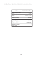
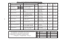
Revision Control Table
No,
Date of Revision
Revision Code
Description of Revision
1
July 14, 1997
First Edition
First Edition (Original)
2
October 13, 1997
Revision “A”
First revision made and issued as Rev.”A”
3
February 27, 1998
Revision “B”
First revision made and issued as Rev.”B”
FCC Notice
WARNING
This equipment has been tested and found to comply with the limits for a Class B digital
device pursuant to Part 15 of FCC Rules. These limits are specified to provide the
reasonable protection against harmful interference in a residential installation.
Since this equipment generates, uses, and radiates the radio frequency, it may cause
harmful interference to the radio communications if not installed or used in accordance
with the instructions set out hereunder. However, there is no guarantee that such
interference will not occur in a particular installation.
If this equipment causes harmful interference to the radio or television reception, which
can be checked and confirmed by powering the equipment off and on, the users are
encouraged to correct the interference by taking one or more of the following countermeasures:
1 . Reorient or relocate the receiving antenna.
2 . Give more clearance between the equipment and receiver.
3 . Connect the equipment into the outlet of other circuit which is different from the
one being used for the receiver.
4 . Consult the dealer or experienced radio/television technician for help.
Canadian Compliance
This digital apparatus does not exceed the Class B limits for radio noise emissions from
digital apparatus set out in the Radio Interference Regulations of the Canadian
Department of Communications.
"Le presnt appareil numerique n'emet pas de bruits radioelectriques depassant les limites applicables aux appareils numeriques (de la Class B) prescrites dans le Reglement
sur le brouillage radioelectrique edicte par le ministere des Communications du
Canada."
(i)
Product Safety
Laser Product
SL1 is certified as a Class 1 laser product and complies with DHHS Laser-Radiation
Standards, 21 CFR Chapter 1, Subchapter J.
Caution
Use of controls, adjustments or performances of procedures other than those specified
in this Manual may result in hazardous radiation exposure.
Ozone Gas
Caution
SL1 is provided with the ozone filter in order to reduce exhausted ozone in compliance
with Product Safety Standards. Ozone filter must be replaced with new filter yearly,
otherwise, it may cause strong odor which will likely have ill effects to bronchial tubes.
Therefore, this periodical replacement with new filter must be strictly respected.
Documentation Disclaimer
HITACHI, LTD. MAKES NO REPRESENTATION OR WARRANTIES OF ANY KIND
WHATSOEVER WITH RESPECT TO THE CONTENTS HEREOF AND SPECIFICALLY
DISCLAIMS ANY IMPLIED WARRANTIES OF MERCHANTABILITY OR FITNESS FOR
ANY PARTICULAR PURPOSE.
(ii)
SAFETY INSTRUCTIONS
1. Safety Instructions
1.1 Safety Principle
(1). Before starting your operation, read this Manual thoroughly. Especially, read
the safety instructions of this section carefully and understand the contents.
(2). Perform all the operations by following the procedures described in this
Manual. Follow all the cautions and warnings set out in the procedures and
on safety labels affixed on the machine. Failure to do so may result in the
human injuries or equipment damages.
(3). Perform only the procedures explained in this Manual. Refrain from opening
or touching any portions that are not related with your operation.
(4). Repair and replacement of parts should be performed by trained and qualified
persons only. Operator should not attempt to do such repair or replacement
works.
(5). It must be appreciated that above-mentioned cautions and warnings do not
cover everything, because it is impossible to guess or evaluate all the
circumstances beforehand.
1.2 Special Safety Information
(1). Introductory Information
The cautions and warnings are made clear by following the "Safety Alert
Symbol" or "Signal Words" such as DANGER, WARNING and CAUTION.
1 . Safety Alert Symbol
This is the safety alert symbol. When you find this symbol placed on
your equipments or marked in this Manual, be alert for the potential of
human injuries.
Follow the recommended precautions and safety
operation practices.
(iii)
(1). Introductory Information (..... continue)
2 . Understanding Signal Words
DANGER is used to indicate the presence of a hazard which will cause
severe human injuries or fatal accident if the warning is ignored.
WARNING is used to indicate the presence of a hazard or unsafe practices
which may cause severe human injuries or fatal accident if the warning is
ignored.
CAUTION is used to indicate the presence of a hazard or unsafe practices
which may cause minor human injuries if the warning is ignored.
CAUTION also calls attention to safety messages in this Manual.
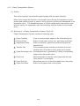
3 . Follow Safety Instructions
Carefully read all the safety messages set out in this Manual and also in the
safety signs placed on your equipments. In this Manual, the safety
instructions (safety alert symbols and signal words) are bracketed by
rectangular enclosure to call for attention. Keep the safety signs in good
condition without missing or damage. Replace the safety signs if smeared
or damaged. Learn how to operate the equipment and how to use the
control properly. Do not let anyone operate without acknowledging the
instructions. Keep the equipments in proper working condition.
Unauthorized modification to equipments may impair the function & safety,
and affect the life of equipments.
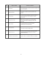
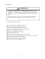
Listed below is the various kind of "WARNING" contained in this Manual.
WARNING
HAZARDOUS VOLTAGE
It may cause serious injuries or fatal accidents. Voltage is now applied
from the power supply of printer. There is the danger of electrical shock if
you touch the active area inside the printer.
Make sure to turn the power supply switch OFF and pull out the plug from
the outlet before starting maintenance work to printer.
(iv)
3 . Follow Safety Instructions (.... continue)
WARNING
HARMFUL OZONE GAS
Inhalation of excessive amount of ozone gas may adversely affect the
respiratory organs.
Ozone Filter is provided to this printer to reduce the exhausted ozone.
This filter must be replaced with new filter periodically in accordance with
the Manual attached to this printer.
Listed below are the various kinds of "CAUTION" contained in this Manual.
HOT SURFACE
Can cause a burn.
Fusing Unit is approx.160 C hot , so that perimeter is also very hot.
When you need to change the cleaning pad or remove jammed papers,
wait about 20 minutes after opening up the paper exit unit and confirm the
unit to be well cooled down.
CAUTION
ROTATING PARTS
Be cautioned about the potential danger of various rollers to get your
fingers or hand caught into the machine and cause serious injuries.
Note that the exit roller ejecting printed papers is rotating while printing.
Be careful not to get your hairs, fingers, hands, and sleeve or necktie
caught in the machine while operating the machine.
(v)
3 . Follow Safety Instructions (.... continue)
CAUTION
HAZARDOUS POWDER
Toner is fine powder to cause powder explosion if dumped into the fire.
Strictly refrain from dumping toner into the fire for disposal.
CAUTION
HAZARDOUS POWDER
Toner is fine powder to cause troubles to eyes and respiratory organs if
inhaled.
Handle carefully toner cartridge, waste toner pack and developing unit not
to spread the toner.
CAUTION
POWER CORDS & PLUGS
This printer is equipped with 3-wire power cords and 3-pronged plugs
(bi-polar plug with grounding) for the user's safety.
Use these power cords in conjunction with properly grounded electrical
receptacles to avoid an electrical shock.
CAUTION
SAFETY INTERLOCK
Cover and Paper Delivery Unit of this printer have electrical safety interlocks
to turn the power off whenever they are opened. Do not attempt to
circumvent these safety interlocks.
(vi)
CONTENTS
PREFACE and SAFETY INSTRUCTIONS
1. OUTLINE OF PRODUCT
2. SPECIFICATIONS OF PRODUCT
3. INSTALLATION
4. STRUCTURE OF EACH COMPONENT SYSTEMS
5. PERIODIC MAINTENANCE
6. OPERATION AND ADJUSTMENT OF OPERATOR PANEL
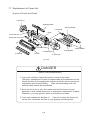
7. REPLACEMENT OF MAINTENANCE PARTS
8. TROBLESHOOTING
9. PARTS LIST
1. Outline of Product . . . . . . . . . . . . . . . . . . . . . . . . . . . . .1-1
1.1 Name & Function of Each Parts . . . . . . . . . . . . . . . .1-1
1.2 Internal Structure . . . . . . . . . . . . . . . . . . . . . . . . . . .1-3
1.3 Description of Operator Panel . . . . . . . . . . . . . . . . .1-4
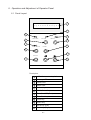
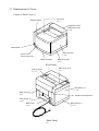
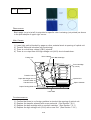
1. Outline of Product
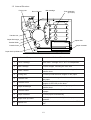
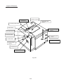
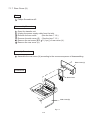
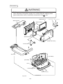
1.1 Name & Function of Each Parts
Top Cover
Operator Panel
Paper Exit Cover
Main Switch
Front Cover
Paper Cassette
[Front Face]
Paper Exit Unit
Interface Connector Box
Back Cover(L)
AC Input Inlet
[Back Face]
1-1
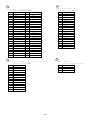
No.
Name of Parts
Outline of Functions
1
Top Cover
To act as an upper enclosure and also a paper tray
for printed papers.
2
Operator Panel
To display a status of printer operation and
motion.
3
Front Cover
To act as a front enclosure, and to be opened
when replacing a toner cartridge or waste
toner pack.
4
Paper Exit Cover
To exit a printed paper onto a top cover,
acting also as paper tray for printed paper.
To be opened when replacing an OPC belt
cartridge.
5
Main Switch
To operate power-on and off of printer.
(Pushing for On/Off operation)
6
AC Input Inlet
To connect a power supply cable.
7
Back Cover (L)
To act as a rear enclosure, and to be opened
when clearing an internal jam or doing a
maintenance work.
8
Interface Connector Box
Space where a controller PWB to be installed.
1-2
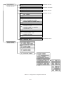
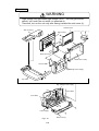
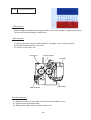
1.2 Internal Structure
Fusing Unit
Belt Cartridge
Drum Cleaner
Toner Cartridge
@(K,Y,M,C)
K
Y
M
Transfer Unit
C
Paper Discharger
Optical Unit
Transfer Roller
Transfer Drum
Paper Cassette
Paper Pick Up Roller
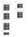
No.
Name of Components
Outline of Functions
1
Toner Cartridge
To contain the toners (K, Y, M, C) for developing.
Each toner cartridge of K,Y, M, C is independent.
2
Belt Cartridge
To form images, including the OPC belt.
3
Drum Cleaner
To clean and collect waste toner adhering to the
transfer drum.
4
Fusing Unit
To fuse by heat the toner images on the paper.
5
Transfer Unit
6
Transfer Drum
7
Paper Discharger
8
Transfer Roller
To transfer toner images from the transfer drum to
the paper.
To form color images, maintaining the toner
images of OPC belt on the drum.
To emit the corona for separating a paper from
transfer drum.
To transfer the toner image of transfer drum to
a paper.
9
Paper Cassette
To feed papers automatically.
10
Paper Pick Up Roller
11
Optical Unit
To feed papers automatically from the paper
cassette.
To generate a laser beam and scan over the OPC
belt.
1-3
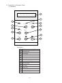
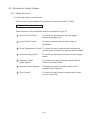
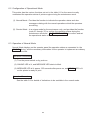
1.3 Description of Operator Panel
(1) Standard
‘ a b c d e f g h i j k l m n o
P Q R S T U V W X O P Q R S T U
1
3
2
4
MESSAGE
ONLINE
MEDIA
5
6
7
FREE SIZE
9
CLEAR
8
11
SELECT
10
12
Description:
1
LCD:16 characters by 2 lines
2
Message LED
3
Online LED
4
Media LED
5
Online Key
6
Media Select Key
7
Free Size LED (Red)
8
Free Size Key
9
Clear Key
10
Select Key
11
Scroll Key (Left)
12
Scroll Key (Right)
1-4
2. Specifications of Product . . . . . . . . . . . . . . . . . . . . . . . .2-1
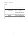
2.1 Rating . . . . . . . . . . . . . . . . . . . . . . . . . . . . . . . . . . .2-1
2.2 General Specification . . . . . . . . . . . . . . . . . . . . . . .2-2
2.3 Environmental Condition . . . . . . . . . . . . . . . . . . . . .2-5
2. Specifications of Product
2.1 Rating
WARNING
Use the power supply cord provided as an accessory, or the similar cord
complying with following specification (3-wire power cord with grounding).
Use of the "out of specification" cord may result in the electric shock.
Name of Model
SL1-U
SL1-E
SL1-J
Voltage (V) Frequency (Hz) Input Current (A)
120
50/60
8
220 - 240
50/60
4
100
50/60
10
Power Cord (Piece)
1 (Standard)
Not included. *1
1 (Standard)
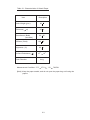
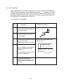
*1: As to SL1-E, customers are requested to purchase and use the power
cord complying with the following specifications.
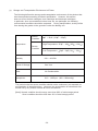
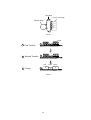
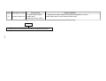
Figure Name of Model
Rating
A
H05VV-F3G0.75 250VAC, 6A
B
H05VV-F3-0.75
250VAC, 6A
Approval Agency
Applicable Area
VDE, OVE, SEMKO, CEBEC,
Europe
NEMKO, DEMKO, FIMKO
(Continent)
BS
UK
Rating label of SL1-U
Rating label of SL1-E
Fig.A: Power Cord for Europe
2.5m
Fig.A: Power Cord for Europe
2.5m
2-1
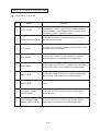
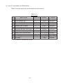
2.2 General Specification
No.
Item
Description
1
Printing Method
Semiconductor Laser and Electrophotography
2
Print Speed
a). Monochrome
b). 2 (two) Color
c). 3 (three) Color
d). 4 (four) Color
Cassette Feed and Continuous Print:
a). 16 sheets per minutes (Letter size)
b). 8 sheets per minutes (Letter size)
c). 5.3 sheets per minutes (Letter size)
d). 4 sheets per minutes (Letter size)
3
Warming-Up Time
210 seconds (max.), 180 seconds (Normal)
4
Resolution
600dpi
5
Feeding Method
Cassette Feed
6
Cassette Capacity
Ordinary Paper: 250 sheets, OHP: 50 sheets
Envelope: 30 envelopes, Post Card: 50 cards
7
Printable Media
Letter, Legal, Executive (A4, B5), OHP, Label,
SPHINX
8
Paper Exit System
Face Down, 250 sheets (capacity)
9
External Dimension
500 (W)
19.7 (W)
10
Weight of Printer
490 (D)
19.3 (D)
388 (H) (unit: mm)
15.3 (H) (unit: inch)
Approximately 36kg (79 pounds)
2-2
Table 2-1: Characteristics of Hitachi Paper
Item
Description
Basis Weight (g/m2)
82 5
Thickness (
95 6
m)
Smoothness (Bekk)
(seconds)
90 20
Stiffness (Clark)
100 15
Brightness (%)
85 2
Surface Resistance (
)
1010
Grain Direction
Measurement Condition: 17.5
1011
Long
27.0 C , 50
70%RH
[Note]: Keep the paper sealed, and do not open the paper bag until using the
papers.
2-3
Table 2-2: Characteristics of Hitachi Recommend Paper, OHP Sheet, and Label
Media
Item
Basis Weight (g/m2)
Paper
Xerox 4024
Paper Hammermill
Laserprint (white)
Label
Avery 5260
OHP Sheet
SPHINX
Auto Fil #1914
75 4
90 4
163 7
142 4
102 6
105 6
184 7
110 6
35 4
120 20
20 6
500 100
Stiffness (Clark)
100 15
90 15
65 15
56 15
70
20
Surface Resistance
109 ( )
10
1000
1000
1
100
Thickness (
/m)
Smoothness(Bekk)
L*
CIE
LAB
100
10
100
1
100
94 2
94 2
93 2
0.4 1
0.5 1
0.2 1
10
10
90 4
125 10
22 10
80%
a*
(Transmittance)
L*a*b*
b*
1.6 1
2.2 1
4.5 1
Brightness (%)
80 2
85 2
77 3
Grain Direction
Long
Long
Measurement Condition: 17.5
27.0 C , 50
Long
: Printed Side
: Back Side
2-4
70%RH
82
5
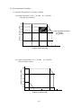
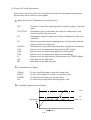
2.3 Environmental Condition
(1). Ambient Temperature / Humidity / Altitude:
(a). Under Operation: 10.0
32.5 C , 20
(See the figure below.)
80%RH
Ambien
Humidity (%RH)
80
70
60
Recommended Condition;
17.5 27 C
50 70%RH
50
40
20
0
10
17.5 20
27 30
Ambient Temperature ( C)
32.5 40
(b). Under No Operation: 5.0 ~ 35.0 C , 10 ~ 80%RH
(See the figure below.)
Ambient Humidity (%RH)
80
60
40
30
20
10
0
5
10
20
Ambient Temperature( C )
2-5
30
35
40
(c). Storage and Transportation Environment of Printer
The following defines the storage and transportation environment of the printers that
have been packed according to Hitachi specification. However, this section
does not cover the belt cartridges, toner cartridges and developer cartridges.
In particular, since consumables such as toner etc. are packaged, the following
environmental conditions should be respected. During transportation, strictly refrain
from leaving the goods on the ground or under the blazing sun.
Normal
Condition
Temperature
0 C ~ 35 C (32 F ~ 95 F)
High Temperature: 35 C ~ 40 C (95 F ~104 F)
Severe
Condition
Low Temperature: 10 C ~ 0 C (14 F ~ 32 F)
Humidity
10% ~ 90%RH
Period of Storage
One Year
Other
No Condensation
Atmosphere
613 ~ 1,067hpa (460 ~ 800mmHg)
The period under the severe condition should not be continuous, but assumed as
accumulation of intermittent time. However, the accumulation of intermittent time
should not by any means exceed 48 hours at maximum.
[Note]: Normal condition should occupy more than 90% of total storage period.
Sever condition should be less than 10% of total storage period.
2-6
3. Installation . . . . . . . . . . . . . . . . . . . . . . . . . . . . . . . . . . .3-1
3.1 Conditions for Installation . . . . . . . . . . . . . . . . . . . .3-1
3.2 Unpacking . . . . . . . . . . . . . . . . . . . . . . . . . . . . . . . .3-2
3.2.1 Unpacking of Printer . . . . . . . . . . . . . . . . . . . . .3-2
3.2.2 Unpacking of Starter Kit . . . . . . . . . . . . . . . . . .3-4
3.3 Installation Work . . . . . . . . . . . . . . . . . . . . . . . . . . .3-5
3.3.1 Installation of toner cartridge to the printer . . . . .3-5
3.3.2 Installation of OPC Belt Cartridge . . . . . . . . . . .3-6
3.3.3 Installation of Cleaning Roller and Oil Bottle . . .3-7
3.3.4 Test Run and Test Print . . . . . . . . . . . . . . . . . . .3-8
Installation
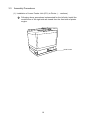
3.1 Conditions for Installation
Laser beam printer is likely influenced by the environment of set-up location.
IF Printer was set up at the inappropriate location, the printer may not perform
the characteristic functions as expected. Therefore, the following factors
should be taken into consideration prior to deciding where to set.
(1). Environmental Conditions
Printer should not be set up at the locations referred to by the following
items (a) through (d) specifying the inappropriate locations for set-up.
(a). Likely to receive the direct sunbeam or similar light.
(For example, window side)
(b). Likely to cause the big difference in temperature and humidity between
the maximum and minimum level.
(Normal operation environment is
within 10 C ~ 35 C , 20 ~ 80%RH and without any condensation.)
(c). Likely to receive cold wind from air-conditioner or worm wind from
heater, or to receive direct radiant heat.
(d). Likely to cause much dust or have corrosive gas like ammonia.
(e). Users to select the location of good ventilation and set a printer on the
flat surface.
(f). Users to check the maximum tilt of set-up location to be within 1 .
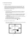
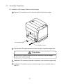
(2). Basic Layout of Printer Set-Up Location
Fig.3-1 shows the basic layout of printer set-up location suitable for the
smooth operation and maintenance of printer.
10cm(4")
40cm(16")
70cm(28")
Front Side
Paper Exit Side
3.
10cm(4")
[Fig.3-1]
3-1
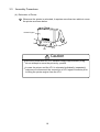
3.2 Unpacking
WARNING
•The package containing a printer weighs approximately 40kg, so that it is
too heavy for one person to carry. It needs more than two adults to move
the printer.
Since this printer is a precision machine, ensure to carry it
slowly with good care so that no impact shall be given to the printer while
moving.
•Do not attempt to hold a printer as covered by vinyl sheet, because it is
slippery and results in damage and injury if dropped from your hand.
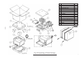
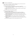
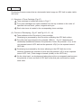
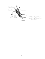
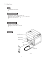
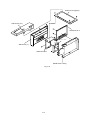
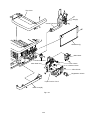
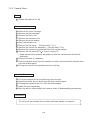
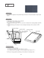
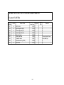
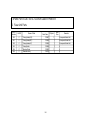
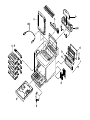
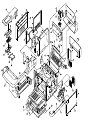
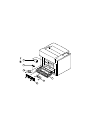
3-2-1 Unpacking of Printer (Fig.3-2)
1 . Cut the bands (2 pcs.) binding the package.
2 . Remove the plastic joints 17 (4 locations).
3 . Remove the tape 18 binding the top of package.
4 . Open up the top of package to take the starter kit out.
5 . Lift the outer box 1 up for removal.
6 . Remove the top partition packing 3 .
7 . Take the power cable out.
8 . Open up the vinyl sheet 5 covering the printer body.
9 . Lift up the printer body with another person's help, and lay it on the floor.
10 . Set up the printer on the suitable location.
11 . Remove the tape 8 fixing the paper cassette.
12 . Remove the protective tape 9 (1 location).
3-2
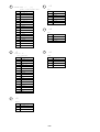
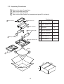
No.
1
2
3
4
5
6
7
8
9
10
11
12
13
14
15
16
17
18
NANE OF PARTS
Q’TY
OUTER BOX
1
BASE
1
UPPER PACKING
1
SILICA GEL (EN)
1
POLYETHYLENE BAG (EN)
1
POLYETHYLENE BAG (ST)
1
ST KIT TAPE
4
TAPE
1
PR TAPE
1
STARTER KIT PACKING (U)
1
STARTER KIT PACKING (L)
1
SILICA GEL (ST)
2
POLYETHYLENE BAG (T)
4
POLYETHYLENE BAG (CL)
1
POLYETHYLENE BAG (OIL)
1
POLYETHYLENE BAG (OPC)
1
JOINT
4
OUTER BOX TAPE
1
Band
o
3-3
X ^ [ ^ L b g
14
9
d „ P [ u
8
Fig.3-2:Unpacking of Printer Package
x [ X
h
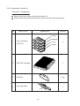
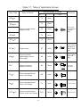
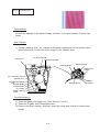
3-2-2 Unpacking of Starter Kit
Procedure of Unpacking
1 . Open up the vinyl sheet covering the starter kit.
2 . Confirm all of the following kits to be inside the starter kit's packing box.
No.
Name of Kit
Appearance
Quantity
Y (Yellow)
M (Magenta)
1
Toner Cartridge
(Y.M.C.K)
2
OPC Belt Cartridge
3
Oil Bottle
C (Cyan)
4
K (Black)
1
1 set.
Cleaning Roller
4
Cleaning Roller
1
Spuit
3-4
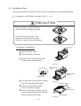
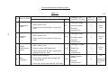
3.3 Installation Work
Install the unit parts of starter kit to the printer according to the following procedures:
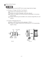
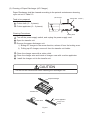
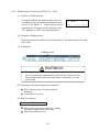
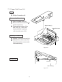
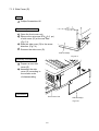
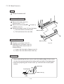
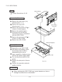
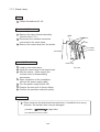
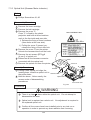
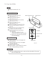
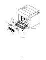
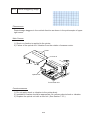
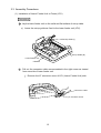
3.3.1 Installation of OPC Belt Cartridge: (Fig.3-3 ~ 3-6)
PRECAUTION
Do not directly touch the OPC belt
surface with bare hands or gloves.
If OPC belt is exposed for more
than two minutes under the light
of 800 lux, the belt may be defective.
Paper Exit Cover
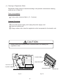
Procedures of Installation
1 . Open the front cover.
2 . Open the paper exit cover.
3 . Erect the lock lever BC provided
at both sides (left and right).
Front Cover
[Fig.3-3]
Guide
Lock Lever BC
(Left)
Lock Lever BC
(Right)
Lock Lever BC
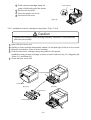
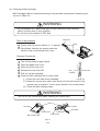
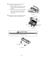
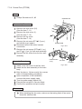
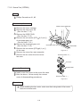
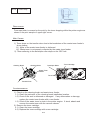
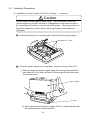
4 . Pull and remove the tension release
pins of both sides (left & right).
5 . Remove the protective sheet
from a new belt cartridge.
6 . Push the new belt cartridge into the
printer, along the guide of lock lever
BC provided at both sides.
[Fig.3-4]
Protective Sheet
Tension
Release Pins
Belt Cartridge
[Fig.3-5]
3-5
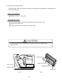
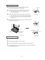
6 . Push new belt cartridge along the
guide of both sides into the printer.
7 . Set the lock lever BC.
8 . Close the paper exit cover.
9 . Close the front cover.
Lock Lever BC
Guide
[Fig.3-6]
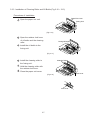
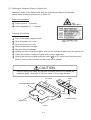
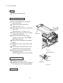
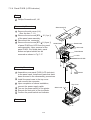
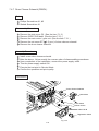
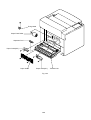
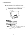
3.3.2 Installation of toner cartridge to the printer: (Fig.3-7~3-9)
Caution
Refrain from holding a toner cartridge vertically, otherwise, it may adversely
affect the print quality.
1.
2.
3.
4.
Open the front cover unit.
Holding a toner cartridge horizontally, shake it to left and right for three to four times.
Remove a protective cover of toner cartridge.
Push the new toner cartridge along the guide into the printer.
Installation order of toner cartridge in terms of color shall be Cyan (C), Magenta (M),
Yellow (Y), and Black (K).
5 . Close the front cover unit.
Toner Cartridge
Front Cover
[Fig.3-7]
[Fig.3-8]
Protect Cover
Toner Cartridge
[Fig.3-9]
3-6
K
Y
M
C
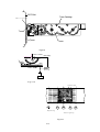
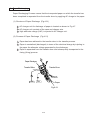
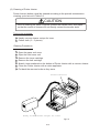
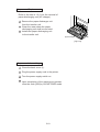
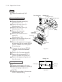
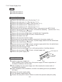
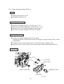
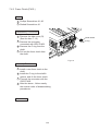
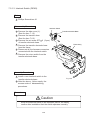
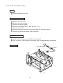
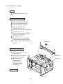
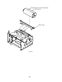
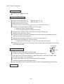
3.3.3 Installation of Cleaning Roller and Oil Bottle:(Fig.3-10 ~ 3-13)
Procedures of Installation
Paper Exit Cover
1 . Open the paper exit unit.
Fusing Unit
[Fig.3-10]
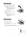
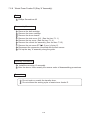
2 . Open the retainer lock lever
of oil bottle and the cleaning
roller.
3 . Install the oil bottle to the
fusing unit.
Fusing Oil Bottle
[Fig.3-11]
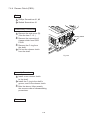
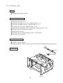
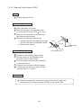
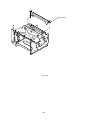
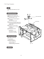
4 . Install the cleaning roller to
the fusing unit.
5 . Hold the cleaning roller with
the retainer lock lever.
6 . Close the paper exit cover.
Cleaning Roller
Lock Lever
[Fig.3-12]
Lock Lever
3-7
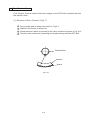
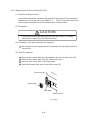
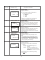
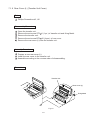
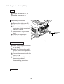
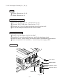
3.3.4 Test Run & Test Print
(1). Power-On & Off
( i ). Power-On:
There is
mark on the power supply switch located on the side panel of the
printer.
represents the power supply switch with push-on/push-off function.
1
Prior to connecting a power
cable, confirm that the push
button top of power supply
switch located at the lower
left front of printer projects
from the cover surface.
This means that the printer is in
the power-off status.
2
Connect a connector of power
supply cable to the printer.
3
Insert a plug of the power
supply cable to the inlet.
4
Pressing the scroll keys (left &
right) and Free Size key, push
the push button top of power
supply switch. Next, press the
ONLINE key. Then, the display
of operator panel turns to be the
status of (a), and "MESSAGE"
LED lamp starts to blink.
This blinking means
that the printer is in the
warming-up process.
5
"MESSAGE" LED lamp
changes to be lit within 210
seconds at max., when screen
(b) appears on the operator
panel display.
3-8
Power Supply Switch
(a). Indication at Warming-UP
01
WAIT
U:LT
MESSAGE
FREE SIZE
/UPP
L:[
ONLINE
]
[
MEDIA
CLEAR
SELECT
(a). Indication at Warming-UP
00
U:LT
READY
/UPP
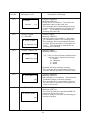
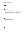
(ii). Power-Off:
1
Push the push button top of
power supply switch in order to
shut off the power supply to the
printer.
Power Supply Switch
(This switch is push-on/push-off
type. )
2
Unplug the power supply cord
from the inlet.
(iii). Precaution while power-on & off operation:
PRECAUTION
Prior to unplugging the power supply cord, confirm that the main switch
located on the side panel of printer is set to the Push-Off.
Strictly refrain from powering off or unplugging while the printer is
performing the printing operation.
When resetting the power-on, make sure to wait at least 5 seconds after
powering off.
3-9
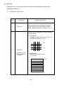
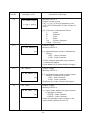
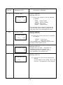
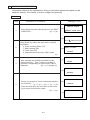
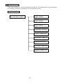
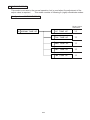
(2). Test Print
After power-on, confirm the normal printing by test printing according to the
following procedures:
( i ). Procedure of Test Print
Step
1
Operation
Power-On
Details of Operation
Upon completion of the warming-up process,
printer is ready to print and waits for PRINT
signal. [See the power-on in Section 4.1-(1).]
Printer has the following built-in print patterns
for test printing.
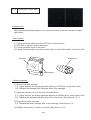
1). Grid Pattern :
Available in mono color print of Y, M, C, K,
and two color print of R, G, B.
GRID
2
Test Print
See Item (ii) "Test
Print Procedures"
for details.
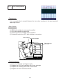
2). Stripe Pattern:
Available in color print of Y, M,
C, K, R, G, B.
STRIPE
3-10
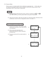
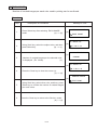
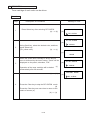
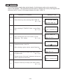
(ii) Test Print Procedures
Implement the test print according to the following procedures upon completion of the
warming-up process.
Procedure
Indication of Operator Panel
1 Warming-up process is
completed.
00
READY
U:[
] L: [
[
]
[
]
a)
]
2 Press ONLINE key so that
display changes from screen
(a) to (b).
SERVICE MODE
b)
TEST PRINT / NEXT
3 Press SELECT key so that
display changes from screen
(b) to (c).
c)
31 TEST PRINT
GRID / STRIPE
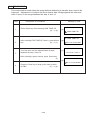
4 Select GRID or STRIPE
5
6
7
8
9
10
pattern with scroll key.
( GRID to be selected.)
Press SELECT key so that
display changes from screen
(c) to (d).
Select the color to be printed
with scroll key.
( R to be selected.)
Press SELECT key so that
display changes from screen
(d) to (e).
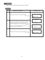
Warming-up starts, and
continuous print will be
automatically carried out
upon completion of the
warming-up.
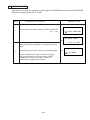
Printing operation will be
suspended by pressing
CLEAR key, and display
changes from screen (e)
to (f).
Printer will be returned to
ONLINE mode by pressing
ONLINE key, and display
changes from screen (f) to
(g).
d)
31 GRID PRINT
Y/M/C/K/R/G/B
e)
31 GRID PRINT (R)
U:[
] L: [
]
[
]
Continuous Print
31 GRID PRINT
f)
Y/M/C/K/R/G/B
01
WAIT
U:[
] L: [
[
]
[
]
g)
3-11
]
(iii). Selection of Media
Pressing the media select key on the operator panel, select the suitable process
for the media to be used.
When the media select key is pressed, the media lamp changes as follows:
Condition of Media Lamp
Selected Media
Lit Out
Ordinary Paper
Blinking
Stock Paper, Label
Lit
OHP Sheet
(iv). Operator Call
When "Operator Call" is indicated on the operator panel, see "Operator Call"
column in Sub-section 8.1- (1), and take necessary actions accordingly.
3-12
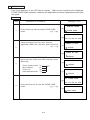
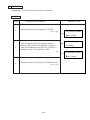
(3). On-Line Print
Upon confirmation of normal printing by the test print mode, proceed with the
On-Line Print according to the following procedures.
However, since this
Operator Manual does not refer to the connection method of Interface, or the
operating method of Host side, make sure to read the operation procedure of
the Host prior to starting the On-Line Print.
( i ). Procedure of Operation
Step
Operation
Details of Operation
1
Connect the interface cable to
the host machine.
2
Push the push button top of
power supply.
3
4
Confirm that the printer is set to Confirm what is indicated on the
operator panel.
the On-Line mode.
(Display as per right-hand figure.)
Upon completion of warming-up
process, "MESSAGE" LED
lamp is lit.
This warming-up process is 210
seconds at maximum.
5
Printer start the printing
operation upon receipt of the
PRINT signal transmitted from
the Host.
3-13
00
READY
U:[
]
MESSAGE
L:[
ONLINE
/UPP
] [
]
MEDIA
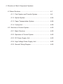
4. Structure of Each Component Systems
4.1 Basic Structure..........................................................................4-1
4.1.1 Print System and Transfer System ................................4-6
4.1.2 Optical System...............................................................4-24
4.1.3 Paper Transportation System ........................................4-26
4.1.4 Fusing Unit ....................................................................4-28
4.2 Structure of Control System.....................................................4-30
4.2.1 Basic Structure ..............................................................4-30
4.2.2 Operation of Control System ........................................4-40
4.2.3 DC Power Supply Unit...................................................4-50
4.2.4 High Voltage Power Supply Unit....................................4-53
4.2.5 General Wiring Diagram ................................................4-55
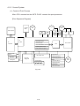
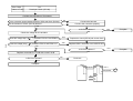
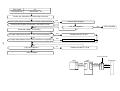
4. Structure of Each Component Systems
4.1 Basic Structure
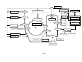
(1). Mechanical & Electrical Structures
This laser beam color printer (hereinafter called "Printer") consists of the five
engineering systems such as Print, Transfer, Optical, Paper Transport, and
Control System. Printer runs a color printing through the interactive operations
of above five systems as shown in Fig. 4-1.
1 . Print System
Print system consisting of the following 6 (six) functional parts located around
OPC Belt forms a toner image on the OPC Belt.
•Charger Part
•Exposure Part
•Development Part
•First Transfer Part
•Discharger Part
•Cleaner Part
2 . Optical System
Optical system consisting of the following 2 (two) functional parts forms
electrostatic latent images on the OPC Belt by scanning a laser beam.
•Optical Unit
•Scanner Motor(SCM)
3 . Transfer System
Transfer system consisting of the following 3 (three) functional parts transfers
to the transported paper the toner image formed on the transfer drum.
•Transfer Drum
•Second Transfer Part
•Drum Cleaner Part
4 . Paper Transport System
Paper transport system consisting of the following 5 (five) functional parts
picks up a paper from the paper cassette, separates the transported paper from
the transfer drum, and exits it from the printer body after fusing the toner image
on the transported paper.
•Paper Cassette
•Transport Part
•Paper Discharger Part
•Fuser Part
•Paper Exit Part
4-1
Main Motor
MM
Developer Motor
Paper Exit Unit
Paper Exit
I/F Controller
Drum Cleaner Unit
DM
Fuser Unit
Toner
Cartridge
Fix
OPC Belt
Drum Cleaning
Operation
Development
Transfer Unit
4-2
AC Discharger Unit
Transfer Roller
Paper Discharger
Transfer Drum
MCTL
I/F Control
K
Sequence Control
Y
M
Laser Control
C
First Transfer
Second Transfer
Optical Unit
Exposure
LD
Discharge
Laser Diode
Resistration Roller
Charge
Transport Roller
Erase Lamp
DC Charger
Cleaning
Paper Feed
Paper Cassette
Fig4-1
SCM
Scaner Moter
5 . Control System
Control system consisting of the following 4 (four) control parts runs the printer by
processing the interface signals transmitted from the Host and each systems such
as the print, transfer, optical, transport system.
•Sequence Control
•Laser Control
•Fusing Temperature Control
•Interface Control
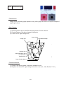
(2). Basic Mechanism of Color Printing
1 . Principle of Color Printing
Color printing is made through the subtractive process by combining the three
primary colors, yellow, magenta, and cyan. Fig.4-2 shows the three primary
colors and subtractive process:
C
GR
BL
BK
M
Y
R
Y: Yellow
M: Magenta
C: Cyan
R: Red
G: Green
B: Blue
K: Black
Fig.4-2
2 . Basic Process of Color Printing
(a). Printer has the Toner Cartridge of each colors, yellow, magenta, cyan and black as
shown in Fig.4-3.
(b). Toner image developed with the primary colors is transferred to the transfer drum
for the color combination as shown in Fig.4-4-a.
(c). Toner image formed on the transfer drum is transferred to a transported paper as
shown in Fig.4-4-b.
(d). Toner on the paper is fused by the thermal fuser unit to fix the toner image on the
paper as shown in Fig.4-4-c.
Summarizing the above processes, a toner color layer is formed on the transported
paper, and subsequently, the color image is made through the subtractive process.
4-3
OPC Belt
Toner Cartridge
Transfer Drum
K
Y
M
C
Fig4-3
Toner
MMM
CC C
Y Y
Y
Y
Y
Y CC
a . First Transfer
Transfer Drum
b . Second Transfer
b
Y Y Y
Y Y Y
MMM C C C CC
Paper
Red
C . Fusing
C
R
Cyan
Green
C
G
Paper
Fig4-4
4-4
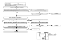
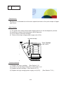
(3). Structure of OPC Belt
OPC belt consists of the surface layer having a photoconductor (OPC) of organic
material, the inner layer of an insulator material (PET), and the aluminum deposit
layer in between. OPC belt is located as shown in Fig.4-5 as a main part of the
print system.
Belt Cartridge
Toner Cartridge
OPC Belt
K
Transfer Drum
Y
M
C
Optical Unit
Fig4-5
Electrode
Photoconductor(OPC)
Aluminum Deposit Layer
Insulator Material
Fig4-6
4-5
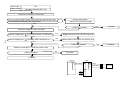
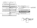
4.1.1 Print System and Transfer System
Fig.4-7 shows the basic structures of the print system having OPC belt as a main
part, and the transfer system having the transfer drum. Color print is made by
actuating the each processes in the print system and transfer system.
1 @ @ C
@ hargimg
2 @ @ E
@ xposing
KCMY
6 @ OPC Belt Cleaning
3 @ @ @
Developing
KCMY
5 @ @ @
Belt Discharge
Print System
KCMY
OPC Belt
4 Transfer Drum(First Transfer)
Transfer Drum K C M Y
Transfer System
7 @Second Transfer(Paper)
8 @ @Paper Dischanging
10 @ @ @
Fusing
Transport System
11 @ @ @
Paper Exit
Fig.4-7: Basic Structure of Print System
4-6
9 @ Transfer Drum Cleaning
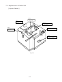
(
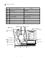
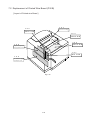
) Structure of Printer
No.
1
2
3
4
5
6
7
8
9
10
11
12
Name of Component Part
Charger
Optical Unit
Toner Cartridge
Belt Cartridge
Transfer Drum
Belt Discharger Erase Lamp
Cleaning Blade
Transfer Roller
Paper Discharger
Drum Cleaner
Fuser Unit
Paper Exit Unit
10
Drum Cleaner
Process
Charging
Exposing
Developing
Receiving of Image
Transferring of Image
Discharging of Belt
Cleaning of Belt
Transferring
Discharging of Paper
Cleaning of Drum
Fusing
Exiting of Paper
4 Belt Cartridge
11 Fusing Unit
3
Toner Cartridge
(K,Y,M,C)
12 Paper Exit Unit
K
Y
M
Transfer Unit
C
9 Paper Discharger
2 Optical Unit
8 Transfer Roller
Paper Cassette
5 Transfer Drum
Paper Pick Up Roller
6 Erase Lamp
7 Cleaning Blade
4-7
1 Charger
( ) Basic Structure of Printing System
Toner image is formed through the potential of OPC belt varying in each process of the
charger, exposure, development, transfer and cleaning.
1 . Process of Print System (See Fig.4-8-a)
(i ). OPC belt is biased to the voltage -CBV(V) by the power supply CBV.
(ii). Negative high voltage is applied to the charger unit by the power supply CHV, and
corona is generated as the result.
(iii). Developer Roller of the toner cartridge is biased to -DBV(V) by the power supply
DBV.
(iv). Frame potential of the transfer drum is GND.
2 . Variation of OPC Belt's Potential (See Fig.4-8-b)
(i ). OPC belt is biased to -CBV(V).
(ii). OPC belt's surface is evenly charged to V0(V) in the process of charging.
(iii). Potential of the exposure part is discharged till -VR(V) as exposed to the laser
beam in the process of exposing, and an electrostatic latent image is formed on
the OPC belt as the result.
(iv). Negatively charged toner is moved to OPC belt in the development process due to
difference of potential between -VR(V) and -DBV(V), and the visible image is
formed as the result.
(v). Negatively charged toner on the OPC belt is moved to the transfer drum in the
transfer process because the potential GND of transfer drum is greater than -VR(V)
of OPC belt.
(vi). OPC belt is discharged by the erase lamp radiating the OPC belt.
4-8
Cleaning UNIT
FCBV
Fuser Unit
Toner
OPC Belt
Toner Cartridge
K
Develop
Paper Discharger
Y
Transfer Drum
M
ACHV
DBV
C
Transfer Roller
CBV
Optical Unit
THV (+)
THV ( - )
Cleaning
Paper
Erase Lamp
Brade
Charger
CHV
ZDV
Fig.4-8-a: Basic Structure of Print System
4-9
Po
2
1
Process
3
5
4
Transfer Drum
GND
OV
Toner
- CBV
- VR
Toner
OPC Belt
DBV
Dev. roller
- VO
1 F Charging Process
2 F Exposing Process
3 F Developing Process
Charger
4 F Transfering Process
5 F Cleaning (Erase)
CBV
DBV
CHV
CBV
F Power Supply for OPC Belt Bias
CHV
F Power Supply for Charging
DBV
F Power Supply for Dev. Roller Bias
|VR F Remain voltage on the OPC Belt
Fig.4-8-b
4-10
( ) Details of Each Process
1 Charging
Charging Process means that OPC belt is evenly charged by the charger.
(1). Structure of Charger Unit (Fig.4-7 and Fig.4-9)
1 . Charger unit is located as shown in Fig.4-7.
2 . Charger unit consists of the case, corona wire and grid.
3 . Charger unit charges the OPC belt surface to the potential -V0(V) with the
corona charge.
4 . Charger unit has the grid controllable to the constant voltage ZD(V) for even
charging.
(2). Process of Charging (Fig.4-10)
1 . Status of OPC belt surface before charging is -CBV(V).
2 . Charger unit charges evenly the OPC belt surface till -V0(V) by generating
negative charge.
Grid
Corona Wire
-V0
ZD
Case
CBV
CHV
Cleaning
(Blade)
Fig.4-9
Fig.4-10
4-11
Charging
2 Exposing
Exposing Process means that OPC belt surface is exposed to the laser beam to form
an electrostatic latent image.
(1). Structure of Optical Unit
1 . Optical unit is located as shown in Fig.4-7.
2 . Luminous source of laser beam is a semiconductor laser.
3 . Scanning is made to laser light on OPC belt as converting the laser light to the
beam light through lens and reflective mirror to form an electrostatic latent image.
(2). Process of Exposing (Fig.4-11)
1 . OPC belt surface has been charged to the potential -V0(V) in the process of charging
2 . Laser light is scanned as rectangular to the forwarding direction of OPC belt.
3 . High speed switching of laser is made according to the transmitted image data.
4 . Charge of the areas radiated by the laser light is discharged, where the potential
is -VR(V).
5 . An electrostatic latent image is formed (invisible) on the OPC belt as shown Fig.4-11.
-V R
-V O
Charging
4-12
Exposing
3 Developing
Developing Process means that an electrostatic latent image on OPC belt is made visible
with toner.
(1). Structure of Toner Cartridge (Fig.4-7)
1 . Toner cartridge is located as shown in Fig.4-7.
2 . Four toner cartridges are made available from the top to bottom in the order of
specified color as black, yellow, magenta and cyan.
3 . Each color toner is loaded in the corresponding toner cartridge.
(2). Process of Developing (Fig.4-7 and Fig.4-12,-13,-14)
1 . Toner adheres to the Dev.roller of toner cartridge.
Developing is processed by this Dev.roller contacting the OPC belt surface.
2 . Dev.roller has been biased to the potential -DBV(V). Fig.4-13 describes the
relationship established between the potential of toner, the potential -V0(V) at the
non-exposed area of OPC belt and the potential -VR(V) at the exposed area of
OPC belt.
3 . Developing is processed by the toner adhering to the OPC belt due to the
attraction between the potential of toner and the potential -VR(V) at the exposed
area of OPC belt. (Toner image is formed (visible) on the OPC belt.)
4 . On the other hand, no development takes place at the non-exposed area because
the potential of toner and that of OPC belt is identical pole and therefore repels
each other.
4-13
OPC Belt
Dev.roller
Toner Cartridge
Toner
Toner
Toner
Fig.4-12
Dev.roller
(-CBV)+(-DBV)
Toner
(-CBV)
OP C B elt
DBV
CBV
Fig.4-13
Toner(M)
Y
M
C
Exposing
Developing
Fig.4-14
4-14
K
4
First Transfer (Drum)
First Transfer Process means that toner images on the OPC belt is transferred onto
the transfer drum.
(1). Structure of Drum Transfer (Fig.4-7)
1 . First transfer part is located as shown in Fig.4-7.
2 . Material of the drum is aluminum.
3 . Semiconductor rubber is provided to the drum surface as shown in Fig.4-16.
4 . Transfer drum rotates as contacting and synchronizing with the OPC belt.
Transfer Drum
Aluminum
Rubber
Fig.4-16
4-15
(2). Process of First Transfer (Fig.4-17)
1 . OPC belt that has been through the development process rotates as contacting
and synchronizing with the transfer drum.
2 . OPC belt has been biased to the potential of -CBV(V). Potential of the
transfer drum is nearly GND.
3 . Toner on the OPC belt is moved onto the transfer drum due to the difference of
potential between the OPC belt and transfer drum.
4 . Toner that has been developed by each color is moved from the OPC belt onto
the transfer drum, and two color toner image is overlapped on the transfer
drum.
5 . Upon completion of the drum transfer process, the toner image is transferred
onto a paper in the process of paper transfer.
Residual Charge
OPC Belt
Residual Toner
DrumTransfering
Belt
Discharging
(Erase Lamp)
Fig.4-17
4-16
Belt
Cleaning
(Brade)
5 Belt Discharging (Erase Lamp)
Belt Discharging Process means that upon completion of the drum transfer process,
LED light is radiated on the OPC belt prior to cleaning the belt to discharge the residual
charge for electrical cleaning.
(1). Structure of Erase Lamp
1 . Erase lamp is located as shown in Fig.4-7.
2 . Luminous source of erase lamp is the 24 pieces of light emitting diodes (LED).
(2). Process of Discharging (Fig.4-18)
1 . Though a toner image is transferred to the transfer drum in the drum transfer
process, there is still a residual charge on the OPC belt.
2 . Residual charge -VR(V) on the OPC belt is discharged by the radiation of erase
lamp's light prior to cleaning the belt.
Drum Transfering
Belt
Discharging
(Erase Lamp)
Fig.4-18
4-17
Belt Cleaning
(Brade)
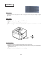
6 Belt Cleaning
Belt Cleaning Process means that the residual toner adhering to the OPC belt surface is
mechanically scavenged.
(1). Structure of Belt Cleaning
1 . Blade for the belt cleaning is located to the belt cartridge as shown in Fig.4-7.
(2). Process of Belt Cleaning (Fig.4-19)
1 . There is a residual toner on the OPC belt as it has not been transferred in the
process of drum transfer.
2 . Residual toner is mechanically scavenged by the blade edge.
3 . Scavenged residual toner is collected to the waste toner pack by the waste toner
feeder.
Drum Transfering
Belt Cleaning
(Brade)
Belt
Discharging
(Erase Lamp)
Fig.4-19
4-18
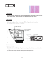
7 Second Transfer (Paper)
Second Transfer Process means that the toner image on the transfer drum is transferred
onto the transported paper.
(1). Structure of Belt Cleaning
1 . Transfer roller for the second transfer is located as shown in Fig.4-7.
2 . Transfer roller is normally separated from the transfer drum.
3 . Transfer roller is positively biased by the power supply THV.
4 . Transfer roller contacts to the transfer drum in the second transfer process.
5 . Transported paper passes between the transfer roller and transfer drum.
(2). Process of Belt Cleaning (Fig.4-20)
1 . Paper is transported as synchronizing with the transfer drum.
2 . Transfer roller operates as synchronizing with the transported paper, and
contacts with the transfer drum through the transported paper.
3 . Transported paper passes between the transfer roller and transfer drum.
In this instance, the positive high voltage (THV) is injected to the transfer roller.
4 . Negatively charged toner is moved to the positively charged paper.
5 . Transported paper with the toner transferred is transported to the paper
discharging process.
4-19
Paper Discharger
Transfer Drum
Transfer Roller
Toner Image
VAC
THV
Paper
Fig.4-20
4-20
VAC: Power Supply for Paper
dischargeing
THV: Power Supply for Transfer
Roller Bias.
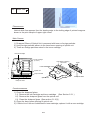
8 Paper Discharging
Paper Discharging Process means that the transported paper on which the transfer has
been completed is separated from the transfer drum by applying AC charge to the paper.
(1). Structure of Paper Discharge (Fig.4-21)
1 . AC charger unit for discharge of paper is located as shown in Fig.4-7.
2 . AC charger unit consists of the case and charger wire.
3 . High alternate voltage (VAC) is injected to AC charger unit.
(2). Process of Paper Discharge (Fig.4-21)
1 . Paper has been adhered to the transfer drum in the transfer process.
2 . Paper is neutralized (discharged) in terms of the electrical charge by injecting to
the paper the alternate voltage generated by the discharger.
3 . Paper is separated from the transfer drum and subsequently transported to the
fusing (fixing) process.
Paper Dischrger
Transfer Drum
Transfer Roller
Toner
VAC
THV
Paper
Fig.4-21
4-21
9 Drum Cleaning
Drum Cleaning Process means that the residual toner on the transfer drum is removed.
(1). Structure of Drum Cleaning(Fig.4-22)
1 . Drum cleaning unit is located as shown in Fig.4-7.
2 . Drum cleaning brush is a semiconductor type fur brush to clean the surface of
transfer drum as rotating. However, the cleaning brush stays away from the
transfer drum while imaging on the transfer drum.
3 . Drum cleaning roller is positively biased by the positive voltage FCBV(V).
4 . FCBV(V) is injected to the cleaning brush as well, and the cleaning brush is
self-biased by the resistance of brush.
5 . Drum cleaning roller rotates as contacting to the drum cleaning brush.
(2). Process of Belt Cleaning (Fig.4-22)
1 . There is the residual toner on the surface of transfer drum after the paper
transfer process.
2 . Drum cleaning brush is positively self-biased. Drum cleaning brush has the
negatively charged residual toner fall off from the surface of transfer drum, and
electrically absorbs the residual toner into the drum cleaning brush.
3 . Drum cleaning roller has been biased to the positive FCBV(V), the residual toner
absorbed into the drum cleaning brush is attracted by the positive FCBV(V) is
adhered to the surface of drum cleaning roller.
4 . Waste toner adhering to the surface of drum cleaning roller is scavenged by the
cleaning blade and collected to the waste toner pack by the waste toner feeder.
4-22
Cleaning Roller
Cleaning Brush
Waste Toner Feeder
Residual
Toner
FCBV
FCBV: Cleaning Roller
Drum Claening Unit
Transfer Drum
Power Supply for cleaning
Roller Bias
Fig.4-22
4-23
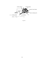
4.1.2 Optical System
This printer employs a semiconductor laser diode as a light source. This laser diode is
controlled by the fast switching according to transmitted image data (video signal).
The generated laser light scans over the OPC belt through a polygon mirror and lens, by
which electrostatic latent images will be formed on the OPC belt.
(1). Structure of Optical System (Fig.4-23)
Optical unit is located as shown in Fig.4-23.
Optical unit consists of following parts.
1 . Laser Unit
: Light emitting source incorporating a laser diode.
2 . Cylinder Lens
: Condenser of laser beam.
3 . Polygon Mirror
: Hexhedral mirror scanning the laser beam.
4 . F- Lens
: Focus lens for laser beam.
5 . Scanner Motor
: Motor to rotate the polygon mirror.
6 . Mirror
: Reflecting mirror for the laser beam path.
7 . LDC
: Laser diode control circuit.
8 . PD
: Photo detector.
9 . BTD Mirror : Beam timing detector mirror to guide the laser beam to PD.
9
2
6
4
8
7
5
1
2'
3
Fig.4-23
4-24
(2) Specification : Specification of Optical Unit is described as follows:
Item
Specification for SL1
Rated Output of Laser
Diode
5 mW.
Wave Length of Laser
Beam
Approx.785 nm.
600 dpi.
Scanning Density
220 mm.
Scanning Width
Rotations Per Minutes
of Scanner Motor
Number of Polygon
Mirror Faces
23,936 rpm.
6.
4-25
4.1.3 Paper Transportation System
(1). Outline
This printer employs the automatic paper feeding with the paper cassette.
When toner images are formed on the transfer drum through the operations of print
system and transfer system, a paper is fed by the pick-up roller and transported to the
registration roller. The transported paper is further transported to the transfer, fuser
and exit part by the registration roller synchronizing with the rotation of the transfer
drum.
(2). Structure of of Paper Transportation System (Fig.4-23)
Paper Transportation System consists of following parts.
1 . Paper Cassette
2 . Pick-Up Roller
3 . Registration Roller
: Case to accommodate papers to be automatically fed.
: Roller to feed paper one by one, preventing multi-feed.
: Roller to transport papers as synchronizing with the
transfer drum.
4 . Transfer Part
: Print processing part consisting of transfer drum and
transfer roller to transfer a toner image on to papers.
5 . Paper Discharger Unit : Corona generator to generate AC corona for separating
papers from the transfer drum.
: Mechanical part to fuse the toner image with the heat
6 . Fuser Unit
roller and fix it on the paper.
7 . Paper Exit Unit
: Mechanical part to exit the fused paper from the printer.
8 . Paper Exit Roller
: Roller to exit papers from of the printer.
4-26
7
8
6
5
4
3
2
1
Fig.4-24
1 . Paper Cassete @
2 . Pick-Up Roller @ @
3 . Resistration Roller
4 . Transfer Part @ @
4-27
5 .@Paper Discharger Unit
6 .@Fuser Unit
7 . Paper Exit Unit
8 . Paper Exit Roller
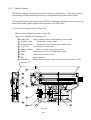
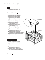
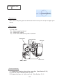
4.1.4 Fusing Unit (Fig.4-25)
Fusing Unit employs the thermal fusing system containing the heater in the roller.
Papers carrying the toner images pass between the heat rollers. Heat and
pressure is applied to the paper when passing between the heat rollers so that the
toner image is melted and fused on the paper.
(1). Structure
Fusing Unit consists of the following component members:
1 . Fusing Roller
2 . Back-up Roller
3 . Fusing Heater
4 . Thermistor
5 . Thermal Fuse
6 . Oil Bottle
7 . Cleaning Roller
:
:
:
:
:
:
:
incorporates the heater.
is a pressure roller to incorporates the heater.
is heated by the halogen lamp.
is a sensor to detect temperature of fuser roller’s surface.
prevent the fuser roller from being excessively heated up.
contains the silicone oil for fusing.
cleans the fuser roller.
7
4
6
5
1
2
3
Fig.4-25
4-28
(2). Process of Fusing (Fig.4-26)
1 . Silicone oil supplied from the oil bottle is applied to the surface of fuser roller
and back-up roller.
2 . Toner image is transferred on the paper, but not yet fused on the paper.
3 . Tansported paper passes between the heater roller and back-up roller.
4 . Each roller is heated up to approx.140 C, and received approx.156N from
the opposite heat roller.
5 . When the paper carrying the toner images passes between the tow heat
rollers, the toner images are melted and fused on the transported papre.
6 . The paper carrying the fused image is separated from the heat rollers, and
ejected from the printer.
Toner Image
C
M
(a). Before Fusing
Y
M
Y
Paper
Fixed Toner
(b). After Fusing
R
M
Fig.4-26
4-29
G
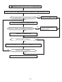
4.2 Structure of Control System
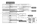
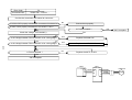
4.2.1 Basic Structure
(1). Electrical System and Function
Most of main electrical parts of this printer is controlled by MCTL P.W.B.
Structure of Sequence Control
Basic structure of the sequence control is exhibited in Fig.4-27.
1 . Print Process Control
: To control the print process from the paper
feed through paper exit.
2 . Laser Output Control
: To control automatically the laser output to
the default.
3 . Fuser Temperature Control: To control the fuser heater so that temperature
of fuser roller and back-up roller will be the default.
4 . Toner Sensing Control
: To control the sensing procedures of toner empty
status.
5 . Interface Control
(Video Signal)
: To process the input and output signal with the
external controller (host).
6 . Operator Panel Indicator
: To display the printer operation status in the
operator panel indicator.
7 . Error Control
: To control the safe stop procedures when errors
occur in the printer.
4-30
Operator
Panel
Cooling
Fan
Scanner
Motor
DM
Host Computer
Belt
Sensor
I/F
I/F
Drum
Sensor
ATC (4 pcs.)
LDU
Y
M
C
PD
K
Sequential Control
Control
Laser Control
Thermal Control
4-31
Controller
Toner Concentration Control
CPU
Operator Panel Control
Error Clearance Program
Cleaning Roller
Sensor
Paper Sensor
High Voltage Unit
Paper Feed Sensor
Oil Sensor
Fusing Unit
DC Power
Supply Unit
Paper Empty Sensor
Interlock Switch
Paper Size Sensor
Paper Exit Sensor
OHP Sensor
Drum Jam Sensor
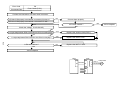
Fig.4-27
Main
Motor
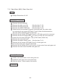
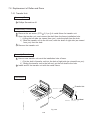
Layouts & Functions of Electrical Parts
1 . Print P.W.B. (Fig.4-28)
No.
Name
Function
1
MCTL P.W.B.
To control the series of processes of the Printer: Fuser
Temperature Control, Laser Output Control, Operator
Panel Indication, Toner Empty Sensing Control, Error
Processing Control, Interface Control.
2
Panel Indicator P.W.B.
To display the Printer's operation status and support
the manual input switch.
3
LDU P.W.B.
To control the drive and output of the laser diode to be
included in the optical unit.
4
PDU P.W.B.
To sense the emission of laser diode and also the
beam position to be included in the Optical unit.
5
Erase Lamp
To discharge the OPC belt by radiating the LED beam
onto the OPC belt to be included in the Optical unit.
6
IOD1 P.W.B.
To relay the signals between the controlled parts and
MCTL P.W.B., and to drive the controlled parts.
7
IOD2 P.W.B.
- Ditto -
8
DC Power Supply
(LVPS) P.W.B.
To provide the Printer with the power supply for the
printer control.
9
High Voltage Power
Supply (HVU) P.W.B.
To provide the Printer with the high voltage power
supply that is necessary for the printing process.
4-32
5
2
Erase Lamp
Panel
7
I OD2
6
9
High Voltage Power
Supply (HVU) P.W.B.
I OD1
1
MC TL
8
DC Power Supply
(LVPS) P.W.B.
3
LD U
4
Fig.
4-28
4-33
PDU
2 . Motor (Fig.4-29)
No.
Name
Code
Function
1
Main Motor
MM
To drive the OPC belt and the paper
transport system.
2
Developing Motor
DM
To drive the toner cartridge and the
developing system.
3
Scanner Motor
4
Ozone Fan Motor
OZFAN
To exhaust the ozone from printer
(charger unit).
5
Heater Fan Motor
HTFAN
To exhaust the heat of fusing unit.
6
Controller Fan Motor
SCM
CTLFAN
4-34
To scan the laser beam.
To exhaust the heat of power supply unit
and Interface Controller.
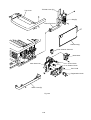
2 . Layout of Motors
Ozone Fan
Heater Fan
Main Motor
Exit Cover Door SW.
Developing Motor
Controller Fan
Front Cover Door SW.
Back Cover Door SW.
Scanner Motor
Fig.4-29
4-35
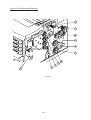
3 . Clutch and Solenoid (Fig.4-30)
No.
1
Name
Feeder Clutch
Code
Function
PCLU
To feed papers by coupling the feeding
roller to the main gear unit at timing of
the paper feeding.
2
Registration Clutch
RECL
To transport papers by coupling the
registration roller to main gear unit as
synchronized with the rotation of transfer
drum.
3
Fuser Clutch
FUCL
To drive the fusing roller by coupling the
fuser unit to the main gear unit.
FBCL
To drive the brush of drum cleaner by
coupling the cleaner clutch to the main
gear unit at timing of the drum cleaning.
4
Cleaner Clutch
5~8 Developer Clutch
9
Developer Solenoid
Unit
10
Transfer Retract
Solenoid
11
Cleaner Retract
Solenoid
DVCL
(Y,M,C,K)
To drive the Mg. roller of desired color
toner cartridge by coupimg said toner
cartridge to the developer gear unit at
timing of the developing.
PSL(MC)
PSL(KY)
To relocate the desired color toner
cartridge to developing position at timing
of the developing.
TRSOL
To have the transfer roller contact to the
transfer roller’s surface at timing of the
second transfer.
FBSOL
To have the drum cleaner contact to the
transfer roller’s surface at timing of the
drum cleaning.
4-36
Layout of Clutches and Solenoids
11
3
4
10
2
1
8
6
5
9
Fig.4-30
4-37
7
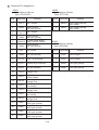
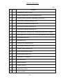
4 . Sensors
No.
Name
Code
Function
1
Paper Size Sensor
PSU
Photo sensor to detect the paper size.
2
Paper Feeder Sensor
PT1
Photo sensor to detect the paper is fed
from the paper cassette.
3
Paper Exit Sensor
PT2
Photo sensor to detect that paper is
exited from the paper exit unit.
4
Paper Sensor
PEU
Photo sensor to detect if paper is loaded
or empty in the paper cassette.
5
Oil Sensor
OIL
Photo sensor to detect if the fuser unit
oil is empty or not.
6
OHP Sensor
OHP
Photo sensor to detect that material in the
paper cassette is OHP.
7
Drum Paper Jam
Sensor
DPJ
Photo sensor to detect that paper is
winding around the transfer drum.
8
Drum Encoder
EN
Photo sensor to detect irregular rotation
of the transfer drum.
9
Photo Belt Sensor
10
Toner Detecting Sensor
11
PBS
Photo sensor to detect the connecting
position of the OPC belt.
TPD/TTR
Photo sensor to detect if the toner is
empty or not for each toner cartridge.
Waste Toner Sensor
WTS
Photo sensor to detect that the waste
toner bottle is full of waste toner.
12
Developing Photo
Sensor
GHP1,
GHP2
Photo sensor to detect the early position
of toner cartridges.
13
Cleaning Roller
Sensor
CRS
Photo sensor to detect if the cleaning
roller is available or not in the fuser unit.
14
Temperature Sensor
for Fuser unit
TH
4-38
Thermistor to detect the fuser
temperature.
Layout of Sensors
14. Temperature Sensor
for Fuser Unit
3. Paper Exit Sensor
7. Drum Paper Jam
Sensor
13. Cleaning Roller Sensor
5.Oil Sensor
10. Toner Detecting
Sensor
9.Phot Belt Sensor
8. Drum Encoder
12. Developing Photo
Sensor
6. OHP Sensor
11. Waste Toner Sensor
2. Paper Feeder
Sensor
4. Paper Sensor
1. Paper Size Sensor
Fig.4-31
4-39
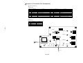
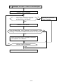
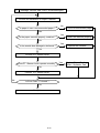
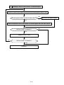
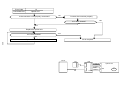
4.2.2 Control System
(1). Control of Print Process
Micro CPU mounted on the MCTL P.W.B. controls the print processes.
[Print Sequence Diagram]
Operator
Panel
Cooling
Fan
Scanner
Motor
DM
Host Computer
Belt
Sensor
I/F
I/F
Drum
Sensor
ATC (4 pcs.)
LDU
Y
M
C
PD
K
Sequential Control
Control
Laser Control
Thermal Control
Controller
Toner Concentration Control
CPU
Operator Panel Control
Error Clearance Program
Cleaning Roller
Sensor
Paper Sensor
High Voltage Unit
Paper Feed Sensor
Oil Sensor
Fusing Unit
DC Power
Supply Unit
Paper Empty Sensor
Interlock Switch
Paper Size Sensor
Paper Exit Sensor
OHP Sensor
Drum Jam Sensor
Fig.4-32
4-40
Main
Motor
1 . Control Block Diagram(Fig.4-32)
No.
Name of Control
Description
(a)
Sequence Control
To control the print sequence of
printer.
(b)
Temperature Control
To control the temperature of fuser
unit.
(c)
Toner Empty Sensing Control
To control the toner empty status of
each toner cartridges.
(d)
Operator Panel Control
To control the operator panel indication
and the operation signals.
(e)
Error Processing Control
To sense the errors occurring in the
printer and the stop procedures.
(f)
Interface Control
To control the receipt and transmission
of the interface signals from the
external controller.
(g)
To control the laser scanning and laser
power.
Laser Control
4-41
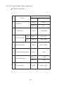
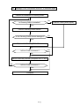
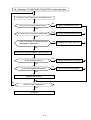
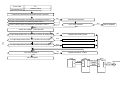
(2). Laser Drive Control Circuit
Laser Drive Control Circuit (LDC) consists of the video signal input circuit, laser drive
circuit, laser diode, output sensing circuit and output control circuit, as shown in
Fig.4-33.
Operation
1 . When the video signal is inputted, the laser drive control circuit has the laser
diode switched on and radiated according to the video signal.
2 . Radiated laser beam is sensed by the photo detector (PD), and the detecting
signal is fed back to the output control circuit.
3 . Output control circuit controls the radiation output to be constant, by comparing
the laser output default with the feed-back value transmitted from the output
sensing circuit.
4 . Laser beam scanned by the scanner motor is sensed by the beam detector
(PD), and then, the beam detecting timing (BDT) signal will be outputted.
4-42
MCTL P.W.B.
OPC Belt
PRINT Signal
Frequency Control
Circuit
F - ƒLens
4-43
PD
Scaner Motor
Laser
Beam Scanning
Control Circuit
Synchronizie
Control Circuit
BDT
LCD P.W.B.
VIDEO Signal
Fig.04-33
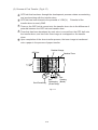
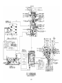
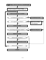
(3) Control of Fusing Temperature
Each rollers of the fusing unit are controlled to maintain the appropriate temperature
so that toner will be fixed on a print paper.
1 . Basic Structure of Temperature Control(Fig.4-34)
FLS
TFU1/TFU2
TH
RY
GA/CPU
CM1
CM2
CM3
Q
HR
BR
: Thyristor to control the on/off operation of power supply to the heat
lamp.
: Temperature fuse to shut down the circuit for safety when it will
be too hot within the fusing unit.
: Temperature sensor to detect the surface temperature of the heat
roller(HR).
: Relay to prevent the further heating when it will be hotter than the
set point within the fusing unit.
: Process circuit to process the temperature signal(micro computer).
: Sensor circuit for temperature signal (for ACOFF signal).
: Sensor circuit for temperature signal (for HON signal).
: Sensor circuit for temperature signal (for processing).
: Sensor circuit for shut-down by the thermistor (for THERR signal).
: Heat lamp for the heat roller.
: Heat lamp for the back-up roller.
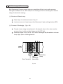
2 . Characteristics of Signal
HON-N
ACOFF
THERR
AD
: To
: To
: To
: To
turn on/off the heater in side the fusing roller.
turn off the relay RY1 when it is sensed too hot.
detect the shut-down by the thermistor.
convert the temperature sensing signal to AD.
3 . Controlled Temperature and Safety
TPS
TA
Temperature
( C)
150 C TS
Time
4-44
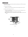
RY-1
ACOFF-P
RY-1
AD
CM3
PC
FLS
HON-N
Fusing Unit
CM1
4-45
TFU1 TFU2
CM2
BR
Q
THERR ACOFF HON
GA/CPU
Fig 4-34: Basic Structure of Fuser Control
HR
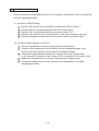
TS
: To maintain the set point (temperature) for fusing of toner to be approx.150 C as
appropriate by turning on/off the thyristor.
TA
: Reference temperature ( approx.175 C ) to identify that it is excessively hot
inside the fusing unit. When it reaches to this point, the relay RY turns off,
the power supply to the heat lamp is shut down, and the printer stops the
operation.
TPS : Limit temperature to have the temperature fuse start melting and shutting down
the power supply to the heat lamp if the temperature control circuit should break
down. When the temperature fuse is molten, the printer will stop the operation.
4 . Safety Control by Temperature Control Signal
H0
H2
H3
H4
: When THERR signal is inputted, the operator panel indicates “H0”, and the
printer will stop the operation.
: If the temperature of fusing unit will not reach to the required point “T1” after the
elapse of certain time, the operator panel indicates “H2”, and the printer will stop
the operation.
: If the “Heater On” signal is still continued after the elapse of certain time, the
operator panel indicates “H3”, and the printer will stop the operation.
: If the temperature within the fusing unit becomes unusually hot and when
ACOFF signal is inputted, the operator panel indicates “H4”, and the printer will
stop the operation.
4-46
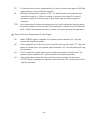
(5). Interface Control
1 . General
(a). Interface Type
Video Interface handles image data and corresponds to print dots, but does not
accumulate images with the buffer. Video signals of the inputted image data
switches the semiconductor laser diode to form a print image.
(b). Interface Connection
Operator
Panel
Laser Printer
Controller
Hitachi Color
Laser Printer
SL1
Host
System
(LPC)
Fig.4-36: Interface Circuit (Internal Connecting System)
Interface connector of the laser printer SL1 is connected to the host system as
shown in Fig.4-36.
4-47
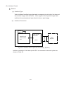
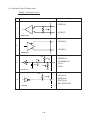
(c). Interface Circuit (Printer side)
Table4.1 Interface Circuit
No.
Interface Circuit
Name of Signal
VIDEO-N
1
150
VIDEO-P
M5M34050
HSYNC-N
2
HSYNC-P
M5M34050
+5V
220
22
COMMAND-N
3
0.01 F
PRREQ-N
ID1-N
330
ID2-N
GND
GND
SN74LS14
+5V
3.3K
VSYNC-N
IREADY-N
4
STATUS-N
KEY-STATUS-N
SN7406
4-48
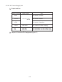
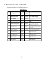
(d). Connector Pin Assignment:
Connector type of the Printer side is 128A-064S2B-:13A(DDK) or the equivalent.
Table 4.2: Connector Pin Assignment
Pin No.
1A
2A
3A
4A
5A
6A
7A
8A
9A
10A
11A
12A
13A
14A
15A
16A
17A
18A
19A
20A
21A
22A
23A
24A
25A
26A
27A
28A
29A
30A
31A
32A
Signal Name
PSGND
PSGND
PSGND
PSGND
PSGND
PSGND
PSGND
PSGND
VIDEO-P
RET(GND)
HSYNC-P
ID2-N
RET(GND)
RET(GND)
RET(GND)
RET(GND)
RET(GND)
RET(GND)
RET(GND)
RET(GND)
ID1-N
RET(GND)
Reserve
Reserve
RET(GND)
RET(GND)
RET(GND)
RET(GND)
RET(GND)
RET(GND)
RET(GND)
RET(GND)
Pin No.
1B
2B
3B
4B
5B
6B
7B
8B
9B
10B
11B
12B
13B
14B
15B
16B
17B
18B
19B
20B
21B
22B
23B
24B
25B
26B
27B
28B
29B
30B
31B
32B
4-49
Signal Name
+5V
+5V
+5V
+5V
+5V
+5V
+5V
+5V
VIDEO-N
Reserve
HSYNC-N
Reserve
VSYNC-N
Reserve
STATUS
IREADY-N
Reserve
COMMAND
PRREQ-N
Reserve
Reserve
KEY_STATUS-N
Reserve
Reserve
Reserve
Reserve
Reserve
Reserve
Reserve
Reserve
Reserve
Reserve
4.2.3 DC Power Supply Unit
1 . Output and Use
Output Terminal
Rated Output
+5V-1
+5V-1R
Use
For control of Printer.
4.8~5.3V, 7.5A
(8.5A)
+5V-2
For control of Laser.
For control of Interface.
+24V-1
+24V, 4.5A
For control of Printer charging.
HP
HN
120V, 8A
220V, 5A
For connection of Fuser Heater (HP).
For connection of Fuser Heater (HN).
2 . Layout of Connector Pin Assignment(Fig.4-37)
4-50
ACN1
ACN3
1
1
HP
ACN2
4-51
1
HN
Main SW
Inret
L
PC Pin
Black
Black
N
White
White
Fig.4-37
2 . Connector Pin Assignment
ACN1
Manufacturer: MoLex
Type: 53313-2215
Pin#.
Signal Name
1
+5V-1
2
ACN2
Manufacturer: MoLex
Type: 5277-02A
Interface
Interface
Pin#.
Signal Name
+5V-1 Output
1
DSW-O
+24V Output through
Door Switch.
SGND
Signal Ground
(+5V type ground)
2
DSW-I
+24V Output through
Door Switch.
3
+5V-1
+5V-1 Output
4
SGND
Signal Ground
(+5V type ground)
5
AC Zero-Cross Signal
ACSYNC-N (Open Collector Output)
ACN3
Manufacturer: MoLex
Type: 5566-04A
6
SGND
Signal Ground
(+5V type ground)
7
+24V
+24V Output not through
Door Switch
8
SGND
Signal Ground
(+5V type ground)
1
+5V-2
+5V-2 Output
9
+5V-1R
+5V through the relay when
+24V-1 is shut down.
2
+5V-2
+5V-2 Output
3
SGND
Signal Ground
(+5V type ground)
4
SGND
Signal Ground
(+5V type ground)
10
AC Forced Shut-Down
ACOFF-P Signal(Pull-Up required).
11
HON-N
Heater On Signal
(Pull-Up required).
12
Test I2
Terminal for Dielectric
Strength Test.
13
+24V-1
+24V Output corresponding
to Door Switch.
14
Test O2
Terminal for Dielectric
Strength Test.
15
+24V-1
+24V Output through
Door Switch.
16
Test I1
Terminal for Dielectric
Strength Test.
17
+24V-1
+24V Output through
Door Switch.
18
Test O1
Terminal for Dielectric
Strength Test.
19
PGND
Power Ground
(+24V type ground)
20
PGND
Power Ground
(+24V type ground)
21
PGND
Power Ground
(+24V type ground)
22
PGND
Power Ground
(+24V type ground)
4-52
Pin#.
Signal Name
Interface
4.2.4 DC High Voltage Power Supply Unit
1 . Output and Function
Power Supply (P/S)
No.
1
2
3
Function
Name of P/S Approx.Output Voltage
CHV(-)
4.6kV
HVRD6190
619V
Charging
CBV(-)
200V~900V
Y,M
DBV(-A)
200V~400V
C,K
DBV(-B)
200V~400V
400V~3,000V
First Transfer
Developing Bias
4
Second Transfer
THV(+)
5
Transfer Roller Cleaning
THV(-)
600V
ACV(~)
4.9KV
DCV(+)
200V
6
7
Paper Discharging
Drum Cleaning
FCBV
4-53
200V~1,500V
2 Layout of Connector Pin Assignment
Connector Pin Assignment
BCN1
Manufacturer: MoLex
Type: 53313-1815
Signal Name
Pin#
1
Interface
{24v |1
Signal Name
Pin#
{24V |1
Interface
2
PGND
PGND
3
FUCHK
Senor Signal of Fuser Unit Installation.
4
PGND
PGND
5
ACVON-N
AC Output ON Signal
6
PWMON-N
PWM Control On Signa
7
CHVON-ON
CHV Output ON Signal
8
CHVERR
CHV ERROR Sensor Signal.
9
CBVPWM-N
CBV PWM Control Signal.
10
THVRON-N
THV ON Signal
11
DBVYMPWM-N
DBV PWM ControlSignal.
12
THVPWM-N
THV PWM Control ON Signal.
13
DBVCKPWM-N
CBV PWM Control Signal.
14
THV |
Transfer Voltage Select Signal.
15
FCBVPWM-N
FCBV PWM Control Signal.
16
TH1
Thermistor Temperature Sensor Signal.
17
NC
NC
18
TH2
Thermistor Temperature Sensor Signal.
BCN2
Manufacturer: MoLex
Type: 53324-0410
Pin#
Signal Name
Interface
1
TH1
Thermistor1
2
TH2
Thermistor2
3
FUCHK
Fuser Check
4
FUCHKGND
GND
4-54
18
17
2
1
BON1
FCBV
DBV(K)
DBVCK
DBV(C)
1
BCN2
4
FCBV
DBVYM
High Voltage
MODEL
THVR
AC
DBV(M)
THV
CBV
ACOUT
THV
DBV(Y)
CHV
CHV
THV
CHVOUT
Fig.4-38
CBV
1
(2 „æ ^ C 2
v2s )
EDCN2 FIOD1
´ | … ‹ d
(22Pins
)
FIOD1 P.W.B |Power Supply
Unit
s
No.
1
3
5
7
9
11
13
15
17
19
21
M
…
{5v |1
{5v |1
ACSYNC |N
{24V
{5v |1R
HON |N
{24 |1
{24 |1
{24 |1
PGND
PGND
s
No.
M
2 SGND
4 SGND
6 SGND
8 SGND
10 ACOFF |P
12 TESTI2
14 TESTO2
16 TESTI1
18 TESTO1
20 PGND
22 PGND
…
2
EDCN14 FIOD1
´ |
‡ (18´s 2 æ
´ |n [ l )X
(18Pins
)
FIOD1 P.W.B |High Voltage
Unit
s
No.
1
3
5
7
9
11
13
15
17
M
…
{24v |1
FUCHK
ACVON |N
CHVON |N
CBVPWM |N
(MC )PWM |N
DBV
(KY )PWM |N
DBV
FCBVPWM |N
NC
s
No.
M
2 PGND
4 PGND
6 PWMON |N
8 CHVERR
10 THVRON |N
12 THVPWM |N
14 THV |I
16 TH1
18 TH2
…
3
EDCN3 F H Œ
‚ p
(4Pins
)
FFor Factory Use
Only
s
No.
1
2
3
4
M
TESTO1
TESTI1
TESTO2
TESTI1
…
4
EDCN4 FIOD1 |h A X C b ‘
FIOD1 |Interlock Switch
s
No.
M
…
1 REARDOPEN |P
2 N.C
3 TOPDOPEN |P
4-56
5
14
EECN1 FMCTL |IOD2(20 s 2 æ)
(20Pins
)
FMCTL P.W.B |IOD2
EDCN1 FMCTL
´ |IOD1 (50
´ s 2 æ)
(50Pins
)
FMCTL P.W.B |IOD1 P.W.B
s
No.
1
3
5
7
9
11
13
15
17
19
21
23
25
27
29
31
33
35
37
39
41
43
45
47
49
M
…
SGND
SGND
{5v |1
{5v |1
{5v |1
{5v |1
I ^OAD2
I ^OAD1
I ^OAD0
I ^ODATA3
I ^ODATA2
I ^ODATA1
I ^ODATA0
TMLEDON |P
LEDON |N
TRSLON |P
FBSLON |P
FBCLON |P
SPSLLON |P
PKCLLON |P
ELON |P
PBSEN |N
HPSEN |N
CTFANON |P
HTFANON |P
s
s No.
M
…
2 PGND
4 PGND
6
{24v |1
8 HON |N
10 SGND
12 ACOFF |P
14
{5v |1R
16
{24v
18 RHSON
20 AHUMB
22 ACVON |N
24 CHVON |N
26 PWMON |P
28 CBVPWM |N
(MC )PWM |N
30 DBV
(KY )PWM |N
32 DBV
34 FCBVPWM |N
36 THVRON |N
38 THVPWM |N
40 THV |I
42 TH2
44 TH1
46 OILLES |P
48 TMASEN1
50 TMASEN2
No.
1
2
3
4
5
6
7
8
9
10
11
12
13
14
15
16
17
18
19
20
M
…
DCL(C )ON |P
(M )ON |P
DCL
(Y )ON |P
DCL
(K )ON |P
DCL
(KY )ON |P
PSL
(MC )ON |P
PSL
MMCLK
MMON |N
MMREV |N
MMENC
DMCLK
DMON |N
ISCK
IDATA
ILOAD
PKCLUON |P
RECLON |P
SPSLUON |P
OZFANON |P
FUCLON |P
35
6
( A N ‘ G [)^ ´(14 s 2 æ
EDCN9 FIOD1
´ |IOD2
(14Pins
)
FIOD1 P.W.B |IOD2 P.W.B
s
No.
1
2
3
4
5
6
7
8
9
10
11
12
13
14
´ |n [ l )X
EDCN15 FIOD1 |N [ j O [ ¢
FIOD1 |Cleaning Roller Sensor
s
M
…
FBCLON |P
FBSLON |P
TRSLON |P
OZFANERR
{24v |1
{24v |1
{24v |1
PGND
PGND
PGND
{5v |1
SGND
PHSON |P
AHUMB
4-57
No.
M
1
{5v |1
2 CLROL |N
3 SGND
…
12
7
EDCN5
@ @ @
@ @ @
@ @ @
@ @ @
@ @ @
s
EDCN10 FIOD1
´ | tp@
@ @ @
FIOD1
´ |PT2
Z T
(PT2)Sensor
@ @ @
FIOD1 P.W.B |Paper Exit
(HTFAN
)
@ @ @
FIOD1 P.W.B |Heater
Fan
FIOD1 | ªJ Z b g L ‡
m
FIOD1 | oZ s1
T
@FIOD1 |h
Z T
)
@FIOD1 |Upper Paper Empty (PEU
Sensor
(PT1Sensor
)
FIOD1 |Paper Feeding
(EN )
@FIOD1 |Drum Encoder Sensor
No.
1
2
3
4
5
6
7
8
9
M
{5v |1
HPSEN |N
SGND
{5v |1
PEU |P
SGND
{5v |1
PT1 |N
SGND
s
…
EDCN11 FIOD1
´ |
x g
@ @ @
FIOD1 I´C |
@ @ @ @ FIOD1
´ | “ t
)
@ @ @ @ FIOD1 P.W.B |Belt (PBS
Sensor
@ @ @ @ FIOD1 P.W.B |Oil (Sensor
OIL)
@ @ @ @ FIOD1 P.W.B |Drum Paper Jam Sensor
EDCN6 FIOD1 | ªJ Z b g T C Y Z T
@ @ @
FIOD1 |OHP
Z T
@ @ @
FIOD1 |Upper Paper Size Sensor
@ @ @
FIOD1 |OHP Sensor
No.
1
2
3
4
5
6
7
8
9
10
M
{5v |1
PSU1
PSU2
PSU3
PSU4
SGND
{5v |1
OHPSENU
SGND
SGND
s
…
9
EDCN7
@ @ @
@ @ @
@ @ @
@ @ @
@ @ @
s
FIOD1
´ |g i [ ‡Y
FIOD1 g´i |[ ‡M
g i [ ‡C
@FIOD1
´ |
FIOD1 g´i |[ ‡K
@FIOD1
´ |
C [ Y
@FIOD1 P.W.B |Toner Empty (Sensor
Y,M,C,K)
No.
1
2
3
4
5
6
7
8
9
10
11
M
…
TLES(K ) |P
(Y ) |P
TLES
(M ) |P
TLES
(C ) |P
TLES
TLES |G
SGND
LEDON |P
TLESCHK
SGND
{24v |1
ELON |N
10
EDCN13 FIOD1
´ |
R g [ t @
FIOD1 P.W.B |Controller Fan
s
M
…
{5v |1
PT2 |N
SGND
HTFANON |P
PGND
HTFANERR
13
8
s
No.
1
2
3
4
5
6
No.
M
…
1 CTFANON |P
2 PGND
3 CTFANERR
4-58
No.
1
2
3
4
5
6
7
8
9
M
…
PBSEN |N
{5v |1
SGND
OILLES |P
{5v |1
SGND
E4SEN |N
{5v |1
SGND
19
15
EECN3 FIOD2 | » SLYMC
FIOD2 |Developer Solenoid
EECN17 FIOD2 | » N b Y‘
(Y )
FIOD2 |Developer Clutch
s
s
No.
M
…
1
{24v |1
2 NC
(C )ON |N
3 DCL
16
EECN16 FIOD2 | » N b M‘
(M )
FIOD2 |Developer Clutch
s
No.
M
…
1
{24v |1
2 NC
(M )ON |N
3 DCL
No.
1
2
3
4
5
6
7
8
9
10
11
12
13
M
{5v |1
TBFL2 |N
SGND
{5v |1
GHPSEN1
SGND
{5v |1
GHPSEN2
SGND
(YM )
PSL
…
{24v |1
{24v |1
(KC )
PSL
22
17
EECN6 FIOD2 |I ] t @
FIOD2 |Ozen Fan
EECN14 FIOD2 | » N b C‘
(C )
FIOD2 |Developer Clutch
s
s
No.
M
…
1
{24v |1
2 NC
(Y )ON |N
3 DCL
No.
M
…
1 OZFANON |P
2 PGND
3 OZFANERR
23
18
EECN7 FIOD2 | W X g N b ‘
FIOD2 |Registlation Clutch
EECN13 FIOD2 | » N b K‘
(K )
FIOD2 |Developer Clutch
s
s
No.
M
…
1
{24v |1
2 NC
(K )ON |N
3 DCL
20
EECN9 FIOD2 | Ł N b ‘
FIOD2 |Fuser Clutch
s
No.
M
…
1
{24v |1
2 NC
3 FUCLON |N
21
EECN11 FIOD2 |N [ i N b ‘
FIOD2 |Cleaner Clutch
s
No.
M
…
1
{24v |1
2 NC
3 FBCLON |N
4-59
No.
1
2
3
4
M
…
{24v |1
NC
NC
RECLON |N
25
32
EACN2 F … ‹ d „ h| ASW (
d ‹^ C 2
v s )
(2Pins
)
FPower Supply Unit |Interlock
Switch
EECN10 FIOD2 |N [ i \ m C h
FIOD2 |Cleaner Clutch
s
No.
1
2
3
4
s
M
…
{24v |1
NC
NC
FBSLON |N
26
No.
M
1 DSW |O
2 DSW |I
…
31
EECN8 FIOD2 | ] \˚ m C h
FIOD2 |Transfer Solenoid
s
No.
1
2
3
4
EACN3 F … ‹ d „ R| g [ d „(
d ‹^ C 4
v s )
FPower Supply Unit |MCTL
M
…
{24v |1
NC
NC
TRSLON |N
s
No.
M
1
{5v |2
2
{5v |2
3 SGND
4 SGND
…
27
33
EECN5 FIOD2 |
UN b ‘
FIOD2 |Paper Feeding Clutch
s
( V O } ⁄ p6s ) |MCTL POCN
E Ł
)
@Fuser Unit |MCTL P.W.B (POCN
6Pins
No.
M
…
1
{24v |1
2 NC
3 PKCLUON |N
s
28
EECN12 FIOD2 | C
[ ^
FIOD2 |Main Motor
s
No.
1
2
3
4
5
6
7
8
9
M
MMRDY |N
MMON |N
MMCLK
PGND
{24v |1
SGND
{5v |1
MMENC
MMREV |N
34
EBCN2 F
‡
´ | Ł ( M n [ l 4X s )
(4Pins
)Unit
FHigh Voltage Unit |Fuser
s
EECN15 FIOD2 | » [ ^
FIOD2 |Developer Motor
No.
1
2
3
4
5
6
7
8
9
M
DMRDY |N
DMON |N
DMCLK
PGND
{24v |1
SGND
{5v |1
NC
DMREV |N
M
…
ACOUT |HP
FUCHKGND
TH2
ACOUT |HN
FUCHK
TH1
…
29
s
No.
1
2
3
4
5
6
…
4-60
No.
1
2
3
4
M
TH1
TH2
FUCHK
FUCHKGND
…
30
ELCN FMCTL |LDU (20 s 2 æ)
)
FMCTL |LDU(20Pins
s
No.
1
2
3
4
5
6
7
8
9
10
11
12
13
14
15
16
17
18
19
20
M
…
{5v |R
LDREF2
LDREF3
{5v |1
LDREF1
LDREF0
LREADY
LCONT2
LCONT1
VIDEO |P
VIDEO |N
BDT |P
BDT |N
SGND
SGND
SCMCLK
SCMRDY |N
SCMON |N
PGND
{24v |1
4-61
11
11
EDCN8 FIOD1 | ”
j b g
FIOD1 |Lower Feeder Unit
s
11
No.
1
2
3
4
5
6
7
8
9
10
11
12
13
14
15
16
17
18
M
…
{24v |1
NC
PKCLLON |N
NC
{5v |1
{5v |1
PEL |P
PSL1
SGND
PSL2
{5v |1
PSL3
OHPSENL
PSL4
SGND
SGND
OCST |N
NC
s
11
PSL
s
11
No.
1
2
3
4
5
6
7
8
9
10
11
12
13
14
15
16
17
18
M
…
{24v |1
PKCLLON |N
{5v |1
PEL |P
SGND
{5v |1
OHPSENL
SGND
OCST |N
NC
NC
{5v |1
PSL1
PSL2
PSL3
PSL4
SGND
NC
No.
1
2
3
4
5
6
M
{5v |1
PSL1
PSL2
PSL3
PSL4
SGND
…
No.
M
1
{5v |1
2 PEL |P
3 SGND
…
-4
PEL
s
11
-1
ELFU R l N ^
LFU Connector
-3
-5
OHPL
s
No.
1
2
3
4
-2
PKCLL
s
No.
M
…
1
{24v |1
2 NC
3 PKCLLON |N
4-62
M
…
{5v |1
OHPSENL
SGND
OCST |N(SGND)
5. Periodic Maintenance
5.1 General . . . . . . . . . . . . . . . . . . . . . . . . . . . . . . . . . . . . . . . . . . .5-1
5.1.1 Precaution in Handling . . . . . . . . . . . . . . . . . . . . . . . . . . . . . . . . .5-1
(1). List of maintenance tools . . . . . . . . . . . . . . . . . . . . . . . . . . . . . . .5-2
(2). List of consumables for maintenance . . . . . . . . . . . . . . . . . . . . . .5-3
5.1.2 Cleaning for periodic maintenance . . . . . . . . . . . . . . . . . . . . . . . .5-4
5.1.3 Periodic maintenance parts and maintenance cycle . . . . . . . . . . . .5-13
5.2 Periodic Maintenance Procedures . . . . . . . . . . . . . . . . . . . . . . . .5-15
5.2.1 Replacement of Belt Cartridge . . . . . . . . . . . . . . . . . . . . . . . . . . . .5-15
5.2.2 Replacement of Fuser Unit . . . . . . . . . . . . . . . . . . . . . . . . . . . . . .5-17
5.2.3 Replacement of Transfer Roller . . . . . . . . . . . . . . . . . . . . . . . . . . .5-20
5.2.4 Replacement of Paper Discharger Unit . . . . . . . . . . . . . . . . . . . . .5-22
5.2.5 Replacement of Drum Cleaner . . . . . . . . . . . . . . . . . . . . . . . . . . .5-24
5.2.6 Replacement of Ozone Filter . . . . . . . . . . . . . . . . . . . . . . . . . . . . .5-26
5.2.7 Checking of Paper Feeding Roller and Separator Pad . . . . . . . . . .5-27
5.2.8 Replacement of Transfer Drum . . . . . . . . . . . . . . . . . . . . . . . . . . .5-28
5. Periodic Maintenance
5.1 General
5.1.1 Precaution in Handling
Since a high quality laser printer is a precision equipment, the daily checking
and periodic maintenance is indispensable to maintain an expected hig
performance.
Following is the list of important precautions & action items as to
the maintenance and periodic replacement parts:
(1). Refrain from any operation, disassembly, and modification that are not
set out in this manual.
(2). When assembling or disassembling the printer, turn the power supply off
at first and unplug the power supply cord prior to commencing any work.
(3). Whenever having replaced any parts, confirm the replaced parts in place
prior to driving the printer.
(4). Read carefully and understand well any precaution or warning labels
affixed to any parts.
(5). Unless otherwise specified, precisely follow the reverse order of the
disassembly procedures for the re-assembly. Do not get confused with
the kind of removed screws and also length.
(6). Do not use any solvent for cleaning, no matter inside or outside of printer.
(7). It is strictly forbidden to dump the waste toner together with flammable
substances or throw it into the fire. This is a very important caution to
be respected.
5-1
(1). List of Maintenance Tools
Table 5-1 below lists up the maintenance tools for the printer.
Table 5-1
No.
Name of Tool
Function
1
Phillips Screwdriver #1
For M3
2
Phillips Screwdriver #2
For M4
3
Phillips Screwdriver (short shank) #2
For M4
4
Slotted Screwdriver #1
For slotted head screw
5
Slotted Screwdriver #2
For slotted head screw
6
Long-Nose Pliers
For general use
7
Pincette
For general use
8
Precision Driver Set (#1 ~ #6)
For general use
9
Gap Gauge
Adjustment of Gap
10
Pliers for C Ring
C Ring
11
Ruler (150mm)
For general use
12
Slide Caliper
For general use
13
Digital Meter
For general use
14
Handy Type Cleaner unique for toner
For cleaning
15
Soft Fur Brush
For cleaning
5-2
(2). List of Consumables for Maintenance
Table 5-2 below lists up the consumables for maintenance.
Table 5-2
No.
Name of Tool
Parts Code
Quantity
Function
1
Toner Cartridge (Y)
1 piece
Test Print
2
Toner Cartridge (M)
1 piece
Test Print
3
Toner Cartridge (C)
1 piece
Test Print
4
Toner Cartridge (K)
1 piece
Test Print
5
Cleaning Pad / Oil Bottle
1 piece
Test Print
6
Belt Cartridge
1 piece
Test Print
7
Recommended Paper (A4 or Letter)
5 sheets
Test Print
8
Recommended Paper (OHP)
2 sheets
Test Print
9
Cotton Cloth (Unwoven fabric)
10~15 pieces
Cleaning
10
Cotton Applicator
10~15 pieces
Cleaning
11
Grease
12
Vinyl Bag
10 gram
2 bags
*1: M.G stands for Molybdenum Grease.
5-3
M.G*1PS265
Disposal
5.1.2 Cleaning for Periodic Maintenance
See Table 5-3 for details of periodic maintenance cleaning to the following parts.
(1). Registration Roller
(2). Transfer Roller
(3). Paper Discharger
(4). Belt Cartridge
(5). Dustproof Glass of Optical Unit
(6). Printer Interior
WARNING
• Before starting any maintenance work, make sure to unplug the power
supply cord from the outlet.
• There is a risk of electric shock in working while the printer is energized.
5-4
Periodic Maintenance Cleaning Work
Table 5-3
1/2
Cleaning Work
No. Name of Parts
Description
Page
Cleaning Cycle *1
(Condition or Case)
Time *2
(minute)
Skill *3
Level
• Defective image
1
Registration
Roller.
1. Open transfer unit.
2. Clean rollers and neighbor, using a dry
cloth.
5-7
• Smeared paper
5-5
2
A,B,or
User.
2
A,B,or
User.
3
A,B,or
User.
• Periodic
maintenance.
• Damaged image
2
Transfer
Roller.
1. Open transfer unit.
5-8
2. Clean rollers and neighbor, using a dry
cloth.
• Periodic
maintenance.
• Damaged image
1. Open transfer unit.
3
4
Paper
Discharging
Roller.
Belt
Cartridge
2. Remove paper discharging unit.
• Smeared paper
5-9
• Paper jam
3. Clean corona wire & case, using cotton
applicator and dry cloth.
• Periodic
maintenance.
1. Remove belt cartridge.
• Defective print
quality
2. Clean toner around belt cartridge and
cleaning Blade
3. Clean the corona wire with the wire blush.
5-10
•Periodic
maintenance
A,B
3
Charger unit
to be either
B or C.
Periodic Maintenance Cleaning Work
Table 5-3
2/2
Cleaning Work
No. Name of Parts
Description
Page
Cleaning Cycle *1
(Condition or Case)
Time *2
(minute)
Skill *3
Level
1. Remove toner cartridge.
5
Dustproof
Glass of
Optical Unit.
2. Remove the belt cartridge.
3. Remove the dust-proof glass.
5-11
5-6
6
1. Remove toner cartridge and belt
cartridge.
B or C
5
B or C
• Defective print
quality
5-12
2. Clean printer's base, using the handy
cleaner and dry cloth.
3
• Periodic
maintenance.
4. Using a dry cloth and applicator, clean
the stain of dust-proof glass.
Printer
Interior
Unit.
• Defective print
quality
• Periodic
maintenance
[Note] *1: If periodic maintenance agreement has been made, checking will be made at every periodic
maintenance service for preventing any trouble from occurring.
*2: Normal time for replacement of above parts.
*3: Technical level required for replacement work.
A: Beginner,
B: Experienced, C: Expert
(1). Cleaning of Registration Roller
Registration Roller shall be cleaned according to the periodic maintenance cleaning
cycle set out in Table 5-3.
Tools to be prepared
1 . Cotton cloth (Unwoven fabric) (2 ~ 3 pieces)
Cleaning Procedures
1 . Turn off the power supply, and unplug the power supply cord.
2 . Open the transfer unit.
3 . Using a cotton cloth, clean the registration roller incorporated in the transfer unit.
CAUTION
Strictly refrain from using alcohol or similar solvent for cleaning the
registration roller.
Transfer Roller
Paper Discharger
Transfer Unit
Registration Roller
Registration Roller
Transfer Unit
Fig.5-2
Fig.5-1
5-7
(2). Cleaning of Transfer Roller
Transfer Roller shall be cleaned according to the periodic maintenance cleaning cycle
set out in Table 5-3.
Tools to be prepared
1 . Cotton cloth (2 ~ 3 pieces)
Cleaning Procedures
1 . Turn off the power supply, and unplug the power supply cord.
2 . Open the transfer unit.
3 . Using a cotton cloth, clean the transfer roller.
CAUTION
Strictly refrain from using alcohol or similar solvent for cleaning the
transfer roller.
Transfer Roller
Paper Discharger
Transfer Unit
Registration Roller
Registration Roller
Transfer Unit
Fig.5-4
Fig.5-3
5-8
(3). Cleaning of Paper Discharger (AC Charger)
Paper Discharger shall be cleaned according to the periodic maintenance cleaning
cycle set out in Table 5-3.
@AC Charger
Tools to be prepared
Transfer Unit iHolder j
1 . Cotton cloth (2 ~ 3 pieces).
2 . Cotton applicator (2 ~ 3 pieces).
Cleaning Procedures
Locking Craw
1 . Turn off the power supply switch, and unplug the power supply cord.
2 . Open the transfer unit.
3 . Remove the paper discharger unit.
i ). Sliding AC charger to the arrow direction, release it from the locking craw.
ii). Pulling up AC charger, remove it from the transfer unit holder.
4 . Clean the charger case with a cotton cloth.
5 . Clean the charger wire and inside of charger case with a cotton applicator.
6 . Install the charger unit to the transfer unit.
CAUTION
• Do not cut the corona wire when cleaning the discharger unit.
Paper Discharger
Transfer Unit
Cotton cloth
Cotton applicator
Charger wire
Guide
Fig.5-6
5-9
(4). Cleaning of Belt Cartridge
Belt Cartridge shall be cleaned according to the periodic maintenance cleaning cycle
set out in Table 5-3.
WARNING
• Do not expose OPC belt to the light of more than 800 luces (ordinary
office) for more than 2 (two) minutes.
• Do not touch the surface of OPC belt.
Wire Brush
Tools to be prepared
Clamp
1 . Cotton cloth (Unwoven fabric) (2 ~ 3 pieces)
2 . Wire Brush; Held by the clamp under the
eaves of top cover behind front cover.
Cleaning Procedures
1 . Turn off the power supply switch.
2 . Open the paper exit cover.
3 . Open the front cover unit.
4 . Release the lock lever BC.
Belt
Cartridge
OPC Belt
5 . Pull out the belt cartridge.
6 . Clean the belt cartridge with a cotton cloth.
Charger Unit
(i ). Clean the rear side of belt cartridge.
(ii). Clean the corona wire with a wire brush; Put the wire brush in the
corona case, and slide it to the arrow direction for several times.
(iii). Clean the belt cartridge case.
WARNING
Do not cut the corona wire when cleaning the corona wire.
OPC Belt
Guide
Wire Brush
Cleaning Area
Corona Wire
Corona Case
Belt Cartridge Case
Fig.5-7
5-10
(5). Cleaning of Dustproof Glass in Optical Unit
Dustproof Glass of the Optical Unit shall be cleaned according to the periodic
maintenance cleaning cycle set out in Table 5-3.
Tools to be prepared
1 . Cotton cloth (2 ~ 3 pieces).
2 . Cotton applicator (2 ~ 3 pieces).
Cleaning Procedures
1 . Turn off the power supply switch.
Laser WARNING Label
2 . Open the paper exit cover.
3 . Open the front cover unit.
4 . Remove the toner cartridge.
5 . Remove the belt cartridge.
6 . Holding the ear of dust-proof glass, remove the dust-proof glass from the optical unit.
7 . Clean the surface of dustproof glass with a cotton applicator.
8 . Having the dust-proof glass meet the mark (
) of OU cover, push the dust-proof
glass in until it is firmly locked so that it will not be floated.
CAUTION
Strictly refrain from using any alcohol or similar solvent for cleaning the
dustproof glass, otherwise, it will be a cause of the image failures.
OU Cover
Knob
Laser WARNING Label
Cleaning Area
Dustproof Glass
Optical Unit
Fig.5-8
5-11
(6). Cleaning of Printer Interior
Printer Interior (bottom) shall be cleaned according to the periodic maintenance
cleaning cycle set out in Table 5-3.
CAUTION
Prior to cleaning the inside of printer, protect the transfer drum with paper
so that the mouth of cleaner will not directly contact the transfer drum.
Tools to be prepared
1 . Handy vacuum cleaner unique for toner.
2 . Cotton cloth (2 ~ 3 pieces).
Cleaning Procedures
1 . Open the paper exit cover.
2 . Open the front cover unit.
3 . Remove the toner cartridge.
4 . Remove the belt cartridge.
5 . Absorb toner scattered on the bottom of Printer Interior with a vacuum cleaner
6 . Clean the Printer Interior with a cotton applicator.
7 . Put back the removed units as they were.
Printer Interior
Handy vacuum cleaner unique for toner
Fig.5-9
5-12
5.1.3 Periodic Maintenance Parts and Maintenance Cycle
Maintenance Work shall be implemented according to the "Periodic Maintenance
Parts and Maintenance Cycle" set out in Table 5-4.
5-13
Table 5-4 : Periodic Maintenance Parts and Maintenance Cycle
Maintenance Parts
No.
Name of Parts
US
EC
JPN
Description
No.
Function
Cleaning Cycle *1
(Condition
or Case)
Clause
To fix toner image on a
transported paper.
5.2.1
5-14
1
Fuser Unit
2
Belt Cartridge
3
Transfer Roller
4
Paper Discharger Unit
To separate paper from
transfer drum.
5.2.4
5
Drum Cleaner
To clean residual toner on
transfer drum.
5.2.5
6
Ozone Filter
To absorb ozone.
5.2.6
7
Paper Feeding Roller
To pick up paper one by
one from paper cassette.
8
Transfer Drum
To form toner image and
transfer it onto paper.
5.2.8
To consist of OPC belt and
form an electrostatic latent
image.
To transfer toner image
from transfer transfer drum
to a transported paper.
*1: After completion of maintenance work, clear the maintenance
code displayed on the operator panel indicator.
*2: Normal time for replacement of specific parts.
*3: Technical level required for replacement work.
A: Beginner, B: Experienced, C: Expert
5.2.2
50K prints *4
Maintenance
Code =C:FU
60K images or 12
months whichever
comes first.
Code =C:BC
120K prints
Maintenance
Code =C:OW
120K prints
Maintenance
Code =C:OW
120K prints
Maintenance
Code =C:OW
Time *2
(minute)
Skill *3
Level
2.0
A or B
4.0
A or B
2.0
A or B
2.0
A or B
2.0
A or B
1.0
A or B
prints.
5.2.7 120K
No maintenance code.
20
B or C
300K images.
No maintenance code.
20
B or C
5.2.3
Every 12 months.
1 C: F0 Fuser Oil
6 C: KT
Toner Empty(K)
2 C: FC Fuser Cleaning Roller 7 C:BC
Belt Cartridge
3 C: YT Toner Empty (Y)
8 C: FU
Fuser Unit
4 C: MT Toner Empty (M)
9 C: OW 120K pages per unit
5 C: CT Toner Empty (C)
5.2 Periodic Maintenance Procedures
5.2.1 Replacement of OPC Belt Cartridge
(1). Criterion of Replacement
OPC Belt Cartridge should be replaced with new
cartridge at 50,000 images or 12 months whichever
comes earlier.
When time is due for replacement of OPC belt
cartridge, the warning code "BC" appears in LCD of
the operator panel.
00
U: [
READY
]
L: [
[
]
]
[ BC ]
(2). Caution
PRECAUTION
• Do not directly touch the OPC
belt surface with bare hands or
gloves.
• If OPC belt is exposed for
more than two minutes
under the light of 800 lux,
the belt may became defective.
(3). Procedure of Replacement (Fig.5-10 ~ 5-15)
Paper Exit Cover
Replacement of Cleaning Roller
1 . Turn the power supply switch off.
2 . Open the paper exit cover.
3 . Remove the top cover.
Front Cover
[Fig.5-10]
4 . Unlock the lock lever BC of
both sides (left and right).
Guide
Lock Lever BC
(Left)
Lock Lever BC
(Right)
Lock Lever BC
[Fig.5-11]
5-15
5 . Pull out the belt cartridge.
Pull out the
belt cartridge
6 . Prepare a new belt cartridge.
i). Pull and remove the tension release
pin.
ii). Remove the protective sheet.
[Fig.5-12]
Protective Sheet
Tension
Release Pins
Belt Cartridge
7 . Push new belt cartridge along the guide
into the printer body.
8 . Set the lock lever BC of both sides
(left and right).
[Fig.5-13]
Guide
9 . Close the front cover unit.
Guide
10 . Close the paper exit cover.
11 . Turn the power supply switch on.
12 . Clear the code [BC] by CLEAR CARE
mode.
13 . The code [BC] disappears, and the
warming-up process starts.
[Fig.5-14]
Lock Lever BC
[Fig.5-15]
5-16
Lock Lever
5.2.2 Replacement of Fusing Unit(Fig.5-16 ~ 5-20)
(1). Criterion of Replacement
Fusing unit should be replaced with new unit
according to the periodical maintenance cycle
set out in the Table 7-1. When time is due for
replacement of fusing unit, the warning code
"FU" appears in LCD of the operator panel.
00
U: [
READY
]
L: [
[
]
]
[ FU ]
(2). Purpose of Replacement
To prevent the print quality from declining due to the deterioration of fusing
unit's roller.
(3). Precaution
WARNING Label
WARNING
• Fusing unit and its perimeter parts are very hot. Make it sure
prior to starting the replacement work that the fusing unit and
its perimeter parts are well cooled down, otherwise, you may
get burned.
(4). Necessary tools and replacement materials
1 . Two or three pieces of cotton cloth for
cleaning.
2 . Fusing Unit (one unit)
(5). Work Procedures
Sequence of Disassembling
1 . After turning the power switch off, unplug
the power supply cord from outlet.
2 . Open the paper exit unit.
5-17
3 . Remove the metal fixture of fusing unit.
i) Open the back cover (L).
ii) Place a paper on top of transfer drum
surface to protect the transfer drum
surface.
iii). Loosen the set screw of both left and
right side so that the hook of metal
fixture comes off from the base of
fusing unit.
[Fig.5-16]
4 . Holding the handle provided at both sides
of fusing unit, remove the fusing unit.
Set Screw
Fusing
Roller
Transfer Roller
Back Cover (L)
Transfer Unit
[Fig.5-17]
CAUTION
• When removing the fusing unit, take care to keep the unit in
good level so that no oil leakage occurs.
Set Screw
Metal Fixture
[Fig.5-18]
5-18
Transfer Roller
Lock Lever
Sequence of Replacement
1 . Prepare new fusing unit prior to starting the replacement work.
2 . Remove the roller tension-release piece of left and right.
3 . Install the oil bottle and cleaning roller to the fusing unit.
Roller tension-release piece
Fusing Unit
Handle
Paper Exit Unit
[Fig.5-19]
Sequence of Assembling
1 . Install new fusing unit to the printer
( i ). After setting the fusing unit in place,
lightly press down the unit to
firmly connect to the connector of base.
( ii ). Screw the fixture of fusing unit from
the transfer unit side.
Set Screw
Metal Fixture
[Fig.5-20]
PRECAUTION
When replacing the fusing unit, take time with great care to complete
the job. Application of strong force to the fusing unit may result in
the failure of fusing unit and other parts.
2 . Upon completion of warming-up process, clear the code [FU]
by "CLEAR CARE" mode.
5-19
5.2.3 Replacement of Transfer Roller
(1). Criterion of Replacement
Transfer roller should be replaced with new
discharger unit according to the periodical
maintenance cycle set out in the Table 7-1.
When time is due for replacement of transfer
roller, the warning code "OW" appears in
LCD of the operator panel.
00
U: [
READY
]
L: [
[
]
[ OW ]
(2). Purpose of Replacement
To prevent the transfer efficiency from declining due to deterioration of
the transfer roller.
(3). Necessary tools and replacement materials
1 . Two or three pieces of cotton cloth for cleaning.
2 . Transfer unit (one unit)
(4). Work Procedures
Sequence of Disassembling
1 . After pushing the push button top of power supply
to turn the power off, remove the power supply cord
from the inlet.
2 . Open the back cover (L).
Set Screw
Fusing
Roller
Transfer Roller
Back Cover (L)
Transfer Unit
[Fig.5-21]
5-20
Transfer Roller
Lock Lever
]
Sequence of Replacement
1 . Release the lock lever of transfer roller by turning
it to the arrow direction 'A'. (Fig.5-22-A)
Lock Lever
2 . Remove the transfer roller. (Fig.5-22-B & Fig.5-22-C)
i ). After lifting up the right end of transfer roller,
slide it to the right.
A
B
3 . Install a new transfer roller to the printer. (Fig.5-22-D)
i ). Have the hole of left end meet the projecting shaft.
ii ). Have the recessed hole of right end meet the shaft
of lock lever.
[Fig.5-22-A]
4 . Fix the transfer roller by turning the lock lever to the arrow
direction 'B'. (Fig.5-22-A)
Left Side
Shaft
[Fig.5-22-C]
Lever
Transfer Roller
Hole
Lock Lever
Paper Discharger
Transfer Roller
Lock Lever
[Fig.5-22-B]
[Fig.5-22-D]
Sequence of Assembling
1 . Close the back cover (L).
2 . Plug the power supply cord to the outlet.
3 . Push the push button top of power supply to turn the power on.
4 . Upon completion of the warming-up process, clear the code [OW]
by CLEAR CARE mode.
5-21
5.2.4 Replacement of Paper Discharger Unit(Fig.5-23)
(1). Criterion of Replacement
Paper discharger should be replaced with new
discharger unit according to the periodical
maintenance cycle set out in the Table 7-1.
When time is due for replacement of paper
discharger unit, the warning code "OW" appears
in LCD of the operator panel.
00
U: [
READY
]
L: [
[
]
]
[ OW ]
(2). Purpose of Replacement
To prevent the discharging efficiency from declining due to deterioration of
the paper discharger unit.
(3). Precaution
PRECAUTION
Do not touch the charging wire of paper discharger unit.
(4). Necessary tools and replacement materials
1 . Two or three pieces of cotton cloth for cleaning.
2 . Paper discharger (one unit)
(5). Work Procedures
Sequence of Disassembling
1 . After pushing the push button top of power supply to turn the power off,
remove the power supply cord from the outlet.
2 . Open the back cover (L).
5-22
Sequence of Replacement
Refer to the item 4.1.2 (3) for the removal of
paper discharging unit (AC charger).
1 . Remove the paper discharger unit
from the transfer unit.
2 . Clean the area where the paper
discharging unit shall be mounted.
3 . Install new paper discharging unit
to the transfer unit.
paper discharger
[Fig.5-23]
Sequence of Assembling
1 . Close the back cover (L).
2 . Plug the power supply cord to the printer.
3 . Turn the power supply switch on.
4 . Upon completion of the warming-up process,
clear the code [OW] by CLEAR CARE mode.
5-23
5.2.5 Replacement of Drum Cleaner(Fig.5-24 and 5-25)
(1). Criterion of Replacement
Drum cleaner should be replaced with new
drum cleaner according to the periodical
maintenance cycle set out in the Table 7-1.
When time is due for replacement of drum
cleaner, the warning code "OW" appears in
LCD of the operator panel.
00
READY
U: [
]
L: [
[
]
]
[ OW ]
(2). Purpose of Replacement
To prevent the cleaning efficiency from declining due to deterioration of
the drum cleaner.
(3). Precaution
PRECAUTION
When installing the drum cleaner, firstly connect the bearing and
the bias pole. Reconfirm this connection prior to starting the
installation.
(4). Necessary tools and replacement materials
1 . Two or three pieces of cotton cloth for
cleaning.
2 . Drum cleaner (one unit)
(5). Work Procedures
Sequence of Disassembling
1 . Push the push button top of power
supply to turn the power off.
2 . Open the paper exit cover.
5-24
Sequence of Replacement
1 . Remove the cleaner cover. (Fig.5-24)
Cleaner Cover
2 . Holding the knob and band located on
the top of drum cleaner, remove the
drum cleaner.
i ). Turning the handle of center part
to the arrow direction, dislocate the
drum cleaner shaft from the
bearing. (Fig.5-25-a)
3 . Clean the area where the drum cleaner
shall be mounted.
4 . Install a new drum cleaner to the printer.
(Fig.5-25-b)
i ). Connect the shaft of counter gear
side to the bearing.
ii ). Connect the shaft of gear side to
the bearing.
Sequence of Assembling
[Fig.5-24]
Drum Cleaner
Handle
1 . Install the cleaner cover.
Paper Exit
Cover
2 . Close the paper exit cover.
3 . Push the push button top of power supply
to turn the power on.
4 . Upon completion of the warming-up process,
clear the code [OW] by "CLEAR CARE" mode.
[Fig.5-25-a]
Spring
Shaft of Counter
Shaft of Drum Cleaner
[Fig.5-25-b]
5-25
5.2.6 Replacement of Ozone Filter(Fig.5-26)
(1). Criterion of Replacement
Ozone filter should be replaced with new filter according to the periodical
maintenance cycle set out in the Table 7-1.
This is to prevent the ozone
from being exhausted due to the deterioration of ozone filter.
(2). Precaution
CAUTION
• Ozone filter should be replaced with new filter every 12 months,
otherwise, it may cause an offensive smell.
(3). Necessary tools and replacement materials
1 . No special tool and equipment are necessary for the replacement of
ozone filter.
(4). Work Procedures
1.
2.
3.
4.
Remove the ozone filter case provided at the rear of side cover (R).
Remove the ozone filter from the ozone filter case.
Install a new ozone filter to the filter case.
Install the ozone filter case to the side cover (R).
Side Cover (R)
Ozone Filter
Filter Case
Back Cover (L)
[Fig.5-26]
5-26
5.2.7 Checking of Paper Feeding Roller and Separator Pad
(1). Replacement Criteria
Since the paper feeding roller and separator pad are defined as periodic
replacement parts as per Table 7-1, they should be replaced when the feeding
jam (17. MEDIA JAM FEED) occurs.
(2). Replacement Procedures
1 . Whenever the feeding jam occurs, confirm the cause pursuant to
the item 8.1.2 "Paper Transportation Error"
2 . If the cause of feeding jam is rested on the paper feeding roller or
separator pad, replace them pursuant to the replacement procedures
set out in the item 7.6.4.
(3). Cautions
1 . This work is one of periodic replacement jobs, but cannot be the
customer service. This should be implemented upon request of
customer or at periodic maintenance.
2 . After the replacement, confirm the feeding of media such as plain paper,
OHP, and stack paper.
5-27
5.2.8 Replacement of Transfer Drum
(1). Replacement Criteria
Since the transfer drum is defined as periodic replacement parts as per Table 7-1,
it should be replaced when the print quality failure occurs due to failed transfer
drum.
(2). Replacement Procedures
1 . Whenever the feeding jam occurs, confirm the cause pursuant to the
item 8.3 "Print Quality Failure".
2 . If the cause of failure is rested on the transfer drum, replace it pursuant
to the replacement procedures set out in the item 7.6.3.
(3). Cautions
1 . This work is one of periodic replacement jobs, but cannot be the
customer service. This should be implemented upon request of
customer or at periodic maintenance.
2 . After the replacement, confirm the improvement of print quality failure by
test print.
5-28
6. Operation and Adjustment of Operator Panel
6.1 Panel Layout . . . . . . . . . . . . . . . . . . . . . . . . . . . . . . . . . . . . . . . . . . .6-1
6.2 Configuration of Operational Mode . . . . . . . . . . . . . . . . . . . . . . . . . . .6-2
6.3 Motion and Operation of Normal Mode . . . . . . . . . . . . . . . . . . . . . . . .6-4
6.4 Operation of Service Mode . . . . . . . . . . . . . . . . . . . . . . . . . . . . . . . . .6-9
6.5 Operation Procedures of Adjustment . . . . . . . . . . . . . . . . . . . . . . . . .6-32
6.5.1 Adjustment of Left Margin . . . . . . . . . . . . . . . . . . . . . . . . . . . . . . . . . .6-32
6.5.2 Adjustment of RAM Data . . . . . . . . . . . . . . . . . . . . . . . . . . . . . . . . . .6-33
6.5.3 Initialization of RAM . . . . . . . . . . . . . . . . . . . . . . . . . . . . . . . . . . . . . .6-34
6.5.4 Setting of Total Pages . . . . . . . . . . . . . . . . . . . . . . . . . . . . . . . . . . . .6-34
6.5.5 Setting of Number of Images . . . . . . . . . . . . . . . . . . . . . . . . . . . . . . .6-35
6. Operation and Adjustment of Operator Panel
6.1 Panel Layout
‘ a b c d e f g h i j k l m n o
P Q R S T U V W X O P Q R S T U
1
3
2
4
MESSAGE
ONLINE
MEDIA
5
6
7
FREE SIZE
CLEAR
9
8
11
SELECT
10
12
Description:
1
LCD:16 characters by 2 lines
2
Message LED
3
Online LED
4
Media LED
5
Online Key
6
Media Select Key
7
Free Size LED (Red)
8
Free Size Key
9
Clear Key
10
Select Key
11
Scroll Key (Left)
12
Scroll Key (Right)
6-1
6.2 Configuration of Operational Mode
This printer has the various functions set out in the table 6-1 for the users to easily
understand the operation status of printer engine during the maintenance work.
(1). Normal Mode : Provides the function to indicate the operation status and also
messages relating with the normal operations which the operators
are driving.
(2). Service Mode : Is a unique mode for the serviceman only, and provides the function
(code 31 through 37) to confirm the operation status during the
maintenance work and 39 FACTORY MODE to confirm and set
the operational status of main components.
6.3 Operation of Normal Mode
Normal Mode displays on the operator panel the operation status as connected to the
ONLINE driving, and the necessary information for the operator to implement an ordinary
maintenance work.
Operation Procedures
(1). Turn the power switch on by push-on.
(2). ONLINE LED is lit, and MESSAGE LED starts to blink.
(3). MESSAGE LED is lit approx. 250 seconds after power-on, and READY LED is lit
as the printer is ready to print.
Operation Procedures
See the table 6-2 for details of indications to be available in the normal mode.
6-2
Normal Mode
00
READY
"MESSAGE" LED OFF
01
WAIT
"MESSAGE" LED BLINK
02
PRINT
"MESSAGE" LED OFF
"MESSAGE" LED ON
19
CHK MEDIA
NO MEDIA
NO TRAY
REPLACE * TONER
CHECK FUSER OIL
CHK CLEANING ROLLER
CHECK WASTE TONER PACK
MISPRINT
ALIGN * TONER CG
ALIGN FU. UNIT
ALIGN FUSER CL ROLLER
ALIGN BELT CG
MEDIA JAM
CLOSE PANEL FRONT
CLOSE PANEL TOP
CLOSE TR. UNIT
SLEEP MODE
20
SERVICE CALL
31
32
33
34
35
36
37
TEST PRINT
NEXT CARE INFO.
CASSETTE TYPE
TOTAL PAGE
EACH IMAGE
CLEAR CARE
MEDIA MODE
39
FACTORY MODE
"ONLINE" LED ON
11
12
13
14
15
16
17
18
Service Mode
"ONLINE" LED OFF
"MESSAGE" LED ON
40
41
42
43
44
45
46
47
48
DP CHECK
BD CHECK
FU CHECK
MARGIN ADJUST
LIFE PERIOD SET
NVRAM TUNE UP
NVRAM INITIAL
TOTAL PAGE SET
EACH IMAGE SET
Table 6-1: Configuration of Operational Mode
6-3
LP TUNE UP
THV TUNE UP
DBV TUNE UP
DVM TUNE UP
CBV TUNE UP
FBV TUNE UP
REG TUNE UP
VDO TUNE UP
Code No.
00
Message in LCD
Description of Message
• READY LED is lit
00 READY [*1]
U F[*2] L F[*3][*4]
• Engine has completed the warming-up
process and now is ready to print.
• Engine is ready to receive "PRREQ",
"TPREQ" signal from LPC.
[*1] : Applicable paper feeder is indicated as
follows:
/UPP…Upper Cassette
/LOW…Lower Cassette
[*2] and [*3] : Size of the paper loaded on the
upper or lower cassette is
indicated as follows:
LT…Letter size
DL…Envelope
EX…Executive size PC…Post Card
LG…Legal size
CM…Envelope
Commercial #10
A4… A4 size
FR…Free size
B5…B5 size
UK…UK Quarto
FO…OHP
[*4] : Code numbers of the consumables or
periodical replacement parts will be
indicated if they reach to their life or should
be replaced now.
If no periodical replacement is required,
there will be no indication in the LCD.
For details of the periodical replacement
parts, see the item6.1.4, 36 CLEAR
CARE .
01
01 WAIT
[*1]
U F[*2] L F[*3][*4]
• Message LED is lit.
• Engine is in the process of warming-up.
• For [*1], [*2], [*3] and [*4] appearing in the
LCD, see the description of code number 00
above.
6-4
Code No.
02
Message in LCD
02 PRINT [*5][*1]
U F[*2] L F[*3][*4]
Description of Message
• Message LED is lit.
• Engine is ready to print.
• For [*1], [*2], [*3] and [*4] appearing in the
LCD, see the description of code number 00
above.
[*5] : Print color is indicated as follows:
Y
…Yellow
M
…Magenta
C
…Cyan
K
…Black
YM
…Yellow & Magenta
YMCK …Full Color
11-1
11 CHK MEDIA [*1]
[*4]
• Engine is idling.
• Message LED is lit.
[*1] : Applicable paper feeder is indicated as
follows:
/UPP …Upper Cassette
/LOW…Lower Cassette
• Confirm whether applicable paper cassette
is loaded with papers.
• Press Media Key if media shall be changed.
11-2
NO PAPER
• Engine is idling.
• Message LED is lit.
11 NO MEDIA [*1]
[*4]
12
NO TRAY
12 NO TRAY
[*1] : Applicable paper feeder of paper empty
condition is indicated as follows:
/UPP…Upper Cassette
/LOW…Lower Cassette
• Replenish the empty cassette with papers.
• Engine is idling.
• Message LED is lit.
[*1]
[*4]
[*1] : Paper feeder without the paper cassette
is indicated as follows:
UPPER…Upper Cassette
LOWER…Lower Cassette
• Install the applicable paper cassette to the
paper feeder indicated in the LCD.
6-5
Code No.
13
Message in LCD
Description of Message
REPLACE TONER
13 REPLACE
[*5]
TONER
[*4]
• Engine is idling.
• Message LED is lit.
[*5] : Toner empty condition is indicated by
the color code as follows:
Y…Yellow
M…Magenta
C…Cyan
K…Black
• Replace the indicated toner cartridge with
a new toner cartridge of subject color.
14-1
CHECK FUSER OIL
14 CHECK
FUSER OIL
[*F0]
14-2
14 CHK CLEANING
ROLLER
[*4]
[*FC]
14-3
CHECK WASTE
TONER PACK
14 CHECK
TONER PACK [*4]
15
• Engine is idling.
• Message LED is lit.
• Replace the fuser oil bottle with a new bottle.
• This message will be automatically cleared
by open & close operation of the paper exit
cover.
•
•
•
•
Engine is idling.
Message LED is lit.
Replace the cleaning roller with a new roller.
Execute the Clear Care Mode after the
replacement of the cleaning roller to clear the
Care Code [FC].
• Engine is idling.
• Message LED is lit.
• Replace the waste toner pack with a new
pack.
• This message will be automatically cleared
by open & close operation of the paper exit
cover taking place while replacement of the
waste toner pack. The message is cleared
also by pressing the Clear Key.
• Engine is idling.
• Message LED is lit.
MISPRINT
15 MISPRINT
[*6] [*4]
[*6] : Kind of the misprint will be indicated as
follows:
NOPQR…No PRREQ-N signal is a
vailable.
PAPER …No paper is available in the
feeder while executing the print
operation after receipt of the print
command.
• This message can be cleared by pressing
the Clear Key.
6-6
Code No.
16-1
Message in LCD
16 ALIGN
FU.UNIT
16-2
Description of Message
[*4]
ALIGN FUSER
CL ROLLER
16 ALIGN FUSER
CL ROLLER [*4]
16-3
ALIGN TONER CG
16 ALIGN
[*5]
TONER CG [*4]
• Engine is standstill.
• Message LED is lit.
• Fuser unit is not installed. Reconfirm the
installation status of the fuser unit.
• This message will be automatically cleared
by open & close operation of the paper exit
cover.
The message is cleared also by
pressing the Clear Key.
• Engine is idling.
• Message LED is lit.
• Cleaning roller is not installed. Reconfirm
the installation status of the cleaning roller.
• This message will be automatically cleared
by open & close operation of the paper exit
cover.
The message is cleared also by
pressing the Clear Key.
• Engine is idling.
• Message LED is lit.
[*5] : Color of the incorrectly installed toner
cartridge will be indicated as follows:
Y…Yellow
M…Magenta
C…Cyan
K…Black
• Reinstall the toner cartridge correctly.
• This message will be automatically cleared
by open & close operation of the front cover.
16-4
16 ALIGN BELT CG
[*4]
19
SLEEP MODE
19 SLEEP MODE
• Engine is standstill.
• Message LED is lit.
• Belt cartridge is not installed. Reconfirm the
installation status of the belt cartridge.
• This message will be automatically cleared
by open & close operation of the paper exit
cover or front cover.
• Engine is idling.
• Message LED is lit.
• This mode is cleared by sending WAKE-UP
command (EC24) from LPC.
• Printer is ready to print after the warming-up
process of engine.
[*4]
6-7
Code No.
17
Message in LCD
Description of Message
• Engine is standstill.
• Message LED is lit.
PAPER JAM
17 PAPER JAM
[ *7 ]
[*7] : Kind of jam (location of jam) is indicated
as follows:
[*4]
FEED …Paper Feeder
INNER …Inside of Printer
OUTER…Paper Exit
DRUM …Transfer Drum
• This message will be cleared by pressing the
Clear Key after open & close operation of the
front cover, back cover and paper exit cover.
18-1
• Engine is standstill.
• Message LED is lit.
CLOSE PANEL
18 CLOSE PANEL
[ *8 ]
[*8] :Kind of the cover being open is indicated
as follows:
[*4]
FRONT… Front Cover
TOP
… Paper Exit Cover
• This message will be cleared by open & close
operation of the indicated cover.
18-2
SET TR.UNIT
18 CLOSE TR.UNIT
[*4]
20
SERVICE CALL
• Engine is standstill.
• Message LED is lit.
• Transfer unit is not open. Reconfirm the
installation status of the transfer unit.
• This message will be cleared by open &
close operation of the transfer unit.
• Engine is standstill.
• Message LED is lit.
20 SERVICE CALL
[*9] : Service Call error code is indicated as
follows:
For the details of error codes, refer to the
Section 8 "Troubleshoot" of this manual.
[ *9 ]
6-8
6.4 Service Mode
Service mode is a unique mode for the maintenance of printer only. In this mode, you
can check the operation status of printer engine as OFFLINE, and also carry out the
maintenance work of each printer components.
Procedure
(1). Simultaneously pressing the three keys, namely, scroll keys (left
& right
and FREE SIZE key, turn the power switch on by push-on operation.
)
(2). Using the scroll keys, select key and clear key, select the mode necessary for the
maintenance work from the configuration shown in the table 6-1.
How to designate the necessary mode
(1). Press the scroll key so that service mode
(a),(b) and (c) shows up one after another
to be selected.
SERVICE MODE
(a)
TEST PRINT
(2). After selecting the desired mode,
execute the selected mode by pressing
the select key.
SERVICE MODE
(3). Press the clear key if the mode should be
cleared.
(b)
NEXT CARE INFO
SERVICE MODE
(c)
FACTORY MODE
6-9
31 GRID PRINT
Grid Pattern of single color or two color (R, G, B) and Strip Pattern of full color can be
printed for Test Print.
Procedure
Step
Description of Procedures
Message in LCD
SERVICE MODE
1
Press Select key.
(a) ---> (b)
(a)
TEST PRINT
31 GRID PRINT
(b)
2
GRID PRINT/STRIPE
Using Scroll key, select the desired pattern (ex. grid
pattern), and then, press Select key. (b) ---> (c)
31 GRID PRINT
(c)
Y/M/C/K/R/G/B
3
R:YM
G:YC
B:MC
Using Scroll key, select the desired color (ex. red
color), and then, press Select key.
(c) ---> (d)
31 GRID PRINT [YM]
(d)
4
U:[
After completion of the warming-up process, the
desired pattern of selected color will be
continuously printed.
(d)
]
L:[
]
[
]
31 GRID PRINT
(e)
Y/M/C/K/R/G/B
5
Print operation is suspended by pressing Clear key.
(d) ---> (e)
If it is desired to return to the previous screen
(message), press Clear key one more time.
(e) ---> (d)
SERVICE MODE
(f)
TEST PRINT
01 WAIT
6
If it is desired to return to ONLINE mode, press
ONLINE key.
(f) ---> (g)
6-10
U:[
]
L:[
]
[
]
[
]
32 NEXT CARE INFORMATION
Information relating to the replacement timing of periodical replacement parts can be
obtained, namely, the number of motion images and printouts.
Procedure
Step
Description of Procedures
Message in LCD
SERVICE MODE
(a)
1
Press Select key after selecting Screen (a) "NEXT
CARE INFO".
(a) ---> (b)
NEXT CARE INFO
32 NEXT CARE
(b)
No.=< 1 ,2,3,4,5,6,7,8,9>
2
Using Scroll key, select the care code of desired
information.
2: Fuser Cleaning Roller (FC)
7: Belt Cartridge (BL)
8: Fuser Unit (FU)
9: Replacement Kit by every 120K (120K)
(b)
NEXT FC ROLL
(b)
012000P
NEXT BL UNIT
3
After selecting the desired information's code,
press Select key. Then, number of images or
printouts corresponding to the selected code is
displayed.
(b) ---> (c) through (f)
(c)
05000P
NEXT FU UNIT
(d)
060000P
4
Screen (c) through (f) can be cleared by pressing
the Clear key.
(f) ---> (e) ---> (d) ---> (c) ---> (b)
Press the Clear key one more time at the screen
(b) to return to the service mode.
(b) ---> (a)
(e)
120000P
(f)
6-11
NEXT 120K KIT
33 CASSETTE TYPE
Desired paper feeding cassette can be selected.
Procedure
Step
1
Description of Procedures
Message in LCD
Press Select key after selecting Screen (a)
"CASSETTE TYPE".
(a) ---> (b)
SERVICE MODE
(a)
CASSETTE TYPE
33 CASSETTE TYPE
(b)
2
Using Scroll key, select the applicable code of
desired cassette (A, B or C), and then, press the
Select key.
TYPE=< A / B / C >
SERVICE MODE
(c)
CASSETTE TYPE
3
Press the Clear key to clear the screen (b).
(b) ---> (c)
A:US
B:EC
C:JPN
6-12
34 TOTAL PAGE
Total number of printouts can be confirmed.
Procedure
Step
1
Description of Procedures
Message in LCD
Press Select key after selecting TOTAL PAGE
mode.
(a) ---> (b)
SERVICE MODE
(a)
TOTAL PAGE
34 TOTAL PAGE
(b)
2
003600 P
6 digit number is displayed.
This number represents the total number of pages
that have been printed out.
(b)
SERVICE MODE
(c)
TEST PRINT
3
Press the Clear key to clear the screen (b).
(b) ---> (c)
6-13
35 EACH IMAGE
Number of created images per each color used in printing can be confirmed.
Procedure
Step
1
Description of Procedures
Press Select key after selecting EACH IMAGE
mode.
(a) ---> (b)
Message in LCD
SERVICE MODE
(a)
EACH IMAGE
35 IMAGE OF
2
Using Scroll key, select the subject color, and then,
press Select key.
(b) ---> (c)
(b)
Y/M/C/K
35 IMAGE OF Y
(c)
3
000098P
Number of created images per the selected color
is displayed. (Ex. Yellow)
(c)
35 IMAGE OF
(d)
Y/M/C/K
4
Press the Clear key to clear the screen (c).
(c) ---> (d)
SERVICE MODE
(e)
TEST PRINT
5
6
Using Scroll key, select other color, and then, press
Select key to confirm the number of created images
per each colors.
Press the Clear key to return to the Service mode.
(d) ---> (e)
6-14
36 CLEAR CARE
Care Code displayed in the LCD can be cleared. Make sure to implement the displayed
CLEAR CARE mode whenever replacing the applicable periodical replacement parts with
new parts.
Procedure
Step
Description of Procedures
Message in LCD
SERVICE MODE
1
Press Select key after selecting CLEAR CARE
mode.
(a) ---> (b)
(a)
CLEAR CARE
36 CLEAR CARE
(b)
No.=< FC, BC, FU, OW>
2
Using Scroll key, have the cursor meet the
applicable CARE code, and then, press Select key.
(b) ---> (c)
CARED FC ROLL
(c)
YES/NO
CARED BC UNIT
(d)
YES/NO
When implementing CLEAR CARE, use the Scroll
key to have the cursor meet YES, and then, press
Select key.
3
Fuser cleaning roller (c)
Belt cartridge
(d)
Fuser unit
(e)
120k replacement kit (f)
CARED FU UNIT
(e)
YES/NO
g
CARED 120K UNIT
(f)
YES/NO
36 CLEAR CARE
(g)
No.=< FC, BC, FU, OW>
4
Press the Clear key to clear the CLEAR CARE
mode.
(g) ---> (h)
SERVICE MODE
(h)
TEST PRINT
6-15
37 MEDIA MAMAGE
Signal from OHP sensor can be ignored at the media select (OHP).
should not be used under the normal circumstances.
However, this mode
Procedure
Step
Description of Procedures
Message in LCD
SERVICE MODE
1
Press Select key after selecting MEDIA MANAGE.
(a) ---> (b)
(a)
MEDIA MANAGE
37 MEDIA MANAGE
(b)
2
MANAGE/DEFIANCE
SELECT the DEFIANCE, and then, press the
Select key if OHP sensor signal should be ignored.
(b) ---> (c)
In the normal operation, the mode is preset to
MANAGE.
6-16
(c)
SERVICE MODE
DP CHECK
39 FACTORY MODE
This mode consists of 9 (nine) subordinate modes for the confirmation of operations and
the resetting functions necessary for the maintenance work.
Basic Configuration
39 FACTORY MODE
40 DP CHECK
41 BD CHECK
42 FU CHECK
43 MARGIN ADJUST
44 LIFE PRIOD SET
45 NVRAM TUNE UP
46 NVRAM INITIAL
47 TOTAL PAGE SET
48 EACH IMAGE SET
6-17
40 DP CHECK
Toner cartridge of each color can be driven.
Procedure
Step
1
Description of Procedures
Message in LCD
Press Select key after selecting DP CHECK.
(a) ---> (b)
39 FACTORY MODE
(a)
DP CHECK
40 DP CHECK
(b)
2
Y/M/C/K
Using Scroll key, select the desired color, and then,
press Select key.
(Ex. yellow color)
(b) ---> (c)
(c)
40 DP CHECK
Y
GOOD
3
When the yellow toner cartridge is driven and no
error is observed by the toner sensor, "Good" will be
displayed on the panel, otherwise, "Fail".
40 DP CHECK
(d)
Y/M/C/K
(c)
Operation of the toner cartridge will be halted
automatically after 60 seconds.
(c) ---> (d)
FACTORY MODE
(e)
DP CHECK
4
Press the Clear key to stop the DP CHECK mode.
(d)
Press the Clear key one more time to return to the
status of screen (a).
(d) ---> (e)
6-18
41 BD CHECK
Laser beam position and laser power can be confirmed.
Procedure
Step
1
Description of Procedures
Press Select key after selecting BD CHECK.
(a) ---> (b)
Message in LCD
39 FACTORY MODE
(a)
BD CHECK
41 BD CHECK
(b)
2
Scanner motor scans the laser beam as rotating.
If the scanning position of laser beam is normal,
"GOOD" is displayed in the LCD, otherwise, "FAIL".
(b) or (c)
Scanner motor automatically halts to rotate
60 seconds after initial rotation.
(d)
GOOD
41 BD CHECK
(c)
FAIL
39 FACTORY MODE
(d)
3
Press the Clear key to stop the BD CHECK mode.
(b) ---> (d)
6-19
DP CHECK
42 FU CHECK
Availability of oil in the fuser unit can be confirmed.
Procedure
Step
1
Description of Procedures
Message in LCD
Press Select key after selecting FU CHECK.
(a) ---> (b)
39 FACTORY MODE
(a)
FU CHECK
43 FU CHECK
2
Upon energized, fuser unit starts the heat-up
process, and checks the availability of fuser oil.
If the oil is available in the fuser unit, "GOOD" is
displayed in the LCD, otherwise, "FAIL".
(b)
(b)
OIL:GOOD
39 FACTORY MODE
(c)
DP CHECK
3
Press the Clear key to stop the FU CHECK mode.
(b) ---> (c)
6-20
43 MARGIN ADJUST
The position of top margin and left margin can be confirmed and adjusted within the range
between -3.5mm max. and +3.5mm max.
Procedure
Step
1
Description of Procedures
Press Select key after selecting MARGIN ADJUST.
(a) ---> (b)
Message in LCD
39 FACTORY MODE
(a)
MARGIN ADJUST
43 MARGIN ADJUST
2
Using Scroll key, select either TOP or LEFT, and
then, press Select key.
(Ex. Top)
(b) ---> (c)
Margin can be adjusted 3.5mm max. to both end
(left and right) by 0.5mm pitch against the
reference value "0".
3
Using Scroll key, select amount of adjustment by
picking up a number displayed in Screen (c) or (d).
In this instance, the amount of adjustment selected
will be displayed at the upper right corner of
Screen (c) or (d).
After confirming the desired amount of adjustment
displayed, press Select key to set the adjustment.
(b)
TOP/LEFT/LEFT2
43 TOP
-2.0mm
(c)
-<76543210 1>+
43 TOP
+2.5mm
(d)
-<101234567>+
43 MARGIN ADJUST
(e)
TOP/LEFT/LEFT2
Press the Clear key to terminate MARGIN ADJUST
mode.
(d) ---> (e)
39 FACTORY MODE
4
Press the Clear key one more time to return to
FACTORY MODE.
(e) ---> (f)
6-21
(f )
DP CHECK
44 LIFE PERIOD SET
Replacement life of the periodical replacement parts can be set.
Procedure
Step
Description of Procedures
Message in LCD
39 FACTORY MODE
1
Press Select key after selecting LIFE PERIOD
mode.
(a) ---> (b)
(a)
LIFE PERIOD SET
44 LIFE PERIOD
(b)
No.=< 1 2 3 4 5 6 7 8 9 >
Using Scroll key, select the desired code to be set,
and then, press Select key.
2
PERIOD FC ROLL
(c)
2:
7:
8:
9:
Fuser Cleaning Roller
Belt Cartridge
Fuser Unit
120K Replacement Kit
(b) ---> (c)
(d)
(e)
(f)
012000 P SET
PERIOD BC UNIT
(d)
Use Scroll key to designate or change the desired
digit.
Use Select key to input values to the blinking digit.
3
Upon completing the input of values to be set,
use the scroll key to move the cursor to SET
displayed in the LCD, and then, press the select
key to register the set value.
05000 P SET
PERIOD FU UNIT
(e)
060000 P SET
PERIOD 120K UNIT
(f )
120000 P SET
44 LIFE PERIOD
Press the Clear key to complete the setting work.
(g)
(g)
No.=< 1 2 3 4 5 6 7 8 9 >
4
Press the Clear key one more time to return to
FACTORY MODE.
(g) ---> (h)
39 FACTORY MODE
(h)
DP CHECK
6-22
45 NVRAM TUNE UP
This mode is not used in the normal operation, but is used when fine adjustment of the
adjust value is required.
This mode consists of following 8 (eight) subordinate modes:
Configuration of NVRAM TUNE UP
Factory Value
at Ex-Work.
45 NVRAM TUNE UP
6-23
LP TUNE UP
"-3"
THV TUNE UP
"0"
DBV TUNE UP
"0"
CBV TUNE UP
"0"
FBV TUNE UP
"0"
45-1 LP TUNE UP
This mode shall be used when optical density, line thickness and/or color reproduction
need to be adjusted. The adjustment will be made by changing the laser power against the
reference value 0 (zero) in the range between the step -4 and +4.
Step
1
Description of Procedures
Press Select key after selecting NVM TUNE UP.
(a) ---> (b)
Message in LCD
39 FACTORY MODE
(a)
NVM TUNE UP
45 NVM TUNE UP
2
After selecting LP TUNE UP Code 1, press Select
key.
(b) ---> (c)
(b)
No.=< 1 2 3 4 5 6 7 8 9 >
45 LP TUNE UP
3
After selecting the color to be tuned up, press
Select key. (Ex. Yellow)
(c) ---> (d)
(c)
Y/M/C/K
45 YELLOW
Tune Up value can be adjusted within 8 steps
between the step -4 and +4.
[O]
(d)
-< 4 3 2 1 0 1 2 3 4 >+
4
After selecting a given number, press Select key.
(d)
45 LP TUNE UP
(e)
Y/M/C/K
Press the Clear key to wrap up the tune-up work
for yellow color.
(d) ---> (e)
5
Repeat the step 3 through 5 whenever the tune-up
work is required to each color.
45 NVM TUNE UP
(f )
No.=< 1 2 3 4 5 6 7 8 9 >
6
Press the Clear key to wrap up the tune-up work.
(e) ---> (f)
6-24
45-2 THV TUNE UP
This mode shall be used when transfer voltage needs to be adjusted due to the errors
caused such as transfer failure on the media. The adjustment is to change the transfer
voltage, subject to the media to be used, against the reference value 0 (zero) in the range
between the step -4 and +4.
Step
1
Description of Procedures
Press Select key after selecting NVM TUNE UP.
(a) ---> (b)
Message in LCD
39 FACTORY MODE
(a)
NVM TUNE UP
45 NVM TUNE UP
2
After selecting THV TUNE UP Code 2, press Select
key.
(b) ---> (c)
(b)
No.=< 1 2 3 4 5 6 7 8 9 >
45 THV TUNE UP
(c)
3
After selecting the media to be tuned up, press
Select key. (Ex. PPC)
(c) ---> (d)
PPC / OHP / LABEL
45 THV PPC
[
]
(d)
4
Tune Up value can be adjusted within 8 steps
between the step -4 and +4.
After selecting a given number, press Select key.
(d)
-< 4 3 2 1 0 1 2 3 4 >+
45 THV TUNE UP
(e)
PPC / OHP / LABEL
Press the Clear key to wrap up the tune-up work
for PPC.
(d) ---> (e)
5
Repeat the step 3 through 5 for other media such
as OHP or Label.
6
Press the Clear key to wrap up the tune-up work.
(e) ---> (f)
6-25
45 NVM TUNE UP
(f )
No.=< 1 2 3 4 5 6 7 8 9 >
45-3 DBV TUNE UP
This mode shall be used when image optical density needs to be adjusted. Adjustment is
to adjust the developer bias voltage against the reference value 0 (zero) in the range
between the step -4 and +4.
Step
1
Description of Procedures
Press Select key after selecting NVM TUNE UP.
(a) ---> (b)
Message in LCD
39 FACTORY MODE
(a)
NVM TUNE UP
45 NVM TUNE UP
2
After selecting DBV TUNE UP Code 3, press Select
key.
(b) ---> (c)
(b)
No.=< 1 2 3 4 5 6 7 8 9 >
45 DBV TUNE UP
(c)
3
After selecting the color to be tuned up, press
Select key. (Ex. Magenta)
(c) ---> (d)
Y/M/C/K
45 MAGENTA
4
Tune Up value can be adjusted within 8 steps
between the step -4 and +4.
After selecting a given number, press Select key.
(d) ---> (e)
[
]
(d)
-< 4 3 2 1 0 1 2 3 4 >+
45 DBV TUNE UP
(e)
Y/M/C/K
5
Press the Clear key to wrap up the tune-up work
for Magenta.
(d) ---> (e)
45 NVM TUNE UP
Repeat the step 3 through 5 for each color.
(f )
No.=< 1 2 3 4 5 6 7 8 9 >
6
Press the Clear key to wrap up the DBV tune-up
work.
(e) ---> (f)
6-26
45-4 CBV TUNE UP
This mode shall be used when the image defects attributing to OPC belt need to be
improved. Adjustment is to adjust the OPC belt bias voltage against the reference value 0
(zero) in the range between the step -4 and +4.
Step
1
Description of Procedures
Press Select key after selecting NVM TUNE UP.
(a) ---> (b)
Message in LCD
39 FACTORY MODE
(a)
NVM TUNE UP
45 NVM TUNE UP
2
3
After selecting CBV TUNE UP Code 5, press Select
key.
(b) ---> (c)
(b)
Tune Up value can be adjusted within 8 steps
between the step -4 and +4.
(c)
No.=< 1 2 3 4 5 6 7 8 9 >
45 CBV TUNE UP
-< 4 3 2 1 0 1 2 3 4 >+
After selecting a given number, press Select key.
(c)
45 NVM TUNE UP
(d)
4
Press the Clear key to wrap up the tune-up work
for CBV.
(c) ---> (d)
6-27
No.=< 1 2 3 4 5 6 7 8 9 >
45-5 FBV TUNE UP
This mode shall be used when the image defects attributing to transfer drum need to be
improved. Adjustment is to adjust the drum cleaner bias voltage against the reference
value 0 (zero) in the range between the step -4 and +4.
Step
1
Description of Procedures
Press Select key after selecting NVM TUNE UP.
(a) ---> (b)
Message in LCD
39 FACTORY MODE
(a)
NVM TUNE UP
45 NVM TUNE UP
2
3
After selecting FBV TUNE UP Code 6, press Select
key.
(b) ---> (c)
Tune Up value can be adjusted within 8 steps
between the step -4 and +4.
(b)
No.=< 1 2 3 4 5 6 7 8 9 >
(c)
45 FBV TUNE UP
-< 4 3 2 1 0 1 2 3 4 >+
After selecting a given number, press Select key.
(c)
45 NVM TUNE UP
(d)
No.=< 1 2 3 4 5 6 7 8 9 >
4
Press the Clear key to wrap up the tune-up work
for FBV.
(c) ---> (d)
6-28
46 NVRAM INITIAL
This mode can initialize (data clear) all the data of NVRAM on MCTL PWB, and also can
execute NVRAM CLEAR to clear C3 error when occurred.
WARNING
• NVRAM INITIAL is not used under normal circumstances; Bear in mind that
execution of this mode is beset with loss of all the data in NVRAM.
• Therefore, all the data in NVRAM should be stored prior to executing NVRAM
INITIAL.
Step
Description of Procedures
Message in LCD
39 FACTORY MODE
1
Press Select key after selecting NVRAM INITIAL.
(a) ---> (b)
(a)
NVRAM INITIAL
46 NVRAM INITIAL
(b)
YES / NO
Select YES if NVRAM should be executed.
If not, select NO.
2
3
Press Select key so that RAM INITIAL will be
executed. (All the data will be cleared.)
(b) ---> (c)
Following modes shall be executed to set the RAM
data.
43 MARGIN ADJUST
44 LIFE PERIOD SET
45 NVRAM TUNE UP
47 TOTAL PAGE SET
48 EACH IMAGE SET
* When setting NVRAM TUNE UP, LP TUNE UP
to be set at "-3".
6-29
39 FACTORY MODE
(c)
DP CHECK
47 TOTAL PAGE SET
This mode can reset the number of total pages on NVRAM whenever executing NVRAM
INITIAL or replacing the MCTL PWB.
Step
Description of Procedures
Message in LCD
39 FACTORY MODE
1
Press Select key after selecting TOTAL PAGE SET.
(a) ---> (b)
(a)
TOTAL PAGE SET
47 TOTAL PAGE
(b)
0 1 2 3 4 5 P SET
Use Scroll key to designate or change the desired
digit.
2
Use Select key to input values to the blinking digit.
Upon completing the input of values to be set,
use the scroll key to move the cursor to SET
displayed in the LCD, and then, press the
select key to register the set value.
6-30
(c)
39 FACTORY MODE
DP CHECK
48 EACH IMAGE SET
This mode can reset the number of total pages of each color on NVRAM whenever
executing NVRAM INITIAL or replacing the MCTL PWB.
Step
Description of Procedures
Message in LCD
39 FACTORY MODE
1
Press Select key after selecting EACH IMAGE SET.
(a) ---> (b)
(a)
EACH IMAGE SET
48 IMAGE OF
(b)
Y/M/C/K
2
Select the desired color subject to EACH IMAGE
SET.
(b) ---> (c)
48 IMAGE OF C
(c)
005432 P SET
Use Scroll key to designate or change the desired
digit.
48 IMAGE OF
(d)
Y/M/C/K
Use Select key to input values to the blinking digit.
3
4
Upon completing the input of values to be set,
use the scroll key to move the cursor to SET
displayed in the LCD, and then, press the
select key to register the set value.
(c) ---> (d)
Press the Clear key to wrap up the EACH IMAGE
SET mode.
(d) ---> (e)
6-31
39 FACTORY MODE
(e)
DP CHECK
6.5 Procedures of Adjustment Work
6.5.1 Adjustment of Top and Left Margin
Top and left margin can be adjusted by the key operation on the operator panel.
(1). Purpose :
If there is no top margin or left margin for the print guarantee area or when MCTL
PWB is replaced, the adjustment of top and left margin will be required.
(2). Adjustment Method :
1 . Execute "GRID PRINT" in the SERVICE MODE.
2 . Measure the position 'A' and 'B' of top margin.
[Leading edge] (A + B) / 2
Default Value 4.0
1.5mm
3 . Measure the position 'C' and 'D' of top margin.
[Left edge]
(C + D) / 2
Default Value 3.0 1.5mm
4 . If the specification value is not met, implement the adjustment.
i). Execute "43 MARGIN ADJUST" in the FACTORY MODE.
execute "GRID PRINT" and confirm the
margin.
5 . After above adjustment,
Left margin
C
Print
Guarantee
Area
D
fig.6-14
6-32
Paper feeding direction
B
A
Leading dedge
6.5.2 Setting of RAM Data
As Data in the RAM has been preset to the optimum value at the ex-work, it is not
necessary to change the preset value under the normal condition. However, fine
adjustment may be required subject to the media or operational conditions.
(1). Purpose :
Print quality can be improved by changing the preset value in the RAM.
(2). Procedures of Setting :
i). Follow the procedures set out in 6.4 Service Mode.
ii). Select RAM TUNE UP mode.
iii). Select the desired TUNE UP mode.
iv). Adjust the preset value to the appropriate value (step).
v). Implement the test print to confirm the print quality.
(3). Subject TUNE UP Mode
Mode
LP TUNE UP
Subject of Adjustment
Adjustment of laser power
Purpose
Optical density
THV TUNE UP Adjustment of transfer voltage
Transfer efficiency
DBV TUNE UP Adjustment of developer bias
Optical density
CBV TUNE UP Adjustment of OPC belt bias
Optical density
FBV TUNE UP
Adjustment of cleaning roller bias Drum cleaning efficiency
6-33
6.5.3 Confirmation and Setting of Total Number of Printouts
Total number of printouts is stored in the RAM. Confirmation and setting of total
number of printouts can be confirmed and reset by manipulating the key on the operator
panel.
(1). Purpose :
Total number of printouts shall be reset when changing the MCTL PWB or
executing the NVRAM INITIAL.
(2). Procedures of Setting :
1 . Execute 47 TOTAL PAGE in the Factory Mode.
2 . Reset the total number of printouts.
3 . After the above setting, execute 34 TOTAL PAGE to confirm that the desired
number of printouts is now set.
6.5.4 Setting of Number of Images Per Each Color
Number of printouts of each colors (4 colors) is stored in the RAM. Confirmation and
setting of number of images per each color can be confirmed and reset by
manipulating the key on the operator panel.
(1). Purpose :
Number of images per each color shall be reset when changing the MCTL
P.W.B. or executing the NVRAM INITIAL.
(2). Procedures of Setting :
1 . Execute 48 EACH IMAGE in the Factory Mode.
2 . Reset the number of printouts per each color.
3 . After the above setting, execute 35 EACH IMAGE to confirm that the desired
number of images is now set.
6-34
6.5.5 Initial Setting of RAM
Implement the initial setting at the replacement of MCTL P.W.B. after clearing the
contents of RAM.
(1). Purpose :
Number of images per each color shall be reset when changing the MCTL P.W.B.
or executing the NVRAM INITIAL.
(2). Procedures of Setting :
1 . Prior to replacing the MCTL P.W.B., confirm the contents of RAM regarding
the following subjects.
"Factory Mode"
Code
Subject
Confirmation Value
43
MARGIN ADJUST
Top Margin Set Value
43
MARGIN ADJUST
Left Margin Set Value
45
LP TUNE UP
Adjustment Value ("-3" in ordinary case)
45
THV TUNE UP
Adjustment Value ("0" in ordinary case)
45
DBV TUNE UP
Adjustment Value ("0" in ordinary case)
45
CBV TUNE UP
Adjustment Value ("0" in ordinary case)
45
FBV TUNE UP
Adjustment Value ("0" in ordinary case)
47
TOTAL PAGE SET
Total Print Count
48
EACH IMAGE SET
Formed Image Count of 4 Colors
2 . Execute 46 NVRAM INITIAL in the FACTORY MODE.
3 . After implementing the NVRAM INITIAL, input the value confirmed in the
procedure 1 to the RAM for completing the setting.
6-35
7. Replacement Procedure of Maintenance Parts
7.1 Replacement of Cover
..
7.1.1 Upper Side Cover (LU)
7.1.2 Side Cover (R) . . . . . .
7.1.3 Side Cover (L) . . . . . .
7.1.4 Top Cover . . . . . . . . .
7.1.5 Paper Exit Cover . . . .
7.1.6 Rear Cover (L) . . . . . .
7.1.7 Rear Cover (U) . . . . .
7.1.8 Rear Cover . . . . . . . .
7.1.9 Base Cover (R) . . . . .
7.1.10 Base Cover (L) . . . . .
7.1.11 Cleaner Cover . . . . . .
.
.
.
.
.
.
.
.
.
.
.
.
.
.
.
.
.
.
.
.
.
.
.
.
.
.
.
.
.
.
.
.
.
.
.
.
.
.
.
.
.
.
.
.
.
.
.
.
.
.
.
.
.
.
.
.
.
.
.
.
.
.
.
.
.
.
.
.
.
.
.
.
.
.
.
.
.
.
.
.
.
.
.
.
.
.
.
.
.
.
.
.
.
.
.
.
.
.
.
.
.
.
.
.
.
.
.
.
.
.
.
.
.
.
.
.
.
.
.
.
.
.
.
.
.
.
.
.
.
.
.
.
.
.
.
.
.
.
.
.
.
.
.
.
.
.
.
.
.
.
.
.
.
.
.
.
.
.
.
.
.
.
.
.
.
.
.
.
.
.
.
.
.
.
.
.
.
.
.
.
.
.
.
.
.
.
.
.
.
.
.
.
.
.
.
.
.
.
.
.
.
.
.
.
.
.
.
.
.
.
.
.
.
.
.
.
.
.
.
.
.
.
.
.
.
.
.
.
.
.
.
.
.
.
.
.
.
.
.
.
.
.
.
.
.
.
.
.
.
.
.
.
.
.
.
.
.
.
.
.
.
.
.
.
.
.
.
.
.
.
.
.
.
.
.
.
.
.
.
.
.
.
.
.
.
.
.
.
.
.
.
.
.
.
.
.
.
.
.
.
.
.
.
.
.
.
.
.
.
.
.
.
.
.
.
.
.
.
.
.
.
.
.
.
.
.
.
.
.
.
.
.
.
.
.
.
.
.
.
.
.
.
.
.
.
.
.
.
.
.
.
.
.
.
.
.
.
.
.
.
.
.
.
.
.
.
.
.
.
.
.
.
.
.
.
.
.
.
.
.
.
.
.
.
.
.
.
.
.
.
.
.
.
.
.
.
.
.
.
.
.
.
.
.
.
.
.
.
.
.
.
.
.
.
.
.
.
.
.
.
.7-2
.7-4
.7-5
.7-6
.7-7
.7-8
.7-9
.7-10
.7-11
.7-12
.7-13
.7-14
7.2 Replacement of Printed Wire Board (P.W.B) . . . . . . . . . . . . . . . . . . . . . .7-15
7.2.1
7.2.2
7.2.3
7.2.4
7.2.5
7.2.6
7.2.7
MCTL P.W.B . . . .
IOD1 P.W.B . . . . .
IOD2 P.W.B . . . . .
Panel P.W.B . . . . .
Power Supply Unit
High Voltage Unit
Erase Lamp . . . . .
.
.
.
.
.
.
.
.
.
.
.
.
.
.
.
.
.
.
.
.
.
.
.
.
.
.
.
.
.
.
.
.
.
.
.
.
.
.
.
.
.
.
.
.
.
.
.
.
.
.
.
.
.
.
.
.
.
.
.
.
.
.
.
.
.
.
.
.
.
.
.
.
.
.
.
.
.
.
.
.
.
.
.
.
.
.
.
.
.
.
.
.
.
.
.
.
.
.
.
.
.
.
.
.
.
.
.
.
.
.
.
.
.
.
.
.
.
.
.
.
.
.
.
.
.
.
.
.
.
.
.
.
.
.
.
.
.
.
.
.
.
.
.
.
.
.
.
.
.
.
.
.
.
.
.
.
.
.
.
.
.
.
.
.
.
.
.
.
.
.
.
.
.
.
.
.
.
.
.
.
.
.
.
.
.
.
.
.
.
.
.
.
.
.
.
.
.
.
.
.
.
.
.
.
.
.
.
.
.
.
.
.
.
.
.
.
.
.
.
.
.
.
.
.
.
.
.
.
.
.
.
.
.
.
.
.
.
.
.
.
.
.
.
.
.
.
.
.
.
.
.
.
.
.
.
.
.
.
.
.
.
.
.
.
.
.
.7-16
.7-18
.7-19
.7-21
.7-22
.7-24
.7-26
7.3 Replacement of Motor Unit . . . . . . . . . . . . . . . . . . . . . . . . . . . . . . . . . . .7-27
7.3.1
7.3.2
7.3.3
7.3.4
7.3.5
7.3.6
Main Motor / Main Gear Unit . . . . . . . . . . . . . . . . . . . . . . . . . . . . . . .7-28
Developer Drive Motor / Developer Drive Unit . . . . . . . . . . . . . . . . . .7-30
Optical Unit . . . . . . . . . . . . . . . . . . . . . . . . . . . . . . . . . . . . . . . . . . . .7-32
Control Fan . . . . . . . . . . . . . . . . . . . . . . . . . . . . . . . . . . . . . . . . . . . .7-33
Fuser Fan . . . . . . . . . . . . . . . . . . . . . . . . . . . . . . . . . . . . . . . . . . . . .7-34
Ozone Fan . . . . . . . . . . . . . . . . . . . . . . . . . . . . . . . . . . . . . . . . . . . .7-35
7.4 Replacement of Clutch and Solenoid . . . . . . . . . . . . . . . . . . . . . . . . . . .7-36
7.4.1
7.4.2
7.4.3
7.4.4
7.4.5
7.4.6
7.4.7
Paper Feeding Clutch .
Registration Clutch . . . .
Fuser Clutch . . . . . . . .
Cleaner Clutch . . . . . . .
Developer Clutch . . . . .
Transfer Solenoid . . . . .
Drum Cleaner Solenoid
.
.
.
.
.
.
.
.
.
.
.
.
.
.
.
.
.
.
.
.
.
.
.
.
.
.
.
.
.
.
.
.
.
.
.
.
.
.
.
.
.
.
.
.
.
.
.
.
.
.
.
.
.
.
.
.
.
.
.
.
.
.
.
.
.
.
.
.
.
.
.
.
.
.
.
.
.
.
.
.
.
.
.
.
.
.
.
.
.
.
.
.
.
.
.
.
.
.
.
.
.
.
.
.
.
.
.
.
.
.
.
.
.
.
.
.
.
.
.
.
.
.
.
.
.
.
.
.
.
.
.
.
.
.
.
.
.
.
.
.
.
.
.
.
.
.
.
.
.
.
.
.
.
.
.
.
.
.
.
.
.
.
.
.
.
.
.
.
.
.
.
.
.
.
.
.
.
.
.
.
.
.
.
.
.
.
.
.
.
.
.
.
.
.
.
.
.
.
.
.
.
.
.
.
.
.
.
.
.
.
.
.
.
.
.
.
.
.
.
.
.
.
.
.
.
.
.
.
.
.
.
.
.
.
.
.
.
.
.7-37
.7-38
.7-39
.7-40
.7-41
.7-42
.7-44
7.5 Replacement of Sensor . . . . . . . . . . . . . . . . . . . . . . . . . . . . . . . . . . . . . .7-45
7.5.1
7.5.2
7.5.3
7.5.4
7.5.5
7.5.6
7.5.7
7.5.8
7.5.9
7.5.10
7.5.11
Interlock Switch (Front) / (Top) / (Rear) . . . . . . . . . . . . . . . . . . . . . . . .7-46
Paper Sensor (Paper Feeding Sensor PT1) . . . . . . . . . . . . . . . . . . . .7-50
Paper Sensor (Paper Exit Sensor PT2) . . . . . . . . . . . . . . . . . . . . . . .7-52
Paper Empty Sensor (PE) / OHP Sensor (OHP) . . . . . . . . . . . . . . . . .7-53
Paper Size Sensor (PSU) . . . . . . . . . . . . . . . . . . . . . . . . . . . . . . . . . .7-55
Drum Jam Sensor (DPJ) . . . . . . . . . . . . . . . . . . . . . . . . . . . . . . . . . .7-56
Oil Sensor (OIL) . . . . . . . . . . . . . . . . . . . . . . . . . . . . . . . . . . . . . . . . .7-57
Drum Encoder Sensor (EN) . . . . . . . . . . . . . . . . . . . . . . . . . . . . . . . .7-58
Belt Sensor (PBS) . . . . . . . . . . . . . . . . . . . . . . . . . . . . . . . . . . . . . . .7-59
Waste Toner Sensor (WST) . . . . . . . . . . . . . . . . . . . . . . . . . . . . . . . .7-60
Toner Sensor Assembly (TPD / TTR) . . . . . . . . . . . . . . . . . . . . . . . . .7-61
7.6 Replacement of Roller and Drum . . . . . . . . . . . . . . . . . . . . . . . . . . . . . . .7-63
7.6.1
7.6.2
7.6.3
7.6.4
7.6.5
7.6.6
7.6.7
7.6.8
7.6.9
Transfer Unit . . . . . . . . . . . . . . . . .
Register Roller . . . . . . . . . . . . . . .
Transfer Drum . . . . . . . . . . . . . . . .
Paper Feed Roller / Separator Pad
Front Cover Unit . . . . . . . . . . . . . .
Paper Exit Roller . . . . . . . . . . . . . .
Discharger Brush . . . . . . . . . . . . .
Waste Toner Feeder (D) . . . . . . . .
Fuser Connector . . . . . . . . . . . . . .
. . . . . . . . . . . . . . . . . . . . . . . . . . .7-63
. . . . . . . . . . . . . . . . . . . . . . . . . . .7-64
. . . . . . . . . . . . . . . . . . . . . . . . . . .7-65
. . . . . . . . . . . . . . . . . . . . . . . . . . .7-67
. . . . . . . . . . . . . . . . . . . . . . . . . . .7-69
. . . . . . . . . . . . . . . . . . . . . . . . . . .7-71
. . . . . . . . . . . . . . . . . . . . . . . . . . .7-73
. . . . . . . . . . . . . . . . . . . . . . . . . . .7-75
. . . . . . . . . . . . . . . . . . . . . . . . . . .7-77
7.7 Parts Replacement of Fuser Unit . . . . . . . . . . . . . . . . . . . . . . . . . . . . .7-78
7.7.1 Fusing Heater Lamp . . . . . . . . . . . . . . . . . . . . . . . . . . . . . . . . . . . . . .7-79
7.7.2 Fuser Roller . . . . . . . . . . . . . . . . . . . . . . . . . . . . . . . . . . . . . . . . . . . .7-81
7.7.3 Back-Up Roller . . . . . . . . . . . . . . . . . . . . . . . . . . . . . . . . . . . . . . . . . .7-82
7. Replacement Procedure of Maintenance Parts
Respect the procedures and precautions described below for the maintenance work.
(1). Do not implement any operation, disassembly, and modification etc., which are not
set out in this Manual.
(2). Turn the power supply OFF and unplug the power supply cable from the outlet prior
to starting the disassembly or check.
(3). This printer incorporates the dangerous parts subject to the warnings such as "High
Temperature", "High Voltage", and "Laser Radiation". Prior to starting any work to
this printer, make sure to read and understand the warnings set out in this Manual.
(4). Collect and dispose the waste toner or toner cartridge in this maintenance.
However, strictly refrain from dumping them together with the inflammable or
throwing them into the fire.
(5). Remove the grounding when replacing or removing DC power supply unit.
After completing the replacement work, confirm the grounding wire to be put back
and connected to the earth mark
.
(6). Confirm the direction of parts and length of screws in replacement work of the
maintenance parts. (See Table 7-1.)
(7). Do not use any solvent such as alcohol for the maintenance of this printer.
(8). Confirm all the parts and covers installed or assembled properly prior to starting the
test run after replacement of the maintenance parts.
See Chapter 8 "Troubleshooting" and 9 "List of Maintenance Parts" for reference.
7-1
Table 7-1: Table of Applicable Screws
Class Code
Size and Shape of Screw
Name of Screw
M-Threed
TS
Length
BT3 8
T3
8mm
BT3 12
T3
10mm
T4
6mm
8
T4
8mm
BT4 10
T4
10mm
Cross recessed head
tapping screw.
BT4
Remarks
Sharp
To be used
for installation
of plastic
parts.
S tight screw
ST
6mm
To be used for
installation of
parts to steel
plate.
Cross recessed
head tapping screw.
(Pan head)
M4
6mm
To be used for
flame and
GND.
Unique screw for
heater connector.
M3
10mm
Cross recessed head
screw with flange.
M3
6mm
F4 6
Cross recessed head
screw with flange.
F4
6mm
For fuser unit.
FST3 10
Cross recessed head
S tight screw with flange.
FST
10mm
For fuser unit.
ST3
M4
6
6
SP3
F3
6
10
7-2
4 For fuser
connector.
7.1 Replacement of Cover
[ Name of Each Covers ]
Top Cover
7.1.4
Operator Panel
Paper Exit Cover
(Paper Exit Unit)
7.1.5
Main Switch
Side Cover (R)
7.1.2
@Front Cover
iFront Cover Unit j
Paper Cassette
Base Cover (R)
7.1.9
[Front Face]
Side Cover (LU)
7.1.1
Cleaner Cover
7.1.11
Side Cover (L)
7.1.3
Rear Cover (U)
7.1.7
Interface Connector Box
Rear Cover (L)
7.1.6
Rear Cover
7.1.8
Base Cover (L)
7.1.10
[Back Face]
7-3
7.1.1 Upper Side Cover (LU)
Tools
1 . Phillips Screwdriver #2
Disassembly Procedures
1 . Open the paper exit unit.
2 . Remove the set screw BT4 8
of side cover (LU).
3 . Pressing the exterior of the
side cover (L), unlock the
interlock (three locations)
with the side cover (LU).
Side Cover(LU)
Paper Exit Cover
Assembly Procedures
1 . Prepare a new side cover (LU).
2 . Assemble the side cover (LU)
according to the reverse order
of disassembling.
Fig.7-1-a
Precautions
PUSH
Interlock
Side Cover(L)
Fig.7-1-b
7-4
7.1.2 Side Cover (R)
Tools
1 . Phillips Screwdriver #2
Disassembly Procedures
1 . Open the front cover unit.
2 . Remove the set screw BT4 8 (1 pc.)
of side cover (R) at the rear side.
(Fig.7-3)
3 . Slide the side cover (R) to the arrow
direction. (Fig.7-4)
4 . Remove the side cover (R).
Side Cover(R)
Fig.7-2-a
Assembly Procedures
1 . Prepare a new side
cover (R).
2 . Assemble the side
cover (R) according to
the reverse order
of disassembling.
Precautions
Front Cover Unit
Side Cover(R)
Fig.7-2-b
7-5
7.1.3 Side Cover (L)
Tools
1 . Phillips Screwdriver #2
Disassembly Procedures
1 . Open the paper exit unit.
2 . Remove the side cover (LU).
(See the item 7.1.1.)
3 . Remove the set screw BT4 8 (2 pcs.)
of side cover (L).
4 . Remove the side cover (L).
(Slowly pull up the side cover (L), and
unhook the hook from the top cover.)
Assembly Procedures
1 . Prepare a new side cover (L).
2 . Assemble the side cover (L) according
to the reverse order of disassembling.
Operator Panel
Top Cover
Cover(L)
Precautions
Fig.7-3
7-6
7.1.4 Top Cover
Tools
1 . Phillips Screwdriver #2
Disassembly Procedures
1 . Open the paper exit unit and the
front cover Unit.
2 . Remove the side cover (LU).
(See the item 7.1.1)
3 . Remove the side cover (L) and side
cover (R).
(See the item 7.1.2 and 7.1.3.)
4 . Remove the lock lever BC provided
for the belt cartridge.
5 . Remove the set screw BT4 8
(3 pcs.) of top cover. (Top side 2
and Right side 1)
6 . Remove the connector of operator
panel.
7 . Slightly lift up the upper side of top
cover.
8 . Pull the top cover toward you, and
unhook the hook from the frame.
9 . Remove the panel assembly from
the operator panel.
(One BT4 8 screw to be removed.)
Top Cover
Fig.7-4-a
Operator Panel
Assembly Procedures
1 . Prepare a new top cover.
2 . Assemble the top cover according to
the reverse order of disassembling.
Precautions
7-7
Connector
Fig.7-4-b
7.1.5 Paper Exit Cover
Tools
1 . Phillips Screwdriver #1, #2
Fan Case Ass'y
Disassembly Procedures
Release arm
Harness Cover
Hook (L)
1 . Remove the side cover (LU).
(See the item 7.1.1)
2 . Remove the side cover (L).
(See the item 7.1.2)
3 . Remove the side cover (R).
(See the item 7.1.3)
4 . Remove the top cover.
Paper Exit
(See the item 7.1.4)
Inner Cover
5 . Remove the Shield Cover A
Set Screw
assembly.
(See the item 7.2.1)
6 . Remove the set screw (2 pcs.) of
paper exit unit's shaft.
7 . Remove the paper exit inner cover
by removing the set screws BT3 8
(4 pcs.), release arm, hook (R) &
(L) and spring.
8 . Unscrew the set screw (ST3X6),
and then, remove the harness
cover.
9 . Remove the fan case assembly.
10 . Remove the set screws BT3 8
(4 pcs.) of paper exit guide unit.
11 . Remove the paper exit guide unit
from the cover.
Paper Exit Cover
Hook (R)
Spring
Set Screw
Fig.7-5-a
Release arm
Assembly Procedures
Hook (L)
1 . Prepare a new paper exit cover.
2 . Assemble the release arm, hook (R)
& (L), and spring as shown in
Fig.7-5-b.
3 . Assemble according to the reverse
order of disassembling.
7-8
Hook (L)
Spring
Fig.7-5-b
7.1.6 Rear Cover (L) (Transfer Unit Cover)
Tools
1 . Phillips Screwdriver #1, #2
Disassembly Procedures
1 . Open the transfer unit.
2 . Remove the set screw ST3 6 (1 pc.) of transfer unit and fixing Metal.
3 . Remove the transfer unit.
4 . Remove the set screw BT3 10 (4 pcs.) of rear cover.
5 . Remove the rear cover (L) from the transfer unit.
Assembly Procedures
1 . Prepare a new rear cover (L).
2 . Install the rear cover to the transfer unit.
3 . Assemble according to the reverse order of disassembling.
Precautions
Transfer Unit
Rear Cover (L)
Fixing Metal
Fig.7-6
7-9
7.1.7 Rear Cover (U)
Tools
1 . Phillips Screwdriver #2
Disassembly Procedures
1 . Open the transfer unit.
2 . Unplug the power supply cable from the inlet.
3 . Remove the rear cover.
(See the item 7.1.8.)
4 . Remove the side cover (R). (See the item 7.1.2.)
5 . Remove the set screw [BT4 6 (1 pc.)] of rear cover (U).
6 . Remove the rear cover (U).
Assembly Procedures
1 . Assemble the rear cover (U) according to the reverse sequence of disassembling.
Rear Cover(U)
Precautions
Rear Cover
Side Cover(R)
Fig.7-7
7-10
7.1.8 Rear Cover
Tools
1 . Phillips Screwdriver #2
Disassembly Procedures
1 . Unplug the power cable from the inlet.
2 . Remove the set screw BT4 8 (1 pc.) of rear cover.
3 . Remove the rear cover.
Assembly Procedures
1 . Install a new rear cover.
2 . Plug the power cable to the inlet.
Precautions
Paper Exit Cover
Rear Cover(U)
Rear Cover(L)
Rear Cover
Power Cable
Fig.7-8
7-11
7.1.9 Base Cover (R)
Tools
1 . Phillips Screwdriver #2
Disassembly Procedures
1 . Remove the side cover (R).
(See the item 7.1.3.)
2 . Remove the set screw [BT4 8 (2 pcs.)]
of base cover (R).
3 . Remove the base cover (R) from the base.
i ). Pull and remove the front side.
ii ). Pull and remove the rear side.
Base Cover(R)
Assembly Procedures
Fig.7-9
1 . Prepare a new base cover (R).
2 . Assemble the new base cover (R)
according to the reverse order of
disassembling.
i ). Insert the front side of base cover (R).
ii ). Insert the rear side of base cover (R).
Precautions
• When assembling the base cover, insert the leading edge of base cover
(R) into the hook provided at the bottom (left and right) of the base plate.
• Have the projecting part of base cover (R) meet the hole of base plate
bottom.
Base Plate
Hole
Projecting Part
Base Cover (R)
Hook
7-12
7.1.10 Base Cover (L)
Tools
1 . Phillips Screwdriver #2
Disassembly Procedures
1 . Remove the side cover (L).
(See the item 7.1.3.)
2 . Remove the set screw [BT4 8 (2 pcs.)]
of base cover (L).
3 . Remove the base cover (L) from the base.
i ). Pull and remove the front side.
Base Cover (L)
ii ). Pull and remove the rear side.
Assembly Procedures
Base Cover (L)
1 . Prepare a new base cover (L).
2 . Assemble the new base cover (L)
Fig.7-10
according to the reverse order of
disassembling.
i ). Insert the front side of base cover (L).
ii ). Insert the rear side of base cover (L).
Precautions
• When assembling the base cover, insert the leading edge of base cover
(L) into the hook provided at the bottom (left and right) of the base plate.
• Have the projecting part of base cover (L) meet the hole of base plate
bottom.
Base Plate
Hole
Projecting Part
Base Cover (L)
Hook
7-13
7.1.11 Cleaner Cover
Tools
No tool is required.
Disassembly Procedures
Cleaner Cover
1 . Open the paper exit cover.
2 . Holding the ears, remove the
cleaner cover.
Knob
Paper Exit Cover
Assembly Procedures
1 . Install a new cleaner cover.
2 . Close the paper exit cover.
Precautions
Fig.7-11
7-14
7.2 Replacement of Printed Wire Board (P.W.B)
[ Layout of Printed wire Board ]
7.2.7
7.2.4
Erase Lamp
Panel P.W.B
7.2.3
I OD2 P.W.B
7.2.2
7.2.6
High Voltage Power
Supply(HVU)P.W.B
I OD1 P.W.B
7.2.1
MCTL P . W . B
7.2.5
DC Power Supply
(LVPS)P.W.B
Fig.7-12
7-15
7.2.1 MCTL P.W.B.
Tools
1 . Phillips Screwdriver #1, #2
Disassembly Procedures
1.
2.
3.
4.
5.
6.
7.
8.
9.
10.
Remove the side cover (L). (See the item 7.1.2)
Remove the top cover. (See the item 7.1.4)
Remove the set screw ST3 6 (3 pcs.) of shield cover 'A'.
Remove the shield cover 'A'.
Remove the set screw ST3 6 (3 pcs.) of shield (upper).
Remove the shield (upper).
Remove the set screw ST3 6 (1 pc.) of shield cover 'B'.
Disconnect all the harness connectors (5 pcs.) connected with the MCTL.
Remove the set screw ST3 6 (4 pcs.) of MCTL.
Remove the MCTL.
Assembly Procedures
1 . Assemble a new MCTL P.W.B.
2 . After above assembling, follow the reverse order of above disassembling for set-up.
3 . Upon completion of above set-up, connect the power supply cable.
4 . Turn on the power switch of the printer.
5 . Execute the RAM clear in Service Mode.
6 . Input content of RAM before replacement in Service Mode. (See the item 6.5.2.)
7 . Confirm the operation and print quality by implementing the test print.
8 . Input "Information before Replacement to RAM of MCTL P.W.B", as necessary.
Refer to item 6.4, 39 FACTORY MODE for the details of input method.
Precautions
1 . Read the information of NVRAM to replacing the MCTL P.W.B.
2 . When replacing the MCTL P.W.B, pay a good attention so that no
damage is caused due to electrostatic.
7-16
Shield Cover (Upper)
Side Cover (LU)
Shield Cover A
MCTL P.W.B
Side Cover (L)
Shield Cover B
Shield Case A Ass'y
Fig.7-13
7-17
7.2.2 IOD1 P.W.B.
Tools
Side Cover(LU)
1 . Phillips Screwdriver #1, #2
Disassembly Procedures
1 . Remove the side cover (LU).
(See the item 7.1.1.)
2 . Remove the top cover.
(See the item 7.1.4.)
3 . Remove the set screw ST3 6
(3 pcs.) of shield (upper).
4 . Remove the shield (upper).
5 . Disconnect all the harness
connectors (14 pcs.) connected
with the IOD1 P.W.B.
6 . Remove the set screw ST3 6
(6 pcs.) of IOD1 P.W.B.
7 . Remove the IOD1 P.W.B.
Side Cover(L)
Top Cover
Shield Cover(Upper)
Assembly Procedures
1 . Assemble a new IOD1 P.W.B.
2 . After above assembling, follow
the reverse order of above
disassembling for set-up.
3 . Upon completion of above set-up,
connect the power supply cable.
4 . Turn on the power switch of the
printer.
5 . Execute the test print in Service
Mode.
6 . Confirm the operation and print
quality of printer.
Connecters
IOD1 P.W.B
Fig.7-14
Precautions
1 . When replacing the IOD1 P.W.B, pay a good attention so that no
damage is caused due to electrostatic.
7-18
7.2.3 IOD2 P.W.B. (with the base)
Tools
1 . Phillips Screwdriver #1, #2
Disassembly Procedures
1 . Remove the side cover (R). (See the item 7.1.3.)
2 . Disconnect all the harness connectors (15 pcs.)
connected with the IOD2 P.W.B.
3 . Remove the C ring of registration clutch.
4 . Remove the registration clutch from the shaft.
5 . Remove the set screw ST3 6 (2 pcs.) of IOD2
P.W.B base.
6 . Remove the IOD2 P.W.B (with the base) from the
main body.
Assembly Procedures
1 . Assemble a new IOD2 P.W.B.
Having the recess of P.W.B. base meet
the stopper of paper feeding clutch,
install IOD2 P.W.B. (See the Fig. 7-16)
2 . After above assembling, follow the reverse
order of above disassembling for set-up.
3 . Upon completion of above set-up, connect
the power supply cable.
4 . Turn on the power switch of the printer.
5 . Execute the test print in Service Mode.
6 . Confirm the operation and print quality of printer.
Precautions
1 . When replacing the IOD1 P.W.B, pay a good attention so that no
damage is caused due to electrostatic.
7-19
Side Cover (R)
Fuser Clutch
Cleaner Clutch
Registration Clutch
IOD2 P.W.B
C ring
Fig.7-15
Stopper
Paper Feeder Clutch
Recessed Part
IOD Base (Rear Side)
Fig.7-16
7-20
7.2.4 Panel P.W.B. (LCD inclusive)
Tools
1 . Phillips Screwdriver #1, #2
Disassembly Procedures
Side Cover(LU)
1 . Remove the side cover (LU).
(See the item 7.1.1.)
2 . Remove the set screw [BT4 10 (1 pc.)]
of the panel case assembly.
3 . Disconnect the connector.
4 . Remove the set screw [BT3 8 (4 pcs.)]
of panel P.W.B and LCD from the panel
case assembly; Upon removal of the
panel P.W.B., the shield plate, panel
button and panel shield can be
removed as shown in Fig.7-17.
Panel Case
Shield Plate
LCD Cover
Panel Button
LCD
Panel P.W.B
Assembly Procedures
1 . Assemble a new panel P.W.B (LCD inclusive)
to the panel case; Install each parts that have
been removed in the disassembly procedures.
2 . Install the panel case to the top cover
and connect the connector.
3 . Upon completion of above installation,
connect the power supply cable.
Side Cover iLU j
4 . Turn on the power switch of the printer.
5 . Execute the test print in Service Mode.
6 . Confirm the panel switch and indicator.
Panel Shield
Plate
Top Cover
Precautions
Fig.7-17
7-21
7.2.5 Power Supply Unit
Tools
1 . Phillips Screwdriver
2 . Slotted Screwdriver
Disassembly Procedures
1 . Remove the side cover (LU). (See the item 7.1.1.)
2 . Remove the side cover (L). (See the item 7.1.2.)
3 . Remove the shield cover (upper). (See the item 7.2.1.)
4 . Remove the shield cover A. (See the item 7.2.1.)
5 . Remove the shield cover B. (See the item 7.2.1.)
6 . Disconnect all the harness connectors (5 pcs.) connected to the MCTL P.W.B.
7 . Remove the set screw ST3 6 (2 pcs.) of controll fan assembly. (See the item 7.3.4.)
8 . Remove I/F P.W.B guide rail (upper).
9 . Remove the set screw ST3 6 (5pcs.) of shield case 'A' assembly.
10. Remove the set screw BT4 10 (2 pcs.) of base cover (R).
11. Remove the base cover (R).
12. Remove the fan duct of power supply.
13. Disconnect all the harness connectors connected to the power supply unit.
14. Remove the set screw ST3 6 (2 pcs.) of power supply switch from the switch base.
15. Remove the metal fixture for switch.
16 . Remove the set screw ST3 6 (2 pcs.) of power supply switch from the switch base.
17. Remove the rear cover. (See the item 7.1.8.)
18. Remove the inlet from the frame.
19 . Remove the set screw M4 6 (1 pc.) with spring washer of earthing harness.
20. Remove the set screw ST3 6 (3 pcs.) of power supply unit.
Power Supply Unit
21. Remove the power supply unit.
Hole
projection
Assembly Procedures
1 . Install a new power supply unit.
projection
Hole
When installing, have a lower hole of the power supply unit meet a projection of
the base (2 locations, left and right).
2 . After installing the new power supply unit, follow exactly the reverse order of
disassembly procedures.
3 . Upon completion of the installation, reconfirm the earthing wires are provided to
the frame.
4 . Connect the power supply cable.
5 . Turn the power supply switch ON.
6 . Execute the test print in Service Mode to confirm the operation and print quality.
7-22
Precautions
WARNING
Earthing wire is very important to secure the safety of users.
Upon removal of the power supply unit, confirm that the earthing wires
(green and yellow color) is securely connected to the
part.
Shield Cover A
Controll Fan Ass’y
Side Cover(LU)
Shield Cover(L)
Shield Cover B
Shield Case A Ass'y
PS Fan Duct
Top Cover
(Front Side)
(Rear Side)
Inlet
Power Supply Unit
Base Cover (L)
Fig.7-18
7-23
7.2.6 High Voltage Unit
Tools
1 . Phillips Screwdriver #1, #2
Disassembly Procedures
1 . Remove the side cover (LU). (See the item 7.1.1.)
2 . Remove the side cover (L). (See the item 7.1.2.)
3 . Remove the shield cover (upper). (See the item 7.2.1.)
4 . Remove the shield cover A. (See the item 7.2.1.)
5 . Remove the shield cover B. (See the item 7.2.1.)
6 . Disconnect all the harness connectors (5 pcs.) connected to the MCTL P.W.B.
7 . Remove the set screw ST3 6 (2 pcs.) of fun assembly. (See the item 7.3.4.)
8 . Remove I/F P.W.B guide rail (upper).
9 . Remove the set screw ST3 6 (5pcs.) of shield case 'A' assembly.
10. Remove the set screw ST4 10 (2 pcs.) of base cover (R).
11. Remove the base cover (R).
12. Remove the fan duct of power supply.
13 . Disconnect all the harness connectors (5 pcs.) connected to the high voltage unit.
14. Remove the set screw ST3 6 (1 pc.) and BT3 8 (6 pcs.) of high voltage unit.
15. Remove the high voltage unit.
Assembly Procedures
1 . Install a new hight voltage unit. When installing, have a lower hole of the hight
voltage P.W.B meet a projection ( ) of the base.
( i). When installing, put each electrode terminal through the holes of P.W.B.
from the back.
(ii). Having the set holes for the electrode meet the installation hole of PWB, fix
the both by screwing.
2 . After the above , follow exactly the reverse order of disassembling procedures.
3 . Upon completion of the installation, connect the power supply cable.
4 . Turn the power supply switch ON.
5 . Execute the test print in Service Mode.
6 . Confirm the operation and print quality.
7-24
Precautions
WARNING
High Voltage Unit generates high voltage (5KV). You may get electric
shock if you touch the unit while it is powered on.
Therefore, turn on the unit only after having installed the side cover (L).
Shield Cover A
Side Cover(LU)
Controll Fan Ass’y
Side Cover(L)
Shield Cover B
Shield Case A Ass'y
PS Fan Duct
High Voltage Power Supply
Top Cover
High Voltage Power Supply
(Front Side)
(Pear Side)
Power Supply
Base Cover (L)
Fig.7-19
7-25
7.2.7 Erase Lamp
Tools
1 . Phillips Screwdriver #1, #2
Disassembly Procedures
1 . Remove the drum cleaner assembly.
(See the item 7.6.3.)
2 . Disconnect the harness connectors
connected to the erase lamp.
3 . Remove the erase lamp from the holder.
Holder
Front Side
Connector
iBack Side j
Assembly Procedures
Erase Lamp
1 . Install a new erase lamp.
2 . Install the erase lamp to the base frame.
3 . After the above , follow exactly the
reverse order of disassembling
procedures.
4 . Upon completion of the installation,
connect the power supply cable.
5 . Turn the power supply switch ON.
6 . Execute the test print in Service Mode.
7 . Confirm the operation and print quality.
Fig.7-20
Precautions
1 . Erase lamp has the directional characteristics; If installed to the wrong
direction, the transfer drum may be damaged.
(Right Side)
(Left Side)
(as viewed from the front side)
7-26
7.3 Replacement of Motor Unit
[ Layout of Motors ]
7.3.6
7.3.5
Ozon Fan
Heater Fan
7.3.1
Main Motor
7.3.2
7.3.4
Developer Drive Motor
Controller Fan
7.3.3
Scanner Motor
Fig.7-21
7-27
7.3.1 Main Motor (MM) / Main Gear Unit
Tools
1 . Phillips Screwdriver #1, #2
Disassembly Procedures
1.
2.
3.
4.
5.
6.
7.
8.
9.
10.
11.
12.
13.
14.
Remove the belt cartridge.
Remove the side cover (R).
(See the item 7.1.3.)
Remove the base cover (R).
(See the item 7.1.9.)
Remove the IOD2 P.W.B base.
(See the item 7.2.3.)
Disconnect all the harness connector connected with the main motor
by removing the set screws [ST3 6 (3 pcs.)]; After this disconnection,
the main motor assembly can be removed.
Remove the set screws [BT4 8 (3 pcs.)] of TR side cover to be removed.
Remove the the set screws [ST3 6 (3 pcs.)] of stay (R) to be removed.
Loosen the set screw [ST3 6 (1 pc.)] of fan case (ozone fan).
Remove the ozone fan duct.
Remove the paper feeder clutch. (See the item 7.4.1.)
Remove the set screws [ST3 6 (4 pcs.)] of main gear unit.
Pull out the main gear unit from the frame.
Remove the set screws [ST3 6 (4 pcs.)] of main motor from main gear unit.
Remove the main motor from the main gear unit.
Assembly Procedures
1 . Install a new main motor to the main gear unit.
2 . Install the main gear unit to the main body.
3 . After the above , follow exactly the reverse
Precautions
7-28
TR Side Cover (R)
Top Cover
Stay(R)
OZone Fan Duct
Side Cover(L)
Drum Cleaner Solenoid
Main Motor
Fuser Clutch
Main Gear Unit
Cleaner Clutch
ID2 P.W.B
Registration Clutch
Base Cover(R)
Fig.7-22
7-29
7.3.2 Developer Drive Motor (DM) / Developer Drive Unit
Tools
1 . Phillips Screwdriver #1, #2
Disassembly Procedures
1 . Remove the toner cartridge.
Waste Toner Feeder Pipe
2 . Remove the side cover (R).
(See the item 7.1.3.)
3 . Remove the top cover.
(See the item 7.1.4.)
4 . Remove the IOD2 P.W.B.
Pipe Fixing Metal
(See the item 7.2.3.)
Fig.7-23-b
5 . Remove the harness guide.
6 . Remove the set screws [ST3 6 (1 pc.)] of waste toner feeder pipe, and
slowly turn the waste toner feeder pipe by approximately 90 degrees.
7 . Disconnect the connector connected with developer drive motor.
8 . Remove the set screws [ST3 6 (4 pcs.)] of developer gear unit.
9 . Remove the developer drive motor.
10 . Remove the set screws [ST3 6 (4 pcs.)] of developer drive motor
from the developer drive unit.
11 . Remove the developer drive motor.
12 . Remove the developer clutch.
(See the item 7.4.5.)
Assembly Procedures
1 . Install a new developer drive motor to the developer drive unit.
2 . Install the developer drive unit to the main body.
3 . After the above , follow exactly the reverse order of disassembling procedures.
Precautions
7-30
Developer Drive Unit
Developer Clutch
Harness Guide
Developer Drive Motor
Fig.7-23-a
7-31
7.3.3 Optical Unit (Scanner Motor inclusive)
Tools
1 . Phillips Screwdriver #1, #2
Disassembly Procedures
1 . Remove the toner cartridge.
2 . Remove the belt cartridge.
3 . Remove the cover 'C'.
Cover 'C' is fixed by the plastic
projection and hole at three locations
each in the front side and rear side.
i). Release the fixing of three locations
(three holes at the rear side).
ii). Pulling the cover C toward you,
release the fixing of front side lock.
4 . Remove the cover C from the printer.
Unhook the harness tube from the hook.
5 . Remove the set screws [BT3 8
(4 pcs.)] of optical unit.
6 . Disconnect all the harness connector
connected with the optical unit.
7 . Remove the optical unit from the printer.
Assembly Procedures
1 . Having a new optical unit align the
locating boss, install the optical unit to
the printer base.
2 . After the above , follow exactly the
reverse order of disassembling
procedures.
Laser WARNING Label
Holes
Cover C
Interlock
Hook
Harness Tube
Optical Unit
Front Cover Unit
Fig.7-24
Precautions
WARNING
1 . There is a class b laser within the optical unit. Do not attempt to
disassemble the laser.
2 . Optical unit is replaced as a whole unit. No adjustment is required to
the replaced optical unit.
3 . Confirm all the covers have been installed prior to any test run or
operation in order to prevent any laser radiation from occurring.
7-32
7.3.4 Control Fan (CTFAN)
Tools
1 . Phillips Screwdriver #1, #2
Controller Fan
Disassembly Procedures
1 . Remove the side cover (LU).
(See the item 7.1.1.)
2 . Remove the side cover (L).
(See the item 7.1.2.)
3 . Remove the top cover.
(See the item 7.1.4.)
4 . Remove the set screw ST3 6 (3 pcs.),
and shield cover (upper).
5 . Disconnect all the fan motor harness
connectors.
6 . Remove the set screws [ST3 6 (1 pc.)
and F3 6 (1 pc.)] of fan case assembly.
7 . Remove the fan motor from the fan case
assembly.
Exhaust Side
Fig.7-25-a
Interlock Switch
(Top)
Assembly Procedures
Fan Case
Fan Motor
1 . Install a new fan motor to the fan case.
2 . Install the fan duct assembly to the main
body.
3 . After the above , follow exactly the reverse
order of disassembling procedures.
4 . Upon completion of the installation,
connect the power supply cable.
5 . Turn the power supply switch ON.
6 . Execute the test print in Service Mode.
7 . Confirm the operation and print quality.
Fig.7-25-b
Precautions
1 . When installing the fan motor, make sure that rating label of fan motor
faces the exhaust side.
7-33
7.3.5 Fuser Fan (FUFAN)
Tools
1 . Phillips Screwdriver #1, #2
Disassembly Procedures
Paper Exit Harness Cover
1 . Remove the side cover (LU).
(See the item 7.1.1.)
2 . Remove the side cover (L).
(See the item 7.1.2.)
3 . Remove the shield case A assembly.
(See the item 7.2.5.)
4 . Remove the paper exit unit.
(See the item 7.1.5.)
5 . Remove the paper exit harness cover.
6 . Disconnect the harness connector of
fuser fan.
7 . Remove the fan case assembly from
Fuser Fan Ass'y
the paper exit guide assembly.
8 . Remove the fan motor from the fan
case assembly.
i). Opening the paper exit cover,
remove the fuser fan case assembly.
ii). Remove the fuser fan from the fuser
fan case assembly.
Paper Exit Unit
Fan Motor
Fuser Fan Case
Air Filter
Assembly Procedures
1 . Install a new fan motor to the paper exit
guide assembly.
2 . Install the paper exit cover to the paper
exit guide assembly.
3 . Install the paper exit unit.
4 . After the above , follow exactly the reverse
order of disassembling procedures.
Exhaust Side
Fig.7-26
Precautions
1 . When installing the fan motor, make sure that rating label of fan motor
faces the exhaust side.
7-34
7.3.6 Ozone Fan (OZFAN)
Tools
1 . Phillips Screwdriver #1, #2
Disassembly Procedures
Waster Toner Feeder Pipe
1 . Remove the toner cartridge.
2 . Remove the side cover (R).
(See the item 7.1.3.)
3 . Remove the IOD2 P.W.B.
(See the item 7.2.3.)
4 . Remove the set screws [ST3 6 (2 pcs.)]
of developer gear unit.
(See the item 7.3.2.)
5 . Remove the developer gear unit.
Ozone Fan Case A'ssy
(See the item 7.3.2.)
6 . Remove the set screws [ST3 6 (1 pc.)]
Fig.7-27-a
of fan case.
7 . Remove the ozone fan case assembly.
8 . Remove the fan motor from the ozone
Ozone Fan Case
fan case.
Exhaust Side
iU j
Fan Moter
Exhaust Side
Assembly Procedures
1 . Install a new fan motor to the ozone fan case.
2 . After the above , follow exactly the reverse
order of disassembling procedures.
Ozone Fan Case iL j
Fig.7-27-b
Precautions
1 . When installing the fan motor, make sure that rating label of fan motor
faces the exhaust side.
7-35
7.4 Replacement of Clutch and Solenoid
[ Layout of Clutch and Solenoid ]
Drum Cleaner Solenoid
Fuser Clutch
Cleaner Clutch
Transfer Solenoid
Registration Clutch
Paper Feed Clutch
Developer Clutch(K)
Developer Clutch(Y)
Developer Clutch(M)
Developer Clutch(C)
(Developer Solenoids)
Fig.7-28
7-36
7.4.1 Paper Feeding Clutch (PCLU)
Tools
1 . Phillips Screwdriver #1, #2
2 . Slotted Screwdriver #1
Disassembly Procedures
1.
2.
3.
4.
Remove
Remove
Remove
Remove
the
the
the
the
side cover (R). (See the item 7.1.3)
IOD2 P.W.B base. (See the item 7.2.3)
C ring fixing the paper feeding clutch.
paper feeding clutch from the shaft.
Assembly Procedures
1 . Install a new paper feeding clutch to the shaft.
Having the recess of P.W.B. base meet the stopper of paper feeding clutch, install
IOD2 P.W.B.
2 . Install the C ring to the shaft's groove, and fix the paper feeding clutch.
3 . After the above , follow exactly the reverse order of disassembling procedures.
Precautions
Fuser Clutch
Cleaner Clutch
Paper Feeding Clutch
Registration Clutch
IOD2 P.W.B
Fig.7-29
7-37
7.4.2 Registration Clutch (RECL)
Tools
1 . Phillips Screwdriver #1, #2
2 . Slotted Screwdriver #1
Disassembly Procedures
1 . Remove the side cover (R).
(See the item 7.1.3.)
2 . Remove all the connector of
registration clutch connected
with IOD2 P.W.B.
3 . Remove the C ring from the
shaft.
4 . Pull out the registration
clutch from the shaft.
Registration
Clutch
C ring
Fig.7-30
Assembly Procedures
1 . Install a new registration clutch
to the shaft.
2 . Install the C ring to the shaft's
groove, and fix the registration
clutch.
3 . Connect the connector with the
IOD2 P.W.B.
4 . After the above , follow exactly
the reverse order of
disassembling procedures.
Precautions
7-38
7.4.3 Fuser Clutch (FUCL)
Tools
1 . Phillips Screwdriver #1, #2
2 . Slotted Screwdriver #1
Disassembly Procedures
1 . Remove the side cover (R).
(See the item 7.1.3.)
2 . Remove the connector
connected with IOD2 P.W.B.
3 . Remove the C ring from the
shaft.
4 . Pull out the fuser clutch from
the shaft.
Fuser Clutch
C ring
Fig.7-31
Assembly Procedures
1 . Install a new fuser clutch to the
shaft.
2 . Install the C ring to the shaft's
groove, and fix the fuser clutch.
3 . Connect the connector with the
IOD2 P.W.B.
4 . After the above , follow exactly
the reverse order of disassembling
procedures.
Precautions
7-39
7.4.4 Cleaner Clutch (FBCL)
Tools
1 . Phillips Screwdriver #1, #2
2 . Slotted Screwdriver #1
Disassembly Procedures
1 . Remove the side cover (R).
(See the item 7.1.3 .)
2 . Remove the connector of
cleaner clutch from IOD2
P.W.B.
3 . Remove the C ring from
the shaft.
4 . Pull out the cleaner clutch
from the shaft.
Cleaner Clutch
Fig.7-32
Assembly Procedures
1 . Install a new cleaner clutch
to the shaft.
2 . Install the C ring to the shaft's
groove, and fix the cleaner clutch.
3 . After the above, follow exactly
the reverse order of disassembling
procedures.
Precautions
7-40
7.4.5 Developer Clutch (K, Y, M, C)
Tools
1 . Phillips Screwdriver #1, #2
2 . Slotted Screwdriver #1
Disassembly Procedures
1.
2.
3.
4.
Remove the side cover (R). (See the item 7.1.3.)
Remove IOD2 P.W.B. base. (See the item 7.2.3.)
Remove the C ring of subject developer clutch from the shaft.
Pull out the subject developer clutch from the shaft.
Assembly Procedures
1 . Install a new developer clutch to the shaft.
2 . Install the C ring to the shaft's groove, and fix the developer clutch.
3 . After the above , follow exactly the reverse order of disassembling procedures.
4 . Upon completion of the installation, connect the power supply cable.
Precautions
Fuser Clutch
Cleaner Clutch
Registration Clutch
Developer Clutch
IOD2 P.W.B
Fig.7-33
7-41
7.4.6 Transfer Solenoid (TRSOL)
Tools
1 . Phillips Screwdriver #1, #2
2 . Slotted Screwdriver #1
Disassembly Procedures
1.
2.
3.
4.
5.
Remove
Remove
Remove
Remove
Remove
the
the
the
the
the
side cover (R). (See the item 7.1.3.)
IOD2 P.W.B. (See the item 7.2.3.)
main gear unit. (See the item 7.3.1.)
set screw ST3 6 (2 pcs.) of tension solenoid.
tension solenoid.
Assembly Procedures
1 . Install a new tension solenoid.
2 . After the above , follow exactly the reverse order of disassembling procedures.
Precautions
7-42
Top Cover
Stay(R)
Ozone Fan Duct
Side Cover(L)
Main Motor
Transfer Solenoid
Fuser Clutch
Main Gear Unit
Cleaner Clutch
IOD2 P.W.B
Registration Clutch
Paper Feeder Clutch
Base Cover(R)
Fig.7-34
7-43
7.4.7 Drum Cleaner Solenoid (FBSOL)
Tools
1 . Phillips Screwdriver #1, #2
2 . Slotted Screwdriver #1
Disassembly Procedures
1.
2.
3.
4.
5.
Remove
Remove
Remove
Remove
Remove
the side cover (R). (See the item 7.1.3.)
IOD2 P.W.B base. (See the item 7.2.3.)
the main motor / gear unit. (See the item 7.3.1.)
the set screw ST3 6 (2 pcs.) of drum cleaner solenoid.
the drum cleaner solenoid.
Assembly Procedures
1 . Install a new drum cleaner solenoid.
2 . After the above , follow exactly the reverse order of disassembling procedures.
3 . Upon completion of the installation, connect the power supply cable.
4 . Turn the power supply switch ON.
5 . Execute the test print in Service Mode.
6 . Confirm the operation and print quality.
Precautions
Drum Cleaner Solenoid
Main Motor
Fuser Clutch
Cleaner Clutch
IOD2 P.W.B
Registration Clutch
Fig.7-35
7-44
7.5 Replacement of Sensor
[ Layout of Sensors ]
Temperature Sensor
EThermistor to detect
7.5.12
Cleaning Roller Sensor
7.5.3
Paper Exit Sensor
7.5.6
Drum Jam Sensor
7.5.7
Oil Sensor
7.5.1-2
Interlock Switch(Top)
7.5.11
Toner Detecting
Sensor
7.5.9
Belt Sensor
7.5.1-1
Interlock Switch
(Front)
7.5.1-3
Interlock Switch(Rear)
Developing Phot
Sensor
7.5.8
Drum Encorder
Sensor
7.5.10
7.5.4
Waste Toner Sensor
OHP Sensor
7.5.2
Paper Feeder
Sensor(PT1)
7.5.4
Paper Sensor
7.5.5
Paper Size Sensor
Fig.7-36
7-45
7.5.1-1 Interlock Switch (DSW1) (for Front Cover)
Tools
1 . Phillips Screwdriver #1
Disassembly Procedures
1 . Remove the top cover.
(See the item 7.1.4.)
2 . Remove the shield cover
(upper).
3 . Remove the switch from
the stay U.
4 . Remove the connector.
5 . Remove the switch from
the switch case.
Switch Case
Interlock Switch
Assembly Procedures
1 . Install a new switch to the
switch base.
2 . Connect the connector.
3 . Install the switch case to
the stay U.
Fig.7-37
Precautions
Caution
Since the interlock switch is an important part for the safety,
confirm after installation that the switch operates normally.
7-46
7.5.1-2 Interlock Switch (DSW2) (for Paper Exit Unit)
Tools
1 . Phillips Screwdriver #1, #2
Disassembly Procedures
1.
2.
3.
4.
Remove the
Remove the
Remove the
Remove the
assembly.
5 . Remove the
6 . Remove the
side cover (LU). (See the item 7.1.1.)
top cover. (See the item 7.1.4.)
control fan assembly. (See the item 7.3.4.)
set screw BT3 8 (1 pc.), and switch base from the control fan
connector of paper exit unit.
switch from the switch base.
Assembly Procedures
1 . Install a new switch to the switch base.
2 . After the above, follow exactly the reverse order of disassembling procedures.
Precautions
Caution
Since the interlock switch is an important part for the safety,
confirm after installation that the switch operates normally.
7-47
7.5.1-3 Interlock Switch (DSW3)
Tools
1 . Phillips Screwdriver #1
Disassembly Procedures
Interlock Switch
1 . Remove the side cover (L).
(See the item 7.1.2.)
2 . Remove the transfer drum.
(See the item 7.6.3.)
3 . Remove the set screw ST3 6 (2 pcs.)
of transfer electrode base.
4 . Remove the transfer electrode base
from the frame.
5 . Disconnect all the harness connectors
connected with the interlock switch.
6 . Remove the micro switch from the
transfer electrode base.
Transfer electrode Base
Flame Ass'y
Assembly Procedures
1 . Install a new interlock switch to the
transfer electrode base.
2 . After the above , follow exactly the
reverse order of disassembling
procedures.
Fig.7-39
Precautions
Caution
Since the interlock switch is an important part for the safety,
confirm after installation that the switch operates normally.
7-48
7.5.2 Paper Sensor (Paper Feeding Sensor PT1)
Tools
1 . Phillips Screwdriver #1
Disassembly Procedures
1 . Remove the transfer drum. (See the item 7.6.1.)
2 . Remove the set screw ST3 6 (2 pcs.), and the paper guide (UR) assembly.
3 . Unlock the paper feeding sensor from the rear side of the hole where the paper
guide (UR) has been removed.
4 . Remove the paper feeding sensor from the stay feeder.
5 . Disconnect the all the connectors connected with the paper feeding sensor.
Assembly Procedures
1 . Install a new paper feeding sensor to the stay feeder.
2 . Connect the harness connectors with the paper feeding sensor.
3 . After the above , follow exactly the reverse order of disassembling procedures.
Precautions
7-49
Fixing Metal
Paper Guide(UR)
Transfer Unit
Paper Sensor(PT1)
Paper Guide
Paper Guide(UL)
Fig.7-40
7-50
7.5.3 Paper Sensor (Paper Exit Sensor PT2)
Tools
1 . Phillips Screwdriver #2
Disassembly Procedures
1 . Remove the paper exit cover. (See the item 7.1.5.)
2 . Disconnect the harness connector connected to the the paper exit sensor (PT2).
3 . Remove the paper exit sensor from the paper exit guide (paper exit stay).
Assembly Procedures
1 . Install a new paper exit sensor to the paper guide.
2 . Connect the harness connectors with the paper exit sensor.
3 . After the above , follow exactly the reverse order of disassembling procedures.
Release arm
Precautions
Paper Exit Cover
Hook (L)
Paper Exit Inner Cover
Hook (R)
Spring
Paper Sensor(PT2)
Fig.7-41
7-51
7.5.4 Paper Empty Sensor (PE) / OHP Sensor (OHP)
Tools
1 . Phillips Screwdriver #1
Disassembly Procedures
1.
2.
3.
4.
5.
6.
7.
Remove the transfer unit. (See the item 7.6.1.)
Remove the set screw ST3 6 (2 pcs.) of paper guide (L).
Remove the paper guide (L).
Remove the set screw ST3 6 (2 pcs.) of paper guide assembly (UL).
Remove the connector connected with the sensor.
Remove the paper guide assembly (UL).
Remove the paper empty sensor (PE) from the paper guide assembly (UL), or
remove the set screw BT3 8 (2 pc.) of OHP sensor (OHP) from the paper guide
assembly (UL).
8 . Remove the OHP sensor (OHP).
Assembly Procedures
1 . Install a new paper empty sensor (PE) or a new OHP sensor (OHP) to the paper
guide assembly (UL).
2 . After the above , follow exactly the reverse order of disassembling procedures.
Precautions
7-52
Transfer Unit
Paper Guide
Paper Guide(UL)Ass'y
OHP Sensor
Paper Sensor(PE)
Paper Guide(UL)Ass'y
(Side View from Rear Side)
Fig.7-42
7-53
7.5.5 Paper Size Sensor (PSU)
Tools
1 . Phillips Screwdriver
Disassembly Procedures
1.
2.
3.
4.
5.
6.
7.
Remove the side cover (L). (See the item 7.1.2. )
Remove the power supply unit. (See the item 7.2.5.)
Remove the set screw BT3 8 (2 pcs.) of the paper cassette guide (L) assembly.
Pull the paper cassette guide toward you.
Remove the connector for the paper size sensor.
Remove the paper cassette guide (L) assembly from the frame.
Remove the set screw BT3 8 (2 pcs.) of paper size sensor from the cassette
guide (L).
Assembly Procedures
1 . Install a new paper size sensor (PSU) to the paper cassette guide (L).
2 . After the above, follow exactly the reverse order of disassembling procedures.
Precautions
Paper Size Sensor
Power Supply Unit
Cassette Guide (L)
Fig.7-43
7-54
7.5.6 Drum Jam Sensor (DPJ)
Tools
1 . Phillips Screwdriver #1, #2
Disassembly Procedures
1.
2.
3.
4.
5.
6.
7.
Remove the fuser unit.
Remove the belt cartridge.
Remove the drum cleaner.
Remove the transfer drum. (See the item 7.6.3.)
Remove the cover F.
Disconnect all the connectors connected with the drum jam sensor.
Remove the drum jam sensor from the stay B.
Assembly Procedures
1 . Install a new drum jam sensor (DPJ) to the stay B.
2 . After the above, follow exactly the reverse order of disassembling procedures.
Precautions
Drum Jam Sensor
Cover F
Oil Sensor
Fig.7-44
7-55
7.5.7 Oil Sensor (OIL)
Tools
1 . Phillips Screwdriver #1, #2
Disassembly Procedures
1.
2.
3.
4.
5.
6.
7.
8.
9.
Remove the fuser unit.
Remove the side cover (LU). (See the item 7.1.1.)
Remove the side cover (L). (See the item 7.1.2.)
Remove the top cover. (See the item 7.1.4.)
Remove the controller case 'A' assembly. (See the item 7.2.5.)
Disconnect the oil sensor connector.
Remove the cover F.
Remove the set screw ST3 6 (2 pcs.) of oil sensor.
Remove the oil sensor.
Assembly Procedures
1 . Install a new oil sensor.
2 . After the above , follow exactly the reverse order of disassembling procedures.
Precautions
Cover F
Oil Sensor
Fig.7-45
7-56
7.5.8 Drum Encoder Sensor (EN)
Tools
1 . Phillips Screwdriver #1, #2
Disassembly Procedures
1
2
3
4
5
. Remove the toner cartridge.
. Remove the belt cartridge.
. Remove the drum cleaner.
Sensor Holder Ass'y
. Remove the fuser unit.
. Remove the side cover (L).
(See the item 7.1.2.)
Drum Encoder
Sensor (EN)
6 . Remove the top cover.
(See the item 7.1.4.)
7 . Remove the transfer drum.
Sensor Holder
(See the item 7.6.3.)
8 . Remove the high voltage unit.
(See the item 7.2.6.)
9 . Remove the sensor holder
assembly from the frame (L).
10 . Disconnect the connectors
connected with the encoder sensor.
11 . Remove the encoder sensor from
the sensor holder.
Transfer Drum
Frame Ass'y
Assembly Procedures
1 . Install a new drum encoder
sensor to the sensor holder.
2 . Connect the connectors with
the encoder sensor.
3 . Install the sensor holder
assembly to the frame (L).
4 . After the above , follow exactly
the reverse order of disassembling
procedures.
Precautions
7-57
Fig.7-46
7.5.9 Belt Sensor (PBS)
Tools
1 . Phillips Screwdriver #1, #2
Disassembly Procedures
1 . Remove the toner cartridge.
2 . Remove the belt cartridge.
3 . Remove the drum cleaner.
4 . Remove the top cover.
(See the item 7.1.4.)
5 . Remove the control fan assembly.
(See the item 7.3.4.)
6 . Remove the set screw ST3 6
(2 pcs.) of the stay 'A'.
7 . Pull up the stay 'A'.
8 . Disconnect all the connectors
connected with the belt sensor.
9 . Remove the belt sensor from the
stay 'A'.
Belt Sensor
Assembly Procedures
1 . Install a new belt sensor
to the stay 'A'.
2 . Connect the connectors
with the belt sensor.
3 . After the above ,
follow exactly
the reverse order
of disassembling
procedures.
Stay A Ass'y
Fram Ass'y
Precautions
Fig.7-47
7-58
7.5.10 Waste Toner Sensor (WTS)
Tools
1 . Phillips Screwdriver #1, #2
Disassembly Procedures
1 . Remove the side cover (R).
(See the item 7.1.3.)
2 . Lift up the bottle holder.
(Remove the waste toner
sensor by removing the
hooked pawl.)
3 . Disconnect all the connectors
connected with the waste
toner sensor.
Fram Ass'y
Assembly Procedures
1 . Install a new waste
toner sensor.
2 . Connect the connectors
with the waste toner
sensor.
3 . After the above, follow
exactly the reverse order
of disassembling procedures.
Bottle Holder
Precautions
Waste Toner Sensor
Fig.7-48
7-59
7.5.11 Toner Sensor Assembly (TPD) / (TTR)
Tools
1 . Phillips Screwdriver #1, #2
Disassembly Procedures
(TPD):
1 . Remove the side cover (R). (See the item 7.1.3.)
2 . Remove the developer drive unit. (See the item 7.3.2.)
3 . Remove the set screw ST3 6 (3 pcs.) of toner sensor P.W.B.
4 . Disconnect all the connectors connected with the toner sensor P.W.B.
(TTR):
1.
2.
3.
4.
5.
Remove
Remove
Remove
Remove
Remove
the
the
the
the
the
side cover (L). (See the item 7.1.2.)
high voltage unit (HVU). (See the item 7.2.6.)
DC power supply unit (LVPS). (See the item 7.2.5.)
set screw ST3 6 (3 pcs.) of toner sensor P.W.B.
toner sensor P.W.B.
Toner Sensor(TTR)
Fram Ass'y
Toner Sensor(TPD)
Fig7-49
7-60
Assembly Procedures
(TPD):
1 . Connect the connectors with a new toner sensor P.W.B.
2 . Install the toner sensor P.W.B. to the engine frame (R).
(TTR):
1 . Connect the connectors with a new toner sensor P.W.B.
2 . Install the toner sensor P.W.B. to the engine frame (L).
3 . After the above, follow exactly the reverse order of disassembling procedures.
Precautions
7-61
7.5.12 Cleaning Roller Sensor (CRS)
Tools
1 . Phillips Screwdriver #1
Disassembly Procedures
1 . Open the paper exit cover.
2 . Remove the paper exit harness cover
by removing set screw [ST3 6 (1 pc.)].
3 . Remove the connector connected with
the cleaning roller sensor.
4 . Remove the cleaning roller sensor.
i ). Unhook the hook by inserting a finger
into the rear side of installation base.
ii ). Remove the sensor.
Hook C
Hook B
Installation Base
Installation Hole
Connector
Hook A
Assembly Procedures
Cleaning Roller Sensor
1 . Prepare a new cleaning roller sensor.
2 . Put the sensor in the installation hole
from the hook 'b' side of hook.
3 . Push the sensor into the hole as having
it meet the hook 'c'.
4 . Connect the connector with the sensor.
5 . Confirm that the sensor is firmly hooked
over the hook 'a', 'b' and 'c'.
Precautions
1 . When connecting the connector to the sensor, do not apply any
excessive force to the connector (P.W.B) of the sensor side.
7-62
7.6 Replacement of Roller and Drum
7.6.1 Transfer Unit
Necessary Tools
1 . Phillips Screwdriver #1
Disassembly Procedures
1 . Remove the set screw [ST3 6 (1 pc.)] of metal fixture for transfer unit.
2 . Open the transfer unit, and remove the shaft from the frame installation hole.
i ). Lifting the left side (as viewed from you), undo the shaft from the hole.
ii ). Slide the transfer unit to the left end, undo the shaft of right side (as viewed
from you) from the hole.
3 . Remove the transfer unit.
Assembly Procedures
1 . Have a new transfer unit meet the installation hole of base.
i ). Put the shaft of transfer unit into the hole of right side (as viewed from you).
ii ). Sliding the transfer unit to the left end, put the left shaft to the hole.
2 . Install and fix the transfer unit with the metal fixture.
Precautions
Transfer Unit
Shaft iright j
Fixing Metal
Shaft ileft j
Fig.7-50
7-63
7.6.2 Register Roller
Tools
1 . Phillips Screwdriver #1
2 . Slotted Screwdriver #1
Disassembly Procedures
1 . Open the transfer unit.
2 . Remove the roller fixing C ring at both sides.
3 . Remove the gear from the shaft.
4 . Remove the shaft support at the both sides.
5 . Remove the register roller.
Assembly Procedures
1.
2.
3.
4.
5.
Prepare a new register roller.
Install the register roller to the frame's hole.
Install the shaft support at the both sides.
Install the gear to the shaft.
Fix the shaft support and gear with the C ring.
Precautions
Transfer Unit
Fixing Metal
Cring
Metal
Register roller
Fig.7-51
7-64
Metal
Gear
7.6.3 Transfer Drum
Tools
1 . Phillips Screwdriver #1, #2
Disassembly Procedures
1 . Remove the toner cartridge.
2 . Remove the belt cartridge.
3 . Remove the fuser unit.
4 . Remove the cleaner cover.
5 . Remove the drum cleaner.
6 . Open the transfer unit.
7 . Remove the top cover. (See the item 7.1.4.)
8 . Remove the control fan assembly. (See the item 7.3.4.)
9 . Remove the connector connected to the belt marker sensor.
10. Remove the set screw ST3 6 (2 pcs.) of stay 'A'.
• Wrap transfer drum surface with paper so that the transfer drum will not be
scratched.
11. Remove the stay 'A' assembly.
12. Push the transfer drum from the transfer unit side, and remove the transfer drum
from the shaft support.
13. Pull up and remove the transfer drum from the top.
Assembly Procedures
1 . Put a new transfer drum into main body from the top.
2 . Have the transfer drum's shaft meet the drum shaft support.
3 . Pushing the transfer drum, fit it into the shaft support.
4 . Install the stay A assembly.
5 . After the above, follow exactly the reverse order of disassembling procedures.
Precautions
Do not touch the transfer drum surface with bare hands, or scratch it.
7-65
Wrap transfer drum surface with paper
Transfer Drum
Stay A Ass'y
Fig.7-52
7-66
7.6.4 Paper Feed Roller / Separator Pad
Tools
1 . Phillips Screwdriver #1
Disassembly Procedures
1 . Remove the paper feeding cassette.
2 . Remove the transfer unit. (See the item 7.6.1.)
3 . Remove the set screw ST3 6 (2 pcs.) of paper guide (L).
4 . Remove the paper guide (L).
5 . Remove the set screw ST3 6 (2 pcs.) of paper guide (UL).
6 . Remove the paper guide (UL).
7 . Disconnect all the harness connectors connected with the OHP sensor and paper
sensor.
8 . Sliding the paper feeding roller to the right side, remove it from the shaft.
9 . Pull up and remove the separator pad.
Assembly Procedures
1 . Install a new separator pad.
2 . Install a new paper feed roller.
3 . After the above, follow exactly the reverse order of disassembling procedures.
Precautions
Do not touch the surface of paper feed roller and separator pad.
7-67
Fixing Metal
Paper Feed Roller
Separator Pad
Paper Guide(UR)
Paper Guide
Paper Guide(UL)
Fig.7-53
7-68
Transfer Unit
7.6.5 Front Cover Unit
Necessary Tools
1 . Phillips Screwdriver #1, #2
Disassembly Procedures
1 . Remove the side cover (L).
(See the item 7.1.2.)
2 . Remove the base cover (L). (See the item 7.1.10.)
3 . Open the front cover unit.
4 . Remove the set screws [BT4 8 (2 pcs.)] of front cover (inner).
5 . Replace the hinge holder of hinge arm's fixing pin.
i ). Undo the craw of hinge holder.
ii ). Turn the hinge holder to the arrow direction.
6 . Remove the fixing pin, and remove the coupling of hinge arm.
7 . Remove the front cover (inner).
8 . Disconnect all the harness connectors connected with the developer position
sensor and developer solenoid.
9 . Remove the set screws [ST3 6 (2 pcs.)] of front hinge (L).
10. Remove the front hinge (L) from the frame.
i ). Lifting up the front hinge (L), undo the hook from the frame.
11. Sliding the front cover unit to the right side, remove the coupling of hinge's fixing
pin at the right side.
Front Hinge (L)
Assembly Procedures
Hook
1 . Prepare a new front cover unit assembly.
2 . Couple the hinge pin of right side with the front cover unit.
3 . Have the hook of left front hinge (L) meet the frame, hook the left front hinge.
4 . Fix the front hinge (L) by screwing.
5 . Couple the hinge arm to the front cover with the fixing pin.
6 . Lock the fixing pin with the hinge holder.
7 . After the above, follow exactly the reverse order of disassembling procedures.
Precautions
7-69
Hinge arm
Front hinge(L)
Hinge holder
Front Inner Cover
Front Cover Unit
Fig.7-54
7-70
7.6.6 Paper Exit Roller
Tools
1 . Phillips Screwdriver #1, #2
Disassembly Procedures
1 . Remove the paper exit unit. (See the item 7.1.5.)
2 . Remove the paper exit cover. (See the item 7.1.5.)
3 . Remove the C ring of both sides (left and right).
4 . Remove the shaft support at the both sides.
5 . Remove the paper exit roller from the frame.
Assembly Procedures
1 . Put a new paper exit roller through the frame's hole.
2 . Install the shaft support of both sides (left and right).
3 . Install the C ring of both sides to the groove of paper exit roller.
Precautions
7-71
Heater Fan
Release arm
H.Harness Cover
Paper Exit Cover
Hook (L)
Hook (R)
Spring
Discharge brush
Metal
Cring
Paper Exit Roller
Paper Exit Roller
Cring
Metal
Cring
Fig.7-55
7-72
7.6.7 Discharger Brush
Tools
1 . Phillips Screwdriver #1, #2
Disassembly Procedures
1 . Remove the paper exit unit. (See the item 7.1.5.)
2 . Remove the paper exit cover. (See the item 7.1.5.)
3 . Remove the paper exit front cover.
4 . Remove the set screw BT4 6 (2 pcs.) of discharger brush.
5 . Remove the discharger brush.
Assembly Procedures
1 . Install a new discharger brush to the paper exit unit.
Precautions
Do not deform the fur brush of discharger brush.
7-73
Heater Fan
Release arm
H.Harness Cover
Paper Exit Cover
Hook (L)
Hook (R)
Discharge brush
Cring
Fig.7-56
7-74
Spring
7.6.8 Waste Toner Feeder D (Stay 'A' Assembly)
Tools
1 . Phillips Screwdriver #2
Disassembly Procedures
1 . Remove the belt cartridge.
2 . Remove the toner cartridge.
3 . Remove the drum cleaner.
4 . Remove the side cover (LU). (See the item 7.1.1.)
5 . Remove the top cover. (See the item 7.1.4.)
6 . Remove the control fan assembly. (See the item 7.3.5.)
7 . Remove the set screw ST3 6 (2 pcs.) of stay 'A'.
8 . Disconnect the connector connected with the belt sensor.
9 . Pull up the stay 'A' assembly along the guide.
Assembly Procedures
1 . Install the new stay 'A' assembly.
2 . After the above, follow exactly the reverse order of disassembling procedures.
Precautions
1 . Do not touch or scratch the transfer drum.
2 . Do not deform the sealing mylar of waste toner feeder D.
7-75
Stay A Ass'y
Fig.7-57
7-76
7.6.9 Fuser Connector
Tools
1 . Phillips Screwdriver #1, #2
Disassembly Procedures
1 . Remove the fuser unit.
2 . Remove the side cover (L).
(See the item 7.1.2.)
3 . Remove the shield case A
assembly.
(See the item 7.2.5.)
4 . Remove the PN/PH connector
connected with the DC power
supply unit.
5 . Remove the set screw
SP3 8 (2 pcs.) of fuser
connector.
6 . Remove the fuser
connector.
* Set screw of fuser
connector is unique.
Fuser Connector
Fram Ass'y
Assembly Procedures
1 . Install a new fuser
connector.
2 . After the above,
follow exactly the
reverse order of
disassembling procedures.
Fig.7-58
Precautions
7-77
7.7 Replacement of Fuser Unit
[Layout of Fuser Unit Parts]
F.Cover (L)
Cleaning Roller
Back-up Roller
Low Guide
Fram
F.Terminal (L)
Thermister Cover
Thermistor Ass'y
Fusing Heater
Fusing Roller
F.Terminal (R)
F.Cover B
Oil Pan
F Cover (R)
Fig.7-59
DANGER
[Note in Parts Replacement]
1. Fuser unit consists of important parts in terms of the safety.
Therefore, replacement of parts or disassembly and maintenance work
should be done at the appropriate facilities by skillful service personnel
acquainted with electrical safety.
After the assembling work, the
product safety should be reconfirmed.
2. Since the fuser unit is very hot, make sure that the fuser unit and
perimeter is well cooled down prior to starting the replacement of parts.
Otherwise, you may get burn when touching the hot areas.
3. Fuser unit contains the silicone oil.
Care not to drop the silicone oil
on the floor, otherwise, the floor is very slippery and dangerous.
7-78
Thermal Cut Off
D115
117
Thermal Cut Off
D125
128
Tube
4
4'
1
1'
Tube
Fuser Connector P
4
Back-up Roller
1
4
2
1'
3
5 6
Fuser Heater (300W)
7-79
Fuser Roller
4'
Fuser Heater (400W)
VR
C
T.Adjyustment P.W.B
Tube
Wiring of Fuser Unit
Thermister
7.7.1 Fusing Heater Lamp
Tools
1 . Phillips Screwdriver #1, #2
Disassembly Procedures : See the layout of fuser unit parts.
1 . Remove the set screw ST3 6 (1 pc.) of F. cover (L), and F. cover (L).
2 . Remove the set screw ST3 6 (1 pc.) of F. cover (R), and F. cover (R).
3 . Pull F. terminal (L) of fuser roller side toward you, and remove the fusing heater
lamp (400W) from F. terminal.
4 . Pull out the fusing heater lamp (400W) from the fuser roller (inside).
5 . Pull F. terminal (L) of back-up roller side toward you, and remove the fusing heater
lamp (300W) from F. terminal.
6 . Pull out the fusing heater lamp (300W) from the back-up roller (inside).
Assembly Procedures
1 . Prepare a new heater lamp (300W)/(400W). (2 heater lamps come in one set.)
2 . Insert the heater lamp (300W) into the back-up roller.
3 . Support the electrode of heater lamp with the F. terminal (R) and (L) at the
back-up roller side.
4 . Insert the heater lamp (400W) into the fuser roller.
5 . Support the electrode of heater lamp with the F. terminal (R) and (L) at the fuser
roller side.
6 . Install F. terminal (L) and F. terminal (R).
Precautions
[Caution Item]
• Do not touch the surface of heater lamp with dirty hands.
• Capacity of the heater lamp is different between the fuser roller side and
back-up roller side. Each capacity is marked on the insulator of lamp's
electrode.
Fuser roller side
: 400W (Length: 342mm)
Back-up roller side
: 300W (Length: 332mm)
7-80
Back-up Roller
Fuser Roller
Terminal (L)
Fuser Lamp (300W)
Fuser Lamp (400W)
Terminal (L)
Fig.7-60
7-81
7.7.2 Fuser Roller
Tools
1 . Phillips Screwdriver #1, #2
Disassembly Procedures : See the layout of fuser unit parts.
1 . Remove the fusing heater lamp (400W). (See the item 7.7.1.)
2 . Remove the set screw FST3 10 (1 pcs.) of F. terminal (R), and remove
F. terminal (R)
3 . Remove the set screw ST3 6 (2 pcs.) of oil pan.
4 . Remove the oil pan.
5 . Remove the set screw ST3 6 (2 pcs.) of frame assembly.
6 . Open the upper face of frame assembly.
7 . Remove the fuser roller from the frame.
Assembly Procedures
1 . Install a new fuser roller to the frame.
2 . After the above, follow exactly the reverse order of disassembling procedures.
Precautions
• Do not touch the surface of fuser roller with bare hands.
• Do not let any foreign particle such as debris adhere to the surface of
fuser roller.
Frame (L)
Frame (R)
Fuser Roller
B.B
B.B
Fig.7-61
7-82
7.7.3 Back-Up Roller
Tools
1 . Phillips Screwdriver #1, #2
Disassembly Procedures : See the layout of fuser unit parts.
1 . Remove the fusing heater lamp (300W). (See the item 7.7.1.)
2 . Remove the set screw ST3 6 (2 pcs.) of oil pan.
3 . Remove the oil pan.
4 . Remove the set screw ST3 6 (2 pcs.) of F. cover 'B'.
5 . Remove the F. cover 'B'.
6 . Remove the set screw F4 6 (2 pcs.) of low guide.
7 . Remove the low guide.
8 . Remove the set screw ST3 6 (2 pcs.) of frame assembly.
9 . Open the upper face of frame assembly.
10. Remove the back-up roller from the frame.
Assembly Procedures
1 . Install a new back-up roller to the frame.
2 . After the above, follow exactly the reverse order of disassembling procedures.
Precautions
• Do not let any foreign particle such as debris adhere to the surface of
back-up roller.
Frame (L)
Gear
Back-up Roller
Frame (R)
B.B
B.B
Fig.7-62
7-83
8. Troubleshooting
8.1 Outline of Troubleshooting . . . . . . . . . . . . . . . . . . . . . . . . . . . . .8-1
8.1.1 Operator Call . . . . . . . . . . . . . . . . . . . . . . . . . . . . . . . . . . . . . . . .8-1
8.1.2 Paper Transport Error . . . . . . . . . . . . . . . . . . . . . . . . . . . . . . . . . .8-4
8.2 Printer Error . . . . . . . . . . . . . . . . . . . . . . . . . . . . . . . . . . . . . . . .8-7
8.3 Imaging Failure . . . . . . . . . . . . . . . . . . . . . . . . . . . . . . . . . . . . . .8-37
8. Troubleshooting
8.1 Outline of Troubleshooting
Printer in trouble
Reset the power after once turning off the main switch
[Trouble Repeat]
Is power supply operating normally ?
Check power cord and cable
[Normally Operating]
Operator Call
[Section 8.1.1]
Paper Transport Error
[Section 8.1.2]
Printer Error
[Section 8.2]
Imaging Failure
[Section 8.3]
8.1.1 Operator Call
Message LED is lit, and applicable messages appear on the liquid crystal
display (LCD) in the following cases:
(1). Consumables to be replenished.
(2). Waste toner pack being full of waste toner.
(3). Paper jam
(4). Periodic maintenance.
(5). Maintenance work being incomplete.
(6). In case that operator call is not cleared.
Usually the above cases are not regarded as a breakdown, but treated in
accordance with Table 8-1.
If the operator call is still indicated after the treatment, breakdown is
occurring. Check the printer in accordance with (6). In case that operator
call is not cleared.
8-1
1. Operator Call
Table 8-1
Subject of Operator Call
Code
Countermeasure
Message of Display
NO MEDIA UPP/LOW
[No paper in the upper cassette.]
[No paper in the lower cassette.]
• Replenish papers.
CHK MEDIA UPP/LOW
[Inconsistency of media.]
• Change media.
12
NO TRAY UPP/LOW
[No upper paper cassette.]
[No lower paper cassette.]
• Install cassettes.
13
REPLACE TONER Y/M/C/K
[Toner (Y, M, C, K) empty.]
• Replace with new toner cartridges.
CHECK WASTE TONER
[Waste toner pack full of toner]
• Replace with new waste toner pack.
CHECK FUSER OIL
[About time to change oil bottle.]
• Replace with new oil bottle.
CHK CLEANING ROLLER
[About time to change cleaning roller.]
• Replace with new cleaning roller.
MISPRINT
PAPER/PRREQ/MEDIA
[Misprinting occurred]
• Confirm with status of paper cassette.
• Confirm with correct paper size.
• Confirm with consistency of media.
ALIGN TONER CG Y/M/C/K
[Toner cartridge not installed]
• Confirm with installation of toner
cartridge.
11
14
15
16
ALIGN FU UNIT
[Fusing unit not installed]
• Remove fusing unit once and reset it.
• Reconfirm with firm installation.
ALIGN BELT CG
[Belt cartridge not installed.]
17
• Confirm the installation of belt
cartridge.
MEDIA JAM FEED
[Paper jamming at feeding area]
8-2
• Remove paper cassette, and remove
paper jamming at feeding entrance.
Subject of Operator Call
Code
Countermeasure
Message of Display
MEDIA JAM INNER
[Paper jamming inside printer]
• Open transfer unit, and remove paper
jammed inside.
MEDIA JAM OUTER
[Paper jamming at paper exit area]
• Open transfer unit / paper exit unit,
and remove paper jammed inside.
MEDIA JAM DRUM
[Paper jamming as winding around
transfer drum]
• Open transfer unit, and remove belt
cartridge. And then, remove paper
jamming as winding transfer drum.
CLOSE PANEL FRONT/TOP
[Covers open]
• Confirm that covers are firmly closed.
CLOSE TR UNIT
[Transfer unit open]
• Confirm that transfer unit is firmly
closed.
19
SLEEP MODE
[Printer under idling condition]
• Printer automatically returns to
operating condition with PRINT signal.
01
WAIT
[Printer under warming-up.]
00
READY
[Printer ready to print as standby status.]
02
PRINT
[Printer under printing process.]
17
18
8-3
• These are normal operation modes.
(6). In case that the operator call is not cleared:
Normally, the operator call can be cleared by the implementation of applicable
countermeasures listed in Table 8-1. If not cleared, the printer engine may be
in trouble. Check and implement appropriate countermeasures in accordance
with the following procedures.
8-3-a
11 Message "NO MEDIA UPP/LOW" is indicated again.
Confirm the action of Paper Sensor (PE).
Yes
Is Sensor Lever damaged or Sensor undone?
. Install the Sensor properly.
. Check the Paper Guide (UR).
No
Yes
Is Connector of Paper Sensor is disconnected?
No
Is the connection between Paper Sensor
and IOD1 is disconnected?
Yes
No
Replace Paper Sensor (PE).
Is Error Code 11 cleared ?
No
Replace IOD1 P.W.B.
No
Is Error Code 11 cleared ?
Yes
Complete
8-3-b
Yes
. Connect the connector.
12
Message "NO TRAY UPP/LOW" is indicated again.
Check Paper Cassette.
Yes
Is Paper Size Sensor Lever damaged ?
. Replace the Paper Cassette.
No
Check Paper Size Sensor (PSU).
Yes
Is PSU properly installed damaged ?
. Replace the PSU.
No
Is connector of Paper Size Sensor disconnected?
Yes
No
Is the connection between Paper Size Sensor
and IOD1 is disconnected?
Yes
No
Replace Paper Size Sensor (PSU) .
Is Error Code 12 cleared ?
No
Replace IOD1 P.W.B.
No
Is Error Code 12 cleared ?
Yes
Complete
8-3-c
Yes
. Connect the connector.
13
Message "REPLACE TONER" is indicated again.
Confirm Toner Cartridge.
Is the Toner Cartridge replaced
as identified on the panel ?
No
. Replace the identified
Toner Cartridge.
Yes
Confirm Toner Sensor.
When the identified Toner Cartridge is not mounted, is the
message "16" ALIGN TONER CG indicated on the panel?
No
Check the connection of Harness Connector,
and replace Toner Sensor.
No
Is Error Code 13 cleared ?
Yes
Complete
8-3-d
Yes
14
Message "CHECK WASTE TONER" is indicated again.
Confirm the installation of Waste Toner Pack.
Is Waste Toner Pack installed properly ?
No
. Install the pack properly.
Yes
Confirm Waste Toner Pack Sensor Switch.
Is the Sensor Switch damaged ?
Yes
. Replace the Sensor Switch.
No
Harness Connector of Sensor Switch is disconnected.
No
Replace IOD2 P.W.B.
No
Is Error Code 14 cleared ?
Yes
Complete
8-3-e
Yes
. Connect the connector.
14
Message "CHECK FUSER OIL" is indicated again.
Implement printing more than 30 pages
to confirm clearance of "CHECK FUSER OIL".
Confirm the installation of Oil Bottle.
Is Oil Bottle fixed by the lever ?
No
. Fix Oil Bottle by the lever.
Yes
Is Oil supplied from Oil Bottle ?
No
Yes
.Replace the Oil Bottle.
. Is the projection of Oil
Pan damaged?
Confirm Oil Sensor.
Is the Fusing Unit properly installed ?
No
No
Replace Oil Sensor.
Is Error Code 14 cleared ?
No
Check the Harness & Replace IOD1 P.W.B.
No
Is Error Code 14 cleared ?
Yes
Complete
8-3-f
Yes
.Reset the Fusing Unit.
14
Message "CHK CLEANING ROLLER" is indicated again.
Check the installation of Cleaning Roller.
Is Cleaning Roller is installed?
No
Yes
Confirm Cleaning Roller Sensor.
Is the Cleaning Roller Sensor damaged?
No
Yes
Replace the Cleaning Roller Sensor.
Is Error Code 14 cleared ?
No
Check the Harness (shonted?) & Replace IOD1 P.W.B.
No
Is Error Code 14 cleared ?
Yes
Complete
8-3-g
Yes
. Install the Cleaning Roller properly.
17
Message "MEDIA JAM FEED" is indicated again.
Confirm the installation of Paper Cassette.
Is paper in use a recommended paper ?
No
. Use a recommended paper.
Yes
Is the paper cassette properly installed ?
Yes
. Reset the cassette properly.
No
Is the cassette base damaged or deformed ?
Yes
. Replace the cassette.
No
Confirm PT1 Sensor Lever.
Does PT1 Sensor Lever operate smoothly ?
No
Confirm PT1 Sensor Lever.
No
Is Error Code 17 cleared ?
Yes
Complete
8-3-h
Yes
Replace Paper Feeding
Roller / Separator Pad.
17
Message "MEDIA JAM INNER" remains.
Confirm if there is any paper debris found at paper feeding and transfer area or not.
Is there paper debris within transfer unit.
Yes
.Remove the paper debris.
No
Confirm the installation of transfer unit.
Is the transfer unit properly closed ?
No
. Open and close the transfer unit.
Yes
Is PT1 Sensor Lever undone?
Yes
. Reset the PT1 Sensor Lever.
No
Replace the PT1 Sensor Lever.
Is Error Code 17 cleared ?
Yes
No
Check the Harness of PT1 Sensor Lever, and Replace the IOD1 P.W.B.
No
Is Error Code 17 cleared ?
Yes
Complete
8-3-i
17
Message "MEDIA JAM OUTER" is indicated again.
Confirm if there is any paper debris found in transfer unit / paper exit unit or not.
Yes
Is the paper debris is found in above units.
. Remove the paper debris.
No
Confirm the installation of Paper Exit Unit.
Yes
Does PT2 Sensor Lever operate smoothly?
Sensor Lever.
No
Replace PT2 Sensor Lever.
Is Error Code 17 cleared ?
Yes
No
Check the Harness of PT2 Sensor and Replace IOD1 P.W.B.
No
Is Error Code 17 cleared ?
Yes
Complete
8-3-j
. Check and Reset the PT2
17
Message "MEDIA JAM DRUM" is indicated again.
Confirm if there is any paper debris found at transfer drum area or not.
Is there paper debris on the transfer drum.
Yes
. Remove the paper debris.
No
Check the Harness of Drum Jam Sensor (DPJ) and Replace the Drum Jam Sensor.
Is Error Code 17 cleared ?
No
Replace IOD1 P.W.B.
No
Is Error Code 17 cleared ?
Yes
Complete
8-3-k
Yes
18
Message "CLOSE PANEL FRONT/TOP" is indicated again.
Confirm if Front/Top Cover is closed or not.
Is Front/Top Cover locked firmly ?
No
. Open and close the Cover.
Yes
Is Front Cover Lock Lever deformed ?
Yes
. Restore the deformed Lever.
No
Is the Top Cover or Switch Actuator
damaged or deformed ?
Yes
.Replace the Paper Exit Unit.
No
Confirm the Interlock Switch (DSW1,DSW2).
Yes
Is the Interlock loose ?
.Remedy the Interlock to be tight.
No
Is the Harness disconnected ?
No
Replace the Switch.
No
Is Error Code 18 cleared ?
Yes
Complete
8-3-l
Yes
. Connect the Harness properly.
18
Message "CLOSE TR UNIT" is indicated again.
Confirm if Transfer Unit is closed or not.
Is Transfer Unit locked firmly ?
No
. Open and close the Transfer Unit.
Yes
Yes
Is Transfer Unit Lock deformed ?
. Replace the Transfer Unit.
No
Yes
Is Error Code 18 cleared ?
No
Confirm the Interlock "DSW3".
Yes
Is the Interlock loose ?
. Remedy the Interlock to be tight.
No
Is the Harness disconnected ?
No
Replace the Switch.
No
Is Error Code 18 cleared ?
Yes
Complete
8-3-m
Yes
. Connect the Harness properly.
8.1.2 Paper Transport Error
Paper is transported through the path shown in Fig.8-1. Paper jam at the following
locations is the user-friendly for clearance.
• Paper Feeding Part / • Transfer Part / • Fuser Part / • Paper Exiting Part.
Fusing Unit
Paper Exit Roller
Oil Bottle
Drum Cleaner
Belt Cartridge
Top Cover
Paper Exit Unit
Toner Cartridge
K
Y
M
Transfer Unit
C
Paper Discharger
Unit
Transfer Roller
Transfer Drum
Paper Cassette
Registration Roller
Paper Feeding Roller
[Fig.8-1]
(1). Feed Jam
Table 8-2-1
Problem Item
P#
Check Item
Result
Corrective Action
1
Is the print paper a
recommended paper ?
NO
Use a recommended
paper.
2
Is the print paper humid ?
(Has the paper been
abandoned ?)
YES
Replace the existing
papers with new papers.
3
Is the print paper set in place ?
NO
Set the paper in the
proper place.
4
Is the end plate properly set up ?
NO
Set the end plate to meet
the paper size.
5
Is the print paper caught in the
paper feeding part ?
YES
Remove the paper being
caught.
6
Is the pick-up roller damaged ?
NO
Ask the serviceman to
replace the damaged
pick-up roller.
Print Paper
Paper
Cassette
Pick-Up Roller
P# : Procedure Number
8-4
(2). Inner Jam
Table 8-2-2
Problem Item
P#
Check Item
Result
Corrective Action
Open the transfer unit for check.
Transfer
Unit
Fusing Unit
1
Is there any paper inside the
unit ?
YES
Remove the paper
inside.
2
Is the transfer roller firmly locked
by the lock lever ?
NO
Fix the transfer roller by
the lock lever.
3
Is the paper discharger unit
installed in place ?
NO
4
Is the wire of paper discharger
unit damaged ?
YES
5
Is the fuser unit installed in
place ?
NO
6
Is there any paper pinched
between the rollers ?
YES
Remove the pinched
paper.
7
Is there fuser oil still in the oil
bottle ?
NO
Replace the existing oil
bottle with new bottle.
P# : Procedure Number
8-5
Install the paper
discharger unit firmly
in place.
Replace the existing
paper discharger
unit with new unit.
Install the fuser unit
firmly in place.
(3). Outer Jam
Table 8-2-3
Problem Item
P#
Print Paper
1
Paper Exit
Unit
1
Check Item
Is the print paper a
recommended paper ?
Is the paper exit unit firmly
locked by the lock lever ?
P# : Procedure Number
8-6
Result
Corrective Action
NO
Use a recommended
paper.
NO
Open and close the
paper exit unit again.
8.2 Printer Error
If errors or failures occurred inside the printer, the applicable error message will be
displayed on the operator panel, and the printer stops. If errors or failures would
repeat even after pressing the clear switch, confirm the error code, and then call for
the service of maintenance company nearby.
Error occurs.
Confirm the error message
Press the CLEAR switch.
Error occurs
again
NO
YES
Since this is a temporary error,
you may use the printer
without corrective action.
Call the maintenance
company for service.
8-7
Table 8-1 : Error Code
[1/2]
No. Code
Description
1
C3
NVRAM Error (MCTL P.W.B.)
2
C4
Engine Controller MCTL P.W.B. Hardware Error
3
C7
Process Timing Clock Error (Main Motor Clock Error)
4
D1
Clutch Error of Yellow Developing Unit
5
D2
Clutch Error of Magenta Developing Unit
6
D3
Clutch Error of Cyan Developing Unit
7
D4
Clutch Error of Black Developing Unit
8
D5
HPSI Signal Error (Retract Error of Black and Yellow Toner Cartridge)
9
D6
HPSI Signal Error (Retract Error of Cyan and Magenta Toner Cartridge)
10
E1
Developing Motor Error
11
E2
Main Motor Error
12
E3
Transfer Drum Rotational Error
13
E4
Toner Empty Sensor Error (TPD)
14
E5
Transfer Roller Solenoid Error
15
E6
Brush Cleaner Solenoid Error
16
E7
Brush Cleaner Clutch Error
17
E8
Clutch Error of Fusing Unit
18
E9
Belt Sensor Error
19
EL
Erase Lamp Error
20
F0
Control Fan Error
21
F2
Ozone Fan (1) Error
22
F4
Fuser Fan Error
8-8
Table 8-1 : Error Code
[2/2]
No. Code
Description
23
F5
Charging HV (DC High Voltage) Error
24
H0
Fuser Thermistor Error
25
H2
Fusing Temperature Error (Warming-Up Time Error)
26
H3
Fusing Temperature (3) Error (Heater Continuous ON Time Error)
27
H4
Fusing Temperature (4) Error (Heater Continuous OFF Time Error)
28
L1
Beam Sensor Error
29
L2
Scanner Motor Error
30
LL
Laser Power Error
8-9
8.2 Troubleshoot
Code
C3
Description of Error
NVRAM Error
Cause of Error
1. Failure of MCTL P.W.B.
ECPU
EEEPROM
Clearance Method
1. Turn on and off the power switch.
2. Above method 1 does not work, implement "C3 Error Clearance Procedure".
3. Replace the failed MCTL P.W.B with a new MCTL P.W.B.
C3
Does the error repeat despite of implementing "On/Off of Power Switch" ?
NO
Continue to drive the engine.
YES
Does the error repeat despite of implementing "NVRAM INITIAL" ?
NO
Continue to drive the engine.
YES
Replace the failed MCTL P.W.B with a new MCTL P.W.B.
8-10
Code
C4
Description of Error
Hard Error of MCTL
Control Circuit.
Cause of Error
1. Failure of MCTL P.W.B.
Clearance Method
1. Turn on and off the power switch.
2. Replace the failed MCTL P.W.B with a new MCTL P.W.B.
C4
Does the error repeat despite of implementing "On/Off of Power Switch" ?
YES
Replace the failed MCTL P.W.B with a new MCTL P.W.B.
NO
Continue to drive the engine.
Code
C7
Cause of Error
Description of Error
1. Power Feeding Failure
Process Timing Error. 2. MM Failure
3. MM Input Circuit Failure
Clearance Method
1. Implement the same clearance procedures employed for E2 error.
[Note]: MM stands for OPC Belt Drive Main Motor.
C7
Implement the same clearance procedures employed for E2 error.
8-11
Error Code
D1
Name of Part
Developer Clutch (DCLY)
Confirm the connection of Connector.
NO
Is the connection proper between ECN17 of IOD2 and Clutch (DCLY) ?
Is the harness of Clutch (DCLY) broken ?
Connect the harness.
Connect the connector properly.
YES
Is D1 Error cleared ?
YES
Complete
NO
Check the voltage at DCLY ON-N.
8-12
Does the voltage drop ( @ @+24V
@ ) between ECN17-3 and ECN2-8?
YES
Replace the clutch (DCLY) with a new clutch.
NO
Does the voltage jump ( @ @) between ECN1-1 and ECN2-12 ?
YES
Replace IOD2 PWB with a new IOD2 P.W.B.
NO
Is D1 Error cleared ?
YES
Complete
Complete
NO
Replace current MCTL PWB with a new P.W.B.
Is D1 Error cleared ?
YES
NO
Re-check
IOD2
ECN1 ECN17
DCL(Y)ON-P
1
1 +24V-1
1
MCTL
12CN
Developer Clutch(Y)
3 DCL(Y)ON-P
ECN2
{24V-1 5
PGND 8
SGND 12
DCLY
Error Code
Name of Part
D2
Developer Clutch (DCLM)
Confirm the connection of Connector.
NO
Is the connection proper between ECN16 of IOD2 and Clutch (DCLM) ?
Connect the harness.
Connect the connector properly.
Is the harness of Clutch (DCLM) broken ?
YES
Is D2 Error cleared ?
Complete
NO
Check the voltage at DCLM ON-N.
Does the voltage drop ( @ @+24V
@ ) between ECN16-3 and ECN2-8?
YES
YES
Replace the clutch (DCLM) with a new clutch.
NO
8-13
Does the voltage jump ( @ @ ) between ECN1-2 and ECN2-12 ?
YES
Replace IOD2 P.W.B with a new IOD2 P.W.B.
NO
Is D2 Error cleared ?
Complete
NO
Replace current MCTL P.W.B with a new P.W.B.
Is D2 Error cleared ?
YES
NO
Re-check
YES
Complete
IOD2
ECN1 ECN16
DCL(M)ON-P
2
1 +24V-1
2
DCL(M)ON-N
3
MCTL
12CN
ECN2
{24V-1 5
PGND 8
SGND 12
DCLM
Error Code
D3
Name of Part
Developer Clutch (DCLC)
Confirm the connection of Connector.
NO
Is the connection proper between ECN14 of IOD2 and Clutch (DCLC) ?
Connect the harness.
Connect the connector properly.
Is the harness of Clutch (DCLC) broken ?
YES
Is D3 Error cleared ?
YES
Complete
NO
Check the voltage at DCLC ON-N.
8-14
Does the voltage drop ( @ @+24V
@ ) between ECN14-3 and ECN2-8?
YES
Replace the clutch (DCLC) with a new clutch.
NO
Does the voltage jump ( @ @ ) between ECN1-3 and ECN2-12 ?
YES
Replace IOD2 P.W.B with a new IOD2 P.W.B.
NO
Is D3 Error cleared ?
Complete
NO
Replace current MCTL P.W.B with a new P.W.B.
Is D3 Error cleared ?
YES
NO
Re-check
YES
Complete
IOD2
ECN1 ECN14
DCL(Y)ON-P
3
1 +24V-1
3
DCL(C)ON-P
3
MCTL
12CN
ECN2
{24V-1 5
PGND 8
SGND 12
DCLC
Error Code
D4
Name of Part
Developer Clutch (DCLK)
Confirm the connection of Connector.
NO
Is the connection proper between ECN13 of IOD2 and Clutch (DCLK) ?
Is the harness of Clutch (DCLK) broken ?
Connect the harness.
Connect the connector properly.
YES
Is D4 Error cleared ?
YES
Complete
NO
Check the voltage at DCLK ON-N.
8-15
Does the voltage drop ( @ @+24V
@ ) between ECN13-3 and ECN2-8?
YES
Replace the clutch (DCLK) with a new clutch.
NO
Does the voltage jump ( @ @ ) between ECN1-4 and ECN2-12 ?
YES
Replace IOD2 P.W.B with a new IOD2 P.W.B.
NO
Is D4 Error cleared ?
Complete
NO
Replace current MCTL P.W.B with a new P.W.B.
Is D4 Error cleared ?
YES
NO
Re-check
YES
Complete
IOD2
ECN1 ECN13
DCL(Y)ON-P
4
1 +24V-1
4
DCL(Y)ON-P
3
MCTL
12CN
ECN2
+24V-1 5
PGND 8
SGND 12
DCLY
Error Code
D5
Name of Part
Developer Solenoid (PSL YM)
Confirm the connection of Connector.
Is the connection proper between ECN3 of IOD2 and Solenoid (PSL YM) ?
NO
Connect the harness.
Connect the connector properly
Is the harness of Solenoid (PSL YM) broken ?
YES
Is D5 Error cleared ?
Complete
NO
Check the voltage at (PSL YM) ON-N.
Does the voltage drop ( @ @+24V
@ ) between ECN3-11 and ECN2-8?
YES
YES
Replace the front cover unit with a new unit.
NO
8-16
Does the voltage jump ( @ @) between ECN1-5and ECN2-12 ?
YES
Replace IOD2 P.W.B with a new IOD2 P.W.B.
NO
Is D5 Error cleared ?
Complete
NO
Replace current MCTL P.W.B with a new P.W.B.
Is D5 Error cleared
YES
NO
Re-check
YES
Complete
MCTC
12CN
IOD2
ECN1 ECN3
PSL(YM)ON-P
+24V-1
5
5
10
PSL(YM)ON-N
11
ECN2
+24V-1 5
PGND 8
SGND 12
PSL YM
D6
Error Code
Name of Part
Developer Solenoid (PSL KC)
Confirm the connection of Connector.
Is the connection proper between ECN3 of IOD2 and Solenoid (PSL KC) ?
NO
Connect the harness.
Connect the connector properly.
Is the harness of Solenoid (PSL KC) broken ?
YES
Is D6 Error cleared ?
Complete
NO
Check the voltage at (PSL KC) ON-N.
Does the voltage drop ( @ @+24V
@ ) between ECN3-13 and ECN2-8?
YES
YES
Replace the front cover unit with a new unit.
NO
8-17
Does the voltage jump ( @ @ @
) between ECN1-6and ECN2-12 ?
YES
Replace IOD2 P.W.B with a new IOD2 P.W.B.
NO
Is D6 Error cleared ?
Complete
NO
Replace current MCTL P.W.B with a new P.W.B.
Is D6 Error cleared ?
YES
NO
Re-check
YES
Complete
IOD2
MCTC
ECN1 ECN3
12CN
PSL(YM)ON-P
+24V-1
6
12
6
PSL(YM)ON-N
13
ECN2
+24V-1 5
PGND 8
SGND 12
PSL KC
Error Code
E1
Concerned Part Developer Motor(DM)
Is there any unusual rotation noise while printing ?
YES
Replace the toner cartridge.
NO
Confirm the connection of connector.
YES
Is the noise cleared ?
Job is complete.
NO
Is ECN15 of IOD2 properly connected with connector of DM1?
NO
Replace developer gear unit and motor.
YES
Is ECN1 of IOD2 properly connected with DCN9 of IOD1?
NO
Connect the connectors properly.
YES
Is E1 error cleared ?
Is ECN1 of IOD2 properly connected with I2CN of MCTL?
YES
Job is complete.
NO
Check the voltage: +24V-1 and +5V-1.
8-18
+24V-1: Is the voltage +24V between DM1-4 and 5,ECN15-4 and 5, ECN2-5 and 8 ?
YES
Replace the developer motor.
+5V-1: Is the voltage +5V between DM1-6 and 7,ECN15-6 and 7, ECN2-11 and 12 ?
NO
Replace the IOD2.
Is E1 error cleared ?
YES
Job is complete.
NO
LVPS
Replace the IOD1.
Is E1 error cleared ?
YES
Job is complete.
NO
Replace the MCTL P.W.B.
MCTL
DM1
IOD2
12CN
DMRDY-N
DMCLK
1
11
11 ECN1 1
2 DMON-N 2
12 DMON-N 12
DMCLK
ECN 3 PGND 3
15 4 +24V-1 4
5
5
ECN2
IOD1
6 SGND 6
+24V-1
+5V-1
5
5
7
7
DCN9 8 PGND 8
NC
8
8
+5V-1
11
11
9 DMREV-N 9
SGND
12
12
DM
Error Code
E2
Concerned Part Main Motor(MM)
Does a belt cartridge rotate lightly ?
YES
Does a fuser unit rotate lightly ?
NO
NO
YES
Confirm the connection of connector.
Replace the belt cartridge.
Replace the fuser unit.
YES
Is E2 error cleared ?
Job is complete.
NO
Is ECN12 of IOD2 properly connected with connector of DM1 ?
NO
Replace developer gear unit and motor.
Is ECN2 of IOD2 properly connected with DCN9 of IOD1 ?
YES
Is E2 error cleared ?
NO
Is ECN1 of IOD2 properly connected with 12CN of MCTL ?
YES
Job is complete.
Check the voltage:+24V-1 and +5V-1.
8-19
+24V-1: Is the voltage +24V between MM1-4 and 5, ECN12-4 and 5, ECN2-5 and 8 ?
YES
Replace the main motor.
+5V-1: Is the voltage +5V between MM1-6 and 7, ECN12-6 and 7, ECN2-11 and 12 ?
Is E2 error cleared ?
NO
YES
Job is complete.
Replace the IOD2.
Is E2 error cleared ?
NO
YES
Job is complete.
Replace the IOD1.
Is E2 error cleared ?
YES
Job is complete.
NO
Replace the MCTL P.W.B
MCTL
12CN
IOD2
MMCLK
7 MMON-N 7 ECN1 1
8
8
2
9 MMREV-N 9
3
10 MMENC 10
ECN12 4
ECN2
5
IOD1
+24V-1
6
5
5
PGND
7
8
8
+5V-1
8
11
11
SGND
9
12
12
MM1
MMRDY-N
MMON-N
MMCLK
PGND
+24V-1
SGND
+5V-1
MMENC
MMREV-N
1
2
3
4
5
6
7
8
9
MM
Error Code
Concerned Part
E3
Drum HP Sensor
Is a belt cartridge properly installed ?
NO
Re-install or replace the belt cartridge.
YES
Does a transfer drum rotate lightly ?
NO
YES
Is an encoder plate deformed ?
Replace the transfer drum.
Is a rotation torque excessive ?
YES
Confirm the connection of connector.
NO
Is DCN5 of IOD1 properly connected with a connector of drum HP sensor ?
NO
Is E3 error cleared ?
Connect them properly
YES
NO
Check the voltage: +5V-1
Is the voltage +5V between DCN5-1 and 3 ?
YES
YES
Is E3 error cleared ?
Job is complete.
Replace the drum HP sensor.
NO
8-20
Is the voltage +5V between DCN2-1 and 2 ?
YES
Replace the IOD1 P.W.B.
NO
Replace a low voltage power supply (LVPS).
Is E3 error cleared ?
NO
NO
Is E3 error cleared ?
YES
Job is complete.
Replace the MCTL P.W.B.
MCTL
1LCN
45
LVPS
ACN1
HPSEN-N
45
IOD1
DCN5
DCN1
DCN2
+5V-1 1
SGND 2
Drum PH Sensor
(EN)
Relay connector
1 +5V-1
2 HPSEN-N
3 SGND
1
2
3
1
2
3
Error Code
E4
Concerned Part Toner Sensor P.W.B.(LED side)
Confirm the connection of a toner sensor P.W.B.(LED side) connector.
Is DCN7 of IOD1 properly connected with a connector of the toner sensor ?
NO
Connect them properly.
YES
NO
Check the voltage(LEDON-N/P)
Is a signal voltage between DCN7-7 and 9 to be a rising edge(+24V) ?
YES
YES
Is E4 error cleared ?
Job is complete.
Replace the toner sensor P.W.B.
NO
Is a signal voltage between DCN1-29 and 1 to be a trailing edge ?
NO
Replace the IOD1 P.W.B.
YES
8-21
Is E4 error cleared ?
NO
Replace the MCTL P.W.B.
YES
Job is complete.
Toner Sensor P.W.B.
IOD1
MCTL
1ICN
DCN1 DCN7
1 SGND 1
29 LEDON-N 29
LEDON-P
7
7
TLSCHK
8
8
9 SGND 9
7
8
9
1
2
3
E5
Error Code
Concerned Part
Transfer Solenoid
Confirm the connection of a transfer solenoid connector.
YES
Is ECN8 of IOD2 properly connected with a connector of the solenoid ?
NO
Connect them properly.
Is ECN2 of IOD2 properly connected with DCN9 of IOD1 ?
Is E5 error cleared ?
Is DCN1 of IOD1 properly connected with 11CN of MCTL P.W.B ?
YES
Job is complete.
NO
YES
Check the voltage(TRSLON-N/P)
Is a single voltage between ECN8-4 and ECN2-8 of IOD2 to be a trailing edge ?
YES
Replace the transfer solenoid.
NO
Is a single voltage between ECN2-3 and 12 of IOD2 to be a rising edge ?
8-22
Is a single voltage between ECN2-31 and 1 of IOD1 to be a rising edge ?
YES
YES
Replace the IOD2 P.W.B.
Replace the IOD1 P.W.B.
NO
Is E5 error cleared ?
NO
Replace the MCTL P.W.B.
YES
Job is complete.
IOD1
IOD2
ECN2
DCN1 DCN9
TRSLON-N
ECN8
SGND
3
3
Transfer Solenoid
1
1
PGND
+24V-1
TRSLON-P
8
8
1
31
31
SGND
12
12
4 TRSLON-N TRSL
MCTL
11CN
E6
Error Code
Concerned Part
Cleaning Brush Solenoid
Confirm the connection of a cleaning brush solenoid connector.
YES
Is ECN10 of IOD2 properly connected with a connector of the solenoid ?
NO
Connect them properly.
Is ECN2 of IOD2 properly connected with DCN9 of IOD1 ?
Is E6 error cleared ?
Is ECN1 of IOD1 properly connected with 11CN of MCTL P.W.B ?
YES
Job is complete.
NO
YES
Check the voltage iFBSLON-N/P)
Is a single voltage between ECN10-4 and 8 of IOD2 to be a trailing edge ?
Is a single voltage between ECN2-2 and 12 of IOD2 to be a rising edge ?
8-23
Is a single voltage between ECN1-33 and 1 of IOD1 to be a rising edge ?
YES
YES
YES
Replace the transfer solenoid.
Replace the IOD2 P.W.B.
Replace the IOD1 P.W.B.
NO
Is E6 error cleared ?
NO
Replace the MCTL P.W.B.
YES
Job is complete.
IOD1
IOD2
ECN2
DCN1 DCN9
Drum Cleaner
FBSLON-P
SGND
2
2 ECN10
Solenoid
1
1
PGND
+24V-1
8
8
1
33 FBSLON-P 33
SGND
12
12
4 FBSLON-N FBSL
MCTL
11CN
Error Code
E7
Concerned Part
Cleaner Clutch
Confirm the connection of a cleaner clutch connector.
Is ECN11 of IOD2 properly connected with a connector of the clutch ?
NO
Connect them properly.
Is ECN2 of IOD2 properly connected with DCN9 of IOD1 ?
Is ECN1 of IOD1 properly connected with 11CN of MCTL P.W.B ?
Is E7 error cleared ?
YES
Job is complete.
NO
YES
Check the voltage iFBCLON-N/P)
Is a single voltage between ECN11-3 and ECN2-8 of IOD2 to be a trailing edge?
Is a single voltage between ECN2-1 and 12 of IOD2 to be a rising edge ?
8-24
Is a single voltage between ECN1-35 and 1 of IOD1 to be a rising edge ?
YES
YES
YES
Replace the cleaner clutch.
Replace the IOD2 P.W.B.
Replace the IOD1 P.W.B.
NO
Is E7 error cleared ?
NO
Replace the MCTL P.W.B.
YES
Job is complete.
MCTL
11CN
IOD1
DCN1 DCN9
SGND
1
1
FBCLON-P
35
35
IOD2
ECN2
FBCLON-P
ECN11
1
Cleaner Clutch
PGND
+24V-1
8
1
FBCL
SGND
12
3 FBCLON-N
Error Code
Concerned Part
E8
Fuser Clutch(FUCL)
Confirm the connection of a fuser clutch connector.
Is ECN9 of IOD2 properly connected with a connector of the clutch ?
NO
Connect them properly.
Is ECN1 of IOD2 properly connected with 11CN of MCTL P.W.B ?
Job is complete.
NO
Check the voltage iFUCLON-N/P)
Is a single voltage between ECN9-3 and ECN2-8 of IOD2 to be a trailing edge ?
YES
Is E8 error cleared ?
YES
YES
Replace the cleaner clutch(FUCL).
NO
Is a single voltage between ECN1-20 and ECN2-12 of IOD2 to be a rising edge ?
YES
Replace the IOD2 P.W.B.
8-25
NO
Is E8 error cleared ?
NO
Replace the MCTL P.W.B.
YES
Job is complete.
MCTL
12CN
IOD2
ECN1 ECN9
20 FUCLON-P 20
ECN2
+24V-1 5
PGND 8
SGND 12
1
3
+24V-1
Fuser Clutch
FUCLON-N FUCL
Error Code
E9
Concerned Part
Belt Sensor (P.B.S)
Is a belt cartridge leaned to one side ?
YES
NO
Is a belt sensor stained ?
Replace the belt cartridge.
Install the printer to be leveled out.
YES
Clean the belt.
NO
Is E9 error cleared ?
Confirm the connection of connector.
NO
Is DCN11 of IOD1 properly connected with a connector of the sensor ?
NO
Connect them properly.
Is DCN1 of IOD1 properly connected with 11CN of MCTL P.W.B ?
Job is complete.
NO
Check the voltage i+5V-1)
8-26
Is the voltage +5V between DCN11-2 and 3 of IOD1?
YES
Is E9 error cleared ?
YES
YES
Replace the belt sensor (P.B.S).
YES
Replace the IOD1 P.W.B.
NO
Is the voltage +5V between DCN1-5 and 1 of IOD1?
Is E9 error cleared ?
NO
Replace the MCTL P.W.B.
YES
Job is complete.
MCTL
11CN
1
5
IOD1
DCN1 DCN11
SGND
1
+5V-1
5
PBSEN-N
1
+5V-1
2
SGND
3
Belt Sensor
P.B.S
Sensor
Error Code
Concerned Part
EL
Erase Lamp iEL j
Confirm the connection of a erase lamp connector.
Is DCN7 of IOD1 properly connected with a connector of the erase lamp ?
NO
Connect them properly.
Is DCN1 of IOD1 properly connected with 11CN of MCTL P.W.B ?
Job is complete.
NO
Check the voltage iELON-N/P)
Is a single voltage between DCN7-11 and 9 to be a trailing edge ?
YES
Is EL error cleared ?
YES
YES
Replace the LED P.W.B.
NO
Is a single voltage between DCN1-41 and 2 of IOD2 to be a rising edge ?
YES
Replace the IOD1 P.W.B.
8-27
NO
Is EL error cleared ?
NO
Replace the MCTL P.W.B.
YES
Job is complete.
Relay Connector
MCTL
11CN
Erase Lamp
IOD1
DCN1 DCN7
2 PGND 2
41 ELON-P 41
10
11
9
+24V-1
1
ELON-N 2
+24V-1
1
ELON-N EL
2
Error Code
F0
Concerned Part
Fan Motor(Control Cooling)
Confirm the connection of a fan motor connector.
Is DCN13 of IOD1 properly connected with a connector of the fan motor ?
NO
Connect them properly.
Is DCN1 of IOD1 properly connected with 11CN of MCTL P.W.B ?
Job is complete.
NO
Check the voltage iCTFANON-P)
Is the voltage between DCN13-1 and 2 to be a trailing edge ?
YES
Is F0 error cleared ?
YES
YES
Replace the fan motor.
NO
Is the voltage between DCN1-47 and 1 to be a trailing edge ?
YES
Replace the IOD1 P.W.B.
8-28
NO
Is F0 error cleared ?
NO
Replace the MCTL P.W.B.
YES
Job is complete.
MCTL
11CN
IOD1
DCN1 DCN13
PGND
1
1
47 CTFANON-P 47
CTFANON-P
1
PGND
2
CTFANERR
3
Control Fan
CTL
FAN
Error Code
Concerned Part
F2
Fan Motor iOZFAN j
Confirm the connection of a fan motor connector.
Is ECN6 of IOD2 properly connected with a connector of the fan motor ?
NO
Connect them properly.
Is ECN1 of IOD2 properly connected with 11CN of MCTL P.W.B ?
Job is complete.
NO
Check the voltage iOZFANON-P)
Is the voltage between ECN6-1 and 2 to be a trailing edge ?
YES
Is F2 error cleared ?
YES
YES
Replace the fan motor (OZFAN).
NO
Is the voltage between ECN1-19 and 2 to be a trailing edge ?
YES
Replace the IOD2 P.W.B.
8-29
NO
Is F2 error cleared ?
NO
Replace the MCTL P.W.B.
YES
Job is complete.
MCTL
12CN
IOD2
ECN1 ECN6
PGND
2
2
19 OZFANON-P 19
OZFANON-P
1
PGND
2
OZFANERR
3
Ozone Fan
OZ
FAN
Error Code
Concerned Part
F4
Heater Fan iHTFAN j
Confirm the connection of a heater fan connector.
Is DCN10 of IOD1 properly connected with a connector of the heater fan ?
NO
Connect them properly.
Is DCN1 of IOD1 properly connected with 11CN of MCTL P.W.B ?
Job is complete.
NO
Check the voltage iHTFANON-P).
Is the voltage between DCN10-4 and 5 to be a rising edge ?
YES
Is F4 error cleared ?
NO
YES
Replace the heater fan.
NO
Is the voltage between DCN1-49 and 2 to be a rising edge ?
YES
Replace the IOD1 P.W.B.
8-30
NO
Is F4 error cleared ?
NO
Replace the MCTL P.W.B.
YES
Job is complete.
MCTL
11CN
IOD1
DCN1 DCN10
PGND
2
12
HTFANON-P
49
49
HTFANON-P
4
PGND
5
HTFANERR
6
Heater Fan
HTFAN
F5
Error Code
Concerned Part
High Voltage Unit iHVU j
Confirm the status of a charger unit.
Is the charger unit properly installed ?
NO
Re-install the charger unit.
YES
Is a corona wire cut or shorted ?
YES
Replace the charger unit or belt cartridge.
NO
Confirm the connection of high voltage wiring.
YES
Is F5 error cleared ?
Job is complete.
NO
Is there any contract failure of the high voltage (CHV) output terminal ?
YES
Have the electric pole properly contact.
NO
8-31
Is there any contract failure or short of CHV socket part ?
YES
Clean the socket part.
NO
YES
Is F5 error cleared ?
Replace the high voltage (HVU)
Job is complete.
NO
Is F5 error cleared ?
NO
Replace the IOD1 or MCTL P.W.B.
YES
Job is complete.
MCTL
IOD1
DCN14
HVU
BCN1 CHV
+24V-1
1
CHVN-N
7
CHVERR 8
HV
Charger Unit
Error Code
Concerned Part
H0 iwire cut/ short error of thermistor j
Fuser Unit
Confirm the connection of a fuser unit connector.
Is the fuser unit properly installed ?
Is there any contact failure due to damaged connector of fuser unit ?
Are the connectors properly connected between the fuser unit
and BCN2 of the high voltage unit (HVU) ?
NO
Re-install the fuser unit.
YES
Replace the charger unit or belt cartridge.
NO
Connect them properly.
NO
YES
Is H0 error cleared ?
Job is complete.
Replace the fuser unit.
Is H0 error cleared ?
NO
Replace the IOD1 or MCTL P.W.B.
8-32
YES
Job is complete.
Fuser Connector
IOD1
DCN1 DCN14
MCTL
11CN
42
44
TH1
TH2
42
44
16
18
HVU
BCN2
TH1
TH2
16
18
Fuser Unit
1
2
TH1
TH2
3
4
H2,H3,H4
Error Code
Concerned Part
Fuser Unit and Others
Confirm that a fusing heater is lit.
Is the fusing heater controlled for On/Off.
NO
Confirm the wiring and connector of the heater.
YES
Is the line voltage to be the default value ?
NO
Confirm the input voltage.
Is the connector HP/HN connected ?
YES
Is the rating of fusing heater correct ?
NO
NO
Connect them properly.
YES
Confirm the rating and replace
the fusing heater.
Is the fuser unit properly installed ?
NO
Install it properly.
YES
Are H2,H3 and H4 errors cleared ?
YES
Is the fuser connector damaged ?
YES
Replace the connector.
NO
NO
8-33
Is there any contract failure of the lamp holder ?
YES
Replace the lamp and lamp holder.
NO
Is the heater wiring cut or damaged ?
Replace the fuser unit.
YES
Are H2,H3 and H4 errors cleared ?
NO
Are H2,H3 and H4 errors cleared ?
NO
NO
YES
Replace the power supply unit (LVPS).
YES
Are H2,H3 and H4 errors cleared ?
NO
Replace the MCTL P.W.B.
Job is complete.
YES
Replace the heater.
Error Code
Concerned Part
L1(Beam Detecting Error j
Optical Unit
Confirm the connection of an optical unit connector.
Is the connector PDCN properly connected ?
NO
Connect the connector properly.
Are the connector LCN1 and LCN of MCTL properly connected ?
YES
Is L1 error cleared ?
NO
YES
Replace the optical unit.
Is L1 error cleared ?
YES
NO
8-34
Replace the MCTL P.W.B.
Job is complete.
MCTL
PD
LCN
SGND
+5V-1R
BDT
LDU
PDCN
LCN1
Optical Unit
SM
SM
20
LCN3
Error Code
Concerned Part
L2
Optical Unit
Is the connector LCN3 properly connected ?
NO
Connect the connector properly.
YES
Is L2 error cleared ?
NO
YES
Replace the optical unit.
Is L2 error cleared ?
YES
NO
Replace the MCTL P.W.B.
Job is complete.
8-35
MCTL
PD
LDU
SCMCLK
SCMRDY
SCMON
GND
+24V-1
20
LCN3
1
2
3
4 SM
5
Optical Unit
SM
LL
Error Code
Concerned Part
Optical Unit
Confirm the connection of an optical unit connector.
Is the connector LCN3 properly connected ?
NO
Connect the connector properly.
Is the connector PDCN properly connected ?
Are the connector LCN1 and LCN properly connected ?
YES
Is LL error cleared ?
NO
YES
Replace the optical unit.
8-36
Is LL error cleared ?
YES
NO
Job is complete.
Replace the MCTL P.W.B. or
DC power supply (LVPS).
MCTL
PD
3
LCN
LDU
PDCN
LCN3
Optical Unit
5
SM
20
LCN1
8.3 Imaging Failure
(1). Background . . . . . . . . . . . . . . . . . . . . . . . . . . . . . . . . . . . . . . . . . . . . .8-38
(2). Missing Image at Edge . . . . . . . . . . . . . . . . . . . . . . . . . . . . . . . . . . . . .8-39
(3). Jitter . . . . . . . . . . . . . . . . . . . . . . . . . . . . . . . . . . . . . . . . . . . . . . . . . .8-40
(4). Ribbing . . . . . . . . . . . . . . . . . . . . . . . . . . . . . . . . . . . . . . . . . . . . . . . .8-41
(5). Wrinkle/Image Migration . . . . . . . . . . . . . . . . . . . . . . . . . . . . . . . . . . . .8-42
(6). White Line . . . . . . . . . . . . . . . . . . . . . . . . . . . . . . . . . . . . . . . . . . . . .8-43
(7). White Line . . . . . . . . . . . . . . . . . . . . . . . . . . . . . . . . . . . . . . . . . . . . .8-44
(8). Vertical White Band . . . . . . . . . . . . . . . . . . . . . . . . . . . . . . . . . . . . . . .8-45
(9). Black Line . . . . . . . . . . . . . . . . . . . . . . . . . . . . . . . . . . . . . . . . . . . . . .8-46
(10). Vertical Line . . . . . . . . . . . . . . . . . . . . . . . . . . . . . . . . . . . . . . . . . . . . .8-47
(11). Vertical Staggering Image . . . . . . . . . . . . . . . . . . . . . . . . . . . . . . . . . . .8-48
(12). Banding . . . . . . . . . . . . . . . . . . . . . . . . . . . . . . . . . . . . . . . . . . . . . . . .8-49
(13). White Band . . . . . . . . . . . . . . . . . . . . . . . . . . . . . . . . . . . . . . . . . . . . .8-50
(14). Toner Drop . . . . . . . . . . . . . . . . . . . . . . . . . . . . . . . . . . . . . . . . . . . . . .8-51
(15). White Spot / Black Spot . . . . . . . . . . . . . . . . . . . . . . . . . . . . . . . . . . . .8-52
(16). Mixed Color Image . . . . . . . . . . . . . . . . . . . . . . . . . . . . . . . . . . . . . . . .8-53
(17). Color Misregistration . . . . . . . . . . . . . . . . . . . . . . . . . . . . . . . . . . . . . .8-54
(18).
(19). Mottle . . . . . . . . . . . . . . . . . . . . . . . . . . . . . . . . . . . . . . . . . . . . . . . . . .8-56
(20). Residual Image . . . . . . . . . . . . . . . . . . . . . . . . . . . . . . . . . . . . . . . . . .8-57
(21). Insufficient Gloss . . . . . . . . . . . . . . . . . . . . . . . . . . . . . . . . . . . . . . . . .8-58
(22). Back Stain . . . . . . . . . . . . . . . . . . . . . . . . . . . . . . . . . . . . . . . . . . . . . .8-59
(23). White Print . . . . . . . . . . . . . . . . . . . . . . . . . . . . . . . . . . . . . . . . . . . . . .8-60
(24). Insufficient Fusing . . . . . . . . . . . . . . . . . . . . . . . . . . . . . . . . . . . . . . . .8-61
8-37
No.1 Background
Phenomenon
Background is smeared due to the toner spread as shown in the print sample of upper
right corner.
Main Causes
1). Too small toner mass amount and charging amount in the development process.
2). Insufficient contact of the developer roller's bias pole.
3). Life or failure of the belt cartridge.
4). Failure of the high voltage power supply unit (HVU).
OPC Belt Cartridge
Toner Cartridge
@(K,Y,M,C)
K
Y
M
C
Countermeasures
1).
2).
3).
4).
Replace the toner cartridge. (See Section 3.3.)
Confirm if the developer bias pole is deformed or not.
Replace the belt cartridge. (See Section 5.2.1.)
Replace the high voltage power supply unit (HVU).
(See Section 7.2.6.)
8-38
No.2
Missing Image at Edge
Phenomenon
There are missing or peeling found in the image at edge as shown in the print sample of
upper right corner.
Main Causes
1). Too small toner mass amount and charging amount in the development process.
2). The belt is deformed as waving.
OPC Belt Cartridge
Toner Cartridge
@(K,Y,M,C)
K
Y
M
C
Countermeasures
1). Replace the toner cartridge with a brand new toner cartridge.
2). Replace the belt cartridge with a brand new belt cartridge.
8-39
No.3 Jitter
Phenomenon
Uneven optical density appears periodically in the horizontal direction of printed image
as shown in the print sample of upper right corner.
Main Causes
1). Failure of main motor.
1-1). Irregular rotation of the drive motor.
1-2). Failure of the gear.
1-3). Variation of OPC belt running speed due to above reasons.
2). Failure of OPC belt.
Countermeasures
1). Replace the OPC belt drive motor (BM) with a new motor. (See Section 7.3.1. )
2). Replace the belt cartridge with a new cartridge. (See Section 5.2.1. )
8-40
No.4 Ribbing
Phenomenon
Light print occurs in the right or left side of image as shown in the print sample of upper
right corner.
Main Causes
1). Slight tilt on the surface of printer installation table.
(Tilt should be less than 1 )
2). Toner amount in the toner cartridge is insufficient.
3). Toner cartridge is not laid as level, and as the result, toner concentrates to one side.
1
Countermeasures
1). Confirm the printer installation table to be flat and appropriate.
2). Shake the toner cartridge horizontally for several times to remedy the concentration.
(See Section 3.3.3.)
3). Replace the toner cartridge with a new cartridge.
8-41
No.5 Wrinkle / Image Migration
Phenomenon
Banding shadows of different optical density appear due to the wrinkle, image migration
and color misregistration occurring on the print paper as shown in the print sample of
upper right corner.
Main Causes
1). Paper in use is not a recommended paper, or is an abandoned paper.
2). Paper discharger unit of transfer unit is not functioning.
3). Transfer unit is not locked properly.
4). Fuser roller is deformed or reaches to the end of life.
5). One side of fuser unit is lifted when installed.
Fusing Unit
Transfer Unit
Paper Discharger Unit
Transfer Roller
Transfer Drum
Paper Feeding Roller
Countermeasures
1). Use a recommended paper or fresh paper from a paper bag.
2). Confirm that the paper discharger unit is properly installed to the transfer unit and
also functioning normally.
2-1). Push the transfer unit and ensure the locking at both sides (right and left).
(See Item 3 of Section 5.1.2., and Section 5.2.4.)
3). Confirm that the fusing unit is installed properly and fixed with set screws.
4). Replace the fusing unit with a new unit.
8-42
No.6 White Line
Phenomenon
Vertical white line appears in the specific color area when test-printed in the four color
mode (Stripe Mode), as shown in the print sample of upper right corner.
Main Causes
1). Foreign particles adhere to Developer Roller of specific color in question.
2). Developer Roller’s surface is dameged.
OPC Belt Cartridge
Toner Cartridge
@(K,Y,M,C)
K
Y
Foreign Particles
M
Toner Cartridge
C
Developer Roller
Toner Holder
Developer Blade
Countermeasures
1). Implement the test print.
2). Confirm the toner cartridge of specific color in question that has caused the white
line.
3). Remove the foreign particles adhering to the developer roller.
8-43
No.7 White Line
Phenomenon
Vertical white line appears from the leading edge to the trailing edge of printed image as
shown in the print sample of upper right corner.
Main Causes
1). Dustproof Glass of Optical Unit is smeared with toner or foreign particles.
2). Hairy foreign particles adhere to the laser beam opening of optical unit.
3). There are foreign particles mixed in the toner cartridge.
OPC Belt Cartridge
Toner Cartridge
(K,Y,M,C)
K
Laser Beam Opening
OU Cover
Knob
Y
M
Laser WARNING Label
C
Optical Unit
Paper Cassette
Optical Unit
Dustproof Glass
Dustproof Glass
Countermeasures
1). Clean the dustproof glass.
1-1). Remove the belt cartridge and toner cartridge. (See Section 5.2.1.)
1-2). Remove the dustproof glass from the optical unit.
1-3). Clean the dustproof glass. (See section 5.1.2(5) )
2). Clean the laser beam opening of optical unit.
3). If White Line II failure is attributed to toner cartridge, replace it with a new cartridge.
8-44
No.8 Vertical White Band
Phenomenon
White band appears in the vertical direction of printed image as shown in the print
sample of upper right corner.
Main Causes
1). Silicone oil adheres to the transfer drum.
Transfer Unit
Drum Cleaner
Trnsfer Drum
Transfer Unit
Paper Dischager Unit
Adhered Silicone oil
Transfer Roller
Transfer Drum
Paper Feeding Roller
Countermeasures
1). Wipe off the oil adhering to the transfer unit and its perimeter.
2). Replace the transfer drum with a new drum. (See Section 7.6.2.)
3). If the oil adhesion is excessive, replace the belt cartridge, cleaning brush and toner
cartridge with a new cartridge and brush. (See Section 5.2.1 or 5.2.5.)
8-45
No.9 Black Line
Phenomenon
Fine black line appears in the printed image as shown in the print sample of upper right
corner.
Main Causes
1). Wire grid of the charger unit is smeared.
2). OPC belt's surface is damaged.
3). Foreign particles (paper dust, etc.) are stuck in between the cleaning blade and OPC
belt.
4). Debris adhering to the base of toner cartridge's developer roller contacts to OPC
belt.
OPC Belt Cartridge
Developer Roller
OPC Belt Cartridge
Toner Cartridge
@(K,Y,M,C)
K
Y
M
Foreign
Particles
C
Charge
Countermeasures
1). Remove the belt cartridge.
1-1). Clean the charger unit. (See Section 5.1.2(4).)
1-2). Replace the belt cartridge to a new cartridge. (See Section 5.2.1.)
2). Remove foreign particles adhering to the surface of developer roller.
8-46
Cleaning Belt
No.10 Vertical Line
Phenomenon
Vertical line appears in the printed image as shown in the print sample of upper right
corner.
Main Causes
1). Foreign particles (dust, etc.) adhere to the parts located around the transfer drum,
and consequently contact the toner image on the transfer drum.
Fusing Unit
(4) Drum Cleaner
OPC Belt Cartridge
Cleaning Brush
Cleaning Roller
Waste Toner
Feeder
(3) D Separator Pawl
Transfer Unit
(2) Paper Discharger
Unit
Transfer Roller
Transfer Drum
(1) D Guide
Paper Feeding
Roller
Transfer Drum
Foreign
Particles
Countermeasures
1). Clean the paper discharger unit. (See Section 5.1.2(3).)
2). Clean the D guide and D separator pawl.
3). Remove the drum cleaner, and then, clean the inside and outside of waste toner
feeder
8-47
No.11 Vertical Staggering Image
Phenomenon
Printed image staggers in the vertical direction as shown in the print sample of upper
right corner.
Main Causes
1). Shock or vibration is applied to the printer.
2). Failure of the optical unit: Vibration from the rotation of scanner motor.
Holes
Cover C
Interlock
Optical Unit
Front Cover Unit
Countermeasures
1). Do not apply shock or vibration to the printer body.
2). Installation location should be appropriate: No concern about shock or vibration.
3). Replace the optical unit with a new unit. (See Section 7.3.3.)
8-48
No.12
Banding
Phenomenon
Banding line appears in the horizontal direction as shown in the print sample of upper
right corner.
Main Causes
1). This is a transfer failure due to the uneven rotational speed caused by the shock
which occurs when the seam of OPC belt passes over the cleaning blade.
OPC Belt Cartridge
Cleaning Belt
Belt Seam
Countermeasures
1). Replace the belt cartridge with a new cartridge. (See Section 5.2.1.)
8-49
No.13
White Band
Phenomenon
White banding line appears in the horizontal direction, and consequently causes a
missing image as shown in the print sample of upper right corner.
Main Causes
1). Installation failure of the transfer unit, and deformation of the transfer roller.
2). Contact failure of the transfer roller's bias pole.
3). TR Cam Clutch failure.
Drum Cleaner
Fusing Unit
Transfer Unit
Paper Discharger
Unit
Transfer Roller
Transfer Drum
Paper Feeding
Roller
Countermeasures
1). Confirm if the transfer unit is properly locked or not; Both side faces of the transfer
unit are fixed by the hook.
2). Confirm if the transfer unit is properly installed or not.
3). Replace the TR cam clutch with a new clutch. (See Section 7.4.6.)
4). Replace the transfer unit with a new unit. (See Section 7.6.1.)
8-50
No.14
Toner Drop
Phenomenon
Toner spot stain is caused on the print by the toner dropping within the printer engine as
shown in the print sample of upper right corner.
Main Causes
1). Toner drops on the transfer drum due to the breakdown of the waste toner feeder's
drum cleaner.
1-1). Mylar of the waste toner feeder is deformed.
1-2). Waste toner is not properly collected by the waste toner feeder.
2). Toner adhering to the developer roller drops on the OPC belt.
Cleaning Brush
Cleaning Roller
Developer Roller
Toner Cartridge
Waste Toner
Feeder
Toner Drop
Transfer Drum
Countermeasures
1). Check up the cleaning brush and waste toner feeder.
1-1). Clean the perimeter of the cleaning brush installation location.
1-2). Check if the seal is deformed or damaged. If any deformation or damage,
replace the waste toner feeder with a new feeder.
1-3). Check if the waste toner is stuck in the printer engine. If stuck, absorb and
remove the waste toner with the vacuum cleaner.
2). Remove the toner cartridge.
2-1). Clean the toner cartridge.
2-2). Replace the toner cartridge with a new cartridge.
8-51
No.15
White Spot / Black Spot
Phenomenon
White spot and black spot appear on the print as shown in the print sample of upper
right corner.
Main Causes
1).
2).
3).
4).
Foreign particles adhering to the OPC belt or transfer drum.
OPC belt or transfer drum is damaged.
Foreign particles mixed in the toner.
Foreign particles adhering to the transfer roller, or local deformation of transfer roller.
Transfer Drum
OPC Belt
Belt Cartridge
Countermeasures
1). Remove the belt cartridge.
1-1). Lightly wipe off the foreign particles adhering to OPC belt, using cotton cloth.
1-2). Replace the damaged belt cartridge with a new cartridge.
2). Open the transfer unit, and check the transfer drum.
2-1). Lightly wipe off the foreign particles adhering to transfer drum, using cotton cloth.
2-2). Replace the damaged transfer drum with a new drum. (See Section 7.6.3.)
3). Remove the toner cartridge.
3-1). Replace the toner cartridge with a new cartridge. (See Section 3.3)
4). Replace the transfer unit with a new unit. (See Section 7.6.1)
8-52
No.16
Mixed Color Image
Phenomenon
Mixed color image appears in the print as shown in the print sample of upper right
corner.
Main Causes
1). Failure of toner cartridge: Blade pressure of the developer roller is inappropriate or
the blade is deformed.
2). Restitution error of toner cartridge.
Toner Cartridge
Developer Roller
Developer Blade
Countermeasures
1). Confirm that the toner cartridge can be inserted smoothly.
2). Replace the toner cartridge with a new cartridge.
3). Reconfirm that the front cover unit is locked.
8-53
No.17
Color Misregistration
Phenomenon
Color misregistration is caused between the two colors as shown in the print sample of
upper right corner.
Main Causes
1).
2).
3).
4).
OPC belt cartridge is not properly installed.
OPC belt cartridge is deformed.
Cleaning brush is unstable in the operation.
Rotational load to the OPC belt cartridge is excessive.
Drum Cleaner
OPC Belt Cartridge
Toner Cartridge
(K,Y,M,C)
K
Y
M
C
Countermeasures
1).
2).
3).
4).
Reset the OPC belt cartridge properly.
Replace the OPC belt cartridge with a new cartridge.
Replace the cleaning brush with a new brush.
Replace the Drum cleaner solenoid.
8-54
No.19
Mottle
Phenomenon
Variation of the optical density is found in the image as shown in the print sample of
upper right corner.
Main Causes
1). Transfer unit is not fixed in place.
2). Assembly of the transfer roller is inaccurate.
3). THV output of DC high voltage unit is not normal.
4). Failure of the toner cartridge.
5). Deformation of the print paper.
Drum Cleaner
Fusing Unit
Transfer Unit
Paper Discharger
Unit
Transfer Roller
Transfer Drum
Paper Feeding
Roller
Countermeasures
1).
2).
3).
4).
5).
Confirm if the transfer unit is firmly locked or not.
Confirm if the transfer roller is properly installed or not.
Replace the DC high voltage unit with a new unit. (See Section 7.2.6.)
Replace the toner cartridge with a new cartridge.
Replace the papers with new papers.
8-56
No.20
Residual Image
Phenomenon
Image of the preceding page appears every other page as shown in the print sample of
upper right corner.
Main Causes
1). Cleaning failure due to the lifted cleaning brush of drum cleaner.
2). Contact failure of the drum cleaner's bias pole.
3). Failure of DC high voltage unit.
Drum Cleaner
Fusing Unit
OPC Belt Cartridge
Transfer Unit
Paper Discharger Unit
Transfer Roller
Transfer Drum
Paper Feeding Roller
Countermeasures
1). Check if the drum cleaner is properly installed or not.
2). Replace the failed DC high voltage unit with a new unit. (See Section 7.2.6.)
8-57
No.21
Insufficient Gloss
Phenomenon
Gloss of the print is not sufficient as shown in the print sample of upper right corner.
Main Causes
1). Cleaning roller is stained.
2). Fuser roller is deteriorated.
Fusing Unit
Cleaning Roller
Oil Bottle
Fuser Roller
Back-up Roller
Countermeasures
1). Replace the cleaning roller with a new roller. (See Section 3.3.3.)
2). Replace the fuser unit with a new unit. (See Section 5.2.2.)
8-58
No.22
Back Stain
Phenomenon
Back side of the print paper is stained as shown in the print sample of upper right
corner.
Main Causes
1). Fuser Unit:
1-1). Cleaning pad is stained.
1-2). Silicone oil is short.
1-3). Fuser roller and back-up roller is stained.
Fusing Unit
Cleaning Roller
Oil Bottle
Fuser Roller
Back-up Roller
Countermeasures
1). Replace the cleaning roller with a new roller. (See Section 3.3.3.)
2). Clean the fuser roller and back-up roller.
3). Replace the fuser unit with a new unit. (See Section 5.2.2.)
8-59
No.23
White Print
Phenomenon
Blank page (no print at all) is outputted or specific color is missing (not printed) as shown
in the print sample of upper right corner.
Main Causes
1). Laser light path is blocked by paper or other material stuck at opening of optical unit.
2). Transfer Solenoid is broken (not functioning).
3). There is no belt bias voltage (CBV) injected.
4). There is no output from the high voltage unit (HVU) due to break-down.
Drum Cleaner
Fusing Unit
OPC Belt Cartridge
Toner Cartridge
(K,Y,M,C)
K
Y
M
Transfer Unit
C
Paper Discharger Unit
Transfer Roller
Transfer Drum
Optical Unit
Paper Cassette
Paper Feeding Roller
Laser Path
Countermeasures
1).
2).
3).
4).
Confirm that there is no foreign particles is stuck at the opening of optical unit.
Replace the transfer solenoid with a new solenoid. (See Section 7.4.6.)
Replace the belt cartridge with a new belt cartridge. (See Section 7.2.1.)
Replace the high voltage unit (HVU) with a new unit. (See Section 7.2.6.)
8-60
No.24
Insufficient Fusing
Phenomenon
Printed image is partially missing as shown in the print sample of upper right corner.
This proves that the fusing is insufficient.
Main Causes
1). Wrong selection of print media (label or envelope, etc.) at the Host side.
2). Recommended paper is not used.
3). Failure of the fuser unit.
Fusing Unit
Cleaning Roller
Oil Bottle
Fuser Roller
Back-up Roller
Countermeasures
1). Adjust the mode of Host side to suit to the print media in use.
2). Use the recommended paper.
3). Replace the failed fuser unit with a new unit.
8-61
9. Parts List
1) Replaceable Unit Parts . . . . . . . . . . . . . . . . . . . . . . . . . . . . . . . . .9-1
2) Covers and Power Cord . . . . . . . . . . . . . . . . . . . . . . . . . . . . . . . . . . . . .9-2
3) Layout of Right side and Front Parts . . . . . . . . . . . . . . . . . . . . . . . . . . . .9-3
4) Layout of Left side Parts . . . . . . . . . . . . . . . . . . . . . . . . . . . . . . . .9-4
5) Layout of Top and Rear side Parts . . . . . . . . . . . . . . . . . . . . . . . . .9-5
6) Fuser Unit Parts . . . . . . . . . . . . . . . . . . . . . . . . . . . . . . . . . . . . . .9-6
SPARE PARTS LIST for SL1 COLOR LASER PRINTER
1. Replaceable Unit Parts
ILLUST.
Number
CLASS
1- 1
1- 2
1- 3
1- 4
1- 5
1- 6
1-6-1/3-6-2
1- 7
1-27
1-28
1-29
1-37
1-38
1-40
1-6-1
3-6-2
1-64
A
A
A
A
A
A
A
A
A
A
A
A
A
A
A
A
A
Name of Parts
Toner Cartridge (Y)
Toner Cartridge (M)
Toner Cartridge (C)
Toner Cartridge (K)
OPC Belt Cartridge
Cleaner / Oil Bottle
Cleaner / Oil Bottle
Waste Toner Pack
Fusing Unit (US)
Fusing Unit (EC)
Fusing Unit (JP)
Transfer Roller
Paper Discharger
* Drum Cleaner
Oil Bottle
Fuser Cleaner
Ozone Filter
Parts Code
30129001
30129002
30129003
30129004
30129005
30129006
30129007
126126
126127
126128
126137
126138
123875
30129008
126164
9-1
Q'ty/Unit
1
1
1
1
1
1
1
1
1
1
1
1
1
1
1
1
1
Lead
Time
Remarks
6,000 images
6,000 images
6,000 images
10,000 images
50,000 images
12,000 pages
24,000 images
Every 60K pages
Every 60K pages
Every 60K pages
Every 120K pages
Every 120K pages
Every 120K pages
24,000 images
Every
Every 1 Year
SPARE PARTS LIST for SL1 COLOR LASER PRINTER
2. Covers and Power Cord
ILLUST.
Number
CLASS
1-48
1-49
1-51
2- 8
2- 9
2-10
2-11
2-15
2-17
2-18
2-21
2-22
2-23
2-24
1-25
D
D
B
D
D
D
D
D
D
D
D
D
D
D
D
Name of Parts
Power Cord (US)
Power Cord (JP)
Paper Casette
Top Cover
Side Cover (R)
Side Cover (L)
Upper Side Cover
Front Cover
Paper Exit Unit Cover
Paper Exit Front Cover
Base Cover (R)
Base Cover (L)
Rear Cover
Rear Cover (U)
Rear Cover (L)
Parts Code
126148
126149
126151
126107
126108
126109
126110
126114
126116
126117
126120
126121
126122
126123
126124
9-2
Q'ty/Unit
1
1
1
1
1
1
1
1
1
1
1
1
1
1
1
Lead
Time
Remarks
4
4
4
4
4
4
4
4
4
4
4
4
4
4
4
SPARE PARTS LIST for SL1 COLOR LASER PRINTER
3. Layout of Right Side and Front
ILLUST.
Number
CLASS
2-14
3-52
3-53
3-54
3-55
3-57
3-58
3-59
3-60
3-61
3-62
3-66
C
C
C
C
C
C
C
C
C
C
C
C
Front Cover Unit
Paper Feeding Clutch
Registration Clutch
Fuser Clutch
Developer Clutch
Transfer Solenoid
Drum Cleaner Solenoid
Main Motor
Main Gear Unit
Developer Drive Motor
Developer Drive Unit
Paper Size Sensor
126113
126152
126153
126154
126155
126157
126158
126159
126160
126161
126162
126166
1
1
1
1
5
1
1
1
1
1
1
1
3-67
C
Paper Sensor
126167
8
Name of Parts
Parts Code
9-3
Lead
Time
Q'ty/Unit
Remarks
4
4
4
4
4 DCLK, DCLY, DCLM, DCLC
4
4
5
4
5
4
4
PT1,PT2,HPS,PEU,GHP1,
4
GHP2,TBFL,FC
SPARE PARTS LIST for SL1 COLOR LASER PRINTER
4. Layout of Left Side
ILLUST.
Number
CLASS
2-71
2-74
3-46
3-47
3-50
3-63
3-65
3-69
3-73
B
B
B
B
C
C
C
C
B
Name of Parts
MCTL P.W.B.
High Voltage Unit (HVU)
Power Supply Unit (EC)
Power Supply Unit (US)
Fuser Connector
Cooling Fan Motor
* Interlock Switch
Toner Sensor Ass’y (P.W.B.)
IOD2 P.W.B.
Parts Code
126171
126174
126146
126147
126150
126163
126817
126169
126173
9-4
Q'ty/Unit
1
1
1
1
1
3
3
1
1
Lead
Time
Remarks
5
5
5
5
4
4 Fuser,Controller,Ozone
4 Front,Back,Top
4
5
SPARE PARTS LIST for SL1 COLOR LASER PRINTER
5. Layout of Top Side and Rear Side
ILLUST.
Number
CLASS
2-12
2-13
3-26
3-39
3-41
3-44
3-45
3-68
3-70
3-72
2-19
2-20
1-36
3-42
3-43
3-16
D
B
C
C
A
B
C
C
C
B
C
B
C
B
B
C
Name of Parts
Panel Button
Panel P.W.B.
Waste Toner Feeder (U)
Optical Unit
Transfer Drum
Erase Lamp
Oil Sensor
Belt Sensor
OHP Sensor
IOD1 P.W.B.
Paper Exit Roller
Discharge Brush
Transfer Unit
Paper Feeding Roller
* Separator Pad
Paper Exit Unit
Parts Code
126111
126112
126125
126139
126141
126144
126145
126168
126170
126172
126118
123842
126135
126142
123825
126115
9-5
Q'ty/Unit
1
1
1
1
1
1
1
2
1
1
1
1
1
1
1
1
Lead
Time
Remarks
4
5
4
5
4
4
4
4
4
5
4
4
4
4
4
4
300,000 images
PBS,E4SEN
Every 120K pages
Every 120K pages
SPARE PARTS LIST for SL1 COROR LASER PRINTER
6. Fuser Unit Parts
ILLUST.
Number
CLASS
3-30
3-31
3-32
3-33
3-34
3-35
C
C
C
C
C
C
Name of Parts
* Fusing Heater(US)
* Fusing Heater(EC)
* Fusing Heater(JP)
* Fusing Roller
* Back-up Roller
Thermistor Ass’y
Parts Code
123857
123858
123856
123828
123832
126134
9-6
Q'ty/Unit
1
1
1
1
1
1
Lead
Time
Remarks
5 Lamp and Holder Set
5 Lamp and Holder Set
5 Lamp and Holder Set
4
4
4
6
5
1
40
48 49
27 28 29
1
4
25
38
37
36
64
51
7
16
11
17
63 2
10
71
24
18
67 5
20
12
13
67 4
19
23
74
8
64
22
14
67 6.7
9
21
15
42
43
00
36
00
00
Assembly Manual of Lower Feeder Unit
Model: LFU-1
Applicable Printer: Hitachi Color Laser Printer
Model SL1 Series
Hitachi, Ltd.
Important Note
Read this Manual thoroughly before assembling the lower feeder unit to Hitachi color
laser printer, and understand well the procedures and safety precautions set out in this
document.
This Manual is recommended to be kept at handy for use.
FCC Notice
WARNING
This equipment has been tested and found to comply with the limits for a Class B digital
device pursuant to Part 15 of FCC Rules. These limits are specified to provide the
reasonable protection against harmful interference in a residential installation.
Since this equipment generates, uses, and radiates the radio frequency, it may cause
harmful interference to the radio communications if not installed or used in accordance
with the instructions set out hereunder. However, there is no guarantee that such
interference will not occur in a particular installation.
If this equipment causes harmful interference to the radio or television reception, which
can be checked and confirmed by powering the equipment off and on, the users are
encouraged to correct the interference by taking one or more of the following countermeasures:
1 . Reorient or relocate the receiving antenna.
2 . Give more clearance between the equipment and receiver.
3 . Connect the equipment into the outlet of other circuit which is different from the
one being used for the receiver.
4 . Consult the dealer or experienced radio/television technician for help.
Canadian Compliance
This digital apparatus does not exceed the Class B limits for radio noise emissions from
digital apparatus set out in the Radio Interference Regulations of the Canadian
Department of Communications.
"Le presnt appareil numerique n'emet pas de bruits radioelectriques depassant les limites applicables aux appareils numeriques (de la Class B) prescrites dans le Reglement
sur le brouillage radioelectrique edicte par le ministere des Communications du
Canada."
1
Product Safety
Laser Product
SL1 is certified as a Class 1 laser product and complies with DHHS Laser-Radiation
Standards, 21 CFR Chapter 1, Subchapter J.
Caution
Use of controls, adjustments or performances of procedures other than those specified
in this Manual may result in hazardous radiation exposure.
Ozone Gas
Caution
SL1 is provided with the ozone filter in order to reduce exhausted ozone in compliance
with Product Safety Standards. Ozone filter must be replaced with new filter yearly,
otherwise, it may cause strong odor which will likely have ill effects to bronchial tubes.
Therefore, this periodical replacement with new filter must be strictly respected.
Documentation Disclaimer
HITACHI, LTD. MAKES NO REPRESENTATION OR WARRANTIES OF ANY KIND
WHATSOEVER WITH RESPECT TO THE CONTENTS HEREOF AND SPECIFICALLY
DISCLAIMS ANY IMPLIED WARRANTIES OF MERCHANTABILITY OR FITNESS FOR
ANY PARTICULAR PURPOSE.
2
SAFETY INSTRUCTIONS
1. Safety Instructions
1.1 Safety Principle
(1). Before starting your operation, read this Manual thoroughly. Especially, read
the safety instructions of this section carefully and understand the contents.
(2). Perform all the operations by following the procedures described in this
Manual. Follow all the cautions and warnings set out in the procedures and
in safety labels affixed on the machine. Failure to do so may result in the
human injuries or equipment damages.
(3). Perform only the procedures explained in this Manual. Refrain from opening
or touching any portions that are not related with your operation.
(4). Repair and replacement of parts should be performed by trained and qualified
persons only. Operator should not attempt to do such repair or replacement
works.
(5). It must be appreciated that above-mentioned cautions and warnings do not
cover everything, because it is impossible to guess or evaluate all the
circumstances beforehand.
1.2 Special Safety Information
(1). Introductory Information
The cautions and warnings are made clear by following the "Safety Alert
Symbol" or "Signal Words" such as DANGER, WARNING and CAUTION.
1 . Safety Alert Symbol
This is the safety alert symbol. When you find this symbol placed on
your equipments or marked in this Manual, be alert for the potential of
human injuries.
Follow the recommended precautions and safety
operation practices.
3
(1). Introductory Information (..... continue)
2 . Understanding Signal Words
DANGER is used to indicate the presence of a hazard which will cause
severe human injuries or fatal accident if the warning is ignored.
WARNING is used to indicate the presence of a hazard or unsafe practices
which may cause severe human injuries or fatal accident if the warning is
ignored.
CAUTION is used to indicate the presence of a hazard or unsafe practices
which may cause minor human injuries if the warning is ignored.
CAUTION also calls attention to safety messages in this Manual.
3 . Follow Safety Instructions
Carefully read all the safety messages set out in this Manual and also in the
safety signs placed on your equipments. In this Manual, the safety
instructions (safety alert symbols and signal words) are bracketed by
rectangular enclosure to call for attention. Keep the safety signs in good
condition without missing or damage. Replace the safety signs if smeared
or damaged. Learn how to operate the equipment and how to use the
control properly. Do not let anyone operate without acknowledging the
instructions. Keep the equipments in proper working condition.
Unauthorized modification to equipments may impair the function & safety,
and affect the life of equipments.
Listed below is the various kind of "WARNING" contained in this Manual.
WARNING
HAZARDOUS VOLTAGE
It may cause serious injuries or fatal accidents. Voltage is now applied
from the power supply of printer. There is the danger of electrical shock if
you touch the active area inside the printer.
Make sure to turn the power supply switch OFF and pull out the plug from
the outlet before starting maintenance work to printer.
4
3 . Follow Safety Instructions (.... continue)
WARNING
HARMFUL OZONE GAS
Inhalation of excessive amount of ozone gas may adversely affect the
respiratory organs.
Ozone Filter is provided to this printer to reduce the exhausted ozone.
This filter must be replaced with new filter periodically in accordance with
the Manual attached to this printer.
Listed below are the various kinds of "CAUTION" contained in this Manual.
HOT SURFACE
Can cause a burn.
Fusing Unit is approx.160 C hot , so that perimeter is also very hot.
When you need to change the cleaning pad or remove jammed papers,
wait about 20 minutes after opening up the paper exit unit and confirm the
unit to be well cooled down.
CAUTION
ROTATING PARTS
Be cautioned about the potential danger of various rollers to get your
fingers or hand caught into the machine and cause serious injuries.
Note that the exit roller ejecting printed papers is rotating while printing.
Be careful not to get your hairs, fingers, hands, and sleeve or necktie
caught in the machine while operating the machine.
5
3 . Follow Safety Instructions (.... continue)
CAUTION
HAZARDOUS POWDER
Toner is fine powder to cause powder explosion if dumped into the fire.
Strictly refrain from dumping toner into the fire for disposal.
CAUTION
HAZARDOUS POWDER
Toner is fine powder to cause troubles to eyes and respiratory organs if
inhaled.
Handle carefully toner cartridge, waste toner pack and developing unit not
to spread the toner.
CAUTION
POWER CORDS & PLUGS
This printer is equipped with 3-wire power cords and 3-pronged plugs
(bi-polar plug with grounding) for the user's safety.
Use these power cords in conjunction with properly grounded electrical
receptacles to avoid an electrical shock.
CAUTION
SAFETY INTERLOCK
Cover and Paper Delivery Unit of this printer have electrical safety interlocks
to turn the power off whenever they are opened. Do not attempt to
circumvent these safety interlocks.
6
Preface
We thank you very much for your purchasing Hitachi color laser printer SL1 and lower
feeder unit (LFU-1).
This assembly manual provides the assembly procedures how to install your lower feeder
unit to Hitachi color laser printer SL1 series, as well as the handling precautions.
• Please peruse this assembly manual prior to starting the installation of lower feeder
unit, and understand well the proper installation procedures.
• Please also peruse the operation manual (separate brochure) of Hitachi color laser
printer SL1 prior to starting the installation of lower feeder unit and understand the
proper installation procedures of your lower feeder unit as well as the handling
precautions.
7
Contents
1. Outline of Product . . . . . . . . . . . . . . . . . . . . . . . . . . .9
1.1 Name & Function of Each Component . . . . . . . . . . . . . . .9
2. Specification of Product . . . . . . . . . . . . . . . . . . . . . . .10
2.1 Rating . . . . . . . . . . . . . . . . . . . . . . . . . . . . . . . . . . . . . . . .10
3. Assembly Procedures . . . . . . . . . . . . . . . . . . . . . . . . .11
3.1 Installation Conditions . . . . . . . . . . . . . . . . . . . . . . . . . . . .11
3.2 Unpacking Procedures . . . . . . . . . . . . . . . . . . . . . . . . . . .12
3.3 Assembly Procedures . . . . . . . . . . . . . . . . . . . . . . . . . . . .13
4. Test Drive and Test Print . . . . . . . . . . . . . . . . . . . . . . .20
5. Clearance of Paper Jam . . . . . . . . . . . . . . . . . . . . . . .21
5.1 Paper Feeding Jam . . . . . . . . . . . . . . . . . . . . . . . . . . . . .21
5.2 Inner Jam & Outer Jam . . . . . . . . . . . . . . . . . . . . . . . . . . .21
6. Periodic Maintenance . . . . . . . . . . . . . . . . . . . . . . . . .22
6.1 Daily Maintenance . . . . . . . . . . . . . . . . . . . . . . . . . . . . . .22
6.2 Periodic Maintenance . . . . . . . . . . . . . . . . . . . . . . . . . . . .22
7. Replacement Procedures of Main Parts . . . . . . . . . . .23
7.1
7.2
7.3
7.4
Paper
Paper
Paper
Paper
Sensor (PEL) . . . . . . . . . . . . . . . . . . . . . . . . . . . . .23
Size Sensor (PSL) and OHP Sensor (OHPL) . . . . .24
Feeding Clutch (PKCLL) . . . . . . . . . . . . . . . . . . . .25
Feeding Roller (LFU) / Separator Pad . . . . . . . . . .26
8. Main Parts of Lower Feeder Unit . . . . . . . . . . . . . . . .27
8
1. Outline of Product
1.1 Name & Function of Each Component
5
4
2
3
1
No.
Name
Function
1
Paper Cassette
Cassette to feed paper automatically.
2
Paper Guide
Cassette to guide paper from paper
cassette to printer.
3
Paper Feeding Clutch
Clutch to transport paper from paper
cassette.
4
Connector Pin
Guide pin to connect printer engine with
lower feeder unit.
5
Signal Connector
Electric signal connector to activate lower
feeder unit.
9
2. Specification of Product
2.1 Rating
No.
Item
Specification
1.
Applicable Printer
Hitachi Color Laser Printer SL1 Series
2.
Cassette Capacity
Paper
OHP
3.
Printable Media
Letter, Legal, A4, Executive, B5,
OHP, Label.
4.
Appearance
500(W) 484(D) 116(H) (mm)
139(W) 134.5(D) 32.2(H) (inch)
5.
Weight
Approximately 8kg [17.6lb]
10
: 250 sheets
: 50 sheets
3. Assembly Procedures
3.1 Installation Conditions
Installation conditions of lower feeder unit is the same as printer engine. Laser
beam printer is susceptible to the environment of installation location. Printer
may not be able to perform the expected function and operation if installed in an
inappropriate location. Therefore, the following elements should be considered
prior to deciding the installation location.
(1). Environmental Conditions
The following items [a] through [d] are all negative elements for installation of
printer, and therefore, any location falling under those elements should be
avoided for the installation.
[a]. Likely to receive direct sun beam or similar light; Window side for example.
[b]. Likely to vary so much in terms of the temperature and humidity; Normal
operational condition to be within 10 C~32.5 C, 20~80%RH and without
condensation.
[c]. Likely to directly receive cold wind from the air-conditioner or warm wind or
radiated heat from the heater.
[d]. Likely to receive dust or corrosive gas like ammonia.
[e]. Likely to have poor ventilation, or set-up surface not flat.
[f]. Smoothness of set-up surface greater than
1 degree.
(2). Basic Layout of Installation Location
Fig.3-1 shows an appropriate layout of installation location for smooth operation
and maintenance of printer.
10cm(4")
70cm(28")
Front Side
Paper Exit Side
40cm(16")
10cm(4")
[fig3-1]
11
3.2 Unpacking Procedures
1
2
3
4
. Remove the tape of upper face.
. Take out the side cover R/L.
. Remove the upper packing.
. Take out the lower feeder unit (cassette and guide R/L inclusive).
Packing List
6 Side Cover L
5 Side Cover R
No.
Name of Parts
Quantity
1 Lower Feeder Unit
1
2 Cassette
1
3 Set-Up Guide (R)
1
4 Set-Up Guide (L)
1
5 Side Cover R
1
6 Side Cover L
1
Upper Packing
3 Set-Up Guide (R)
4 Set-Up Guide (L)
1 Lower Feeder Unit
Base
2 Cassette
5
59
241
12
585
3.3 Assembly Procedures
(1). Installation of Lower Feeder Unit to Printer (LFU)
Precautions
1 . Lay the lower feeder unit on the solid and flat surface of set-up table.
). Leave the set-up guide as fixed to the lower feeder unit (LFU).
Set-Up Guide (L)
Set-Up Guide (R)
Lower Feeder Unit
Cassette
2 . Pull out the connector cable accommodated in the right corner as viewed
from rear side of lower feeder unit.
). Remove the LF connector cover of LFU (Lower Feeder Unit) side.
Connector Cable
LF Connector Cover
13
3.3
Assembly Procedures
(1). Installation of Lower Feeder Unit (LFU) to Printer (... continue)
Caution
Printer engine weighs approximately 32kg. Do not attempt to carry the
printer engine by yourself, because it is dangerous for one person to move.
It may require two adults or more to move this printer. Since this printer is a
precision equipment, move it slowly without giving any shock whenever
relocated.
3 . Confirm the position of connector pins (3 pieces) for the printer engine.
Connector Pin i3 pcs. j
4 . Lift up the printer engine (by two persons), and put it on top of the LFU.
). Slowly let down the printer engine along the set-up guide provided at
both sides of LFU so that the holes of printer engine's rear face meet
the connector pins.
Printer Engine
LFU Unit
). After having placed the printer engine on LFU, confirm the joint with
the connector pins at three locations.
14
3.3
Assembly Procedures
(1). Installation of Lower Feeder Unit (LFU) to Printer (... continue)
5 . Install a metal fixture of the left side as viewed from the front side of
printer engine.
). Confirm that there are metal fixtures (2 pcs.) and knob screws (2 pcs)
in the bag packaged in the same box of LFU.
). Hook the leading edge of fixture to the printer engine base.
). Tighten the knob screw to fix the fixture.
Printer Engine Base Cover
LFU (Lower Feeder Unit)
Knob Screw
Fixture
15
3.3
Assembly Procedures
(1). Installation of Lower Feeder Unit (LFU) to Printer (... continue)
6 . Following above procedures implemented for the left side, Install the
metal fixture of the right side as viewed from the front side of printer
engine.
Knob Screw
16
3.3
Assembly Procedures
(2). Installation of Connector Cable to Printer Engine
1 . Remove LF connector cover U from the rear side of printer engine.
LF Connector Cover
LFU Signal Connector
2 . Connect the LFU signal connector to the connector of printer engine side.
Caution
Push the LFU signal connector into the connector of printer engine
side until it clicks (locked).
2 . Install the LFU connector cover as a connector cover of printer engine side.
3 . Install the LF connector cover U of printer engine as a connector cover of
the LFU.
17
3.3
Assembly Procedures
(3). Installation of Cover
1 . Install the side cover R.
). Let the lock ( projection ) of side cover R ( inside ) meet the another
lock ( recess ) of engine side.
2 . Install the side cover L.
). Let the lock ( projection ) of side cover L ( inside ) meet the another
lock ( recess ) of engine side.
18
3.3
Assembly Procedures
(4). Relocation of Printer
1 . Whenever the printer is relocated, it requires more than two adults to move
the printer as shown below:
Printer Engine
LFU
Caution
Since the printer with the LFU installed weighs approximately 40kg,
do not attempt to move the printer by yourself.
In case the printer and the LFU is relocated individually (separately),
make sure to disconnect the connection of LFU signal connector prior
to lifting the printer engine from the LFU.
19
4. Test Drive and Test Print
For the details of test drive and test print, see the chapter 4 of Operation Manual.
Paper Feeding From Lower Cassette
1). Load papers only to the paper cassette of LFU.
2). Implement the test print.
20
5. Clearance of Paper Jam
5.1 Paper Feeding Jam
1
2
3
4
.
.
.
.
Pull out the paper cassette (L).
Remove the paper remaining inside of engine.
Open up the transfer unit, and confirm no remaining paper.
Press the clear key.
5.2 Inner Jam & Outer Jam
Both inner jam and out jam is a jam occurring inside the printer engine.
For details of the inner jam and outer jam, see the chapter 6.2 and 6.3 of
Operation Manual.
21
6. Periodic Maintenance
6.1
Daily Maintenance
There is no part in the LFU to require daily maintenance such as cleaning etc.
6.2
Periodic Maintenance
There is no part in the LFU to require periodic replacement.
However, it is
recommended for good performance of paper feeding that the following parts
will be replaced in accordance with the periodic replacement cycle of counter
parts of engine side.
Name of Parts
Parts Code Replacement Cycle
Paper Feeding Roller
126142
Separator Pad
123825
22
Every 120k prints
7. Replacement Procedures of Main Parts
7.1
Paper Sensor (PEL) / OHP Sensor (OHPL)
Necessary Tool
1 . Phillips Screwdriver #1 and #2.
Disassembly Procedures
1
2
3
4
5
6
7
.
.
.
.
.
.
.
Remove a side cover (R).
[No tool is necessary]
Remove a back cover (LFU).
[Remove screw BT4 8 (1 pc.)]
Remove a paper guide (L).
[Remove screws ST4 6 (2 pcs.)]
Remove a paper guide (UL) assembly. [Remove screws ST4 6 (2 pcs.) ]
Remove a paper sensor connector.
Remove a paper sensor from a paper guide (UL).
Remove a OHP sensor from a paper guide (UL) by removing screws
BT3 6 (2 pcs.).
8 . Remove OHP sensor harness connector.
Assembly Procedures
1
2
3
4
.
.
.
.
Install a new paper sensor to a paper guide (UR).
Connect a connector to a paper sensor.
Install the new OHP sensor to the paper guide (UR).
Assemble other pieces according to the reverse sequence of
disassembling.
23
7.2
Paper Size Sensor (PSL)
Necessary Tool
1 . Phillips Screwdriver.
Disassembly Procedures
1
2
3
4
5
6
7
.
.
.
.
.
.
.
Remove a side cover (L).
[No tool is necessary]
Remove a base cover (L).
[Remove screws BT4 8 (2 pcs.)]
Remove the front cover (LFU). [Remove screws ST3 6 (2 pcs.)]
Remove a set screw [BT3 8] of cassette guide (L) assembly.
Pull a cassette guide (L) toward you from the cassette side, and unhook it.
Take out a cassette guide (L) assembly from a frame.
Remove a paper size sensor from a cassette guide (L) assembly by
removing screws BT3 8 (2 pcs.).
8 . Remove a connector for a paper size sensor.
Assembly Procedures
1 . Install a new paper size sensor to a paper guide (L) assembly.
2 . Assemble other pieces according to the reverse sequence of
disassembling.
24
7.3
Paper Feeding Clutch (PKCLL)
Necessary Tool
1 . Phillips Screwdriver #1 and #2.
Disassembly Procedures
1
2
3
4
5
.
.
.
.
.
Remove a side cover (R).
[No tool is necessary]
Remove a base cover (R).
[Remove screws BT4 8 (2 pcs.)]
Remove a back cover (LFU).
[Remove screw BT4 8 (1 pc.)]
Remove a harness connector of paper feeding clutch.
Remove a clutch cover.
[Remove screws ST3 6 (1 pc.)]
In this instance, care not to let the spring (installed to clutch cover)
come off.
6 . Remove a stopper ring (nylon) from a paper feeding clutch shaft.
7 . Remove a paper feeding clutch from a shaft.
Assembly Procedures
1 . Incorporate a new paper feeding clutch to a shaft.
2 . Fix a new paper feeding clutch with a stopper ring.
3 . Assemble other pieces according to the reverse sequence of
disassembling.
25
7.4
Paper Feeding Roller (LFU) / Separator Pad
Necessary Tool
1 . Phillips Screwdriver #1 and #2.
Disassembly Procedures
1
2
3
4
5
.
.
.
.
.
Remove a side cover (R).
[No tool is necessary]
Remove a back cover (LFU).
[Remove screw BT4 8 (1 pc.)]
Remove a paper guide (L).
[Remove screws ST3 6 (2 pcs.)]
Remove a paper guide (UL).
[Remove screws ST3 6 (2 pcs.)]
Remove a harness (OHP sensor, paper sensor) connected to a paper
guide (UL).
6 . Sliding a paper feeding roller to the right side, remove it from a shaft.
7 . Pull up a separator pad, and tale it out.
Assembly Procedures
1 . Assemble a new separator pad.
2 . Assemble a new paper feeding roller.
3 . Assemble other pieces according to the reverse sequence of
disassembling.
Caution
Do not touch surface of paper feeding roller and separator pad.
26
8. Main Parts of Lower Feeder Unit
See attached drawing 5 for the details of structure.
Main Parts List
No.
Name of Parts
Illust. No. Parts Code
Function
1.
Paper Sensor
5-1
126167
To sense the availability of
paper.
2.
Paper Size Sensor
5-2
126166
To sense the size of paper
in the paper cassette.
3.
OHP Sensor
5-3
126170
To sense the availability of
OHP sheet.
4.
Paper Feeding Clutch
5-4
126152
To drive a paper feeding
roller.
5.
Paper Feeding Roller
5-5
126142
To automatically feed
papers from cassette.
6.
Separator Pad
5-6
123825
To separate papers for the
automatic feeding of each
one paper.
7.
Paper Cassette
5-7
126151
To accommodate papers.
8.
LFU Base Cover R
5-8
Right base cover.
9.
LFU Base Cover L
5-9
Left base cover.
10. Side Cover R
5-10
Right side cover.
11. Side Cover L
5-11
Left side cover.
27
¿ « § (LFU)
Back Cover (LFU)
10
5
§
¤ (LFU)
¯
Paper Guide (LFU)
3
9
Ø
˜ § (LFU)
Front Cover (LFU)
6
1
4
2
8
7
11