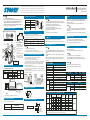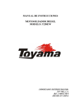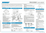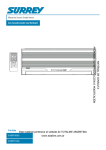
1
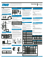
Los cables de una instalación eléctrica para interior y exterior deben ser cables flexibles forrados
de policloropreno (diseño H07RN-F) o cable denominado 245 IEC66. (La instalación debe ser realizada
Manual de Instalación
de acuerdo con las normas nacionales). Este manual de instalación es un extracto de los items re-
Aire Acondicionado tipo Multisplit
lacionados a la unidad exterior de un Acondicionador de Aire Multisplit, por favor referirse también
al manual de instalación de la unidad interior.
PRECAUCIÓN
POSICIÓN DE CONEXIÓN DE LA CAÑERÍA
• Esta unidad debe ser instalada por personal calificado únicamente.
• Desconecte la alimentación eléctrica principal y de las unidades interior y
exterior antes de efectuar cualquier trabajo eléctrico.
• Esta unidad exterior es provista con alimentación eléctrica individual.
• Asegúrese que todas las llaves de alimentación y de corte estén desconectadas. Cualquier descuido puede causar un shock eléctrico.
DIAGRAMA DE INSTALACIÓN DE LA UNIDAD EXTERIOR
Unidad exterior
Unidad A
538M3TFH2405
619MTFH1305
Unidad B
Unidad C
619MTFH0905
619MTFH0905
Unidad C
Unidad B
Unidad A
Aisle los caños de refrigerante individualmente
600 mm
TRABAJO ELÉCTRICO
Entrada de aire
340 mm
• Realice el cableado permitiendo una capacidad generosa.
1. La tensión de alimentación debe ser la misma que la tensión nominal del Aire
Acondicionado.
2. Prepare la alimentación para cada unidad.
3. La conexión eléctrica deberá contar de un interruptor general que posea una
separación entre contactos de por lo menos 3 mm.
Polietileno espumado resistente al calor de 6 mm de espesor
Salida de aire
Dirección del flujo de aire
600 mm o más
Hacia la unidad interior
1
m
00 m
ás
om
Montura
Extensión de la manguera
de drenaje (no disponible,
provista por el instalador)
100
o m mm
ás
Fijación de la unidad exterior
• Asegure la unidad exterior
con tornillos de fijación.
• Utilice tornillos de Ø 8 mm.
ó Ø 10 mm.
Tapa de partes
eléctricas
o
mm
600
má s
Distancias y diferencias de altura
538M3TFH2405
Corriente de
arranque
2
Tamaño de la tubería (mm)
Líquido
Gas
A
619MTFH1305
∅6.35
∅12.70
B
619MTFH0905
∅6.35
∅9.52
C
619MTFH0905
∅6.35
∅9.52
Largo máximo Desnivel máxima
de la cañería
entre unidades
(equivalente)
(equivalente)
10 m (L1)
15 m (L2 + L3)
5m
PURGA DE AIRE
FINALIZANDO
PRECAUCIÓN
1 Cuando la conexión de la línea de refrigerante, cableado entre unidades y
drenaje estén listos, envuelva con cinta de terminación las cañerías y conexiones.
2 Asegure la cañería encintada a la pared con grampas, etc.
• Nunca realice una purga de aire en los caños de conexión o en la unidad
exterior utilizando el refrigerante. Resultará en un daño. Utilice siempre una
bomba de vacío para evacuar el aire de los caños de conexión.
• Respete estos 4 puntos importantes para la instalación (cañería)
1- Elimine la suciedad y la humedad (del interior de los caños de conexión).
2- Apriete las conexiones (entre los caños y las unidades).
3- Evacúe el aire de los caños de conexión utilizando una bomba de vacío.
4- Verifique que no haya pérdidas de gas (puntos de conexión).
• Evacue el aire de cada una de las unidades interiores A, B y C.
1A
—
0.75 mm o más
—
50Hz, 220 – 240 V ~
Monofásico
15.9A
20A
2.0 mm2 o más
27A + 27A
ENTREGA A CLIENTES
H
L1
H
El fabricante se reserva el derecho de realizar cualquier modificación sin previo aviso.
L2
Cable de alimentación
PRECAUCIÓN
Unidad interior
A
Alimentación
Capacidad de refrigeración
(kW)
7.2
Corriente de funcionamiento
(A)
10.75
Consumo
(W)
2400
Factor de Potencia
(%)
98
Corriente de arranque
(A)
Cable de conexión
de la unidad interior C
Abrazadera
27 + 27
PELADO DEL CABLE DE ALIMENTACIÓN - PELADO DEL CABLE DE CONEXIÓN
60 mm
75 mm
10 mm
619MTFH0905
619MTFH1305
610
Ancho
(mm)
790
790
Alto
(mm)
275
275
Profundidad (mm)
208
208
630
∅6.35 x 3
∅12.7 x 1, ∅9.52 x 2
619MTFH0905
619MTFH0905
Unidad interior (kg)
Modelo unidad exterior
619MTFH1305
538M3TFH2405
Unidad exterior (kg)
Dimensión
69
538M3TFH2405
(m3/h)
Caudal de aire
10
Modelo
3470
Ancho
(mm)
880
Alto
(mm)
690
Profundidad (mm)
310
10 mm
Línea a tierra
Epecificaciones de performance para la combinación de unidades interiores
Estado de
funcionamiento
Alimentación
(V)
1 unidad
230
CANTIDADES ADICIONALES DE REFRIGERANTE
N
L
Carga – No se requiere carga de refrigerante adicional–
Carga por metro agregado
619MTFH0905
(m3/h)
Unidad C
• El largo mínimo de la cañería de refrigerante entre unidades debe ser 2 m.
Modelo
Dimensión
Conexión flare
Modelo
Cable de conexión
Cable de conexión
de la unidad interior A de la unidad interior B
Modelo unidad interior
Caudal de aire
R22 0.65 kg + 0.83 kg
Línea a
tierra
Peso neto
Nunca modifique el equipo removiendo alguno de los protectores de seguridad
o realizando un by-pass de alguno de los interruptores de seguridad.
–50Hz, 220 – 240 V ~ Monófasico
Lado del gas (mm)
Fusible o
llave de corte
1 Verifique que las válvulas estén abiertas antes de realizar el test.
2 Nunca fuerce un test de funcionamiento presionando el contactor magnético
(es extremadamente peligroso ya que el sistema de protección no será activado).
Multisplit
Tubería
Cable de
alimentación
PRECAUCIÓN
ADVERTENCIA
Tipo
Lado del líquido (mm)
*Siempre conecte el cable
de alimentación de la unidad exterior
a un fusible o llave de corte especial.
L3
• Debe realizarse un test de funcionamiento.
Refiérase al Manual del Usuario de la unidad interior para conocer la manera en
que debe realizarse.
ESPECIFICACIONES
Tipo de conexión
Unidad interior
B
Unidad exterior
TEST DE FUNCIONAMIENTO
PRECAUCIÓN
• Realice la aislación de la cañería de refrigerante en la línea de líquido y la línea
de gas de manera independiente.
• Cuando se enciende al acondicionador de aire para refrigerar el ambiente,
ambas cañerías (líquido y gas) se enfrían. Por ello ambas deben aislarse del
calor para evitar la condensación.
Cable de
conexión
Unidad B
• No olvide entregar a cada cliente el Manual del Propietario.
• Tómese el tiempo y el esfuerzo de explicar los contenidos de las instrucciones
a cada cliente cuando entrega el acondicionador de aire.
Verifique que no haya pérdidas de gas en las conexiones de la cañería y válvulas. Utilice siempre refrigerante (R-22) para verificar pérdidas en las conexiones de la cañería.
• Utilice el tubo de aislación provisto para la cañería de conexión en la unidad
interior ya que este es provisto sin que quede espacio libre entre ellos.
• Conecte el cable de alimentación y el cable de conexión como se muestra en la siguiente figura.
• Cada unidad interior y exterior necesita un cable de alimentación.
1. Remueva la tapa de las partes eléctricas de la unidad exterior (4 tornillos).
2. Conecte el cable de alimentación y el cable de conexión a los terminales identificados con
los respectivos números en los bloques de terminales de las unidades interior y exterior.
(Pele los cables con los largos indicados e insértelos completamente en el bloque de terminales).
3. Cuando el cable de alimentación y el cable de conexión estén conectados a los terminales
de la unidad exterior, deje un excedente (rulo) como se muestra en el diagrama de instalación de la unidad exterior, para prevenir el ingreso de agua a la unidad.
4. Aisle los cables no utilizados (conductores) con cinta aisladora. Asegúrese que los mismos no toquen ninguna parte eléctrica o metálica.
Unidad interior
C
No permita que los cables (tanto los de alimentación como los de interconexión de unidades) estén en contacto con las válvulas de refrigeración o
cañería no cubierta con aislación.
Asegure los cables con los tramos de cañería provistos con aislación de calor.
VERIFICACIÓN DE PÉRDIDAS DE GAS
Refrigerante
Unidad A
PRECAUCIÓN
ABRA COMPLETAMENTE LAS VÁLVULAS / Aislación de calor
—
CÓMO CONECTAR LOS CABLES DE ALIMENTACIÓN Y DE CONEXIÓN
CAÑERÍA DE CONEXIÓN DE REFRIGERANTE
Unidad interior
Cableado
• Utilice la tensión especificada en la tabla de arriba.
• Realice el circuito para cada unidad con fuentes de alimentación independientes.
• No mezcle los cables y los caños de conexión de las unidades interior y exterior.
Realice un bucle con el
excedente de cable
(aprox.100 mm de diámetro
y 300 - 350 mm de largo)
Unidad exterior
Corriente máxima Fusible
de arranque
(Amp.)
Alimentación
PRECAUCIÓN
600
o m mm
ás
Modelo
Modelo
Sección
Cable de
—
conexión
Cable de
538M3TFH2405
alimentación
(Unidad exterior)
Unidad exterior 538M3TFH2405
Unidad interior 619MTFH0905
619MTFH1305
10 mm
45 mm
538M3TFH2405
No se necesita
3
2
1
Cable de alimentación
10 mm
65 mm
Cable de conexión
Para unidades interiores A, B, C
Capacidad
(kW)
Unidad interior
A
B
C
A
13
–
–
–
10
–
–
–
13
Capacidad de
enfriamiento
(kW)
Corriente de
funcionamiento
(A)
Consumo (W)
B
C
3.4
–
–
3.4
5.55
1240
–
2.8
–
2.8
5.45
1220
10
–
–
2.8
2.8
5.45
1220
10
–
3.4
2.8
–
6.2
10.30
2300
3.4
–
2.8
6.2
10.30
2300
2 unidades
230
13
–
10
–
10
10
–
1.9
1.9
3.8
6.00
1340
3 unidades
230
13
10
10
3.4
1.9
1.9
7.2
10.75
2400
Modelo
538M3TFH2405
• Los valores arriba especificados se refieren a espacios interiores con temperaturas entre 27/19º (bulbo seco/bulbo húmedo) y exterior
de 35º (bulbo seco) a 230 v.
• El fabricante se reserva el derecho de realizar cualquier modificación sin previo aviso.
1105607501 / 538M3TFH-24-00IM
Power supply cord of parts of appliance for indoor and outdoor use should be more than polychloroprene
sheathed flexible cord (design H07RN-F) or cord designation 245 IEC66. (The appliance shall be installed in
Installation Manual
accordance with national regulations.) This installation manual is an extract of the items related to the outdoor
Air Conditioner Multisplit type
unit of MULTI SPLIT AIR CONDITIONER only, please refer to the installation manual of the indoor unit as well.
DANGER
REFRIGERANT PIPE CONNECTING POSITION
• FOR USE BY QUALIFIED PERSONS ONLY.
• TURN OFF A MAIN POWER SUPPLY SWITCH AND A BREAKER OF THE OUT
DOOR AND INDOOR UNITS BEFORE ATTEMPTING ANY ELECTRICAL WORK.
• INDIVIDUAL POWER SUPPLY IS PROVIDED IN THIS OUTDOOR UNIT.
• MAKE SURE ALL POWER SWITCHES AND THE BREAKER ARE TURNED OFF.
FAILURE TO DO SO MAY CAUSE ELECTRIC SHOCK.
INSTALLATION DIAGRAM OF OUTDOOR UNIT
Outdoor unit
Unit A
538M3TFH2405
619MTFH1305
Unit B
Unit C
619MTFH0905
619MTFH0905
Unit C
Unit B
Unit A
Insulation of refrigerant pipes insulate the pipes separately.
34 0 m m
• Perform wiring work so as to allow a generous wiring capacity.
1. The supply voltage must be the same as the rated voltage of the air conditioner.
2. Prepare the power source for each unit.
6 mm thick heat resisting polyethylene foam
600 mm or more
re
r mo
Saddle
o
mm
100
Extension drain hose
(Not available,
provided by installer)
100
or m mm
ore
Electric parts
cover
6 00
mm
ore
or m
600
or m mm
ore
Anchor bolt arrangement
of the outdoor unit
• Secure the outdoor unit with
the anchor bolts if the unit is
likely to be exposed to a strong
wind.
• Use Ø8 mm or Ø10 mm
anchor bolts.
• If it is necessary to drain use
the service parts drain nipple
to the bottom plate of the outdoor unit before installing it.
Loop the connecting cable
(about 100 mm in diameter
and 300 – 350 mm long).
REFRIGERANT PIPING CONNECTION
Permissible Piping Length and Head
Model
Outdoor Unit
Indoor Unit
Liquid
Gas
Permissible
piping length
10 m (L1)
A
619MTFH1305
∅6.35
∅12.70
B
619MTFH0905
∅6.35
∅9.52
C
619MTFH0905
∅6.35
∅9.52
Permissible
piping head (H)
15 m (L2 + L3)
5m
Power cord
(outdoor unit)
Maximum
running current
Power supply
Fuse
rating
Wiring
2
Starting
current
—
—
1A
—
0.75 mm or more
—
538M3TFH2405
50Hz, 220 – 240 V ~
Single phase
15.9A
20A
2.0 mm2 or more
27A + 27A
1. When the connection for the refrigerant piping, wiring between the indoor
and outdoor units, and drain piping are completed, wrap finishing tape around
the pipes and connections.
2. Secure the taped pipes and connections to the wall with clamps, etc.
• Never carry out air purge which utilizes the refrigerant of the unit. It will
result in damage. Always use a vacuum pump to evacuate air from connecting pipes.
• Keep important 4 points for installation (piping work).
1. Take away dust and moisture (inside of the connecting pipies)
2. Tight connection (between pipes and unit)
3. Evacuate the air in the connecting pipes using VACUUM PUMP.
4. Check gas leak (Connected points)
DANGER
Do not allow the cables (used for the power supply and for wiring between the
units) to come into contact with the refrigerant valves or pipes not covered
with insulators.
Secure these cables to the parts of the pipes provided with the heat insulators.
HOW TO CONNECT THE POWER CORD AND THE CONNECTING CABLE
• Connect the power cord and the connecting cable as the following figure.
• Each indoor and outdoor units need the power cords.
1. Remove the electric parts cover from the outdoor unit (4 screws).
2. Connect the power cord and the connecting cable to the terminals as identified with their
respective matched numbers on the terminal block of indoor and outdoor units. (Strip the
sheath of the power cord and the connecting cable as the following stripping length and
insert them fully into the terminal block.)
3. When the power cord and the connecting cable are connected to the terminals of the outdoor unit, make a loop as shown in the installation diagram of the outdoor unit, to prevent
water coming in the outdoor unit.
4. Insulate the unused cords (conductors) with a PVC tape. Proceed them so that they do not
touch any electrical or metal parts.
Indoor unit
C
Indoor unit
B
FULLY OPEN THE VALVES / Heat Insulation
Fuse or
breaker
Power cord
Unit B
Connecting cable
of indoor unit C
Cord clamp
Connecting cable
of indoor unit A
Type
(kW)
Running current
(A)
10.75
Power Consumption
(W)
2400
Power factor
(%)
98
Starting current
(A)
27 + 27
7.2
60 mm
Dimension
Flare connection
Indoor unit
619MTFH0905
619MTFH0905
619MTFH1305
(m3/h)
610
Width
(mm)
790
790
Height
(mm)
275
275
Depth
(mm)
208
208
630
∅6.35 x 3
Liquid side (mm)
∅12.7 x 1, ∅9.52 x 2
(mm)
Model
Net weight
Indoor Unit Model
Air flow rate
R22 0.65 kg + 0.83 kg
Gas side
L2
H
–50Hz, 220 – 240 V ~ Single phase
Cooling capacity
Pipe
Never modify this machine by removing any of the safety
guards or by by-passing any of the safety interlock switches.
Multi Split Type
Power suppl
Connecting cable
of indoor unit B
STRIPPING LENGHT OF THE POWER CORD
1. Check that the valves are open before starting a test run.
2. Never forcibly conduct a test run by pressing the magnetic contactor.
(This is extremely dangerous since the protection device will not be activated.)
WARNING
Connecting type
Power cord
DANGER
SPECIFICATIONS
Earth line
* Always connect the power cord of the
outdoor unit to a special fuse or breaker.
A test run must be carried out.
Refer to the indoor unit Owner’s Manual for the procedure involved.
• Use the heat insulating pipe supplied for the piping connecting section on the
indoor unit side so that heat insulation can be provided without leaving a gap in
between.
• Provide heat insulation at the refrigerant piping on the liquid side and gas side
separately.
• When the air conditioner is turned on to cool the room, both the liquid side
and gas side become cold, so they must be insulated from heat to prevent
condensation.
Refrigerant
Indoor unit
A
Outdoor unit
Unit C
• Do not forget to provide each customer with the Owner’s Manual.
• Take the time and effort to explain thoroughly the contents of these instructions to each customer when delivering the air conditioner.
Check for gas leaks from the piping connections and valve caps.
Always use the refrigerant (R22) to check for leaks from the piping connections.
TEST RUN
• Use the power as specified in the above table.
• Use the circuit set up for each unit for separated power source.
• Do not mingle the wires and the pipes connected to the indoor and the outdoor units.
L3
DELIVERY TO COSTUMERS
DANGER
Connecting
cable
Unit A
H
DANGER
GAS LEAK CHECK
DANGER
L1
The manufacturer reserves the right to modify any product characteristics without prior notice.
538M3TFH2405
Piping size (mm)
Model
Section
Connecting
cable
Air outlet
Airflow director
FINISHING
• Evacuate the air for each indoor unit A and B + C.
Air inlet
To the indoor unit
AIR PLUGING
ELECTRICAL WORK
600 mm
Outdoor Unit 538M3TFH2405
Indoor Unit 619MTFH0905
619MTFH1305
619MTFH0905
619MTFH0905
(kg)
Outdoor Unit Model
619MTFH1305
10
Model
538M3TFH2405
Outdoor unit (kg)
69
Dimension
538M3TFH2405
(m3/h)
Air flow rate
3470
Width
(mm)
880
Height
(mm)
690
Depth
(mm)
310
10 mm
Performance Specifications for Combination of Indoor Unit
DANGER
N
L
• The minimum inter-unit refrigerant piping length shall be 2 m.
10 mm
45 mm
Operating
status
Power
supply
(V)
1 unit
230
Power cord
ADDITIONAL REFRIGERANT QUANTITIES
STRIPPING LENGHT OF THE CONNECTING CABLE
Chargeless – No additional refrigerant requires –
Unit capacity
(kW)
B
C
Cooling
capacity
(kW)
3.4
–
–
3.4
5.55
1240
–
2.8
–
2.8
5.45
1220
10
–
–
2.8
2.8
5.45
1220
10
–
3.4
2.8
–
6.2
10.30
2300
3.4
–
2.8
6.2
10.30
2300
Indoor unit
A
B
C
A
13
–
–
–
10
–
–
–
13
Operation
current
(A)
Power
consumption
(W)
Model
75 mm
10 mm
Model
538M3TFH2405
Addition per meter
No need
For indoor unit A, B, C
Earth line
3
2
1
10 mm
65 mm
Connecting cable
2 unit
230
13
–
10
–
10
10
–
1.9
1.9
3.8
6.00
1340
3 unit
230
13
10
10
3.4
1.9
1.9
7.2
10.75
2400
538M3TFH2405
• The above specification values assume indoor dry-bulb/wet-bulb temperature of 27/19°C and outdoor dry-bulb temperature of 35°C at
230 V.
• The specification may be subject to change without notice for purpose of improvement.
1105607501 / 538M3TFH-24-00IM