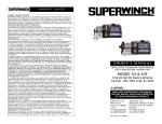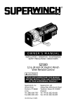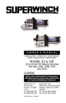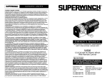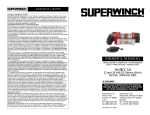
1
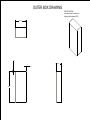
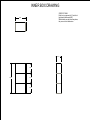
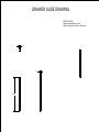
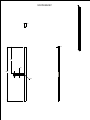
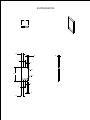
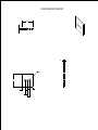
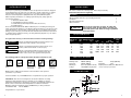
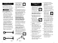
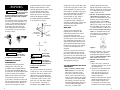
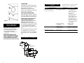
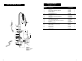
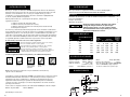
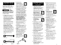
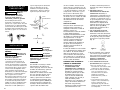
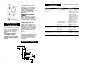
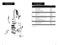
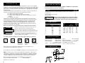
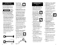
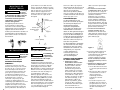
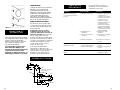
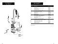
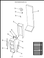
Cabinet Exploded Assembly View
2
1
3
4
5
6
7
8
9
8
9
9
9
10
SCALE
0.100
Wall and Countertop
1
Winch
2
Pulley
3
Limit Switch
4
Outer Box
5
Cable Bracket
6
Mounting Bracket
7
Inner Mounting Bracket Plate
8
Drawer Slide
9
Outer Box Cabinet
10
OUTER BOX DRAWING
SPECIFICATIONS:
All material used to make box is
high density fiberboard (HDF).
25.00
.50
13.00
.50
39.75
INNER BOX DRAWING
SPECIFICATIONS:
Entire box is composed of 1/2 inch thick
high-density fiberboard (HDF).
Middle shelves can be placed anywhere;
they are not critical dimensions.
23.00
12.50
12.25
38.75
12.75
12.25
DRAWER SLIDE DRAWING
SPECIFICATIONS:
Standard drawer slides are used.
Minimum rating for each slide is 100lbs max.
1.50
.50
22.00
MOUNTING BRACKET
1.75
.25
11.00
.50
23.00
.50
R.15
MOUNTING BRACKET SIDE
1.75
.38
.38
.50
.50
R.05
2.00
R.15
.50
.50
.38
.38
.25
MOUNTING BRACKET BRACKET
2.50
.25
.25
R.15
1.75
.75
.75
.50
.50
GARANTIE LIMITÉE
GARANTIE LIMITÉE
Superwinch Inc. (« Vendeur » ou « Superwinch ») garantit à l'acheteur au détail original seulement
(« Acheteur ») que tous les produits, pièces et composants Superwinch originaux, sauf les câbles
métalliques et accessoires (« Produits ») seront libres de défauts de matériaux et de main d'œuvre
pendant une période d'UN (1) an de la date prouvable d'achat d'un nouveau Produit. Tout Produit
qui, de l'avis de Superwinch s'avère défectueux sera réparé ou remplacé à la seule discrétion de
Superwinch sans frais pour l'Acheteur suite à la conformité de l'Acheteur avec ces procédures.
Le Vendeur ou son Agent autorisé peut facturer tous frais raisonnables pour les pièces et la main
d'œuvre pour les réparations non couvertes par cette Garantie limitée. Les garanties indiquées dans
ce document sont exclusives et remplacent toutes autres garanties, orales ou écrites, expresses ou
implicites.
PROCÉDURE DE GARANTIE LIMITÉE
En contactant le Vendeur, l'Acheteur postera, expédiera ou livrera de quelque autre façon à l'adresse
indiquée plus bas ou à un centre de service autorisé de l'usine : (1) le Produit; (2) une description
écrite du problème; (3) le nom de l'Acheteur, son adresse et son numéro de téléphone; et (4) une
copie du reçu de vente original. Postez, expédiez ou livrez de toute autre façon le Produit,
l'information requise et les copies au Vendeur, à frais d'affranchissement ou d'expédition prépayés.
LIMITES ET EXCLUSIONS
La réparation et/ou le remplacement du Produit est à la seule discrétion et est le seul recours de
l'Acheteur. Cette garantie ne s'applique pas aux défauts de tout Produit causés par : (1) l'usure
normale; (2) une non-conformité à toutes instructions d'installation, d'opération ou de maintenance
fournies par Superwinch y compris, mais sans s'y limiter, soumettre le Produit à des charges dépassant
la charge indiquée dans le Mode d’Emploi ou dans les instructions pour le Produit en particulier ainsi
que le numéro de modèle; (3) l'utilisation commerciale ou industrielle; (4) l'altération ou la
modification par des parties autres que Superwinch; (5) la mauvaise utilisation, l'abus, la négligence,
les accidents, les forces majeures ou le terrorisme; ou (6) d'autres causes hors du contrôle de
Superwinch après la livraison du Produit par Superwinch à son distributeur autorisé. Si tout modèle
ou échantillon a été montré à l'Acheteur, un tel modèle ou échantillon a été utilisé à des fins
d'illustration seulement et ne sera pas considéré comme une garantie que le Produit sera conforme
à l'échantillon ou au modèle.
OWNER’S MANUAL
INSTALLATION • OPERATION • MAINTENANCE
SAFETY PRECAUTIONS • REPAIR PARTS
DANS LA PLEINE MESURE PERMISE PAR LA LOI APPLICABLE, CE QUI SUIT EST PAR LA PRÉSENTE
EXCLUS ET RÉFUTÉ :
(1) Toutes les garanties quant au câble métallique, vendu seul ou utilisé dans ou incorporé dans
tout produit.
AC1000
(2) Toutes les garanties quant au fini du Produit.
(3) Toutes les garanties d'adaptabilité à un besoin particulier.
115V AC Electric Winch
Model AC1000
Part No. 1401
(4) Toutes les garanties de commerciabilité.
(5) Toutes les réclamations de dommages consécutifs ou indirects.
Certains états ou juridictions ne permettent pas de limites ou d'exclusions de transactions pour les
clients et ces limites ou exclusions pourraient ne pas s'appliquer à l'Acheteur. La garantie donne à
l'Acheteur des droits juridiques précis et il pourrait y en avoir d'autres. Si une garantie est considérée
appliquée à ce Produit, elle n'existera seulement que pour la même période que celle établie dans la
garantie limitée expresse indiquée précédemment. AUCUN agent, concessionnaire, distributeur ou
employé du Vendeur n'est autorisé à apporter des modifications à cette garantie et aucune
déclaration de ce genre, orale ou écrite ne liera le Vendeur.
QUESTIONS
Toutes questions portant sur la conformité des garanties fournies dans ce document peuvent être
adressées par écrit à Superwinch Inc. ou à Superwinch, Ltd. aux adresses indiquées plus bas.
Superwinch, Inc.
Winch Drive
Putnam, CT 06260
U.S.A.
Tel. (860) 928-7787
Fax (860) 963-0811
Superwinch, Ltd.
Abbey Rise, Whitchurch Road
Tavistock, Devon PL 19 9DR
England
Tel. +44 (0) 1822 614101
Fax +44 (0) 1822 615204
!
CAUTION
READ AND UNDERSTAND THIS MANUAL BEFORE INSTALLATION
AND OPERATION OF YOUR SUPERWINCH PRODUCT.
Superwinch, Inc.
Winch Drive
Putnam, CT 06260
U.S.A.
Tel. (860) 928-7787
Fax (860) 963-0811
90-12841 Rev - 7/29/05
Superwinch, Ltd.
Abbey Rise, Whitchurch Road
Tavistock, Devon PL 19 9DR
England
Tel. +44 (0) 1822 614101
Fax +44 (0) 1822 615204
INTRODUCTION
U N PA C K I N G
Thank you for purchasing an AC1000 winch from Superwinch. It has been designed
and manufactured to provide years of trouble-free operation. We hope you will be
pleased with its performance. If you are not, for any reason, please contact our
Customer Service Department: (860) 928-7787 USA; (1822) 614101 England.
When requesting information or ordering replacement parts; always give the
following information:
1. Winch Part Number 1401
2. Serial Number (found on housing)
3. Part Number (found in Replacement Parts List section)
4. Part Description
Please read and understand this Owner’s Manual prior to installing and using your
winch. Pay particular attention to the General Safety Information. Your winch is a very
powerful machine. If used unsafely or improperly, there is a possibility that property
damage or personal injury can result. We have included several features in this winch
to minimize this possibility; however, your safety ultimately depends on your caution
when using this product.
Throughout this manual, you will find notations with the following headings:
DANGER
Indicates an imminently hazardous situation which, if not
avoided, will result in death or serious injury.
!
WARNING
Indicates a potentially hazardous situation which, if not
avoided, could result in death or serious injury.
!
CAUTION
Indicates a potentially hazardous situation which, if not
avoided, may result in minor or moderate injury. This
notation is also used to alert against unsafe practices.
!
The following symbols on the product and in the Owner's manual are used:
Read Owner's
Manual
Always Use
Handsaver
Keep clear of winch,
wire rope and hook
while operating
Never use winch
to lift or move
people
Never use
winch to hold
loads in place
This carton contains the following items. Please unpack carefully.
Read instructions before beginning.
Description
Quantity
Winch assembly with wire rope including lead wires
Handsaver
Mounting hardware kit
Owner’s manual
!
1
1
1
1
Risk of electric shock. Do not open. To reduce the
risk of electric shock, do not remove cover. No user
serviceable parts inside. Refer servicing to qualified
service personnel.
CAUTION
PERFORMANCE
Wire Rope
Layer
Max. Pulling Capacity
lbs.
kg
1
2
3
4
5
6
1,000
875
800
700
625
550
454
397
363
317
283
249
Load*
lbs.
kg
0
250
500
750
1,000
0
113
227
340
454
Motor Current
Amps
Speed
ft/min m/min
115V
23.0
19.0
17.0
15.0
13.0
7.0
5.8
5.2
4.6
4.0
3.0
5.0
7.0
8.0
10.0
S P E C I F I C AT I O N S
Working Load*
Stall Load*
Wire Rope*
Voltage
1000 lbs. (454 kg)
1500 lbs. (680 kg)
5/32” x 45’ (3.9mm x 13.7m)
115V, 50/60 hz, single phase
Motor
0.6 hp (0.45 KW)
Gear Ratio
123:1
Duty Cycle 20 secs. ON, 1/2 hr. OFF, full load
* Based on first layer performance
DIMENSIONS
Note: Indicates additional information in the installation and operation
procedures of your winch.
13.38"
Correct installation of your AC1000 winch is a requirement for proper operation.
(340mm)
*2.13"
(54mm)
Please Note: This winch is not designed to be used in industrial or hoisting
applications and Superwinch does not warrant it to be suitable for such use.
Superwinch manufactures a separate line of winches for industrial/commercial use.
Please contact our Customer Service Department for further information.
Note the electrical requirements of the AC1000 winch you have purchased.:
Part Number 1401
115 Volt 50/60Hz
*3.69"*
(94mm)
*1.20"(30mm)
5.69"
Congratulations on your choice!
(145mm)
2.94"
(75mm)
5.38"
(137mm)
2
3
GENERAL SAFETY
I N F O R M AT I O N
Your AC1000 winch is a very
powerful machine. Treat it with
respect, use it with caution and
always follow these safety guidelines.
The wire rope
may break
before the winch stalls. For heavy
loads, use a pulley block to reduce
the load on the wire rope.
!
WARNING
1. The AC1000 winch is rated at
1,000 pounds (454 kg) (single
line) capacity on the wire rope
layer closest to the drum. DO
NOT OVERLOAD. DO NOT
ATTEMPT PROLONGED PULLS AT
HEAVY LOADS. Do not maintain
power to the winch if the motor
stalls. Overloads can damage the
winch and/or the wire rope and
create unsafe operating
conditions. FOR LOADS OVER
750 POUNDS (340 KG), WE
RECOMMEND THE USE OF THE
OPTIONAL PULLEY BLOCK TO
DOUBLE LINE THE WIRE ROPE
(Figure 2). This reduces the load
on the winch and the strain on
the wire rope by approximately
50%. Do not hook back to winch.
Always hook onto structure
capable of supporting load.
Load
Winch
Single line
2. AFTER READING AND
UNDERSTANDING THIS
MANUAL, LEARN TO
USE YOUR WINCH.
After installing the winch,
practice using it so you will be
familiar with it when the need
arises.
3. KEEP WINCHING AREA CLEAR. Do
not allow people to remain in the
area during winching operations.
ALWAYS STAND CLEAR OF WIRE
ROPE, HOOK AND WINCH. IN THE
UNLIKELY EVENT OF ANY
COMPONENT FAILURE IT IS BEST
TO BE OUT OF HARM‘S WAY.
4. INSPECT WIRE ROPE AND
EQUIPMENT FREQUENTLY. A
FRAYED WIRE ROPE WITH
BROKEN STRANDS SHOULD
BE REPLACED IMMEDIATELY.
Always replace wire rope with
the manufacturer‘s identical
replacement part (see Replacement
Parts List). Periodically check the
winch installation to ensure that
all bolts are tight.
5. USE HEAVY LEATHER GLOVES
when handling wire rope.
DO NOT LET WIRE ROPE SLIDE
THROUGH YOUR HANDS EVEN
WHEN WEARING GLOVES.
6. NEVER WINCH WITH LESS THAN 5
TURNS of wire rope AROUND THE
WINCH DRUM since the wire rope
end fastener will NOT withstand
a load. ALWAYS USE
THE HANDSAVER when
guiding the wire rope
in or out (see Figure 3).
Anchor Point
Pulley Block
Load
1/2 Load
Approx.
Approx. 1/2 Load
Winch
GENERAL SAFETY
I N F O R M AT I O N
( C O N T. )
7. KEEP CLEAR OF WINCH, TAUT
WIRE ROPE AND HOOK WHEN
OPERATING WINCH.
Never put your finger
through the hook. If
your finger should
become trapped in the hook,
you could lose your finger.
Never guide a wire rope onto
the drum with your hand.
8. NEVER HOOK THE WIRE ROPE
BACK ONTO ITSELF because you
could damage the wire rope.
Use a nylon sling.
9. NEVER USE YOUR
WINCH FOR HOISTING
APPLICATIONS OR FOR
LIFTING OR MOVING PEOPLE.
10. Your winch is not designed or
intended for overhead hoisting
operations.
11. AVOID CONTINUOUS PULLS
FROM EXTREME ANGLES as this
will cause the wire rope to pile
up at one end of the drum. This
can jam the wire rope in the
winch, causing damage to the
rope or the winch.
12. NEVER OBSCURE THE WARNING
INSTRUCTION LABELS.
13. Always operate winch with an
unobstructed view of the
winching operation.
14. Equipment such as tackle, hooks,
pulley blocks, straps, etc. should
be sized to the winching task
and should be periodically
inspected for damage that could
reduce their strength.
15. DO NOT OPERATE WINCH
WHEN UNDER THE INFLUENCE
OF DRUGS, ALCOHOL OR
MEDICATION.
16. When moving a load, slowly
take up the wire rope slack until
it becomes taut. Stop, recheck
all winching connections. Be
sure the hook is properly seated.
If a nylon sling is used, check the
attachment to the load.
17. DO NOT USE THE
WINCH TO HOLD
LOADS IN PLACE.
Use other means of
securing loads such as tie down
straps. Superwinch offers a wide
variety of tie downs. Contact
your local Superwinch dealer.
18. USE ONLY FACTORY APPROVED
SWITCHES, REMOTE CONTROLS
AND ACCESSORIES. Use of nonfactory approved components
may cause injury or property
damage and could void your
warranty.
19. DO NOT MACHINE OR WELD
ANY PART OF THE WINCH. Such
alterations may weaken the
structural integrity of the winch
and could void your warranty.
20. Never allow shock loads to be
applied to winch or wire rope.
21. Use caution when pulling or
lowering a load up and down
a ramp or incline. Keep people,
pets and property clear of the
path of the load.
22. BE SURE that the power supply
is disconnected before
performing maintenance
or repair procedures.
Double line
Figure 2
4
Figure 3
5
MOUNTING
YOUR WINCH
This winch MUST
be mounted with
the wire rope in the underwind
direction. Improper mounting could
damage your winch and void your
warranty.
!
WARNING
This unit may be mounted in either
a horizontal or vertical position, on
a wall or other suitable support. In
all installations, the unit must be
mounted so that the wire rope
feeds perpendicular to the drum
axis and does not rub across the
housing or base.
premature failure of the internal
bridge rectifier. Drill two 7/16"
(12mm) diameter holes with centers
3 11/16" (94mm) apart in the
support choosen for the winch.
Attach the winch to the support
with the mounting hardwar
provided. Tighten the hardware
to 35 pound foot torque.
Bolt
Flat Washer
WIRE ROPE
Flat Washer
Lock Washer
Nut
Support
3 11/16" (94mm)
I N S TA L L AT I O N
DO NOT
! WARNING
operate this
winch outdoors or in a corrosive
or explosive environment.
MINIMUM ELECTRICAL
REQUIREMENTS
The three-prong plug must be
plugged into a 115 Volt, AC
grounded outlet equipped with a
ground fault interrupter (GFI). Do
not plug into an ungrounded outlet
by using a three prong adapter.
Make sure that the power supply
and reversing switch cords are
positioned so that the moving load
will not damage them. Unplug the
winch when not in use. Electrical
storms or line surges can cause
6
single line for 20 seconds “On” time
on the wire rope layer closest to the
drum. Attempts to pull more than
this weight or exceed the duty cycle
may cause damage to the winch or
wire rope and could cause the
circuit breaker to trip, and the
winch will not operate. (See
“Trouble Shooting”.) Maintain a
minimum of five wraps of wire rope
around the winch drum before
attempting any pulls.
Do not substitute any
strength grade weaker than ISO
grade 5.
!
WARNING
The switch
assembly must
be kept free of dirt and moisture
to ensure safe operation.
!
CAUTION
OPERATION
This unit is activated via the switch
at the six foot cord. To remove wire
rope from the winch, depress the
“Out” button. The load will stop
without coasting when the button
is released. To pull a load or spool
wire rope onto the drum, depress
the “In” button. Your winch is
designed to pull 1,000 pounds in
A part of your winch that will
require periodic attention and
eventual replacement is the wire
rope. Inspect the wire rope
frequently. If fraying exists, replace
the wire rope at once. Your winch
uses galvanized aircraft type 7 x 19
cable. Always replace the wire rope
with Superwinch replacement rope,
P/N 1527. Because all rope is subject
to wear, it is excluded from our
warranty.
The wire rope has been installed on
your winch under minimal load at
the factory. The wire rope must be
respooled onto the drum under load
so that the outer layers will not draw
down into the inner ones thereby
damaging the wire rope.
TIPS FOR EXTENDING THE LIFE OF
YOUR WINCH
1. KEEP A TIGHTLY WOUND WIRE
ROPE DRUM. Do not allow the
wire rope to become loosely
wound. A loosely-wound spool
allows a wire rope under load to
work its way down into the layers
of wire rope on the drum. When
this happens, the wire rope may
become wedged within the body
of the windings damaging the
wire rope. To prevent this
problem, keep the wire rope
tightly and evenly wound on the
drum at all times. A good practice
is to rewind the wire rope under
tension after each use.
2. DO NOT ALLOW WINCH MOTOR
TO OVERHEAT. Remember, the
winch is for intermittent use only.
During long or heavy pulls the
motor will get hot. At 1,000 lb.
(454 kg) allow motor to cool after
20 seconds of “On” time. At loads
less than 500 lb. (227 kg) allow to
cool after 2 minutes of “On” time.
3. USE A PULLEY BLOCK FOR HEAVY
LOADS. To maximize winch and
wire rope life, use a pulley block
to double line heavier loads
(Figure 8).
Figure 8
4. The pull required to start a load
moving is often much greater
than the pull required to keep it
moving. AVOID FREQUENT STOPS
AND STARTS during pull.
5. PREVENT KINKS BEFORE THEY
OCCUR.
a. This is the start of a kink. At
this time, the wire rope should
be straightened.
b. The wire rope was pulled and
the loop has tightened to a
kink. The wire rope is now
permanently damaged and
must be replaced.
c. Kinking causes the wire strands
under the greatest tension to
break and thus reduces the
load capacity of the wire rope.
The wire rope must be replaced.
7
LUBRICATION
The gearbox and drum bearing are
permanently lubricated with a high
performance gear lube. If
relubrication is necessary (after
repair or disassembly) only use Shell
Alvenia EP2 or equivalent.
a
TROUBLESHOOTING
CHART
Symptom
Motor will not operate or
runs in one direction only
If a problem arises, contact your nearest
Superwinch dealer or repair center.
Possible Cause(s)
Corrective Action
1. Circuit breaker tripped
1. Reset Circuit Breaker.
If the winch fails to
operate, the end of the
motor should be
checked. If
the circuit breaker has
tripped, this will be
indicated by the center
portion of the breaker
protruding from the
main body. To reset the
breaker, merely press the
center portion back into
the assembly.
2. Replace switch
3. Check for poor
connections.
4. Replace or repair motor
1. Allow to cool
2. Replace or repair motor
REPLACING THE WIRE ROPE
Never substitute a heavier or lighter
wire rope. Never use rope made of
any other material other than wire.
b
Always replace damaged wire
rope with manufacturer’s
identical replacement part (See
Replacement Parts list). Pass
attaching end of wire rope through
the fairlead (if equipped) and attach
it to the drum with the retainer
provided with the replacement wire
rope.
c
Figure 9
MAINTENANCE
A N D R E PA I R S
Periodically check tightness of
mounting bolts and electrical
connections. Remove any dirt or
corrosion that may have
accumulated on the electrical
connections.
Repair should be done by
Authorized Superwinch Repair
Centers ONLY. Do not attempt
to disassemble the gearbox.
Disassembly will void warranty.
It is important that the wire rope be
wound tightly onto the drum. A
good way to do this is to attach the
wire rope hook to a load and winch
it in.
Motor runs extremely hot
Winch will not hold load
2. Switch inoperative
3. Broken wires or bad
connection
4. Damaged motor
1. Long period of operation
2. Damaged motor
1. Excessive load
1. Reduce load or double
line
E L E C T R I C A L S C H E M AT I C
BLK
L
7A
115V
50 / 60 Hz
WHT
RED
WHT
N
SWITCHES SHOWN IN
OFF POSITION
ORA
BLU
CABLE IN
WHT
MOTOR
CABLE OUT
BLK
GRN
(GRN/YEL)
8
9
REPLACEMENT
PA R T S L I S T
10
19
27
27
24 23
22
R E P L A C E M E N T PA R T S
Part Number
Handsaver
Drum Assembly with Flange attached
Perimeter Bearing
Carrier Bearing
Planetary Gear Assembly
Nylon Step Washer
10 Tooth Sun Gear
Flat Washer
115V AC Motor w/ Control & Stationary
Flat Washer
Bushing
5/16" Socket Head Cap Screw
Pair 3/8" Bolts & Nuts, 4 Flat & 2 Lock Washers
Base Plate
Switch Assembly Only
Cable Tension Plate Set
5/32" x 45' Cable & Hook Assembly
Cable In Label
Cable Out Label
Warning Label
Bridge Rectifier
87-31120
90-32038
90-23137
90-23140
90-23138
90-12418
90-22865
90-23120-08
90-33345-04
90-23120-05
90-12174
90-23056-02
90-22892
90-41019BLK
90-23127
90-12450
1527
90-10517
90-10518
90-10516
90-10876
1
1
2
1
1
1
1
1
1
1
1
1
1
1
1
1
1
1
1
2
1
21
∆ Not Shown
12 13
14
6 5 7 8 9
5
Description
1
3
4
5
6
7
8
9
10
12
13
14
15
16
19
21
22
23
24
27
∆
15
16
2 4
1
Reference
Number
10
11
W A R R A N T Y R E PA I R C E N T E R S
USA
Superwinch Inc.
Winch Drive
Putnam, CT 06260
phone: 860-928-7787
[email protected]
Electric Motor Repair
2010 North 4th Street
Minneapolis, MN 55411
phone: 612-588-4693
Berens & Associates
124 Hegenberger Loop
Oakland, CA 94621
phone: 800-540-2858
[email protected]
Zorko’s Alternator Service
241 Wells Road
Home, PA 15747
phone: 800-468-5055
[email protected]
Electric Motors of Iowa City
50 Commercial Court
Iowa City, IA 52246
phone: 319-354-4040
[email protected]
Outdoors Plus
128 Regional St.
P.O. Box 1349
Port Aux Basques, NF A0M 1C0
709-695-7533
Bobcaygeon Auto and Marine
91 Main St.
Bobcaygeon, Ont. K0M 1A0
705-738-2317
MAP Bracebridge
19 Taylor Rd.
Bracebridge, Ont. P1L 1W3
705-645-8785
MAP Fenelon Falls
165 Lindsay St.
Fenelon Falls, Ont. K0M 1N0
705-887-6232
Central Electric Motor Rewind
#1-1960 Windsor Rd.
Kelowna, NC V1Y 2Y3
250-860-4415
[email protected]
CANADA
Delta Tool Repair Limited
114-7533, 135th St.
Surrey, BC V3W 0N6
604-591-3230
Demand Electric
228-39th St. N.E.
Calgary, AB T2E 2M5
403-230-2709
Ted's Power Tool Repair
426-44th St. East
Saskatoon, SK S7K OW1
306-934-6155
Harold Supply
3 Southerland Ave.
Sudbury, Ont. P3C 3A7
705-761-4455
Bob's Electric Truck Servise
845-B Macdonald Ave.
Regina, SK S4N 2X5
306-721-4148
Explora Industries Ltd.
9605-5th Ave.
Edmonton, AB T6E 0B2
780-430-8591
Off Road Canada
251-12th St. "B" North
Lethbridge, AB T1H 2K8
403-327-7722
Dayworth Sales
1 Saunders Rd. Unit 2
Barrie, Ont. 9A7 9A7
705-726-7778
Gary's Starter & Alternator
P.O.Box 7 Site 4
RR 1 Mount Uniacke B0N 1Z0
Contact: Gary Thorne
902-757-2388
Les Equipment Twin
10401 Parkway Blvd.
Ville D’Anjou, PQ H1J 1R4
514-353-1190
Buffalo Industries
251-253 Princess Street
Winnipeg, Manitoba R2C 1M1
204-942-1951
Power Plus Tool Repair
57 Millenium Ave.
Moncton, NB E1E 2G2
560-855-8665
Muskoka Auto Parts
11 King William St.
Huntsville, Ont. P1H 2K8
705-789-2321
Lou Dennis Auto
Hiway 11 South
Sundridge, Ont. P0A 1Z0
705-384-5345
NOTES
Power Blitz Mftg. & Maintenance
577 Edgeley Blvd. Unit 6
Concord, Ont. L4K 4B2
905-669-8209
[email protected]
Bruce's Recreaction
92 Balbo Dr.
Shoal Harbour Nfld A5A 4A8
709-466-3355
Atlantic Recreation & Marine
5 School St.
Sydney, Nova Scotia
B1S 3G1
902-567-1697
[email protected]
UNITED KINGDOM
Superwinch, LTD
Abbey Rise, Whitchurch road
Tavistock, Devon PL19 9DR
+44 (0) 1822 614101
W O R L D W I D E Contact your Local
Superwinch Distributor or call Superwinch.
12
13
LIMITED WARRANTY
LIMITED WARRANTY
Superwinch Inc. (“Seller” or “Superwinch”) warrants to the original retail buyer only
(“Buyer”) that all genuine SUPERWINCH products, parts and components except wire rope
and accessories (“Products”) shall be free of defects in materials and workmanship for a
period of ONE (1) year from provable date of purchase of a new Product. Any Product that
Superwinch determines to be defective will be repaired or replaced at Superwinch’s sole
discretion without charge to Buyer upon Buyer’s compliance with these procedures. Seller
or its Authorized Agent may make reasonable charges for parts and labor for repairs not
covered by this Limited Warranty. The warranties set forth herein are exclusive and in lieu
of all other warranties, whether oral or written, express or implied.
LIMITED WARRANTY PROCEDURE
When contacting Seller, Buyer shall mail, ship or otherwise deliver to Seller at the address
noted below or to a Factory Authorized Service Center: (1) the Product; (2) a written
description of the problem; (3) Buyer’s name, address and telephone number; and (4)
a copy of the original sales receipt. Mail, ship or otherwise deliver the Product, required
information and copies to Seller, postage or shipping prepaid.
LIMITATIONS AND EXCLUSIONS
Repair and/or replacement of the Product is the sole and exclusive remedy for Buyer This
warranty does not apply to defects in any Product caused by: (1) normal wear and tear;
(2) failure to comply with any installation, operation or maintenance instructions provided
by Superwinch including but not limited to subjecting the Product to loads in excess of the
load listed in the Owner’s Manual or instructions for the particular Product and model
number; (3) commercial or industrial use; (4) alteration or modification by parties other
than Superwinch; (5) misuse, abuse, neglect, accident, Acts of God or terrorism; or (6)
other causes beyond the control of Superwinch after delivery of the Product by Superwinch
to its authorized distributor. If any model or sample was shown to Buyer, such model or
sample was used for illustrative purposes only and shall not be construed as a warranty
that the Product shall conform to the sample or model.
MANUAL DEL PROPIETARIO
INSTALACIÓN • OPERACIÓN • MANTENIMIENTO
PRECAUCIONES DE SEGURIDAD • PIEZAS DE REPUESTO
TO THE FULLEST EXTENT PERMITTED BY APPLICABLE LAW, THE FOLLOWING ARE HEREBY
EXCLUDED AND DISCLAIMED:
(1) All warranties with respect to the wire rope, whether sold alone or used in or
incorporated in any Product.
(2) All warranties with respect to the Product’s finish.
(3) All warranties of fitness for a particular purpose.
(4) All warranties of merchantability.
(5) All claims for consequential or incidental damages.
Some states or jurisdictions do not allow limitations or exclusions in consumer transactions,
and these limitations or exclusions may not apply to Buyer. The warranty gives Buyer
specific legal rights and there may be others. If a warranty is deemed to apply to this
Product, it shall exist only for the same period of time set forth in the express limited
warranty set forth above. NO agent, dealer, distributor, or employee of Seller is authorized
to make
modifications to this warranty, and not such statements, whether oral or written, shall
be binding on the Seller.
INQUIRIES
Any inquiries regarding compliance with warranties provided herein may be addressed
in writing to Superwinch Inc. or to Superwinch, Ltd. at the addresses noted below.
Superwinch, Inc.
Winch Drive
Putnam, CT 06260
U.S.A.
Tel. (860) 928-7787
Fax (860) 963-0811
Superwinch, Ltd.
Abbey Rise, Whitchurch Road
Tavistock, Devon PL 19 9DR
England
Tel. +44 (0) 1822 614101
Fax +44 (0) 1822 615204
AC1000
Cabrestante Eléctrico
de 115V CA
Modelo AC1000
Nº de Pieza 1401
!
LEA Y ENTIENDA ESTE MANUAL ANTES
DE INSTALAR Y OPERAR SU PRODUCTO SUPERWINCH
Superwinch, Inc.
Winch Drive
Putnam, CT 06260
U.S.A.
Tel. (860) 928-7787
Fax (860) 963-0811
Superwinch, Ltd.
Abbey Rise, Whitchurch Road
Tavistock, Devon PL 19 9DR
England
Tel. +44 (0) 1822 614101
Fax +44 (0) 1822 615204
INTRODUCCIÓN
D I S E M PA Q U E
Gracias por comprar un cabrestante AC1000 de Superwinch. Éste ha sido diseñado y
fabricado para proporcionarie años de operación sin problemas. Esperamos que esté
satisfecho con su rendimiento. Si no lo está, por cualquier motivo, por favor
comuníquese con nuestro Departamento de Servicio al Cliente al: (860) 928-7787
en E.U.A.; al (1822) 614101 en Inglaterra.
Cuando pida información o al pedir piezas de repuesto, siempre dé la
siguiente información.
1. Número de Pieza del cabrestante 1401
2. Número de Serie (se encuentra en la carcsa)
3. Número de Pieza (se encuentra en la lista de piezas de este manual)
4. Descripción de la pieza
Por favor lea y entienda este manual del propietario antes de instalar su cabrestante.
Ponga particular atención a las reglas de operación y seguridad. Su cabrestante es una
máquina muy poderosa. Si se usa sin precaución o inadecuadamente es posible que
cause daños a la propiedad o lesiones personales. Hemos incluido varias características
únicas en el cabrestante AC1000 para reducir al mínimo esta posibilidad. No obstante,
su seguridad depende en última instancia de su precaución al usar el producto.
En este manual, encontrará notas con los títulos siguientes:
!
!
PELIGRO
ADVERTENCIA
Indica una situación de peligro inminente que, de no evitarse,
dará como resultado muerte o lesiones graves.
Indica una situación de peligro potencial que, de no evitarse,
podría dar como resultado muerte o lesiones graves.
Indica una situación de peligro potencial que, de no evitarse,
puededar como resultado lesiones leves o moderadas. Esta nota
se utiliza también para alertarle sobre prácticas inseguras.
!
Esta caja contiene los siguientes artículos. Por favor desempáquelos
cuidadosamente. Lea las instrucciones antes de comenzar.
Descripción
Cantidad
Ensamble del cabrestante con cable de alambre incluyendo los conductores
Protectora para Manos
Herrajes de montaje
Manual de Propietario
1
1
1
1
Riesgo de choque eléctrico. No abrir. Para reducir
el resgo de choque eléctrico no quite la tapa.
Adentro nohay piezas a las que el usuario pueda
dar mantenimiento. Envie el producto para servicio
al personal calificado de servicio.
!
RENDIMIENTO
Capacidad Máxima de Tiro
lbs.
kg
Capa
1
2
3
4
5
6
1,000
875
800
700
625
550
454
397
363
317
283
249
Carga
del Torno
lbs.
kg
0
250
500
750
1,000
0
113
227
340
454
Velocidad
pies/min m/min
23,0
19,0
17,0
15,0
13,0
7,0
5,8
5,2
4,6
4,0
Corriente
del Motor
Amperes
115V
3,0
5,0
7,0
8,0
10,0
Se usan los siguientes símbolos en el producto y en el Manual del Propietario:
ESPECIFICACIONES
Leer el Manual
del Propietario
Siempre use
la protectora
para manos
Manténgase alejado
del cabrestante, el
cable de alambre y
el gancho durante
la operación
Nunca use el
cabrestante para
levantar o mover
personas
Nunca use el
cabrestante para
sostener cargas
Nota: Indica información adicional en los procedimientos de instalación y
operación de su cabrestante.
Carga de trabajo*
Carga de parada*
Cable de alambre*
1000 lbs. (454 kg)
1500 lbs. (680 kg)
5/32” x 45’
(3.9 mm x 13.7 m)
115V, 50/60 hz, fase única
Voltaje
Motor
0.6 hp (0.45 KW)
Relación de engranajes
123:1
Ciclo de servicio 20 segundos ENCENDIDO,
1/2 hora APAGADO, carga completa
* En base al rendimiento de la primera capa
DIMENSIONES
13.38"
La instalación correcta de cabrestante AC1000 es un requisito para su operación correcta.
Por favor tome nota: Este cabrestante no está diseñado para usarse en aplicaciones
industriales ni de grúa y el fabricante no garantiza su idoneidad para tales usos.
Superwinch fabrica una línea por separado de cabrestantes para uso industrial y
comercial. Por favor comuníquese con nuestro Departamento de Servicio al Cliente
para mayor información.
(340mm)
*2.13"
(54mm)
*3.69"*
(94mm)
*1.20"(30mm)
Tome nota de los requisitos eléctricos del cabrestante AC1000 que acaba de comprar:
Número de pieza 1401
115 Volt 50/60 Hz
5.69"
(145mm)
2.94"
(75mm)
¡Felicidades por su elección!
16
5.38"
(137mm)
17
INFORMACIÓN DE
SEGURIDAD GENERAL
Su cabrestante AC1000 es una
máquina muy poderosa. Trátela con
respeto, úsela con precaución y
siempre siga los lineamientos de
seguridad.
!
El cable
ADVERTENCIA de alambre
puede romperse antes de que el
cabrestante entre en perdida. Para
cargas pesadas, use un bloque de
poleas para reducir la carga sobre
el cable de alambre.
1. El AC100 está clasificado para 454
kg (1,000 lb)(línea sencilla) de
capacidad en la capa de cable de
alambre más cercana al tambor.
NO LO SOBRECARGUE. NO INTENTE
TIRAR DE CARGAS GRANDES POR
TIEMPO PROLONGADO. No
mantenga la corriente al
cabrestante si el motor entra en
pérdida. Las sobrecargas pueden
dañar el cabrestante y/o el cable
y crear condiciones inseguras de
operación. PARA CARGAS
MAYORES DE 340 kg (750 lb.),
RECOMENDAMOS EL USO DEL
BLOQUE DE POLEAS OPCIONAL
PARA DOBLAR LA LÍNEA DE CABLE
DE ALAMBRE (Figura 2). Esto
reduce la carga sobre el cabrestante
y el esfuerzo del cable de alambre
en un 50% aproximadamente. No
enganche de vuelta al cabrestante.
Siempre enganche sobre la
estructura capaz de soportar
la carga.
Carga
Cabrestante
Línea Sencilla
2. DESPUÉS DE LEER
Y ENTENDER ESTE
MANUAL, APRENDA A
USAR SU CABRESTANTE.
Después de instalar el cabrestante,
practique usándolo para que esté
familiar izado con su operación
cuando surja la necesidad de usarlo.
3. MANTENGA DESPEJADA EL ÁREA
DE MANIOBRA. No permita que
se quede gente en el área de
maniobra. MANTÉNGASE SIEMPRE
LEJOS DEL CABLE DE ALAMBRE,
EL GANCHO Y EL CABRESTANTE.
EN EL REMOTO CASO DE FALLA
DE CUALQUIER COMPONENTE, ES
MEJOR ESTAR LEJOS DEL PELIGRO.
4. INSPECCIONE FRECUENTEMENTE EL
CABLE DE ALAMBRE Y EL EQUIPO.
UN CABLE DE ALAMBRE
DESHILACHADO CON HILOS
ROTOS DEBE REEMPLAZARSE
INMEDIATAMENTE. Siempre
reemplace el cable de alambre con
la pieza de repuesto del fabricante
idéntica (vea la lista de piezas).
Revise periódicamente la
instalación del cabrestante para
asegurarse de que los tornillos
estén firmes.
5. USE GUANTES DE CUERO PESADO
cuando maneje el cable de
alambre. NO DEJE QUE EL CABLE
DE ALAMBRE SE DESLICE EN SUS
MANOS.
6. NUNCA USE EL CABRESTANTE CON
MENOS DE 5 VUELTAS de cable de
alambre EN EL TAMBOR DEL
CABRESTANTE, ya que es posible
que el cable de alambre y su
sujeción NO resistan la carga
completa. SIEMPRE USE LA
PROTECTORA PARA
MANOS cuando guíe el
cable de alambre hacia
adentro o hacia afuera
(Vea la Fig. 3).
Punto de anclaje
Cuadernal
Carga
rga
te 1/2 Ca
adamen
Aproxim
Aproximadamente 1/2 Carga
Cabrestante
Línea Doble
18
Figura 2
Figura 3
INFORMACIÓN DE
SEGURIDAD GENERAL
CONTINÚA
7. MANTÉNGASE ALEJADO DEL
CABRESTANTE, CABLE DE
ALAMBRE TENSO Y DEL GANCHO
CUANDO ESTÉ OPERANDO EL
CABRESTANTE. Nunca atraviese el
gancho con los dedos. Si su dedo
queda atrapado en el gancho,
podría perder el dedo.
Nunca guíe hacia el
tambor el cable de
alambre con la mano.
8. NUNCA ENGANCHE EL CABLE
DE ALAMBRE SOBRE SÍ MISMO
porque podría dañar el cable de
alambre. Use una eslinga de nilón.
9. NUNCA USE SU CABRESTANTE PARA
APLICACIONES DE
ELEVACIÓN O PARA
LEVANTAR O MOVER
PERSONAS.
10. Su cabrestante no esta diseñado
ni pensado para operaciones de
izado por encima.
11. EVITE TIRAR CONTINUAMENTE
DESDE ÁNGULOS EXTREMOS, ya
que esto causará que el cable de
alambre se apile en un extremo
del tambor. Esto puede atorar
el cable de alambre en el
cabrestante dañando tanto el cable
de alambre como el cabrestante.
12. NUNCA TAPE LAS ETIQUETAS
DE ADVERTENCIA NI DE
INSTRUCCIONES.
13. Siempre opere el cabrestante con
una vista sin obstrucciones de la
operación del cabrestante.
14. Los equipos como aparejos,
ganchos, bloques de poleas, cintas,
etc., deben ser de la capacidad y
tamaño de la tarea de
levantamiento y debe inspeccionar
periódicamente que no tengan
daños que puedan reducir su
resistencia.
15. NO OPERE EL CABRESTANTE
CUANDO ESTÉ BAJO LA
INFLUENCIA DE DOGAS, ALCOHOL
O MEDICAMENTOS.
16. Cuando mueva una carga, recoja
lentamente el exceso de cable de
alambre con cuidado hasta que el
cable de alambre esté tenso.
Deténgase, vuelva a verificar todas
las conexiones de levantado.
Asegúrese de que el gancho esté
bien asentado. Si se usa una
eslinga de nilón, revise la sujeción
a la carga.
17. NO USE EL
CABRESTANTE PARA
RETENER CARGAS EN
UN SÓLO SITIO. Use
otros medios para asegurar cargas,
como tirantes para atar.
Superwinch ofrece una amplia
variedad de tirantes. Comuníquese
con su distribuidor local
Superwinch.
18. USE SOLAMENTE LOS
INTERRUPTORES, CONTROLES
REMOTOS O ACCESORIOS
APROBADOS POR EL FABRICANTE.
El uso de componentes no
aprobados por el fabricante puede
causar lesiones, daños a la
propiedad y puede anular su
garantía.
19. NO MAQUINE NI SUELDE
NINGUNA PIEZA DEL
CABRESTANTE. Tales alteraciones
pueden debilitar la integridad
estructural del cabrestante y
pueden anular la
garantía.
20. Nunca permita que se apliquen
cargas de choque al cabrestante
o al cable de alambre.
21. Tenga precaución cuando tire de
una carga o la baje por una rampa
o pendiente. Mantenga a la
gente, mascotas y bienes lejos
del camino de la carga.
22. ASEGÚRESE que la fuente de
energía está desconectada antes
de realizar procedimientos de
mantenimiento o reparación.
19
M O N TA J E D E S U
C A B R E S TA N T E
!
Este cabrestante
ADVERTENCIA DEBE ser
soporte elegido para el cabrestante.
Sujete el cabrestante al soporte
mediante los herrajes de montaje
suministrados. Apriete los herrajes
según un torque de 35 libras – pie.
montado con el cable en la
posición inferior. Su montaje
incorrecto puede dañar su
cabrestante y anular la garantía.
Esta unidad puede montarse
horizontal o verticalmente, en una
pared u otro soporte idóneo. En todas
las instalaciones, el cabrestante debe
estar montado de manera que el cable
de alambre entre perpendicular al eje
del tambor y que no roce la carcasa ni
la base.
Perno
Arandela Plana
Arandela Plana
Arandelas de
Seguridad
Tuerca
Soporte
3 11/16” (94mm)
I N S TA L A C I Ó N
REQUISITOS ELÉCTRICOS
MÍNIMOS
!
NO opere este
ADVERTENCIA cabrestante en
exteriores, en un ambiente
corrosivo o explosivo.
El enchufe de tres patas debe
conectarse a un tomacorriente de
115 voltios CA con conexión a tierra
provisto de un interruptor contra fallas
con conexión a tierra. No enchufe a un
tomacorriente que no tenga conexión
a tierra al usar un adaptador de tres
patas. Asegúrese que la fuente de
alimentación y los cables del interruptor
de inversión se coloquen de manera
que la carga móvil no los dañe.
Desconecte la clavija cuando no se use.
Las tormentes eléctricas o los picos de
línea pueden causar fallas prematuras
en el rectificador de puente interno.
Taladre dos orificios de diámetro 7/16"
(12mm) con centros separados una
distancia de 3 11/16" (94mm) en el
20
No sustituya
por ningun
grado de fuerza menor a iso grado 5.
!
ADVERTENCIA
El conjunto
!
del interruptor
debe mantenerse libre de basura y
humedad para garantizar una
operacion segura.
OPERACIÓN
Esta unidad es activada por medio
del interruptor del cable de 1.8
metros (seis pies). Para sacar cable de
alambre del cabrestante, oprima el
botón «Fuera». Las carga se
detentará sin resbalar cuando suelte
el botón. Para tirar de una carga o
enrollar cable de alambre en el
tambor, oprima el botón «Dentro».
Su cabrestante está diseñado para
tirar de 454 kilogramos (1000 lb) en
una línea sencilla por 20 segundos
de tiempo de funcionamiento en la
capa de cable de alambre más
cercana al tambor. Si trata de tirar
cargas mayores o exceder el ciclo de
servicio, puede dañar el cabrestante
o el cable de alambre y causar que
se dispare el cortacircuitos y ya no
funcionará el cabrestante. (vea
Búsqueda de Soluciones) Mantenga
un mínimo de cinco vueltas de cable
de alambre alrededor del tambor
del cabrestante antes de intentar
cualquier tiro.
CABLE DE ALAMBRE
Una parte de su cabrestante que
requerirá atención periódica y
reemplazo eventual es el cable de
alambre. Inspeccione
frecuentemente el cable de alambre.
Si existe deshilachamiento,
reemplace inmediatamente el cable
de alambre. Su cabrestante utiliza
cable galvanizado 7 x 19 tipo
aviación. Siempre reemplace el
cable de alambre con cable de
repuesto P/N 1527 de Superwinch.
Ya que el cable está expuesto a
desgaste, éste está excluido de
nuestra garantía.
El cable de alambre ha sido instalado
en su cabrestante bajo mínima carga
en la fábrica. El cable de alambre
debe ser re-enrollado bajo carga
sobre el tambor de manera que las
capas exteriores no se insertarán en
las capas interiores dañando de este
modo el cable de alambre.
CONSEJOS PARA ALARGAR LA
VIDA DE SU CABRESTANTE
1. MANTENGA EL CABLE DE
ALAMBRE ARROLLADO
FIRMEMENTE EN EL TAMBOR. No
permita que se suelte el cable de
alambre. Un carrete arrollado
flojamente permite que el cable
de alambre tenso baje por las
capas de cable de alambre del
tambor. Cuando esto sucede, el
cable de alambre puede
deformarse como cuña dentro del
cuerpo del enrollado dañándose.
Para evitar este problema,
mantenga el cable enrollado firme
y uniformemente en todo
momento. Una buena práctica es
enrollarlo bajo tensión después de
cada uso.
2. NO PERMITA QUE SE
SOBRECALIENTE EL MOTOR DEL
CABRESTANTE. Recuerde, el
cabrestante es solamente para uso
intermitente. Durante tiros largos
o pesados, se calentará el motor y
la caja de engranes. Con cargas de
454 kg (1,000 lb) deje que se
enfríe el motor después de 20
segundos de una vez. Con cargas
menores de 227 kg (500 lb),
permita que se enfríe tras de 2
minutos de tiempo.
3. USE UN BLOQUE DE POLEAS
PARA CARGAS PESADAS. Para
maximizar la vida del cabrestante
y la vida del cable de alambre, use
un bloque de poleas para doblar
la línea para cargas más pesadas
(Fig. 8).
Figura 8
4. El tirón requerido para comenzar
a mover una carga a menudo es
mayor que el que se requiere para
mantenerla en movimiento. EVITE
PARADAS Y COMIENZOS
FRECUENTES durante el tiro.
5. EVITE TORCEDURAS ANTES DE
QUE OCURRAN (Vea la Figura 9).
a. Este es el comienzo de una
retorcedura. En este momento debe
enderezarse el cable de alambre.
b. Se ha tirado del cable de alambre y
el rizo se ha apretado a una
retorcedura. Ahora el cable de
alambre ya está dañado
permanentemente y debe ser
reemplazado.
c. Los retorcimientos hacen que se
rompan los hilos de alambre bajo
tensión y reduciendo así la
capacidad de carga del cable de
alambre. El cable de alambre debe
ser reemplazado.
21
LUBRICACIÓN
Los rodamientos de la caja de
engranes y del tambor están
lubricados con un lubricante de
alto rendimiento. Si se requiere
lubricación (después de una
reparación o desensamblado), use
solamente Shell Alvenia EP2 o
equivalente.
a
b
REEMPLAZO DEL CABLE DE
ALAMBRE
Nunca sustituya por un cable de
mayor o menor capacidad. Nunca
use otro cable hecho de ningún
otro material que no sea alambre.
Siempre remplace el cable de
alambre con la pieza de
refacción del fabricante idéntica
(Vea la lista de piezas). Pase el
extremo de sujeción del cable de
alambre por la guía de entrada (si
está equipado con ella) y sujételo
al tambor. Al insertar el cable de
alambre al tambor, inserte el
extremo correcto al orificio del
tambor.
Es importante que el cable de
alambre esté firmemente arrollado
al tambor. Una buena manera de
hacer esto es sujetar el gancho del
cable de alambre a una carga y
arrollarlo.
c
Figura 9
MANTENIENTO
Y R E PA R A C I O N
Revise periódicamente la firmeza de
todos los tornillos de montaje y las
conexiones eléctricas. Quite toda la
basura o corrosión que se haya
acumulado en las conexiones
eléctricas.
Las reparaciones debe hacer
las SOLAMENTE un Centro de
Reparación Superwinch. No trate
de desarmar la caja de engranes.
Desarmar el cabrestante anulará
la garantía.
TABLA DE IDENTIFICACIÓN
DE PROBLEMAS
Condición
El motor no funciona o
funciona solamente en una
dirección
Si surge algún problema, comuníquese
con su distribuidor Superwinch o centro
de reparación más cercano.
Causa Probable
Corrección
1. Cortacircuitos disparado
1. Reponga el cortacircuitos.
2. Interruptor descompuesto
3. Cables rotos o malas
conexiones
4. Motor dañado
El motor se calienta
excesivamente
Si el Superwinch no
funciona, debe revisarse el
extremo del motor. Si el
cortacircuitos se ha
disparado, lo indicará el
centro del cortacircuitos
sobresaliendo del cuerpo
principal. Para reponer el
cortacircuitos, tan solo
oprima la porción central
hacia el conjunto.
2. Remplace el interruptor.
3. Revise que no haya
malos contactos;
4. Repare o remplace el
motor.
1. Período de operación muy
1. Deje que se enfríe.
largo
2. Motor dañado
2. Repare o remplace el
motor
No retiene una carga
1. Carga excesiva
1. Reduzca la carga o doble
la línea.
DIAGRAMA ELÉCTRICO
NGR
BCO
ROJO
INTERRUPTORES MOSTRADOS EN
POSICIÓN DE APAGADO
AZUL
CABLE HACIA ADENTRO
BCO
CABLE HACIA AFUERA
NGR
VER
(VER/AMARILLO)
22
23
CONJUNTO DEL
C A B R E S TA N T E
L I S TA D E PA R T E S
DE REPUESTO
27
24 23
22
Número de
Referencia
19
27
21
10
Cantidad
1
3
4
5
6
7
8
9
10
12
13
14
Protectora para Manos
Conjunto de Tambor con Reborde conectado
Cojinete de Perímetro
Cojinete Portador
Conjunto del engranaje planetario
Arandela Escalonada de Nylon
Engranaje solar de 10 dientes
Arandela Plana
Motor de 115V CA con control y estacionario
Arandela Plana
Buje
Tornillo Prisionero de Cabeza Hueca de 5/16"
87-31120
90-32038
90-23137
90-23140
90-23138
90-12418
90-22865
90-23120-08
90-33345-04
90-23120-05
90-12174
90-23056-02
1
1
2
1
1
1
1
1
1
1
1
1
15
Pares de Pernos y Tuercas de 3/8",
4 Arandelas Planas y 2 Arandelas de Seguridad
Placa de Base
Conjunto de Interruptor Sólo
Conjunto de Placas de Tensión de Cable
Conjunto de Gancho y Cable de 5/32" x 45'
Etiqueta de Cable hacia Adentro
Etiqueta de Cable hacia Afuera
Etiqueta de Advertencia
Rectificador en puente
90-22892
90-41019BLK
90-23127
90-12450
1527
90-10517
90-10518
90-10516
90-10876
1
1
1
1
1
1
1
2
1
16
19
21
22
23
24
27
∆
14
6 5 7 8 9
∆ No se muestra.
12 13
5
Número
de Parte
15
16
2 4
1
Descripción
24
25
C E N T R O S D E R E PA R A C I Ó N
DE GARANTÍA
EUA
Superwinch Inc.
Winch Drive
Putnam, CT 06260
phone: 860-928-7787
[email protected]
Electric Motor Repair
2010 North 4th Street
Minneapolis, MN 55411
phone: 612-588-4693
Berens & Associates
124 Hegenberger Loop
Oakland, CA 94621
phone: 800-540-2858
[email protected]
Zorko’s Alternator Service
241 Wells Road
Home, PA 15747
phone: 800-468-5055
[email protected]
Electric Motors of Iowa City
50 Commercial Court
Iowa City, IA 52246
phone: 319-354-4040
[email protected]
Outdoors Plus
128 Regional St.
P.O. Box 1349
Port Aux Basques, NF A0M 1C0
709-695-7533
Bobcaygeon Auto and Marine
91 Main St.
Bobcaygeon, Ont. K0M 1A0
705-738-2317
MAP Bracebridge
19 Taylor Rd.
Bracebridge, Ont. P1L 1W3
705-645-8785
MAP Fenelon Falls
165 Lindsay St.
Fenelon Falls, Ont. K0M 1N0
705-887-6232
Central Electric Motor Rewind
#1-1960 Windsor Rd.
Kelowna, NC V1Y 2Y3
250-860-4415
[email protected]
CANADA
Delta Tool Repair Limited
114-7533, 135th St.
Surrey, BC V3W 0N6
604-591-3230
Demand Electric
228-39th St. N.E.
Calgary, AB T2E 2M5
403-230-2709
Ted's Power Tool Repair
426-44th St. East
Saskatoon, SK S7K OW1
306-934-6155
Harold Supply
3 Southerland Ave.
Sudbury, Ont. P3C 3A7
705-761-4455
Bob's Electric Truck Servise
845-B Macdonald Ave.
Regina, SK S4N 2X5
306-721-4148
Explora Industries Ltd.
9605-5th Ave.
Edmonton, AB T6E 0B2
780-430-8591
Off Road Canada
251-12th St. "B" North
Lethbridge, AB T1H 2K8
403-327-7722
Dayworth Sales
1 Saunders Rd. Unit 2
Barrie, Ont. 9A7 9A7
705-726-7778
Gary's Starter & Alternator
P.O.Box 7 Site 4
RR 1 Mount Uniacke B0N 1Z0
Contact: Gary Thorne
902-757-2388
Les Equipment Twin
10401 Parkway Blvd.
Ville D’Anjou, PQ H1J 1R4
514-353-1190
Buffalo Industries
251-253 Princess Street
Winnipeg, Manitoba R2C 1M1
204-942-1951
Power Plus Tool Repair
57 Millenium Ave.
Moncton, NB E1E 2G2
560-855-8665
Muskoka Auto Parts
11 King William St.
Huntsville, Ont. P1H 2K8
705-789-2321
Lou Dennis Auto
Hiway 11 South
Sundridge, Ont. P0A 1Z0
705-384-5345
N O TA S
Power Blitz Mftg. & Maintenance
577 Edgeley Blvd. Unit 6
Concord, Ont. L4K 4B2
905-669-8209
[email protected]
Bruce's Recreaction
92 Balbo Dr.
Shoal Harbour Nfld A5A 4A8
709-466-3355
Atlantic Recreation & Marine
5 School St.
Sydney, Nova Scotia
B1S 3G1
902-567-1697
[email protected]
REINO UNIDO
Superwinch, LTD
Abbey Rise, Whitchurch road
Tavistock, Devon PL19 9DR
+44 (0) 1822 614101
EN TODO EL MUNDO
26
Comuníquese con su Distribuidor local de
Superwinch o llame a Superwinch
27
G A R A N T Í A L I M I TA D A
GARANTÍA LIMITADA
Superwinch Inc. (“Vendedor” ó “Superwinch”) le garantiza únicamente al comprador
minorista original (“Comprador”) que todos los productos, partes y componentes originales
Superwinch excepto el cable de alambre y los accesorios (“Productos”) estarán libres de
defectos en materiales y mano de obra, durante un período de UN (1) año a partir de la
fecha de compra demostrable de un Producto nuevo. Cualquier producto que Superwinch
determine como defectuoso será reparado o reemplazado a criterio de Superwinch sin cargo
para el Comprador una vez que el Comprador haya cumplido con estos procedimientos.
El Vendedor o su Agente Autorizado pueden cobrar cargos razonables por las partes y los
trabajos de reparación que no están cubiertos por esta Garantía Limitada. Las garantías
establecidas en la presente son exclusivas y sustituyen toda otra garantía, ya sea oral o
escrita, expresa o implícita.
PROCEDIMIENTO DE APLICACIÓN DE LA GARANTÍA LIMITADA
Cuando contacte al Vendedor, el Comprador deberá enviar: (1) el Producto; (2) una
descripción escrita del problema; (3) el nombre, dirección y número telefónico del
Comprador; y (4) una copia del recibo de venta original por correo, transporte o alguna
otra forma de entrega al Vendedor a la dirección anotada debajo o al Centro de Servicio
Autorizado por la Fábrica. Enviar por correo, transporte o entregar de otra forma el
Producto, la información requerida y las copias al Vendedor, con el porte o el flete
pre-pagado.
LIMITACIONES Y EXCLUSIONES
La reparación y/o el reemplazo del Producto es la única y exclusiva solución para el
Comprador. Esta garantía no se aplica a los defectos causados en cualquier Producto
por: (1) desgaste natural; (2) incumplimiento de alguna de las instrucciones de instalación,
operación o mantenimiento provistas por Superwinch que incluyen pero no se limitan a
someter al Producto a una carga superior a la listada en el Manual del Propietario o las
instrucciones para un Producto y número de modelo en particular; (3) uso comercial o
industrial; (4) alteración o modificación por terceros que no son Superwinch; (5) mal uso,
abuso, negligencia, accidente, casos fortuitos o terrorismo; o (6) otras causas que escapan
al control de Superwinch después de que Superwinch o su distribuidor autorizado hayan
entregado el Producto. Si se le mostró al Comprador algún modelo o muestra, tal modelo
o muestra fue utilizado sólo con propósitos ilustrativos y no se lo deberá interpretar como
garantía de que el Producto se ajuste a la muestra o el modelo.
MODE D‘EMPLOI
INSTALATION • FONCTIONNEMENT • ENTRETIEN
PRÉCAUTIONS DE SÉCURITÉ • PIÈCES DE RÉPARATION
EN LA MÁXIMA MEDIDA PERMITIDA POR LA LEY APLICABLE, LO QUE SE DESCRIBE A
CONTINUACIÓN QUEDA EXCLUIDO Y EXENTO:
AC1000
(1) Todas las garantías correspondientes con respecto al cable de alambre, ya sea que
se lo venda por separado o utilizado o incorporado a algún Producto.
(2) Todas las garantías con respecto al acabado del Producto.
(3) Todas las garantías de adaptabilidad para un propósito particular.
(4) Todas las garantías de comerciabilidad.
(5) Todos los reclamos por daños fortuitos o imprevistos.
Algunos estados o jurisdicciones no permiten las limitaciones o exclusiones en las
transacciones con consumidores y estas limitaciones o exclusiones pueden no aplicarse al
Comprador. La garantía le de al Comprador derechos legales específicos y puede haber
otros. Si se considera que una garantía es aplicable a este Producto, existirá sólo para el
mismo período indicado en la garantía limitada expresa estipulada arriba. NINGÚN agente,
vendedor, distribuidor, o empleado del Vendedor está autorizado a hacer modificaciones a
esta garantía y ninguna declaración en tal sentido, ni oral ni escrita, obligará al Vendedor.
AVERIGUACIONES
Cualquier averiguación referente al cumplimiento de las garantías aquí provistas se puede
dirigir por escrito a Superwinch Inc. o a Superwinch, Ltd. a las direcciones indicadas debajo.
Superwinch, Inc.
Winch Drive
Putnam, CT 06260
U.S.A.
Tel. (860) 928-7787
Fax (860) 963-0811
Superwinch, Ltd.
Abbey Rise, Whitchurch Road
Tavistock, Devon PL 19 9DR
England
Tel. +44 (0) 1822 614101
Fax +44 (0) 1822 615204
Treuil électrique c.a. de 115 V
Modèle AC1000
No de pièce 1401
!
ATTENTION
LISEZ ET COMPRENEZ CE MODE D‘EMPLOI AVANT DI‘INSTALLER
ET DE FAIRE FONCTIONNER VOTRE PRODUIT SUPERWINCH
Superwinch, Inc.
Winch Drive
Putnam, CT 06260
U.S.A.
Tel. (860) 928-7787
Fax (860) 963-0811
Superwinch, Ltd.
Abbey Rise, Whitchurch Road
Tavistock, Devon PL 19 9DR
England
Tel. +44 (0) 1822 614101
Fax +44 (0) 1822 615204
INTRODUCTION
DÉBALLAGE DU CARTON
Merci pour votre achat de ce treuil AC1000 de Superwinch. Il a été conçu et fabriqué
de manière à vous procurer de longues années de fonctionnement sans problème. Nous
espérons que vous serez satisfait de sa performance. Si vous ne l’êtes pas, pour quelque
raison que ce soit, veuillez contacter le Service Clientèle à : (860) 928-7787 USA; (1822)
614101 England.
Lorsque vous demandez des renseignements ou lorsque vous passez commande pour
des pièces de rechange, donnez toujours les renseignements suivants
1. Le numéro de modèle du treuil 1401
2. Le numéro de série (que vous trouverez sur le carter)
3. Le numéro de pièce (qui figure à la section Liste de pièces de ce mode
d’emploi)
4. La description de la pièce
Veuillez lire et comprendre ce Mode d'emploi avant d'installer votre treuil. Faites
particulièrement attention aux règles de fonctionnement et de sécurité. Votre treuil
est une machine très puissante. En cas d'utilisation incorrecte ou dangereuse, des
dommages physiques ou corporels pourraient s'ensuivre. Nous avons incorporé
plusieurs caractéristiques uniques au treuil AC1000 destinées à minimaliser cette
possibilité; mais, en fin de compte, votre sécurité dépend des précautions que vous
prenez lors de l'utilisation de ce produit.
Dans tout ce manuel, vous trouverez des notations comportant les titres suivants :
!
DANGER
Indique une situation dangereuse imminente qui, si elle n'est
pas évitée, entraînera la mort ou des blessures graves.
!
AVERTISSEMENT
Indique une situation potentiellement dangereuse qui, si
elle n'est pas évitée, entraînera la mort ou des blessures graves.
!
ATTENTION
Indique une situation potentiellement dangereuse qui, si elle
n'est pas évitée, peut entraîner des blessures légères ou
moyennes. Cette notation est également utilisée pour alerter
contre les pratiques non sécuritaires.
Les symboles suivants sont utilisés sur le produit et dans le manuel de l'opérateur :
Ce carton contient les articles suivants. Veuillez les déballer avec précaution
et lire les instructions avant de commencer.
Description
Quantité
Assemblage du treuil avec câble métallique y compris les fils conducteurs
Protège-mains
Kit de visserie pour le montage
Mode d’emploi
Risque de choc électrique. Ne pas ouvrir. Pour réduire
le risque de choc électrique, ne pas retirer le couvercle
aucune pièce réparable à l’intérieur. Contacter le personnel qualifié pour
réparations.
!
ATTENTION
RENDEMENT
Capacité de traction maximale
livres
kg
Couche
1
2
3
4
5
6
1,000
875
800
700
625
550
454
397
363
317
283
249
Toujours utiliser
la protège-mains
Restez éloigné du
treuil, du câble et
du crochet durant
le fonctionnement
N'utilisez jamais
le treuil pour lever
ou déplacer des
personnes
Ne jamais utiliser
le treuil pour retenir
des charges en place
Note : Indique des renseignements supplémentaires pour l'installation et les
procédures de fonctionnement de votre treuil.
Charge
du
Treuil
livres
kg
0
250
500
750
1,000
0
113
227
340
454
Vitesse
pi/min m/min
23,0
19,0
17,0
15,0
13,0
7,0
5,8
5,2
4,6
4,0
Moteur
Courant
(ampères)
115V
3,0
5,0
7,0
8,0
10,0
S P E C I F I C AT I O N S
Charge de travail*
Charge de calage*
Câble métallique*
Lisez le manuel
de l'opérateur
1
1
1
1
1 000 lb (454 kg)
1 500 lb (680 kg)
5/32 po x 45 pi
(3,9 mm x 13,7 m)
115 V, 50/60 hz, monophasée
Tension
Moteur
0,6 hp (0,45 KW)
Rapport d'engrenage
123:1
Cycle de service 20 secondes MARCHE,
1/2 h ARRÊT, pleine charge
* Basé sur le rendement de la première
DIMENSIONS
13.38"
(340mm)
*2.13"
Une installation correcte de votre AC1000 est requise pour un fonctionnement correct.
(54mm)
NOTE : Ce treuil n'est pas conçu pour des applications industrielles ou de levage et
Superwinch ne garantit pas son aptitude à une telle utilisation. Superwinch fabrique
une gamme distincte de treuils destinés à emploi industriel ou commercial. Veuillez
contacter le Département de Service Clientèle pour de plus amples informations.
*3.69"*
(94mm)
*1.20"(30mm)
Notez les exigences électriques du treuil AC1000 que vous avez acheté.
Pièces de rechange numéros 1401
150 Volts 50/60 Hz.
5.69"
(145mm)
2.94"
(75mm)
Félicitations sur votre choix !
30
5.38"
(137mm)
31
INFORMATIONS
GÉNÉRALES DE SÉCURITÉ
Votre treuil AC1000 est une
machine très puissante. Traitez-le
avec respect, utilisez-le avec précaution, et respectez toujours les
directives de sécurité.
Le câble
métallique
peut briser avant que le moteur
ne cale. Pour les charges lourdes,
utilisez un palan pour réduire la
charge sur le câble métallique.
!
AVERTISSEMENT
1. La capacité nominale du AC1000
sur la couche du câble situé le plus
près du tambour est de 454 kilos (1
000 livres) (pour câble unique). NE
SURCHARGEZ PAS. N'ESSAYEZ PAS
DE TRACTIONS PROLONGÉES SOUS
CHARGE LOURDE. Ne maintenez
pas de tension électrique sur le
treuil si le moteur cale. Les
surcharges peuvent endommager
le treuil et/ou le câble métallique
et créer des conditions de
fonctionnement dangereuses.
POUR LES CHARGES DE PLUS
DE 340 KILOS (750 livres),
NOUS CONSEILLONS L'UTILISATION
DU PALAN EN OPTION POUR
OBTENIR UNE DOUBLE LIGNE DE
CÂBLE MÉTALLIQUE (Figure 2). Ceci
réduit d'environ 50% la charge
appliquée au treuil et la tension sur
le câble métallique. Ne raccrochez
pas au treuil. Accrochez toujours
sur une structure pouvant
supporter
la charge.
Charge
câble unique
Treuil
2. APRÈS AVOIR LU ET
COMPRIS CE MODE
D'EMPLOI, APPRENEZ À
UTILISER VOTRE TREUIL.
Après l'installation du treuil, exercezvous pour vous familiariser avec le
fonctionnement du treuil au cas où
vous en auriez besoin.
3. GARDEZ LA ZONE DE TREUILLAGE
BIEN DÉGAGÉE. Interdisez toujours
aux gens de rester dans la zone de
treuillage pendant l’opération du
treuil. TENEZ-VOUS TOUJOURS À
L’ÉCART DU CÂBLE, DU CROCHET
ET DU TREUIL. DANS LE CAS PEU
PROBABLE D’UNE RUPTURE DE
COMPOSANT, IL VAUT MIEUX
ÊTRE HORS PORTÉE DU DANGER.
4. INSPECTEZ FRÉQUEMMENT LE
CÂBLE MÉTALLIQUE ET LE MATÉRIEL.
REMPLACEZ IMMÉDIATEMENT TOUT
FIL EFFILOCHÉ AVEC DES TORONS
CASSÉS. Remplacez toujours le câble
métallique par une pièce détachée
identique en provenance du fabricant
(voir la liste de pièces). Vérifiez
périodiquement l'installation du
treuil pour vous assurez que tous
les boulons sont bien serrés.
5. PORTEZ DES GANTS DE CUIR ÉPAIS
lorsque vous travaillez avec le câble
métallique. NE LAISSEZ PAS LE CÂBLE
GLISSER ENTRE VOS MAINS, MÊME
LORSQUE VOUS PORTEZ
DES GANTS.
6. NE TREUILLEZ JAMAIS AVEC MOINS
DE 5 TOURS de câble métallique
EMBOBINÉS SUR LE TAMBOUR,
car l'attache se trouvant
à l'extrémité du câble
métallique NE supportera
PAS la charge. SERVEZVOUS TOUJOURS DE LA PROTÈGE MAINS lorsque vous guidez l'entrée
ou la sortie du câble métallique.
(Voir la fig.
3).
Point d'ancrage
Bloc poulie
Charge
ge
1/2 char
Environ
Environ 1/2 charge
INFORMATIONS
GÉNÉRALES DE SÉCURITÉ
SUITE
7. LORSQUE VOUS VOUS SERVEZ
DU TREUIL, ÉLOIGNEZ-VOUS DU
TREUIL, DU CÂBLE TENDU ET DU
CROCHET. Ne placez jamais vos
doigts dans le crochet. Vous
pourriez perdre votre doigt
au cas où il serait pris
dans le crochet. Ne
guidez jamais le câble
avec votre main pour
le placer sur le tambour.
8. N'ACCROCHEZ JAMAIS LE CÂBLE
SUR LUI-MÊME car vous pourriez
l'endommager. Utilisez une élingue
en nylon.
9. N'UTILISEZ JAMAIS
VOTRE TREUIL POUR
LES APPLICATIONS DE
LEVAGE OU POUR
SOULEVER OU
DÉPLACER LES PERSONNES.
10. Votre treuil n'est pas conçu
ou destiné à des opérations
d'élévation verticale.
11. ÉVITEZ LES TREUILLAGES
CONTINUS EFFECTUÉS À
DES ANGLES EXTRÊMES car ils
enrouleront le câble sur un côté
du tambour. Ceci peut coincer
le câble dans le treuil et
endommager le câble ou
le treuil.
12. NE COUVREZ JAMAIS LES
ÉTIQUETTES D'AVERTISSEMENT
SUR LES CONSIGNES.
13. Ayez toujours une vue dégagée
de l'opération de treuillage
lorsque vous faites fonctionner
votre treuil.
14. Tout équipement tel
qu'appareillage, crochets,
palans, lanières, etc. devrait être
dimensionné pour la tâche que
doit effectuer le treuil et devrait
être inspecté de temps à autre
pour détecter tout dommage
qui pourrait réduire sa force.
15. N'OPÉREZ PAS LE TREUIL LORSQUE
VOUS ÊTES SOUS L'INFLUENCE DE
DROGUES, D'ALCOOL OU DE
MÉDICAMENTS.
16. Lorsque vous déplacez une charge,
réduisez progressivement le jeu
du câble de manière à ce qu'il se
tende. Arrêtez, revérifiez toutes
les connexions du treuil. Assurezvous que le crochet est
correctement situé. Si vous utilisez
une élingue en nylon, vérifiez son
attachement à la charge.
17. N'UTILISEZ PAS LE TREUIL
POUR MAINTENIR LES
CHARGES EN PLACE.
Utilisez d'autres moyens
tels que des lanières de
retenue pour maintenir les
charges. Superwinch offre une
large gamme de lanières de
retenue. Contactez votre
distributeur local Superwinch.
18. UTILISEZ UNIQUEMENT
COMMUTATEURS,
TÉLÉCOMMANDES ET
ACCESSOIRES APPROUVÉS PAR
LE FABRICANT. L'utilisation de
composants non approuvés par le
fabricant pourrait provoquer des
blessures ou des dommages
physiques et pourrait annuler
votre garantie.
19. N'USINEZ PAS ET NE SOUDEZ PAS
DE PIÈCES DU TREUIL. De telles
altérations peuvent affaiblir
l'intégrité structurelle du treuil et
pourraient annuler votre garantie.
20. Ne permettez jamais des à-coups
de charge sur le câble ou sur le
treuil.
21. Soyez prudent lorsque vous faites
monter ou descendre une charge
sur une pente ou une rampe.
Assurez-vous qu'il n'y ait ni
animaux ni personnes ni biens
personnels sur le chemin de la
charge.
22. VÉRIFIEZ que l’alimentation est
coupée avant d’entretenir ou
de réparer.
Treuil
câble double
32
Figure 2
Figure 3
33
M O N TA G E D E
VOTRE TREUIL
Le montage
du treuil
DOIT être fait de telle manière que
le déroulement du câble s’effectue
par le dessous du tambour. Une
installation incorrecte pourrait
endommager votre treuil et
annuler votre garantie.
!
AVERTISSEMENT
Cet appareil peut être monté en
position verticale ou horizontale,
sur un mur ou sur tout autre support
adéquat. Dans toutes les installations,
l’appareil doit être monté de telle
manière que l’alimentation du câble soit
perpendiculaire à l’axe du tambour et
que le câble ne frotte ni le carter ni la
base du treuil.
ponts interne. Percez deux trous de
7/16 po (12 mm) de diamètre avec des
centres distants de 3 11/16 po (94 mm)
dans le support choisi pour le treuil.
Fixez le treuil au support avec les
ferrures de fixation fournies. Serrez
les ferrures avec un couple de 35
livres/pied.
Boulon
Rondelle plate
Rondelle plate
Rondelle d’arrêt
Ecrous
Support
3 11/16” (94mm)
Ne substituez
pas une
classe plus faible que la classe iso 5.
!
I N S TA L L AT I O N
NE faites PAS
fonctionner
ce treuil à l'extérieur ou dans un
milieu corrosif ou explosif.
!
AVERTISSEMENT
EXIGENCES ÉLECTRIQUES
MINIMALES
La fiche à trois broches doit être
branchée dans une prise de courant
de 115 volts, de c.a. mise à la terre
dotée d'un disjoncteur de fuite à
la terre. Ne branchez pas dans une
prise qui n'est pas mise à la terre
en utilisant un adaptateur à trois
broches. Assurez-vous que les cordons
d'alimentation de courant et
l'inverseur sont placés pour que
la charge en déplacement ne les
endommage pas. Débranchez le treuil
lorsque vous ne l’utilisez pas. Les
tempêtes électriques ou les pointes
de tension peuvent provoquer une
panne prématurée du redresseur à
34
AVERTISSEMENT
L'assemblage de
commutation
doit etre propre et sec pour assurer
un fonctionnement sans risque.
!
ATTENTION
FONCTIONNEMENT
Cet appareil est activé par le biais du
commutateur situé au bout du fil de 1,8
m (6 pieds). Pour enlever le câble du
treuil, appuyez sur le bouton “Out”
(Déroulement). La charge s’arrêtera sans
marcher sur son erre lorsque le bouton
est relâché. Pour tirer une charge ou
pour embobiner le câble sur le
tambour, appuyez sur le bouton “In”
(Enroulement). Votre treuil est conçu
pour tirer 454 kg (1000 livres) sur une
seule ligne pendant 20 secondes de
traction sur la couche de câble située la
plus près du tambour. Si vous essayez de
tirer une charge supérieure à ce poids
ou si vous dépassez le cycle de travail,
vous pourriez endommager le
treuil ou le câble et provoquer le
déclenchement du disjoncteur et de
ce fait, arrêter le fonctionnement
du treuil. (Voir le Guide de
détection de problèmes). Gardez
au moins cinq (5) tours de câble sur
le tambour du treuil avant d’essayer
de tirer quoi que ce soit.
CABLE MÉTALLIQUE
Le câble métallique est une
partie de votre treuil qui exigera
un examen périodique et un
remplacement éventuel.
Inspectez-le fréquemment.
S’il est effiloché, remplacez-le
immédiatement. Votre treuil
utilise un câble galvanisé de type
aéronautique 7 x 19. Remplacez
toujours le câble métallique par
le câble de rechange Superwinch,
no de pièce 1527. Puisque tout
câble est soumis à l’usure, il est
exclu de notre garantie.
Le câble métallique a été installé
sur votre treuil sous une charge
minimale en usine. Il doit être
rembobiné sur le tambour sous
charge de façon à ce que les
couches extérieures ne
s’enfoncent pas sous les
couches intérieures, car
cela l’endommagerait.
CONSEILS POUR PROLONGER
LA VIE DE VOTRE TREUIL
1. MAINTENEZ LE CÂBLE
ÉTROITEMENT SERRÉ AUTOUR
DU TAMBOUR. Ne permettez
pas que le câble se desserre.
Un bobinage qui n'est pas
fermement serré permet au
câble, lorsqu'il est sous charge,
de s'enfoncer dans les couches
inférieures de câble embobinées
sur le tambour. Lorsque cela se
produit, il se peut que le câble se
cale dans le bobinage, ce qui
endommage le câble. Pour
prévenir ce problème, gardez
toujours le câble sous tension
et embobiné de manière égale
autour du tambour. Il est
recommandé de rembobiner le
câble sous tension après chaque
utilisation.
2. NE LAISSEZ PAS SURCHAUFFER
LE MOTEUR DU TREUIL. N'oubliez
pas que le treuil est conçu pour
un fonctionnement intermittent
seulement. Pendant les
treuillages longs ou lourds, le
moteur s'échauffera. Pour une
charge de 454 kg (1 000 livres),
laissez refroidir le moteur après
20 secondes de marche. Pour des
charges inférieures à 227 kg (500
livres), laissez refroidir le moteur
après 2 minutes de marche.
3. UTILISEZ UN PALAN POUR LES
CHARGES LOURDES. Afin de
maximiser la vie du treuil et du
câble, utilisez un palan pour avoir
un câble double pour les charges
plus lourdes (Fig. 8).
Figure 8
4. La traction initiale requise pour
faire bouger une charge est
souvent de beaucoup supérieure
à la traction requise pour
continuer à déplacer la charge.
ÉVITEZ LES ARRÊTS ET REMISES
EN MARCHE RÉPÉTÉS pendant le
treuillage.
5. EMPÊCHEZ LES BOUCLES AVANT
QU'ELLES NE SE PRODUISENT.
a. Voici le début d’une boucle. C’est
à ce moment qu’il faut rectifier le
câble.
b. On a tiré sur le câble et la boucle
s’est transformée en noeud. Le
câble est maintenant
endommagé de manière
permanente et doit être
remplacé.
c. Les noeuds font que les torons
métalliques qui sont soumis à la
plus grande tension se cassent, ce
qui réduit la capacité de charge
du câble. Il faut remplacer le
câble.
35
LUBRIFICATION
a
b
La boîte de vitesse et le roulement
du tambour sont lubrifiés de
manière permanente avec un
lubrifiant d'engrenage de qualité
industrielle. Si la re-lubrification
s'avère nécessaire (après une
réparation ou un démontage),
utilisez seulement du Shell Alvenia
EP2 ou un produit équivalent.
TA B L E A U D E
D É PA N N A G E
Condition
Moteur ne fontionne pas
ou ne marche que dans un
seul sens
En cas de problème, contactez le
distributeur ou centre de réparation
Superwinch le plus proche.
Cause Possible
Correction
1. Disjoncteur déclenché
1. Réarmez le disjoncteur. Si
le Superwinch ne
fonctionne pas, vérifiez
l’extrémité du moteur. Si
le disjoncteur a été
déclenché, la partie
centrale du disjoncteur
ressortira du corps
principal. Pour réarmer
le disjoncteur, appuyez
simplement sur la partie
centrale pour la rentrer
dans l’assemblage.
2. Remplacez le commutateur.
3. Vérifiez si les connexions
sont mauvaises.
REMPLACEMENT DU CÂBLE
c
Figure 9
Ne substituez jamais un câble plus
lourd ou plus léger. N'utilisez jamais
un câble fait de matériel autre que
de fil métallique.
Contrôlez périodiquement le degré
de serrage des boulons de montage
et des connexions électriques.
Enlevez toute saleté ou corrosion
qui se serait accumulée sur les
connexions électriques.
Remplacez toujours le câble
endommagé par une pièce de
rechange identique provenant du
fabricant d'origine (voir la liste de
pièces). Faites passer l'embout
d'attache du câble par le guide-câble
(s'il y en a) et attachez-le au tambour.
Lorsque vous introduisez le câble dans
le tambour, introduisez-le du bon
côté de l'orifice fourni. Serrez à
fond la vis de serrage.
Les réparations ne devraient
être effectuées QUE par les
Centres de réparation Superwinch
autorisés. N'essayez pas de
démonter la boîte de vitesse. Le
démontage annulera la garantie.
Il est important d'embobiner
étroitement le câble autour du
tambour. Une bonne façon de ce faire
est d’attacher le crochet du câble
métallique à une charge et de la
treuiller en mode d’enroulement.
ENTRETIEN ET
R É PA R AT I O N
2. Commutateur ne
marche pas
3. Fils cassés ou mauvaise
connexion
4. Moteur endommagé
4. Remplacez ou réparez le
moteur.
Moteur tourne
extrêmement chaud
1. Période de
fonctionnement longue
2. Moteur endommagé
1. Laissez refroidir le
moteur.
2. Remplacez ou réparez le
moteur.
Treuil ne maintient pas la
charge
1. Charge excessive
1. Réduisez la charge ou
redoublez le câble.
SCHÉMA ÉLECTRIQUE
NOIR
BLANC
ROUGE
COMMUTATEURS ILLUSTRÉS EN
POSITION ARRÊT (OFF)
BLEU
ENROULEMENT
BLANC
MOTEUR
DÉROULEMENT
NOIR
VERT
(VERT/JAUNE)
36
37
LISTE DE PIÈCES
DU TREUIL
ASSEMBLAGE
DU TREUIL
1
3
4
5
6
7
8
9
10
12
13
14
15
27
24 23
22
Article
14
No. de Pièce
Qté
Protège-mains
Assemblage de tambour à bride solidaire
Palier de contour
Roulement porteur
Assemblage d’entraînement planétaire
Rondelle étagée en nylon
Engrenage planétaire à 10 dents
Rondelle plate
Moteur c.a. 115 V avec contrôle et fixe
Rondelle plate
Bague de réduction
Vis d'assemblage à six pans creux de 5/16 po
Paire de boulons et d’écrous de 3/8 po,
4 rondelles plates et 2 d’arrêt
Plaque de base
Assemblage de commutateur seulement
Ensemble de plaque de tension de câble
Assemblage câble et crochet de 5/32 po sur 45 pi
Étiquette d’enroulement de câble
Étiquette de déroulement de câble
Étiquette d’avertissement
Redresseur en pont
87-31120
90-32038
90-23137
90-23140
90-23138
90-12418
90-22865
90-23120-08
90-33345-04
90-23120-05
90-12174
90-23056-02
1
1
2
1
1
1
1
1
1
1
1
1
90-22892
90-41019BLK
90-23127
90-12450
1527
90-10517
90-10518
90-10516
90-10876
1
1
1
1
1
1
2
1
1
12 13
∆ Non représenté
15
16
2 4
1
5
6 5 7 8 9
21
10
19
27
16
19
21
22
23
24
27
∆
Description
38
39
CENTRES DE REPARATION SOUS GARANTIE
É TAT S - U N I S
Superwinch Inc.
Winch Drive
Putnam, CT 06260
phone: 860-928-7787
[email protected]
Electric Motor Repair
2010 North 4th Street
Minneapolis, MN 55411
phone: 612-588-4693
Berens & Associates
124 Hegenberger Loop
Oakland, CA 94621
phone: 800-540-2858
[email protected]
Zorko’s Alternator Service
241 Wells Road
Home, PA 15747
phone: 800-468-5055
[email protected]
Electric Motors of Iowa City
50 Commercial Court
Iowa City, IA 52246
phone: 319-354-4040
[email protected]
Outdoors Plus
128 Regional St.
P.O. Box 1349
Port Aux Basques, NF A0M 1C0
709-695-7533
Bobcaygeon Auto and Marine
91 Main St.
Bobcaygeon, Ont. K0M 1A0
705-738-2317
MAP Bracebridge
19 Taylor Rd.
Bracebridge, Ont. P1L 1W3
705-645-8785
MAP Fenelon Falls
165 Lindsay St.
Fenelon Falls, Ont. K0M 1N0
705-887-6232
Central Electric Motor Rewind
#1-1960 Windsor Rd.
Kelowna, NC V1Y 2Y3
250-860-4415
[email protected]
CANADA
Delta Tool Repair Limited
114-7533, 135th St.
Surrey, BC V3W 0N6
604-591-3230
Demand Electric
228-39th St. N.E.
Calgary, AB T2E 2M5
403-230-2709
Ted's Power Tool Repair
426-44th St. East
Saskatoon, SK S7K OW1
306-934-6155
Harold Supply
3 Southerland Ave.
Sudbury, Ont. P3C 3A7
705-761-4455
Bob's Electric Truck Servise
845-B Macdonald Ave.
Regina, SK S4N 2X5
306-721-4148
Explora Industries Ltd.
9605-5th Ave.
Edmonton, AB T6E 0B2
780-430-8591
Off Road Canada
251-12th St. "B" North
Lethbridge, AB T1H 2K8
403-327-7722
Dayworth Sales
1 Saunders Rd. Unit 2
Barrie, Ont. 9A7 9A7
705-726-7778
Gary's Starter & Alternator
P.O.Box 7 Site 4
RR 1 Mount Uniacke B0N 1Z0
Contact: Gary Thorne
902-757-2388
Les Equipment Twin
10401 Parkway Blvd.
Ville D’Anjou, PQ H1J 1R4
514-353-1190
Buffalo Industries
251-253 Princess Street
Winnipeg, Manitoba R2C 1M1
204-942-1951
Power Plus Tool Repair
57 Millenium Ave.
Moncton, NB E1E 2G2
560-855-8665
Muskoka Auto Parts
11 King William St.
Huntsville, Ont. P1H 2K8
705-789-2321
Lou Dennis Auto
Hiway 11 South
Sundridge, Ont. P0A 1Z0
705-384-5345
NOTES
Power Blitz Mftg. & Maintenance
577 Edgeley Blvd. Unit 6
Concord, Ont. L4K 4B2
905-669-8209
[email protected]
Bruce's Recreaction
92 Balbo Dr.
Shoal Harbour Nfld A5A 4A8
709-466-3355
Atlantic Recreation & Marine
5 School St.
Sydney, Nova Scotia
B1S 3G1
902-567-1697
[email protected]
R O YA U M E - U N I
Superwinch, LTD
Abbey Rise, Whitchurch road
Tavistock, Devon PL19 9DR
+44 (0) 1822 614101
À T R AV E R S L E M O N D E
40
Contactez votre concessionnaire Superwinch
local ou téléphonez à Superwinch.
41
NOTES
42
NOTES
43