1
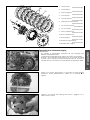
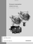
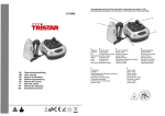
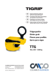
Information
Hard Equipment
Montageanleitung für Anti-Hopping-Kupplungssatz
alle Racing Modelle ab 2003
Mounting instructions for Anti-Hopping-Clutch Set
Racing Models from model 2003
Istruzioni di Montaggio Kit Frizione Anti-Hopping
tutti i mod. Racing a partire dal mod. 2003
Notice de montage embrayage Anti-Hopping
Tout modèle Racing à partir de 2003
Instrucciones de montaje para el juego de embrague Anti-Hopping
todas las Racing a partir del modelo 2003
KTM Teilenummer / Partnumber / Cod.art. / Référence / Número de la pieza KTM
59032000200
07.2005
3.211.120
DEUTSCH
Danke, daß Sie sich für KTM Hard Equipment entschlossen haben.
Alle unsere Produkte wurden nach den höchsten Standards entwickelt und gefertigt, unter Verwendung der besten verfügbaren
Materialien.
KTM Hard Equipment ist rennerprobt und gewährleistet ultimative Performance.
KTM KANN NICHT VERANTWORTLICH GEMACHT WERDEN FÜR FALSCHE MONTAGE ODER VERWENDUNG DIESES PRODUKTS. Bitte
befolgen Sie die Montageanleitung. Wenn bei der Montage Unklarheiten auftreten, wenden Sie sich bitte an eine KTM Fachwerkstätte.
ENGLISH
Thank you for choosing KTM Hard Equipment!
All of our products are designed and built to the highest standards using the finest materials available.
KTM Hard Equipment is race proven to offer the ultimate in performance.
KTM WILL NOT BE HELD LIABLE FOR IMPROPER INSTALLATION OR USE OF THIS PRODUCT. Please follow all instructions provided. If you
are unsure of any installation procedure, please contact a certified KTM dealer.
ITALIANO
Grazie per aver deciso di acquistare un prodotto KTM Hard Equipment.
Tutti i nostri prodotti sono stati sviluppati e realizzati secondo i massimi standard e con l'impiego dei migliori materiali disponibili.
Il KTM Hard Equipment è collaudato nelle competizioni ed assicura altissime prestazioni.
KTM NON PUÒ ESSERE RESA RESPONSABILE PER UN MONTAGGIO O USO IMPROPRIO DI QUESTO PRODOTTO. Per favore osservate le
istruzioni nel manuale d'uso.Se dovessero sorgere dei dubbi al montaggio, rivolgetevi ad un'officina specializzata KTM.
ESPANOL
FRANCAIS
Nous vous remercions d'avoir choisi KTM Hard Equipment.
Tous nos produits ont été développés et réalisés selon les plus hauts standards et en utilisant les meilleurs matériaux disponibles.
KTM Hard Equipment a été testé en compétition et garantit les plus hautes performances.
LA RESPONSABILITÉ DE KTM NE SAURAIT ÊTRE ENGAGÉE EN CAS D'ERREUR DANS LE MONTAGE OU L'UTILISATION DE CE PRODUIT.
Il convient de respecter les instructions de montage.
Si quelque chose n'est pas clair lors du montage, il faut s'adresser à un agent KTM.
Gracias por haberse decidido por el Hard Equipment KTM.
Todos nuestros productos han sido desarrollados y producidos según los estándares más altos utilizando los mejores materiales
disponibles.
El Hard Equipment KTM está probado en competiciones y garantiza el mejor rendimiento.
NO SE PUEDE HACER RESPONSABLE A LA KTM POR UN MONTAJE O UN USO INCORRECTO DE ESTE PRODUCTO.
Le rogamos seguir las instrucciones para el montaje.
Si durante el montaje resultan confusiones le rogamos contactar a un taller especializado KTM.
EINBAUANLEITUNG
!
EINBAUANLEITUNG
SORGFÄLTIG VOR
BEGINN
DER
ARBEIT
AM
VORSICHT
MOTOR/FAHRZEUG LESEN
!
Vorteile:
– Reduzierte Kupplungs-Betätigungskraft
– Verbesserte Dosierbarkeit der Kupplung beim Beschleunigen
– Kein Stempeln des Hinterrads beim Herunterschalten
– Verbesserte Lebensdauer von Motor und Getriebe durch Vermeidung von eingeleiteten Schlägen durch das Hinterrad
Durch das Anti-Hopping-System wird einerseits die Betätigungskraft reduziert und die Dosierung der Kupplung verbessert,
andererseits die Fahrstabilität durch Verringerung von Schlupf am Hinterrad bedingt durch die Motorbremswirkung während des
Herunterschaltens erhöht.
Das Anti-Hopping-System verwendet einen zweiteiligen Mitnehmer dessen beide Bauteile mit einer Schrägverzahnung verbunden
sind.
Bei hoher Motorbelastung (also großem Motordrehmoment) werden durch Verdrehung entsprechend der Schrägverzahnung die
beiden Bauteile des Mitnehmers gegeneinander gedrückt und damit die Kupplungsbeläge zusätzlich zu den Kupplungsfedern
aufeinander gepreßt. Durch diese zusätzliche Anpreßkraft können die Kupplungsfedern schwächer vorgespannt werden, damit tritt
beim Herunterschalten kurzzeitig Schlupf an der Kupplung auf und es wird Hinterradstempeln verhindert. Außerdem benötigen die
schwächeren Kupplungsfedern weniger Betätigungskraft, dies führt zu einer verbesserten Dosierbarkeit der Kupplung.
Anti-Hopping Einbau, Abstimmung und Wartung an KTM-Motorrädern der Serie 590
!
DER EINBAU
SOLLTE VON EINER AUTHORISIERTEN
VORSICHT
FACHWERKSTATT
!
VORGENOMMEN WERDEN
Dieser Anti-Hopping-Kupplungssatz ist speziell für KTM-Modelle der Serie 590 abgestimmt.
HINWEIS:
– Die Charakteristik kann durch die Federvorspannkraft beeinflusst werden, ist aber stark abhängig vom Verwendungszweck (SM,
SX, EXC) und dem individuellen Fahrstil des Fahrers.
– Erhöhung der Federvorspannkraft bewirkt, dass die Kupplung beim Anbremsen später öffnet (mehr Motorbremswirkung).
Zusätzlich ändert sich auch das Eingreifen der Kupplung beim Starten, jedoch sind hier die Unterschiede wesentlich geringer als
beim Anbremsen. Die Kupplung wirkt etwas agressiver.
– Grundsätzlich immer von 0 Vorspannung ausgehen und dann in 1 mm Schritten die Vorspannung erhöhen (Max 1,5 mm) bis die
optimale Einstellung für Sie persönlich gefunden wurde.
– Für den 610 CRATE-Motor und 2006 Modelle muß die Druckstange 590.32.054.000 (Länge 188 mm) verwendet werden.
Lieferumfang
– Anti-Hopping-Kupplungssatz bestehend aus folgenden Teilen:
– innere Nabe (1 Stück)
– äußere Nabe (1 Stück)
– Druckkappe (1 Stück)
– Kupplungsfedern (4 Stück)
– Öffner-Federn (4 Stück)
– Unterlagsscheiben 5,5x20x1,5 für Kupplungsfedern (4 Stück)
– Schrauben M5x25 für Kupplungsfedern (4 Stück)
– Sicherungsschrauben M4 für Anti-Hopping Einheit (4 Stück)
– Zwischenlamellen (7 Stück)
– Belaglamellen (8 Stück)
– Mitnehmerhülsen (12 Stück)
– Sicherungsblech
– Scheibe AS1226 (12x26x1)
– Druckstange (Länge 188 mm) 590.32.054.000
– Plastiksack-Inhalt:
– Scheiben für Kupplungsfedern 12,5x20x1,0 (4 Stück)
– Scheiben für Kupplungsfedern 12,5x20x2,0 (4 Stück)
– Scheiben für Kupplungsfedern 12,5x20x1,5 (4 Stück)
DEUTSCH
ANTI-HOPPING-SATZ FÜR KTM-MOTORRÄDER DER SERIE 590
3
Werkzeug
DEUTSCH
4
Für eine korrekte Montage des Anti-Hopping-Kupplungssatzes sind folgende Werkzeuge notwendig (nicht im Satz enthalten):
– 4 mm Inbusschlüssel
– 5 mm Inbusschlüssel
– 6 mm Inbusschlüssel
– 8 mm Stecknuß
– 13 mm Schlüssel
– 27 mm Stecknuß
– Drehmomentschlüssel
– Schmaler Schraubendreher
– Hammer und Flachmeißel
– Seegerringzange
– Gummiband 50 mm Durchmesser (2 Stück)
– KTM-Spezialwerkzeug 590.29.003.100
außerdem Motoröl; Spezifikation und Menge siehe KTM-Reparaturanleitung.
Vorbereitung für die Montage des Anti-Hopping-Kupplungssatzes
!
DIE
VORSICHT
SERIE 590
FOLGENDEN VORBEREITUNGEN BETREFFEN ALLE KTM-MODELLE DER
EINER AUTHORISIERTEN FACHWERKSTATT VORGENOMMEN WERDEN.
!
LAUT
ABSTIMMUNGSTABELLE. DIESE ARBEITEN
SOLLTEN VON
– Sauberen Arbeitsplatz sicherstellen.
– Wasser/Öl beständige Matte unter das Fahrzeug legen um Fahrzeugteile und Flüssigkeiten aufzunehmen.
1
– Ölablaßschraube 1 mit einem 13 mm Schlüssel öffnen und das
auslaufende Motoröl mit einem geeigneten Behälter auffangen;
entsprechend entsorgen.
– Kickstarter abmontieren (6 mm Inbus).
– Schraube M6 2 der Verbindung zwischen Fußbremshebel und
hinterem Bremszylinder entfernen.
2
DEUTSCH
– Fußbremshebel abschrauben (M8) und entfernen.
5
– alle 10 Schrauben M6 und Kupplungsdeckel 1 abnehmen.
HINWEIS:
– die Schrauben werden nach dem Einbau wieder verwendet.
– Federlasche für Bremshebelfeder nicht verlieren.
– beim Abnehmen des Kupplungsdeckel sollte die E-Starterzwischenwelle
im Motor bleiben, gegebenenfalls aus dem Kupplungsdeckel nehmen
und am Motor wieder anbringen.
1
– alle 6 Schrauben M6 der Druckkappe 2 über Kreuz lösen und
zusammen mit den Scheiben und Federn abnehmen.
2
– Druckkappe mit dem Druckpilz 3 abnehmen.
3
– Alle Belag- und Zwischenlamellen aus dem Kupplungskorb nehmen.
– Alle 12 Mitnehmerhülsen 4 entfernen
4
– Sicherungsblech 5 der Zwischenwellenmutter mit einem Flachmeißel
aufbiegen.
5
DEUTSCH
6
– Spezialwerkzeug 1 (590.29.003.100) mit 6 Mitnahmehülsen wie
gezeigt aufsetzen, an der Kurbelwelle anstehen lassen und Mutter (SW
27) lösen.
– Mutter und Sicherungsblech abnehmen, Kupplungshalter und
Mitnahmehülsen entfernen.
2
– Mitnehmer 2 von der Welle ziehen.
1
4
4
3
HINWEIS: die Stufenscheibe 3 und die beiden Halbscheiben 4 müssen
auf der Welle bleiben.
Montage Anti-Hopping-Kupplungssatz
!
VORSICHT
!
– DIE
–
FOLGENDEN ARBEITEN BETREFFEN ALLE KTM-MODELLE DER SERIE 590
LAUT
ABSTIMMUNGSTABELLE. DIESE ARBEITEN SOLLTEN VON EINER
AUTHORISIERTEN FACHWERKSTATT VORGENOMMEN WERDEN UND MÜSSEN STRIKT
BEFOLGT WERDEN.
DIE NABEN UND DIE KUPPLUNGSLAMELLEN SIND MIT 4 SICHERUNGSSCHRAUBEN
M4 VORMONTIERT, DIESE DÜRFEN VOR DER MONTAGE AM MOTOR NICHT ENTFERNT
WERDEN, WENN DOCH, MUß DER ANTI-HOPPING-KUPPLUNGSSATZ ZUSAMMENGEBAUT WERDEN WIE IM KAPITEL WARTUNG BESCHRIEBEN.
– Druckkappe vom Anti-Hopping-Kupplungssatz abnehmen.
– Anti-Hopping-Kupplungssatz am Motor montieren, wobei die
Verzahnung der Antriebswelle im inneren Anti-Hopping-Mitnehmer und
die Kupplungslamellen im Kupplungskorb eingreifen müssen.
5
HINWEIS: um den Eingriff zu erleichtern, sollte der erste Gang eingelegt
und das Hinterrad leicht vor und zurück gedreht werden; falls erforderlich
können die Sicherungsschrauben M4 der Anti-Hopping-Einheit eine halbe
Umdrehung gelöst werden, damit die Bauteile gegeneinander leicht
beweglich sind.
– Gewinde der Antriebswelle mit Loctite 243 bestreichen und ein neues
Sicherungsblech mit einer neuen Mutter montieren.
HINWEIS: das Sicherungsblech muß an der Flachstelle des Mitnehmers
eingreifen.
– Starterzwischenwelle herausziehen, das Starterzwischenrad bleibt im
Motorgehäuse.
– Kupplungskorb mit Spezialwerkzeug 590.29.003.100 5 blockieren
(siehe Photo), falls notwendig Auspuffkrümmer abbauen.
– Mutter mit 150 Nm anziehen und Sicherungsblech aufbiegen.
– Spezialwerkzeug abnehmen und Auspuffkrümmer montieren.
– Starterzwischenwelle wieder montieren.
S
1
DEUTSCH
– Sicherungsring, Scheibe und Drucklager vom Druckpilz abnehmen,
Scheibe S (AS1226 12x26x1) aufschieben; Drucklager, Scheibe und
Sicherungsring wieder am Druckpilz montieren
– Ab Modelljahr 2006 muss die Druckstange L=188 mm verbaut werden
– Druckpilz 1 und Druckkappe 2 montieren.
7
5
– Die 4 Kupplungsfedern montieren, auf die Schrauben 3 die
Unterlagscheiben 4 und je nach Verwendung (siehe Seite 1) die
erforderlichen Kupplungsfeder-Scheiben 5 (siehe Abbildung)
aufschieben.
3
2
4
5
– Schrauben eindrehen und über Kreuz auf 8 Nm anziehen.
3
6
– Die 4 Sicherungsschrauben 6 entfernen (Schrauben für spätere
Arbeiten aufheben).
!
DIE SICHERUNGSSCHRAUBEN
KUPPLUNG NICHT TRENNEN.
!
VORSICHT
MÜSSEN
ENTFERNT
WERDEN,
SONST
KANN
DIE
DEUTSCH
– Neue Kupplungsdeckeldichtung auflegen und Kupplungsdeckel
montieren, Federlasche für Bremshebelfeder nicht vergessen.
– Schrauben laut Skizze einschrauben und mit 10 Nm anziehen.
– Fußbremshebel wieder montieren (Anzugsdrehmoment 25 Nm),
Kugelgelenkschraube mit Loctite 243 sichern und mit 10 Nm
anziehen.
8
M6x30
M6x30
– Kickstarter montieren, Schraube mit Loctite 243 sichern und mit 25
Nm anziehen.
– Ölablaßschraube mit 20 Nm anziehen.
M6x35
M6x35
– Ölmeßstab am Kupplungsdeckel entfernen und 1,20 Liter Motoröl
10W/50 (z.B. Motorex Power Synt. 4T) einfüllen.
– Ölmeßstab wieder montieren und Motor auf Dichtheit prüfen.
M6x30
ZU WENIG ODER QUALITATIV
VERSCHLEIß DES MOTORS.
!
M6x30
VORSICHT
MOTORÖL
MINDERWERTIGES
!
FÜHRT ZU VORZEITIGEM
6
10
1
innere Nabe
2
äußere Nabe
3
Druckkappe
4
Kupplungsfedern
5
Öffner-Federn
590.32.002.400
11
590.32.002.450
9
590.32.003.400
590.32.005.100
7
7
13
6
6
4
7
8
8
9
12
3
10
5
11
2
12
1
13
590.32.004.200
Unterlagsscheiben Kupplungsfedern
590.32.006.100
Schrauben Kupplungsfedern
0015050253
Sicherungsschrauben
590.32.007.100
Zwischenlamellen (6x)
590.32.010.100
Zwischenlamellen (2x)
590.32.010.200
Belaglamellen
590.32.011.100
Mitnehmerhülsen
590.32.004.100
Scheiben siehe Seite 5
WARTUNG Anti-Hopping-Kupplungssatz
HINWEIS:
– Die Wartungsintervalle hängen vom Einsatzzweck ab; siehe KTMReparaturanleitung.
– Die Wartung sollte von einer authorisierten Fachwerkstatt durchgeführt
werden.
– Anti-Hopping-Kupplungssatz mit den Sicherungsschrauben blockieren
und ausbauen (siehe KTM-Reparaturanleitung), wobei zum Blockieren
des Kupplungskorbes das Spezialwerkzeug 590.29.003.100 verwendet
werden muß.
– Anti-Hopping-Kupplungssatz in einen Schraubstock einspannen
(Schonbacken verwenden!), vorsichtig die 4 Sicherungsschrauben 8
schrittweise lösen und entfernen.
8
– Anti-Hopping-Kupplungssatz aus dem Schraubstock nehmen und auf
einer sauberen Werkbank mit der äußeren Nabe nach unten ablegen.
DEUTSCH
9
9
– die äußere Nabe 1 aus der inneren Nabe 2 herausnehmen.
DEUTSCH
1
10
2
8
– Die Öffnerfedern 3 in die äußere Nabe stecken.
3
– Innere Nabe umdrehen und mit der Reibfläche nach unten ablegen, die
12 Mitnahmehülsen liegen auf der Unterlage. Beim Umdrehen müssen
die Kupplungslamellen zusammengehalten werden.
– 2 Gummibänder miteinander verknoten und das eine Gummiband
außen im Bereich zwischen der obersten Zwischenlamelle und der
Druckfläche um die innere Nabe spannen.
HINWEIS: mit dem Gummiband werden die Mitnahmehülsen in Position
gehalten.
– Alle Anti-Hopping-Teile gründlich reinigen.
!
VORSICHT
!
KEINE SCHARFEN WERKZEUGE ODER AGGRESIVE REINIGUNGSMITTEL VERWENDEN, DA
DIE REIBFLÄCHEN MIT EINEM SPEZIELLEN REIBFESTEN UND OBERFLÄCHEN
SCHÜTZENDEN BELAG BESCHICHTET SIND. AM BESTEN SOLLTEN PERCHLORETHYLENE
HÄLTIGE REINIGUNGSMITTEL VERWENDET WERDEN.
– Alle Teile mit Druckluft trocknen.
– Alle Teile auf Verschleiß prüfen und beschädigte oder verschlissene
Komponenten erneuern.
9
HINWEIS:
– die Gesamtdicke aller Belaglamellen zusammen muß zwischen 13,35
und 14,00 mm liegen.
– vor dem Zusammenbau alle Teile mit Motoröl einölen.
– die 12 Mitnahmehülsen 1 wieder montieren, wobei die Ausnehmungen
2 der Mitnahmehülsen in der inneren Nabe eingreifen müssen.
– Mitnahmehülsen mit dem Gummiband sichern.
1
1
2
4
– Mit einer Zwischenlamelle beginnend, abwechselnd alle 7 Belag- 3
und 8 Zwischenlamellen 4 montieren.
3
– Gummiband herausziehen und entfernen.
DEUTSCH
– Innere Nabe wieder umdrehen und die Kupplungslamellen abnehmen.
11
DEUTSCH
12
2
3
– Äußere Nabe 1 mit den Öffnerfedern nach oben auf die Werkbank
legen.
– Die Kupplungslamellen 2 mit den Fingern gegen die innere Nabe 3
drücken und die komplette Einheit umdrehen.
!
VORSICHT
!
AUF
DIE OBERSTE ZWISCHENLAMELLE ACHTEN, DAMIT DIESE NICHT VERSCHOBEN WIRD
UND VON DEN MITNAHMEHÜLSEN RUTSCHT.
1
– Innere Nabe mit den Kupplungslamellen entsprechend der Öffnerfedernpositionen über die äußere Nabe schieben, dabei müssen die
Schrägverzahnungen eingreifen.
– Die Kupplungslamellen sollten immer noch mit den Fingern gehalten
werden, zudem muß die äußere Nabe mit aufgenommen werden (siehe
Photo).
– Die beiden Naben gegen die Öffnerfedern zusammendrücken.
– Anti-Hopping-Kupplungssatz in einen Schraubstock einspannen,
Schraubstock leicht zusammenziehen, es muß nur sichergestellt sein,
daß die oberste Zwischenlammele nicht verrutschen kann.
– Mit einem schmalen Schraubendreher die Öffnerfedern in deren Sitze
positionieren.
– Alle 4 Anti-Hopping-Sicherungsschrauben (M4) einschrauben.
HINWEIS: die Schrauben nur so weit eindrehen, daß die
Kupplungslamellen noch gegeneinander verdreht werden können, da diese
bei der Montage im Kupplungskorb ausgerichtet werden müssen.
– Kupplungssatz aus dem Schraubstock nehmen.
– nach der Montage im Kupplungskorb die Schrauben anziehen und erst
nachdem die Druckkappe montiert wurde wieder entfernen (siehe AntiHopping-Montage).
!
VORSICHT
WERDEN DIE ANTI-HOPPING-SICHERUNGSSCHRAUBEN NICHT
KUPPLUNG NICHT UND DAS MOTORRAD FÄHRT BEIM STARTEN
!
ENTFERNT, TRENNT DIE
AN.
10
–
–
–
–
–
–
–
11
–
–
–
–
–
–
–
–
–
–
Arbeiten nur an einem sauberen Arbeitsplatz durchführen.
Wird der Motor in geschlossenen Räumen gestartet, immer für entsprechende Belüftung und Abgasabsaugung sorgen.
Motorrad nur auf einem ebenen festen Untergrund mit einer geeigneten Vorrichtung anheben, im angehobenen Zustand sichern.
Arbeitskleidung und Werkstatt bzw. Werkstattausrüstung muß den gesetzlichen Vorschriften entsprechen.
Nichtauthorisierte Personen und Kinder aus dem Arbeitsbereich fernhalten.
Vor Arbeitsbeginn Motor abstellen und auskühlen lassen um Verbrennungen an heißen Teilen zu verhindern.
Vorsicht bei heißen Flächen und offenen Flammen, die meisten Flüssigkeiten wie Kraftstoff sind leicht brennbar bzw. entwickeln
giftige Dämpfe.
Ausgelaufenen Flüssigkeiten müssen entsprechend entsorgt werden.
Die nicht bestimmungsgerechte Verwendung von Anti-Hopping-Teilen ist nicht zulässig.
Vor der Montage prüfen, ob der Anti-Hopping-Kupplungssatz vollständig und beschädigungsfrei ist.
Fahrzeugzustand vor der Montage des Anti-Hopping-Kupplungssatz überprüfen.
Es wird speziell darauf hingewiesen, daß alle Sicherheitsvorschriften zu beachten sind, für aus fehlerhafter Montage
resultierende Schäden und Verletzungen wird nicht gehaftet. Bei unsachgemäßer Verwendung, falscher Montage und
Modifikationen wird keine Garantie übernommen.
Die beschriebene Funktion gilt nur für Fahrzeuge in Originalzustand, die keine Mängel oder Veränderungen aufweisen.
KTM behält sich das Recht vor, Änderungen am Produkt wie auch an der Dokumentation nach eigener Entscheidung
vorzunehmen.
Der Anti-Hopping-Kupplungssatz beinhaltet eine Mehrscheibenkupplung als Fahrzeugbestandteil, für den möglicherweise eine
Homologation nach den jeweiligen lokalen Gesetzen notwendig ist.
Der Anti-Hopping-Kupplungssatz wurde durch den Fahrzeughersteller geprüft.
Nach der Montage des Anti-Hopping-Kupplungssatzes ist möglicherweise eine Neu-Homologation des Fahrzeugs notwendig.
DEUTSCH
Allgemeine Hinweise:
13
ANTI-HOPPING SET FOR KTM 590 SERIES MOTORCYCLES
MOUNTING INSTRUCTIONS
!
READ
CAUTION
!
THE MOUNTING INSTRUCTIONS BEFORE STARTING TO WORK ON THE ENGINE/VEHICLE.
Advantages:
– Less force required to actuate the clutch
– Improved controllability of the clutch when accelerating
– No rear wheel hopping when shifting down
– Prolonged service life of the engine and transmission by avoiding applied impact from the rear wheel
The Anti-Hopping system reduces the clutch actuating force and improves the controllability of the clutch while increasing the
driving stability by reducing rear wheel hopping when shifting down by means of the engine braking effect.
ENGLISH
The Anti-Hopping system uses a two-piece driver whose components are connected by helical gears.
At a high engine load (i.e. high engine torque) the two driver components are pressed against each other by turning in accordance
with the helical gears, causing the clutch linings as well as the clutch springs to be pressed together. This additional pressure force
makes it possible to reduce the clutch spring preload, slip on the clutch briefly occurs when shifting down and prevents rear wheel
hopping. The weaker clutch springs also require less actuating power, resulting in an improved controllability of the clutch.
Installing the Anti-Hopping, tuning and service for KTM 590 series motorcycles
!
THE ANTI-HOPPING
CAUTION
!
SYSTEM SHOULD BE INSTALLED BY AN AUTHORIZED WORKSHOP.
The Anti-Hopping clutch set is specially designed for KTM models in the 590 series.
14
NOTE:
– The characteristics can be influenced by the spring preload but are highly dependent on the intended purpose (SM, SX, EXC)
and the driver's personal style of driving.
– Increasing the spring preload delays the opening of the clutch when braking (higher engine braking effect). The clutch also
engages differently when starting but this difference is not as notable as the difference when braking. The clutch feels slightly
more aggressive.
– Generally always proceed from 0 mm preload and increase the preload in 1 mm increments (max. 1.5 mm) until you find the
setting that's right for you.
– The pushrod 590.32.054.000 (length 188 mm) must be used for the 610 CRATE engine and all 2006 models.
Scope of supply
– Anti-Hopping clutch set comprising:
– Inner hub (1 piece)
– Outer hub (1 piece)
– Pressure cap (1 piece)
– Clutch springs (4 pieces)
– Opener springs (4 pieces)
– 5.5x20x1.5 washer for clutch springs (4 pieces)
– M5x25 screw for clutch springs (4 pieces)
– M4 lock screw for Anti-Hopping unit (4 pieces)
– Clutch disk (7 pieces)
– Lining disks (8 pieces)
– Driving sleeve (12 pieces)
– Lock washer
– Washer AS1226 (12x26x1)
– pushrod (length 188 mm) - 590.32.054.000
– Plastic bag containing:
– Washers for clutch springs 12.5x20x1.0 (4 pieces)
– Washers for clutch springs 12.5x20x2.0 (4 pieces)
– Washers for clutch springs 12.5x20x1.5 (4 pieces)
1
Tools
The following tools will also be required to mount the Anti-Hopping clutch set (not included in the scope of supply):
– 4 mm hexagon socket wrench
– 5 mm hexagon socket wrench
– 6 mm hexagon socket wrench
– 8 mm wrench socket
– 13 mm wrench
– 27 mm wrench socket
– Torque wrench
– Narrow screwdriver
– Hammer and flat chisel
– Circlip pliers
– 50 mm diameter rubber band (2 pieces)
– KTM special tool 590.29.003.100
Preparing to mount the Anti-Hopping clutch set
!
THE
FOLLOWING PREPARATIONS APPLY TO ALL
BY AN AUTHORIZED WORKSHOP.
KTM
MODELS IN THE
CAUTION
590 SERIES SHOWN
!
IN THE TUNING CHART.
THIS
WORK SHOULD BE PERFORMED
– Make sure the workplace is clean.
– Spread a mat resistant to water/oil under the vehicle to absorb fluids and hold vehicle parts.
ENGLISH
as well as engine oil; for specification and quantity, see KTM Repair Manual.
15
2
– Open the oil drain plug 1 with a 13 mm wrench and drain the engine
oil into a suitable vessel; properly dispose of the engine oil.
1
– Dismount the kickstarter (6 mm hexagon wrench).
– Remove the M6 screw 2 on the connection between the foot brake
lever and the rear brake cylinder.
2
– Unscrew the foot brake lever (M8) and remove.
– Remove all 10 M6 screws and the clutch cover 1.
ENGLISH
NOTE:
– the screws will be used again.
– Do not lose the spring hanger for the brake lever spring.
– When removing the clutch cover make sure the electric starter idler
shaft stays in the engine, if necessary, remove from the clutch cover
and attach to the engine.
1
16
– Loosen all 6 M6 screws on the pressure cap 2 crosswise and remove
together with the washers and springs.
2
3
– Remove the pressure cap with the pressure piece 3.
– Take all of the lining and clutch disks out of the outer clutch hub.
– Remove all 12 driving sleeves 4.
4
– Bend up the lock washer 5 on the idler shaft nut with a flat chisel.
5
– Apply the special tool 1 (590.29.003.100) with 6 driving sleeves as
illustrated, hold against the crankshaft and loosen the nut (A/F 27).
– Remove the nut and lock washer, the clutch holder and the driving
sleeves.
– Pull the driver 2 off the shaft.
2
1
NOTE: leave the stepped disk 3 and the two half disks 4 on the shaft.
3
ENGLISH
4
17
Mounting the Anti-Hopping clutch set
!
– THE
–
CAUTION
TO ALL KTM MODELS
!
FOLLOWING WORK APPLIES
IN THE 590 SERIES SHOWN
IN THE TUNING CHART. THIS WORK SHOULD BE PERFORMED BY AN AUTHORIZED
WORKSHOP, STRICTLY FOLLOWING THE INSTRUCTIONS.
THE HUBS AND THE CLUTCH DISKS ARE PRE-MOUNTED WITH 4 M4 LOCK SCREWS.
DO NOT REMOVE FROM THE ENGINE PRIOR TO MOUNTING. IF THEY ARE REMOVED,
THE ANTI-HOPPING CLUTCH SET MUST BE ASSEMBLED AS DESCRIBED IN THE
"MAINTENANCE" CHAPTER.
– Remove the pressure cap from the Anti-Hopping clutch set.
– Mount the Anti-Hopping clutch set on the engine. Make sure the
toothing on the main shaft engages in the inner Anti-Hopping driver
and the clutch disks engage in the outer clutch hub.
5
NOTE: it will be easier to mount if you engage first gear and turn the rear
wheel back and forth; if necessary, loosen the M4 lock screws on the
Anti-Hopping unit half a turn to make the components movable.
– Apply Loctite 243 to the thread on the main shaft and mount a new
lock washer with a new nut.
NOTE: the lock washer must engage in the flat part of the driver.
– Pull out the starter idler shaft, leaving the starter idler gear in the
engine case.
– Block the outer clutch hub with special tool 590.29.003.100 5 (see
photo). If necessary, dismount the exhaust manifold.
– Tighten the nut to 150 Nm and bend up the lock washer.
– Remove the special tool and mount the exhaust manifold.
– Remount the starter idler shaft.
– Remove the retaining ring, washer and thrust bearing from the
pressure piece, mount the washer S (AS1226 12x26x1); remount the
thrust bearing, washer and retaining ring on the pressure piece
– The pushrod (length 188 mm) must be installed starting with model
year 2006.
– Mount the pressure piece 1 and the pressure cap 2.
S
1
ENGLISH
– Mount the 4 clutch springs, place the washers 4 on the screws 3 and
(depending on the intended purpose - see page 1) add the required
clutch spring disks 5 (see illustration).
3
2
4
18
5
– Turn in the screws and tighten crosswise to 8 Nm.
3
6
– Remove the 4 lock screws 6 (save screws for later).
!
REMOVE
CAUTION
!
THE LOCK SCREWS OTHERWISE THE CLUTCH WILL NOT DISENGAGE.
– Put a new clutch cover gasket in place and mount the clutch cover (do
not forget the spring hangar for the brake lever spring).
– Mount the screws as illustrated and tighten to 10 Nm.
– Mount the foot brake lever (torque: 25 Nm), apply Loctite 243 to the
ball-joint screw and tighten to 10 Nm.
M6x30
M6x35
M6x35
– Tighten the oil drain plug to 20 Nm.
– Remove the oil dipstick from the clutch cover and add 1.20 liters of
10W/50 engine oil (e.g. Motorex Power Synt. 4T).
– Mount the oil dipstick and check the engine for leaks.
!
M6x30
M6x30
NOT
CAUTION
!
ENOUGH ENGINE OIL OR LOW-GRADE ENGINE OIL WILL CAUSE PREMATURE
ENGINE WEAR.
ENGLISH
M6x30
– Mount the kickstarter, apply Loctite 243 to the screw and tighten to
25 Nm.
19
9
10
1
Inner hub
2
Outer hub
3
Pressure cap
4
Clutch springs
5
Opener springs
590.32.002.400
11
590.32.002.450
9
590.32.003.400
590.32.005.100
7
13
6
6
4
7
8
8
ENGLISH
9
12
3
10
5
11
2
12
1
13
590.32.004.200
Washers for clutch springs
590.32.006.100
Screws for clutch springs
0015050253
Lock screws
590.32.007.100
Clutch disks (6x)
590.32.010.100
Clutch disks (2x)
590.32.010.200
Lining disks
590.32.011.100
Driving sleeves
590.32.004.100
Washers see page 5
20
Servicing the Anti-Hopping clutch set
NOTE:
– Service intervals depend on the intended purpose; see KTM Repair
Manual.
– Have the service performed by an authorized workshop.
– Block the Anti-Hopping clutch set with the lock screws and dismount
(see KTM Repair Manual). Use the special tool 590.29.003.100 to
block the outer clutch hub.
– Clamp the Anti-Hopping clutch set in a vise (use protective jaws),
carefully loosen the 4 lock screws 8 and remove.
8
– Take the Anti-Hopping clutch set out of the vise and place on a clean
workbench with the outer hub facing down.
– Remove the outer hub 1 from the inner hub 2.
1
2
– Insert the opener springs 3 in the outer hub.
ENGLISH
3
21
– Turn the inner hub over and lay it on its friction surface; the 12 driving
sleeves will lie face down on the mat. Hold the clutch disks in place
while turning the hub over.
– Tie the 2 rubber bands together and stretch one rubber band around
the outside of the inner hub between the upper clutch disk and the
pressure area.
NOTE: the rubber band will hold the driving sleeves in place.
– Turn the inner hub over again and remove the clutch disks.
– Thoroughly clean all Anti-Hopping components.
!
!
CAUTION
DO
NOT USE SHARP TOOLS OR AGGRESSIVE DETERGENTS SINCE THE FRICTION
SURFACES HAVE A SPECIAL ABRASION RESISTANT AND PROTECTIVE COATING. WE
RECOMMEND USING CLEANSERS CONTAINING PERCHLOROETHYLENE.
– Dry all components with compressed air.
– Check all components for wear; replace any damaged or worn
components.
NOTE:
– All lining disks together should have a total thickness between 13.35
and 14.00 mm.
– Oil all components with engine oil before assembling.
ENGLISH
– Mount the 12 driving sleeves 1 again; make sure the recesses 2 in the
driving sleeves engage in the inner hub.
– Hold the driving sleeves in place with the rubber band.
1
1
22
2
4
3
– Start with one clutch disk and alternately mount all 7 lining disks 3
and 8 clutch disks 4.
– Remove the rubber band.
9
2
3
– Place the outer hub 1 on the workbench with the opener springs
facing up.
– Press the clutch disks 2 against the inner hub 3 with your fingers
and turn the entire unit over.
!
CAUTION
!
MAKE
SURE THE UPPER CLUTCH DISK DOES NOT MOVE AND SLIDE OFF THE DRIVING
SLEEVE.
1
– Slide the inner hub with the clutch disks over the outer hub
corresponding to the opener spring positions, making sure the helical
gears engage.
– Always hold the clutch disks with your fingers, also holding on to the
outer hub (see photo).
– Clamp the Anti-Hopping clutch set in a vise, carefully tighten the vise,
making sure the upper clutch disk cannot move.
– Position the opener springs in their seats with a narrow screwdriver.
ENGLISH
– Press the two hubs against the opener springs.
23
10
– Mount all 4 Anti-Hopping lock screws (M4).
NOTE: turn in the screws but make sure the clutch disks can still be
moved. They will need to be aligned when they are mounted in the outer
clutch hub.
– Remove the clutch set from the vise.
– After mounting the Anti-Hopping clutch set in the outer clutch hub,
tighten the screws and do not remove until the pressure cap is
mounted (see Mounting the Anti-Hopping).
!
IF
CAUTION
!
THE ANTI-HOPPING LOCK SCREWS ARE NOT REMOVED, THE CLUTCH WILL NOT
DISENGAGE AND THE MOTORCYCLE WILL DRIVE OFF WHEN STARTED.
General information
–
–
–
–
–
–
–
–
–
–
–
–
ENGLISH
24
–
–
–
–
–
Only work at a clean workplace.
If starting the engine in an enclosed room, provide for adequate ventilation and emissions extraction.
Always jack up the motorcycle with a suitable device on a firm and level surface and secure when raised.
The working clothes, the workshop and the workshop equipment must comply with the legal regulations.
Keep unauthorized persons and children away from the work area.
Switch off the engine and allow to cool down before starting to work to avoid being burned by hot components.
Keep hot surfaces away from open fire; many liquids such as fuel are highly combustible and can develop toxic vapors.
Properly dispose of any drained fluids.
The use of the Anti-Hopping components for purposes other than the intended purpose is prohibited.
Check whether the Anti-Hopping clutch set is complete and undamaged prior to mounting.
Check the vehicle condition before mounting the Anti-Hopping clutch set.
We specifically emphasize that all safety regulations must be observed; no liability will be assumed for damage or injuries
arising from improper mounting. The warranty will become null and void in cases of improper use, incorrect mounting or any
modifications.
The described function only applies to vehicles in their original condition without any defects or modifications.
KTM reserves the right to modify the product or the documentation.
Anti-Hopping clutch set is a multidisk clutch and vehicle component for which a type approval may be required under the local
law.
The Anti-Hopping clutch set was tested by the vehicle manufacturer.
Rehomologation of the vehicle may be required after the Anti-Hopping clutch set is mounted.
11
KIT ANTI-HOPPING PER MOTOCICLETTE KTM SERIE 590
ISTRUZIONI DI MONTAGGIO
!
LEGGERE
AVVERTIMENTO
!
ATTENTAMENTE LE ISTRUZIONI DI MONTAGGIO PRIMA DI PROCEDERE AI LAVORI SUL MOTORE/VEICOLO!
Vantaggi:
– ridotto sforzo alla leva frizione
– miglior modulabilità della frizione all'accelerazione
– niente saltellamento della ruota posteriore alla scalata delle marce
– più lunga durata del motore e del cambio grazie ai ridotti colpi della ruota posteriore
Il sistema Anti-Hopping riduce da un lato lo sforzo da applicare alla leva e migliora la modulabilità della frizione, dall'altro aumenta
la stabilità di guida riducendo lo slittamento della ruota posteriore dovuto all'effetto frenante del motore durante la scalata delle
marce.
Il sistema Anti-Hopping impiega un mozzo costituito da due parti collegate tra loro attraverso una dentatura obliqua. Ad alto carico
del motore (e quindi ad alta coppia) i due componenti del mozzo, girandosi in corrispondenza della dentatura obliqua, vengono
pressati l'uno contro l'altro comprimendo oltre alle molle frizione anche i dischi guarniti. Attraverso questa addizionale forza di
pressione è sufficiente meno precarico delle molle frizione, così alla scalata delle marce si verifica un breve slittamento della
frizione che previene il saltellamento della ruota posteriore. Le molle frizione più morbide richiedono inoltre meno sforzo alla leva
dal che consegue anche una miglior modulabilità della frizione.
Montaggio, taratura e manutenzione Anti-Hopping su motociclette KTM serie 590
!
IL
AVVERTIMENTO
KTM.
!
MONTAGGIO DOVREBBE ESSERE ESEGUITO DA UN'OFFICINA AUTORIZZATA
AVVERTENZA:
– La caratteristica può essere influenzata dalla forza di precarico delle molle, ma dipende soprattutto dall'impiego (SM, SX, EXC)
e dallo stile di guida individuale del pilota.
– Un aumento della forza di precarico determina che in staccata la frizione apre più tardi (maggior effetto frenante del motore).
Inoltre varia anche l'innesto della frizione all'avviamento, in questo caso le differenze però sono molto meno significative che in
staccata. La frizione sembra più aggressiva.
– Per principio partire sempre dal precarico 0 e poi aumentare il precarico a passi di rispettivamente 1 mm (max. 1,5 mm) fino ad
ottenere la regolazione che pare ottimale.
– Per il motore da corsa 610cc e nei modelli 2006 è necessario usare l'asta di spinta 590.32.054.000 (lunghezza 188 mm).
Volume della fornitura
1
– Kit frizione Anti-Hopping composto dai seguenti componenti:
– mozzo interno (1 pezzo)
– mozzo esterno (1 pezzo)
– piatto spingidisco (1 pezzo)
– molle frizione (4 pezzi)
– molle di apertura (4 pezzi)
– rasamenti 5,5x20x1,5 per molle frizione (4 pezzi)
– viti M5x25 per molle frizione (4 pezzi)
– viti di sicurezza M4 per gruppo Anti-Hopping (4 pezzi)
– dischi intermedi (7 pezzi)
– dischi guarniti (8 pezzi)
– bussole di trascinamento (12 pezzi)
– piastrina di sicurezza
– rondella AS1226 (12x26x1)
– l'asta di spinta L=188 - 590.32.054.000
– Contenuto sacchetto:
– rondelle per molle frizione 12,5x20x1,0 (4 pezzi)
– rondelle per molle frizione 12,5x20x2,0 (4 pezzi)
– rondelle per molle frizione 12,5x20x1,5 (4 pezzi)
ITALIANO
Il presente kit frizione Anti-Hopping è specificamente tarato per modelli KTM serie 590.
25
Attrezzi
Per il corretto montaggio del kit frizione Anti-Hopping sono necessari i seguenti attrezzi (non contenuti nel kit):
– chiave a brugola 4 mm
– chiave a brugola 5 mm
– chiave a brugola 6 mm
– bussola 8 mm
– bussola 13 mm
– bussola 27 mm
– chiave dinamometrica
– cacciavitino
– martello e scalpello piatto
– pinza per anelli Seeger
– elastico diam. 50 mm (2 pezzi)
– attrezzo speciale KTM 590.29.003.100
inoltre dell'olio motore; per specifiche e quantità vedi nel manuale di riparazione KTM.
Preparazione montaggio kit frizione Anti-Hopping
!
I
SEGUENTI PREPARATIVI RIGUARDANO TUTTI I MODELLI
ESEGUITI DA UN'OFFICINA AUTORIZZATA KTM.
KTM
AVVERTIMENTO
590 COME DA
DELLA SERIE
!
TABELLA DI TARATURA.
QUESTI
LAVORI DOVREBBERO ESSERE
– Provvedere ad un posto di lavoro pulito.
– Stendere una stuoia resistente all'acqua/olio sotto il veicolo per raccogliere i pezzi ed i liquidi della moto.
ITALIANO
1
– Aprire la vite di scarico olio 1 con una chiave da 13 mm e raccogliere
l'olio motore defluente in un recipiente adatto; provvedere al regolare
smaltimento.
2
26
– Smontare il pedale avviamento (chiave a brugola 6 mm).
– Togliere la vite M6 2 dal collegamento tra pedale freno e pompa freno
posteriore.
2
– Svitare (M8) e togliere il pedale freno.
– Togliere tutte le 10 viti M6 ed il coperchio frizione 1.
AVVERTENZA:
– Dopo il montaggio le viti vengono riutilizzate.
– Non perdere la piastrina di attacco per la molla del pedale freno.
– Alla rimozione del coperchio frizione l'albero intermedio
dell'avviamento elettrico dovrebbe rimanere nel motore, altrimenti
toglierlo dal coperchio frizione e rimontarlo nel motore.
– Svitare con sequenza a croce tutte le 6 viti M6 del piatto spingidisco
2 e toglierle unitamente alle rondelle e le molle.
2
ITALIANO
1
27
3
– Togliere il piatto spingidisco ed il cuscinetto reggispinta 3.
3
– Togliere il pacco dischi dalla campana frizione.
– Togliere le 12 bussole di trascinamento 4.
4
– Con lo scalpello piatto ripiegare la piastrina di sicurezza 5 del dado
dell'albero intermedio.
5
– Posizionare come illustrato l'attrezzo speciale 1 (590.29.003.100)
con 6 bussole di trascinamento, portarlo a battuta contro l'albero
motore e svitare il dado (bussola 27 mm).
– Togliere il dado e la piastrina di sicurezza, rimuovere il fermo frizione e
le bussole di trascinamento.
2
– Sfilare il mozzo frizione 2 dall'albero.
1
4
3
AVVERTENZA: La rondella a gradino 3 e le due semirondelle 4 devono
rimanere sull'albero.
Montaggio kit frizione Anti-Hopping
AVVERTIMENTO
!
– I SEGUENTI LAVORI RIGUARDANO TUTTI I MODELLI KTM DELLA SERIE 590 COME
DA TABELLA DI TARATURA. QUESTI LAVORI DOVREBBERO ESSERE ESEGUITI DA
UN'OFFICINA AUTORIZZATA KTM RISPETTANDO RIGOROSAMENTE LE PRESENTI
ISTRUZIONI.
– I MOZZI ED I DISCHI FRIZIONE SONO PREMONTATI CON 4 VITI DI SICUREZZA M4
CHE NON DEVONO ESSERE TOLTE PRIMA DEL MONTAGGIO NEL MOTORE. NEL CASO
SIANO STATE TOLTE, IL KIT FRIZIONE ANTI-HOPPING DEVE ESSERE ASSEMBLATO
COME DESCRITTO NEL CAPITOLO MANUTENZIONE.
ITALIANO
!
– Togliere il piatto spingidisco dal kit frizione Anti-Hopping.
– Montare il kit frizione Anti-Hopping sul motore facendo attenzione che
la dentatura dell'albero motore ingrani con il mozzo esterno dell'AntiHopping ed i dischi frizione con la campana frizione.
28
5
AVVERTENZA: Per facilitare l'operazione è opportuno innestare la prima
marcia e girare la ruota posteriore leggermente in avanti ed indietro; se
necessario, le viti di sicurezza M4 del gruppo Anti-Hopping possono
essere allentate di mezzo giro per permettere un facile movimento tra i
componenti.
– Spalmare il filetto dell'albero primario con Loctite 243 ed infilarvi una
nuova piastrina di sicurezza ed un nuovo dado.
– Estrarre l'albero intermedio d'avviamento, l'ingranaggio intermedio
d'avviamento rimane nel carter motore.
AVVERTENZA: La piastrina di sicurezza deve ingranare nel punto piano
del mozzo.
– Bloccare la campana frizione con l'attrezzo speciale 590.29.003.100
5 (vedi foto), all'occorrenza smontare il collettore di scarico.
– Serrare il dado a 150 Nm e piegare in alto la piastrina di sicurezza.
– Togliere l'attrezzo speciale e rimontare il collettore di scarico.
– Rimontare l'albero intermedio d'avviamento.
– Togliere l'anello di sicurezza, la rondella ed il cuscinetto dal fungo
reggispinta, infilarvi la rondella S (AS1226 12x26x1); rimontare il
cuscinetto, la rondella e l'anello di sicurezza sul fungo reggispinta.
– A partire dai modelli 2006 deve essere montata l'asta di spinta L=188.
– Montare il cuscinetto reggispinta 1 ed il piatto spingidisco 2.
S
1
– Montare le 4 molle frizione ed infilare sulle viti 3 i rasamenti 4 ed, a
seconda del modello (vedi a pagina 1), le rondelle richieste 5 (vedi
figura).
3
2
4
ITALIANO
5
– Montare le viti e serrarle con sequenza a croce a 8 Nm.
3
29
6
– Togliere le quattro viti di sicurezza 6 (conservarle per futuri
interventi).
!
LE
AVVERTIMENTO
!
VITI DI SICUREZZA DEVONO ESSERE TOLTE, ALTRIMENTI LA FRIZIONE NON PUÒ
STACCARE.
– Applicare una nuova guarnizione coperchio frizione e montare il
coperchio, non dimenticare la piastrina di attacco per la molla pedale
freno.
– Avvitare le viti come da schizzo e serrarle a 10 Nm.
– Rimontare il pedale freno (coppia di serraggio 25 Nm), assicurare la
vite della testa a snodo con Loctite 243 e serrarla a 10 Nm.
– Rimontare il pedale avviamento, assicurare la vite con Loctite 243 e
serrarla a 25 Nm.
– Serrare la vite di scarico olio a 20 Nm.
M6x30
M6x30
M6x35
M6x35
M6x30
ITALIANO
30
M6x30
– Togliere l'astina livello olio dal coperchio frizione ed introdurre 1,20
litri di olio motore (p.es. Motorex Power Synt. 4T).
– Rimontare l'astina livello olio e controllare la tenuta del motore.
!
AVVERTIMENTO
UNA QUANTITÀ TROPPO ESIGUA DI OLIO O OLIO DI
UN'USURA PRECOCE DEL MOTORE.
!
SCARSA QUALITÀ PROVOCA
9
10
1
mozzo interno
2
mozzo esterno
3
piatto spingidisco
4
molle frizione
5
molle di apertura
590.32.002.400
11
590.32.002.450
9
590.32.003.400
590.32.005.100
7
13
6
6
4
7
8
8
9
12
3
10
5
11
2
12
1
13
590.32.004.200
rasamenti per molle frizione
590.32.006.100
viti per molle frizione
0015050253
viti di sicurezza
590.32.007.100
dischi intermedi (6x)
590.32.010.100
dischi intermedi (2x)
590.32.010.200
dischi guarniti
590.32.011.100
bussole di trascinamento
590.32.004.100
Rondelle vedi a pag. 5
AVVERTENZA:
– Gli intervalli di manutenzione dipendono dal tipo d'impiego; vedi
Manuale di Riparazione KTM.
– La manutenzione dovrebbe essere eseguita da un'officina autorizzata.
– Bloccare il kit frizione Anti-Hopping con le viti di sicurezza utilizzando
a questo scopo l'attrezzo speciale 590.29.003.100 per bloccare la
campana frizione, e smontare il kit (vedi Manuale di Riparazione KTM).
ITALIANO
Manutenzione kit frizione Anti-Hopping
31
– Serrare il kit frizione Anti-Hopping in una morsa (utilizzare ganasce
protettive!), svitare gradualmente le quattro viti di sicurezza 8 e
toglierle.
8
– Togliere il kit frizione Anti-Hopping dalla morsa e poggiarlo con il
mozzo interno in basso.
– Togliere il mozzo esterno 1 da quello interno 2.
1
2
– Inserire le molle di apertura 3 nel mozzo esterno.
3
ITALIANO
– Girare il mozzo interno e poggiarlo con la superficie di attrito in basso,
le 12 bussole di trascinamento poggiano sulla base di appoggio.
Quando si rivolta il mozzo, i dischi frizione devono essere tenuti
insieme con le mani.
32
– Annodare due elastici e serrarne uno tra il disco intermedio superiore e
la superficie di spinta intorno al mozzo interno.
AVVERTENZA: L'elastico tiene in posizione le bussole di trascinamento.
– Rivoltare nuovamente il mozzo interno e togliere i dischi frizione.
– Pulire accuratamente tutti i componenti Anti-Hopping.
!
AVVERTIMENTO
!
NON USARE ATTREZZI ACUMINATI O DETERGENTI AGGRESSIVI, PERCHÉ LE SUPERFICI
D'ATTRITO SONO RICOPERTE DI UNO SPECIALE RIVESTIMENTO PROTETTIVO RESISTENTE
ALL'ATTRITO. È PREFERIBILE L'USO DI DETERGENTI CONTENENTI PERCLOROETILENE.
– Asciugare tutti i componenti con aria compressa.
– Verificare l'usura di tutti i componenti e sostituire quelli danneggiati o
usurati.
AVVERTENZA:
– Lo spessore totale dei dischi guarniti messi insieme deve essere tra
13,35 e 14,00 mm.
– Prima dell'assemblaggio oliare tutti i componenti con olio motore.
– Rimontare le 12 bussole di trascinamento 1 facendo attenzione che le
aperture 2 delle bussole ingranino con il mozzo interno.
– Assicurare le bussole di trascinamento con l'elastico.
1
2
4
3
– Cominciando con un disco intermedio, inserire alternativamente i 7
dischi guarniti 3 e gli 8 dischi intermedi 4.
ITALIANO
1
33
– Togliere l'elastico.
2
3
– Poggiare il mozzo esterno 1 con le molle di apertura in alto sul banco
di lavoro.
– Premere il pacco dischi 2 con le dita contro il mozzo interno 3 e
rivoltare l'unità completa.
!
!
AVVERTIMENTO
FAR
ATTENZIONE CHE IL DISCO INTERMEDIO SUPERIORE NON VENGA SPOSTATO E NON
SCIVOLI DALLE BUSSOLE DI TRASCINAMENTO.
1
– Spingere il mozzo interno con i dischi frizione in corrispondenza delle
posizioni delle molle di apertura sul mozzo esterno facendo attenzione
che ingranino le dentature oblique.
– Tenendo tuttora insieme i dischi frizione con le dita, afferrare ora
anche il mozzo esterno (vedi foto).
– Comprimere i due mozzi contro la forza delle molle di apertura.
– Serrare il kit frizione Anti-Hopping in una morsa e stringere
leggermente la morsa per assicurare che il disco intermedio superiore
non si sposti.
– Con un cacciavitino posizionare le molle di apertura nelle loro sedi.
– Avvitare tutte le 4 viti di sicurezza Anti-Hopping (M4).
ITALIANO
AVVERTENZA: Avvitare le viti solo quanto basta per poter ancora girare
tra di loro i dischi frizione i quali vanno ancora allineati al montaggio
nella campana frizione.
– Togliere il kit frizione dalla morsa.
– Dopo il montaggio nella campana frizione serrare le viti e toglierle solo
dopo aver serrato correttamente il piatto spingidisco (vedi cap.
Montaggio kit frizione Anti-Hopping).
!
34
AVVERTIMENTO
SE LE VITI DI SICUREZZA ANTI-HOPPING NON VENGONO
STACCA E LA MOTO PARTE ALL'AVVIAMENTO.
!
TOLTE, LA FRIZIONE NON
Avvertenze generali:
–
–
–
–
–
–
–
–
–
–
Eseguire i lavori solo ad un posto di lavoro pulito.
Se si avvia il motore in locali chiusi, provvedere sempre ad una sufficiente aerazione ed aspirazione dei gas di scarico.
Alzare la moto solo su un fondo piano e solido mediante un dispositivo adatto ed assicurarla nella posizione alzata.
Gli indumenti di lavoro e l'officina ossia l'attrezzatura dell'officina devono essere conformi alle relative disposizioni di legge.
Tener fuori dalla zona di lavoro le persone non autorizzate ed i bambini.
Prima di iniziare il lavoro spegnere il motore e farlo raffreddare per evitare scottature a parti calde.
Attenzione con superfici calde e fiamme aperte, la maggior parte dei liquidi come il carburante sono facilmente infiammabili o
sviluppano vapori tossici.
I liquidi fuoriusciti devono essere raccolti e smaltiti regolarmente.
Non è consentito un uso di componenti Anti-Hopping diverso da quello previsto.
Prima del montaggio verificare che il kit frizione Anti-Hopping sia completo e privo di danneggiamenti.
Verificare le condizioni del veicolo prima di montare il kit frizione Anti-Hopping.
Si raccomanda espressamente di osservare tutte le disposizioni di sicurezza. Non si risponde per danni o lesioni dovuti ad un
montaggio non corretto. Non ci si assume alcuna garanzia in caso di uso improprio, montaggio non corretto o modifiche
apportate alla frizione Anti-Hopping.
La funzione descritta vale solo per veicoli allo stato originale che non presentino difetti o modifiche.
KTM si riserva il diritto di apportare a propria discrezione modifiche al prodotto ed alla documentazione.
Il kit frizione Anti-Hopping è una frizione multidisco e quindi un componente del veicolo per il quale è eventualmente
necessaria un'omologazione secondo le normative locali.
La frizione Anti-Hopping è stata testata ed approvata dal costruttore dei veicoli.
Dopo il montaggio il kit frizione Anti-Hopping potrebbe essere richiesta una nuova omologazione del veicolo.
ITALIANO
–
–
–
–
–
–
–
35
KIT ANTI-HOPPING POUR MOTOS KTM DE LA SÉRIE 590
NOTICE DE MONTAGE
!
LIRE
ATTENTION
!
ATTENTIVEMENT LA NOTICE AVANT DE PROCÉDER AU MONTAGE SUR LE MOTEUR OU LA MOTO
Les avantages en sont :
– Moins de dureté à la commande
– Un meilleur dosage de l'embrayage à l'accélération
– Pas de sautillement de la roue au rétrogradage
– Longévité accrue du moteur et de la boîte de vitesses par suppression des à-coups engendrés par la roue arrière
Le système Anti-Hopping d'une part réduit la dureté à la commande et facilite le dosage de l'embrayage, d'autre part il améliore la
tenue de route en réduisant le décrochage de la roue arrière engendré par le frein moteur au rétrogradage.
Le système Anti-Hopping utilise une noix en deux parties dont les deux éléments sont en prise par une rampe. En charge
importante (donc quand le couple est élevé) les deux éléments se déplacent plus ou moins en fonction de la rampe l'un par rapport
à l'autre ce qui exerce une pression supplémentaire sur les disques d'embrayage, en plus de la pression exercée par les ressorts.
Cette pression supplémentaire permet d'utiliser des ressorts moins forts, ce qui fait qu'au rétrogradage l'embrayage décroche, si
bien que la roue arrière ne sautille pas. En plus, comme les ressorts sont plus faibles, on a besoin de moins de force pour
actionner l'embrayage et donc on peut aussi doser plus facilement.
Montage de l'Anti-Hopping, réglage et entretien sur les motos KTM de la série 590
!
LE
ATTENTION
!
MONTAGE DOIT ÊTRE RÉALISÉ PAR UN ATELIER AGRÉÉ.
Cet embrayage Anti-Hopping est conçu spécialement pour les modèles KTM de la série 590.
NOTA BENE:
– Le caractère de l'embrayage peut être influencé par la précontrainte des ressorts pour être adapté au but recherché (SM, SX,
EXC) et au style du pilote.
– Quand on augmente la précontrainte, l'embrayage glisse plus tard quand on coupe (il y a plus de frein moteur). De plus,
l'attaque est différente quand on embraye, mais là, les différences sont toutefois moins fortes que quand on coupe. L'embrayage
est plus agressif.
– Fondamentalement on règle en partant de 0 de précontrainte, puis on procède en augmentant millimètre par millimètre
(maximum 1,5 mm) jusqu'à obtenir l'effet désiré.
– Sur le moteur 610 CRATE et sur les modèles 2006 il faut monter la tige de commande 590.32.054.000 (longueur 188 mm).
Kit livré
FRANCAIS
36
– Embrayage Anti-Hopping constitué de:
– 1 élément intérieur de la noix
– 1 élément extérieur de la noix
– 1 plateau de pression
– 4 ressorts d'embrayage
– 4 ressorts écarteurs
– 4 rondelles d'appui 5,5x20x1,5 pour les ressorts
– 4 vis M5x25 pour les ressorts
– 4 vis de montage M4 pour le système Anti-Hopping
– 7 disques intermédiaires
– 8 disques garnis
– 12 douilles d'entraînement
– rondelle frein
– rondelle AS1226 (12x26x1)
– la tige de commande de 188 mm - 590.32.054.000
– Contenu du sachet plastique:
– 4 rondelles de calage pour les ressorts 12,5x20x1,0
– 4 rondelles de calage pour les ressorts 12,5x20x2,0
– 4 rondelles de calage pour les ressorts 12,5x20x2,5
1
Outillage
Pour procéder à un montage correct de l'embrayage Anti-Hopping l'outillage suivant est nécessaire (n'est pas compris dans la
livraison):
– Clef mâle pour six pans creux 4 mm
– Clef mâle pour six pans creux 5 mm
– Clef mâle pour six pans creux 6 mm
– Douille de 8
– Clef de 13
– Douille de 27
– Clef dynamométrique
– Tournevis étroit
– Marteau et burin
– Pince à circlips
– 2 élastiques de 50 mm
– Outil spécial KTM 590.29.003.100
plus de l'huile moteur. Pour la spécification et la quantité, voir le manuel de réparation KTM.
Préparation pour le montage de l'embrayage Anti-Hopping
!
LES PRÉPARATIFS SUIVANTS CONCERNENT TOUS LES MODÈLES
DOIVENT ÊTRE EFFECTUÉS DANS UN ATELIER AGRÉÉ.
ATTENTION
KTM DE LA SÉRIE 590
!
MENTIONNÉS DANS LE TABLEAU DE RÉGLAGE.
CES
TRAVAUX
– Assurer la propreté du lieu de travail.
– Mettre sous la moto un tapis résistant à l'eau et à l'huile, sur lequel on posera les pièces et qui absorbera les liquides pouvant
s'écouler.
– Ouvrir le bouchon de vidange 1 avec une clef de 13 et recueillir
l'huile dans un récipient. Eliminer celle-ci correctement.
1
FRANCAIS
– Déposer le kick (clef mâle pour six pans creux 6 mm).
37
2
– Enlever la vis M6 2 de la fixation de la pédale de frein avec le maîtrecylindre.
2
– Enlever la fixation de la pédale de frein (M8) et déposer la pédale.
– Déposer les dix vis M6 du couvercle d'embrayage 1 et le déposer.
NOTA BENE:
– Les vis seront réutilisées au montage.
– Ne pas perdre la patte pour le ressort de la pédale de frein.
– Quand on retire le couvercle, l'arbre intermédiaire pour le démarreur
électrique doit rester dans le moteur. Si ce n'est pas le cas, le sortir du
couvercle et le remettre à sa place sur le moteur.
1
– Desserrer en croix les 6 vis M6 du plateau de pression 2 et les retirer
avec les rondelles et les ressorts.
2
– Déposer le plateau de pression avec la butée 3.
FRANCAIS
3
– Sortir de la cloche tous les disques garnis et les disques
intermédiaires.
– Enlever les 12 douilles d'entraînement 4.
4
3
38
– Avec un burin, redresser la rondelle-frein 5 de l'écrou de l'arbre
intermédiaire
5
– Mettre en place l'outil spécial 1 (590.29.003.100) avec six douilles
d'entraînement, comme cela est montré sur la photo. Appuyer l'outil
sur le bout de l'embiellage et desserrer l'écrou de 27.
– Retirer l'écrou et la rondelle-frein, retirer l'outil spécial et les douilles.
2
– Retirer de l'arbre la noix d'embrayage 2.
1
4
3
NOTA BENE: la rondelle à épaulement 3 et les deux demi-rondelles 4
restent sur l'arbre.
Montage de l'embrayage Anti-Hopping
!
ATTENTION
!
– LES
–
TRAVAUX SUIVANTS CONCERNENT TOUS LES MODÈLES KTM DE LA SÉRIE 590
MENTIONNÉS DANS LE TABLEAU DE RÉGLAGE. CES TRAVAUX DOIVENT ÊTRE
EFFECTUÉS DANS UN ATELIER AGRÉÉ ET STRICTEMENT SUIVIS.
LES DEUX PARTIES DE LA NOIX ET LES DISQUES SONT MAINTENUS PAR 4 VIS DE
MONTAGE M4. CELLES-CI NE DOIVENT PAS ÊTRE ENLEVÉES AVANT QUE
L'EMBRAYAGE SOIT EN PLACE. SI ON LES ENLÈVE NÉANMOINS, IL FAUT
RÉASSEMBLER L'EMBRAYAGE COMME CELA EST INDIQUÉ AU CHAPITRE ENTRETIEN.
5
NOTA BENE: Pour faciliter le positionnement, on peut passer la première
vitesse et tourner un peu la roue arrière. Si nécessaire on peut aussi
dévisser les vis de montage M4 d'un demi tour afin de pouvoir faire
tourner légèrement les pièces.
– Enduire le filetage de l'arbre d'entrée de loctite 243 et mettre une
rondelle-frein et un écrou neufs.
NOTA BENE: La rondelle-frein doit appuyer contre le plat de la noix.
4
– Retirer l'arbre intermédiaire de kick. Le pignon intermédiaire reste
dans le carter.
– Bloquer la cloche avec l'outil spécial 590.20.003.100 5 (voir
illustration). Si nécessaire, déposer le tuyau d'échappement.
– Serrer l'écrou à 150 Nm et replier la rondelle-frein.
– Déposer l'outil spécial et remettre le tuyau d'échappement.
– Remettre en place l'arbre intermédiaire de kick.
FRANCAIS
– Retirer de l'embrayage Anti-Hopping le plateau de pression.
– Présenter l'embrayage de manière à ce que les cannelures de la noix
prennent sur l'arbre et les disques dans la cloche.
39
– Enlever de la pièce d'appui l'épingle, la rondelle et la butée. Enfiler la
rondelle S (AS 1226 12x26x1. Remettre sur la pièce d'appui la
butée, la rondelle et l'épingle.
– A partir du modèle 2006 il faut monter la tige de commande de 188 mm.
– Mettre en place la butée 1 et le plateau de pression 2.
S
1
– Monter les 4 ressorts d'embrayage, enfiler les rondelles 4 sur les vis
3 et, selon l'utilisation (voir page 1), enfiler les coupelles 5
correspondantes (voir illustration).
3
2
4
5
– Mettre les vis en place et les serrer en croix à 8 Nm.
3
FRANCAIS
40
6
– Retirer les 4 vis de montage 6. Les conserver pour une intervention
future.
!
ATTENTION
!
IL
EST NÉCESSAIRE D'ENLEVER LES VIS DE MONTAGE, SINON L'EMBRAYAGE NE PEUT
FONCTIONNER.
5
– Mettre en place un joint neuf et monter le couvercle. Ne pas oublier la
patte pour le ressort de pédale de frein.
– Mettre les vis selon le schéma et les serrer à 10 Nm.
– Monter la pédale de frein (couple de serrage 25 Nm). Freiner la vis de
la rotule à la loctite 243 et serrer à 10 Nm.
– Monter le kick. Freiner la vis à la loctite et la serrer à 25 Nm.
M6x30
M6x30
M6x35
– Serrer le bouchon de vidange à 20 Nm.
– Retirer la jauge se trouvant sur le couvercle et mettre 1,20 l d'huile
moteur 10W/50 (par ex. Motorex Power Synt. 4T).
– Remettre la jauge et vérifier qu'il n'y a pas de fuite.
M6x35
!
ATTENTION
!
UN
M6x30
FRANCAIS
M6x30
MANQUE D'HUILE OU UN HUILE DE BASSE QUALITÉ PRODUISENT UNE USURE
PRÉMATURÉE DU MOTEUR
6
41
9
1
10
2
11
3
9
4
5
7
13
6
6
4
7
8
8
9
12
3
10
5
11
2
12
1
13
élément intérieur de la noix
590.32.002.400
élément extérieur de la noix
590.32.002.450
plateau de pression
590.32.003.400
ressorts d'embrayage
590.32.005.100
ressorts écarteurs
590.32.004.200
rondelles d'appui pour les ressorts
590.32.006.100
vis pour les ressorts
0015050253
vis de montage
590.32.007.100
disques intermédiaires (6x)
590.32.010.100
disques intermédiaires (2x)
590.32.010.200
disques garnis
590.32.011.100
douilles d'entraînement
590.32.004.100
rondelles voir page 5
Entretien embrayage Anti-Hopping
NOTA BENE:
– La périodicité de l'entretien dépend de l'utilisation. Voir Manuel de
réparation KTM.
– L'entretien doit être effectué dans un atelier agréé.
– Bloquer l'embrayage Anti-Hopping avec les vis de montage et le
déposer (voir Manuel de réparation KTM). Pour maintenir la cloche, il
faut utiliser l'outil spécial 590.29.003.100.
FRANCAIS
– Prendre l'embrayage Anti-Hopping dans l'étau (utiliser des mordaches)
et dévisser progressivement les 4 vis de montage 8 en faisant
attention. Les enlever.
8
7
42
– Sortir l'embrayage de l'étau et le poser sur un établi propre avec
l'élément extérieur de la noix en dessous.
– Sortir l'élément extérieur 1 de l'élément intérieur 2.
1
2
– Mettre les ressorts écarteurs 3 dans l'élément extérieur.
3
– Lier ensemble 2 élastiques et en passer un autour de l'élément
intérieur de la noix, entre le disque du dessus et la face d'appui de la
noix.
FRANCAIS
– Retourner l'élément intérieur et le poser avec la surface de friction en
dessous. Les 12 douilles d'entraînement sont en dessous. Quand on
retourne, il faut maintenir les disques.
43
8
NOTA BENE: L'élastique sert à maintenir les douilles d'entraînement en
place.
– Retourner à nouveau l'élément intérieur de la noix et retirer les disques.
– Nettoyer à fond tous les éléments.
!
!
ATTENTION
NE
PAS UTILISER D'OUTIL ACÉRÉ OU DE PRODUIT NETTOYANT AGRESSIF CAR LES
SURFACES DE FRICTION SONT POURVUES D'UN REVÊTEMENT SPÉCIAL ANTI-ABRASIF. LE
MIEUX EST D'UTILISER UN PRODUIT NETTOYANT À BASE DE PERCHLORÉTHYLÈNE.
– Sécher toutes les pièces à l'air comprimé.
– Vérifier l'usure de toutes les pièces et remplacer celles qui sont
abîmées ou usées.
NOTA BENE:
– L'épaisseur totale du paquet de disques doit être comprise entre 13,35
et 14,00 mm.
– Huiler toutes les pièces avant le remontage.
– Remettre en place les 12 douilles d'entraînement 1. L'évidement 2
des douilles doit prendre sa place sur l'élément intérieur de la noix.
– Maintenir les douilles en place avec l'élastique
1
1
2
4
3
– En commençant par un disque non garni, mettre en alternance 7
disques garnis 3 et 8 disques non garnis 4.
– Retirer l'élastique.
FRANCAIS
44
9
2
3
– Mettre sur l'établi l'élément extérieur de la noix 1 avec les ressorts
écarteurs sur le dessus.
– Avec les doigts, appuyer les disques 2 contre l'élément intérieur 3
et retourner l'ensemble.
!
FAIRE
1
ATTENTION
!
ATTENTION À CE QUE LE DISQUE DU DESSUS NE DESCENDE PAS DES DOUILLES.
– Enfiler l'élément intérieur avec les disques sur l'élément extérieur en
tenant compte du positionnement des ressorts d'ouverture. Les rampes
doivent prendre leur place.
– Il convient de continuer à maintenir les disques avec les doigts en
tenant aussi l'élément extérieur (voir illustration).
– Presser ensemble les deux éléments contre la force des ressorts
écarteurs.
– Mettre le tout dans l'étau. Serrer légèrement l'étau en faisant attention
à ce que le premier disque reste bien à sa place.
– Avec un tournevis fin mettre les ressorts écarteurs bien en place.
– Mettre en place les 4 vis (M4) de montage.
NOTA BENE: Serrer les vis de manière à ce que les disques puissent
encore tourner, car il faudra leur faire prendre leur place quand on
placera l'ensemble dans la cloche.
– Sortir l'embrayage de l'étau.
– Quand l'ensemble est dans la cloche, serrer les vis de montage et les
retirer ensuite seulement quand l'écrou de plateau de pression est
serré correctement (voir Montage Anti-Hopping).
!
ATTENTION
!
PAS LES VIS DE MONTAGE, L'EMBRAYAGE NE PEUT PAS DÉBRAYER
ET LA MOTO AVANCE TOUTE SEULE.
FRANCAIS
SI L'ON N'ENLÈVE
10
45
Remarques générales:
– Le poste de travail doit être propre.
– Si l'on fait démarrer le moteur dans un lieu clos, il faut veiller à ce qu'il y ait une aération suffisante et un système d'extraction
des gaz d'échappement.
– La moto doit se trouver sur une surface stable. Le levage s'effectue sur un banc approprié. En position haute, la moto doit être
fixée.
– Les vêtements de travail, l'atelier et son équipement doivent respecter la législation en vigueur.
– Les personnes non autorisées et les enfants doivent être tenus à l'écart.
– Avant de commencer à travailler sur le moteur, il faut arrêter celui-ci et le laisser refroidir pour éviter de se brûler.
– Faire attention aux éléments dégageant de la chaleur et si l'on allume une flamme. La plupart des fluides comme l'essence sont
facilement inflammables ou provoquent des gaz nocifs.
– Les fluides doivent être éliminés selon les prescriptions en vigueur.
– L'utilisation de pièces Anti-Hopping pour un autre emploi que prévu est illicite.
– Avant le montage, vérifier que l'embrayage Anti-Hopping est complet et en bon état.
– Vérifier l'état de la machine avant d'effectuer le montage de l'embrayage Anti-Hopping.
– On attire particulièrement l'attention sur le fait qu'il faut respecter toutes les prescriptions concernant la sécurité. Le fabricant
ne saurait être tenu pour responsable en cas de dommages ou de blessures résultant d'un défaut de montage. En cas de
mauvaise utilisation, de défaut de montage ou de modification, la garantie ne saurait jouer.
– Le descriptif de fonctionnement ne vaut que pour une machine en état d'origine qui ne présente ni défauts ni modifications.
– KTM se réserve le droit d'apporter des modifications au produit et à la documentation.
– L'embrayage Anti-Hopping est un embrayage multidisque faisant partie d'un véhicule à moteur. Il est possible qu'en fonction de
la réglementation locale une homologation soit nécessaire.
– L'embrayage Anti-Hopping a été soumis à examen par le constructeur du véhicule.
– Après montage de l'embrayage Anti-Hopping il est possible qu'une nouvelle homologation du véhicule soit nécessaire.
FRANCAIS
46
11
ANTI-HOPPING JUEGO PARA MOTOCICLETAS KTM DE LA SERIE 590
INSTRUCCIÓN DE INSTALACIÓN
!
LEER
A T E N C I Ó N
!
CUIDADOSAMENTE LAS INSTRUCCIONES DE INSTALACIÓN ANTES DE EMPEZAR EL TRABAJO EN EL MOTOR/VEHÍCULO
Ventajas:
– fuerza reducida en el accionamiento del embrague
– dosificación mejorada del embrague durante la aceleración
– ninguna marcación de la rueda trasera al poner una marcha inferior
– tiempo de vida mejorada del motor y del cambio de marchas mediante el evitamiento de golpes introducidos por la rueda trasera
Gracias al sistema Anti-Hopping, de un lado se reduce la fuerza en el accionamiento y se mejora la dosificación del embrague, de
otro lado se aumenta la estabilidad de marcha a través de la reducción del resbalamiento en la rueda trasera causado por el efecto
de frenado del motor al poner una marcha inferior.
El sistema Anti-Hopping utiliza un cubo de embrague de dos partes, cuyos dos componentes están conectados con una dentadura
helicoidal.
Con una carga alta del motor (ésto es, un par de motor alto), mediante la torsión se presionan adecuadamente uno contra el otro
los dos componentes del cubo de embrague según la dentadura helicoidal y con ello los forros del embrague se presionan
adicionalmente el uno sobre el otro a los muelles del embrague. A causa de esta fuerza de prensado adicional los muelles del
embrague se pueden pretensionar más ligeramente, con ello, al poner una marcha inferior, se presenta brevemente un
resbalamiento en el embrague impidiendo una marca de la rueda trasera. Además los muelles más débiles necesitan menos fuerza
de accionamiento, ésto conduce a una dosificación mejorada del embrague.
Instalación Anti-Hopping, ajuste y mantenimiento en las motocicletas KTM de la serie 590
!
LA
A T E N C I Ó N
!
INSTALACIÓN DEBERÍA EFECTUARSE POR UN TALLER ESPECIALIZADO
Este juego de embrague Anti-Hopping está ajustado especialmente para modelos KTM de la serie 590.
ADVERTENCIA:
– La característica puede ser influenciada a través de la fuerza de precarga del muelle, pero depende mucho del uso previsto (SM,
SX, EXC) y el estilo individual de conducción del motociclista.
– El aumento de la fuerza de precarga del muelle tiene como efecto que el embrague se abre más tarde durante el frenado (mayor
efecto de frenado del motor). Adicionalmente cambia el engranaje del embrague durante el arranque, pero aquí las diferencias
son considerablemente menores que durante el frenado. El embrague acciona de forma algo agresiva.
– En general partir de una precarga 0 y después elevar la precarga en pasos de 1 mm (máx. 1,5 mm) hasta que haya encontrado
el ajuste óptimo personal para Usted.
– Para el motor CRATE 610 y los modelos 2006 se debe utilizar la varilla de presión 590.32.054.000 (longitud 188 mm).
Alcance del suministro
– Bolsa de plástico - contenido:
– arandelas para muelles del embrague 12,5x20x1,0 (4 piezas)
– arandelas para muelles del embrague 12,5x20x2,0 (4 piezas)
– arandelas para muelles del embrague 12,5x20x1,5 (4 piezas)
ESPANOL
– El juego de embrague Anti-Hopping está compuesto de las siguientes partes:
– cubo interior (1 pieza)
– cubo exterior (1 pieza)
– tapón de presión (1 pieza)
– muelles del embrague (4 piezas)
– muelles de apertura (4 piezas)
– arandelas de apoyo 5,5x20x1,5 para muelles del embrague (4 piezas)
– tornillos M5x25 para muelles del embrague (4 piezas)
– tornillos de retención M4 para la unidad Anti-Hopping (4 piezas)
– discos intermedios de embrague (7 piezas)
– discos revestidos (8 piezas)
– casquillos de arrastre (12 piezas)
– arandela grover
– arandela AS1226 (12x26x1)
– la varilla de presión de long. 188 mm - 590.32.054.000
47
Herramientas
Para un montaje correcto del juego de embrague Anti-Hopping son necesarias las siguientes herramientas (no incluidas en el
juego)
– llave de hexágono interior de 4 mm
– llave de hexágono interior de 5 mm
– llave de hexágono interior de 6 mm
– nuez de fijación de 8 mm
– llave de 13 mm
– nuez de fijación de 27 mm
– llave dinamométrica
– destornillador delgado
– martillo y escoplo
– tenaza para anillos de retención Seeger
– cinta elástica de 50 mm de diámetro (2 piezas)
– herramienta especial KTM 590.29.003.100
además aceite de motor; especificación y cantidad véase Manual de reparación KTM.
Preparación para el montaje del juego de embrague Anti-Hopping
!
LAS
!
A T E N C I Ó N
PREPARACIONES SIGUIENTES SE APLICAN A TODOS LOS MODELOS KTM DE LA SERIE
REALIZARSE POR UN TALLER AUTORIZADO ESPECIALIZADO.
590
SEGÚN LA TABLA DE AJUSTE. ESTOS TRABAJOS DEBERÍAN
– Asegurar un puesto de trabajo limpio.
– Colocar una estera resistente al agua/aceite debajo del vehículo para recoger las partes del vehículo y los líquidos.
1
– Abrir el tornillo de vaciado del aceite 1 con una llave de 13 mm y
recoger el aceite del motor saliente con un recipiente adecuado;
eliminarlo adecuadamente.
– Desmontar el pedal de arranque (llave de hexágono interior de 6 mm).
ESPANOL
48
– Quitar el tornillo M6 2 de la conexión entre el pedal de freno y el
cilindro de freno trasero.
2
– Desatornillar el pedal de freno (M8) y retirarlo.
– Quitar todos los 10 tornillos M6 y la tapa del embrague 1.
INDICACIÓN:
– Los tornillos se reutilizan después de la instalación.
– No perder el grillete del muelle.
– Al quitar la tapa del embrague el eje intermedio del arranque eléctrico
debería permanecer en el motor, si fuera necesario, sacarlo de la tapa
del embrague y colocarlo de nuevo en el motor.
1
– Soltar en cruz todos los 6 tornillos M6 del tapón de presión 2 y
sacarlos junto con las arandelas y los muelles.
2
– Quitar el tapón de presión con el hongo de presión 3.
3
– Sacar todos los discos revestidos y los discos intermedios de la
campana del embrague.
– Retirar todos los 12 casquillos de arrastre 4.
– Doblar la arandela grover 5 de la tuerca del eje intermedio con un
escoplo.
5
ESPANOL
4
49
– Colocar la herramienta especial 1 (590.29.003.100) con los 6
casquillos de arrastre como se indica, dejarla arrestar al cigüeñal y
soltar la tuerca (27).
– Quitar la tuerca y la arandela grover, retirar el útil de embrague y los
casquillos de arrastre.
2
– Sacar el cubo de embrague 2 del eje.
1
4
3
INDICACIÓN: El disco graduado 3 y ambos semidiscos 4 deben
permanecer sobre el eje.
Montaje del juego de embrague Anti-Hopping
!
A T E N C I Ó N
!
– Llos siguientes trabajos se aplican a todos los modelos ktm de la serie
590 según la tabla de ajuste. estos trabajos deberían realizarse por un
taller autorizado especializado y se deben cumplir estrictamente.
– Los cubos y los discos de embrague están premontados con 4 tornillos
de retención M4, éstos no deben ser quitados antes del montaje sobre
el motor, pero si se quitan, el juego de embrague Anti-Hopping debe
ser ensamblado como se describe en el capítulo mantenimiento.
5
– Quitar el tapón de presión del juego de embrague Anti-Hopping.
– Montar el juego de embrague Anti-Hopping en el motor, siendo
necesario que la dentadura del eje primario engrane en el cubo interior
de embrague Anti-Hopping y los discos de embrague en la campana
del embrague.
INDICACIÓN: para facilitar el engranaje se debería poner la primera
marcha y girar la rueda trasera ligeramente hacia adelante y hacia atrás;
si fuera necesario se pueden soltar medio giro los tornillos de retención
M4 de la unidad Anti-Hopping para que los componentes se puedan
mover fácilmente uno contra el otro.
– Revestir la rosca del eje primario con Loctite 243 y montar una nueva
arandela grover con una tuerca nueva.
ADVERTENCIA: la arandela grover debe engranar en el punto plano del
cubo de embrague.
ESPANOL
50
– Sacar el eje intermedio del arranque, el piñón intermedio del arranque
permanece en el cárter del motor.
– Bloquear la campana del embrague con la herramienta especial
590.29.003.100 5 (véase foto), si fuera necesario desmontar el codo
del escape.
– Apretar la tuerca con 150 Nm y doblar la arandela grover.
– Quitar la herramienta especial y montar el codo del escape.
– Montar de nuevo el eje intermedio del arranque.
– Quitar el anillo de seguridad, la arandela y el rodamiento de presión
desde el hongo de presión, empujar la arandela S (AS1226
12x26x1); montar de nuevo el rodamiento de presión, la arandela y el
anillo de seguridad en el hongo de presión.
– A partir del modelo 2006 se debe emplear la varilla de presión de
long. 188 mm.
– Montar el hongo de presión 1 y el tapón de presión 2.
S
1
– Montar los 4 muelles del embrague, empujar deslizando las arandelas
de apoyo 4 sobre los tornillos 3 y, según el uso (véase página 1), las
arandelas necesarias del muelle del embrague 5 (véase fig.).
3
2
4
5
– Atornillar los tornillos y apretarlos en cruz con 8 Nm.
3
– Quitar los 4 tornillos de retención 6 (reservar los tornillos para
trabajos posteriores).
!
A T E N C I Ó N
!
LOS
TORNILLOS DE RETENCIÓN DEBEN SER QUITADOS, DE NO SER ASÍ EL EMBRAGUE
NO SE PUEDE SEPARAR.
ESPANOL
6
51
– Colocar la nueva junta de la tapa del embrague y montar la tapa del
embrague, no olvidar el grillete del muelle para el muelle de la palanca
del freno.
– Atornillar los tornillos según muestra el dibujo y apretarlos con 10 Nm.
– Montar de nuevo el pedal de freno (par de apriete 25 Nm), asegurar el
tornillo de articulación esférica con Loctite 243 y apretarlo con 10
Nm.
– Montar el pedal de arranque, asegurar el tornillo con Loctite 243 y
apretarlo 25 Nm.
M6x30
M6x30
M6x35
– Apretar el tornillo de vaciado del aceite con 20 Nm.
– Quitar la varilla del nivel de aceite en la tapa de embrague y rellenar
con 1,20 litros de aceite de motor 10W/50 (por ej. Motorex Synt. 4T).
– Montar de nuevo la varilla del nivel de aceite y controlar la
estanqueidad del motor.
M6x35
!
MUY
M6x30
ESPANOL
52
M6x30
A T E N C I Ó N
!
POCO ACEITE O UNA MALA CALIDAD DEL MISMO CONDUCE AL DESGASTE
PREMATURO DEL MOTOR.
9
1
cubo interior
2
cubo exterior
3
tapón de presión
590.32.002.400
10
590.32.002.450
11
9
4
5
7
13
6
6
4
7
8
8
9
12
3
10
5
11
2
12
1
13
590.32.003.400
muelles del embrague
590.32.005.100
muelles de apertura
590.32.004.200
arandelas de apoyo muelles del embrague
590.32.006.100
tornillos muelles del embrague
0015050253
tornillos de retención
590.32.007.100
discos intermedios de embrague (6x)
590.32.010.100
discos intermedios de embrague (2x)
590.32.010.200
discos revestidos
590.32.011.100
casquillos de arrastre
590.32.004.100
arandelas véase página 5
Mantenimiento juego de embrague Anti-Hopping
INDICACIÓN:
– Los intervalos de mantenimiento dependen de los objetivos de empleo;
véase Manual de reparación KTM.
– El mantenimiento debería realizarse por un taller autorizado
especializado.
– Bloquear el juego de embrague Anti-Hopping con los tornillos de
retención y desmontarlo (véase el Manual de reparación KTM), para lo
cual se debe usar la herramienta especial 590.29.003.100 para
bloquear la campana del embrague.
– Sujetar el juego de embrague Anti-Hopping en un tornillo de banco
(¡usar mordazas de protección!), aflojar cuidadosa y progresivamente
los 4 tornillos de retención 8 y quitarlos.
– Sacar el juego de embrague Anti-Hopping del tornillo de banco y
depositarlo en un banco de trabajo limpio con el cubo exterior hacia
abajo.
ESPANOL
8
53
– Sacar el cubo exterior 1 del cubo interior 2.
1
2
– Insertar los muelles de apertura 3 en el cubo exterior.
3
– Voltear el cubo interior y depositarlo con la superficie de fricción hacia
abajo, los 12 casquillos de arrastre quedan sobre el soporte. Al voltear
se deben mantener unidos los discos de embrague.
– Anudar una con otra 2 cintas elásticas y tender una cinta elástica
afuera en el área entre el disco intermedio de embrague más alto y la
superficie de presión en torno del cubo interior.
ESPANOL
54
ADVERTENCIA: los casquillos de arrastre se mantienen en posición con la
cinta elástica.
– Voltear nuevamente el cubo interior y quitar los discos de embrague.
– Limpiar minuciosamente todas las partes Anti-Hopping.
!
!
A T E N C I Ó N
NO
USAR HERRAMIENTAS AGUDAS O DETERGENTES AGRESIVOS PORQUE LAS
SUPERFICIES DE FRICCIÓN ESTÁN RECUBIERTAS DE UN REVESTIMIENTO ESPECIAL
RESISTENTE AL ROZAMIENTO Y PROTECTOR DE LAS SUPERFICIES. MEJOR SE DEBERÍAN
USAR DETERGENTES QUE CONTENGAN PERCLORETILENO.
– Secar todas las partes con aire comprimido.
– Examinar el desgaste de todas las partes y renovar los componentes
dañados o desgastdos.
INDICACIÓN:
– El espesor total de todos los discos revestidos juntos debe estar entre
13,35 y 14,00 mm.
– Antes del ensamblaje, aceitar todas las partes con aceite de motor.
– Montar de nuevo los 12 casquillos de arrastre 1, para lo cual los
escotes 2 de los casquillos de arrastre deben engranar en el cubo
interior.
– Asegurar los casquillos de arrastre con la cinta elástica.
1
1
2
4
– Sacar y retirar la la cinta elástica.
ESPANOL
3
– Empezando con un disco intermedio de embrague, montar
alternativamente todos los 7 discos revestidos 3 y los 8 discos
intermedios de embrague 4.
55
2
3
– Colocar el cubo interior 1 con los muelles de apertura hacia arriba
sobre el banco de trabajo.
– Presionar las láminas del embrague 2 con los dedos contra el cubo
exterior 3 y voltear la unidad completa.
!
A T E N C I Ó N
!
PRESTAR
ATENCIÓN AL DISCO INTERMEDIO MÁS ALTO, PARA QUE ÉSTE NO SEA
DESPLAZADO Y SE DESLIZE DE LOS CASQUILLOS DE ARRASTRE.
1
– Empujar el cubo exterior con las láminas de embrague según las
posiciones de los muelles de apertura sobre el cubo interior, a su vez,
las dentaduras helicoidales tienen que engranar.
– Las láminas de embrague aún deberían ser sostenidas siempre con los
dedos, aparte de esto, el cubo interior debe ser recogido (véase foto).
– Comprimir ambos cubos contra los muelles de apertura.
– Fijar el juego de embrague Anti-Hopping en un tornillo de banco,
apretar ligeramente el tornillo de banco, hay que asegurar solamente
que el disco intermedio superior de embrague no pueda resbalarse.
– Posicionar los muelles de apertura con un destornillador delgado en
sus asientos.
– Atornillar todos los 4 tornillos de retención Anti-Hopping (M4).
INDICACIÓN: Atornillar los tornillos solamente en modo tal que los discos
de embrague todavía se puedan torcer uno contra el otro, ya que éstos
deben ser alineados durante el montaje en la campana del embrague.
– Tomar el juego de embrague del tornillo de banco.
– Después del montaje en la campana del embrague, apretar los tornillos
y solamente después de que la tuerca del tapón de presión fuera
apretada correctamente quitarlos de nuevo (véase montaje AntiHopping).
!
SI
A T E N C I Ó N
!
LOS TORNILLOS DE RETENCIÓN ANTI-HOPPING NO SE QUITAN, EL EMBRAGUE NO
SE SEPARA Y LA MOTOCICLETA SE PONE EN MARCHA EN EL ARRANQUE.
ESPANOL
56
Advertencias generales:
ESPANOL
– Efectuar los trabajos solamente en un puesto de trabajo limpio.
– Si el motor se enciende en habitaciones cerradas, siempre se debe proporcionar una aireación y una aspiración del gas de
escape adecuadas.
– Alzar la motocicleta solamente sobre un fondo plano y firme con un dispositivo adecuado, asegurarla en estado levantado.
– Las ropas de trabajo y el taller y/o el equipo de taller debe cumplir las disposiciones legales.
– Mantener alejados del área de trabajo personas no autorizadas y niños.
– Antes de empezar el trabajo apagar el motor y dejarlo enfriar para evitar quemaduras con partes muy calientes.
– Tener cuidado con superficies calientes y fuegos abiertos, la mayoría de los líquidos, como el carburante, son fácilmente
inflamables y/o desarrollan vapores tóxicos.
– Los líquidos descargados se deben eliminar adecuadamente.
– El uso de las partes Anti-Hopping no conforme a lo prescrito no es admisible.
– Antes del montaje examinar si el juego de embrague Anti-Hopping está completo y sin daños.
– Examinar el estado del vehículo antes del montaje del juego de embrague Anti-Hopping.
– Se hace observar muy particularmente de cumplir todas las prescripciones de seguridad, no se asume ninguna responsabilidad
por daños y lesiones resultantes de un montaje erróneo. En caso de uso inadecuado, montaje erróneo y modificaciones no se
asume ninguna garantía.
– La función descrita es válida solamente para vehículos en estado original, que no presenten defectos o modificaciones.
– KTM se reserva el derecho de hacer modificaciones en el producto como también en la documentación, según decisión propia.
– De embrague Anti-Hopping es un embrague de discos múltiples como componente del vehículo, para el cual es necesario
posiblemente una homologación según las respectivas leyes locales.
– De embrague Anti-Hopping fue examinado por el productor del vehículo.
– Después del montaje de embrague Anti-Hopping posiblemente sea necesaria una nueva homologación del vehículo.
57