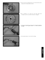
1
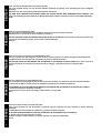
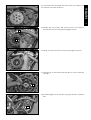
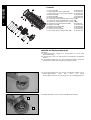
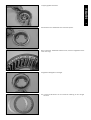
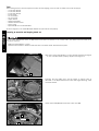
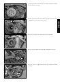
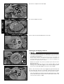
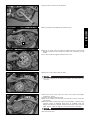
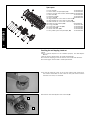
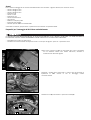
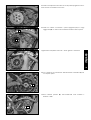
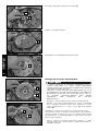
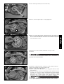
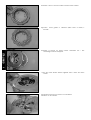
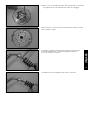
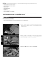
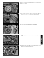
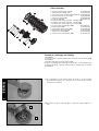
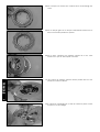
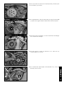
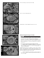
Information
Power Parts
77332000100
07. 2007
3.211.289
*3211289*
www.ktm.com
DEUTSCH
Danke, dass Sie sich für KTM Power Parts entschlossen haben.
Alle unsere Produkte wurden nach den höchsten Standards entwickelt und gefertigt, unter Verwendung der besten verfügbaren
Materialien.
KTM Power Parts sind rennerprobt und gewährleisten ultimative Performance.
KTM KANN NICHT VERANTWORTLICH GEMACHT WERDEN FÜR FALSCHE MONTAGE ODER VERWENDUNG DIESES PRODUKTS. Bitte
befolgen Sie die Montageanleitung. Wenn bei der Montage Unklarheiten auftreten, wenden Sie sich bitte an eine KTM Fachwerkstätte.
Danke.
ENGLISH
2
Thank you for choosing KTM Power Parts!
All of our products are designed and built to the highest standards using the finest materials available.
KTM Power Parts are race proven to offer the ultimate in performance.
KTM WILL NOT BE HELD LIABLE FOR IMPROPER INSTALLATION OR USE OF THIS PRODUCT. Please follow all instructions provided. If you
are unsure of any installation procedure, please contact a certified KTM dealer.
Thank you.
ITALIANO
2
Grazie per aver deciso di acquistare un prodotto KTM Power Parts.
Tutti i nostri prodotti sono stati sviluppati e realizzati secondo i massimi standard e con l'impiego dei migliori materiali disponibili.
Le KTM Power Parts sono collaudate nelle competizioni ed assicurano altissime prestazioni.
KTM NON PUÒ ESSERE RESA RESPONSABILE PER UN MONTAGGIO O USO IMPROPRIO DI QUESTO PRODOTTO. Per favore osservate le
istruzioni nel manuale d'uso.Se dovessero sorgere dei dubbi al montaggio, rivolgetevi ad un'officina specializzata KTM.
Grazie.
FRANCAIS
2
Nous vous remercions d'avoir choisi KTM Power Parts.
Tous nos produits ont été développés et réalisés selon les plus hauts standards et en utilisant les meilleurs matériaux disponibles.
Les Power Parts de KTM ont fait leurs preuves en compétition et garantissent les meilleures performances.
LA RESPONSABILITÉ DE KTM NE SAURAIT ÊTRE ENGAGÉE EN CAS D'ERREUR DANS LE MONTAGE OU L'UTILISATION DE CE PRODUIT.
Il convient de respecter les instructions de montage.
Si quelque chose n'est pas clair lors du montage, il faut s'adresser à un agent KTM.
Merci.
ESPANOL
2
2
Gracias por haberse decidido por el Power Parts KTM.
Todos nuestros productos han sido desarrollados y producidos según los estándares más altos utilizando los mejores materiales
disponibles.
Las KTM Power Parts están probadas en competencia y garantizan un óptimo rendimiento.
NO SE PUEDE HACER RESPONSABLE A LA KTM POR UN MONTAJE O UN USO INCORRECTO DE ESTE PRODUCTO.
Le rogamos seguir las instrucciones para el montaje.
Si durante el montaje resultan confusiones le rogamos contactar a un taller especializado KTM.
Gracias.
EINBAUANLEITUNG
EINBAUANLEITUNG
SORGFÄLTIG VOR
BEGINN
DER
ARBEIT
AM
MOTOR/FAHRZEUG
LESEN
Vorteile:
– Reduzierte Kupplungs-Betätigungskraft
– Verbesserte Dosierbarkeit der Kupplung beim Beschleunigen
– Kein Stempeln des Hinterrads beim Herunterschalten
– Verbesserte Lebensdauer von Motor und Getriebe durch Vermeidung von eingeleiteten Schlägen durch das Hinterrad
Durch das Anti-Hopping-System wird einerseits die Betätigungskraft reduziert und die Dosierung der Kupplung verbessert,
andererseits die Fahrstabilität durch Verringerung von Schlupf am Hinterrad bedingt durch die Motorbremswirkung während des
Herunterschaltens erhöht.
Das Anti-Hopping-System verwendet einen zweiteiligen Mitnehmer dessen beide Bauteile mit einer Schrägverzahnung verbunden
sind.
Bei hoher Motorbelastung (also großem Motordrehmoment) werden durch Verdrehung entsprechend der Schrägverzahnung die
beiden Bauteile des Mitnehmers gegeneinander gedrückt und damit die Kupplungsbeläge zusätzlich zu den Kupplungsfedern
aufeinander gepreßt. Durch diese zusätzliche Anpreßkraft können die Kupplungsfedern schwächer vorgespannt werden, damit tritt
beim Herunterschalten kurzzeitig Schlupf an der Kupplung auf und es wird Hinterradstempeln verhindert. Außerdem benötigen die
schwächeren Kupplungsfedern weniger Betätigungskraft, dies führt zu einer verbesserten Dosierbarkeit der Kupplung.
Anti-Hopping Einbau, Abstimmung und Wartung an KTM-Motorrädern der Serie 773
DER EINBAU
SOLLTE VON EINER AUTHORISIERTEN
FACHWERKSTATT
VORGENOMMEN WERDEN
HINWEIS:
– Die Charakteristik kann durch die Federvorspannkraft beeinflusst werden, ist aber stark abhängig vom Verwendungszweck
(Enduro, Motocross, Supermoto) und dem individuellen Fahrstil des Fahrers.
– Erhöhung der Federvorspannkraft bewirkt, dass die Kupplung beim Anbremsen später öffnet (mehr Motorbremswirkung).
Zusätzlich ändert sich auch das Eingreifen der Kupplung beim Starten, jedoch sind hier die Unterschiede wesentlich geringer
als beim Anbremsen. Die Kupplung wirkt etwas agressiver.
– Grundsätzlich immer von 0 Vorspannung ausgehen und dann in 0,5-1mm Schritten die Vorspannung erhöhen (Max 1,5 mm) bis
die optimale Einstellung für Sie persönlich gefunden wurde.
Lieferumfang:
1x
1x
1x
1x
1x
1x
1x
1x
1x
8x
8x
3x
3x
3x
Anti-Hopping-Kupplungssatz
Kupplungsfedern APTC komplett
Spezialmutter M18x1,5/Schnorrscheibe
Innere Nabe
Äußere Nabe
Druckkappe
AJ System komplett
Belaglamelle gedreht
Stahllamelle nitriert
Zwischenlamelle 1,4mm
Belaglamelle 2,7mm
Scheibe für Kupplungsfeder groß 13x18x1,5
Scheibe für Kupplungsfeder groß 13x18x1
Scheibe für Kupplungsfeder klein 5,5x12x1
77332000100
77332033044
77332032044
77332032010
77332032020
77332032090
77332032070
77332032060
77332032080
77332010000
77332011000
DEUTSCH
ANTI-HOPPING-SATZ FÜR KTM-MOTORRÄDER DER SERIE 773
3
Werkzeug
DEUTSCH
4
Für eine korrekte Montage des Anti-Hopping-Kupplungssatzes sind folgende Werkzeuge notwendig (nicht im Satz enthalten):
– 4 mm Inbusschlüssel
– 5 mm Inbusschlüssel
– 6 mm Inbusschlüssel
– 8 mm Stecknuß
– 13 mm Schlüssel
– 27 mm Stecknuß
– Drehmomentschlüssel
– Schmaler Schraubendreher
– Hammer und Flachmeißel
– Seegerringzange
– KTM-Spezialwerkzeug 773.29.003.000
außerdem Motoröl; Spezifikation und Menge siehe KTM-Reparaturanleitung.
Vorbereitung für die Montage des Anti-Hopping-Kupplungssatzes
DIE
FOLGENDEN VORBEREITUNGEN BETREFFEN ALLE KTM-MODELLE DER
EINER AUTHORISIERTEN FACHWERKSTATT VORGENOMMEN WERDEN.
SERIE 773
LAUT
ABSTIMMUNGSTABELLE. DIESE ARBEITEN
SOLLTEN VON
– Sauberen Arbeitsplatz sicherstellen.
– Wasser/Öl beständige Matte unter das Fahrzeug legen um Fahrzeugteile und Flüssigkeiten aufzunehmen.
Ölablaßschraube (1) mit einem 13 mm Schlüssel öffnen und das
auslaufende Motoröl mit einem geeigneten Behälter auffangen;
entsprechend entsorgen.
1
Fußbremshebel demontieren. Motor laut Reparaturanleitung auf ZündOT stellen und Motorblockierschraube 773.29.010.000 einsertzen.
Schrauben (2) lösen und Kupplungsdeckel (3) abnehmen.
2
2
3
2
DEUTSCH
Alle 6 Schrauben der Druckkappe über Kreuz lösen und zusammen mit
den Scheiben und Federn abnehmen.
5
Druckkappe (1) und Druckpilz (2) vorsichtig lösen und abnehmen.
Keinesfalls darf die Druckstange herausgezogen werden.
1
2
Alle Belag- und Zwischenlamellen aus dem Kupplungskorb nehmen.
Sicherungsblech der Zwischenwellenmutter (3) mit einem Flachmeißel
aufbiegen.
3
Spezialwerkzeug (4) 773.29.003.000 wie gezeigt aufsetzen und Mutter
lösen.
4
Mutter (1) und Sicherungsblech (2) abnehmen.
DEUTSCH
1
2
6
Mitnehmer (3) von der Welle ziehen.
3
HINWEIS: Die Scheibe (4) muss auf der Welle bleiben.
4
Montage Anti-Hopping-Kupplungssatz
–
5
6
DIE FOLGENDEN ARBEITEN BETREFFEN ALLE KTM-MODELLE DER SERIE 773.
DIESE ARBEITEN SOLLTEN VON EINER AUTHORISIERTEN FACHWERKSTATT
VORGENOMMEN WERDEN UND MÜSSEN STRIKT BEFOLGT WERDEN.
NABEN
UND
DIE
KUPPLUNGSLAMELLEN
SIND
MIT
3
– DIE
SICHERUNGSSCHRAUBEN M4 VORMONTIERT, DIESE DÜRFEN VOR DER MONTAGE
AM MOTOR NICHT ENTFERNT WERDEN, WENN DOCH, MUß DER ANTI-HOPPINGKUPPLUNGSSATZ ZUSAMMENGEBAUT WERDEN WIE IM KAPITEL WARTUNG
BESCHRIEBEN.
– Druckkappe vom Anti-Hopping-Kupplungssatz abnehmen.
– Anti-Hopping-Kupplungssatz am Motor montieren, wobei die
Verzahnung der Antriebswelle im inneren Anti-Hopping-Mitnehmer
und die Kupplungslamellen (5) im Kupplungskorb (6) eingreifen
müssen.
8
7
HINWEIS: um den Eingriff zu erleichtern, sollte der erste Gang
eingelegt und das Hinterrad leicht vor und zurück gedreht werden; falls
erforderlich können die Sicherungsschrauben M4 der Anti-HoppingEinheit eine halbe Umdrehung gelöst werden, damit die Bauteile
gegeneinander leicht beweglich sind.
– Gewinde der Antriebswelle und der Mutter reinigen und entfetten,
mit Loctite 243 bestreichen und mitgelieferte Schnorrscheibe (7)
sowie Mutter (8) montieren.
DEUTSCH
Mutter mit Loctite 243 sichern und mit 80 Nm anziehen.
7
Druckkappe (1) und Druckpilz montieren.
1
Die 3 Kupplungsfedern montieren, auf die Schrauben die
Unterlagscheiben und je nach Verwendung die erforderlichen
Kupplungsfeder-Scheiben (siehe Abbildung) aufschieben.
Schrauben eindrehen und über Kreuz mit 6,5 Nm anziehen.
Die 3 Sicherungsschrauben entfernen (Schrauben für spätere Arbeiten
gut aufbewahren).
–
DIE SICHERUNGSSCHRAUBEN
KUPPLUNG NICHT TRENNEN.
MÜSSEN ENTFERNT WERDEN, SONST KANN DIE
Kupplungsdeckel positionieren, Schrauben vom Kupplungsdeckel
einsetzen und über Kreuz mit 10 Nm festziehen.
Motorblockierschraube demontieren.
Fußbremshebel (25 Nm) und Kugelgelenkschraube (Loctite 243 und
10 Nm) montieren.
Verschraubung am Kupplungsdeckel entfernen und 1,3 Liter
vollsynthetisches Motoröl (Motorex Power Synt 4T 10W/50)
einfüllen. Motor starten alle Verschraubungen und Kupplungsdeckel
auf Dichtheit prüfen. Abschließend Motorölstand kontrollieren und
nötigenfalls berichtigen.
– ZU WENIG ODER QUALITATIV MINDERWERTIGES ÖL FÜHRT ZU
VORZEITIGEM VERSCHLEISS DES MOTORS.
Ersatzteile
DEUTSCH
1x
1x
1x
1x
1x
3x
3x
3x
3x
3x
8x
1x
8x
1x
1x
8
innere Nabe (1)
77332032010
Kupplungsfedern kompl. (2, 9, 11)
77332033044
Spezialmutter mit Schnorrscheibe (3, 4) 77332032044
äußere Nabe (5)
77332032020
Druckkappe (6)
77332032090
Sicherungsschraube (7)
59032007100
Scheibe für Kupplungsfeder groß 13x18x1,5 (8)
Scheibe für Kupplungsfeder groß 13x18x1 (8)
Scheibe für Kupplungsfeder klein 5,5x12x1 (10)
Schrauben für Kupplungsfedern (12)
0015050253
Belaglamelle (13)
77332011000
Belaglamelle gedreht (14)
77332032060
Zwischenlamelle (15)
77332010000
Stahllamelle nitriert (16)
77332032080
Anti-Judder System komplett (17, 18)
77332032070
WARTUNG Anti-Hopping-Kupplungssatz
HINWEIS:
Die Wartungsintervalle hängen vom Einsatzzweck ab; siehe KTMReparaturanleitung.
Die Wartung sollte von einer authorisierten Fachwerkstatt durchgeführt
werden.
Anti-Hopping-Kupplungssatz mit den Sicherungsschrauben blockieren
und ausbauen, Motor laut Reparaturanleitung blockieren.
Anti-Hopping-Kupplungssatz auf ebenem Untergrund auflegen und 2
Sicherungsschrauben
lösen.
Beim
Lösen
der
dritten
Sicherungsschraube wie im Bild gezeigt mit der Hand gegendrücken.
Die äußere Nabe (1) aus der inneren Nabe (2) herausnehmen.
1
2
DEUTSCH
Kupplungspaket abnehmen.
9
Anlaufscheibe und Judderfeder auf Verschleiß prüfen.
Beim Einbau der Judderfeder darauf achten, dass die aufgewölbte Seite
nach oben zeigt.
Ausgedrehte Belaglamelle auflegen.
Die nitrierte Stahllamelle hat eine dunklere Färbung als die übrigen
Lamellen.
Nitrierte Stahllamelle mit Stanzgrat nach unten aufsetzen.
DEUTSCH
10
Belaglamellen und Zwischenlamellen (Grat nach unten) aufsetzen und
ausrichten.
Kupplung auf innere Nabe aufsetzen. Darauf achten, dass sich beide
Markierungen decken.
Die Zapfen der äußeren Nabe müssen in die 3 Federn der inneren Nabe
einrasten.
Kupplung
mit
einem
Helfer
Sicherungsschrauben einschrauben.
zusammendrücken
und
DEUTSCH
Sicherungsschrauben so weit einschrauben, dass die Beläge zum
ausrichten (für den Einbau) beweglich sind.
11
Kupplung umdrehen. Die 4 Zapfen der inneren Nabe müssen, wie im
Bild gezeigt, mittig liegen.
Mit den mitgelieferten Scheiben kann die Vorspannung der AntiHopping-Kupplung eingestellt werden. Die große Scheibe (Stärke 1
und 1,5mm) erhöht die Vorspannung.
Die kleine Scheibe (Stärke 1mm) verringert die Vorspannung.
Allgemeine Hinweise:
DEUTSCH
–
–
–
–
–
–
–
–
12 –
–
–
–
–
–
–
–
–
Arbeiten nur an einem sauberen Arbeitsplatz durchführen.
Wird der Motor in geschlossenen Räumen gestartet, immer für entsprechende Belüftung und Abgasabsaugung sorgen.
Motorrad nur auf einem ebenen festen Untergrund mit einer geeigneten Vorrichtung anheben, im angehobenen Zustand sichern.
Arbeitskleidung und Werkstatt bzw. Werkstattausrüstung muß den gesetzlichen Vorschriften entsprechen.
Nichtauthorisierte Personen und Kinder aus dem Arbeitsbereich fernhalten.
Vor Arbeitsbeginn Motor abstellen und auskühlen lassen um Verbrennungen an heißen Teilen zu verhindern.
Vorsicht bei heißen Flächen und offenen Flammen, die meisten Flüssigkeiten wie Kraftstoff sind leicht brennbar bzw.
entwickeln giftige Dämpfe.
Ausgelaufenen Flüssigkeiten müssen entsprechend entsorgt werden.
Die nicht bestimmungsgerechte Verwendung von Anti-Hopping-Teilen ist nicht zulässig.
Vor der Montage prüfen, ob der Anti-Hopping-Kupplungssatz vollständig und beschädigungsfrei ist.
Fahrzeugzustand vor der Montage des Anti-Hopping-Kupplungssatz überprüfen.
Es wird speziell darauf hingewiesen, daß alle Sicherheitsvorschriften zu beachten sind, für aus fehlerhafter Montage
resultierende Schäden und Verletzungen wird nicht gehaftet. Bei unsachgemäßer Verwendung, falscher Montage und
Modifikationen wird keine Garantie übernommen.
Die beschriebene Funktion gilt nur für Fahrzeuge in Originalzustand, die keine Mängel oder Veränderungen aufweisen.
KTM behält sich das Recht vor, Änderungen am Produkt wie auch an der Dokumentation nach eigener Entscheidung
vorzunehmen.
Der Anti-Hopping-Kupplungssatz beinhaltet eine Mehrscheibenkupplung als Fahrzeugbestandteil, für den möglicherweise eine
Homologation nach den jeweiligen lokalen Gesetzen notwendig ist.
Der Anti-Hopping-Kupplungssatz wurde durch den Fahrzeughersteller geprüft.
Nach der Montage des Anti-Hopping-Kupplungssatzes ist möglicherweise eine Neu-Homologation des Fahrzeugs notwendig.
ANTI-HOPPING-SET FOR KTM SERIES 773 MOTORCYCLES
MOUNTING INSTRUCTIONS
READ
THE MOUNTING INSTRUCTIONS BEFORE STARTING TO WORK ON THE ENGINE/VEHICLE
Advantages:
– Reduced clutch actuating force
– Improved controllability of the clutch when accelerating
– No rear wheel hopping when shifting down
– Prolonged service life of the engine and transmission by avoiding applied impact from the rear wheel
The anti-hopping system uses a two-piece driver whose components are connected by helical gears.
At a high engine load (i.e. high engine torque) the two driver components are pressed against each other by turning in accordance
with the helical gears, causing the clutch linings as well as the clutch springs to be pressed together. This additional pressure force
makes it possible to reduce the clutch spring preload, slip on the clutch briefly occurs when shifting down and prevents rear wheel
hopping. The weaker clutch springs also require less actuating power, resulting in an improved controllability of the clutch.
Installing the anti-hopping clutch, tuning and service for KTM series 773 motorcycles
THE
ENGLISH
The anti-hopping system reduces the actuating force and improves the controllability of the clutch while increasing the driving
stability by reducing rear wheel hopping when shifting down by means of the engine braking effect.
ANTI-HOPPING CLUTCH SHOULD BE INSTALLED BY AN AUTHORIZED WORKSHOP.
13
NOTE:
– The characteristics can be influenced by the spring preload but are highly dependent on the intended purpose (Enduro,
Motocross, Supermoto) and the driver's personal style of driving.
– Increasing the spring preload delays the opening of the clutch when braking (higher engine braking effect). The clutch also
engages differently when starting but this difference is not as notable as the difference when braking. The clutch feels slightly
more aggressive.
– Generally always proceed from 0 preload and increase the preload in 0.5 - 1 mm increments (max. 1.5 mm) until you find the
setting that's right for you
Scope of supply:
1x
1x
1x
1x
1x
1x
1x
1x
1x
8x
8x
3x
3x
3x
anti-hopping-clutch set
anti-hopping clutch springs, complete
Special M18x1.5 nut/anti-vibration washer
Inner hub
Outer hub
Pressure cap
AJ System complete
Lining disk, machined
Nitride steel disk
Clutch disk 1.4mm
Lining disk 2.7mm
Large washer for clutch disk, 13x18x1,5
Large washer for clutch disk, 13x18x1
Small washer for clutch disk, 5,5x12x1
77332000100
77332033044
77332032044
77332032010
77332032020
77332032090
77332032070
77332032060
77332032080
77332010000
77332011000
Tools
The following tools will also be required to mount the anti-hopping clutch set (not included in the scope of supply):
– 4 mm Allan wrench
– 5 mm Allan wrench
– 6 mm Allan wrench
– 8 mm socket
– 13 mm wrench
– 27 mm socket
– torque wrench
– Narrow screwdriver
– Hammer and flat chisel
– Circlip pliers
– Special KTM tool 773.29.003.000
as well as engine oil, see the KTM Repair Manual for specification and quantity.
Preparing to mount the anti-hopping clutch set
ENGLISH
THE FOLLOWING PREPARATIONS APPLY TO
AUTHORIZED WORKSHOP.
KTM
SERIES
773
MODELS ACCORDING TO THE TUNING CHART.
THIS
WORK SHOULD BE DONE BY AN
– Make sure the workplace is clean.
– Spread a mat resistant to water/oil under the vehicle to absorb fluids and hold vehicle parts.
14
Open the oil drain plug (1) with a 13 mm wrench and drain the engine
oil into a suitable vessel; properly dispose of the engine oil.
1
Dismount the foot brake lever. Set the engine to ignition TDC as
described in the Repair Manual and insert the engine blocking screw
773.29.010.000.
Loosen the screws (2) and remove the clutch cover (3).
2
2
3
2
Loosen the 6 screws on the pressure cap crosswise and remove together
with the washers and springs.
Carefully loosen and remove the pressure cap (1) and pressure piece
(2). Make sure the pushrod stays in place.
ENGLISH
1
2
15
Remove all lining and clutch disks from the outer clutch hub.
Bend up the lock washer on the idler shaft nut (3) with a flat chisel.
3
Apply the special tool (4) 773.29.003.000 as illustrated and loosen
the nut.
4
Remove the nut (1) and lock washer (2).
1
2
Pull the driver (3) off the shaft.
ENGLISH
3
16
NOTE: make sure the washer (4) stays on the shaft.
4
Mounting the anti-hopping clutch set
–
5
6
THE FOLLOWING WORK APPLIES TO ALL KTM MODELS IN THE 773 SERIES.
THIS WORK SHOULD BE PERFORMED BY AN AUTHORIZED WORKSHOP, STRICTLY
FOLLOWING THE INSTRUCTIONS.
– THE HUBS AND THE CLUTCH DISKS ARE PRE-MOUNTED WITH THREE M4 LOCK
SCREWS. DO NOT REMOVE THEM FROM THE ENGINE PRIOR TO MOUNTING. IF
THEY ARE REMOVED, THE ANTI-HOPPING CLUTCH SET MUST BE ASSEMBLED AS
DESCRIBED IN THE "MAINTENANCE" CHAPTER.
– Remove the pressure cap and the pressure piece from the antihopping clutch set.
– Mount the anti-hopping clutch set on the engine. Make sure the
toothing on the main shaft engages in the inner anti-hopping driver
and the clutch disks (5) engage in the outer clutch hub (6)
NOTE: it will be easier to mount if you engage first gear and slowly turn
the rear wheel back and forth; if necessary, loosen the M4 lock screws
on the anti-hopping unit half a turn to make the components movable.
8
7
– Clean and degrease the thread on the main shaft and the nut. Apply
Loctite 243 and mount the anti-vibration washer (7) included in the
scope of supply and the nut (8).
Torque the nut (Loctite 243 and 80 Nm).
ENGLISH
Mount the pressure cap (1) and the pressure piece.
1
17
Mount the 3 clutch disks and slide the washers and the clutch spring
washers required for the respective model (see illustration) on the
screws.
Turn in the screws and tighten crosswise to 6.5 Nm.
Remove the 3 lock screws (save for later).
–
THE
LOCK SCREWS MUST BE REMOVED OTHERWISE THE CLUTCH WILL NOT
DISENGAGE.
Position the clutch cover, insert the clutch cover screws and tighten
crosswise to 10 Nm.
Dismount the engine blocking screw.
Mount the foot brake lever (25 Nm) and the ball screw (Loctite 243
and 10 Nm).
Remove the screw cap from the clutch cover and add 1,3 liters of fullysynthetic engine oil (Motorex Power Synt 4T 10W/50). Start the
engine and check all screwed connections and the clutch cover for
leaks. Finally, check the engine oil level and correct if necessary.
–
NOT ENOUGH ENGINE OIL OR LOW-GRADE ENGINE OIL WILL CAUSE
PREMATURE ENGINE WEAR.
Spare parts
1x Inner hub (1)
77332032010
1x Clutch disks, complete (2, 9, 11)
77332033044
1x Special nut with anti-vibration washer (3, 4) 77332032044
1x Outer hub (5)
77332032020
1x Pressure cap (6)
77332032090
3x Lock screw (7)
59032007100
3x Large washer for clutch disk 13x18x1.5 (8)
3x Large washer for clutch disk 13x18x1 (8)
3x Small washer for clutch disk 5.5x12x1 (10)
3x Screws for clutch disks (12)
0015050253
8x Lining disk (13)
77332011000
1x Lining disk, machined (14)
77332032060
8x Clutch disk (15)
77332010000
1x Nitride steel disk (16)
77332032080
1x Anti-judder system complete (17, 18)
77332032070
ENGLISH
18
Servicing the anti-hopping clutch set
NOTE:
Service intervals depend on the intended purpose; see KTM Repair
Manual.
Have the service performed by an authorized workshop.
Block the anti-hopping clutch set with the lock screws and dismount.
Block the engine as described in the Repair Manual.
Place the anti-hopping clutch set on an even surface and loosen the 2
lock screws. Press down on the clutch set with your hand to remove
the third lock screw, as illustrated.
Remove the outer hub (1) from the inner hub (2).
1
2
Remove the clutch pack.
ENGLISH
Check the stop disk and judder spring for wear.
19
When remounting the judder spring, make sure the cambered side points
up.
Mount the machined lining disk.
The nitrided steel disk is darker than the other disks.
Mount the nitrided steel disk with the punched burr facing down.
Mount the lining disks and clutch disks (burr facing down) and align.
ENGLISH
20
Mount the clutch on the inner hub. Make sure the two alignment marks
coincide.
The pins in the outer hub must engage in the 3 springs on the inner
hub.
Have someone press the clutch together and turn in the lock screws.
When turning in the lock screws, make sure they can still be moved for
alignment (when they are mounted).
ENGLISH
Turn the clutch over. The 4 pins on the inner hub must be centered, as
illustrated.
21
The anti-hopping clutch preload can be adjusted with the washers
included in the scope of supply. The big washer (1 and 1.5mm
thick) increase the preload.
The small washer (1mm thick) reduces the preload.
General information:
-
ENGLISH
22
-
Only work at a clean workplace.
If starting the engine in an enclosed room, provide for adequate ventilation and emissions extraction.
Always jack up the motorcycle with a suitable device on a firm and level surface and secure when raised.
The working clothes, the workshop and the workshop equipment must comply with the legal regulations.
Keep unauthorized persons and children away from the work area.
Switch off the engine and allow to cool down before starting to work to avoid being burned by hot components.
Keep hot surfaces away from open fire; many liquids such as fuel are highly combustible and can develop toxic vapors.
Properly dispose of any drained fluids.
The use of the anti-hopping components for purposes other than the intended purpose is prohibited.
Check whether the anti-hopping clutch set is complete and undamaged prior to mounting.
Check the vehicle condition before mounting the anti-hopping clutch set.
We specifically emphasize that all safety regulations must be observed; no liability will be assumed for damage or injuries arising
from improper mounting. The warranty will become null and void in cases of improper use, incorrect mounting or any
modifications.
The described function only applies to vehicles in their original condition without any defects or modifications.
KTM reserves the right to modify the product or the documentation.
The anti-hopping clutch set is a multidisk clutch and vehicle component for which a type approval may be required under the
local law.
The anti-hopping clutch was tested by the vehicle manufacturer.
Rehomologation of the vehicle may be required after the anti-hopping clutch set is mounted.
KIT FRIZIONE ANTISALTELLAMENTO PER MOTOCICLETTE KTM SERIE 773
ISTRUZIONI DI MONTAGGIO
LEGGERE ATTENTAMENTE LE ISTRUZIONI DI MONTAGGIO PRIMA DI PROCEDERE AI LAVORI SUL MOTORE/VEICOLO
Vantaggi:
– ridotto sforzo alla leva frizione
– miglior modulabilità della frizione all'accelerazione
– niente saltellamento della ruota posteriore in fase di scalata delle marce
– maggiore durata del motore e del cambio grazie ai ridotti colpi della ruota posteriore
Il sistema antisaltellamento riduce da un lato lo sforzo da applicare alla leva e migliora la modulabilità della frizione, dall'altro
aumenta la stabilità di guida riducendo lo slittamento della ruota posteriore dovuto all'effetto frenante del motore durante la
scalata delle marce.
Il sistema antisaltellamento impiega un mozzo costituito da due parti collegate tra loro attraverso una dentatura obliqua.
Ad alto carico del motore (e quindi ad alta coppia) i due componenti del mozzo, girandosi in corrispondenza della dentatura
obliqua, vengono pressati l'uno contro l'altro comprimendo oltre alle molle frizione anche i dischi guarniti. Attraverso questa
addizionale forza di pressione è sufficiente meno precarico delle molle frizione, così alla scalata delle marce si verifica un breve
slittamento della frizione che previene il saltellamento della ruota posteriore. Le molle frizione più morbide richiedono inoltre meno
sforzo alla leva dal che consegue anche una miglior modulabilità della frizione.
Montaggio, taratura e manutenzione della frizione antisaltellamento su motociclette KTM serie 773
NOTA BENE:
– La caratteristica può essere influenzata dalla forza di precarico della molla, tuttavia varia fortemente in funzione dell'impiego
previsto (Enduro, Motocross, Supermoto) e dello stile di guida individuale del conducente.
– Una maggiore forza di precarico della molla comporta l'apertura ritardata della frizione in fase di frenata (aumento dell'azione
frenante del motore). Inoltre varia anche l'innesto della frizione all'avviamento, ma in questo caso le differenze sono minori
rispetto alla fase di frenata. La frizione risulterà un po' più aggressiva.
– Di norma partire sempre da un precarico di 0 e poi aumentare il precarico con incrementi di 0,5-1 mm (max. 1,5 mm) fino a
ottenere la personale regolazione ottimale.
ITALIANO
IL MONTAGGIO DOVREBBE ESSERE ESEGUITO DA UN'OFFICINA AUTORIZZATA.
23
Volume della fornitura:
N.
N.
N.
N.
N.
N.
N.
N.
N.
N.
N.
N.
N.
N.
1
1
1
1
1
1
1
1
1
8
8
3
3
3
kit frizione antisaltellamento
molla frizione APTC completa
dado speciale M18x1,5/rondella Schnorr
mozzo interno
mozzo esterno
piatto spingidisco
sistema AJ completo
disco guarnito ripassato
disco frizione in acciaio nitrurato
dischi intermedi 1,4mm
disco frizione guarnito 2,7mm
rondelle per molle frizione grandi 13x18x1,5
rondelle per molle frizione grandi 13x18x1
rondelle per molle frizione piccole 5,5x12x1
77332000100
77332033044
77332032044
77332032010
77332032020
77332032090
77332032070
77332032060
77332032080
77332010000
77332011000
Atrezzi:
Per il corretto montaggio del kit frizione antisaltellamento sono necessari i seguenti attrezzi (non contenuti nel kit):
– Chiave a brugola 4 mm
– Chiave a brugola 5 mm
– Chiave a brugola 6 mm
– Bussola 8 mm
– Chiave 13 mm
– Bussola 27 mm
– Chiave dinamometrica
– Cacciavitino
– Martello e scalpello piatto
– Pinza per anelli Seeger
– Attrezzo speciale KTM 773.29.003.000
inoltre dell'olio motore; per specifiche e quantità vedi nel manuale di riparazione KTM.
Preparativi per il montaggio del kit frizione antisaltellamento
LE OPERAZIONI PRELIMINARI RIPORTATE DI SEGUITO RIGUARDANO TUTTI I MODELLI KTM SERIE 773 COME DA TABELLA
DI TARATURA. QUESTI LAVORI DOVREBBERO ESSERE ESEGUITI DA UN'OFFICINA AUTORIZZATA.
– Provvedere ad un posto di lavoro pulito.
– Stendere una stuoia resistente all'acqua/olio sotto il veicolo per raccogliere i pezzi ed i liquidi della moto.
ITALIANO
Aprire la vite di scarico olio (1) con una chiave da 13 mm e raccogliere
con un serbatoio idoneo l'olio motore fuoriuscito; smaltirlo in
conformità alla normativa vigente.
1
24
Smontare il pedale freno. Posizionare il motore come da manuale di
riparazione al PMS inserire la vite di bloccaggio motore
773.29.010.000.
Allentare le viti (2) e rimuovere il coperchio frizione (3).
2
2
3
2
Allentare con sequenza a croce tutte le 6 viti del piatto spingidisco e rimuoverle insieme alle rondelle e alle molle.
Allentare con cautela e rimuovere il piatto spingidisco (1) e il fungo
reggispinta (2). In nessun caso è ammesso estrarre l'asta di spinta.
1
2
ITALIANO
Togliere dalla campana frizione tutti i dischi guarniti e intermedi.
25
Aprire la piastrina di sicurezza del dado dell'albero intermedio (3) con
un scalpello piatto.
3
Inserire l'attrezzo speciale (4) 773.29.003.000 come mostrato e
allentare il dado.
4
Rimuovere il dado (1) e la piastrina di sicurezza (2).
1
2
Estrarre il mozzo (3) dall'albero.
3
NOTA BENE: La rondella (4) deve restare sull'albero.
ITALIANO
4
26
Montaggio del kit frizione antisaltellamento
–
5
6
I LAVORI RIPORTATI DI SEGUITO RIGUARDANO TUTTI I
MODELLI KTM SERIE 773. QUESTI LAVORI DOVREBBERO
ESSERE ESEGUITI DA UN'OFFICINA AUTORIZZATA ED ESEGUITI
ESATTAMENTE COME INDICATO.
– I MOZZI ED I DISCHI FRIZIONE SONO PREMONTATI CON 3 VITI
DI SICUREZZA M4 CHE NON DEVONO ESSERE TOLTE PRIMA DEL
MONTAGGIO NEL MOTORE. NEL CASO SIANO STATE TOLTE, IL
KIT
FRIZIONE
ANTISALTELLAMENTO
DEVE
ESSERE
ASSEMBLATO
COME
DESCRITTO
NEL
CAPITOLO
MANUTENZIONE.
– Rimuovere il piatto spingidisco del kit frizione antisaltellamento.
– Montare il kit frizione antisaltellamento sul motore, considerando
che la dentatura dell'albero primario deve innestarsi nel mozzo
interno antisaltellamento e i dischi frizione (5) nella campana
frizione (6).
8
7
NOTA BENE: Per facilitare l'inserimento, innestare la prima marcia
e muovere in un senso e nell'altro la ruota posteriore; all'occorrenza è
possibile allentare di mezzo giro le viti di sicurezza M4 del gruppo
antisaltellamento, in modo da guadagnare la possibilità di movimento
reciproco dei componenti.
– Pulire e sgrassare la filettatura dell'albero primario e il dado,
applicare Loctite 243, quindi montare la rondella Schnorr (7) e il
dado (8) in dotazione.
Serrare il dado applicando (Loctite 243 e80 Nm).
Montare il piatto spingidisco (1) e il fungo reggispinta.
Montare le 3 molle della frizione, applicare gli anelli di spessore sulle
viti e, a seconda dell'utilizzo, le necessarie rondelle delle molle
frizione (vedere illustrazione). Avvitare le viti e serrarle in sequenza a
croce applicando 6,5 Nm.
ITALIANO
1
27
Rimuovere le 3 viti di sicurezza (conservare le viti per i lavori
successivi).
– LE VITI DI SICUREZZA DEVONO ESSERE TOLTE, ALTRIMENTI LA
FRIZIONE NON PUÒ STACCARE.
Posizionare il coperchio frizione, inserire le viti del coperchio frizione
e serrare in sequenza a croce applicando 10 Nm.
Smontare la vite di bloccaggio motore
Montare il pedale freno (25 Nm) e la vite del giunto sferico (Loctite
243 e10 Nm).
Rimuovere il raccordo filettato in corrispondenza del coperchio frizione
e versare 1,3 litri di olio motore completamente sintetico (Motorex
Power Synt 4T 10W/50). Avviare il motore e controllare la tenuta
ermetica di tutti i raccordi filettati e del coperchio frizione. Infine
controllare il livello dell'olio motore e, se necessario, correggerlo.
–
UNA QUANTITÀ TROPPO ESIGUA DI OLIO O OLIO DI
SCARSA QUALITÀ PROVOCA UN'USURA PRECOCE DEL MOTORE.
Parti di ricambio
N. 1 mozzo interno (1)
77332032010
N. 1 molla frizione compl. (2, 9, 11)
77332033044
N. 1 dado speciale con rondella Schnorr (3, 4) 77332032044
N. 1 mozzo esterno (5)
77332032020
N. 1 piatto spingidisco (6)
77332032090
N. 3 viti di sicurezza (7)
59032007100
N. 3 rondelle per molle frizione grandi 13x18x1,5 (8)
N. 3 rondelle per molle frizione grandi 13x18x1 (8)
N. 3 rondelle per molle frizione piccole 5,5x12x1 (10)
N. 3 viti per molle frizione (12)
0015050253
N. 8 dischi frizione guarniti (13)
77332011000
N. 1 disco guarnito ripassato (14)
77332032060
N. 8 dischi intermedi (15)
77332010000
N. 1 disco frizione in acciaio nitrurato (16) 77332032080
N. 1 sistema Anti-Judder completo (17, 18) 77332032070
MANUTENZIONE Kit frizione antisaltellamento
ITALIANO
NOTA BENE:
Gli intervalli di manutenzione dipendono dal tipo d'impiego; vedi
Manuale di riparazione KTM.
La manutenzione dovrebbe essere eseguita da un'officina autorizzata.
Bloccare il kit frizione antisaltellamento con le viti di sicurezza e
smontarlo. Poi bloccare il motore come da Manuale di riparazione.
28
Posare il kit frizione antisaltellamento su una superficie piana e
allentare 2 viti di sicurezza. Per allentare la terza vite di sicurezza
girare a mano come mostrato in figura.
Estrarre il mozzo esterno (1) dal mozzo interno (2).
1
2
Rimuovere il pacco frizione.
Controllare che l'anello di spinta e la molla Judder non siano usurati.
ITALIANO
In fase di montaggio della molla Judder, tenere conto della grana,
come mostrato in figura.
29
Applicare il disco guarnito con diametro interno grande.
Il disco in acciaio nitrurato presenta una colorazione più scura rispetto
agli altri dischi.
Sistemare il disco in acciaio nitrurato con bava rivolta in basso.
Applicare i dischi guarniti e intermedi (bava rivolta in basso) e
allinearli.
Sistemare la frizione sul mozzo interno. Controllare che i due
contrassegni risultino sovrapposti.
ITALIANO
30
I perni del mozzo esterno devono ingranare nelle 3 molle del mozzo
interno.
Comprimere la frizione con l'ausilio di un aiutante e
avvitare le viti di sicurezza.
Avvitare le viti di sicurezza lasciando ancora possibilità di movimento
alle guarnizioni per l'allineamento (per la fase di montaggio).
Le rondelle in dotazione consentono di regolare il precarico della
frizione antisaltellamento. La rondella più grande (spessore 1
e 1,5 mm) aumenta il precarico.
ITALIANO
Girare la frizione. I 4 perni del mozzo interno devono trovarsi al centro,
come mostrato in figura.
31
La rondella più piccola (spessore 1mm) riduce il precarico.
Avvertenze generali:
-
Eseguire i lavori solo ad un posto di lavoro pulito.
Se si avvia il motore in locali chiusi, provvedere sempre ad una sufficiente aerazione ed aspirazione dei gas di scarico.
Alzare la moto solo su un fondo piano e solido mediante un dispositivo adatto ed assicurarla nella posizione alzata.
Gli indumenti di lavoro nonché l'officina e l'attrezzatura dell'officina devono essere conformi alle relative disposizioni di legge.
Tener fuori dalla zona di lavoro le persone non autorizzate ed i bambini.
Prima di iniziare il lavoro, spegnere il motore e farlo raffreddare per evitare scottature su parti calde.
Attenzione con superfici calde e fiamme aperte, la maggior parte dei liquidi e il carburante sono facilmente infiammabili o
sviluppano vapori tossici.
- I liquidi fuoriusciti devono essere raccolti e smaltiti regolarmente.
12 - Non è consentito un uso diverso da quello previsto dei componenti della frizione antisaltellamento.
- Prima del montaggio verificare che il kit frizione antisaltellamento sia completo e privo di danneggiamenti.
- Verificare le condizioni del veicolo prima di montare il kit frizione antisaltellamento.
- Si raccomanda espressamente di osservare tutte le disposizioni di sicurezza. Non si risponde per danni o lesioni dovuti ad un
montaggio non corretto. Non ci si assume alcuna garanzia in caso di uso improprio, montaggio non corretto o modifiche
apportate.
- La funzione descritta vale solo per veicoli allo stato originale che non presentano difetti o modifiche.
- KTM si riserva il diritto di apportare a propria discrezione modifiche al prodotto e alla documentazione.
- Il kit frizione antisaltellamento comprende una frizione multidisco e quindi un componente del veicolo per il quale
è eventualmente necessaria un'omologazione secondo le normative locali.
- Il kit frizione antisaltellamento è stato testato ed approvato dal costruttore dei veicoli.
- Dopo il montaggio della frizione antisaltellamento potrebbe essere richiesta una nuova omologazione del veicolo.
ITALIANO
32
KIT ANTI-DRIBBLING POUR MOTOS KTM DE LA SÉRIE 773
NOTICE DE MONTAGE
IL
CONVIENT DE LIRE ATTENTIVEMENT LA NOTICE DE MONTAGE AVANT DE COMMENCER LE TRAVAIL
Avantages:
– Poignée d'embrayage plus douce
– Meilleur dosage de l'embrayage à l'accélération
– Pas de dribbling de la roue arrière au rétrogradage
– Fiabilité accrue du moteur et de la boîte en raison de l'absence de chocs induits par la roue arrière
Le système anti-dribbling permet de réduire la force nécessaire pour actionner l'embrayage, il en facilite également le dosage et,
d'autre part, il accroît la stabilité de la moto en réduisant la perte d'adhérence de la roue arrière provoquée par le frein moteur lors
du rétrogradage.
Le système utilise une noix double avec un accouplement oblique. Quand le moteur entraîne fort (couple moteur important)
l'accouplement oblique provoque un décalage et une pression supplémentaire sur les disques, qui vient s'ajouter à la pression des
ressorts. Cette pression supplémentaire permet d'utiliser des ressorts plus faibles, ce qui fait qu'au rétrogradage se produit un bref
patinage qui empêche la roue arrière de sautiller. De plus la faiblesse des ressorts fait qu'on a besoin de moins de force pour
actionner la poignée d'embrayage, ce qui permet aussi de doser de manière plus fine.
Montage du système anti-dribbling, réglage et entretien sur les motos KTM de la série 773
LE
MONTAGE DOIT ÊTRE RÉALISÉ DANS UN ATELIER AGRÉÉ
NOTA BENE:
– Les caractéristiques peuvent être influencées par la précontrainte des ressorts, mais se déterminent d'après l'utilisation (enduro,
motocross ou supermotard) et en fonction du style du pilote.
– Quand on augmente la précontrainte, on provoque un glissement plus tardif de l'embrayage au rétrogradage (plus de frein
moteur). De plus l'attaque de l'embrayage au départ change aussi, mais dans des proportions bien moindres que pour le
rétrogradage. L'embrayage est en quelque sorte plus agressif.
– Le principe veut que l'on parte toujours d'une précontrainte nulle pour augmenter ensuite graduellement par paliers de 0,5 à 1
mm pour arriver à un maximum de 1,5 mm. On déterminera ainsi le meilleur réglage personnel.
1
1
1
1
1
1
1
1
1
8
8
3
3
3
kit anti-dribbling
ensemble ressorts APTC
écrou spécial M18x1,5/rondelle Schnorr
élément intérieur de la noix
élément extérieur de la noix
plateau de pression
ensemble anti-vibration
disque garni réduit au tour
disque acier nitruré
disques intermédiaires 1,4 mm
disque garni 2,7 mm
rondelles pour ressort, grandes, 13x18x1,5
rondelles pour ressort, grandes, 13x18x1
rondelles pour ressort, petites, 5,5x12x1
77332000100
77332033044
77332032044
77332032010
77332032020
77332032090
77332032070
77332032060
77332032080
77332010000
77332011000
FRANCAIS
Kit de livraison:
33
Outillage
Pour pouvoir monter correctement l'embrayage, il convient de posséder l'outillage suivant (non compris dans le kit):
– Clef mâle pour six pans creux de 4 mm
– Clef mâle pour six pans creux de 5 mm
– Clef mâle pour six pans creux de 6 mm
– Douille de 8 mm
– Clef de 13 mm
– Douille de 27 mm
– Clef dynamométrique
– Tournevis fin
– Marteau et burin plat
– Pince à circlips
– Outil spécial KTM 773.29.003.000
Il faut ajouter à cela de l'huile. En ce qui concerne les spécifications et les quantités, voir le manuel de réparation.
Travaux préparatoires au montage de l'embrayage anti-dribbling
CES TRAVAUX PRÉPARATOIRES CONCERNENT TOUS LES MODÈLES
ÊTRE EFFECTUÉS DANS UN ATELIER AGRÉÉ.
KTM
DE LA SÉRIE
773
TELS QUE SPÉCIFIÉS DANS LE TABLEAU.
CES
TRAVAUX DOIVENT
– Le poste de travail doit être propre.
– Glisser un tapis adéquat sous la moto pour absorber les liquides et poser les pièces.
Avec une clef de 13 enlever le bouchon de vidange (1) et recueillir
dans un récipient adéquat l'huile qui s'écoule. Eliminer l'huile selon
la réglementation.
1
FRANCAIS
Démonter la pédale de frein. Mettre le moteur sur le point mort haut
d'allumage en suivant les prescriptions du manuel de réparation puis
visser la vis de blocage du moteur (773.29.010.000).
34
Enlever les vis (2) et retirer le couvercle d'embrayage (3).
2
2
3
2
Dévisser en croix les six vis du plateau de pression et les retirer avec les
rondelles et les ressorts.
Retirer le plateau de pression (1) et la pièce d'appui (2) avec
précaution. En aucun cas il ne faut retirer la tige d'embrayage.
1
2
Sortir de la cloche tous les disques garnis et intermédiaires.
FRANCAIS
Avec un burin plat, redresser la rondelle frein de l'écrou (3) en bout
d'arbre.
3
35
Mettre en place l'outil spécial (4) (773.29.003.000) comme cela est
indiqué sur l'illustration et desserrer l'écrou.
4
Retirer l'écrou (1) et la rondelle frein (2).
1
2
Sortir la noix (3).
3
NOTA BENE: La rondelle (4) doit rester sur l'arbre.
4
Montage du kit anti-dribbling
FRANCAIS
–
5
6
36
–
LES TRAVAUX DÉCRITS CI-APRÈS CONCERNENT TOUS LES MODÈLES KTM DE LA
SÉRIE 773. ILS DOIVENT ÊTRE EFFECTUÉS PAR UN ATELIER AGRÉÉ ET SUIVIS
STRICTEMENT.
LES DEUX ÉLÉMENTS DE LA NOIX ET LES DISQUES SONT PRÉASSEMBLÉS AU
MOYEN DE TROIS VIS M4. IL NE FAUT PAS RETIRER CES VIS AVANT QUE
L'EMBRAYAGE SOIT MIS EN PLACE. SI ON L'A FAIT NÉANMOINS, IL FAUT
RÉASSEMBLER L'ENSEMBLE COMME CELA EST DÉCRIT AU PARAGRAPHE
ENTRETIEN.
– Retirer le plateau de pression du kit.
– Monter le kit en veillant à ce que les cannelures del'arbre
correspondent à celles de l'élément intérieur de la noix et à ce que
les disques (5) prennent leur place dans la noix (6).
NOTA BENE: Pour faciliter la mise en place, il convient de passer la
première et de faire tourner légèrement la roue arrière dans les deux
sens. Si nécessaire, on peut desserrer d'un demi-tour les vis M4 tenant
l'ensemble afin de pouvoir faire bouger les différents éléments.
8
7
– Nettoyer et dégraisser les filetages de l'arbre et de l'écrou, y déposer
une goutte de loctite 243, mettre la rondelle Schnorr (7) et l'écrou
(8).
Serrer l'écrou à 80 Nm et Loctite 243.
Monter le plateau de pression (1) et la pièce d'appui pour la tige.
1
Mettre en place les trois ressorts, enfiler sur les vis les rondelles
d'appui ainsi que les rondelles de dureté choisies (voir illustration).
Visser les vis et les serrer progressivement à 6,5 Nm.
–
IL
FAUT ENLEVER LES TROIS VIS DE MONTAGE, SINON L'EMBRAYAGE NE PEUT
PAS FONCTIONNER.
FRANCAIS
Retirer les trois vis de montage (les garder de côté pour des travaux
futurs).
37
Présenter le couvercle d'embrayage, mettre les vis et les serrer en croix
à 10 Nm.
Démonter la vis de blocage du moteur
Monter la pédale de frein (25 Nm) et la rotule (loctite 243 et 10 Nm).
Retirer le bouchon sur le couvercle et mettre 1,3 litre d'huile moteur
de synthèse (Motorex Power Synt 4T 10W/50). Faire démarrer le
moteur et vérifier l'étanchéité au niveau des vis et du couvercle.
Vérifier le niveau d'huile moteur et corriger si nécessaire.
– UN
MANQUED'HUILE OU UNE HUILE DE BASSE QUALITÉ PROVOQUENT UNE
USURE PRÉMATURÉE DU MOTEUR.
Pièces détachées
1
1
1
1
1
3
3
3
3
3
8
1
8
1
1
élément intérieur de la noix (1)
77332032010
ensemble ressort (2, 9, 11)
77332033044
écrou spécial avec rondelle Schnorr (3, 4) 77332032044
élément extérieur de la noix (5)
77332032020
plateau de pression (6)
77332032090
vis de montage (7)
59032007100
rondelles pour ressort, grandes, 13x18x1,5 (8)
rondelles pour ressort, grandes, 13x18x1 (8)
rondelles pour ressort, petites, 5,5x12x1 (10)
vis pour ressort d'embrayage (12)
0015050253
disques garnis (13)
77332011000
disque garni réduit au tour (14)
77332032060
disques intermédiaires (15)
77332010000
disque acier nitruré (16)
77332032080
ensemble anti-vibration (17, 18)
77332032070
Entretien de l'embrayage anti-dribbling
NOTA BENE:
La périodicité de l'entretien dépend de l'utilisation. Voir le manuel KTM
de réparation.
L'entretien doit être fait par un atelier agréé.
Bloquer l'embrayage anti-dribbling au moyen des vis de montage pour
le déposer. Bloquer le moteur comme cela est indiqué dans le manuel
de réparation.
FRANCAIS
Poser l'embrayage sur une surface plane et retirer 2 vis de montage.
Pour retirer la troisième vis, appuyer avec la main comme cela est
montré sur l'illustration.
38
Désaccoupler l'élément extérieur (1) et l'élément intérieur (2) de la
noix.
1
2
Retirer l'ensemble des disques.
Vérifier si la rondelle et le ressort anti-vibration ne présentent pas de traces d'usure.
Quand on remonte le ressort anti-vibration, tenir compte du coup de pointeau, comme cela est indiqué sur l'illustration.
FRANCAIS
Mettre le disque garni réduit au tour.
39
Le disque acier nitruré a une coloration plus foncée que les autres disques.
Mettre le disque acier nitruré avec la bavure due à l'emboutissage vers
le bas.
Mettre les disques garnis et les disques intermédiaires (bavure vers le
bas) en leur faisant prendre leur position.
Mettre en place l'ensemble sur l'élément intérieur de la noix. Faire
attention à ce que les deux repères coïncident.
Les trois tétons de l'élément extérieur doivent prendre dans les trois
ressorts de l'élément intérieur.
FRANCAIS
40
Faire comprimer l'embrayage par un aide de manière à pouvoir mettre
en place les vis de montage.
Visser les vis de montage de manière à ce que les disques puissent
encore être bougés pour permettre le montage.
Retourner l'embrayage. Les 4 tétons de l'élément intérieur doivent se
situer au milieu de la fenêtre, comme cela est indiqué sur
l'illustration.
Les rondelles faisant partie du kit permettent de régler la précontrainte
de l'embrayage. Avec les grandes rondelles (épaisseur 1 mm ou 1,5
mm) on augmente la précontrainte.
FRANCAIS
Les petites rondelles (épaisseur 1 mm) réduisent la précontrainte.
41
Remarques générales:
- Le poste de travail doit être d'une grande propreté.
- Si l'on fait tourner le moteur dans un lieu clos, il faut veiller à ce qu'il y ait une aération suffisante et une extraction des gaz
d'échappement.
- Mettre la moto sur une surface plane et dure et la lever avec un dispositif adéquat. La fixer quand elle est en position levée.
- La tenue de travail, le local et l'équipement doivent respecter les dispositions légales.
- Les personnes non autorisées et les enfants ne doivent pas avoir accès au lieu de travail.
- Avant de procéder aux travaux, couper le moteur et le laisser refroidir pour éviter de se brûler.
- Faire attention aux éléments chauds et si l'on utilise une flamme nue. La plupart des liquides tels le carburant s'enflamment
facilement et dégagent des gaz toxiques.
- Les liquides de vidange doivent être éliminés selon les normes en vigueur.
- Il n'est pas licite d'utiliser des éléments de l'embrayage anti-dribbling pour autre chose que le but défini.
- Avant de procéder au montage, vérifier que l'embrayage anti-dribbling est complet et en bon état.
- Avant de procéder au montage de l'embrayage anti-dribbling, vérifier l'état de la moto.
- L'attention est particulièrement attirée sur le fait qu'il faut respecter scrupuleusement les consignes de sécurité. Il ne peut y avoir
aucun recours pour des dégâts ou des blessures qui résulteraient d'un montage défectueux. Pareillement la garantie ne pourrait
être invoquée en cas d'utilisation fautive, de montage défectueux ou de modifications.
- Le fonctionnement tel qu'il est décrit ne concerne que des motos d'origine, en parfait état et n'ayant subi aucune modification.
- KTM se réserve le droit exclusif de modifier le produit et la documentation.
- Le kit anti-dribbling a comme composant un embrayage multidisque qui fait partie intégrante du véhicule et pour lequel il est
possible que les lois en vigueur localement exigent une homologation.
- Le kit anti-dribbling a été testé par le fabriquant du véhicule.
- Après montage du kit anti-dribbling il est possible qu'une nouvelle homologation du véhicule soit nécessaire.
FRANCAIS
42
JUEGO ANTI-REBOTE PARA MOTOCICLETAS DE LA SERIE 773
INSTRUCCIONES DEL MONTAJE
LEER CUIDADOSAMENTE LAS INSTRUCCIONES DE MONTAJE ANTES DE COMENZAR EL TRABAJO EN EL MOTOR / EL
VEHÍCULO
Ventajas:
– Fuerza de accionamiento del embrague reducida
– Dosificación mejorada del embrague al acelerar
– Ningún rebote de la rueda trasera al reducir las marchas
– Mejoramiento de la duración de vida del motor y el cambio de marchas mediante la evitación de los golpes introducidos por la
rueda trasera
Mediante el sistema anti-rebote, de una parte se reduce la fuerza de accionamiento y se mejora la dosificación del embrague, de
otra parte se aumenta la estabilidad de desplazamiento mediante la reducción del resbalamiento de la rueda trasera ocasionado a
través del efecto de frenado del motor durante la reducción de marchas.
El sistema anti-rebote utiliza un cubo de embrague de dos partes cuyas dos piezas están interconectadas con una dentadura
helicoidal.
Con una carga alta del motor (esto es, un momento de torsión grande) son presionadas ambas piezas del cubo del embrague una
contra otra mediante la torsión correspondiente de la dentadura helicoidal y de este modo son prensados uno sobre otro los
revestimientos del embrague adicionalmente a los muelles del embrague. Mediante esta fuerza de prensado adicional, los muelles
del embrague pueden ser precargados ligeramente y con ello, a la reducción de marchas, sobreviene un resbalamiento en el
embrague durante un corto período y se evite el rebote de la rueda trasera. Además los muelles de embrague más blandos
requieren poca fuerza de accionamiento, lo cual conduce a una dosificación del embrague mejorada.
Montaje, ajuste y mantenimiento del anti-rebote en las motocicletas KTM de la serie 773
EL MONTAJE DEBERÍA SER EFECTUADO POR UN TALLER AUTORIZADO ESPECIALIZADO
ADVERTENCIA:
– La característica puede ser influenciada a través de la fuerza de precarga del muelle, pero depende mucho del uso previsto
(Enduro, Motocross, Supermoto) y del estilo individual de conducción del motociclista.
– El aumento de la fuerza de precarga del muelle tiene como efecto que el embrague durante el frenado se abre más tarde (mayor
efecto de frenado del motor). Adicionalmente cambia el engranaje del embrague durante el arranque, pero aquí las diferencias
son considerablemente menores que durante el frenado. El embrague actúa de forma algo agresiva.
– En general, partir de una precarga 0 y después elevar la precarga en pasos de 0,5-1 mm (máx. 1,5 mm) hasta que haya
encontrado el ajuste óptimo personal para Usted.
Volumen de suministro:
ESPANOL
1 juego de embrague anti-rebote
77332000100
1 juego de muelles del embrague APTC completo
77332033044
1 tuerca especial M18x1,5/arandela de gorra
77332032044
1 cubo interior
77332032010
1 cubo exterior
77332032020
1 tapa de presión
77332032090
1 sistema AJ completo
77332032070
1 disco revestido torneado
77332032060
1 disco de acero nitrurado
77332032080
8 discos intermedios de embrague de 1,4 mm
77332010000
81 disci revestido de 2,7mm
77332011000
3 arandelas para el muelle del embrague grandes 13x18x1,5
3 arandelas para el muelle del embrague grandes 13x18x1
3 arandelas para el muelle del embrague pequeñas 5,5x12x1
43
Herramienta
Para un montaje correcto del juego de embrague anti-rebote son necesarias las siguientes herramientas (no incluídas en el juego):
- llave allen de 4 mm
- llave allen de 5 mm
- llave allen de 6 mm
- nuez de fijación de 8 mm
- llave de 13 mm
- nuez de fijación de 27 mm
- llave de par de apriete
- destornillador delgado
- martillo y escoplo
- alicate para el anillo seeger
- herramienta especial KTM 773.29.003.000
además aceite de motor; para la especificación y la cantidad, véanse las instrucciones de reparación KTM.
Preparación para el montaje del juego de embrague anti-rebote
LAS SIGUIENTES PREPARACIONES SE REFIEREN A TODOS LOS MODELOS
DEBERÍAN SER EFECTUADOS POR UN TALLER AUTORIZADO ESPECIALIZADO.
KTM
DE LA SERIE
773
SEGÚN LA TABLA DE AJUSTE.
ESTOS
TRABAJOS
– Asegurar un puesto de trabajo limpio.
– Tender debajo del vehículo una estera resistente al agua/aceite para contener las partes del vehículo y los líquidos.
Abrir el tornillo de vaciado del aceite (1) con una llave de 13 mm y
recoger el aceite del motor saliente en un recipiente adecuado;
eliminarlo adecuadamente.
1
Desmontar el pedal de freno. Poner el motor en PMS de encendido
según las instrucciones de reparación y colocar el tornillo de bloqueo
del motor 773.29.010.000.
Soltar los tornillos (2) y quitar la tapa del embrague (3).
ESPANOL
2
2
3
44
2
Soltar en cruz todos los 6 tornillos de la tapa de presión y retirarlos junto
con las arandelas y los muelles.
Soltar cuidadosamente la tapa de presión (1) y el hongo de presión (2)
y quitarlos. De ninguna manera se debe sacar la varilla de presión.
1
2
Quitar todos los discos revestidos y los discos intermedios de embrague
de la campana del embrague.
Doblar hacia arriba la chapa de protección de la tuerca del eje
intermedio (3) con un escoplo.
3
4
ESPANOL
Poner la herramienta especial (4) 773.29.003.000 tal y como está
indicado y soltar la tuerca.
45
Quitar la tuerca (1) y la chapa de protección (2).
1
2
Sacar el cubo de embrague (3) del eje.
3
ADVERTENCIA: la arandela (4) debe permanecer en el eje.
4
Montaje del juego de embrague anti-rebote
–
5
6
–
LOS
SIGUIENTES TRABAJOS SE REFIEREN A TODOS LOS MODELOS KTM DE LA
SERIE 773. ESTOS TRABAJOS DEBERÍAN SER EFECTUADOS POR UN TALLER
AUTORIZADO ESPECIALIZADO Y DEBEN SER SEGUIDOS RIGUROSAMENTE.
LOS CUBOS Y LOS DISCOS DE EMBRAGUE ESTÁN PREMONTADOS CON 3
TORNILLOS DE SEGURIDAD M4, ÉSTOS NO DEBEN SER RETIRADOS ANTES DEL
MONTAJE EN EL MOTOR, SI SE RETIRAN, EL JUEGO DE EMBRAGUE ANTI-REBOTE
DEBE SER ENSAMBLADO TAL Y COMO ESTÁ DESCRITO EN EL CAPÍTULO DE
MANTENIMIENTO.
– Quitar la tapa de presión del juego de embrague anti-rebote.
– Montar el juego de embrague anti-rebote en el motor, para lo
cual la dentadura del eje primario debe engranar en el interior del
cubo de embrague anti-rebote y los discos de embrague (5) en la
campana de embrague (6).
ESPANOL
46
8
7
ADVERTENCIA:para facilitar el engranaje, se debe colocar la primera
marcha y girar ligeramente la rueda trasera hacia adelante y hacia
atrás; en caso de que sea necesario se pueden aflojar medio giro los
tornillos de seguridad M4 de la unidad anti-rebote, para que así las
partes sean ligeramente movibles unas con otras.
– Limpiar y desengrasar el eje primario y la tuerca, recubrir con
Loctite 243 y montar la arandela de gorra (7) suministrada, así
como la tuerca (8).
Apretar la tuerca con Loctite 243 y 80 Nm.
Montar la tapa de presión (1) y el hongo de presión.
1
Montar los 3 muelles del embrague, empujar sobre los tornillos los
arandelas de apoyo y según el uso las arandelas de muelle del
embrague necesarias (véase la ilustración).
Atornillar los tornillos y apretar en cruz con 6,5 Nm.
Retirar los 3 tornillos de seguridad (guardar bien los tornillos para trabajos posteriores).
LOS TORNILLOS DE SEGURIDAD DEBEN SER RETIRADOS, DE LO CONTRARIO EL
EMBRAGUE NO PUEDE SEPARARSE.
Posicionar la tapa del embrague, colocar los tornillos de la tapa del
embrague y apretar en cruz con 10 Nm.
Desmontar el tornillo de bloqueo del motor.
Montar el pedal de freno (25 Nm ) y el tornillo de articulación esférica
(Loctite 243 y 10 Nm).
Retirar la atornilladura en la tapa del embrague y llenar con 1,3 litros
de aceite de motor completamente sintético (Motorex Power Synt 4T
10W/50). Encender el motor, examinar la estanqueidad de todas las
atornilladuras y de la tapa del embrague. Finalmente controlar el
nivel del aceite y si fuera necesario, corregirlo.
– MUY
POCO ACEITE O DE BAJA CALIDAD CONDUCEN A UN DESGASTE PREMATURO
DEL MOTOR.
ESPANOL
–
47
Piezas de recambio
1 cubo interior (1)
77332032010
1 juego de muelles del embrague completo (2, 9, 11)
77332033044
1 tuerca especial con arandela de gorra (3, 4) 77332032044
1 cubo exterior (5)
77332032020
1 tapa de presión (6)
77332032090
3 tornillos de seguridad (7)
59032007100
3 arandelas para el muelle del embrague grandes 13x18x1,5 (8)
3 arandelas para el muelle del embrague grandes 13x18x1 (8)
3 arandelas para el muelle del embrague pequeñas 5,5x12x1 (10)
3 tornillos para los muelles del embrague (12)0015050253
8 discos revestidos (13)
77332011000
1 disco revestido torneado (14)
77332032060
8 discos intermedios de embrague (15)
77332010000
1 disco de acero nitrurado (16)
77332032080
1 sistema anti-judder completo (17, 18)
77332032070
MANTENIMIENTO del juego de embrague anti-rebote
ADVERTENCIA:
Los intervalos de mantenimiento dependen de la finalidad de
funcionamiento; véanse las instrucciones de reparación KTM.
El mantenimiento debería ser efectuado por un taller autorizado
especializado.
Bloquear el juego de embrague anti-rebote con los tornillos de
seguridad y desmontarlo, bloquear el motor según las instrucciones
de reparación.
Colocar el juego de embrague anti-rebote sobre un fondo plano y soltar
los 2 tornillos de seguridad. Al soltar el tercer tornillo de retención
contrapresionar con la mano tal y como se encuentra indicado en la
fotografía.
Sacar el cubo exterior (1) del cubo interior (2).
ESPANOL
48
1
2
Retirar el paquete de embrague.
Examinar el desgaste del disco de parada y del muelle Judder.
Durante el montaje del muelle Judder atender al granulado tal y como se
encuentra indicado en la fotografía.
Colocar el disco revestido torneado.
ESPANOL
El disco de acero nitrurado tiene una coloración más oscura que los otros
discos.
49
Meter el disco de acero nitrurado con la rebaba de estampado hacia
abajo.
Meter los discos revestidos y los discos intermedios de embrague
(rebaba hacia abajo) y alinearlos.
Meter el embrague sobre el cubo interior. Atender a que ambas
marcaciones se cubran.
Los pernos del cubo exterior deben engatillar en los 3 muelles del cubo
interior.
Presionar conjuntamente el embrague con un ayudante y atornillar los
tornillos de seguridad.
ESPANOL
50
Atornillar los tornillos de seguridad tanto, que los revestimientos para el
ajuste (para el montaje) queden movibles.
Voltear el embrague. Los 4 pernos del cubo interior deben estar
centrados tal y como se encuentra indicado en la fotografía.
Con los discos suministrados se puede ajustar la precarga del embrague
anti-rebote. El disco grande (espesor 1 y 1,5mm) aumenta la
precarga.
ESPANOL
El disco pequeño (espesor 1 mm) reduce la precarga.
51
Advertencias generales:
- Realizar los trabajos solamente en un lugar de trabajo limpio.
- Si el motor se enciende en habitaciones cerradas se debe atender siempre una adecuada aireación y absorción de los gases de
escape.
- Levantar la motocicleta solamente sobre un piso plano sólido con un dispositivo adecuado, asegurarla en estado levantado.
- La ropa de trabajo y el taller, así como el equipo del taller, deben corresponder a los ordenamientos legales.
- Mantener alejados del área de trabajo a personas no autorizadas y a niños. Antes de comenzar el trabajo apagar el motor y
dejarlo enfriar para impedir quemaduras con las partes calientes.
- Cuidado con las superficies calientes y las llamas abiertas, la mayoría de líquidos como el combustible son fácilmente
inflamables y/o desarrollan vapores venenosos.
- Los líquidos derramados deben ser eliminados como corresponde.
- La utilización no adecuada de partes anti-rebote no está autorizada.
- Antes del montaje examinar si el juego de embrague anti-rebote está completo y libre de daños.
- Examinar el estado del vehículo antes del montaje del juego de embrague anti-rebote.
- Se debe prestar una especial atención a que todas las prescripciones de seguridad sean atendidas, no se responde por daños y
lesiones resultantes de montajes incorrectos. No se asume ninguna garantía por una utilización inadecuada, un montaje
incorrecto y por modificaciones.
- La función prescrita es válida solamente para vehículos en estado original, que no presenten deficiencias o transformaciones.
- KTM se reserva el derecho de efectuar modificaciones en el producto como también en la documentación según su propio
criterio.
- El juego de embrague anti-rebote contiene un embrague de varios discos como componente del vehículo, para el posible caso en
que sea necesaria una homologación según las respectivas leyes locales.
- El juego de embrague anti-rebote fue comprobado por el fabricante del vehículo.
- Después del montaje del juego de embrague anti-rebote posiblemente sea necesaria una nueva homologación del vehículo.
ESPANOL
52