1
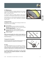
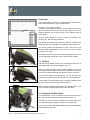
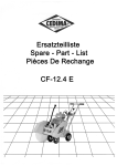
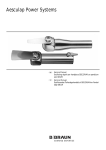
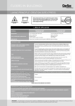
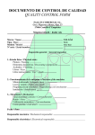
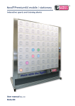
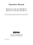
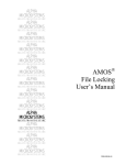
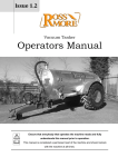
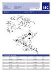
Operating manual
EXTRO-STRIPPER 230 V /50 Hz
English
Item-No.
038588
EXTRO-STRIPPER 115 V /50-60 Hz
Item-No.
039121
Read before use and keep safe
Contents
Technical data . . . . . . . . . . . . . . . . . . . . . . . . . . . . . . . . . . . . . . . . . . . . . . . . . . .Page 9
Safety . . . . . . . . . . . . . . . . . . . . . . . . . . . . . . . . . . . . . . . . . . . . . . . . . . . . . . . . . .Page 9
Safety Instructions . . . . . . . . . . . . . . . . . . . . . . . . . . . . . . . . . . . . . . . . . . . . . . . .Page 9
Maintenance . . . . . . . . . . . . . . . . . . . . . . . . . . . . . . . . . . . . . . . . . . . . . . . . . . . .Page 11
Use . . . . . . . . . . . . . . . . . . . . . . . . . . . . . . . . . . . . . . . . . . . . . . . . . . . . . . . . . . .Page 11
Information about various floorings . . . . . . . . . . . . . . . . . . . . . . . . . . . . . . . . . . . Page 13
Trouble Shooting . . . . . . . . . . . . . . . . . . . . . . . . . . . . . . . . . . . . . . . . . . . . . . . .Page 13
Spare Parts / drawing . . . . . . . . . . . . . . . . . . . . . . . . . . . . . . . . . . . . . . . . . . . .appendix
01/2006
EXTRO-STRIPPER 2, 230 V Artikel. Nr 038588, 115 V Item-No. 039121,RÄSM
8
1.0 Technical Data
Comes with
Power supply . . . . . . . . . . . . . . . . . . . . . . . . . . .230 V / 115 V
Power consumption . . . . . . . . . . . . . . . . . . .2500 W / 2300 W
Number of strokes . . . . . . . . . . . . . . . . . . . .5000 strokes/min
Sound pressure level . . . . . . . . . . . . . . . . . . . . . . . . .92 dB(A)
Sound energy level . . . . . . . . . . . . . . . . . . . . . . . . .105 dB(A)
Hand/Arm-Vibration . . . . . . . . . . . . . . . . . . . . . . . . . .10 m/s2
Weight . . . . . . . . . . . . . . . . . . . . . . . . . . . . . . . . . . . . .122 kg
EXTRO-STRIPPER
Spare blade
Ear protectors
Thread Plug
Tools
Operating manual
Safety gloves
2.0
Declaration of conformity
We declare under our sole responsibility that this product is
in conformity with the following standards of standardization
documents: EN 50 144, according to the provisions of the
Directives 73/23/EWG, 89/336/EWG 98/37 EG
05
Dipl.-Ing. (FH) Dieter Hammel
Konstruktionsleitung
i.V.
WOLFF | Eine Marke der Uzin Utz Gruppe | D-71665 Vaihingen/Enz | Dieselstraße 19
3.0 Safety instructions
Disconnect the power supply before any maintenance is carried
out.
Use only recommended blades and ensure it is sharp before
starting.
Maintenance should be undertaken only by qualified personnel.
Use only genuine Wolff spare parts.
Transport
To avoid harm or danger, always remove the blade before
transporting the machine.
Disconnect the power supply and the plug of the motor before
removing the handle.
Always wear ear protectors!
The user and any person not far off should always use ear
protectors!
See supplementary sheet "General safety instructions"
01/2006
EXTRO-STRIPPER 2, 230 V Artikel. Nr 038588, 115 V Item-No. 039121,RÄSM
9
3.1 Introduction
This operating manual should be used to get the most benefit
from your EXTRO-STRIPPER.
Following these instructions will both extend the life of your
machine and reduce repair costs. Please ensure any user of the
machine is fully familiar with the instructions for use before
allowing work to start.
3.2 Danger while working with the machine
Use this machine only
as instructed in this operating manual
with the machine in perfect working order.
The EXTRO-STRIPPER is designed to the highest technical
standards. Incorrect use can be dangerous!
Disturbances that could impair safety, have to be eliminated at
once.
3.3 Restriction of use
WOLFF cannot be held responsible for any damage or
loss caused by incorrect use Correct use also includes
to take care of all directions from the operating
manual and
the execution of maintenance and service.
The EXTRO-STRIPPER is exclusively for removing bonded
floor coverings in dry environments.
It should not be used for any other purpose. Wolff cannot be
held responsible for any damage or loss caused by incorrect use.
3.4 Genuine Spare Parts
Spare parts and accessories are manufactured uniquely for the
Turbo- Stripper. It must be emphasized that parts obtained from
unauthorized sources must not be used.
Wolff cannot be held responsible for the performance of or any
damage arising from the use of machines in which genuine
spare parts have not been used.
This is particularly important with replacement blades.
01/2006
EXTRO-STRIPPER 2, 230 V Artikel. Nr 038588, 115 V Item-No. 039121,RÄSM
10
4.0 Maintenance
The EXTRO-STRIPPER is virtually maintenance-free. Have the
guides of the swing bolts lubricated from time to time (after
approx. 500 square meters).
Lubricator nipples
The lubricator nipples are located collateral on the front side
(see picture). The used grease will flush dirt out of the machine.
Press maximum 3 to 4 times with the grease gun. Never press
too much grease into the machine. Otherwise the mechanism
will be blocked.
Changing the blade
Disconnect the power supply before changing the blade. Use
work gloves for your own safety.
tip the machine
put on the blade protection (enclosed in the tools set)
Warning! Very sharp blade! You may cause injury without
using the blade protection!
secure the tipped machine from tilting over
clean and loosen the screws of the blade mounting,
Attention! Set the wrench at a position opposite to the
blade to avoid injury.
replace the blade.
2
Make sure that the blade fits in exactly into the support. On
normal and hard subfloors the bevel of the blade should show
upwards (1), on soft subfloors (e.g. chipboards) the bevel should
show downwards (2).
1
Changing the driving wheels
Remove the splint-pins and pull the wheels from the axle. Do not
loose the springs (Pos. 53) under any circumstances!
52
53
32
30
5.0 Use
The EXTRO-STRIPPER removes any bonded floor coverings in
strips. This procedure corresponds with the customary method
of using a hand floor scraper. The stripper works with a thin steel
blade at very high frequency, minimizing vibration and noise.
The EXTRO-STRIPPER is self propelled. The motor actuates
both the blade and the machine movement. The blade drive
starts as soon as the machine is switched on. The hand clutch
will engage the drive.
01/2006
EXTRO-STRIPPER 2, 230 V Artikel. Nr 038588, 115 V Item-No. 039121,RÄSM
11
Preparations
Before starting work, cut the floor covering into strips of about 35 cm.
You cannot work faster if you cut wider strips.
blade`s
width
Messerbreite
1
6 5 4 3 2
To begin, cut one strip crosswise.
Then lift the floor slightly in order to get the blade underneath it.
We recommend to cut the first strip at right angles to the main
working direction. By so doing access to the adjacent strips is
made easier.
Cut the strips smaller if the floor covering is bonded very
securely, e.g. with an epoxy adhesive.
The blades are sharpened by the floor pavement. Therefore the
blade only has to be changed if it is twisted or becomes worn.
(Pic. 1)
The driving wheels are subjected to wear. They have to be
changed after approximately 16 mm (0.6 inch) of the surface
has been worn away.
Otherwise the working angle of the striking apparatus will not be
correct especially critical with cork or foam backed carpets.
5.1 Pull Back
(Pic. 2)
The patented Pull Back system was developed to allow for an
easy pulling back of the Extro Stripper. (Pic. 2)
When you have reached a wall or another obstacle during your
work, simpy pull the handle to lift the driving wheels. The machine
comes to a standstill although the wheels continue to rotate.
If you pull the handle more powerfully, you can pull back the
machine to the place where the next lane is to be stripped off.
If the handle is moved forward again, the driving wheels reach
the floor again and the machine moves forward.
(Pic. 3)
When working, make sure the handle is pressed gently to the
front so that the small transportation rollers are lifted.
5.1.1Locking the Pull Back system
For certain floors, it may be required to lock the Pull Back system. Use the two screws in the lifting brackets. (Pic. 2)
Unscrew the screws, press the handle to the front and tighten
the screws through the lifting brackets to the angled clips.
Screw
01/2006
If you pull the handle, the blade is lifted from the floor immediately
without stopping the drive.
EXTRO-STRIPPER 2, 230 V Artikel. Nr 038588, 115 V Item-No. 039121,RÄSM
12
5.2 Switching on the machine
The EXTRO-STRIPPER is equipped with a power-on indicator
lamp and red lever located at the top of the switch housing. The
switch has a restart protection for low-voltage failures.
If the lamp does not indicate power-on, use another power
socket or check power supply.
The machine is switched on by pulling the red lever. The drive
and the impact system start at the same time.
When the red lever is released, the machine is switched off.
Note the after-running of the machine.
6.0 Information about certain floor coverings
Needlepunch felt and tufted carpets on jute hessian backings
Cut into strips of approx. 35 cm (14 inch) width. If the flooring is
bonded very tight, cut strips smaller. The machine should remove
the flooring without slipping wheels.
Carpets with foam backing
A sharp blade is essential in order to ensure the floor covering is
removed together with the foam backing.
Remove floorings across the width, particularly if you have an
uneven sub-floor.
Tiles
Use blade of the same width as the tiles and use a new blade.
Tiles above size 30 x 30cm (12 x 12inch) have to be cut into half.
If the sub-floor is uneven, use smaller blades.
In all cases, check from time to time to ensure the blade is still
sharp. If it is not or any distortion has occurred, replace it immediately.
7.0 Trouble Shooting
Trouble
Machine does not
run
Eventual cause
Power supply
disconnected
blown fuse
defective cable or plug
Elimination
Have machine
repaired by a qualified
electrician, respective
change parts
Undue force necessary
or excessive vibration
Blade is blunt
Change blade
Excessive vibration
Expendable parts are
worn out
Return machine for
service and/or repair
01/2006
EXTRO-STRIPPER 2, 230 V Artikel. Nr 038588, 115 V Item-No. 039121,RÄSM
13
Ersatzteilliste / Spare parts list / Liste des pièces de rechange
Pos
1
4
5
6
8
12
13
20
21
22
23
25
26
27
28
30
32
33
34
35
36
37
38
39
40
41
42
46
48
49
52
53
54
57
58
61
62
63
64
65
66
67
68
69
70
71
72
73
75
76
77
77
77
78
79
Pcs
1
2
14
20
1
1
2
1
1
9
4
2
6
2
2
2
2
1
4
6
1
1
1
1
1
2
2
2
1
1
1
2
1
2
2
1
1
1
2
2
1
2
2
1
1
1
1
2
4
8
1
1
1
1
1
01/2006
Art.No
015106
016228
014736
014860
014914
038533
014735
038536
015127
014734
014763
015132
014833
014744
015417
014888
015135
021505
014741
014861
021599
032752
032743
032741
032747
032746
014703
014859
015140
014938
015142
014902
015036
033399
014886
014904
015144
014875
014710
014856
014850
014712
014853
015145
014901
014903
014852
017079
014742
014876
015057
015056
019910
015129
014973
Bezeichnung
Rahmenplatte
Führungshülse 4kt
Zylinderschraube M8x30
Schnorrscheibe 8 mm
Schmiernippel
Haube
Zylinderschraube M8x25
Abweiser
Schwingerkopf
Zylinderschraube M8x20
Senkschraube M10x25
Führungshülse
U-Scheibe, 13 mm
Zylinderschraube M12x30
Pleuellager
Klappsplint
Antriebsrad B16, glatt
Getriebehalterung, rechts compl.
Zylinderschraube M10x45
Schnorrscheibe 10 mm
T-Schraube
Gummipuffer Extro
Anhebewinkel rechts Extro
Anhebewinkel links Extro-Str.
Transportachs Extro
Klemmlasche Extro-Str
Kugellager 6004
Schnorrscheibe, 6 mm
Getriebe
Zahnriemen
Antriebsachse
Passfeder 5x5x32
Getriebehalterung, links compl.
Transportrad
Splint 3,2x32
Paßfeder 6x6x32
Pleuel
Pleuelbolzen
Kugellager 6206
Seegerring I62
Seegerring A17
Kugellager 6305
Seegerring A 30
Exzenterwelle
Paßfeder 4x4x20
Paßfeder 6x6x25
Seegerring A25
Lagerbock, re/li
Zylinderschraube M10x70
Zylinderstift 8x40
Motor, 230V
Motor, 115V
Motor, 100V
Zahnscheibe
Zuleitung, kurz, Schuko
WOLFF EXTRO-STRIPPER 2 02/2006
Description
Chassis
Piston block
Screw M 8x30
Washer, 8 mm
Lubricating nippel
Cover
Screw M8x25
Blade holder
Striking foot Turbo
Cyl. screw M8x20
Screw M10x25
Piston rods
Washer, 13 mm
Screw M12x30
Connecting block
Wheel pin
Drive wheel B16
Gear mounting block, right compl.
Screw M10x45
Safety washer, 10 mm
T-Screw short
Rubber stop
Lift bracket right
Lift bracket left
Transport axle
Bracket
Ball bearing 6004
Washer, 6 mm
Gear block
Drive belt
Drive shaft axle
Key 5x5x32
Gear mounting block, left compl.
Nylon wheel
Split-pin 3,2x32
Nut key 6x6x32
Connecting rod
Connecting rod pin
Ball bearing 6206
Circlip I62
Circlip A17
Ball bearing 6305
Circlip A 30
Excenter shaft Turbo
Nut key 4x4x20
Key 6x6x25
Circlip A 25
Bearing block, right/left
Screw M10x70
Cyl. pin 8x40
Motor, 230V
Motor, 115V
Motor, 100V
Drive sprocket
Electrical cord with plug
EXTRO-STRIPPER 2, 230 V Artikel. Nr 038588, 115 V Item-No. 039121,RÄSM
Dénomination
Plaque à cadre
Douille de guidage, carrée
Vis à tête cylindrique M8x30
Disque Schnorr 8 mm
Graisseur
Capot
Vis à tête cylindrique M8x25
Déflecteur
Tête porte-lame oscillante
Vis à tête cylindrique M8x20
Vis à tête conique M10x25
Douille de guidage
Rondelle, 13 mm
Vis à tête cylindrique M12x30
Coussinet de bielle
Goupille fendue à charnière
Roue d'entraînement B 16, lisse
Porte-engrenage à droite compl.
Vis à tête cylindrique M10x45
Disque Schnorr 10 mm
Vis T, court
Manchette en caoutchouc
coin à droite
coin à gauche
Arbre de transport
Couvre-joint
Roulement à billes 6004
Disque Schnorr, 6 mm
Engrenage
Courroie dentée
Arbre de transmission
Ressort d'ajustage 5x5x32
Porte-engrenage à gauche compl.
Roue de transport
Goupille 3,2x32
Ressort d'ajustage 6x6x32
Bielle
Boulon de bielle
Roulement à billes 6206
Anneau Truarc I62
Anneau Truarc A17
Roulement à billes 6305
Anneau Truarc A 30
Arbre excentrique
Ressort d'ajustage 4x4x20
Ressort d'ajustage 6x6x25
Anneau Truarc A 25
Palier à droite/ gauche
Vis à tête cylindrique M 10x70
Goupille cylindrique 8x40
Moteur, 230V
Moteur, 115V
Moteur, 100V
Disque denté
Alimentation, courte, contact sécurité
20
Pos
80
81
82
84
85
86
87
88
89
90
91
92
94
95
96
97
98
99
100
101
102
103
104
105
106
107
108
109
110
113
115
117
118
119
121
122
123
125
126
127
128
129
130
130
133
137
139
140
141
142
146
146
147
148
149
150
151
Pcs
1
4
4
1
1
1
1
1
1
2
2
2
1
1
5
1
1
1
4
1
2
1
2
1
1
1
1
2
1
1
1
1
4
1
4
2
1
2
1
2
1
1
1
1
2
2
2
2
1
1
1
1
1
2
2
1
1
01/2006
Art.No
016860
014721
014858
014937
038531
038508
038509
014974
038567
037953
018800
014735
015154
039202
014799
014970
015155
015156
014828
014845
018153
038606
014862
015164
038633
038506
038505
038566
039234
015130
014724
014910
014835
014984
118141
014737
039188
018284
032751
014992
015125
017559
013978
013979
015107
017452
018259
038585
014816
014848
017439
021237
020969
038284
038568
017473
038584
Bezeichnung
Motorwinkel universal
Zylinderschraube M5x25
Schnorrscheibe 5 mm
Zahnriemen
SG-Stielhalterung
Aussenrohr
Innenrohr
Zuleitung m Kupplung
Klemmhebel M10x16
Arretierbolzen
Stopfen
Zylinderschraube DIN 912 M8x25
Abdeckung
Griffrohr
Linsenflansch-Kopfschraube
Zuleitung, lang
Zahnriemenscheibe Z 24
Zahnriemenscheibe Z 12
U-Scheibe Ø 8,4
Kompaktnutring
Sechskantschraube DIN 933 M8x22
Halter für Bügel
Schnorrscheibe 12 mm
Anlaufscheibe
Bügel
Schaltergehäuse
Deckel
Klemmhebel M10x50
Dreisternschraube M10x80
Motordeckel, neu
Zylinderschraube M5x90
Buchse 20x26x30
Scheibe
Signalleuchte 230V
Etikett
Zylinderschraube M8x35/912
Kabelkanal
Zylinderschraube M4x12/912
Totmanngriff
Verschraubung PG 11
Fuß-Stütze
Zugentlastung
Ersatzmesser 1,0
Ersatzmesser 1,5
Lasche
U-Scheibe Ø 4,3
Zylinderschraube 912/M6x60
Verschr. m. Biegeschutz M16x1,5
Stopmutter DIN 985 M8
Zahnscheibe DIN 6797-A4.3
Schütz 115V
Schütz 230V
Hutschiene
Zylinderschraube M6x105
Griffbezug
Messingschraube 84/M4x8
Verschr. m. Biegeschutz M12x1,5
Description
Motor plate, new
Screw M 5x25
Washer, 5 mm
Drive belt
Handle bracket
Outer tube
Inner tube
Electrical cord
Clamping lever
Arresting bolt
Stopper
Cylindrical screw
Cover
Handle complete
Screw
Electrical cord, long
Belt pulley Z 24
Belt pulley Z 12
Washer Ø 8,4
Groove ring
Hexagon bolt
Bracket
Washer, 12 mm
Starter disc
Rod
Switch housing
Cover
Clamping lever
Screw
Motor cover, new
Screw M 5x90
Bush 20x26x30
Washer
Indicator 230V
Etikett
Cyl. screw M8x35
Cable pit
Cyl. screw M4x12/912
Dead man grip
Protective cut-out switch
Tilt support
Strain relief
Replacement blade 1,0
Replacement blade 1,5
Bracket
Washer Ø 4,3
Cylincrical screw
Fitting
Stop nut
Washer
Contactor 115V
Contactor 230V
Top hat rail
Cylincrical screw
Grip covering
Screw 84/M4x8
Fitting
EXTRO-STRIPPER 2, 230 V Artikel. Nr 038588, 115 V Item-No. 039121,RÄSM
Dénomination
Equerre moteur
Vis à tête cylindrique M5x25
Disque Schnorr, 5 mm
Courroie dentée
Porte-manche
Tube extérieur
Tube intérieur
Alimentation, courte,
Levier de serrage
Axe d'arrêttage
Bouchon
Vis à tête cylindrique
Recouvrement
Tube d` poignée
Bride bombée, vis à tête goutte-de-suif
Alimentation, longue
Disque de courroie dentée Z 24
Disque de courroie dentée Z 12
Rondelle Ø 8,4
Joint en U à lèvres
Vis à tête hexagonale
Fixation
Disque Schnorr 12 mm
Disque de démarrage
Etrier
Couvercle de levier
Couvercle
Levier de serrage
Vis Spax
Couvercle de moteur
Vis à tête cylindrique M5x90
Douille 20x26x30
Disque
Indicateur 230V
Etiquette
Vis à tête cylindrique M8x35
Conduite de câbles
Vis à tête cylindrique M4x12/912
Homme mort prise
Disjoncteur de protection
Manche de sécurité
Décharge de traction
Lame de rechange 1,0
Lame de rechange 1,5
Couvre-joint
Disque Ø 4,3
Vis cylindrique
Fermeture
Ecrou d´arrêt
Rondelle
Contacteur 115V
Contacteur 230V
Barre
Vis cylindrique
Coussinets pour poignée
Vis 84/M4x8
Fermeture
21
Pos
153
154
155
156
158
157
Pcs
2
1
2
1
1
1
Art.No
038581
014696
018280
039636
021232
014844
Bezeichnung
Schalter f. Totmanngriff
Sanftanlauf
Zylinderschraube 912/M4x8
Abkippstütze
Flanschkopfschraube
Federring
Description
Switch
Current limitor
Cylincrical screw
Column
Counter sink screw
Split washer
Zubehör / accessories / accessoires Extro Stripper
1
1
38590
Anleitung Extro 3-sprachig
2
2
015161 Tragegriff m.Kette
3
1
015162 Werkzeugsatz TURBO
4
1
015315 Gehörschützer
5
1
015809 Schutzhandschuhe, 1 Paar
6
1
017661 Kontrollnachweis
7
1
107287 Einlage Systemstiel
8
1
107291 Holzkiste
9
1
107299 Karton Systemstiel
11 1
Messerschutz
Dénomination
Interrupteur
Limiteur de courant
Vis cylindrique
Pilier
Vis à tête conique
Rondelle éalstique bombée
Operating manual
Grip with chain
Tool kit
Ear protector
gloves
Certificate
Stiffening handle
Wooden box
Board handle
Thread Plug
Mode d‘emploi
Poignée de manutention avec chaîne
Jeu d'outils
protection de l’ouïe
gants
Preuve
Apport manche
Caisse en bois
carton manche
Bouchon filetée
108
Explosion Stiel
EXTRO-Stripper
20.01.06
121
146
155
155
154
137
150
141
147
142
107
100
125
149
126
140
119
151
129
139
102
100
123
153
140
86
148
6
92
91
87
157
90
122
95
149
158
156
89
90
97
88
01/2006
EXTRO-STRIPPER 2, 230 V Artikel. Nr 038588, 115 V Item-No. 039121,RÄSM
22
M
braun
braun
Schaltplan
EXTRO-Stripper
230 V
24.01.2006
Motor Pos:77
T3
A2
A2
Signalleuchte Pos:116
schwarz
Schütz Pos:146
schwarz
Sanftanlauf Pos:154
T2
L3
A1
T1
L2
L1
L
N
PE
Gehäuse Pos:107
Schalter Pos:153
T3
A2
A2
A1
Motor Pos:77
T2
L3
Signalleuchte Pos:116
Schaltplan
EXTRO-Stripper
100/115 V
24.01.2006
Schütz Pos:146
M
T1
L2
L1
L
N
PE
Schalter Pos:153
01/2006
EXTRO-STRIPPER 2, 230 V Artikel. Nr 038588, 115 V Item-No. 039121,RÄSM
Gehäuse Pos:107
23
32
49
75
35
73
130 22
23
66
99
46
35
96
34
EXTRO-Stripper
Art. Nr. 038588
24.01.2006
20
30
42
25
80
76
26
81
67
27
21
104
82
105
33
117
28
5
6
1
76
78
22
6
63
84
77
115
79
113
92
103
92
28
92
94
68
96
118
4
8
62
133
22
41
64
106
92
64
22
41
65
70
48
76
73
35
75
69
57
22
67
61 101
52
71
68
53
38
39
37
58 26
110
53
34
12
46
96
117
42
98 72
54
90 22
32
85 6
30
57
22
26
40
58
6
109
22
128
WOLFF | Eine Marke der Uzin Utz Gruppe
WOLFF | Eine Marke der Uzin Utz Gruppe | D-71665 Vaihingen/Enz | Dieselstraße 19 | Tel. +49 (0)70 42 95 11- 0 | Fax +49 (0)70 42 95 11- 44 | E-Mail [email protected] | Internet www.uzin-utz.com 24