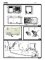
1
mase GENERATORS I.S. 29 60 Hz I - MANUALE D' INSTALLAZIONE GB - INSTALLATION MANUAL F - MANUEL DINSTALLATION D - INSTALLATIOSHANDBUCH E - MANUAL DE INSTALACION NL - INSTALLATIEHANDLEIDING Rev.0 MC. 24/07/02 Cod. 42230 IS 29 GENERATORS 830 1460 718 88 202 640 88 Ø13 17.5 364 17.5 675 Fig. 1 1 Fig. 2 2 Fig. 3 Fig. 4 -2- IS 29 GENERATORS Fig. 5 Fig. 6 Fig. 7 Valvola antisifone Anti-siphon valve Soupape antisiphon Beluchter 1 Fig. 8 Fig. 9 -3- IS 29 GENERATORS 1 4 1 Fig.12 -4- 3 2 Fig.10 IS 29 GENERATORS 1 Fig.14 RETE MAINS RESEAU WALAANSL GEN. CARICO LOAD CHARGE VERBRUIKERS Fig.15 -5- IS 29 GENERATORS WIRING DIAGRAM / SCHEMA ELETTRICO cod.45476 Fig.16 -6- GENERATORS I INDICE Figure .................................................................................................................................... 2 Schema elettrico .................................................................................................................. 6 1 1.1 1.2 INFORMAZIONI GENERALI ......................................................................................... 8 Scopo e campo di applicazione del manuale ................................................................. 8 Simbologia .................................................................................................................... 8 2 Prescrizioni per la sicurezza durante l'installazione e la messa in servizio ........ 9 3 3.1 3.2 3.3 INSTALLAZIONE Caratteristiche del vano ................................................................................................. 9 Ancoraggio del gruppo .................................................................................................. 9 Ventilazione .................................................................................................................. 9 4 4.1 4.2.1 4.2.2 4.3 4.4 CIRCUITO ACQUA DI RAFFREDDAMENTO ................................................................ 9 Sistemi di adduzione dell'acqua di mare ........................................................................ 9 Tipica installazione con gruppo elettrogeno sopra la linea di galleggiamento ................. 9 Tipica installazione con gruppo elettrogeno sotto la linea di galleggiamento ................ 10 Componenti ................................................................................................................. 10 Sistema di scarico ...................................................................................................... 10 5 CIRCUITO COMBUSTIBILE ....................................................................................... 11 6 6.1 6.2 6.3 6.4 COLLEGAMENTI ELETTRICI ..................................................................................... 11 Allacciamento batteria ................................................................................................ 11 Allacciamento pannello di comando remoto ................................................................ 11 Allacciamento c.a. ...................................................................................................... 11 Commutazione generatore - rete ................................................................................. 12 7 MOVIMENTAZIONE .................................................................................................... 12 8 RIFERIMENTI SCHEMA ELETTRICO ......................................................................... 12 -7- IS 29 I GENERATORS IS 29 1 INFORMAZIONI GENERALI Consultare attentamente questo manuale prima di procedere a qualsiasi intervento sulla macchina. IL MANCATO RISPETTO DELLE SPECIFICHE CONTENUTE NEL SEGUENTE MANUALE DI USO E MANUTEZIONE COMPORTA IL DECADIMENTO DELLA GARANZIA SUL PRODOTTO 1.1 Scopo e campo di applicazione del manuale Grazie per aver scelto un prodotto mase. Questo manuale è stato redatto dal Costruttore allo scopo di fornire le informazioni e le istruzioni essenziali per effettuare, correttamente e in condizioni di sicurezza l'installazione, e costituisce parte integrante del corredo del gruppo elettrogeno e deve essere conservato con cura da qualsiasi agente che potrebbe deteriorarlo per tutto il ciclo di vita dello stesso. Il presente manuale deve seguire il gruppo elettrogeno qualora questo sia trasferito ad un nuovo utente o proprietario. Le informazioni in esso contenute sono dirette a tutte le persone coinvolte nel ciclo di vita operativo del gruppo elettrogeno e sono necessarie per informare sia chi materialmente effettuerà le diverse attività, sia chi dovrà coordinarle, predisporre la necessaria logistica e regolamentare gli accessi al luogo dove sarà installato ed opererà il gruppo elettrogeno. Il manuale definisce lo scopo per cui la macchina è stata costruita e contiene tutte le informazioni necessarie per garantirne un uso sicuro e corretto. La costante osservanza delle indicazioni, in esso contenute, garantisce la sicurezza delloperatore, leconomia desercizio ed una maggiore durata della macchina stessa. Si consiglia vivamente di leggere attentamente quanto contenuto in questo manuale e nei documenti di riferimento; solo così viene assicurato il regolare funzionamento nel tempo del gruppo elettrogeno, la sua affidabilità e la salvaguardia da danni a persone e cose. I disegni sono forniti a scopo esemplificativo. Anche se la macchina in vostro possesso si differenzia sensibilmente dalle illustrazioni contenute in questo manuale la sicurezza e le informazioni sulla stessa sono garantite. Per facilitare la consultazione esso è stato suddiviso in sezioni che ne identificano i concetti principali; per una consultazione rapida degli argomenti consultare lindice descrittivo. Nota: le informazioni contenute in questa pubblicazione sono corrette al momento della stampa. Il Costruttore, nel perseguire una politica di costante sviluppo ed aggiornamento del prodotto, si riserva di apportare modifiche senza preavviso. 1.2 Simbologia Le parti di testo da non trascurare sono state evidenziate in grassetto e precedute da simboli qui di seguito illustrati e definiti. Indica che è necessario prestare attenzione al fine di non incorrere in serie conseguenze che potrebbero provocare la morte, o possibili danni alla salute, del personale. Situazione che potrebbe verificarsi durante il periodo di vita di un prodotto, sistema o impianto considerato a rischio in materia di danni alle persone, alle proprietà, allambiente o di perdite economiche. Indica che è necessario prestare attenzione al fine di non incorrere in serie conseguenze che potrebbero portare al danneggiamento di beni materiali quali le risorse o il prodotto Indicazioni di particolare importanza. -8- I GENERATORS 2 PRESCRIZIONI PER LA SICUREZZA DURANTE L'INSTALLAZIONE E LA MESSA IN SERVIZIO 4 CIRCUITO ACQUA DI RAFFREDDAMENTO Il motore del gruppo elettrogeno viene raffreddato da un sistema a circuito chiuso con scambiatore di calore. All'atto dell'installazione è necessario predisporre un circuito di adduzione dell'acqua di mare per il raffreddamento e un sistema di scarico per la miscela di gas di combustione ed acqua. - Il personale incaricato all'installazione o messa in opera del gruppo elettrogeno dovrà sempre usare casco protettivo; indossare scarpe antinfortunistiche e la tuta. - Usare guanti antinfortunistici. - Non lasciare parti smontate, attrezzi o quant'altro non facente parte dell'impianto sul motore o nelle vicinanze. - Non lasciare mai liquidi infiammabili o stracci imbevuti di liquido infiammabile in prossimità del gruppo elettrogeno, vicino ad apparecchiature elettriche (incluse lampade) o parti d'impianto elettrico. - Prendere precauzioni per evitare il pericolo di folgorazioni. 4.1 1 - Sistema a presa diretta 2 - Sistema con deflettore La MASE raccomanda il sistema a presa diretta (fig.3, rif.1) in quanto questo sistema previene l'ingresso di acqua in pressione nei condotti di aspirazione, generando invece una depressione facilmente superabile dalla prevalenza della pompa acqua del gruppo elettrogeno. Caratteristiche del vano Non applicare nessun tipo di Il generatore deve essere installato in un locale sufficientemente aerato, in grado di assicurare la poca quantità d'aria necessaria alla combustione del motore. Il locale deve essere separato ed isolato acusticamente dalle aree abitabili. Il generatore va posizionato in modo da facilitare le normali operazioni di manutenzione. E' consigliabile l'installazione nel locale dei motori di propulsione a patto che questo sia conforme alle condizioni sopracitate. 3.2 cuffia di protezione al sistema a presa diretta. Il sistema con deflettore può invece causare i seguenti inconvenienti: a - Se viene montato con le asole rivolte verso la prua. In questo caso durante la navigazione e con gruppo elettrogeno spento si crea una pressione nel condotto immissione acqua, che può causare il riempimento dell'impianto, fino al raggiungimento delle luci di scarico rendendo così possibile l'ingresso di acqua nei cilindri. b - Se viene montato con le asole rivolte verso la poppa. In questo caso durante la navigazione si può creare una depressione nel condotto immissione acqua, tale da impedire alla pompa acqua di innescare l'impianto di raffreddamento o tale da limitare la portata con conseguente surriscaldamento del gruppo elettrogeno. Ancoraggio del gruppo Per il fissaggio del gruppo, predisporre un basamento per sopportare peso e vibrazioni. Procedere alla foratura del basamento seguendo le indicazioni di fig.1. 3.3 Sistema di adduzione dell'acqua di mare Sulle imbarcazioni i sistemi normalmente adottati per l'immissione dell'acqua sono due (fig. 3). 3 INSTALLAZIONE 3.1 IS 29 Ventilazione 4.2.1 Tipica installazione con gruppo elettrogeno sopra la linea di galleggiamento (fig.4) Il generatore è dotato di un sistema interno di raffreddamento forzato attraverso uno scambiatore acqua/aria. 1 2 3 4 5 6 7 La quantità di aria necessaria alla combustione viene aspirata tramite l'apertura posta sul basamento (fig. 2): assicurarsi quindi che questa apertura sia sempre ben libera. Scarico a mare Silenziatore Marmitta Filtro acqua Rubinetto generale impianto Presa a mare Rubinetto di svuotamento A - Tubazione diametro interno Ø75 mm. B - Tubazione diametro interno Ø25 mm. C - Tubazione diametro interno Ø16 mm. -9- I GENERATORS IS 29 Portata acqua IS 21.5-23.5: 40-45 L/min. 4.2.2 Tipica installazione con gruppo elettrogeno sotto la linea di galleggiamento (fig.5) 1 2 3 4 5 6 7 8 9 A B C D Scarico a mare Silenziatore Marmitta Filtro acqua Rubinetto generale impianto Presa a mare Rubinetto di svuotamento Valvola antisifone Drenaggio - Tubazione diametro interno - Tubazione diametro interno - Tubazione diametro interno - Tubazione diametro interno tipo fine. Si consiglia il tipo con passo 2 - 470 micron, misure diverse non consentirebbero un buon rendimento del filtro. 5 - Valvola antisifone: è una valvola che riporta a pressione atmosferica il circuito di raffreddamento a motore spento, evitando il fenomeno di sifonaggio. Va obbligatoriamente usata quando la base del gruppo elettrogeno si trova sotto la linea di galleggiamento, e va posizionato ad almeno 50 cm sopra il livello del mare. (vedi fig.5). Ø75 mm. Ø25 mm. Ø16 mm. Ø14 mm. La valvola antisifone va inserita - E' molto importante rispettare le misure riportate negli gli schemi d'installazione - Le marmitte (rif.3 di fig.4 e 5 ) hanno il compito di raccogliere l'acqua presente nelle tubazioni di scarico quando viene spento il motore del gruppo elettrogeno ed impedire che questa defluisca all'interno del motore attraverso il collettore e la valvola di scarico. Per tale motivo è indispensabile rispettare la posizione della marmitta e la lunghezza delle tubazioni come indicato sullo schema d'installazione. 4.3 La rete filtrante dovrà essere del Componenti tra la mandata della pompa acqua di mare e il miscelatore come indicato alla fig.9. Il condotto di drenaggio della valvola antisifone deve obbligatoriamente viaggiare al di sotto della stessa impedendo così accumuli di acqua nel condotto, che deve rimanere sempre vuoto, per permettere il passaggio di aria nello stesso al momento dello spegnimento del gruppo (vedi fig.7). Si consiglia di portare il condotto di drenaggio della valvola antisifone in sentina, perché dallo stesso, durante il normale funzionamento, potrebbero fuoriuscire piccole quantità di acqua. Il circuito di raffreddamento va collegato al raccordo dello scambiatore come indicato dalla figura 8. 4.4 Il sistema di presa acqua di mare Sistema di scarico Il sistema di scarico gas di combustione/acqua del generatore deve essere indipendente da quello dei motori principali. deve essere indipendente da quello dei motori di propulsione della barca 1 - Presa a mare del tipo diretto 1/2". La lunghezza del tubo dal Nel caso il gruppo venga installato punto più alto del condotto di scarico alla marmitta non deve superare mt. 2. Questo per evitare che allo spegnimento del gruppo l'acqua rimasta nel condotto di scarico possa rifluire al motore dopo aver riempito la marmitta a barilotto. 1 - Marmitta. Attenua la rumorosità dello scarico ed impedisce il riflusso dell'acqua verso il motore. Si consiglia di installare la marmitta a non più di 1 mt. dal generatore e di posizionarla ad una altezza come da fig.4,5,6,7,8,9. ad un altezza superiore ad 1 mt. sopra la linea di galleggiamento, è necessario montare una valvola di non ritorno dopo la presa a mare (fig.6, rif.1) che impedisce lo svuotamento del circuito acqua a motore spento. In caso di svuotamento, durante l'avviamento si può danneggiare la girante della pompa acqua; per lo stesso motivo all'atto del primo avviamento del gruppo, è necessario provvedere al riempimento manuale del tubo di aspirazione dalla valvola alla pompa. 2 - Rubinetto a sfera (Generale impianto) 1/2". 3 - Rubinetto a sfera (Spurgo impianto) 1/2". Serve a vuotare l'impianto di raffreddamento del gruppo elettrogeno per manutenzioni generali o per periodi di lunga inattività. 4 - Filtro acqua (ispezionabile). Deve proteggere efficacemente il circuito di raffreddamento dall'ingresso di fango, sabbia e alghe. 2 - Silenziatore. Riduce ulteriormente la rumorosità. Si consiglia di installarlo ad una distanza non superiore ad 1 mt. dal bocchettone di scarico a mare. 3 - Bocchettone di scarico a mare. Va installato in posizione tale da essere sempre sopra il livello del mare in tutte le condizioni di utilizzo dell'imbarcazione. - 10 - I GENERATORS 5 CIRCUITO COMBUSTIBILE L'alimentazione del gruppo è a gasolio, ed avviene tramite i raccordi contrassegnati dalle diciture "fuel inlet" (fig. 10 rif.2) e "fuel outlet" (fig.10 rif.3); quest'ultimo serve per il ritorno del combustibile in eccesso. Nel collegamento al serbatoio combustibile non sono necessari elementi filtranti, in quanto è già presente sul gruppo un filtro combustibile; è invece buona norma inserire un rubinetto sulla linea di alimentazione a valle del serbatoio, ed una valvola unidirezionale (di non ritorno) onde evitare lo svuotamento dell'impianto combustibile per qualsiasi causa. Utilizzare una valvola con apertura 50 millibar (Prevalenza max 0.8 M). I tubi del combustibile devono essere in gomma resistente agli idrocarburi, di diametro interno 8 mm. Per ulteriori informazioni, attenersi al libretto uso e manutenzione del costruttore del motore. 6 COLLEGAMENTI ELETTRICI 6.1 Allacciamento batteria Per l'avviamento del gruppo è necessario utilizzare una batteria indipendente a 12V, di capacità 100 Ah. La batteria non dovrà essere IS 29 Al fine di minimizzare le correnti galvaniche il (-) della batteria del gruppo elettrogeno non deve essere collegato al (-) delle altre batterie di bordo. 6.2 Collegamento pannello comando a distanza Sono disponibili due modelli di pannello comando remoto, installabili in plancia, che possono essere collegati al gruppo elettrogeno per eseguire lavviamento e larresto. Entrambi i modelli sono forniti con cavo elettrico di collegamento lungo 20 mt. predisposto con connettore di collegamento alle estremità Fissare il connettore del cavo di collegamento nellapposito innesto posto sulla parte inferiore della scatola cruscotto interna al gruppo elettrogeno (fig.14 rif.1) e la parte opposta al pannello di comando remoto. 6.3 Allacciamento c.a. Il collegamento è da effettuare allacciandosi direttamente sull'interruttore magnetotermico (Fig.13 Rif.1). Si accede all'interruttore magnetotermico rimuovendo i pannelli frontali della macchina Il collegamento di questo gruppo elettrogeno al magnetotermico prevede la possibilità di prelevare solo tensione monofase 120V 60Hz. - Assicurarsi che la somma dei carichi da alimentare non superi la potenza nominale del gruppo elettrogeno. inferiore alla capacità indicata. Essa va allacciata ai morsetti del generatore (fig.10 rif.4) con cavi di sez. 25 mm2 fino a distanze di 5 mt., con cavi di sez. 35 mm2 per distanze maggiori, rispettando questa sequenza di operazioni: - Collegare prima il polo positivo (+) della batteria al terminale contrassegnato dal simbolo (+) sul generatore. - Collegare successivamente il polo negativo (-) della batteria al terminale contrassegnato dal simbolo (-) sul generatore. - Cospargere le connessioni con specifico grasso minerale, al fine di ridurre ossidazioni o corrosioni. Il generatore è dotato di un dispositivo elettronico per la ricarica automatica della batteria di avviamento, capace di erogare 40 A, ad una tensione di 12V, a pieno carico. Installare la batteria in un vano aerato, separato dal generatore e da ogni dispositivo che possa provocare calore o scintille. Verificare periodicamente lo stato delle connessioni dei morsetti ed il livello acqua batteria. Nel caso si renda necessario scollegare i cavi, agire inversamente all'ordine raccomandato nel collegarli. Non invertire le polarità dei cavi di connessione; il generatore e la batteria potrebbero esserne seriamente danneggiati. Non collegare altri carichi alla batteria. - 11 - - Il gruppo elettrogeno è dotato di una protezione magnetotermica che interrompe l'erogazione di corrente in caso di sovraccarico o cortocircuito. Tabella caratteristiche per uscita singola IS 29 +] 9 60 240 120 .Z $ 22.4 93,3 186,6 I GENERATORS 6.4 Commutazione generatore - rete E' necessario interporre sulla linea di utilizzo un commutatore che permetta di commutare le utenze dal generatore ad una linea di alimentazione esterna. Il commutatore va dimensionato in base all'entità dei carichi in gioco; uno schema di massima è rappresentato in fig.15. 7 MOVIMENTAZIONE Per la movimentazione del gruppo elettrogeno ed il suo sollevamento utilizzare solo gli appositi ganci di sollevamento posti sul motore. Per problemi di bilanciatura, utilizzare contemporaneamente i ganci e mai singolarmente. Agganciare il gruppo elettrogeno in punti diversi da quelli indicati potrebbe causare danni al gruppo stesso o diventare pericoloso per gli operatori 8 RIFERIMENTI SCHEMA ELETTRICO Vedere fig.16 1 - Interruttore magnetotermico 2 - Contaore 3 - Alternatore 4 - Rotore 5 - Statore 6 - Regolatore di tensione 7 - Morsettiera di potenza 8 -/ 9 - Interruttore termico 10 - Pulsante START / STOP 11 - Modulo protezione motore 12 - Morsettiera 13 - Connettore per collegamento pannello a distanza 14 - Indicatore livello carburante 15 - Indicatore di pressione olio 16 - Indicatore di temperatura acqua 17 - Sensore alta temperatura acqua 18 - Sensore alta temperatura liquido refrigerante 19 - Pressostato olio 20 - Alternatore carica batteria 21 - Elettromagnete stop 22 - Motorino d'avviamento 23 - Morsetti di collegamento batteria 24 - Cavo di collegamento pannello 25 - Pulsante START / STOP 26 - Strumento indicatore pressione olio 27 - Strumento indicatore temperatura liquido refrigerante 28 - Kit pannello comando a distanza con strumenti 29 - Kit pannello comando a distanza - 12 - IS 29 GENERATORS I GB IS 29 INDEX Pictures ................................................................................................................................... 2 Wiring diagram ...................................................................................................................... 6 1 1.1 1.2 GENERAL INFORMATION .............................................................................................. 14 Purpose and field of application of the manual ................................................................. 14 Symbols .......................................................................................................................... 14 2 Prescriptions for safety during installation and setup ............................................... 15 3 3.1 3.2 3.3 INSTALLATION .............................................................................................................. 15 Characteristics of the installation space .......................................................................... 15 Fastening the unit to the ground ...................................................................................... 15 Ventilation ....................................................................................................................... 15 4 4.1 4.2.1 4.2.2 4.3 4.4 COOLING WATER CIRCUIT ........................................................................................... 15 Sea water feed system .................................................................................................... 15 Typical installation with generator above the waterline ...................................................... 15 Typical installation with generator below the waterline ...................................................... 16 Components .................................................................................................................... 16 Drainage system.............................................................................................................. 16 5 FUEL CIRCUIT ................................................................................................................ 17 6 6.1 6.2 6.3 6.4 ELECTRICAL CONNECTION .......................................................................................... 17 Battery connection ........................................................................................................... 17 Control panel connection ................................................................................................. 17 A.C. Connection .............................................................................................................. 17 Generator - Mains Switching ............................................................................................ 18 7 HANDLING ...................................................................................................................... 18 8 WIRING DIAGRAM REFERENCES ................................................................................. 18 - 13 - GB GENERATORS IS 29 1 GENERAL INFORMATION Carefully consult this manual before proceeding with any operation on the generator. FAILURE TO RESPECT THE SPECIFICATIONS CONTAINED IN THIS USE AND MAINTENANCE MANUAL WILL RESULT IN FORFEITURE OF THE GUARANTEE ON THE PRODUCT 1.1 Purpose and field of application of the manual Thank you for choosing a mase product. This manual has been drawn up by the manufacturer with the purpose of providing essential information and instructions for proper installation in conditions of safety and constitutes an integral part of the generator equipment. The manual must be kept safely, protected from any agent which might damage it, for the entire life of the generator and must accompany the generator if transferred to another user or owner. The information contained in the manual is addressed to all those persons involved in the operating life cycle of the generator, and is necessary to inform both those who effectively carry out the different operations and those who coordinate the activities, arrange the necessary logistics and regulate access to the place where the generator will be installed and operated. The manual defines the purpose for which the generator was constructed and contains all the information necessary to guarantee safe and proper use. Constant observance of the instructions contained in this manual guarantees the safety of the operator, operating economy and a longer life of the generator. It is warmly recommended to carefully read the contents of this manual and the reference documents; only thus can regular functioning and reliability of the generator be guaranteed over time, and protection against damage to persons or things. The drawings are provided by way of example. Even if the generator in your possession differs considerably from the illustrations contained in this manual, the safety of the generator and the information provided are nevertheless guaranteed. To facilitate consultation, it has been divided into sections identifying the main concepts; for a quick look at the topics, consult the index. Note: the information contained in this publication is correct at the time of printing. The manufacturer in his pursuit of a policy of constant development and upgrading of the product reserves the right to make modifications without prior notice. 1.2 Symbols Those parts of the text not to be ignored are highlighted in bold type preceded by a symbol, as illustrated and defined below. Indicates that particular attention must be paid in order to prevent running into serious danger which could lead to death or possible hazards to the health of personnel. A condition which may occur during the lifetime of a product, system or plant considered at risk regarding damage to persons, property, the environment or economic loss. Indicates that particular attention must be paid in order to prevent serious consequences which could result in damage to tangible goods, such as the resources or the product. Instructions of particular importance. - 14 - GB GENERATORS 2 Prescriptions for safety during installation and setup - The personnel in charge of installation and starting of the generator must always wear a protective helmet, safety shoes and overalls. - Use protective gloves. - Do not leave disassembled parts, tools or anything else not forming part of the system on or near the engine. - Never leave inflammable liquids or cloths soaked in inflammable liquids in proximity of the generator, near electric equipment (including lamps) or parts of the electrical system. - Take the necessary precautions to prevent the danger of electrocution. - Check that the earthing system has been installed and constructed in accordance with regulations. IS 29 4 COOLING WATER CIRCUIT The engine is cooled by an closed circuit system heat exchanger. On installation a sea water feed circuit should be fitted for cooling and a waste system to expel the mixture of flue gas and water. 4.1 Sea water feed system Boats usually use one of two systems to collect water (fig. 3): 1 - Direct infeed system 2 - System with baffle MASE recommends the direct infeed system (ref.1 fig. 3) since this system prevents water under pressure entering the suction ducts and instead forms a pressure which can easily be overcome by the water pump of the electric generator. Do not apply any type of protective 3 INSTALLATION 3.1 hood to the direct infeed system. Characteristics of the installation space The baffle system might cause the following problems: The generator must be installed in a sufficiently aired space, supplying a little amount of air necessary for the combustion of the motor. The space must be separate and acoustically insulated from living areas. The generator should be positioned so that normal maintenance operations can easily be carried out. Propulsion motors are recommended for installation in the area as long as they comply with the above-mentioned conditions. a - If it is installed with the slots facing the prow. In this case, during navigation and with the electric generator off, pressure is accumulated in the water infeed duct which might cause the system to fill up, even as far as the exhaust port, allowing water to enter the cylinders. 3.2 Fastening the unit to the ground To fasten the unit securely, a base should be installed to absorb vibrations and support the weight. Drill holes in the base according to the instructions in fig.1. 3.3 Ventilation The generator is equipped with an internal forced cooling system through a water/air exchanger. The air needed for combustion is taken in through the opening on the base (fig.2) so care must be taken to ensure that this opening is always free. - 15 - b - If it is installed with the slots facing the stern. In this case a depression might accumulate in the water infeed duct during navigation, preventing the water pump from starting up the cooling plant, or limiting the capacity and subsequently causing the electric generator to overheat. 4.2.1 Typical installation with generator above the waterline (Fig.4) 1 2 3 4 5 6 7 Sea exhaust Silencer Muffler Water filter Main system tap Sea intake Drain tap A - Pipes - inner diameter Ø75 mm. B - Pipes - inner diameter Ø25 mm. C - Pipes - inner diameter Ø16 mm. GB GENERATORS 4.2.2 Typical installation with generator below the water line (Fig.5) 1 2 3 4 5 6 7 8 9 A B C D Sea exhaust Silencer Muffler Water filter Main system tap Sea intake Drain tap Antisiphon valve Drainage - Pipes - inner diameter - Pipes - inner diameter - Pipes - inner diameter - Pipes - inner diameter IS 29 The filter mesh should be very fine. Mesh 2 - 470 micron is recommended, other sizes do not give good filter performance. 5 - Anti-siphon valve: this is a valve that brings the cooling circuit back to atmospheric pressure when the motor is turned off, thus avoiding the formation of siphons. Its use obligatory when the base of the generator group is under the water line, and it must be positioned at least 50 cm. above sea level. (see fig.5). Ø75 mm. Ø25 mm. Ø16 mm. Ø14 mm. Anti-siphon valve must be inserted between the inlet of the sea water pump and mixing elbow as indicated in Fig.9. The drainage duct of the anti-siphon valve must run beneath the valve itself in order to prevent water accumulating in the duct, which should always remain empty to allow air to pass through when the unit is switched off. (see fig.7) - It is very important to respect the distances shown in the installation diagrams. - The mufflers (Ref.3 of Fig.4 and 5 ) have the function of collecting the water left in the exhaust pipes when the generator engine is turned off and preventing that it flows into the engine through the manifold and the exhaust valve. For this reason it is essential to respect the position of the muffler and the length of the pipes as indicated in the installation diagram. It is recommended that the drainage pipe from the antisiphon valve be fed into the bilge, as small amounts of water might be drained through it during normal operation. The cooling circuit is connected to the heat exchanger pipe fitting as shown in Figure 8. 4.3 The flue gas/water drainage system of the generator must be separate from that of the main motors Components The sea water intake system must be separate from the one for the engines propelling the boat. 1 - Direct sea intake 1/2" If the unit is installed more than 1 metre above the water-line, a check valve should be fitted after the sea intake (fig.6, ref.1) to prevent the water circuit emptying when the motor is off. If this empties, the rotor of the water pump might be damaged during start up; for the same reason, when the unit is first started up, the suction tube from the valve to the pump should be filled manually. 2 - Ball tap (general) 1/2" 3 - Ball tap (drainage) 1/2" This is used to drain the cooling system of the electric generator for general maintenance or when a long period of inactivity is expected. 4 - Water filter (can be inspected) This must provide efficient protection for the cooling circuit from the entrance of mud, sand and seaweed. Rate of flow IS 21.5-23.5: 40-45 L/min. 4.4 Drainage system The length of the tube from the highest point of the drain duct to the muffler should not exceed 2 metres. This is to prevent the water left in the drainage duct returning to the motor after filling the tank muffler, when the unit is turned off. 1 - Muffler. This dampens the noise of the drainage and stops the water flowing back towards the motor. The muffler should be installed no less than 1 metre away from the generator and positioned at a height as per fig.4,5. 2 - Silencer This further reduces noise. It should be installed no more than 1 metre from the sea drainage nozzle. 3 - Outboard drainage pipe. This must be fitted in a position that is constantly above sea level in all the vessels possible conditions of use. - 16 - GB GENERATORS 5 FUEL CIRCUIT 6.2 The unit is fed by diesel fuel through the tubes marked Fuel inlet(fig.10 ref.2 ) and fuel outlet (fig.10 ref.3). This latter is used for the return of the excess fuel. There is no need for filters in connections to the fuel tank, since the unit already contains a fuel filter; however it is advisable to fit a tap onto the fuel supply line downstream of the tank and a single-acting valve (check valve) to prevent the fuel system emptying for any reason. Use a valve with a 50 millibar opening. (Max head 0.8 mt.) The fuel pipes should be in hydrocarbon-resistant rubber, of inner diameter 8 mm. For further information, read the Control panel connection There are two remote control panels available, installable on the bridge, which can be connected to the generator for starting and stopping. Both models are supplied with a 20 m electric connection cable with a connector fitted at the end. Fit the connector of the connection cable to the special coupling located at the lower part of the instrument panel casing inside the generator (Fig.14, Ref.1) and the opposite part to the remote control panel. 6.3 AC connection The connection is to effect directly lacing himself/herself/ itself on the interrupter magnetothermal(Fig.13 Rif.1). You accesses the interrupter magnetotermico removing the frontal panels of the car engine instruction manual, supplied by the engine manufacturer. 6 ELECTRICAL CONNECTIONS 6.1 IS 29 The connection of this generator Battery connection To start off the unit an independent battery of 12V is needed, capacity 100 Ah. group to the magnetothermal foresees the possibility to withdraw only tension monofase 120V 60Hz. It should be connected to the terminal of the generator (fig.10, rif.4) with cables of section 25 mm2 up to distances of 5 metres and with cables of section 35 mm2 for longer distances, and following the sequence of operations described below: - First connect the positive pole (+) of the battery to the terminal marked with the symbol (+) on the generator. - Ensure that the sum of the loads to be fed does not exceed the rated output of the generator. - Then connect the negative pole (-) of the battery to the terminal marked with the symbol (-) on the generator. Table of characteristics for single voltage - Wipe the connections with special mineral grease to protect against oxidation and corrosion. The generator includes an electronic device to automatically recharge the start-up battery, giving 40 A, at a voltage of 12 V, when fully charged. Install the battery in a wellventilated area, away from the generator and from any device which might produce heat or sparks. Periodically check the state of the connections of the terminals and the water level of the battery. If the cables need to be disconnected, follow the instructions for connection in reverse order. Do not invert the poles of the connecting cables since serious damage might be caused to the generator and the battery. Do not connect other loads to the battery. In order to reduce galvanic currents to a minimum, the (-) of the battery of the electric generator should not be connected to the (-) of the other batteries on board. - 17 - - The generator is equipped with a magnetothermal switch which cuts the power in the event of an overload or short-circuit. IS 29 +] 9 60 240 120 .Z $ 22.4 93,3 186,6 GB GENERATORS 6.4. Generator - Mains switching A switch should be placed on the line to switch the user appliances from the generator to an external power line. The switch should be dimensioned according to the size of the loads: a general diagram is shown in fig.15. 7 HANDLING For handling and lifting the generator use only the special lifting hooks fitted on the engine. To prevent balancing problems, use the hooks simultaneously and never individually. Hooking the generator at points different from those indicated may cause damage to the generator or present a risk to the operators. 8 WIRING DIAGRAM REFERENCES See Fig.16 1 - Magnetothermal switch 2 - Hour counter 3 - Alternator 4 - Rotor 5 - Stator 6 - Voltage regulator 7 - Power terminal board 8 -/ 9 - Thermal switch 10 - START / STOP- button 11 - Engine protection module 12 - Terminal board 13 - Connector for remote control panel connection 14 - Fuel level gauge 15 - Oil pressure gauge 16 - Water temperature gauge 17 - High water temperature sensor 18 - High coolant temperature sensor 19 - Oil pressure switch 20 - Battery charger alternator 21 - Stop electromagnet 22 - Starter motor 23 - Battery connection terminals 24 - Panel connection cable 25 - START / STOP- button 26 - Oil pressure gauge instrument 27 - Coolant temperature gauge instrument 28 - Remote control panel kit with instruments 29 - Remote control panel kit - 18 - IS 29 GENERATORS F TABLE DES MATIÈRES Figure ................................................................................................................................. 2 Schéma électrique ............................................................................................................ 6 1 1.1 1.2 INFORMATIONS GENERALES .................................................................................. 20 Objectif et domaine d'application du manuel ............................................................... 20 Symboles ................................................................................................................... 20 2 Consignes de sécurité durant l'installation et la mise en service ....................... 21 3 3.1 3.2 3.3 INSTALLATION ......................................................................................................... 21 Caractéristiques du local ............................................................................................ 21 Ancrage du groupe ...................................................................................................... 21 Ventilation .................................................................................................................. 21 4 4.2.1 4.2.2 4.3 4.4 CIRCUIT D'EAU DE REFROIDISSEMENT .................................................................. 21 Installation typique avec groupe électrogène sur la ligne de flottaison .......................... 21 Installation typique avec groupe électrogène sous la ligne de flottaison ....................... 22 Composants ............................................................................................................... 22 Système de purge ...................................................................................................... 22 5 CIRCUIT DU COMBUSTIBLE ..................................................................................... 23 6 CONNEXIONS ELECTRIQUES .................................................................................. 23 6.1 Branchement de la batterie ......................................................................................... 23 6.2 Branchement du tableau de commande ...................................................................... 23 6.3 Raccordement c.a. ..................................................................................................... 23 6.4 Commutation générateur-réseau ................................................................................. 24 7 MANUTENTION ......................................................................................................... 24 8 REFERENCES SCHEMA ELECTRIQUE ..................................................................... 24 - 19 - IS 29 F GENERATORS IS 29 1 INFORMATIONS GENERALES Consulter attentivement ce manuel avant deffectuer toute intervention sur la machine. LE NON-RESPECT DES SPECIFICATIONS DU PRESENT MANUEL DUTILISATION ET DENTRETIEN ENTRAINE LANNULATION DE LA GARANTIE 1.1 Objectif et domaine dapplication du manuel Nous vous remercions davoir choisi un produit MASE. Ce manuel a été rédigé par le fabricant dans le but de fournir les informations et les instructions essentielles pour utiliser et entretenir la machine correctement et en toute sécurité, il constitue une partie intégrante de léquipement du groupe électrogène et doit être conservé soigneusement, à labri de tout agent susceptible de le détériorer, durant tout le cycle de vie du groupe électrogène. Le présent manuel doit suivre le groupe électrogène en cas de transfert à un nouvel utilisateur ou propriétaire. Les informations de ce manuel sadressent à toutes les personnes concernées par le cycle de vie opérationnelle du groupe électrogène et sont nécessaires pour informer les opérateurs chargés des différentes opérations, de leur coordination, de lorganisation logistique ainsi que de la réglementation relative aux accès à lendroit où le groupe sera installé et fonctionnera. Le manuel définit lobjectif pour lequel la machine a été fabriquée et contient toutes les informations nécessaires permettant de garantir son utilisation correcte et en toute sécurité. Lobservation constante des indications de ce manuel garantit la sécurité de lopérateur, léconomie dexercice ainsi quune plus longue durée de vie de la machine. Il est vivement conseillé de lire attentivement ce manuel ainsi que les documents de référence; seule cette lecture permet un fonctionnement du groupe électrogène régulier dans le temps, sa fiabilité ainsi que la sécurité des personnes et choses. Les dessins sont fournis à titre dexemple. Même si la machine en votre possession est sensiblement différente des illustrations de ce manuel, les informations quil contient et la sécurité sont garanties. Pour faciliter la consultation du manuel, celui-ci est divisé en chapitres qui en identifient les principaux concepts. Pour une consultation rapide des sujets abordés, consulter la table des matières. Remarque: Les informations contenues dans cette publication sont correctes au moment de limpression. Le fabricant, soucieux de poursuivre une politique de développement constant et de mise à jour du produit, se réserver le droit dapporter des modifications sans préavis. 1.2 Symboles Les parties de texte les plus importantes sont écrites en gras et sont précédées de symboles indiqués et définis ciaprès. Indique quil est nécessaire de prêter une attention particulière afin déviter tout risque de conséquences sérieuses, susceptibles de provoquer la mort ou des lésions pour la santé du personnel. Situations susceptibles de se produire durant la durée de vie dun produit, système ou installation considéré dangereux en matière de dommages pour les personnes, la propriété, lenvironnement ou et susceptible dengendrer des pertes économiques. Indique quil est nécessaire de prêter une attention particulière afin déviter tout risque de conséquences sérieuses susceptibles de provoquer des dommages des biens matériels comme les ressources ou le produit. Indications particulièrement importantes. - 20 - F GENERATORS 2 Consignes de sécurité durant l'installation et la mise en service - Le personnel chargé de l'installation ou de la mise en service du groupe électrogène doit toujours porter un casque de protection; porter des chaussures contre les accidents ainsi qu'une combinaison de travail. Utiliser des gants de sécurité. - Ne jamais laisser de pièces démontées, outils ou tout autre ne faisant pas partie de l'installation sur le moteur ou à proximité. Ne jamais laisser de liquides inflammables ou des chiffons imbibés de liquide inflammable à proximité du groupe électrogène, à proximité des appareils électriques (y compris les lampes) ou des pièces de l'installation électrique. - Prendre les précautions nécessaires afin d'éviter tout risque d'électrocution. 3 INSTALLATION 3.1 Ancrage du groupe Pour la fixation du groupe, prédisposer une embase pour supporter le poids et les vibrations. Réaliser les orifices sur cette embase en respectant les indications de la figure 1. 3.3 4 CIRCUIT D'EAU DE REFROIDISSEMENT Le moteur du groupe électrogène est refroidi par un système à circuit fermé avec échangeur de chaleur. Il faut prédisposer, lors de linstallation, un circuit damenée deau de mer pour le refroidissement et un système dévacuation pour le mélange de gaz de combustion et deau. 4.1 Système d'amenée d'eau de mer Les systèmes normalement adoptés sur les embarcations pour l'introduction de l'eau sont au nombre de deux (figure 3): 1 - système à prise directe 2 - système avec déflecteur. MASE recommande le système à prise directe (réf. 1 figure 3) car ce système prévient l'entrée de l'eau sous pression dans les conduites d'aspiration et engendre, au contraire, une dépression qui peut facilement être corrigée par la hauteur d'élévation de la pompe à eau du groupe électrogène. Caractéristiques du local Le générateur doit être installé dans un local suffisamment aéré, en mesure d'assurer la faible quantité d'air à la combustion du moteur. Le local doit être séparé et isolé du point de vue acoustique vis-à-vis des zones habitables. Le générateur doit être positionné de manière à faciliter les opérations normales d'entretien. Nous en conseillons l'installation dans le local des moteurs de propulsion à condition que ce local réponde aux normes susmentionnées. 3.2 IS 29 Ventilation Le générateur est équipé d'un système interne de refroidissement forcé à travers un échangeur eau/air. La quantité d'air nécessaire à la combustion est aspirée à travers l'ouverture située sur l'embase (figure 2): s'assurer alors que cette ouverture soit toujours bien libre. N'appliquer aucun type de coiffe de protection au système à prise directe Par contre le système avec déflecteur peut causer les inconvénients suivants: a - s'il est monté avec les fentes tournées vers l'avant. Dans ce cas, durant la navigation et avec le groupe électrogène éteint, une pression se crée dans la conduite d'amenée d'eau, d'ou un remplissage éventuel de l'installation jusqu'aux orifices de décharge et l'entrée possible de l'eau dans les cylindres. b - s'il est monté avec les fentes tournées vers l'arrière. Dans ce cas, durant la navigation, une dépression peut se former dans la conduite d'amenée d'eau, au point d'empêcher la pompe de l'eau d'enclencher l'installation de refroidissement ou au point de limiter le débit et donc de surchauffer le groupe électrogène. 4.2.1 Installation typique avec groupe électrogène sur la ligne de flottaison (fig.4) 1 2 3 4 5 6 7 Evacuation en mer Silencieux Pot déchappement Filtre eau Robinet principal installation Prise deau de mer Robinet de vidange A - Tuyau diamètre intérieur Ø75 mm. B - Tuyau diamètre intérieur Ø25 mm. C - Tuyau diamètre intérieur Ø16 mm. - 21 - F GENERATORS IS 29 4.2.2 Installation typique avec groupe électrogène sous la ligne de flottaison (fig.5) 1 2 3 4 5 6 7 8 9 A B C D des algues. Débit d'eau IS 21.5-23.5: 40-45 l/min. Evacuation en mer Silencieux Pot déchappement Filtre eau Robinet principal installation Prise deau de mer Robinet de vidange Soupape antisiphon Drainage - Tuyau diamètre intérieur - Tuyau diamètre intérieur - Tuyau diamètre intérieur - Tuyau diamètre intérieur Le réseau de filtrage doit correspondre au type fin. Nous conseillons le type avec pas 2 - 470 microns; des dimensions différentes ne permettraient pas un bon rendement du filtre. 5 - Soupape anti-siphon: c'est une soupape qui reconduit à la pression atmosphérique le circuit de refroidissement lorsque le moteur est éteint et permet d'éviter le phénomène de siphonnement. Elle doit être obligatoirement utilisée quand la base du groupe électrogène se trouve sous la ligne de flottaison et il faut la positionner à 50 cm au moins au-dessous du niveau de la mer (voir fig.5). Ø75 mm. Ø25 mm. Ø16 mm. Ø14 mm. - Il faut impérativement respecter les mesures indiquées sur les schémas dinstallation. - Les pots déchappement (pos.3 de la fig.4 et 5) doivent récupérer leau se trouvant dans les tuyauteries dévacuation lorsquon arrête le moteur du groupe électrogène et ils doivent empêcher que cette dernière sécoule dans le moteur par le collecteur et la vanne de vidange. Cest pour cela quil faut impérativement respecter la position du pot déchappement et la longueur des tuyauteries, comme indiqué sur le schéma dinstallation. 4.3 Composants Le système de prise deau de mer doit être indépendant de celui des moteurs de propulsion de la barque. 1 - Prise en mer, type direct 1/2". Si le groupe est installé à une hauteur supérieure à 1 mètre au dessus de la ligne de flottaison, il faut monter une soupape de non-retour après la prise en mer (figure 6, réf. 1) qui empêche la vidange du circuit de l'eau lorsque le moteur est éteint. En cas de vidange, on peut endommager, durant le démarrage, la roue de la pompe à eau; c'est la raison pour laquelle il faut remplir manuellement le tube d'aspiration de la soupape à la pompe lors du premier démarrage du groupe. 2 - Robinet à bille (Caractéristiques générales -Installation) 1/2". 3 - Robinet à bille (Purge de l'Installation) 1/2". Il sert à vider l'installation de refroidissement du groupe électrogène pour l'entretien général ou pendant de longues périodes d'inactivité. 4 - Filtre à eau (inspection possible). Il doit protéger efficacement le circuit de refroidissement en empêchant l'entrée de la boue, du sable et La soupape antisiphon doit être installée entre le refoulement de la pompe à eau de mer et le mélangeur comme indiqué sur la fig.9. Le conduit de drainage de la soupape antisiphon doit obligatoirement passer au-dessous de cette dernière en empêchant ainsi les accumulations deau dans le conduit, qui doit toujours rester vide pour permettre le passage de lair au même moment que larrêt du groupe (voir fig.7). Nous conseillons de porter la conduite de drainage de la soupape anti-siphon jusqu'à la sentine, car de petites quantités d'eau pourraient s'écouler de cette conduite pendant le fonctionnement normal. Le circuit de refroidissement doit être raccordé à léchangeur (figure 8). 4.4 Système de purge Le système de purge du gaz de combustion/eau du générateur doit être indépendant de celui des moteurs principaux. La longueur du tube à partir du point le plus élevé de la conduite de purge jusqu'au pot ne doit pas dépasser 2 mètres. Cela permet d'éviter que l'eau qui stagne dans la conduite de purge au moment de la désactivation du groupe puisse refluer vers le moteur après avoir rempli le pot à barillet. 1 - Pot. Il atténue le bruit de la décharge et empêche le reflux de l'eau vers le moteur. Nous conseillons d'installer le pot à une distance non supérieure à 1 mètre du générateur et de le positionner à une hauteur selon figures 4 et 5. 2 - Silencieux. Il atténue le bruit. Nous conseillons de l'installer à une distance non supérieure à 1 mètre du goulot de décharge en mer. - 22 - F GENERATORS 3 - Goulot dévacuation à la mer. Il faut linstaller dans une position telle quelle puisse toujours se trouver au-dessous du niveau de la mer dans toutes le condition dutilisation de lembarcation. 5 CIRCUIT DU COMBUSTIBLE Lalimentation du groupe, à gasoil, seffectue par lintermédiaire des raccords portant les indications GASOIL (figure 10 réf.2) et RETOUR DU GASOIL (figure 10 réf.3); ce dernier sert à le retour du combustible en excès. Des éléments filtrants ne sont pas nécessaires sur le raccordement au réservoir du combustible car un filtre-combustible existe déjà sur le groupe; il est de règle de placer un robinet sur la ligne dalimentation en aval du réservoir et une soupape unidirectionnelle (de non-retour) pour éviter le vidage de linstallation de combustible, quelle que soit la cause. Utiliser une soupape avec une ouverture de 50 millibar. Les tubes du combustible, dun diamètre interne de 8 mm, doivent être en caoutchouc résistant aux hydrocarbures. Pour tous renseignements complémentaires respecter les indications reprises sur le manuel d'emploi et dentretien du fabricant du moteur. IS 29 Installer la batterie dans un local aéré, séparé du générateur et de tout dispositif qui puisse provoquer de la chaleur ou des étincelles. Vérifier périodiquement l'état des connexions des bornes et le niveau de l'eau de la batterie. Dans le cas où il serait nécessaire de déconnecter les câbles, respecter l'ordre inverse de celui qui avait été recommandé pour la connexion. Ne jamais inverser les polarités des câbles de connexion; le générateur et la batterie pourraient subir une détérioration. Ne jamais connecter d'autres charges à la batterie. En vue de minimiser les courants galvaniques le (-) de la batterie du groupe électrogène ne doit pas être relié au (-) des autres batteries du bord. 6.2 Branchement du tableau de commande Deux modèles de tableau de commande à distance sont disponibles pour être installés sur le tableau de bord et peuvent être connectés au groupe électrogène pour effectuer le démarrage et larrêt. Les deux modèles sont fournis avec un câble électrique de raccordement de 20m de long équipé dun connecteur de raccordement aux extrémités. Fixer le connecteur du câble de raccordement dans le branchement situé sur la partie inférieure du boîtier tableau, à lintérieur du groupe électrogène (fig.14 pos.1) et la partie opposée au panneau de commande à distance. 6 CONNEXIONS ELECTRIQUES 6.1 6.3 Branchement de la batterie Pour l'activation du groupe il faut utiliser une batterie indépendante à 12 V, d'une puissance de 100 Ah. La batterie ne devra pas être inférieure à la capacité indiquée. Elle doit être branchée aux plots du générateur (figure 10 pos.4) avec des câbles dune section de 25 mm2 jusquà des distances de 5 mètres et avec des câbles dune section de 35 mm2 pour des distances supérieures, en respectant cette séquence dopérations: - Relier d'abord le pôle positif (+) de la batterie à la borne indiquée par le symbole (+) sur le générateur. - Relier ensuite le pôle négatif (-) de la batterie à la borne indiquée par le symbole (-) sur le générateur. - Recouvrir les connexions de graisse minérale pour réduire les oxydations ou les corrosions. Le générateur est muni d'un dispositif électronique pour la recharge automatique de la batterie de démarrage, capable de débiter 40 A, à une tension de 12 V, à pleine charge. - 23 - Branchement c.a. La liaison est à effectuer en les laçant directement sur l'interrupteur magneto thermique(Fig.13 Rif.1). Vous accède à l'interrupteur magnetotermico en enlevant les panneaux frontaux de la voiture La liaison de ce groupe électrogène au magneto thermique prévoit la possibilité de prélever tension seule monofase 120V 60Hz. - Sassurer que le total des charges à alimenter ne dépasse pas la puissance nominale du groupe électrogène. - Le groupe électrogène est équipé dune protection magnétique et thermique qui arrête la distribution du courant en cas de surcharge ou de court-circuit. F GENERATORS IS 29 Tableau des caractéristiques pour simple voltage IS 29 6.4 +] 9 60 240 120 .Z $ 22.4 93,3 186,6 8 REFERENCES SCHEMA ELECTRIQUE Commutation générateur - réseau Il faut interposer sur la ligne d'utilisation un commutateur qui permette de commuter les applications du générateur à une ligne d'alimentation externe. Le commutateur doit être dimensionné sur la base de l'entité des charges en jeu; un schéma d'ensemble est fourni par la figure 15. 7 MANUTENTION Pour la manutention du groupe électrogène et pour son levage, nutiliser que les crochets de levage prévus à cet effet et situés sur le moteur. Pour des raisons déquilibrage, utiliser en même temps tous les crochets et jamais séparément. Accrocher le groupe électrogène à dautres endroits que ceux indiqués, pourrait détériorer le groupe ou être dangereux pour les ouvriers Voir Fig. 16 1 - Interrupteur magnétique et thermique 2 - Compteur horaire 3 - Alternateur 4 - Rotor 5 - Stator 6 - Régulateur électronique de tension 7 - Boîte à bornes de puissance 8 -/ 9 - Interrupteur thermique 10 - Bouton START / STOP 11 - Module protection moteur 12 - Boîte à bornes 13 - Connecteur pour le raccordement à un tableau à distance 14 - Indicateur de niveau carburant 15 - Indicateur de pression dhuile 16 - Indicateur de température de leau 17 - Capteur haute température de leau 18 - Capteur haute température du liquide de refroidissement 19 - Pressostat huile 20 - Alternateur chargeur batterie 21 - Electro-aimant stop 22 - Démarreur 23 - Bornes de raccordement batterie 24 - Câble de raccordement au tableau 25 - Bouton START / STOP 26 - Instrument indicateur pression dhuile 27 - Instrument indicateur température liquide de refroidissement 28 - Kit tableau de commande à distance avec instruments 29 - Kit tableau de commande à distance - 24 - GENERATORS D IS 29 INHALT Abbildungen .......................................................................................................................... 2 Schaltplan .............................................................................................................................. 6 1 1.1 1.2 ALLGEMEINE INFORMATIONEN .................................................................................. 26 Zweck und Anwendungsbereich der Bedienungsanleitung ............................................. 26 Symbole ........................................................................................................................ 26 2 Sicherheitsvorschriften während der Installation und Inbetriebnahme ................ 27 3 3.1 3.2 3.3 INSTALLATION ............................................................................................................ 27 Charakteristiken des Installationsraums ........................................................................ 27 Verankerung des Aggregats .......................................................................................... 27 Belüftung ....................................................................................................................... 27 4 4.1 4.2.1 4.2.2 4.3 4.4 KÜHLWASSERKREIS ................................................................................................... 27 Systeme für den Zulauf von Meerwasser ........................................................................ 27 Typische Installation mit Elektroaggregat über der Wasserlinie ....................................... 27 Typische Installation mit Elektroaggregat unter der Wasserlinie ...................................... 28 Bestandteilen ................................................................................................................. 28 Auspuffsystem ............................................................................................................... 28 5 KRAFTSTOFFKREIS .................................................................................................... 29 6 6.1 6.2 6.3 6.4 ELEKTROANSCHLUSS ................................................................................................ 29 Batterieanschluß ........................................................................................................... 29 Anschluß des Schaltbretts ............................................................................................ 29 Wechselstrom-Anschluß ............................................................................................... 29 Umschaltung Generator-Netz ........................................................................................ 30 7 VERFAHREN ................................................................................................................. 30 8 ERLÄUTERUNGEN ZUM SCHALTPLAN ....................................................................... 30 - 25 - D GENERATORS IS 29 1 ALLGEMEINE INFORMATIONEN Vor sämtlichen Eingriffen an der Maschine die vorliegende Bedienungsanleitung aufmerksam durchlesen. DIENICHTBEACHTUNGDERINDERFOLGENDENBEDIENUNGS-UNDWARTUNGSANLEITUNGENTHALTENEN ANWEISUNGENFÜHRTZUMVERFALLDERGARANTIELEISTUNGENFÜRDASPRODUKT 1.1 Zweck und Anwendungsbereich der Bedienungsanleitung Vor allen Dingen möchten wir Ihnen danken, daß Sie ein MASE-Produkt gewählt haben. Die vorliegende Bedienungsanleitung wurde vom Hersteller verfaßt, um die wesentlichen Informationen und Anweisungen zu liefern, die für eine korrekte und sichere Installation erforderlich sind. Sie stellt einen integralen Bestandteil des Elektroaggregats dar und muß für dessen gesamte Lebensdauer sorgfältig aufbewahrt sowie vor sämtlichen Einwirkungen geschützt werden, die ihre Verwendung beeinträchtigen können. Falls das Elektroaggregat den Eigentümer wechselt, muß die Bedienungsanleitung dem neuen Benutzer oder Eigentümer des Elektroaggregats übergeben werden. Die in der vorliegenden Bedienungsanleitung enthaltenen Informationen richten sich an alle Personen, die während des Lebenszyklusses des Elektroaggregats damit Umgang haben; es informiert darüber, wer welche Tätigkeiten ausführt und wer die Tätigkeiten koordiniert und liefert die logistischen Angaben für die Reglementierung des Zugangs zu dem Ort, an dem das Elektroaggregat installiert ist und betrieben wird. Die Bedienungsanleitung dient als Grundlage für den bestimmungsgemäßen Einsatz der Maschine und enthält alle nötigen Informationen für einen sicheren und ordnungsgemäßen Betrieb. Die gewissenhafte Befolgung der Anleitungen ist Voraussetzung für ein Arbeiten in voller Sicherheit, einen sparsamen Betrieb und eine lange Lebensdauer der Maschine. Es wird dringend empfohlen, die vorliegenden Bedienungsanleitung sowie die dazugehörigen Unterlagen aufmerksam durchzulesen. Nur auf diese Weise werden langfristig ein ordnungsgemäßer Betrieb, Zuverlässigkeit des Elektroaggregats sowie die Vermeidung von Personen- und Sachschäden gewährleistet. Die Zeichnungen dienen nur zur Veranschaulichung. Selbst wenn Ihre Maschine von den im Handbuch dargestellten Illustrationen abweicht, werden Maschinensicherheit und Zuverlässigkeit der Informationen hierdurch nicht beeinträchtigt. Für ein leichteres Nachschlagen wurde die Bedienungsanleitung in Abschnitte unterteilt, in denen die wichtigsten Themen behandelt werden; das Inhaltsverzeichnis ermöglicht ein schnelles Auffinden der verschiedenen Argumente. Anmerkung: Die in der vorliegenden Veröffentlichung enthaltenen Informationen sind zum Zeitpunkt der Drucklegung gültig und können ohne Vorankündigung geändert werden. 1.2 Symbole Wichtige Hinweise sind halbfett gedruckt und durch Symbole gekennzeichnet, die nachstehend dargestellt und aufgeschlüsselt werden. Größte Achtsamkeit und Vorsicht anwenden, um Todesfolgen oder Gesundheitsschäden zu vermeiden. Gefahrensituationen, die während der Nutzdauer gewisser Produkte, Systeme oder Anlagen eintreten und Personen-, Sach- oder Umgebungsschäden, sowie wirtschaftliche Verluste bewirken könnten. Unbedingt zu beachtende Regeln, um Sachschäden oder Produktschäden zu vermeiden Besonders wichtige Hinweise. - 26 - D GENERATORS 2 SICHERHEITSVORSCHRIFTEN WÄHREND DER INSTALLATION UND INBETRIEBNAHME - Das mit der Montage und Inbetriebsetzung des Elektroaggregats beauftragte Personal hat stets einen Schutzhelm, Sicherheitsschuhe und einen Arbeitsanzug zu tragen. - Schutzhandschuhe verwenden. - Demontierte Teile, Werkzeuge oder sonstige Teile der Anlage nicht auf dem Motor oder in dessen Nähe liegen lassen. - Entflammbare Flüssigkeiten oder damit durchtränkte Lappen dürfen sich keinesfalls in der Nähe des Elektroaggregats, elektrischer Geräte (auch nicht Lampen) oder Teile der elektrischen Ausrüstung befinden. - Es sind sämtliche Vorsichtsmaßnahmen zur Vermeidung von Stromschlägen zu treffen. 3 INSTALLATION IS 29 4 KÜHLWASSERKREIS Der Generatormotor wird durch ein System mit geschlossenem Kreislauf mit Wärmeaustauscher gekühlt. Bei der Installation muß ein Zuflußkreis für das Kühlungsmeerwasser, sowie ein Abflußsystem für die Mischung aus Verbrennungsgasen und Wasser bereitgestellt werden. 4.1 Meereswasser-Zuflußsystem Auf Schiffen werden normalerweise die folgenden beiden Systeme für den Wasserzufluß verwendet (Abb. 3). 1 - System mit Direktentnahme 2 - System mit Ablenker Die Firma MASE empfiehlt das System mit Direktentnahme, Bez. 1, Abb. 3, weil dieses den Zulauf des Wassers in die Ansaugleitungen unter Druck vorsieht, wobei eine Depression entsteht, die von der Förderhöhe der Wasserpumpe des Generatoraggregats leicht überwunden werden kann. An dem System der 3.1 Charakteristiken des Installationsraums Der Generator muß in einem ausreichend belüfteten Raum installiert werden, der die für die Verbrennung des Motors erforderliche Luftmenge sicherstellt. Der Raum muß separat und gegen Wohnräume akustisch isoliert sein. Der Generator soll so aufgestellt werden, daß die normalen Wartungsarbeiten problemlos ausgeführt werden können. Es empfiehlt sich die Installation im Raum der Antriebsmotoren, sofern dieser die oben beschriebenen Bedingungen aufweist. 3.2 Verankerung des Aggregats Direktentnahme darf keinerlei Schutzverkleidung angebracht werden. Das System mit Abweiser kann indessen die folgenden Störungen verursachen: a - Wenn dieses mit gegen den Bug gerichteten Ösen montiert wird, entsteht bei ausgeschaltetem Generator während der Fahrt in den Zuleitungen Druck, der das Vollaufen der Anlage bis zu den Auslaßöffnungen verursachen kann, wodurch das Eindringen von Wasser in die Zylinder ermöglicht wird. b- Für die Befestigung des Aggregats ein für das Gewicht und die Vibrationen geeignetes Untergestell vorsehen. Die Bohrungen an dem Untergestell gemäß der Angaben der Abb. 1 ausführen. 3.3 Belüftung Der Generator ist mit einem inneren System für die Zwangsbelüftung mittels eines Wasser / Luftaustauschers ausgestattet. Die für die Verbrennung notwendige Luft wird über die Öffnung am Untergestell angesaugt (Abb. 2); folglich muß sichergestellt werden, daß diese Öffnung stets vollkommen frei ist. Wird es hingegen mit gegen das Heck gerichteten Ösen montiert wird, entsteht während der Fahrt in den Zuleitungen ein Druck, der das Füllen der Kühlanlage durch die Pumpe verhindern oder die Fördermenge vermindern kann, wodurch die Überhitzung des Generators ausgelöst wird. 4.2.1 Typische Installation mit Elektroaggregat über der Wasserlinie (Abb. 4) 1 2 3 4 5 6 7 Meerwasserauslass Schalldämpfer Auspuff Wasserfilter Anlagenhaupthahn Meerwasseransaugleitung Ablasshahn A - Leitungen - innerer Durchmesser Ø75 mm. B - Leitungen - innerer Durchmesser Ø25 mm. C - Leitungen - innerer Durchmesser Ø16 mm. - 27 - D GENERATORS 4.2.2 Typische Installation mit Elektroaggregat unter der Wasserlinie (Abb. 5) 1 2 3 4 5 6 7 8 9 A B C D 4 - Wasserfilter (inspektionierbar). Für den effizienten Schutz des Kühlkreises gegen das Eindringen von Schlamm, Sand und Algen. Wasserfördermenge IS 21.5-23.5: 40-45 l/min. Meerwasserauslass Schalldämpfer Auspuff Wasserfilter Anlagenhaupthahn Meerwasseransaugleitung Ablasshahn Antisiphonventil Dränage - Leitungen - innerer Durchmesser - Leitungen - innerer Durchmesser - Leitungen - innerer Durchmesser - Leitungen - innerer Durchmesser IS 29 Das Filternetz muß feinmaschig sein. Wir empfehlen den Typ mit 2 - 470 Mikron, abweichende Werte würden die Leistungsfähigkeit des Filters beeinträchtigen. 5 - Anti-Heberventil: ein Ventil, das den Kühlkreis bei abgestelltem Motor wieder auf den Atmosphärendruck bringt, und so das Siphon-Phänomen vermeidet. Dieses Ventil ist bindend vorgeschrieben, wenn sich das Untergestell des Generatoraggregats unterhalb der Wasserlinie befindet, und wird mindestens 50 cm über dem Meeresspiegel positioniert (siehe Abb.5). Ø75 mm. Ø25 mm. Ø16 mm. Ø14 mm. - Es ist sehr wichtig, die in den Installationsplänen aufgeführten Maße zu beachten. Das Anti-Heberventil wird zwischen - Die Auspuffe (Punkt 3 der Abb.4 und 5) haben die Aufgabe, bei Ausschalten des Elektroaggregatmotors das in den Auslassleitungen vorhandene Wasser aufzufangen und zu verhindern, dass dieses durch den Verbinder und das Auslassventil in das Motorinnere fließt. Aus diesem Grund ist es unverzichtbar, die Auspuffposition und die Länge der Leitungen - wie in dem Installationsplan aufgeführt - zu beachten. 4.3 Bestandteilen Es empfiehlt sich die Drainageleitung im Kielraum unterzubringen, weil aus ihr während dem normalen Betrieb geringe Wassermengen austreten könnten. Der Kühlkreis wird wie in der Abbildung 8 gezeigt an den Austauscher angeschlossen. Das System der Meerwasserentnahme muß unabhängig von den Antriebsmotoren des Bootes sein. 1 - Direkte Meeresentnahme 1/2 4.4 Auslaßsystem Falls das Aggregat mehr als 1 m über der Wasserlinie installiert wird, muß der Meeresentnahmestelle ein Rückschlagventil nachgeschaltet werden (Abb.6, Bez.1), daß bei ausgeschaltetem Motor das Entleeren des Wasserkreises verhindert. Im Falle des Entleerens kann während dem Anlassen das Laufrad der Wasserpumpe beschädigt werden; aus demselben Grund muß beim ersten Ablassen des Aggregats das Ansaugrohr zwischen Ventil und Pumpe von Hand gefüllt werden. 2 - Kugelhahn (Anlagen-Haupthahn) 1/2 3 - Kugelhahn (Anlagen-Entlüftung) 1/2 Dient zum Entleeren der Kühlanlage des Generatoraggregats für allgemeine Wartungsarbeiten oder im Falle langer Ruhezeiten. dem Auslaß der Meerwasserpumpe und dem Mischer eingebaut, wie in der Abb.9 gezeigt. Die Drainageleitung des Anti-Heberventils muß unbedingt unterhalb desselben verlaufen, damit Wasseransammlungen in der Leitung vermieden werden, die stets leer sein muß, um den Durchfluß von Luft im Augenblick des Ausschaltens des Aggregats zu ermöglichen (siehe Abb.7). Das Auslaßsystem der Verbrennungsgase/Wasser des Generators muß von jenem der Hauptmotoren getrennt sein. Die Rohrlänge von der höchsten Stelle der Auslaßleitung bis zum Auspufftopf darf nicht mehr als 2 Meter betragen, damit verhindert wird, daß das in der Auslaßleitung enthaltene Wasser beim Ausschalten des Aggregats in den Motor zurückfließt, nachdem es den Auspufftopf überflutet hat. 1 - Auspufftopf. Mindert den Lärm des Auspuffs und verhindert den Rückfluß des Wassers zum Motor. Es empfiehlt sich, den Auspufftopf höchstens 1 m vom Generator und auf einer Höhe, wie in den Abb.4 und 5 gezeigt, zu installieren. - 28 - D GENERATORS 2 - Schalldämpfer. Setzt die Geräuschentwicklung zusätzlich herab. Es empfiehlt sich den Schalldämpfer höchstens 1 m von der Auslaßöffnung zum Meer zu installieren. 3 - Auslaßmündung zum Meer. Diese wird so ausgerichtet, daß sie sich unter allen Einsatzbedingungen des Bootes stets oberhalb dem Meeresspiegel befindet. 5 KRAFTSTOFFKREIS Die Versorgung des Aggregats erfolgt mit Gasöl über die Anschlüsse mit der Aufschrift GASÖL (Abb.10 Bez.2) und GASÖLRÜCKFLUSS (Abb.10 Bez.3), wobei letzterer für die Rückführung des überschüssigen Kraftstoffes dient. An der Verbindung mit dem Kraftstofftank sind keine Filterelemente erforderlich, da bereits am Aggregat selbst ein Kraftstoffilter vorhanden ist; es empfiehlt sich jedoch an der Versorgungsleitung nach dem Tank einen Hahn und ein Rückschlagventil zu installieren, damit das Entleeren der Kraftstoffanlage aus irgendeinem Grund verhindert wird. Verwenden Sie dazu ein Ventil mit Öffnung bei 50 Millibar (max. Förderhöhe 0,8 m). Die Kraftstoffleitungen müssen aus gegen Kohlenwasserstoffe beständigem Gummi sein und sollen einen Innendurchmesser von 8 mm aufweisen. Für weitere Informationen verweisen wir auf die Betriebs- und Wartungsanleitung des Motorenherstellers. 6 ELEKTROANSCHLÜSSE 6.1 Batterieanschluß Für das Anlassen des Aggregats wird eine unabhängige 12V-Batterie mit einer Kapazität von 100 Ah erfordert. Die Batteriekapazität darf auf keinen Fall geringer sein als angegeben. Sie wird mit Kabeln (Abb.10, Bez.4) mit einem Querschnitt von 25 mm2 für Entfernungen bis 5 m, und mit einem Querschnitt von 35 mm2 für größere Entfernungen, an die Klemmen des Generators angeschlossen. Dazu in der nachstehenden Reihenfolge vorgehen: - Zunächst den Pluspol (+) der Batterie an den Endverschluß des Generators mit dem Symbol (+) anschließen. - Danach den Negativpol (-) der Batterie an den Endverschluß des Generators mit dem Symbol (-) anschließen. - Die Anschlußstellen mit einem Mineralfett bestreichen, das gegen Oxydation und Korrosion schützt. IS 29 stattet, die bei voller Belastung 40 A bei einer Spannung von 12V liefert. Installieren Sie die Batterie in einem gut belüfteten Raum und vom Generator und allen anderen wärmeerzeugenden oder funkenbildenden Vorrichtungen getrennt. Kontrollieren Sie regelmäßig den Zustand der Verbindungen der Klemmen und den Flüssigkeitsstand. Falls erforderlich die Kabel abhängen und umgekehrt, wie zuvor für den Anschluß aufgeführt, vorgehen. Auf keinen Fall die Polung der Verbindungskabel umkehren, weil sonst der Generator und die Batterie schwerwiegend beschädigt werden können. Um die galvanischen Ströme auf ein Minimum zu beschränken, darf der Negativpol (-) der Generatorbatterie nicht an den Negativpol (-) der Bordbatterie angeschlossen werden. 6.2 Anschluß des Schaltbretts Erhältlich sind zwei Modelle mit Fernbedienungsschalttafel, die an Bord der Maschine installiert wird. Mit Hilfe der an das Elektroaggregat angeschlossenen Fernbedienungsschalttafel kann dieses gestartet und stillgesetzt werden. Beide Modelle sind mit einem 20 Meter langen Elektroanschlusskabel ausgestattet, das an beiden Enden mit Steckern versehen ist Stecken Sie den Stecker des Anschlusskabels in die im unteren Teil des Armaturenbretts befindliche Steckdose im Innern des Elektroaggregats (Abb.14 Punkt 1). Stecken Sie das andere Ende des Kabels in die Fernbedienungsschalttafel. 6.3 AC Anschluss Die Verbindung ist, ihm direkt auf der Schalter thermischer magneto zuschnürend, vorzunehmen(Fig.13 Rif.1). Sie tritt zum MAGNET-THERMOSCHALTER ein, da entfernt es die Vorder Tafeln des Autos Die Verbindung von dieser Generator Gruppe zum MAGNET-THERMOSCHALTER sieht die Möglichkeit voraus, nur Spannung monofase 120V 60Hz abzuheben. - Versichern Sie sich, dass die Summe der zu versorgenden Stromabnehmer die Nennleistung des Elektroaggregats nicht überschreitet. - Das Elektroaggregat ist mit einem magnetothermischen Schutz ausgestattet, der die Stromversorgung bei Überlastung oder Kurzschluss unterbricht. Der Generator ist mit einer elektronischen Vorrichtung für das automatische Aufladen der Anlasserbatterie ausge- 29 - D GENERATORS IS 29 Verteilung mit einer Spannung TAB. 1 IS 29 +] 9 60 240 120 8 ERLÄUTERUNGEN ZUM SCHALTPLAN .Z $ 22.4 93,3 186,6 6.4 Umschaltung Generator-Netz An der Brauchleitung muß ein Umschalter installiert werden, mit dem der Verbrauch vom Generator zu einer externen Versorgungsleitung umgeschaltet werden kann. Der Umschalter wird auf Grundlage der betreffenden Belastungsgrößen bemessen; die Abb.12 zeigt ein hinweisendes Schema. 7 VERFAHREN Zum Verfahren und Anheben des Elektroaggregats nur die entsprechenden Transporthaken auf dem Motor verwenden. Bei Ausgleichsproblemen die Haken gleichzeitig und niemals einzeln benutzen. Das Anhaken des Elektroaggregats an anderen als den vorgesehenen Punkten kann zu Beschädigungen desselben führen und gefährlich für die Bediener sein. Siehe Abb.16 1 - Magnetothermischer Schalter 2 - Stundenzähler 3 - Wechselstromgenerator 4 - Rotor 5 - Stator 6 - Spannungsregler 7 - Leistungsklemmenbrett 8 -/ 9 - Thermoschalter 10 - START / STOP-Taste 11 - Motorschutzmodul 12 - Klemmenbrett 13 - Verbinder zum Anschluss der Fernbedienung 14 - Treibstoffanzeiger 15 - Öldruckanzeiger 16 - Wassertemperaturanzeiger 17 - Sensor für zu hohe Wassertemperatur 18 - Sensor für zu hohe Kühlflüssigkeitstemperatur 19 - Öldruckwächter 20 - Drehstromgenerator 21 - Elektromagnet-Stop 22 - Startermotor 23 - Batterieanschlussklemmen 24 - Steuerbrettanschlusskabel 25 - START / STOP-Taste 26 - Öldruckanzeigeinstrument 27 - Anzeigeinstrument für Kühlflüssigkeitstemperatur 28 - Fernbedienungsschalttafelkit mit Instrumenten 29 - Fernbedienungsschalttafelkit - 30 - GENERATORS E IS 29 ÍNDICE Figuras ..................................................................................................................................... 2 Esquema eléctrico .................................................................................................................. 6 1 1.1 1.2 INFORMACION GENERAL ............................................................................................. 32 Finalidad y campo de aplicación del manual .................................................................. 32 Simbología ...................................................................................................................... 32 2 Prescripciones de seguridad para la instalación y la puesta en servicio .............. 33 3 3.1 3.2 3.3 INSTALACION ............................................................................................................... 33 Características de la caja ............................................................................................... 33 Anclaje del grupo ............................................................................................................ 33 Ventilación ...................................................................................................................... 33 4 4.1 4.2.1 4.2.2 4.3 4.4 CIRCUITO DEL AGUA DE REFRIGERACIÓN ................................................................ 33 Sistema de aducción del agua de mar ............................................................................ 33 Típica instalación con grupo electrógeno por encima de la línea de flotación ................... 33 Típica instalación con grupo electrógeno por debajo de la línea de flotación ................... 34 Ingredientes .................................................................................................................... 34 Sistema de escape ......................................................................................................... 34 5 CIRCUITO DE COMBUSTIBILE ..................................................................................... 35 6 6.1 6.2 6.3 6.4 CONEXIONES ELECTRICAS ......................................................................................... 35 Conexiones de la batería ................................................................................................ 35 Conexiones del tablero de mando ................................................................................... 35 Conexiones a la c.a. ....................................................................................................... 35 Conmutación generador-red ............................................................................................ 36 7 DESPLAZAMIENTO ....................................................................................................... 36 8 REFERENCIAS ESQUEMA ELECTRICO ........................................................................ 36 - 31 - E GENERATORS IS 29 1 INFORMACION GENERAL Consultar este manual detenidamente antes de proceder a realizar cualquier tipo de intervención en la máquina. LA INOBSERVANCIA DE LAS INDICACIONES INCLUIDAS EN EL PRESENTE MANUAL DE USO Y MANTENIMIENTO COMPORTA LA CADUCIDAD DE LA GARANTIA DEL PRODUCTO. 1.1 Finalidad y campo de aplicación del manual Gracias por haber elegido un producto MASE. Este manual ha sido redactado por el Fabricante con el fin de brindar la información y las instrucciones esenciales para una instalacion correctos y en condiciones de seguridad. El mismo constituye una parte integrante del equipamiento del grupo electrógeno y debe ser preservado con cuidado contra cualquier agente que pueda deteriorarlo durante la vida útil del grupo electrógeno. El presente manual debe acompañar el grupo electrógeno en caso de que este último sea transferido a un nuevo usuario o propietario. La información incluida en el mismo es destinada a todas las personas comprometidas en el ciclo de vida operativa del grupo electrógeno y es necesaria para informar tanto a quien efectuará las diferentes actividades, como a quienes deberán coordinarlas, preparar la logística y reglamentar los accesos al sitio donde será instalado y operará el grupo electrógeno. El manual define la finalidad específica de la máquina y contiene toda la información necesaria para garantizar un uso seguro y correcto. La constante observación de las indicaciones incluidas en el mismo garantiza la seguridad del operador, la economía de ejercicio y una mayor duración de la máquina. Es sumamente importante leer detenidamente el contenido de este manual y de la documentación de referencia; sólo de esa manera es posible asegurar el regular funcionamiento del grupo electrógeno a lo largo del tiempo, su fiabilidad y la tutela contra daños a personas y cosas. Las ilustraciones se suministran a título de ejemplo. Aunque la máquina entregada se diferencie notablemente de las ilustraciones incluidas en este manual, la seguridad y la información sobre la misma están garantizadas. Para facilitar la consulta, el manual ha sido subdividido en secciones que identifican sus conceptos principales; para una rápida consulta de los argumentos, véase el índice descriptivo. Nota: La información incluida en esta publicación es correcta en el momento de la impresión. El Fabricante, manteniendo una política de constante desarrollo y actualización del producto, se reserva de aportar modificaciones sin avisos previos. 1.2 Simbología Las partes de texto más importantes han sido resaltadas en negrita y precedidas por los símbolos que se ilustran y definen a continuación. Indica que es necesario prestar atención a fin de no incurrir en serias consecuencias que podrían provocar la muerte o posibles daños a la salud del personal. Situación que puede presentarse durante el período de vida de un producto, sistema o equipo considerado a riesgo en materia de daños a las personas, a las propiedades, al ambiente, o bien de pérdidas económicas. Indica que es necesario prestar atención a fin de no incurrir en serias consecuencias que podrían provocar el daño de bienes materiales, como los recursos o el producto. Indicaciones de suma importancia. - 32 - E GENERATORS 2 PRESCRIPCIONES DE SEGURIDAD PARA LA INSTALACIÓN Y LA PUESTA EN SERVICIO - El personal encargado de la instalación o puesta en servicio del grupo electrógeno deberá llevar siempre casco protector, calzado de seguridad contra accidentes y el mono. - Usar guantes de seguridad. - No dejar piezas desmontadas, herramientas o cualquier otra cosa que no forme parte del equipo sobre el motor o cerca del mismo. - Nunca dejar líquidos inflamables o paños embebidos en los mismos cerca del grupo electrógeno, de dispositivos eléctricos (incluso lámparas) o de partes de la instalación eléctrica. - Tomar las precauciones necesarias para evitar el peligro de fulguración. 3 INSTALACIÓN 3.1 Características de la caja. El generador debe ser instalado en un local suficientemente aireado, para garantizar la poca cantidad de aire necesaria para la combustión del motor. El local debe estar separado y aislado acústicamente de la áreas habitables. El generador deberá quedar instalado de modo que se faciliten las operaciones normales de mantenimiento. Se recomienda su instalación en el local de los motores propulsores, con la condición de que éste sea conforme con la condiciones antes indicadas. 3.2 Anclaje del grupo Para fijar el grupo, preparar una base adecuada para soportar su peso y vibraciones. Proceder al taladrado de la base, siguiendo las instrucciones de la fig. 1. 3.3 Ventilación El generador está dotado de un sistema interno de refrigeración forzada mediante un intercambiador de agua/aire. La cantidad de aire necesario para la combustión es aspirada mediante la abertura ubicada en la estructura (fig. 2). Asegúrese que la abertura esté siempre libre. IS 29 4 CIRCUITO DEL AGUA DE REFRIGERACIÓN El motor del grupo electrógeno es refrigerado por un sistema de circuito cerrado con intercambiador de calor. En el momento de instalar, es necesario preparar un circuito de aducción del agua de mar para la refrigeración y un sistema de escape para la mezcla de gas de combustión y agua. 4.1 Sistema de aducción del agua de mar. En las embarcaciones, los sistemas empleados normalmente para introducir el agua son dos (fig. 3): 1.- Sistema de toma directa 2.- Sistema con deflector La MASE, recomienda el sistema de toma directa (ref. 1 fig. 3), en cuanto este sistema previene la entrada de agua a presión en los conductos de aspiración, generando en cambio una depresión fácilmente superable por la altura de la bomba de agua del grupo electrógeno. No aplicar ningún tipo de protección en el sistema de toma directa. El sistema con deflector en cambio puede causar los siguientes inconvenientes: a Si se instala con los ojetes dirigidos hacia la proa. En este caso, durante la navegación y con el grupo electrógeno apagado se crea una presión en el conducto de la toma de agua que puede hacer llenar de agua la instalación, hasta alcanzar las luces de escape, con la posibilidad de hacer entrar agua en los cilindros. b Si se instala con los ojetes dirigidos hacia la popa. En este caso, durante la navegación se puede crear una depresión en el conducto de la toma de agua que puede impedir a la bomba de agua el cebado de la instalación de refrigeración o limitar el caudal con el consiguiente sobrecalentamiento del grupo electrógeno. 4.2.1 Típica instalación con grupo electrógeno por encima de la línea de flotación (fig.4) 1 2 3 4 5 6 7 Escape al mar Silenciador Marmita Filtro agua Llave general instalación Toma de mar Grifo de vaciado A - Tubería diámetro interno Ø75 mm. B - Tubería diámetro interno Ø25 mm. C - Tubería diámetro interno Ø16 mm. - 33 - E GENERATORS 4.2.2 Típica instalación con grupo electrógeno por debajo de la línea de flotación (fig.5) 1 2 3 4 5 6 7 8 9 Escape al mar Silenciador Marmita Filtro agua Llave general instalación Toma de mar Grifo de vaciado Válvula antisifón Drenaje A B C D - Tubería diámetro interno - Tubería diámetro interno - Tubería diámetro interno - Tubería diámetro interno 4 - Filtro de agua (inspeccionable). Debe proteger eficazmente el circuito de refrigeración contra la entrada de fango arena y algas. Caudal del agua IS 21.3-23.5: 40-45 l/min. La red filtrante deberá ser de tipo fino. Se recomienda el tipo que tiene un paso 2 - 470 micrones, otras medidas no permitirían un buen rendimiento del filtro. 5 - Válvula anti-sifón. Se trata de una válvula que hace llegar a la presión atmosférica el circuito de refrigeración cuando el motor está apagado, evitando de este modo el fenómeno del sifón. Deberá ser obligatoriamente usada cuando la base del grupo electrógeno se encuentra debajo de la línea de flotación y debe ser instalada por lo menos a 50 cm por encima del nivel del mar (véase la fig.5). Ø75 mm. Ø25 mm. Ø16 mm. Ø14 mm. - Es muy importante respetar las medidas indicadas en los esquemas de instalación. La válvula anti-sifón debe ser - Los marmitas de escape (ref.3 de fig.4 y 5) cumplen la función de recoger el agua presente en las tuberías del desagüe cuando se apaga el motor del grupo electrógeno y de impedir que la misma fluya hacia el interior del motor a través del tubo de distribución y la válvula de desagüe. Por ello es indispensable respetar la posición del silenciador de escape y la longitud de las tuberías indicada en el esquema de instalación. 4.3 IS 29 Ingredientes. El sistema de toma del agua de mar debe ser independiente del de los motores de propulsión de la embarcación. instalada entre la impulsión de la bomba del agua de mar y el mezclador, según se indica en la fig.9. El conducto de drenaje de la válvula anti-sifón, debe obligatoriamente avanzar por debajo de la misma, impidiendo de este modo que se acumule agua en el conducto, el cual debe queda siempre vacío, para permitir el paso del aire en el momento mismo en que se apaga el grupo (véase la fig.7). Se recomienda hacer que el conducto de drenaje de la válvula anti-sifón llegue a la sentina, porque durante el funcionamiento normal, podrían escurrirse del mismo pequeñas cantidades de agua. El circuito de refrigeración debe quedar conectado al empalme del intercambiador, tal como se indica en la figura 8. 1- Toma del agua de mar del tipo directo 1/2" En el caso que el grupo sea instalado a una altura superior a un metro por encima de la línea de flotación, es necesario montar una válvula de retén, más allá de la toma de agua de mar (fig.6 ref.1), que impida el vaciado del circuito de agua con el motor apagado. En caso que se vacíe, durante el arranque puede averiarse el rotor de la bomba de agua, por el mismo motivo, en el momento de efectuar el primer arranque del grupo, es necesario llenar manualmente el tubo de aspiración desde la válvula a la bomba. 2 - Grifo de bola (General de la instalación) 1/2" 3 - Grifo de bola (Drenaje de la instalación) 1/2" Sirve para vaciar la instalación de refrigeración del grupo electrógeno por mantenimiento general o por largos períodos de inactividad. 4.4 Sistema de escape El sistema de escape del gas de combustión/agua del generador, debe ser independiente del de los motores principales. El largo del tubo, desde el punto más alto del conducto de escape hasta la marmita no debe superar los 2 metros. Esto, para evitar que cuando se apaga el grupo, el agua que queda en el conducto de escape, pueda retornar hacia el motor, luego de haber llenado la marmita con forma de tonelito. 1 - Marmita Atenúa la ruidosidad del escape e impide el reflujo del agua hacia el motor. Se recomienda instalar la marmita a no más de 1 metro del generador y instalarla como se indica en la figura 4 y 5. - 34 - E GENERATORS 2 - Silenciador Reduce aún más el ruido. Se recomienda instalarlo a una distancia no superior a 1 metros de la boca de escape al mar. 3 - Boca de escape al mar. Debe ser instalada de manera tal que siempre quede por encima del nivel del mar en cualquier condición de uso de la embarcación. 5 CIRCUITO DE COMBUSTIBLE La alimentación del grupo es con gasoil. El llenado se efectúa mediante los empalmes marcados con el escrito «GASOIL» (fig.10 ref.2), y «RETORNO GASOIL» (fig.10 ref.3): Este último sirve para los casos de retorno del combustible en exceso. En la conexión con el estanque de combustible, no se requieren elementos filtrantes, en cuanto ya se encuentra en el grupo un filtro para el combustible; en cambio es correcto introducir un grifo en la línea de alimentación más allá del estanque, y una válvula unidireccional (válvula de retén), para evitar que se vacíe el combustible por cualquier motivo. Utilizar una válvula con apertura 50 milibar (altura de elevación máx 0.8 mt). Los tubos de combustible deberán ser de goma resistente a los hidrocarburos, con un diámetro interior de 8 mm. Para mayores informaciones, seguir las indicaciones del manual de uso y mantenimiento del fabricante del motor. La batería deberá ser instalada en un lugar aireado, separado del generador y de cualquier otro dispositivo que pueda provocar calor o chispas. Controlar periódicamente el estado de las conexiones de los bornes y el nivel del líquido de la batería. Si es necesario, desconectar los cables. Para ello hay que operar en orden contrario al orden que ha sido recomendado para conectarlos. No invertir las polaridades de los cables de conexión; el generador y la batería podrían quedar seriamente averiados. No agregar otras cargas a la batería. Con el objeto de minimizar las corrientes galvánicas, el (-) de la batería del grupo electrógeno no debe estar conectado con el (-) de las demás baterías de a bordo. 6.2 Conexiones de la batería Para hacer arrancar el grupo, se requiere una batería independiente de 12 V con una capacidad de 100 Ah. La batería no deberá tener una capacidad inferior a la que se indica. Esta debe ser conectada a los bornes del generador (fig. 10 ref.4) con cables de 25 mm² de sección hasta una distancia de 5 metros y con cables de 35 mm² de sección para distancias mayores, se deberá respetar además la siguiente secuencia de operaciones: - Conectar en primer lugar el polo positivo (+) de la batería al terminal marcado con el símbolo (+) en el generador. - Conectar a continuación el polo negativo (-) de la batería al terminal marcado con el símbolo (-) en el generador. - Aplicar a las conexiones una grasa mineral de calidad adecuada, con el objeto de reducir la oxidación o corrosión. El generador está dotado de un dispositivo electrónico para recargar automáticamente la batería de arranque, el cual está en condiciones de entregar 40A a una tensión de 12 Volts a plena carga. - 35 - Conexión del tablero de mandos. Existen dos modelos de control remoto que se instalan en la plancha y pueden ser conectados al grupo electrógeno para efectuar el arranque y la parada. Ambos modelos están dotados de cable eléctrico de conexión de 20 m de longitud, con conectores en los extremos. Fijar el conector del cable de conexión en la toma correspondiente que se encuentra en la parte inferior de la caja del tablero situado dentro del grupo electrógeno (fig.14 ref.1) y conectar el extremo opuesto al control remoto. 6.3 6 CONEXIONES ELÉCTRICAS 6.1 IS 29 Conexión c.a. El enlace es que efectuar atándose directamente sobre el interruptor magneto térmico(Fig.13 Rif.1). Se accede al interruptor magnetotermico removiendo los paneles frontales de la máquina El enlace de este grupo electrógeno al magneto térmico preve la posibilidad de sólo retirar tensión monofásica 120V 60Hz. - Cerciorarse de que la suma de las cargas a alimentar no supere la potencia nominal del grupo electrógeno. - El grupo electrógeno está dotado de una protección magnetotérmica que interrumpe el suministro de corriente en caso de sobrecarga o cortocircuito. no supere la potencia nominal del grupo electrógeno. - El grupo electrógeno está dotado de una protección magnetotérmica que interrumpe el suministro de corriente en caso de sobrecarga o cortocircuito. E GENERATORS IS 29 8 REFERENCIAS ESQUEMA ELECTRICO Distribución con tensión única TAB 1 IS 29 6.4 +] 9 .Z $ 60 240 120 22.4 93,3 186,6 Conmutación generador - red. Es necesario interponer en la línea de uso, un conmutador que permita conmutar los puntos de uso desde el generador a una línea de alimentación externa. El conmutador debe estar dimensionado en base al entidad de las cargas que se encuentran en juego, en la fig.15 se ilustra un esquema general. 7 DESPLAZAMIENTO Para la movilización y elevación del grupo electrógeno, utilizar exclusivamente los ganchos de elevación correspondientes situados sobre el motor. Para resolver eventuales problemas de balanceo utilizar todos los ganchos de manera simultánea, evitando el uso individual de los mismos. Enganchar el grupo electrógeno en puntos que no sean los indicados puede ocasionar daños al mismo y ser fuente de peligro para los operadores. Referencias Fig.16 1 - Interruptor magnetotérmico 2 - Cuentahoras 3 - Alternador 4 - Rotor 5 - Estator 6 - Regulador de tensión 7 - Tablero de bornes de potencia 8 -/ 9 - Interruptor térmico 10 - Pulsador START / STOP 11 - Módulo protección motor 12 - Tablero de bornes 13 - Conector para control remoto 14 - Indicador de nivel combustible 15 - Indicador de presión aceite 16 - Indicador de temperatura agua 17 - Sensor alta temperatura agua 18 - Sensor alta temperatura líquido refrigerante 19 - Presóstato aceite 20 - Alternador carga batería 21 - Electroimán de stop 22 - Motor de arranque 23 - Bornes de conexión batería 24 - Cable de conexión tablero 25 - Pulsador START / STOP 26 - Instrumento indicador presión aceite 27 - Instrumento indicador temperatura líquido refrigerante 28 - Equipo completo panel de control remoto con instrumentación 29 - Equipo completo panel de control remoto - 36 - GENERATORS NL IS 29 INHOUDSOPGAVE Afbeeldingen ................................................................................................................................... 2 Schakelschema ............................................................................................................................... 6 1 ALGEMENE INFORMATIE ..................................................................................................... 38 1.1 1.2 Doel en toepassing van deze handleiding ................................................................................ 38 Symbolen ............................................................................................................................... 38 2 Veiligheidsvoorschriften voor de installatie en de inbedrijfstelling ............................... 39 3 3.1 3.2 3.3 INSTALLATIE ........................................................................................................................ Installatieruimte ....................................................................................................................... Montage in het schip .............................................................................................................. Ventilatie ................................................................................................................................ 39 39 39 39 4 4.1 4.2.1 4.2.2 4.3 4.4 KOELSYSTEEM ..................................................................................................................... Extern koelsysteem ................................................................................................................ Typische installatie met stroomopwekkingsgroep boven de drijflijn .......................................... Typische installatie met stroomopwekkingsgroep onder de drijflijn ........................................... Componenten ......................................................................................................................... Nat uitlaatsysteem .................................................................................................................. 39 39 39 40 40 40 5 BRANDSTOFSYSTEEM ......................................................................................................... 40 6 6.1 6.2 6.3 6.4 ELEKTRISCHE AANSLUITINGEN ......................................................................................... Accu ....................................................................................................................................... Bedieningspaneel ................................................................................................................... Wisselstroom. ........................................................................................................................ Hoofdschakelaar ..................................................................................................................... 7 HIJSEN ................................................................................................................................... 42 8 REFERENTIES SCHAKELSCHEMA ....................................................................................... 42 - 37 - 41 41 41 41 41 NL GENERATORS IS 29 1 ALGEMENE INFORMATIE Raadpleeg deze handleiding aandachtig, alvorens welke ingreep dan ook op de machine te verrichten. VERONACHTZAMING VAN DE SPECIFICATIES DIE IN DEZE INSTALLATIEHANDLEIDING STAAN LEIDT TOT VERLIES VAN DE GARANTIE OP HET PRODUCT 1.1 Doel en toepassing van deze handleiding Wij danken u voor uw keuze van een MASE product. Deze handleiding is opgemaakt door de fabrikant met het doel de nodige informatie en instructies te verstrekken om het product op de juiste manier en in veilige omstandigheden te installatiehandleiding. Het vormt een onderdeel van de stoomgenerator en moet zorgvuldig worden bewaard, beschermd tegen alle invloeden die hem zouden kunnen aantasten, zolang de stroomgenerator meegaat. Deze handleiding moet de stroomgenerator volgen wanneer deze overgaat in handen van een nieuwe gebruiker of eigenaar. De informatie in deze handleiding is gericht aan al degenen die betrokken zijn bij de stroomgenerator in de loop van zijn levensduur, en is zowel van belang voor degenen die de verschillende werkzaamheden werkelijk moeten uitvoeren, alsook voor degene die hen moet coördineren, de benodigde logistiek moet plannen en de toegang tot de plaats waarop de stroomgenerator geïnstalleerd is en moet werken, moet regelen. De handleiding definieert het doel waarvoor de machine is gebouwd en bevat alle informatie die nodig om correct, veilig gebruik te waarborgen. De voortdurende inachtneming van de indicaties uit de handleiding waarborgt de veiligheid voor de bediener, de zuinigheid in het gebruik en een langere levensduur van de machine zelf. Het wordt sterk aanbevolen eerst de inhoud van deze handleiding en de referentiedocumentatie te lezen; alleen op die manier wordt de juiste werking in de loop der tijd en de betrouwbaarheid van de stroomgenerator, en de bescherming tegen personen en voorwerpen gewaarborgd . De tekeningen worden als voorbeeld geleverd. Ook als de machine in uw bezit sterk afwijkt van de illustraties in deze handleiding, worden de veiligheid en de geldigheid van de informatie gewaarborgd. Om de raadpleging te vergemakkelijken is de handleiding verdeeld in secties, die de voornaamste beginselen identificeren; voor snelle raadpleging van de onderwerpen kunt u de beschrijvende inhoudsopgave raadplegen. Opmerking: de informatie in deze publicatie was correct op het moment waarop zij ter perse is gegaan. De fabrikant beoogt een beleid van constante ontwikkeling en bijwerking van het product, en behoudt zich het recht voor om zonder enige wijziging vooraf wijzigingen aan te brengen. 1.2 Symbolen De tekstdelen die niet verwaarloosd mogen worden, worden vet afgedrukt en gaan vergezeld van de hieronder geïllustreerde en gedefinieerde symbolen. Geeft aan dat er moet worden opgelet, om geen ernstige consequenties te ondervinden die de dood of mogelijk letsel van het personeel zouden kunnen veroorzaken. Situatie die zich zou kunnen voordoen tijdens de levensduur van een product, systeem of installatie waarbij geacht wordt dat het gevaar op persoonlijk letsel, materiele schade, milieuvervuiling of economische verliezen bestaat. Geeft aan dat er moet worden opgelet om geen ernstige consequenties te ondervinden die materiele schade kunnen veroorzaken van de faciliteiten of het product Aanwijzingen van bijzonder belang. - 38 - NL GENERATORS 2 VEILIGHEIDSVOORSCHRIFTEN VOOR DE INSTALLATIE EN DE INBEDRIJFSTELLING GEVAAR - Het personeel dat belast is met de installatie of de inbedrijfstelling van de stroomgenerator dient altijd een helm te dragen; bovendien dienen veiligheidsschoeisel en een overall te worden gedragen. - Gebruik veiligheidshandschoenen. - Laat verwijderde onderdelen, gereedschap of andere zaken die niet tot de installatie behoren op de motor of in de buurt ervan liggen. - Laat nooit ontvlambare vloeistoffen of in ontvlambare vloeistof gedrenkte doeken in de buurt van de stroomgenerator, van elektrische apparatuur (inclusief lampen) of onderdelen van de elektrische installatie liggen. - Tref voorzorgsmaatregelen om gevaar voor elektrische schokken te voorkomen. IS 29 4 KOELSYSTEEM De motor van de stroomopwekkingsgroep wordt gekoeld door een systeem met een gesloten circuit met een warmtewisselaar. Tijdens de installatie moet een circuit aangelegd worden voor de toevoer van zeewater voor de koeling en een systeem voor de afvoer van het mengsel van verbrandingsgassen en water. 4.1 Extern koelsysteem Schepen gebruiken gewoonlijk één van de twee systemen voor het innemen van buitenwater (fig.3). 1 - direct open huiddoorvoer 2 - systeem met schelp Mase beveelt het gebruik van systeem 3 aan. Dit systeem voorkomt het gevaar dat water onder druk langs de waterpomp de motor binnendringt. Gebruik geen afscherming van de 3 INSTALLATIE waterinlaat. 3.1 Installatieruimte De generator moet in een voldoende geventileerde omgeving staan, met voldoende aanvoer voor de verbrandingslucht. De ruimte moet gescheiden van andere vertrekken en geluidswerend zijn uitgevoerd. De generator moet zo geplaatst zijn dat deze goed toegankelijk is voor normaal onderhoud. Voortstuwingsmotoren mogen in de zelfde ruimte staan opgesteld, mits aan bovenstaande voorwaarden wordt voldaan. 3.2 Montage in het schip Om de generator goed vast te zetten moet deze op een frame worden gemonteerd die voldoende sterk is en trillingen kan absorberen. Boorgaten volgens fig. 1. Het systeem met schelp kan de volgende problemen veroorzaken. aGemonteerd met de sleuven in de vaarrichting: Gedurende de vaart met de generator buiten werking kan door de opgebouwde druk water langs de waterpomp door de uitlaat de motor binnendringen. bGemonteerd met de sleuven naar achteren gericht: Gedurende de vaart kan nu onderdruk ontstaan. De waterpomp kan nu onvoldoende pompen waardoor oververhitting van de generator dreigt. Ook kunnen er startproblemen van de pomp optreden waardoor de impeller kapot kan gaan. 4.2.1 Typische installatie met stroomopwekkingsgroep boven de drijflijn (afb. 4) 3.3 Ventilatie De generator is lucht gekoeld. De diesel motor is vloeistofgekoeld. In de geluiddichte omkasting zitten openingen voor het toelaten van verbrandingslucht. Deze mogen niet worden afgesloten! (fig. 2) 1 2 3 4 5 6 7 Afvoer in zee Demper Uitlaat Waterfilter Hoofdkraan installatie Zeewaterinlaat Legingskraan A - Leiding - inwendige diameter Ø75 mm. B - Leiding - inwendige diameter Ø25 mm. C - Leiding - inwendige diameter Ø16 mm. - 39 - NL GENERATORS 4.2.2 Typische installatie met stroomopwekkingsgroep 5Beluchter. Deze klep zorgt dat de druk in het systeem niet onder de luchtdruk kan dalen. Anders zou water de generator in kunnen lopen. Een beluchter moet gemonteerd worden als de injectiebocht van de generator minder dan 15 cm. boven de waterlijn zit. De beluchter dient minstens 50 cm. boven de waterlijn gemonteerd te zijn (zie fig.5). onder de drijflijn (afb. 5) 1 2 3 4 5 6 7 8 9 Afvoer in zee Demper Uitlaat Waterfilter Hoofdkraan installatie Zeewaterinlaat Legingskraan Terugslagklep Drainage De beluchter dient te worden A B C D - Leiding - inwendige diameter - Leiding - inwendige diameter - Leiding - inwendige diameter - Leiding - inwendige diameter - Het is erg belangrijk om de maten die op de installatieschemas staan aan te houden gemonteerd tussen perszijde van de zeewaterpomp en uitlaatinjectiebocht (fig 9). De beluchtingsslang van de beluchter dient vanaf de beluchter àf te lopen om ophoping van water bij uitgeschakelde generator te voorkomen (zie fig.7). Ø75 mm. Ø25 mm. Ø16 mm. Ø14 mm. Er wordt geadviseerd om de drainageleiding van de terugslagklep naar het kielruim te leiden omdat hier tijdens de normale werking kleine hoeveelheden water uit kunnen stromen. Het koelcircuit moet aangesloten worden op de verbinding van de wisselaar zoals afbeelding 8 laat zien. - De uitlaten (ref.3 op afb. 4 en 5) hebben de taak om het water dat in de uitlaatleidingen zit op te vangen als de motor van de stroomopwekkingsgroep uitgeschakeld wordt en om te voorkomen dat het water via het uitlaatspruitstuk en de uitlaatklep in de motor stroomt. Om deze reden is het absoluut noodzakelijk om de plaats van de uitlaat en de lengte van de leidingen zoals aangegeven op het installatieschema aan te houden. 4.3 Componenten 4.4 Nat uitlaatsysteem Het uitlaatsysteem dient geheel gescheiden te zijn van dat van de hoofdmotor. De maximale slanglengte van het waterslot tot aan het hoogste punt in het uitlaatsysteem bedraagt 2 meter. Anders kan er te veel water teruglopen het waterslot in. 1- Uitlaat Deze dient op of onder het niveau van de voet van de omkasting van de generator te worden gemonteerd. Het waterslot voorkomt teruglopen van water naar de generator en dempt het uitlaatlawaai. Voor verdere maten zie fig.4,5. Het koelwatersysteem moet compleet gescheiden zijn van dat van de hoofdmotor. 1- IS 29 huiddoorvoer 1/2" Als de generator meer dan 1 meter boven de waterlijn is gemonteerd, moet er een terugslagklep worden gemonteerd achter de huidafsluiter (1 van fig.6). Dit voorkomt dat het systeem leegloopt als de generator niet draait. Hierdoor zou bij het opstarten de impeller van de waterpomp kunnen beschadigen. Om de zelfde reden dient de zuigleiding bij een eerste opstart handmatig met water gevuld te worden. 2kogelafsluiter, 1/2" 3kogelafsluiter, 1/2" Deze dient om het water te kunnen aftappen bij langdurige stilstand of onderhoud aan de generator. 4Waterfilter met kijkglas. Voorkomt binnendringen van waterplanten of zand. Capacitiet voor IS 21.5-23.5: 40/45 liter per min. Het filter dient fijnmazig te zijn. Mesh 2 (470 micron) is aanbevolen voor een goede werking. 2 - Demper. Deze dempt het uitlaatlawaai verder en dient maximaal 1 meter van de huiddoorvoer te worden gemonteerd. 3 - Huiddoorvoer koelwater. 5 BRANDSTOFSYSTEEM De groep werkt op diesel en de groep krijgt de brandstof toegevoerd via de verbindingen die met de volgende opschriften gemarkeerd zijn: fuel inlet (afb.10, ref.2) en fuel outlet (afb.10, ref.3); deze laatste dient voor het terugstromen van de overtollige brandstof. Bij de aansluiting op de brandstoftank zijn geen filterelementen benodigd, omdat er op de groep reeds een brandstoffilter voorhanden is; u doet er wel goed aan om op de toevoerleiding stroomafwaarts van de tank een kraan en een eenrichtingsklep (terugslagklep) te plaatsen om te vermijden dat de brandstofinstallatie om welke reden dan ook leeg loopt. Gebruik een klep met opening op 50 millibar (max. opvoerhoogte 0,8 m). - 40 - NL GENERATORS De brandstofleidingen moeten van rubber zijn dat bestand is tegen koolwaterstof en een inwendige diameter van 8 mm hebben. Voor nadere informatie moet u zich aan het gebruiks- en onderhoudsboekje van de fabrikant van de motor houden. 6 ELEKTRISCHE AANSLUITINGEN 6.1 Accu Gebruik een aparte startaccu van 12 V en met een minimum capaciteit van 100 Ah. als startaccu. IS 29 6.2 bedieningspaneel Er zijn twee modellen afstandsbedieningspaneel leverbaar die op het instrumentenpaneel geïnstalleerd kunnen worden en die aangesloten kunnen worden op de stroomopwekkingsgroep om de groep te starten en te stoppen. Beide modellen worden geleverd met een 20 m lange elektrische verbindingskabel die voorbereid is voor een verbindingsconnector aan de uiteinden Steek de connector van de verbindingskabel in de speciale insteekverbinding aan de onderkant van de kast van het instrumentenpaneel aan de binnenzijde van de stroomopwekkingsgroe (afb.14, ref.1) en de tegenovergestelde kant aan het afstandsbedieningspaneel. Gebruik geen accu met een kleinere capacitiet. 6.3 Deze moet op de klemmen van de generator (afb.10 - ref. 4) aangesloten worden met kabels met een doorsnede 2 van 25 mm voor afstanden tot 5 m en met kabels met een 2 doorsnede van 35 mm voor grotere afstanden, waarbij bij het verrichten van de handelingen deze volgorde in acht genomen moet worden: - Sluit de pluspool [+] van de accu aan de pluspool [+] van de startmotor. - Sluit vervolgens de minpool [-] van de accu op de met [] gemarkeerde plaats op de generator aan. - Bescherm de aansluitingen op de accu met zuurvrije vaseline. De generator is voorzien van een acculader voor het laden van zijn eigen startaccu. (max.40 A bij 12 V) Monteer de accu in een goed geventileerde omgeving, weg van elke mogelijke warmte- en ontstekingsbron zoals de generator zelf. Controleer geregeld de accupolen en het vloeistofnivo van de accu. Indien de kabels moeten worden losgenomen volg dan bovengenoemde instructies in omgekeerde volgorde. Let op niet de accukabels te verwisselen. Dit kan grote schade aan de generator en accu tot gevolg hebben. Sluit geen andere verbruikers aan op deze accu. Om galvanische stromen te minimaliseren mag de generatoraccu niet verbonden worden met andere accus aan boord. - 41 - Wisselstroomaansluiting - Verzeker u ervan dat het totaal aantal gebruikers dat gevoed moet worden niet meer bedraagt dan het nominale vermogen van de stroomopwekkingsgroep. - De stroomopwekkingsgroep is uitgerust met een magnetothermische beveiliging die in geval van overbelasting of kortsluiting de stroomtoevoer onderbreekt. Tabelle der Merkmale für Einzelspannung IS 29 +] 9 60 240 120 .Z $ 22.4 93,3 186,6 NL GENERATORS 6.4 IS 29 hoofdschakelaar 8 REFERENTIES SCHAKELSCHEMA Een keuzeschakelaar dient gemonteerd te worden indien u wilt kunnen overschakelen van generator- naar walstroom (fig.15). 7 VERPLAATSING Voor het verplaatsen en het heffen van de generator mogen uitsluitend de hijshaken worden gebruikt die op de motor aanwezig zijn. Vanwege de uitbalancering moeten de haken altijd tegelijkertijd, nooit afzonderlijk, worden gebruikt. Als de generator op andere punten wordt bevestigd dan die zijn aangegeven, zou de groep zelf kunnen worden beschadigd of zou gevaar voor de bedieners kunnen ontstaan. Zie afb.16 1 - Magnetothermische schakelaar 2 - Urenteller 3 - Wisselstroomdynamo 4 - Rotor 5 - Stator 6 - Spanningsregelaar 7 - Vermogensklemmenbord 8 -/ 9 - Thermische schakelaar 10 - START/STOP-knop 11 - Motorbeschermingsmodule 12 - Klemmenbord 13 - Connector voor verbinding afstandsbedieningspaneel 14 - Brandstofmeter 15 - Indicator oliedruk 16 - Indicator watertemperatuur 17 - Sensor hoge watertemperatuur 18 - Sensor hoge koelvloeistoftemperatuur 19 - Oliedrukschakelaar 20 - Acculaadwisselstroomdynamo 21 - Elektromagnetische stopmagneet 22 - Startmotor 23 - Verbindingsklemmen accu 24 - Verbindingskabel bedieningspaneel 25 - START/STOP-knop 26 - Instrument indicator oliedruk 27 - Instrument indicator koelvloeistoftemperatuur 28 - Set afstandsbedieningspaneel met instrumenten 29 - Set afstandsbedieningspaneel - 42 -