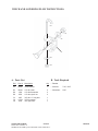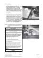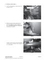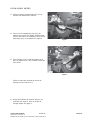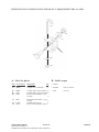
1
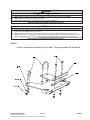
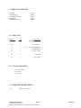
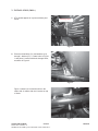
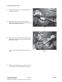
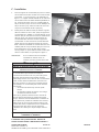
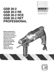
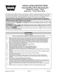
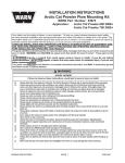
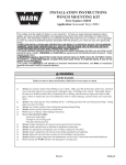
INSTALLATION INSTRUCTIONS PLOW MOUNTING KIT Part Number: 80260 Application: 2008+ Polaris Sportsman 550 and 850 XP Your safety, and the safety of others, is very important. To help you make informed decisions about safety, we have provided installation and operating instructions and other information on labels and in this guide. This information alerts you to potential hazards that could hurt you or others. It is not possible to warn you about all potential hazards associated with this product, you must use your own good judgment. CARELESS INSTALLATION AND OPERATION CAN RESULT IN SERIOUS INJURY OR EQUIPMENT DAMAGE. READ AND UNDERSTAND ALL SAFETY PRECAUTIONS AND OPERATING INSTRUCTIONS BEFORE INSTALLING AND OPERATING THIS PRODUCT. This guide identifies potential hazards and has important safety messages that help you and others avoid personal injury or death. WARNING and CAUTION are signal words that identify the level of hazard. These signal words mean: WARNING signals a hazard that could cause serious injury or death, if you do not follow recommendations. CAUTION signals a hazard that may cause minor to moderate injury, if you do not follow recommendations. This guide uses NOTICE to call attention to important mechanical information, and Note: to emphasize genera l information worthy of special attention. WARNING INJURY HAZARD Failure to observe these instructions could lead to severe injury or death. Alw ays Read the Plow Operator’s Manual, the Winch Operator’s Manual and all warning labels before operating. Alwa Alw ays use extreme caution when drilling on any vehicle. Make sure that all fuel lines, brake lines, electrical wires, and other Alwa objects are not punctured or damaged when/if drilling on the vehicle. Thoroughly inspect the area to be drilled (on both sides of material) prior to drilling, and relocate any objects that may be damaged. Failure to inspect the area to be drilled may result in vehicle damage, electrical shock, fire or personal injury. Alw ays wear safety glasses when installing this kit. A drilling operation will cause flying metal chips. Flying chips can cause eye Alwa injury. Alw ays use extreme caution when cutting and trimming during fitting. Alwa Alw ays remove jewelry and wear eye protection. Alwa Ne Nevver lean over battery while making connections. Ne out e electrical cables: Nevver rrout oute o Across any sharp edges. o Through or near moving parts. o Near parts that become hot. Alw a ys insulate and protect all exposed wiring and electrical terminals. Alwa Alw a ys install terminal boots as directed in installation instructions. Alwa Alw ays use appropriate and adequate care in lifting components into place. Alwa Alw ays insure components will remain secure during installation and operation. Alwa Alw ays tighten all nuts and bolts securely, per the installation instructions. Alwa Alw a ys operate the vehicle at a walking speed with the blade installed. Never exceed 5 mph (8 km/h), even with blade up. Alwa Alw ays plow cautiously, impact with hidden or stationary object may cause the vehicle to stop suddenly or go out of control. Alwa Ne Nevver operate the vehicle on slopes greater than 10 degrees with the plow installed. Ne Nevver stand or ride on the plow. Alw ays stay clear of moving parts and joints. Always keep others away when operating or adjusting plow. Alwa Alw ays perform regular inspections and maintenance on the plow mechanism, fasteners, cable and related hardware. Alwa Alw ays replace all worn or damaged parts before operating. Alwa Ne Nevver operate this WARN product with damaged or missing parts. Alw ays drive slowly over bumpy and rough terrain. Driving at speeds that cause the plow to bounce while in the up position can Alwa cause the winch to back-drive, causing the plow to work its way down. This may result in the plow impacting a stationary object and cause damage to the vehicle and operator injury or death. ays drive at speeds such that the plow does not bounce and be aware of the plow position while driving at all times. Alw Alwa Alw ays be aware that the purpose of the j-bolt is to break the connection between the plow and the winch, to prevent serious Alwa damage to the ATV if the plow is raised too high. The plow blade will drop suddenly if the j-bolt breaks, so always be sure there are no bystanders when you raise and lower the plow. Ne Nevver raise the top of the plow above the headlights of the ATV, as it may damage the vehicle and plow. Alw ays replace a deformed or broken j-bolt with the spare j-bolt included in the kit. Alwa WARN INDUSTRIES PAGE 1 ©2007 Warn Industries, Inc. WARN® and the WARN logo are trademarks of Warn Industries Inc. 80259A0 Caution Mo ving P ar ts Entanglement Hazard Moving Par arts Failure tto o obser o minor or moderat e injur observve these instructions could lead tto moderate injuryy. Always take time to fully read and understand the installation and Operations Guide included with this product. Never operate this product if you are under 16 years of age. Never operate this product when under the influence of drugs, alcohol or medications. Read installation and operating instructions thoroughly. Notice Equipment Damage Always refer to the Installation and Specification Guide, supplied in the winch kit, forall wiring schematics and specific details on how to wire this WARN product to your vehicle. Never overtighten the j-bolt to the bracket. Doing so will pinch the winch cable against the bracket, damaging the cable. Always put the end of the actuator cable through the slot in the Termination Bracket. Terminating the cable through any other hole in the bracket will cause the bracket to not function properly and will drastically reduce the life of the actuator cable. Read installation and operating instructions thoroughly. NOTES * Pictures used in these instructions are of a 2008 + Polaris Sportsman 550 and 850 XP WARN INDUSTRIES PAGE 2 ©2007 Warn Industries, Inc. WARN® and the WARN logo are trademarks of Warn Industries Inc. 80259A0 I. TABLE OF CONTENTS Parts List Tools Required Torque Specifications Installation Maintenance/Care page 3 page 3 page 3 page 4-7 page 8 II. PARTS LIST Reference A1 Qty 1 Description Plow Mounting Plate B1 2 5/16 - 18 U-bolt C1 C2 C3 2 8 6 5/16 - 18 x 3” Hex Head Bolt 5/16 Flat Washer 5/16-18 Lock nut D1 1 L Bracket E1 1 Spacer Plate III. TOOLS REQUIRED - 3/8” Drive ratchet - 1/2” socket - 1/2” wrench IV. TORQUE SPECIFICATIONS 5/16 17 lb. ft. (12.5 N-m) WARN INDUSTRIES PAGE 3 ©2007 Warn Industries, Inc. WARN® and the WARN logo are trademarks of Warn Industries Inc. 80259A0 V. INSTALLATION (2008 +) 1. ATV should appear as in picture without plow mount. Mounting Holes Figure 1 2. Place hex head bolts (C1) and washers (C2) through L bracket (D1). Locate holes in Figure 1 and place L bracket with bolts through holes, as shown in Figure 2. Figure 2 Figure 3 shows how it should look from the under side of vehicle with the L bracket on top of frame. Figure 3 WARN INDUSTRIES PAGE 4 ©2007 Warn Industries, Inc. WARN® and the WARN logo are trademarks of Warn Industries Inc. 80259A0 INSTALLATION CONT. 3. Place spacer plate (E1) over the bolts from the underside of vehicle. 4. Attach plow mount (A1) over the bolts and spacer and loosely attach washers (C2) and lock nuts (C3), as shown in Figure 4. Figure 4 5. Attach the rear of the mount using u-bolts (B1) by placing them over the frame and through the holes in the mount. Place the rest of the washers and lock nuts on ubolts. Figure 5 6. Tighten all hardware evenly, as shown in Figure 5. Reference torque specifications on page 3. WARN INDUSTRIES PAGE 5 ©2007 Warn Industries, Inc. WARN® and the WARN logo are trademarks of Warn Industries Inc. 80259A0 WINCH AND LOWERING PLOW INSTRUCTIONS: B1 C3 C2 A1 C1 B2 B3 A. Parts List B. Tools Required Ref Part # Description Qty • Ratchet A1 62845 J-bolt Bracket 1 • Sockets: 7/16”, 9/16” B1 B2 B3 35391 1320 6725 1/4” dia J-bolt 1/4” dia flat washer 1/4” dia nylock nut 2 2 2 • Wrenches: 9/16” C1 C2 C3 1827 11524 6779 3/8” dia x 1” long bolt 3/8” flat washer 3/8” nylock nut 1 1 1 WARN INDUSTRIES PAGE 6 ©2007 Warn Industries, Inc. WARN® and the WARN logo are trademarks of Warn Industries Inc. 80259A0 C. Installation 1. 2. Attach the J-bolt bracket (A1) to the center hole in the plow crossmember using a 3/8” dia x 1” long bolt (C1) as shown in figure 1. The bracket should be mounted on the blade side of the crossmember with the side flanges parallel to the ground. Terminate the bolt with a 3/8” dia flat washer (C2) and 3/8” dia nylock nut (C3). Tighten the bolt and nut to a recommended torque of 20 ft-lb (28 N-m). Run the winch cable over the roller fairlead and down to the J-bolt bracket (A1). Using a 1/4” dia J-bolt (B1), hook the loop on the end of the winch cable and slide the threaded end of the J-bolt through the round holes in the J-bolt bracket. The hook end of the J-bolt should slide into the slotted hole in the J-bolt bracket. Terminate the end of the J-bolt with a 1/4” dia flat washer (B2) and 1/4” dia nylock nut (B3). Tighten the nut until the winch cable is snug inside the J-bolt as shown in figure 2. C1, C2, & C3 A1 Figure 1 Installed J-bolt Bracket NOTE: Do not remove the winch hook installed on the end of the winch cable, simply slide it out of the way. Caution Mo ving P ar ts Entanglement Hazard Moving Par arts Failure to observe these instructions could lead to minor or moderate injury. Cable End The purpose of the J-bolt is to break the connection between the plow and ATV when the plow is subjected to high forces that could damage the plow or vehicle. The plow will drop instantly if the J-bolt breaks, so be sure there are no bystanders when operating the plow. Instances when the J-bolt might break are: B1, B2, & B3 Figure 2 J-bolt and Winch Cable • If the plow is raised too high and stalls. • If the operator is trying to lift too much material with the plow blade. In general, do not raise the top of the plow blade above the headlights of the vehicle. If the plow stalls, stop the winch immediately and lower the plow. After pushing material with the plow, backup the ATV prior to raising it. If the J-bolt breaks, replace it with the spare hardware found in this kit. Read the Plow Operators Guide for more information. Read installation and operating instructions thoroughly. Installation is now complete. Proceed to the next section entitle Maintenance/Care. WARN INDUSTRIES PAGE 7 ©2007 Warn Industries, Inc. WARN® and the WARN logo are trademarks of Warn Industries Inc. 80259A0 VI. MAINTENANCE/CARE • Inspect all metal parts on the plow, plow mount, and related hardware. Replace all parts that appears rusted or deformed prior to use. • Inspect all nuts and bolts on the plow, plow mount, and related hardware prior to each use. Tighten all nuts and bolts that appear to be loose. Stripped, fractured, or bent bolts or nuts need to be replaced immediately. • Check all cables prior to use. Replace cables that are worn or frayed. • Check all moving and rotating parts. Remove debris that may inhibit the part from moving freely. WARN INDUSTRIES PAGE 8 ©2007 Warn Industries, Inc. WARN® and the WARN logo are trademarks of Warn Industries Inc. 80259A0 INSTALLATION INSTRUCTIONS KIT DE MONTAGE DE LAME POUR Numéro de pièce: 80260 Application: 2008+ Polaris Sportsman 550 and 850 XP Votre sécurité et celle des autres est très importante. Afin de vous permettre de prendre des décisions éclairées dans le domaine de la sécurité, nous vous avons fourni des instructions relatives à l’installation et à l’utilisation du produit ainsi que d’autres informations figurant sur des étiquettes et dans ce guide. Ces informations attirent l’attention sur les risques de danger pouvant vous affecter ainsi qu’autrui. Nous ne sommes pas en mesure de vous mettre en garde contre tous les dangers potentiels associés à ce produit. Il vous incombe par conséquent de faire preuve de jugement. TOUTE INSTALLATION OU UTILISATION IMPRUDENTE PEUT ENTRAÎNER DES BLESSURES GRAVES OU ENDOMMAGER L’ÉQUIPEMENT. PRENEZ SOIN DE LIRE ET DE BIEN ASSIMILER LES CONSIGNES DE SÉCURITÉ ET D’UTILISATION DU PRODUIT AVANT DE L’INSTALLER ET DE L’UTILISER. Ce guide identifie les dangers potentiels et comporte des consignes de sécurité importantes qui permettent à vous et à autrui d’éviter les risques de blessures graves ou de mort. Les termes AVERTISSEMENT et MISE EN GARDE sont des indicateurs du niveau de danger. Signification des indicateurs : Le terme consignes. AVERTISSEMENT souligne un danger potentiel qui peut entraîner des blessures graves ou la mort si vous ne suivez pas les Le terme MISE EN GARDE souligne un danger potentiel susceptible d’entraîner des blessures mineures ou modérées si vous ne suivez pas les consignes. Ce guide utilise le terme AVIS pour attirer votre attention sur des informations mécaniques importantes, et le terme Remarque : pour souligner des informations générales qui méritent une attention particulière. AVERTISSEMENT RISQUES DE BLESSURES Le non-respect des instructions peut entraîner des blessures graves, voire mortelles. Lisez toujours les manuels de l’utilisateur de la lame et du treuil, ainsi que toutes les étiquettes de mise en garde, avant toute utilisation. Faites toujours extrêmement attention lorsque vous percez la carrosserie d’un véhicule. Veillez à ne pas perforer ni endommager les conduites de carburant, les conduites de frein, le câblage électrique ou tout autre objet lorsque vous percez. Inspectez soigneusement l’emplacement à percer (des deux côtés du matériau) avant de le faire, et déplacez tous les objets risquant d’être endommagés. Le fait de ne pas inspecter l’emplacement peut finir par endommager le véhicule, entraîner un choc électrique, un incendie ou des blessures. Portez toujours des lunettes de protection lors de l’installation du kit. Des éclats métalliques sont projetés durant le perçage. Ces éclats peuvent causer des lésions oculaires. Faites toujours très attention lorsque vous découpez ou ébarbez. Retirez toujours les bijoux et portez des lunettes de sécurité. Ne vous penchez jamais au-dessus de la batterie en procédant aux connexions. Ne faites jamais passer des câbles électriques : Sur des bords tranchants. Par des pièces mobiles ou à proximité. À proximité de pièces pouvant devenir chaudes. Isolez et protégez toujours tous les fils et bornes électriques exposés. Installez toujours les capuchons de borne de la manière indiquée dans les instructions d’installation. Faites toujours attention lorsque vous placez des composants. Assurez-vous toujours que les composants sont bien fixés durant l’installation et l’utilisation. Serrez toujours bien les écrous et les boulons conformément aux instructions d’installation. Conduisez toujours le véhicule, équipé de la lame, à vitesse de marche.Ne dépassez jamais 8 km/h (5 m/h) même si la lame est relevée. Utilisez toujours la lame avec prudence. Tout impact avec un objet caché ou fixe pourrait bloquer soudainement le véhicule ou le rendre incontrôlable. Ne conduisez jamais le véhicule équipé de la lame sur des pentes de plus de 10 degrés. Ne vous tenez jamais debout ou à califourchon sur la lame. Tenez-vous toujours à l’écart des pièces mobiles et des joints. Ne laissez jamais personne s’approcher durant l’utilisation ou le réglage de la lame. Effectuez toujours régulièrement les inspections et l’entretien du mécanisme de la lame, des fixations, du câble et du matériel connexe. Remplacez toujours toutes les pièces usées ou endommagées avant l’utilisation. Ne faites jamais fonctionner ce produit WARN avec des pièces endommagées ou manquantes. Conduisez toujours lentement sur les terrains cahoteux ou accidentés. Le fait de conduire à des vitesses qui secouent la lame alors qu’elle est en position relevée peut provoquer le déroulement du treuil, ayant pour effet de baisser la lame. La lame pourrait frapper un objet stationnaire et, par conséquent, endommager le véhicule et blesser l’opérateur, voire entraîner sa mort. Conduisez toujours à des vitesses telles que la lame n’est pas secouée et en étant toujours attentif à la position celle-ci. Gardez toujours à l’esprit que le crochet fileté a pour fonction de rompre la connexion entre la lame et le treuil pour éviter d’endommager sérieusement le VTT si la lame est relevée trop haut. Si le crochet fileté casse, la lame tombera brusquement. Assurez-vous donc que personne ne se trouve à proximité lorsque vous la relevez ou l’abaissez. Évitez toujours de relever le haut de la lame au-dessus des phares du VTT car cela peut endommager le véhicule et la lame. Remplacez toujours un crochet fileté déformé ou brisé par le crochet fileté neuf fourni dans le kit. WARN INDUSTRIES PAGE 9 ©2007 Warn Industries, Inc. WARN® and the WARN logo are trademarks of Warn Industries Inc. 80259A0 ATTENTION Danger de happement par des pièces mobiles Le non-respect des instructions peut entraîner des blessures mineures ou modérées. Prenez toujours le temps de bien lire et comprendre le manuel d’installation et d’utilisation inclus avec ce produit. Les personnes âgées de moins de 16 ans ne doivent jamais faire fonctionner ce produit. Ne faites jamais fonctionner ce produit sous l’effet de drogues, de l’alcool ou de médicaments. Veuillez lire attentivement les instructions concernant l’installation et l’utilisation. Avis Équipement endommagé Reportez-vous toujours au Guide d’installation et de spécification, fourni dans le kit de treuil, pour tous les schémas de câblage et des informations détaillées concernant la façon de brancher ce produit WARN sur votre véhicule. Évitez de trop serrer le crochet fileté sur le support. Cela coincerait le câble du treuil contre le support et l’endommagerait. Faites toujours passer l’extrémité du câble de relevage à travers la fente du support de terminaison. Si l’extrémité du câble est introduite dans un autre trou du support, cela empêchera le bon fonctionnement du support et réduira de façon radicale la durée de vie du câble de relevage. Veuillez lire attentivement les instructions concernant l’installation et l’utilisation. REMARQUE * Les images utilisées dans ces instructions sont celles du Polaris Sportsman XP 550, 850 modèle 2008+ WARN INDUSTRIES PAGE 10 ©2007 Warn Industries, Inc. WARN® and the WARN logo are trademarks of Warn Industries Inc. 80259A0 I. TABLE DES MATIÈRES Liste Des Pieces Outils Requis Couples De Serrage Installation Maintence/Entretien page page page page page 3 3 3 4-7 8 II. LISTE DES PIÈCES Référence Qté Description A1 1 Plaque de montage de la lame B1 10 Boulon en U 5/16 - 18 C1 C2 C3 2 8 6 Boulon à tête hexagonale 5/16 - 18 x 3 po Rondelle plate 5/16 Écrou de blocage 5/16 - 18 D1 1 Support en « L » E1 1 Plaque d’espacement III. OUTILS REQUIS - Clé à rochet 3/8 po - Douille 1/2 po - Clé 1/2 po IV. COUPLES DE SERRAGE 5/16 12,5 N-m (17 pi-lb) WARN INDUSTRIES PAGE 11 ©2007 Warn Industries, Inc. WARN® and the WARN logo are trademarks of Warn Industries Inc. 80259A0 V. INSTALLATION (2008 +) 1. Le VTT doit ressembler à l’image, sans kit de montage de lame. Trous de montage Figure 1 2. Enfilez les boulons à tête hexagonale (C1) munis de rondelles (C2) dans le support en « L » (D1). Repérez les trous de la figure 1 et fixez-y l’ensemble support en « L » et boulons, tel qu’illustré à la figure 2. Figure 2 La figure 3 montre à quoi le tout doit ressembler vu d’en dessous du véhicule, avec le support en « L » sur le cadre. Figure 3 WARN INDUSTRIES PAGE 12 ©2007 Warn Industries, Inc. WARN® and the WARN logo are trademarks of Warn Industries Inc. 80259A0 INSTALLATION (SUITE) 3. Placez la plaque d’espacement (E1) sur les boulons d’en dessous du véhicule. 4. Fixez le kit de montage de lame (A1) pardessus les boulons et la plaque d’espacement, et fixez sans serrer les rondelles (C2) et écrous de blocage (C3), tel qu’indiqué à la figure 4. Figure 4 5. Fixez l’arrière du kit à l’aide de boulons en U (B1) en plaçant ceux-ci sur le cadre et dans les trous du kit. Figure 5 Placez le reste des rondelles et écrous de blocage sur les boulons en U. 6. Serrez les fixations de manière uniforme, tel qu’illustré à la figure 5, selon le couple de serrage indiqué à la page 3. WARN INDUSTRIES PAGE 13 ©2007 Warn Industries, Inc. WARN® and the WARN logo are trademarks of Warn Industries Inc. 80259A0 INSTRUCTIONS CONCERNANT LE TREUIL ET L’ABAISSEMENT DE LA LAME: B1 C3 C2 A1 C1 B2 B3 A. Liste des pièces B. Outils requis Réf. No de pièce Description A1 62845 Support de crochet fileté B1 B2 B3 35391 1320 6725 Crochet fileté 1/4 po de diam. 2 Rondelle plate, 1/4 po de diam. 2 Écrou à frein élastique 1/4 po de diam. 2 C1 1827 C2 C3 11524 6779 Boulon 3/8 po de diam. x 1 po de long 1 Rondelle plate 3/8 po 1 Écrou à frein élastique 3/8 po 1 WARN INDUSTRIES Qté 1 PAGE 14 ©2007 Warn Industries, Inc. WARN® and the WARN logo are trademarks of Warn Industries Inc. • Cliquet • Douilles: • Clés: 7/16 po, 9/16 po 9/16 po 80259A0 C. Installation 1. 2. Fixez le support de crochet fileté (A1) au trou central de la traverse de la lame à l’aide d’un boulon de 3/8 po de diam. x 1 po de long (C1), tel qu’illustré à la figure 1. Le support doit être installé sur le côté lame de la traverse avec les brides latérales parallèles au sol. Terminez le boulon avec une rondelle plate de 3/8 po de diam. (C2) et un écrou à frein élastique de 3/8 po de diam. (C3). Vissez le boulon et l’écrou au couple recommandé de 28 N-m (20 pi-lb). Faites passer le câble du treuil par-dessus le guidecâble à rouleaux et vers le bas, jusqu’au support de crochet fileté (A1). Utilisez un crochet fileté de 1/4 po de diam. (B1) et accrochez la boucle à l’extrémité du câble du treuil, puis glissez l’extrémité filetée du crochet fileté dans les trous ronds du support de crochet fileté. Le côté crochet du crochet fileté doit glisser dans le trou allongé du support de crochet fileté. Terminez l’extrémité du crochet fileté avec une rondelle plate de 1/4 po de diam. (B2) et un écrou à frein élastique de 1/4 po de diam. (B3). Serrez l’écrou jusqu’à ce que le câble du treuil soit bien pris dans le crochet fileté, tel qu’indiqué à la figure 2. REMARQUE: C1, C2, & C3 A1 Figure 1 Support de crochet fileté installé Si un crochet de treuil est installé à l’extrémité du câble du treuil, ne l’enlevez pas mais poussez-le de côté. Mise en garde Danger de happement par des pièces mobiles Le non-respect des instructions peut entraîner des blessures mineures ou modérées. Le crochet fileté a pour fonction de rompre la connexion entre la lame et le VTT pour éviter que la lame soit soumise à des forces élevées pouvant endommager la lame ou le véhicule. Si le crochet fileté casse, la lame tombe soudainement. Assurez-vous donc que personne ne se trouve à proximité lorsque vous l’utilisez. Le crochet fileté peut casser dans les cas suivants : • Si la lame est relevée trop haut et qu’elle bloque. • Si l’opérateur essaie de soulever une charge excessive à l’aide de la lame. D’une façon générale, évitez de lever le haut de la lame au-dessus des phares du véhicule Si la lame bloque, arrêtez le treuil immédiatement et abaissez la lame. Après avoir poussé les matériaux avec la lame, faites reculer le VTT avant de soulever la lame. Si le crochet fileté casse, remplacez-le avec le matériel de rechange fourni dans le kit. Lisez le manuel de l’utilisateur de la lame pour de plus amples informations. l’extrémité du câble B1, B2, & B3 Figure 2. Crochet fileté et câble de treuil Veuillez lire attentivement les instructions concernant l’installation et l’utilisation. L’installation est à présent achevée. Passez à la section suivante intitulée « Maintenance/entretien ». WARN INDUSTRIES PAGE 15 ©2007 Warn Industries, Inc. WARN® and the WARN logo are trademarks of Warn Industries Inc. 80259A0 VI. MAINTENANCE/ENTRETIEN 1. Inspectez toutes les pièces du treuil, de la plaque de montage et le matériel de montage connexe avant toute utilisation. Remplacez tout matériel qui semble rouillé ou déformé. 2. Avant toute utilisation, inspectez tous les écrous et boulons du treuil, de la plaque de montage de lame et du matériel de montage connexe. Serrez bien tous les écrous qui en ont besoin. Les écrous et boulons foirés, fracturés ou tordus doivent être remplacés. 3. Vérifiez tous les câbles avant toute utilisation. Remplacez les câbles qui semblent usés ou effilochés. 4. Inspectez toutes les pièces mobiles ou rotatives. Retirez les débris pouvant gêner le libre mouvement des pièces. WARN INDUSTRIES PAGE 16 ©2007 Warn Industries, Inc. WARN® and the WARN logo are trademarks of Warn Industries Inc. 80259A0