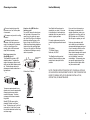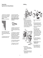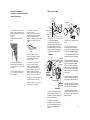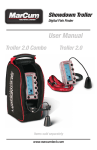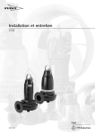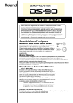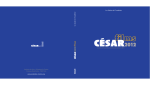
1
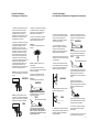
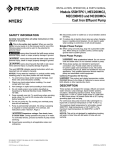
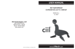
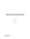
STEALTH STL200 Installation Manual STL200 STL200H1 Specifications: Easy Answers Tech Help Line: Call our experts 888 722-1000 Toll free fax: Send a fax to 888 722-1232 e-mail: Get answers promptly [email protected] rclighting.ca: Visit our website for product info The designs of RC Lighting fixtures are protected under Canadian, U.S. and international intellectual property laws, © 2010 RC Lighting Switching Capacity: 8 amps Voltage: 120 volts 1000 watts Incandescent 500 watts Fluorescent Detection Pattern: 50’ x 200˚ Time Adjustment: 5 seconds to 12 minutes Power Consumption: 1 watt Surge protection: I. E.C. specs UL Listing: Raintight Photoelectric Switch STL200HB Cautions: Mounting Plate: TURN OFF ALL POWER AT CIRCUIT BREAKER / FUSE PANEL. STL200 floodlight kits come prewired and assembled on the RC CU4 EZ plate, allowing for mounting on round, rectangular or octagonal surface or recessed boxes. Read entire Installation Manual before proceeding. All wiring should comply with local electrical codes and requires a qualified electrician. The total lighting load connected to Stealth must not exceed 8 amps (1000 watts incandescent or quartz, 500 watts fluorescent). To switch more wattage an electrician can install a relay. Mounting Bar Screws Hook CU4 EZ Plate Line Carrier Remote Control Systems such as X-10, Leviton or Radio Shack are incompatible with sensors and cause false activations. Do not install sensors on a circuit that feeds motor loads like kitchen appliances, HVAC equipment, washer/dryer, or garage door openers. Universal Mounting Bar Gasket O-Ring Gasket Sensor must be below and as far as possible away from lights. Sensor functions best when the direction of expected movement is across its detection pattern, not towards the sensor. Insert close-up plugs in unused holes Finishing Cap Center Screw Mount 6–12 feet high for optimum range and detection. 1 Contents of Accessory Kit How Does the STEALTH Work? • 2 Lens Masks • Indoor Switchplate Label • 3 Wire Nuts Stealth’s infrared sensor “sees” small temperature changes caused by the motion of people or cars within its protection zone and turns on lights automatically. It welcomes visitors and may deter intruders. STL200 How long do the lights stay on? Lights remain on as long as there is movement within the protection zone. Once the zone is vacated lights can be adjusted to remain on approximately 5 seconds up to 12 minutes. Since the lights are on only when needed, and the sensor uses only one watt the Stealth is extremely energy efficient. • Crossbar with Green Ground Screw • Hanging Hook • 1/2" Close Up Plugs (3) • Slotted Screws (4) • Finishing Cap • O-ring Gasket • Center Mounting Screw Can outdoor lights still be turned on with the light switch? Yes. Stealth can be controlled by a conventional indoor switch or circuit breaker. Lights can be turned on or off manually at night only. Manual Override Mode: (to keep lights on) Flip the switch twice slowly (off-on-off-on) within 2–3 seconds. To Resume Automatic Mode: Flip the switch once (off-on) within 2 seconds. Sensor will reset to Automatic Mode. • Foam Gaskets (2) • Metal Plate Masking the Lens How are the Time, Sensitivity and Photocell adjusted? Time: Sets the time that lights will remain on after the detection zone is vacated from approximately 5 seconds to 12 minutes. Factory Setting: 5–8 minutes Sensitivity: Increases or decreases the responsiveness and range of the sensor (Adjusts from 30% to 100%) Factory Setting: 100% Photocell: Located behind the lens. For night only operation, turn the knob all the way clockwise to (to the moon symbol). For 24 hour operation turn the knob all the way counterclockwise (sun & moon). Adjust clockwise to have the sensor come on later at dusk, counterclockwise to have it come on earlier. Factory Setting: Night Only Control Panel: Will Stealth detect animals? Stealth may detect large animals. Having animals trigger the sensor can give property a “lived-in” look. However, you can limit animal detection by turning down the sensitivity knob and/or by using the plastic lens mask supplied on the lower part of the lens. 13 2 Limited Warranty Choosing a Location Choose a location from which the sensor can “see” all the paths of movement. The sensor may be wall or ceiling mounted. As distance from the sensor increases, it will take more movement to be detected. For instance, at 10 feet, a half step will be enough, while at 40 feet several steps will be necessary. How large an area does Stealth200 detect? The Stealth200 provides a 200º detection pattern. To reduce the angle of coverage on either or both sides, use the plastic blinders provided. The blinders can also be cut sideways and used to reduce low or high detection. How does the LED Detection Indicator work? The red LED above the lens shows the logic state of the sensor. If the sensor is set for night only operation, the LED will go on for daytime detections without turning on the lights. At night, the LED will be on all the time, except during detections (at which time the controlled lights will go on). At night, the LED serves as a deterrent indicating a security device in operation. LED Detection Indicator Your Stealth will be replaced or repaired, at our option, if it proves to be defective in workmanship or materials within ten years from the date of original purchase. For repair replacement, return the product freight prepaid and insured to: RC Lighting 170 Ludlow Avenue Northvale, NJ 07647 The Stealth should be packed carefully. Please include you sales receipt and a description of the problem. If your unit is out of warranty or the damage is unrelated to the original manufacture, return your unit directly to us with a check for $30.00 (made out to RC Electric). We will repair or replace your unit. Under no circumstances shall we be liable for any incidental or consequential damages arising out of or in connection with the use or performance of this product or other indirect damages with respect to loss of property or revenue or cost of installation, removal or re-installation. This warranty gives you specific legal rights and you may also have other rights which vary from state to state. NOTE: THESE INSTRUCTIONS DO NOT COVER ALL DETAILS OR VARIATIONS IN EQUIPMENT NOR DO THEY PROVIDE FOR EVERY POSSIBLE SITUATION DURING INSTALLATION, OPERATION, OR MAINTENANCE. Detection Pattern 100˚ The sensor maybe swiveled in any direction to to cover the area desired. Always keep the sensor level to ensure full coverage. To reduce coverage, aim the sensor towards the ground. Stealth STL200 comes with a standard “Double Look Down” Lens. This lens has one “Look Out” zone and two “Look Down” zones, for excellent detection both at long and close range. Top View 30’ 10’ Side View 30’ 3 12 Technical Tips: Lights Turn On for Unknown Reasons Kit Wiring Red (pigtail) Red 1. Lights may turn on occasionally during rain, snow and windstorms because the sensor is detecting changes in temperature. Solution: Mount sensor in protected area. Black 3. You may not be aware that animals have triggered the sensor. Check sensor aiming to reduce nuisance triggering or mask the lower part of the lens with opaque weatherproof tape to create an “Animal Alley”. Power In If false detections are a constant problem, reduce sensitivity (turn counterclockwise) until the problem stops. 2. Tilt the sensor lower, it may be seeing distant objects moving. White Ground White Ground Red pigtail is only used to switch remote or additional fixtures. 10’ This is the “ A nim a l A lley” EZ Plate Black 50’ 4. Although it is surge and transient protected, the sensor may turn on occasionally during extreme voltage surges. 5. A possible source of “mysterious” sensor activations are strong local radio signals. Check for nearby CB, Ham, VHF radio transmitters or Cellular telephones. The sensor may be activated but will not be permanently impaired by these signals. 6. Check all the Solutions mentioned under “Lights Turn On and Off”. 1. Attach the Universal Mounting bar with the bar screws (provided) to the junction box. If you are attaching your STL200 kit to a surface mount weatherproof box, you must use the metal plate with the attached gasket. The gasket faces the Junction Box. Bar Screws Hook CU4 EZ Plate Insert close-up plugs in unused holes 5. Attach ground wire(s) to junction box grounding screw. Connect as shown in wiring diagram (pg 5). 6. Twist on wire nuts. Secure with electrical tape. 7. Align EZ Plate and metal mounting plate to insure proper seal. Tighten EZ Plate center screw (make sure O-Ring gasket is on the screw) to attach EZ Plate to the box. There are 2 screws supplied. Use the one which suits your assembly best. 8. Insert plastic Finishing Cap in the center of the EZ Plate for a weatherproof seal. Universal Mounting Bar Gasket O-Ring Gasket 7. Check items #2, 4, 5, 6 and 7 under “Lights Do Not Turn Off.” 4. Strip 1/2" of insulation from all leads. Center Finishing Screw Cap 2. Easy Wiring Tip: Use the “S” shaped Hands Free Hanging Hook to hold the EZ Plate during wiring. 9. Use silicone sealant around all openings to insure a weatherproof seal. 10. Screw in light bulbs. Turn on power. Conduct walk test to adjust sensor response (pg 6). 3. Bring power leads and sensor kit leads through holes in all gaskets into junction box. 11 4 Wiring Diagrams Technical Tips: Range Appears Limited White Basic Wiring Diagram Ground 1. Check that the sensor is level from side to side and pointed at the area you desire. If unit is tilted, part of the detection zone may be high in the air over people’s heads. Power In Red Black 3. Check that movement is not directly towards sensor. Sensor will see movement across its pattern more quickly. To fix, move the sensor. Sensor Basic Kit Wiring Note: Pigtail is only used to switch remote or additional light fixtures Red (pigtail) Power In WRONG! Black Less Sensitive Solution: Position sensor exactly level from side to side. Black White Ground Multiple Fixtures Red White Ground More Sensitive OK! Multiple fixtures may be wired to a single sensor. 2. Check that the sensor is not mounted too high. If mounted above 20 feet, much of the usable range will be lost. To handle loads greater than 1,000 watts, a qualified electrician should install a relay. 4. Check that movement far away and directly towards sensor is not entirely within one zone. Problem: Sensor will not detect until movement crosses zones No Detection Until Here 20' PATHWAY 40' Switchplate Label Switchplate label with STL200 self-adhesive backing. Attach Stealth operating instruction label to switchplate for quick and easy reference. Solution: Mounting at 6 feet to 12 feet allows maximum range. Power Quality It is not recommended to install sensors on a circuit that also feeds motor loads such as HVAC equipment, kitchen appliances, or garage door openers. The Stealth circuit is surge and transient protected to IEC specifications. However, if voltage varies significantly from 120 volts, sensor may malfunction. Solution: “Micro Adjust” sensor by moving sideways 1/4". This may move the zones to allow earlier detection. Detection Much Sooner 6-12' 50' 5 PATHWAY 10 Technical Tips: Lights Do Not Turn On 1. Check that lamps and fixtures work. Compare wiring to the wiring diagram in this manual. Check that the power is on. 2. If installing during daylight, remember that the sensor will provide 5 minutes of Test Time after power is turned on. After 5 minutes, the sensor will switch to Automatic Mode and will not work during daylight if the photocell control is turned to the night only position (moon symbol). Aiming and Walk Testing Lights Turn Off Too Quickly 1. Check if sensor is being “tricked” by reflected light. If lights controlled by the sensor shine or reflect into the photocell (located behind the lens) the unit will go on briefly, see its own light, and turn off “thinking” that it is daytime: Problems: Lights reflect into photocell lights shine directly into photocell WRONG! If you require 5 more minutes of Test Time, turn the power off for at least 10 seconds and back on again. If you require the sensor to operate both day and night, turn the center control knob counterclockwise to the sun and moon symbol. 3. Check that lights from another source, such as adjacent porch lights, garden lights or street lights are not in the sensor’s view. The sensor’s photocell may detect the light and deactivate “daylight”. If you desire the sensor to operate in higher ambient light levels, turn the photocell control (center knob) toward the sun symbol. 4. Was sensor wired hot? If so circuitry may have been damaged. Walk Test The purpose of the Walk Test is to check and adjust the coverage pattern. Stealth has a 5 minute Test Period which allows the sensor to be aimed and walk tested day or night. If you require 5 more minutes of Test Time, turn the power off for at least 10 seconds and back on again. During the Test Period, the sensor will keep lights on for 5 seconds each time it detects movement in its Detection Zone. The sensor will change to Automatic Mode after 5 minutes of testing. To enter Test Mode: Turn power off for at least 10 seconds and back on. Solution: Adjust photocell control (center knob) slightly counterclockwise, to allow operation at higher ambient light levels. Alternatively, move the lights or reflectors or mask the lens in the direction of the lights and/or reflections. 2. Check if “R” lamps, non-reflector “A” lamps or self-ballasted PL lamps are being used in a nonenclosed lampholder. If so, switch to reflector PAR floodlight lamps or Quartz floods so the sensor is not affected by stray light. If using PAR floodlights, consider using lower wattage, energy saving lamps. 9 1. Aim the sensor across the traffic pattern you want to detect. Start by aiming the sensor downward and then raise it slowly until the desired range is obtained. 2. Start outside the pattern and walk across the pattern until the lights go on. As distance from the sensor increases, it will take more movement to be detected. Start Finish 5. Repeat steps #2 thru #4 until you are satisfied with the coverage. 6. The “Time” control is factory set at approximately 5–8 minutes. This period starts after the movement in the detection pattern ceases. If less time is desired, turn the time control counterclockwise. For more time, turn the knob clockwise. 7. Stealth is factory set for night only operation. To obtain 24 hour operation, turn the photocell control full counter clockwise. Intermediate settings will adjust operation during dusk and dawn. 8. Your sensor is ready for operation. See the Technical Tips pages 7-11 if additional help is needed. Control Panel: 3. Adjust the sensor aiming as necessary to improve coverage. 4. To adjust the sensitivity turn knob gently. Less sensitivity (counterclockwise) may be desired if you wish to detect a limited area or if the sensor is being activated by wind, foliage or animals. More sensitivity (clockwise) will help cover a larger area. 6 Technical Tips: Lights Do Not Turn Off 1. Make sure that the sensor is not in Manual Override Mode. Turn power OFF for 10 seconds, then ON Sensor will be in Test Mode for approximately 5 minutes, then it will switch to Auto Mode with lights off and ready to detect movement. 2. Make sure sensor is not aimed at or mounted over something that would move or change temperature such as waving branches, water, air conditioners, windows or heating vents—even on neighboring property. You can test for infrared sources in the area by placing a box or bag over the sensor. Put sensor into test mode. Lights should stay off. Wave your hand inside bag in front of sensor. Lights should go on and then time out. If sensor operates properly when covered, check items #4–7. Problem: Sensor is triggered by unwanted movement or heat source. WRONG WRONG! Technical Tips: Lights Turn On and Off Inappropriately 3. Make sure sensor and lights are mounted firmly and do not move even slightly when touched. If they move, tighten all screws. 4. Make sure sensor is not mounted on an unstable object such as a tree or pole that will move in the wind. Problem: Movement of tree triggers sensor. 1. Make sure the sensor is installed on its own dedicated circuit, free of motor loads such as HVAC equipment, kitchen appliances or garage door openers. 2. It is not recommended to wire sensors in parallel. More than one sensor wired together makes them difficult to troubleshoot. Disconnect multiple sensors and test separately. 3. Keep all people completely out of the detection pattern to make sure the sensor is not detecting them. Solution: Mount on stable surface. 5. Was sensor wired hot? If so, circuitry may have been damaged. 6. Make sure sensor is not aimed within 20 feet of a road. Problem: Passing cars activate sensor. 4. Make sure sensor is located below and as far as possible from its lights. Heat from the lights may trigger the sensor. WRONG! WRONG! Solution: (1) Aim sensor away from movement or (2) mask lens as in the direction of the source and/or (3) lower sensitivity control setting. Solution: A 20 foot safety zone and lower sensitivity are recommended to avoid activation from passing cars. OK! 20’ Safety Zone Solution: A 20 foot safety zone and reduced sensitivity are recommended to avoid activation from passing cars. OK! 20’ Safety Zone 7. Heavy rain, snow or high winds may activate the sensor occasionally. Reduce sensitivity control slightly until problem stops. 8. Make sure lights are not reflecting back into sensor. Check for white or reflective surfaces close to the sensor. OK! Solution: Aim sensor away from reflective objects, or move the objects and lower sensitivity. 5. Moths can be attracted to the lights and fly close to the sensor causing triggering. Reducing the sensitivity may help. 7 WRONG! Solution: Move sensor below and away from the lights. OKOK! 7. Make sure heat from lights is not triggering sensor. Make sure the sensor is below and as far as possible away from lights. 6. Make sure sensor is not aimed within 20 feet of a road or sidewalk. Passing cars will activate sensor. 9. Self ballasted PL lamps may cause cycling (on-off). 10. Check Solutions #2, 4, 5, 6, and 7 under “If Lights Do Not Turn Off”. 8 ������� �������������������������� STL200 STL200H1 STL200HB Caractéristiques ��������������� : Switching Capacity: 8 amps Capacité de commutation : 8A Voltage: 120 volts 120 volts Tension : 1000 wattsIncandescence Incandescent de 1 000 watts 500 watts Fluorescent Fluorescence de 500 watts Configuration de détection Detection Pattern: 50’: x 200˚ 50 pi x 200 pi Réglage de la minuterie 5 : seconds 5tosecondes à 12 minutes Time Adjustment: 12 minutes Consommation : 1 watt Power Consumption: 1 watt : Spéc. I. E.C. Protection contre les surtensions Interrupteur photoélectrique résistant à la pluie Homologation UL : Surge protection: I. E.C. specs UL Listing: ���� ������� ���� ���� ����� ���� ���� ���� ������� �������������� Call our experts ��� �������� Send a fax to ��� �������� Get answers promptly ������������������� Visit our website for product info The designs of RC Lighting fixtures are protected under Canadian, U.S. and international intellectual property laws, © 2010 RC Lighting Les concepts à l’origine des luminaires RC Lighting sont protégés en vertu des lois sur la propriété intellectuelle des États-Unis, du Canada et d’autres pays. © 2010 RC Lighting Raintight Photoelectric Switch ���������� ��������������� COUPER COURANT AU TURN OFFLE ALL POWER AT DISJONCTEUR / PANNEAU DE CIRCUIT BREAKER / FUSE PANEL. FUSIBLES. Les trousses de projecteurs STL110 floodlight kits come preSTL200 sont précâblées et RC wired and assembled on the assemblées la plaque RC CU4 CU4 EZ plate,sur allowing for mounting EZ, permettant le montage sur les on round, rectangular or octagonal surfaces rectangulaires surface orrondes, recessed boxes. ou octogonales ou dans les boîtes encastrées. Read Installation Manual ▪ Lire le entire manuel d’installation au before proceeding. complet avant de continuer. All wiring shoulddoit comply with le câblage être conforme ▪ Tout localcodes electrical codes and requireset aux locaux de l’électricité Montage �������� a qualified electrician. par un électricien doit être effectué compétent. The total lighting load connected to Stealth must not exceed 8 amps Vis���� de barre ▪ La charge d’éclairage totale ������ (1000 wattsauincandescent or quartz, raccordée Stealth ne doit pas 500 watts 8fluorescent). To switch A (incandescence dépasser ou Insérer les ������ more wattage electrician can Crochet ����� ������� CU4 EZ bouchons quartz de 1000anwatts, fluorescence �������� Plaque dans les install relay. Pour accroître la de 500awatts). ����� �������� trous puissance, un électricien peut ������ inutilisés Line Carrier Remote Control ����� installer un relais. Systems such as X-10, Leviton or Shack areàincompatible ▪Radio Les systèmes commande with andreliés cause activations. àsensors distance aufalse câblage, comme X-10, Leviton ou Radio Do not install sensors on a Barre de Shack sont incompatibles avec les ��������� montage circuit that feeds motor loads ������������ détecteurs et provoquent de faux universelle like kitchen appliances, HVAC déclenchements. equipment, washer/dryer, or garage ������ Joint openers. ▪door Ne pas installer sur un circuit Joint torique ������������� quiSensor alimente des moteur must becharges below and as far comme des appareils de cuisine, de Capuchon de ��������� as possible away from lights. l’équipement de climatisation, une ��� finition laveuse/sécheuse ou un ouvreSensor functions best when the porte de garage. direction of expected movement is Vis centrale ������� ����� across its detection pattern, not ▪ Le détecteur doit être sous les towards the sensor. lampes et aussi loin que possible deMount celles-ci. 6–12 feet high for optimum range and detection. ▪ Le détecteur fonctionne mieux si le mouvement prévu survient à l’intérieur de sa configuration de détection et non en direction du détecteur. ▪ Installer entre 6 et 12 pieds de hauteur pour une portée et une détection optimales. � Contenu la trousse d’accessoires �������� de �� ��������� ��� ��������� ����� ������ �� ��� ���� �� ������ ���� ��� ��� ������� 1. Check that lamps and fixtures work. Compare to the wiring dewiring lentille •• 22 masques Lens Masks diagram in this manual. Check that d’interrupteur •• Étiquette Indoor the powerSwitchplate isde on.plaqueLabel • 3 intérieure Wire Nuts 2. If installing during daylight, • 3 connecteurs remember that the sensor will provide 5 minutes of Test Time after power is turned on. After 5 minutes, the sensor will switch to Automatic Mode and will not work during • Crossbar daylight if the photocell control is with to Green Ground turned the night onlyScrew position •• Barre transversale (moon symbol). Hanging Hook à vis de mise à laClose terre vertePlugs (3) 1/2" If•you require 5Up more minutes of • Crochet de fixation Test Time, Screws turn the(4) power off for • Slotted at• Bouchons least 10 seconds back de 1/2 and po (3) • Finishing Cap on again. à filets interrompus (4) •• Vis O-ring Gasket • you Capuchon de If• require thefinition sensor to operate Center Mounting Screw both day toriques and night, • Joints (2)turn the center control knob counterclockwise to • Vis deand montage centrale the sun moon symbol. • Check Foam Gaskets (2)from another 3. that lights source, • Metalsuch Plateas adjacent porch lights, garden lights or • Joints de mousse (2)street lights are not in the sensor’s view. The • Plaquephotocell de métalmay detect the sensor’s light and deactivate “daylight”. If you desire the sensor to operate in higher ambient light levels, turn the photocell control (center knob) toward the sun symbol. 4. Was sensor wired hot? If so circuitry may have been damaged. Principe de fonctionnement de STEALTH ��� ���� ��� ������� ����� ������ ��� ���� ������� Le détecteur à infrarouge Stealth “voit” les petits écarts de température produits par le mouvement des personnes ou des voitures circulant dans sa zone deStealth’s détection infrared et allumesensor les lampes “sees” automatiquement. Il accueille les caused small ���� temperature changes ���� visiteurs et éloigne les intrus. 1. Check if sensor is being “tricked” by reflected light. If lights controlled by the sensor shine or reflect into the photocell (located behind the lens) the unit will go on briefly, see its own light, and turn off “thinking” that it is daytime: by the motionofofthe people cars The purpose Walk or Test is within its protection zone and turns ������ to check and adjust the coverage Pendant combien de temps l’éclairage on lights automatically. welcomes pattern. Stealth Test reste-il allumé ? has a 5 Itminute visitors and may deter Period which allows theintruders. sensor Les lumières restent allumées aussi to be aimed and walk testedest day or longtemps que le mouvement ��� dans ���� ��zone ���de ������ ���� ��� night. If you require 5protection. more minutes détecté la Une Lights remain ononas long as there fois laTest zone libérée, peut régler les foris of Time, turn the power off luminaires à and rester allumer movement within the protection at least de 10 manière seconds back on entre 5 secondes etzone 12Test minutes. Comme zone. Once isPeriod, vacated again. Duringthe the the lessensor luminaires s’allument seulement lights can adjusted to remain willbe keep lights on for 5 auon besoin et que le détecteur consomme approximately 5 seconds up moveto 12 seconds each time it detects seulement un watt, the le Stealth est minutes. Since lights areThe on ment in its Detection Zone. extrêmement économe d’énergie. ��������� Lights reflect into photocell, or lights shine directly into photocell ������ only when and the sensor sensor will needed, change to Automatic uses only one watt the Stealth is Modeque after minutes of testing. Est-ce les5lampes extérieures extremely efficient. peuvent tout energy de même être allumées To enter Test ?Mode: par l’interrupteur ��� ������ Turn power for at ����� least�� ������ Oui. Le ������� Stealth off peut être commandé par �� ���� ���intérieur �����back ������� seconds and on. ou un un10 interrupteur ordinaire Yes. Stealth can allumer be controlled by a On peut ou éteindre disjoncteur. les1. lampes manuellement uniquement conventional indoor switch circuit Aim the sensor across theortraffic la pattern nuit. breaker. Lights can turned on or you want to be detect. Start by Mode contournement manuel off manually at night only.: aiming the sensor downward and (pour garder luminaires allumés) Manual Override Mode: then raiseles it slowly until the desired Actionner l’interrupteur deux (to keep lights on) Flip the switch range islentement obtained. fois (arrêt-marche-arrêt-marche) dans twice slowly (off-on-off-on) within les2.2-3 secondes. outside the pattern and 2–3Start seconds. Pour reprendre le mode automatique walk the pattern until the: To across Resume Automatic Mode: Actionner une fois l’interrupteur lights go on. As distance from the Flip the switch (off-on) within (arrêt-marche) dansonce les 2will secondes. sensor increases, it will take more 2 seconds. Sensor reset to Le détecteur se remet en mode movement to be detected. Automatic Mode. automatique. ��������� Adjust photocell control (center knob) slightly counterclockwise, to allow operation at higher ambient light levels. Alternatively, move the lights or reflectors or mask the lens in the direction of the lights and/or reflections. 2. Check if “R” lamps, non-reflector “A” lamps or self-ballasted PL lamps are being used in a nonenclosed lampholder. If so, switch to reflector PAR floodlight lamps or Quartz floods so the sensor is not affected by stray light. If using PAR floodlights, consider using lower wattage, energy saving lamps. Masquer lentille ������� ���la ���� Comment régler la minuterie, la ��� ��� ��� ��� ����� ����������� �������������������������������������� sensibilité et la photocellule ? ��������� ��������� ▪ Minuterie : Programme le temps Time: Sets the time that lights 5. Repeat steps #2 thru #4 until you durant lequel les luminaires restent will remain on after the detection allumés une fois que la zone de are satisfied with the coverage. zone is vacated from approximately détection est libérée entre 5 secondes 5et seconds to 12 minutes. 6. Theminutes. “Time” control is factory set 12 Factory Setting: at approximately 5–8 minutes. Réglage de l’usine5–8 : 5 àminutes 8 minutesThis Sensitivity: Increases or la period starts after the movement in ou réduit ▪ Sensibilité : Accroît decreases responsiveness the detection pattern ceases. If less réaction et lathe portée du détecteur and range (réglage de of 30 the % turn àsensor 100the %)time control time is desired, Réglage de l’usine : 100 %more time, (Adjusts from 30% to counter-clockwise. For100%) ▪ Photocellule Derrière Factory 100%la lentille. Pour turn the Setting: knob: clockwise. le Photocell: fonctionnement la nuitbehind seulement, Located the 7. Stealth is factory set for night tourner le night bouton complètement àturn lens. For only operation, only operation. To obtain 24 hour droite à (symbole de lune). Pour the knob all the way clockwiseleto fonctionnement 24 le operation, turn theheures, photocell (to the moon symbol). Fortourner 24 control hour bouton complètement à gauche (soleil full counter-clockwise. Intermediate operation turn the knob all the way et lune). will adjust operation during settings counterclockwise Réglerand à droite pour(sun que & le moon). détecteur dusk dawn. Adjust clockwise the sensor fonctionne plus tardtoauhave crépuscule et à come on later at dusk, countergauche qu’ilisfonctionne tôt. 8. Your pour sensor ready for plus operation. clockwise have: Tips itNuit come on earlier. Réglage deto l’usine seulement See the Technical pages 7-11 Setting: Only ifFactory additional help Night is needed. ������� ������ Panneau de commande : ������� ������ 3. Adjust the sensor aiming as Stealth détectera-t-il les animaux ? Lenecessary ���� ������� �������� to������ improve coverage. LeStealth Stealth may peut détecter les gros detect large animals. 4. To adjust sensitivity knob animaux. Le faitthe quetrigger des animaux Having animals the turn sensor déclenchent le détecteur peut contribuer gently. Less sensitivity (countercan give property a “lived-in” look. à donner l’impression laanimal maison est clockwise) maycan beque desired if you However, you limit habitée. Ondetect peut cependant limiter la if wish to a limited area or detection by turning down the détection des animaux en tournant by le the sensor is being activated sensitivity knob and/or byplaçant using bouton de sensibilité et/ou en More wind, foliage or animals. plastic mask supplied le the masque de lens lentille en plastique fourni sensitivity (clockwise) will help on the lower part of de the dans la partie inférieure lalens. lentille. cover a larger area. �� SENSIBILITÉ Nuit PHOTOCELLULE MINUTERIE Fonctionnement Fonctionnement 24 heures la nuit � � � ������� �������� Choisir un emplacement Choisir un emplacement �������������������� ▪ Choisir un aendroit duquel le which détecteur Choose location from peut “voir” toutes les voies the sensor can “see” all d’accès. the paths of movement. ▪ Le détecteur peut être fixé au mur ou au The plafond. sensor may be wall or ceiling mounted. ▪ Plus la distance par rapport au As distance from the détecteur augmentera, plussensor le increases, itsera willdifficile take more movemouvement à détecter. Par exemple, à 10detected. pieds, un For demi-pas suffit, ment to be instance, alors il fautwill plusieurs pas. at 10qu’à feet,40apieds, half step be enough, while at 40 feet several Le Stealth100 protège une zone de steps will be necessary. quelle dimension ? Le Stealth200 procure une configuration ��� ����� �� ���� ���� de détection de 200 º. Pour réduire ���������� ������� l’angle de protection d’un côté ou de The Stealth200 provides l’autre, ou des deux, utiliser a les200º masques detection pattern. the de plastique fournis. To Onreduce peut aussi angle of coverage on either or latérale both découper les masques de façon sides, use the plastic blinders providet les utiliser pour réduire la détection basse et élevée. ed. The blinders can also be cut sideways and used to reduce low or high detection. Principe de l’indicateur de détection DÉL ��� ���� ��� ��� ��������� La DÉL rouge au-dessus de la lentille ��������� ����� indique l’état logique du détecteur. The red LED above the lens shows Si le détecteur est programmé pour the logic state of the sensor. If the fonctionner la nuit seulement, la DÉL sensor set les for détections night onlydeoperas’allumeispour jour sans tion, theles LED will go on for daytime allumer luminaires. La nuit, la DÉL detections without on the reste allumée en toutturning temps, sauf durant lights. At night, the que LEDleswill be on les détections (alors luminaires all the time, except during detections raccordés s’allument). La nuit, la DÉL prévient de sécurité est (at whichqu’un timedispositif the controlled lights en fonction. will go on). At night, the LED serves as a deterrent indicating a security device in operation. Indicateur de LED DetectionDÉL détection Indicator Le Stealth serawill remplacé ou réparé, Your Stealth be replaced or à notre discrétion, est jugé repaired, at ours’il option, if itcomporter proves desbe défauts de main-d’œuvre ou deor to defective in workmanship matériaux dans dixyears années qui the materials withinlesten from suivent la date d’achat originale. date of original purchase. Pour obtenir une réparation ou un For repair replacement, remplacement, retourner lereturn produitthe port product freightà prepaid and insured payé et assuré : to: RC Lighting 170 Lighting Ludlow Avenue RC Northvale, NJAvenue 07647 170 Ludlow Northvale, NJ 07647 Le Stealth doit être emballé avec soin. Prière d’inclure le coupon de caisse et The Stealth should be packed une description du problème. carefully. Please include you sales receipt and a description of the problem. l’unitéunit n’est protégée par or la IfSiyour is plus out of warranty garantie ou que les dommages ne sont the damage is unrelated to the pas reliés à sa fabrication originale, original manufacture, return your nousdirectly retourner directement, unit tol’unité us with a check for accompagnée d’un chèque de 30,00 $ (à $20.00 (made out to RC Electric). l’ordre de RC Lighting). We will repair orou replace your unit. Nous réparerons remplacerons votre unité. Under no circumstances shall we beneliable for any or Nous pourrons êtreincidental tenus consequential responsables endamages aucun casarising des out of or in connection with use or dommages accidentels ou the accessoires découlant de l’utilisation ou du or performance of this product rendement de ce produit ou d’autres other indirect damages with respect dommages indirects or relativement à la to loss of property revenue or perteof deinstallation, propriété ou removal de revenus cost or ou aux coûts d’installation, de retrait ou de re-installation. This warranty gives réinstallation. La présente garantie vous you specific legal rights and you confère des droits légaux précis et vous may also have otherdroits rightsqui which pouvez avoir d’autres varient vary stateà to state. d’unefrom province l’autre. �������������������������������������������������� ��������������������������������������������������� ���������������������������������������������� �������������������������� Configuration de détection Detection Pattern 100 pi 100˚ Thedétecteur sensor maybe swiveled in any Le peut être orienté dans toutes les to directions la zone direction to coverpour the couvrir area desired. le détecteur voulue. Always Toujours keep themaintenir sensor level to de niveau obtenir la ensure fullpour coverage. Topleine reduce couverture. Diriger détecteur vers le coverage, aim thelesensor towards sol réduire la couverture. thepour ground. Le Stealth STL200comes est équipé Stealth STL200 withd’une a lentille standard “double vers le bas”. standard “Double Look Down” Cette comprend une“Look zone “vue Lens.lentille This lens has one Out” extérieure” et deux zones “vers zones, le bas” zone and two “Look Down” pour une excellente détection à longue for excellent detection both at long et à courte distance. and close range. Vue supérieure Top View de 30�30 pi 1010� pi Vue latérale Side View de 30�30 pi 3 12 Conseils techniques : ��������� ����� ��������� ����� Les lampes s’allument pour ������� des ������ ���� �� ��� ������� ������ �� ��� ������� ������� raisons���� inconnues ���������� Câblage ��� ������de trousse ��� ������ ��������������� Rouge ������� (queue de ��������� cochon) ������� ��������� Rouge ��� 1. luminaires peuvent en cas 1.Les Lights may turn on s’allumer occasionally de demay neige ou de de vent 1. pluie, Lights turn ontempête occasionally during rain, snow and windstorms car le détecteur détecte les changements during rain, and because thesnow sensor is windstorms detecting de température. because thetemperature. sensor is detecting changes in Solution : in temperature. changes Solution: Installer le détecteur dans un endroit Solution: Mount sensor in protected area. protégé. Mount sensor in protected area. 3. se peut des 3. IlYou mayque not beanimaux aware aient that déclenché le détecteur. 3. You may not be aware animals have triggered thethat sensor. Vérifier l’orientation du détecteur afin de animals have triggered sensor. Check sensor aiming tothe reduce réduire déclenchements intempestifs Checkles sensor aiming reduce nuisance triggering orto mask the TURN OFF ALL POWER AT ou masquer la inférieure de la nuisance or mask the lower parttriggering ofpartie the lens with opaque CIRCUIT BREAKER / FUSE PANEL. lentille avec du ruban opaque résistant aux lower part of the with opaque weatherproof tapelens to create an intempéries pour créer un “passage pour weatherproof “Animal Alley”.tape to create an animaux”. Read entire Installation Manual “Animal Alley”. before proceeding. 10��� pi ��� All wiring should comply with local electrical codes and requires 50 Passage pour ���pi ������� ����qualified electrician. � � � �� � a �� � ����� ��� animaux ������� ���� � � ��� � �� �The ����� total lighting load connected toitStealth must not exceed 8 amps s’il est protégé contre 4. 4. Même Although is surge and les transient (1000 wattsmay incandescent surtensions et parasites, le détecteur 4. Although itlesissensor surge and transient protected, the turn on or quartz, peut s’allumer àduring l’occasion lors des 500 wattsextreme fluorescent). protected, the sensor may turn onTo switch occasionally voltage surtensions extrêmes. more wattage an electrician occasionally during extreme voltage can If false detections are a constant En cas de détections intempestives If false detections are a constant problem, reduce (turn constantes, réduire lasensitivity sensibilité (tourner problem, reduce sensitivity (turn counterclockwise) until theleproblem vers la gauche) jusqu’à ce que problème counterclockwise) until the problem stops. soit corrigé. stops. 2.Incliner Tilt thele sensor it may bele détecteurlower, davantage vers 2. 2. Tilt the sensor lower, itobjets mayqui be bas - celui-ci peut objects capter des seeing distant moving. bougent distance. seeing àdistant objects moving. surges. surges. install a relay. 5. Les puissants signaux radio locaux 5. A possible source of “mysterious” Line Carrier Remote Control peuvent provoquer l’actionnement 5. A possible ofstrong “mysterious” sensor activations are local Leviton or Systems such as X-10, “mystérieux” du source détecteur. Vérifier la sensorsignals. activations areforstrong local radio Check nearby présence de Radio radios bande publique etCB, Shack are incompatible with radio signals. Check for cause nearby CB, Ham, VHF radio transmitters amateur, émetteurs deand radio VHF or oufalse de activations. sensors Ham, VHF radio transmitters or Cellular telephones. sensor téléphones cellulaires à The proximité. Le may Do actionné, not install sensors on a Cellular telephones. sensor may détecteur peut être mais n’est pas be activated but will The not be permacircuit that feeds motor loads altéré enimpaired permanence par ces signaux. be activated butby will not be permanently these signals. like kitchen appliances, nently impaired by these signals. HVAC lesSolutions solutions données sousor garage 6. washer/dryer, 6. Vérifier Checktoutes allequipment, the mentioned “Les lampes s’allument et s’éteignent”. openers. 6. Check alldoor the Solutions under “Lights Turn On andmentioned Off”. under “Lights Turn On and Off”. Sensor2,must 4, 5, 6be et 7below sous and as far 7. Vérifier les solutions 7. Check items #2, 4, 5, 6 and 7 lights. as possible away from “Si les luminaires ne s’éteignent pas”. 7. Check itemsDo #2,Not 4, Turn 5, 6 and under “Lights Off.”7 under “LightsSensor Do Notfunctions Turn Off.”best when the direction of expected movement is across its detection pattern, not towards the sensor. Mount 6–12 feet high for optimum range and detection. �� �� Noir ����� Entrée électrique ����� �������� �������� ����� Blanc ����� Mise ������ à la terre ��� Plaque EZ �� ����� Noir ����� ����� �� ����� Blanc ����� Mise à la terre ����� ������ ������ ������ STL110 floodlight kits come preUtiliser la queue de cochon rouge seulement pour Red pigtail is only used to switch or wired and assembled onremote the RC commander à distance ou additionnels. additional Red pigtailfixtures. is les onlyluminaires used to switch remote or CU4 EZ plate, allowing for mounting additional fixtures. 1. Fixer larectangular barre de montage 1. Attach the Universal Mounting on round, or octagonal universelle au moyen des vis(providde 1. Attach the Mounting bar with theUniversal bar boxes. screws surface or recessed barre à la screws boîte jonction. bar(fournies) with bar ed) to thethe junction box.deIf(providyou are Si ed) on fixe la trousse STL200 une to the junction box. kit Ifàyou attaching your STL200 to aare boîte étanche murale, on doit attaching your STL200 kit utiliser to box, a surface mount weatherproof la plaque de métal à joint intégré. Le surface mount weatherproof you must use the metal platebox, with �������� joint faitattached face use à la gasket. boîte de The jonction. you must the metal plate with the gasket the attached gasket. The gasket faces the Junction Box. ���� Vis de barre faces the Junction Box. ������ ��� ������ ��� Crochet ����� ������ ���� ���� CU4 EZ ������� Plaque ��� �� ����� ����� ��� �� ����� Insérer les ������ bouchons ������ �������� dans les �������� �������� ������ trous ����� �� ������ �������� inutilisés ������ ����� ����� �� ����� ������ ����� Barre de ��������� ��������� montage ������������ �������� universelle ��������� ��� �������� ��� ������ Joint ������ ������ Joint torique ������������� ������������� ������������� Capuchon ��������� ��������� ��� finition ������ de ��� ����� ������ ��������� ��� ����� Vis centrale ������� 2. Easy Wiring Tip: ����� 2. de simple 2. Conseil Easy Wiring Tip: Hands Use the “S”raccordement shaped Free : Utiliser le de fixation “S” à Use thecrochet “S” shaped Hands Free Hanging Hook to hold theen EZ Plate mains libres pour retenir plaque EZ Hanging Hook to holdlathe EZ Plate during wiring. pendant raccordement. duringlewiring. 3. Bring power leads and sensor kit 3. Bring power sensor kit leads through holesand in all gaskets 3. Acheminer lesleads conducteurs leadsjunction through holes in all gaskets into d’alimentation etbox. les conducteurs de into junction box. par les trous la trousse de détecteur de tous les joints dans la boîte de jonction. � 4. Strip Dénuder po d’isolation 1/2" 1/2 4. of insulation fromde alltous lesleads. fils. 1/2" of insulation from all 4. Strip leads. 5. wire(s) to junction 5. Attach Fixer leground ou les fils de terre à la 5. Attach ground wire(s) to junction grounding screw. Connect visbox de mise à la terre de la boîte de box grounding screw. Connect as shown in wiring (pg 5). jonction. Raccorder teldiagram qu’illustré dans as shown wiring diagram (pg 5). le schéma deinraccordement (page 5). 6. Twist on wire nuts. Secure with 6. Twist on wire nuts. Secure with electrical tape. 6. Visser les connecteurs de fils. Fixer electrical tape. en place avec du ruban d’électricien. 7. Align EZ Plate and metal 7. mounting Align EZ Plate metal plateand to insure 7. Aligner la plaque et plaque mounting plate toEZ insure proper seal. Tighten EZlaPlate decenter fixationscrew de métal pour sceller. proper seal. Tighten EZbien Plate (make sure O-Ring Serrer la vis centrale desure la to plaque center screw (make O-Ring gasket is on the screw) attach EZgasket (s’assurer lescrew) joint torique is to onque thebox. to attach EZ Plate the There arese trouve sur lato vis) fixer la plaque EZ Plate thepour box.Use There are 2 screws supplied. the one EZ2 àscrews la boîte. Deux visUse sontthe fournies. supplied. one which suits your assembly Utiliser convient le mieux à whichcelle suitsqui your assembly best. l’assemblage. best. 8. Insert plastic Finishing Cap in 8. Insert plastic Finishing Cap in ade center of the EZ de Plate for 8. the Insérer le capuchon finition center of the EZla Plate for a the weatherproof seal. plastique au centre de plaque EZ weatherproof seal.les intempéries. pour protéger contre 9. Use silicone sealant around all 9. openings Use silicone insure sealanta around all 9. Appliquer to un calfeutrant de silicone openings to insure a weatherproof autour de toutes seal. les ouvertures pour weatherproof seal. bien sceller contre les intempéries. 10. Screw in light bulbs. Turn on 10. power. Screw in light bulbs. on Conduct walk Turn test to 10.power. Visser les ampoules en Conduct walk test to6). adjust sensor response (pgplace. Mettre tension. Effectuer adjustsous sensor response (pg 6).un test de marche pour régler la réponse du détecteur. (page 6). � � Schémas de raccordement ������ �������� Blanc ����� Schéma de raccordement ����� ������ ������� de base cted area. a constant ivity (turn the problem , it may be moving. Mise à la terre ������ Entrée électrique ����� �� Rouge ��� ��� ������ ����� Noir Détecteur ������ �� ������� ������� occasionally windstorms detecting e. Conseils techniques : ��������� ����� La portée semble limitée ����� ������� ������� Câblage trousse de base ����� ���de ������ Note:: Pigtail used switch Note Utiliserislaonly queue detocochon remote or additional light fixtures seulement pour commander les luminaires à distance ou additionnels 3. You may not be aware that animals have triggered the sensor. Check sensor aiming to reduce nuisance triggering or mask the lower part of the lens with opaque Plusieurs luminaires �������� weatherproof tape to�������� create an “Animal Alley”. ��� ������� ���� � � ��� � �� � ����� ��� 4. Although it is surge and transient protected, the sensor may turn on occasionally during extreme voltage surges. Rouge ��� ������� (queue de ��������� ��������� cochon) ��� ����� ����� �� Rouge ��� Noir ����� ����� Noir ����� ����� Entrée électrique �������� ������ ����� Blanc Mise ������ à la terre ����� ������ Blanc ����� Mise à la terre ������ Red pigtail is only used to switch remote or additional fixtures. On peut fixtures raccorder plusieurs Multiple may beMounting wired to a 1. Attach the Universal luminaires à un seul détecteur. single bar sensor. with the bar screws (providto the junction box. If you are Uned) électricien compétent your STL200 kit to a doit installer un relais afin de1,000 To attaching handle loads greater than surface mount weatherproof box, supporter les charges supérieures watts, a qualified electrician à 1you 000 watts. the metal plate with should must installuse a relay. the attached gasket. The gasket faces the Junction Box. ��� Qualité������ du courant On déconseille d’installer les ������ ����� ����������� ���qui �� détecteurs sur un circuit It is not recommended to install�������� alimentent aussi des ����� charges ����� �� 5. A possible source of “mysterious” sensorscomme on a circuit that also feeds Étiquette de ����� plaque d’interrupteur ������ ����������� moteur de l’équipement sensor activations are strong local ����� motor loads suchdes as HVAC equipde climatisation, appareils Switchplate radio signals.������ Check forPlaque nearby d’interrupteur CB, label withà ment, kitchen appliances, or garage de cuisine ou des ouvre-porte endos auto-adhésif. self-adhesive backing. Ham, VHF radio transmitters or door openers. Stealth circuit de garage. Le The circuit Stealth est is l’étiquette de mode Cellular telephones. TheFixer sensor may protégé contre les surtensions surge and transient protected toet Attach Stealth operating Stealth à la be activated but will notd’emploi be permales conformément IECparasites specifications. However, aux if instruction label to d’interrupteur ��������� nently impaired by theseplaque signals. normes IEC. Le détecteur from peut voltage��� varies significantly switchplate for quick pour référence rapide et �������� toutefois la tension and easy reference. 120 volts,défaillir sensor si may malfunction. simple. varie considérablement par 6. Check all the Solutions mentioned ������ rapport à 120 volts. under “Lights Turn On and Off”. � 7. Check items #2, 4, 5, 6 and 7 under “Lights Do Not Turn Off.” 1.Vérifier que the le détecteur 1. Check that sensor is est level de niveau deside gauche à droite at et the from side to and pointed pointée direction deislatilted, zonepart area youen desire. If unit voulue. Si l’unitézone est inclinée, une of the detection may be high partie de la zone de détection in the air over people’s heads. peut être relevée au-dessus de la tête des gens. ������������� ������ ��������� ����� ��� 2. Easy Wiring Tip: Use the “S” shaped Hands Free �� ����� 3. Check Vérifierthat quemovement le mouvement 3. is not n’est pas dirigé directement vers directly towards sensor. Sensor le détecteur. Le détecteur verra will see movement across its le mouvement plus rapidement pattern more quickly. To fix, sur toute sa zone. Pour corriger, move the sensor. déplacer le détecteur. MAUVAIS! ������ ���� ��������� Solution : Mettre le détecteur Solution: Position sensorde exactly parfaitement de niveau gauche level from side to side. à droite. ���� ��������� BON! ��� 4. Strip 1/22. " of insulation fromsensor all is not 2. Check Vérifierthat quethe le détecteur n’est leads. mounted tootrop high. If mounted pas installé haut. S’il est above feet, de much of the usable installé20 à plus 20 pieds, une 5. Attach ground wire(s) to grandewill partie dejunction la portée utile range be lost. box grounding screw. Connect est perdue. as shown in wiring diagram (pg 5). 20 wire pi 6. Twist on ��� nuts. Secure with electrical tape. ����������������������� Aucune détection jusqu’à ce point 7. Align EZ Plate and metal 40 pi mounting plate to insure ��� proper seal. Tighten EZ Plate Solution :Mounting Installer entre 6 pieds Solution: at 6 feet to et 12 feet pieds pour obtenir une portée center screw (make sure O-Ring 12 allows maximum range. maximale. gasket is on the screw) to attach EZ Plate to the box. There are 2 screws supplied. Use the one which suits your assembly ����� 6-12 pi best. 50 pi ��� 8. Insert plastic Finishing Cap in the center of the EZ Plate for a weatherproof seal. 9. Use silicone sealant around all openings to insure a weatherproof seal. 10. Screw in light bulbs. Turn on power. Conduct walk test to adjust sensor response (pg 6). 4. Vérifier que le mouvement 4. Checketthat movementenfar away éloigné directement direction du towards détecteur ne seis not and directly sensor trouve pas complètement entirely within one zone. à l’intérieur d’une zone. Problème : �������� Le détecteur détectera Sensor will notnedetect until pas tant que le crosses mouvement movement zonesne traversera pas les zones VOIE D’ACCÈS PATHWAY Solution : ��������� “Micro-ajuster” le détecteur en le “Micro Adjust” sensor moving déplaçant à gauche ou à by droite sur 1/4 po. Ce faible ajustement peut déplacer sideways 1/4". This may move the les zones de manière à permettre zones to allow earlier detection.la détection plus rapide. Détection beaucoup plus rapide ��������������������� VOIE D’ACCÈS PATHWAY �� Conseils : Les luminaires s’éteignent trop ���������techniques ����� ��������� ����� Les luminaires ne s’allument pas rapidement �������� ����� ������� ������ �� ������ ������� ������ ���������� ������� ������ ������ ���� Orientation test������� de marche ������ ��� et ���� ������� ������ ��� ���� Checkthat that lamps andfixtures fixtures 1.1.S’assurer quelamps tous lesand luminaires 1. Check Compare wiring thewiring wiring etwork. lampes fonctionnent correctement. work. Compare wiring totothe diagraminleinthis thismanual. manual. Check that Comparer câblage au schéma de that diagram Check thepower powerisisdans on.ce manuel. Vérifier que raccordement the on. ���� ���� Test de marche ���� ���� The purpose of the the Walk Test isiset de Le test de marche permet deTest vérifier The purpose of Walk to check and adjust adjustde the coverage régler la configuration couverture. La to check and the coverage pattern. Stealth minute Test période de test dehas 5has minutes dont dispose pattern. Stealth aa 55 minute Test Period which allows thecelui-ci sensor to le Stealth permet d’orienter etto Period which allows the sensor be aimed and and walk testedleday day or d’effectuer un test de marche jouror ou la be aimed walk tested night. you require 55une more minutes nuit. Pour entreprendre autre période night. IfIf you require more minutes of Test Time, turn the the power off for for deTest test de 5 minutes, couper le courant of Time, turn power off at least 10 10moins seconds and back back onle pendant au 10 secondes, puis at least seconds and on again. During the Test Period, Period, the rétablir.During Pendantthe la période de test, the le again. Test sensor will keep lights onpendant for 55 5 détecteur allume les lampes sensor will keep lights on for seconds eachtime time it detects detects movesecondeseach chaque foisitqu’il détectemoveun objet seconds ment its Detection Detection Zone. The dans sa zone de détection. Le détecteur ment inin its Zone. The sensor will change to Automatic Automatic passe au mode automatique après le test sensor will change to Mode after 55 minutes minutes of of testing. testing. de 5 minutes. Mode after les luminaires sont sous tension. installingduring duringdaylight, daylight, 2.2.IfIfinstalling thatest the sensorlewill will 2.remember Si l’installation effectuée jour, se remember that the sensor provideque minutes TestTime Time after rappeler le détecteur procure uneafter provide 55minutes ofofTest poweris isturned turned on. After minutes, période de test de 5on. minutes après la power After 55minutes, thesensor sensor willswitch switch Automatic mise sous tension. Après 5toto minutes, le the will Automatic Modeand and willen not work during et détecteur passe mode automatique Mode will not work during daylight the photocell control ne fonctionne pas le jour si lacontrol commande daylight ififthe photocell isis turned theest night onlyàposition position de photocellule tournée la position de turned totothe night only (moon symbol). nuit seulement (symbole de lune). (moon symbol). Check sensorisest isbeing being “tricked” Vérifier si le déclenché 1.1. Check ififdétecteur sensor “tricked” “intempestivement” la lumière réfléchie. by reflectedlight. light.par lights controlled by reflected IfIflights controlled Si the les commandées par leinto by thelampes sensor shineororreflect reflect into by sensor shine détecteur éclairent ou réfléchissent dans la the photocell (located behindthe the the photocell (located behind photocellule (derrière la lentille), l’unité est lens) theunit unit willgo go onbriefly, briefly, see lens) the will on see déclenchée brièvement, capte sa propre its own light, and turn off “thinking” its own light, and turn off “thinking” lumière et s’éteint en “pensant” qu’il faut that daytime: that jour it: itisisdaytime: ��������� Problèmes : ��������� La lumière est réfléchie dans la photocellule Lights reflect intophotocell, photocell Lights reflect into or ou éclaire directement lainto photocellule lights shine directlyinto photocell lights shine directly photocell MAUVAIS! ������ ������ Ifyou you require55more more minutes entreprendre une autre période de test IfPour require minutes ofof Test Time,turn turn thelepower power off for au de 5 minutes, couper courantoff pendant Test Time, the for atleast least 10seconds seconds and back moins 1010 secondes, puis le rétablir. at and back onagain. again. on To enter enter Test Mode: passer en mode Test : ▪ Pour To Test Mode: Turn power off for for at least least Couper le courant pendant au moins 10 Turn power off at 10 seconds and back on. on. secondes, puis le rétablir. 10 seconds and back Si le détecteur doit fonctionner le jour et la Ifyou you require thesensor sensor operate tourner la commande centrale vers Ifnuit, require the totooperate dayjusqu’au andnight, night, turnde the center laboth gauche symbole soleil et both day and turn the center control knobcounterclockwise counterclockwisetoto de lune. knob control thesun sunand andmoon moonsymbol. symbol. the 3. Vérifier que les lampes d’une autre 3.Check Check thatcelles lights from another source, comme d’un porche à 3. that lights from another source,such such asadjacent adjacent porch proximité, du jardin ou de la rue, ne se source, as porch lights,garden garden lights street lights trouvent pas dans la zone détection du lights, lights ororde street lights arenot notinin the sensor’sdu view. The peut détecteur. La photocellule détecteur are the sensor’s view. The sensor’s photocell maydetect detect the détecter laphotocell lumière et désactiver la “lumière sensor’s may the light and deactivate “daylight”. du jour”. Pour que le détecteur fonctionne à light and deactivate “daylight”. Ifyou you desire thesensor sensor operate niveaux d’éclairage ambiant supérieurs, Ifdes desire the totooperate inhigher higher ambientlight light levels,turn turn tourner la commande de photocellule in ambient levels, thephotocell photocell control (center knob) (bouton central)control vers le symbole de soleil. the (center knob) towardthe thesun sunsymbol. symbol. toward 4. Le détecteur a-t-il été raccordé sous 4.Was Was?sensor sensor hot? sopeuvent tension Si c’est wired lewired cas, hot? les circuits 4. IfIfso circuitry mayhave havebeen beendamaged. damaged. avoir été endommagés. circuitry may Solution : ��������� ��������� Régler laphotocell commandecontrol de photocellule Adjust (center Adjust photocell control (center (boutonslightly central) légèrement vers la gauche knob) counterclockwise, to knob) slightly counterclockwise, pour permettre le fonctionnement auxto allow operation at higher ambient allow operation at higher ambient niveaux d’éclairage ambiant supérieurs. Par light levels. Alternatively, move the light levels. Alternatively, the ailleurs, déplacer les lampes move ou réflecteurs lights reflectors ormask maskthe the lens ou masquer la lentilleor en direction delens la lights ororreflectors thedirection direction thelights lightsand/or and/or lumière et/ou de la réflexion. inin the ofof the reflections. reflections. Vérifier si des lampes “R”, des lampes “A” autres qu’à ifréflecteur ou des lampes PL à Check “R”lamps, lamps, non-reflector 2.2. Check if “R” non-reflector ballast sont utilisées dans un porte-lampe “A” lamps orself-ballasted self-ballasted PL “A” lamps or PL non encastré. Le cas échéant, utiliser lamps are being used in a nonlamps are being used in a nondes projecteurs PAR ou des projecteurs enclosed lampholder. so,switch switch enclosed lampholder. IfIfso, au quartz pour que le fonctionnement to reflector PAR floodlight lamps détecteurPAR ne soit pas perturbé par la todureflector floodlight lamps oror Quartz floodsso soon the sensor not lumièrefloods directe. Si utilise des projecteurs Quartz the sensor isisnot PAR, on recommande d’utiliser desPAR affected bystray straylight. light. using PAR affected by IfIfusing lampes économes d’énergie à lower plus basse floodlights, consider using lower floodlights, consider using puissance.energy saving lamps. wattage, wattage, energy saving lamps. �� 1. Aim the the sensor across across the traffic traffic Diriger le sensor détecteur vers la zone de 1.Aim 1. the pattern you want to toCommencer detect. Start Start by circulation à protéger. par by pattern you want detect. aiming the sensor downward and diriger lethe détecteur vers le bas, puis le aiming sensor downward and then raise slowly until the desired relever lentement jusqu’à cethe quedesired la plage then raise itit slowly until range is obtained. voulueis soit obtenue. range obtained. 2. Start Start outside outside the the pattern pattern and and 2. dans la zone de détection et 2. Pénétrer walk across across the the pattern pattern until until the the walk marcher à l’intérieur de la zone jusqu’à ce lights go go on. on. As As distance distance from from the the lights que les lampes s’allument. Plus la distance sensor increases, increases, itit will will take take more more sensor par rapport au détecteur augmentera, plus movement to to be be detected. detected. movement le mouvement sera difficile à détecter. Début Fin �������������������������������������� �������������������������������������� Répéter étapes à 4 jusqu’à ceyou qu’on 5. Repeat Repeatles steps #22thru thru #4 until until you 5. steps #2 #4 soit satisfied satisfait dewith la protection. are satisfied with the coverage. coverage. are the 6. The The “Time” control control factory set La commande de “minuterie” est set 6. “Time” isis factory programmée à l’usine entre 5 et 8 minutes. at approximately 5–8 minutes. This at approximately 5–8 minutes. This Cette période quand le mouvement period startsdébute after the the movement movement period starts after inin cesse dans la zone de détection. the detection pattern ceases.Pour If less less the detection pattern ceases. If réduire ladesired, durée, tourner la commande de time turn the the time control control time isis desired, turn time minuterie vers la gauche. Pour accroître la counterclockwise. For more time, counter-clockwise. For more time, durée, tourner la commande vers la droite. turn the the knob knob clockwise. clockwise. turn 7. Le Stealthisest réglé àset l’usine le 7. Stealth factory forpour night 7. Stealth is factory for night fonctionnement de nuit set seulement. Pour only operation. To obtain 24 hour only operation. To obtain 24 hour le fonctionnement 24 heures, tourner la operation, turn the photocell photocell control operation, turn the control commande de photocellule complètement full counter clockwise. Intermediate à droite. Les réglages intermédiaires full counter-clockwise. Intermediate settings will adjustleoperation operation during permettent deadjust régler fonctionnement au settings will during crépuscule et à l’aube. dusk and dawn. dawn. dusk and 8. Your sensorest ready for operation. operation. 8. Your Le détecteur à fonctionner. Voir 8. sensor isisprêt ready for See the Technical Technical Tips pages les Conseils techniques aux pages7-11 77-11 à 11 See the Tips pages en savoirhelp plus.is additional help is needed. needed. ififpour additional Panneau de commande : ������� ������ ������ ������� 3. Adjust Adjust the the sensor sensor aiming aiming as as 3. position du détecteur au besoin 3. Ajuster lato necessary to improve improve coverage. necessary coverage. pour améliorer la couverture. 4. To To adjust adjust the the sensitivity sensitivity turn turn knob knob 4. gently. Less sensitivity (countergently. Less sensitivity (counterlentement le bouton pour régler 4. Tourner clockwise) may be desired desired if you you clockwise) be la sensibilité.may On peut réduire laifsensibilité wish to detect detect apour a limited limited area orzone wish area or ifif (vers to la gauche) protéger une the sensor is le being activated bypar le the sensor activated by restreinte ouissi being détecteur est activé wind, foliage orouanimals. animals. More wind, foliage or More vent, des arbres des animaux. Une plus sensitivity (clockwise) will help sensitivity (clockwise) will help grande sensibilité (vers la droite) contribue cover larger area. cover aa larger area. à protéger une plus grande zone. SENSIBILITÉ Nuit PHOTOCELLULE MINUTERIE Fonctionnement Fonctionnement 24 heures la nuit � � ��������� ����� Conseils techniques : ��������� ��������� ����� ����� L’éclairage ne s’éteint pas ������ �� ��� ���� ��� ������ ������ �� �� ��� ��� ���� ���� ��� ��� 1. S’assurer quethat le détecteur n’est pas en 1. Make sure the sensor is not 1. Make sure that sensor is 1. Make sure that the the sensor is not not mode Contournement manuel. Couper in Manual Override Mode. Turn in Manual Override Mode. Turn le courant pendant 10seconds, secondes, puis in Manual Override Mode. Turn power OFF for 10 then power 10 seconds, then le rétablirOFF pourfor passer en mode test power OFF for 10 seconds, thenfor ON Sensor will be in Test Mode ON Sensor will be in Test Mode for pendant environ minutes, puis en mode ON Sensor will55be in Test Mode for approximately minutes, then it will approximately 5 minutes, then it will automatique avec luminaires éteints et approximately 5Mode minutes, then it off will switch to Auto with lights prêts à détecter leMode mouvement. switch to Auto with lights off switch to Auto Mode with lights off and ready to detect movement. and ready to detect movement. and ready to movement. 2. S’assurer quedetect le détecteur n’est pas fixé 2. Make sure sensor is aimed 2. Make sure sensor is not aimed at à ou dirigé vers un objet quinot peut bougerat 2. Make sureover sensor is not aimed at or mounted something that ou mounted changer deover température, comme or something that or mounted over something that would move or change temperature des branches au vent, de l’eau, des would move or change temperature would move or fenêtres change temperature climatiseurs, des ou des bouches such as waving branches, water, air such as branches, water, such as waving waving branches, water, air air de chauffage même sur une propriété conditioners, windows or heating conditioners, windows or heating conditioners, windows avoisinante. Onon peut testeror lesheating sources vents—even neighboring propervents—even on neighboring properinfrarouges zone en plaçant une vents—even onlafor neighboring property. You candans test infrared sources ty. You test infrared sources boîte ou can un sac surfor le détecteur. Mettre ty. You can test for infrared sources in the area by placing a box or bag in the area by placing a box or bag le détecteur en test aLes lumières in thethe area bymode placing box or bag over sensor. Put sensor test over the sensor. Put into test devraient rester éteintes. Remuerinto la main over theLights sensor. Put sensor sensor into test à mode. should stay off. Wave l’intérieurLights du sacshould devant le détecteur. mode. stay off. Wave mode. Lights should stay off. Wave your hand inside bag in front of senLes luminaires devraient s’allumer, puis your hand inside bag in of your handaprès inside bag in front front of sensens’éteindre le délai prévu. Si then le sor. Lights should go on and sor. Lights should go on and then sor. Lights should go on and then détecteur fonctionne correctement lorsqu’il time out. If sensor operates properly time out. If operates properly time out. If sensor sensor operates properly est recouvert, vérifier les points à 7. when covered, check items4#4–7. when when covered, covered, check check items items #4–7. #4–7. Problème : Le détecteur est déclenché par �������� Sensor is triggered by un mouvement parasite ou une source de �������� Sensor is by �������� is triggered triggered by chaleur . Sensor unwanted movement unwanted movement or or heat heat source. source. unwanted movement or heat source. MAUVAIS ����� ����� ������ ����� ������ ������ Solution: (1) le détecteur loinfrom du ��������� (1) Aim sensor away ��������� (1)Diriger Aim sensor away from ��������� Aim sensor from mouvement(1) ou (2) masquer laaway lentille dans movement or (2) mask lens as in movement or (2) mask lens as in movement (2) mask lens as in le la direction deorlaof source et/ou (3)and/or baisser the direction the source the direction of the source and/or réglage desensitivity la commande de sensibilité. the direction of the source and/or (3) lower control setting. (3) (3) lower lower sensitivity sensitivity control control setting. setting. BON �� �� ��� ����� ��� Conseils techniques : ��������� ����� ��������� ����� ��������� ����� s’allument et s’éteignent incorrectement Les luminaires ������ ���� �� ��� ��� ��������������� ������ ������ ���� ���� �� �� ��� ��� ��� ��� ��������������� ��������������� 3. S’assurer quesensor le détecteur etlights les lampes 3. Make sure and are 3. Make sure sensor and lights are 3. Make sure sensor and lights are sont solidement fixés et do ne bougent pas mounted firmly and not move mounted firmly and do not move même lorsqu’on les touche légèrement. mounted firmly and do not move even slightly slightly when when touched. touched. If If they they even S’ils les vis.If they evenbougent, slightlyserrer whentoutes touched. move, tighten all screws. move, move, tighten tighten all all screws. screws. 4. S’assurer quesensor le détecteur n’est pas fixé 4. Make sure is not mounted 4. Make sure sensor is not mounted à objet instable comme un un 4. Make sure sensor issuch notarbre mounted onun an unstable object as a aoutree on an unstable object such as poteau qui peuvent bougersuch au vent. on an unstable object as a tree tree or pole that will move in the wind. or or pole pole that that will will move move in in the the wind. wind. Problème : �������� �������� Le mouvement déclenche le �������� Movement ofdes treearbres triggers sensor. Movement détecteur. Movement of of tree tree triggers triggers sensor. sensor. 1. S’assurer quethe le détecteur installé 1. Make sure sensor est is installed 1. Make sure the is 1. Make sure the sensor sensor is installed installed sur son propre circuit dédié, sans charges on its own dedicated circuit, free of on its own dedicated circuit, free on its own dedicated circuit,de free of of moteur, comme de l’équipement motor loads such as HVAC equipmotor loads such as HVAC equipmotor loadsdes such as HVAC equipclimatisation, appareils de or cuisine ou ment, kitchen kitchen appliances garage ment, appliances or garage des garage. or garage ment, kitchen de appliances doorouvre-porte openers. door door openers. openers. 2. On recommande de raccorder les 2. It is not recommended to wire 2. It recommended to détecteurs en parallèle. Les détecteurs 2. It is is not not recommended to wire wire sensors in parallel. More than one sensors in parallel. More than raccordés enparallel. série compliquent le one sensors in More than one sensor wired together makes them sensor wired together makes them dépannage. Déconnecter les détecteurs sensor wired together makes them difficult to troubleshoot. Disconnect difficult troubleshoot. Disconnect multiples et les tester séparément. difficult to to troubleshoot. Disconnect multiple sensors and test separately. multiple multiple sensors sensors and and test test separately. separately. 3. Éloigner toutes les personnes de la zone 3. Keep all people completely out of de détection pour s’assurer que le détecteur 3. Keep all completely out 3. Keep all people people completely out of of the detection pattern ne détecte pas. theles detection pattern to to make make sure sure Solution : Installer leon détecteur une ��������� Mount stablesur surface. ��������� Mount surface stable. ��������� Mount on on stable stable surface. surface. 5. Was sensora-t-il wired hot? If so, 5. Le détecteur été raccordé sous 5. Was wired hot? If 5. Was?sensor sensor wired hot? If so, so,peuvent tension Si c’esthave le cas, les circuits circuitry may been damaged. circuitry may have been damaged. circuitry may have been damaged. avoir été endommagés. 6. 6. Make Make sure sure sensor sensor is is not not aimed aimed 6. S’assurer Make is not aimed 6. quesensor le détecteur n’est pas within 20sure feet of a road. within feet road. pointé moins withinà20 20 feetdeof of20a a pieds road.d’une route. �������� �������� the sensor detection not pattern to make sure the the sensor is is not detecting detecting them. them. theS’assurer sensor que is not detecting 4. le détecteur est them. installé sous ses lampes et aussiis loin que possible 4. Make sure sensor located 4. Make sure sensor is located 4. Make sure sensor is located de celles-ci. La chaleur produite parfrom les below and as far as possible below and as as possible from below and as far far as the possible lampes peutHeat déclencher le détecteur. its lights. from lightsfrom may its lights. Heat from its lights. from the the lights lights may may trigger theHeat sensor. trigger trigger the the sensor. sensor. MAUVAIS ������ ������ �������� Problème : Passing cars activate sensor. Passing cars activate Les voitures déclenchent détecteur. Passing cars activate lesensor. sensor. ������ ������ ������ MAUVAIS ������ Solution :On recommande une zoneand ��������� A 20 foot zone ��������� A 20 foot safety safety zone ��������� A safety zone and and de sécurité de20 20 foot pieds et de réduire la to lower sensitivity are recommended lower sensitivity are recommended sensibilité pour éviter les voitures ne to lower sensitivity areque recommended to avoid activation from passing cars. avoid activation from passing cars. déclenchent le détecteur. avoid activation from passing cars. ��� ��� BON ��� 20’ Safety Zone de 20 pi Zone de sécurité 20’ 20’ Safety Safety Zone Zone Solution : Déplacer le détecteur sous Solution: Move sensor below andles Solution: Move sensor below Solution: Move sensor below and and lampes et l’éloigner de celles-ci. away from the lights. 6. S’assurer quesensor le détecteur n’est pas 6. Make sure is not aimed 6. Make sure sensor is not aimed 6. Make sure sensor is d’une not aimed pointé à20 moins de 20apieds route ou within feet of road or sidewalk. within 20 feet of a road or sidewalk. within 20cars feet of aactivate road orsensor. sidewalk. d’un trottoir. Les will voitures déclenchent le Passing Passing Passing cars cars will will activate activate sensor. sensor. détecteur. MAUVAIS ������ ������ ������ Solution : Solution: Solution: Solution: On recommande une zoneand de sécurité de A 20 foot safety zone reduced A foot safety zone and 20 pieds et de réduire la sensibilité pour A 20 20 foot safety zone and reduced reduced sensitivity are recommended to sensitivity recommended to le éviter que lesare voitures ne déclenchent sensitivity are recommended avoid activation from passingto cars. avoid détecteur. avoid activation activation from from passing passing cars. cars. BON ��� ��� ��� Zone de sécurité 20’ Safety Zone de 20 pi 20’ 20’ Safety Safety Zone Zone 7. La forte pluie, lasnow neigeor ouhigh les forts vents 7. Heavy rain, winds 7. rain, snow or winds 7. Heavy Heavy rain,déclencher snow or high high winds peuvent parfois leoccasionaldétecteur. may activate the sensor may activate the sensor occasionalmay activate the lasensor occasionalBaisser légèrement commande de ly. Reduce sensitivity control slightly ly. Reduce sensitivity control slightly ly. Reduce sensitivity control slightly sensibilité jusqu’à ce que le problème soit until problem stops. until problem stops. until problem stops. corrigé. 8. 8. Make Make sure sure lights lights are are not not reflectreflect- 8. S’assurer quesensor. les lampes ne reflect8. Make sure lights are not ing back into Check for ing back into Check réfléchissent passensor. la lumière dans lefor ing back into sensor. Check for to white or reflective surfaces close white or reflective surfaces close détecteur. Vérifier la présence de surfaces white or reflective surfaces close to to the sensor. the blanches ou réfléchissantes près du the sensor. sensor. détecteur. away away from from the the lights. lights. BON ��� ��� ��� Solution : Diriger le détecteur ailleurs que Solution: Aim sensor away from sur des objets ou déplacer Solution: Aimréfléchissants sensor away Solution: sensor away from from les objets etAim réduire laor sensibilité. reflective objects, move reflective objects, or move the the reflective objects, or move the objects objects and and lower lower sensitivity. sensitivity. 7. S’assurer que la chaleur dégagée 7. Make sure heat from lights is 7. Make sure lights is par les luminaires nefrom déclenche pas 7. Make sure heat heat from lights is le not triggering sensor. Make sure not triggering sensor. Make sure détecteur. S’assurer que le détecteur est not triggering sensor. Make sure and as as the sensor below installé sousis ses luminaires etfar aussi loin and as far as the sensor is below and as far as the sensor is below que possible de from ceux-ci. possible away lights. possible away from lights. possible away from lights. � � � 5. Moths can be attracted the 5. Les papillons de nuit peuventto être attirés 5. Moths can be to the 5. Moths can beetattracted attracted to the par les and luminaires atteindre et déclencher lights fly close to the sensor lights and fly close to the sensor lights and fly close to the sensor le détecteur. Réduire laReducing sensibilité peut causing triggering. the causing triggering. Reducing causing triggering. Reducing the the améliorer la situation. sensitivity may sensitivity may help. help. sensitivity may help. objects and PL lower sensitivity. 9. Les lampes équipées d’un ballast peuvent produire unPL étatlamps de répétition 9. Self ballasted may 9. Self ballasted PL lamps 9. Self cycling ballasted PL lamps may may (marche-arrêt). cause (on-off). cause cause cycling cycling (on-off). (on-off). 10. Vérifier les solutions 2, 4, 5, et6, 7 sous 10. Check Solutions #2, 4, 65, and 10. Check Solutions #2, 5, “Si luminaires ne s’éteignent 10.les Check Solutions #2, 4, 4, pas”. 5, 6, 6, and and 7 under “If Lights Do Not Turn Off”. 7 7 under under “If “If Lights Lights Do Do Not Not Turn Turn Off”. Off”.� � �