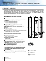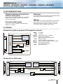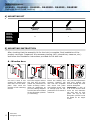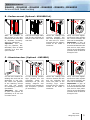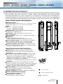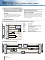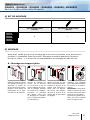
1
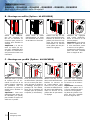
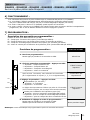
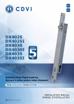
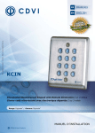
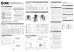
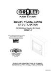
EN
FR
DX4025
DX4025I
DX4030
DX4030I
DX4035
DX4035I
Solenoid Bold Dead Locking
Serrure à pêne piston auto-bloquant
Range: Locking devices / Gamme: Verrouillage
INSTALLATION MANUAL
MANUEL D’INSTALLATION
Group Company
INSTALLATION MANUAL
DX4025 - DX4025I - DX4030 - DX4030I - DX4035 - DX4035I
Solenoid Bold Dead Locking
1] PRODUCT OVERVIEW
These bolt lock range are high-quality piston-driven self-locking deadlocks. These bolt locks
are available in “Fail secure” or “Fail safe” versions and with several distances for positioning European lock cylinders (not supplied). All bolt locks are fitted in standard with
an automatic locking system and door detector (Hall effect).
MECHANICAL SPECIFICATIONS:
Dimensions:
- Strike plate & face plate (HxWxD): 320 x 25 x 3mm.
- Lock body (HxWxD): 230 x 23 x 35mm
Backsets:
- 25mm = DX4025 and DX4025I,
- 30mm = DX4030 and DX4030I,
- 35mm = DX4035 and DX4035I.
Deadlocking: deadlocking mechanism totally
independent (Patented).
Saw proof: rotating cylindrical stainless steel bolt.
Anti-dust: stainless steel body totally sealed.
Robust:
- 3 MM face plates.
- Guiding bolt in stainless steel.
Euro Cylinder (not included). Use the M5x30 screw
to mount the euro profile cylinder.
ELECTRONIC SPECIFICATIONS:
Nominal power supply:
12Vdc (variation 11Vdc to 16Vdc).
Nominal consumption:
- 2.6A in-rush.
- 0.3A stand by.
Adjustable state: Fail secure or fail safe, power
to unlock (NC) or power to lock (NO).
Fail safe version: DX4025I, DX4030I and DX4035I.
Monitoring: maximum voltage 50mA at 30 VDC
that can be admitted by the OC.
Door Locked optical sensors
(Example: if “locking forced” or “unlocking forced”,
then re-locking will repeat 10 times, after the alarm)
Notice: normal unlock control resets the system
Door position by way of a magnet, placed on the
face plate, and by a Hall-effect sensor, inside
the lock body.
Interference reduction: this lock is activated
by a powerful electromagnet with double winding,
without current cutting.
TANCE
RESIS
HIGH NDALISM
TO VA
-20° C to +50°C
IP Rating 53
CE Certification
2
cdvi.com
cdvigroup.com
INSTALLATION MANUAL
DX4025 - DX4025I - DX4030 - DX4030I - DX4035 - DX4035I
Solenoid Bold Dead Locking
2] RECOMMANDATIONS
Distance between the bolt lock
and the strike plate.
For the best possible fit, allow for a maximum
distance of 3 to 5mm between the bolt lock
and the strike plate.
Recommended supply
There are 2 power supplies recommended:
ARD2/12 or AL500.
Mounting
To an optimum use, this range of solenoid bold dead
locking have to be mounted vertically.
Wiring
Allow cable to have the appropriate cross section
depending on the distance between the power
supply and the lock (0.6 to 1.6 mm). The bolt
lock comes with a 250MM cable length.
3] WIRING
Connection (with an optional CM magnetic contact)
Red
Input voltage
12VDC / 3A
Black
Black
Red
Yellow
Green
Gray
Cable
White
White
Brown
Brown
Magnetic
contact
Yellow
Blue
0V (GND)
+12 VDC
Push button with 0V (GND)
Output «door status»
(open collector 30VDC/50mA)
Output «Alarm»
(open collector 30VDC/50mA)
Input magnetic contact with 0V (GND)
Common Push button
and magnetic contact
Interlocking link
Green
+ 12VDC
Grey
Connection in SAS mode
Red
Red
Cable
Black
Input voltage
12VDC / 3A
Black
Brown
Yellow
Blue
Brown
PB
BP
Optional free access
Constant access
Yellow
Cable
Input voltage
12VDC / 3A
Blue
cdvi.com
cdvigroup.com
3
INSTALLATION MANUAL
DX4025 - DX4025I - DX4030 - DX4030I - DX4035 - DX4035I
Solenoid Bold Dead Locking
4] MOUNTING KIT
DX4025
DX4025I
DX4030
DX4030I
DX4035
DX4035I
Wood screw
(M3x16)
Screw
(M5x30)
8
1
5] MOUNTING INSTRUCTION
After checking that the assembly kit for the lock is complete, final installation of the
product can begin. Prepare all the necessary tooling (drill, screwdriver, measure, etc.)
and follow the installation instructions provided for the bolt lock.
A - Wooden door
1
2
Cut out a zone in the
support for holding the
lock case and its backplate. Then mark the
position of the retaining
screws.
4
cdvi.com
cdvigroup.com
Drill the support where
the lock and its backplates are positioned to
make screwing easier.
Allow for cableways as
per the cabling diagram
and drill the hole needed
for the European cylinder
(if necessary).
3
Insert the cabling and
connect. Position the
lock and the lockplate
and screw into place
with M3x16 screw. Leave enough play for adjustments to be made if
needs be.
4
Carry out final adjustments
and then tighten the
screws holding the lock
and its backplate.
Important: A gap of
3 to 5 mm at the most
must be left between
the lock and its lock
plate. The lug on the
European cylinder must
be fitted at an angle
of 45°.
INSTALLATION MANUAL
DX4025 - DX4025I - DX4030 - DX4030I - DX4035 - DX4035I
Solenoid Bold Dead Locking
B - Surface mount (Optional : KDX4000 kit)
1
Mark the position of
the centres on the door
frame and leaf, then drill
to facilitate screwing.
Allow for cableways.
Important: The housing kit (Optional, Ref:
KDX4000) must be fitted
vertically on a door that
opens inwards.
2
Pull out the supply cable
and fit the elements of
the kit on the door frame
and leaf.
3
Insert the cabling and
connect. Position the
lock and lockplate and
fix onto the kit. Leave
enough play for adjustments to be made if
needs be.
4
Carry out final adjustments and then tighten
the screws holding the
lock and its backplate.
Important: A gap of
3 to 5 mm at the most
must be left between the
lock and its lock plate.
The lug on the European
cylinder must be fitted at
an angle of 45°.
C - Aluminium door (Optional : KAF4000)
1
Cut out the surface for
holding the lock and its
backplate in the profile. Mark the position
of the retaining screws
and drill the profile
for facilitating screwing
operations.
Important: you need
to have the optional kit
(KAF4000) to fix the lock
in surface mount.
2
Fix the levelling position
lugs (screws are not
provided). Allow for
cableways as per the
cabling diagram and
drill the hole needed for
the European cylinder
(if necessary).
3
Insert the cabling and
connect. Position the lock
and the lockplate and
screw into place on the
levelling lugs. Leave
enough play for adjustments to be made if
needs be.
4
Carry out final adjustments and then tighten
the screws holding the
lock and its backplate.
Important: A gap of
3 to 5 mm at the most
must be left between the
lock and its lock plate.
The lug on the European
cylinder must be fitted at
an angle of 45°.
cdvi.com
cdvigroup.com
5
INSTALLATION MANUAL
DX4025 - DX4025I - DX4030 - DX4030I - DX4035 - DX4035I
Solenoid Bold Dead Locking
6] OPERATION:
1. The door is opened by the push-button control on 0V (GROUND).
2. Locking takes place automatically after the door has been detected: Either by the incorporated Hall effect
contact, or by a remote positioned Magnetic Contact (not included in our supply).
3. The “door status” output gives an 0V (GROUND) signal when the door is locked.
4. The “alarm” status gives an 0V (GROUND) signal, either when the door has remained open beyond
the programmed period of time, or if faults have been detected, or if the system has been forced.
7] PROGRAMMING:
Description of parameters that can be programmed:
(Use a 1.5MM width tool)
P1 – Delay time for the door staying open (5 seconds by default).
P2 – Alarm delay time if the door is not closed (5 seconds by default).
P3 – Locking delay time after the door has been shut (2.5 seconds by default).
P4 – Choice of contact for detecting the presence of the door (Hall Effect contact by default).
Programming procedure:
A – Entering the programming mode:
Press PRG for 3 to 4 seconds.
B – Selecting the parameter to be programmed - Press SEL:
- 1 push: P1 opening delay time
- 2 pushes: P2 alarm delay time
- 3 pushes: P3 locking delay time
- 4 pushes: P4 Contact selection
Your selection will be confirmed after about seven seconds
by the light flashing ( 1, 2, 3 or 4 flashes).
SEL
PRG
LIGHT
LIGHT STATUS
Permanently lit
1 flash
for each push
Confirmation given
by flashing
C- Modifying the parameter – Press PRG:
Delay times (P1, P2 and P3):
- 1 push: 2.5 seconds
- 2 pushes: 5 seconds … etc …
Delay time adjustments are made in steps of 2.5 seconds
(With a total number of 24 steps or a maximum delay time
of 60 seconds).
Contact for detecting the presence of the door (P4):
- 1 push: selecting the integrated Hall Effect contact.
- 2 pushes: selecting the remote Magnetic Contact.
- 3 pushes: selecting both the Hall Effect and Magnetic Contacts.
1 flash
for each push
D- Validating the adjustment and leaving
the programming mode:
- Press on PTRG for 3 to 4 seconds.
- Wait for the LED to switch on and then release the PRG button.
Switch off
when in contact
Note: The programming mode will be left automatically if no operations are carried out for 15 seconds.
6
cdvi.com
cdvigroup.com
MANUEL D’INSTALLATION
DX4025 - DX4025I - DX4030 - DX4030I - DX4035 - DX4035I
Serrure à pêne piston auto-bloquant
1] PRESENTATION DU PRODUIT
Ces produits sont des serrures à pêne piston auto-bloquants de haute qualité.
Elles sont disponibles en version «Emission» ou «Rupture» et avec plusieurs entraxes pour
le positionnement du cylindre européen (non fourni). Toutes ces serrures sont équipées en
série d’une détection automatique du verrouillage et de la présence de la porte (effet hall).
CARACTÉRISTIQUES MÉCANIQUES :
Encombrements :
- dimensions têtière & gâche (H x L x P) : 320 x 25 x 3 mm.
- dimensions coffre (H x L x P) : 230 x 23 x 35 mm.
Pêne :
- 25 mm = DX4025 et DX4025I,
- 30 mm = DX4030 et DX4030I,
- 35 mm = DX4035 et DX4035I.
Autobloquant : mécanisme autobloquant totalement
indépendant. (BREVET CDVI)
Anti-sciage : pêne cylindrique en inox tournant
dans son logement.
Anti-poussière : coffre en inox complètement fermé.
Robustesse :
- têtière d’une épaisseur de 3 mm.
- bloque massif en inox pour le guidage du pêne.
Serrure double action : sécurité positive ou négative,
déverrouillage à émission (NF) ou à rupture (NO)
de courant (sécurité des biens ou des personnes).
Cylindre européen (non fourni) : à monter à l’aide
de la vis cruciforme M5x30. Remarque : décondamnation
manuelle à l’entraxe de 25 mm.
CARACTÉRISTIQUES ÉLECTRONIQUES :
Signalisation : le courant maximum pouvant être
commuté est de 50 mA sous une tension maximum
de 30 V DC.
Détection du verrouillage de la porte : tout au long
de la course du pêne, par l’intermédiaire de capteurs
optiques (en cas de blocage du pêne : système de
«forçage de verrouillage» ou « forçage de déverrouillage »
répétitif sur 10 tentatives, puis alarme.).
Remarque : la commande d’ouverture permet de relancer
le système.
Détection de la porte par l’intermédiaire d’un aimant,
placé sur la gâche, et d’un capteur à effet Hall, positionné
dans le coffre de la serrure. Remarque : nous appelons
« gâche » la têtière positionnée sur la partie mobile.
Anti-parasitage : cette serrure est actionnée
par un électroaimant puissant à double bobinage,
sans découpage du courant.
Version «Rupture» : DX4025I, DX4030I et DX4035I.
Tension d’alimentation nominale :
12 V DC (limite 11 V DC à 16 V DC).
Consommation nominale :
2,6A à l’appel et 0,3A en maintien.
ance
Résist
Haute dalisme
au Van
-20° C à +50°C
Indice de protection IP53
Certification CE
cdvi.com
cdvigroup.com
7
MANUEL D’INSTALLATION
DX4025 - DX4025I - DX4030 - DX4030I - DX4035 - DX4035I
Serrure à pêne piston auto-bloquant
2] RAPPELS ET RECOMMANDATIONS
Distance entre la serrure et la tétière
Afin d’optimiser le montage, prévoyer de 3 à 5 mm
maximum de distance entre la gâche et la tétière.
Alimentation préconisée
Il existe 2 alimentations adaptées : ARD2/12 ou AL500.
Rappel de câblage
Montage
Pour un fonctionnement optimal, les électroserrures DX4025, DX4025I, DX4030, DX4030I,
DX4035, DX4035I doivent être installée
à la verticale.
Prévoir un raccordement avec une section de câble
appropriée à la distance qui sépare l’alimentation
de la serrure (0,6 à 1,5 mm). Tous les fils non
utilisés doivent être isolés. La longueur du câble
fourni est de 250 mm.
3] RACCORDEMENTS
Raccordement (avec un contact magnétique CM en option)
Rouge
Alimentation
12 V DC / 3A
Noir
Noir
Rouge
Jaune
Vert
Gris
Câble
Blanc
Blanc
Marron
Contact
magnétique
(CM)
Jaune
Vert
Marron
Bleu
0V (MASSE)
+12 V DC
Commande BP par le 0V (MASSE)
Sortie « Etat Porte »
(collecteur ouvert 30 V DC / 50 mA)
Sortie « Alarme »
(collecteur ouvert 30 V DC / 50 mA)
Entrée contact magnétique
par le 0V (MASSE)
Commun BP et contact magnétique
Liaison pour mode SAS
+ 12 V DC
Gris
Raccordement en mode SAS
Rouge
Rouge
Câble
Noir
Noir
Marron
Marron
BP
Jaune
Bleu
8
Alimentation
12 V DC / 3A
BP
Option ouverture libre
Ouverture constante
cdvi.com
cdvigroup.com
Jaune
Bleu
Câble
Alimentation
12 V DC / 3A
MANUEL D’INSTALLATION
DX4025 - DX4025I - DX4030 - DX4030I - DX4035 - DX4035I
Serrure à pêne piston auto-bloquant
4] KIT DE MONTAGE
Vis bois à tête fraisée
(M3x16)
DX4025
DX4025I
DX4030
DX4030I
DX4035
DX4035I
Vis cruciforme à tête fraisée
(M5x30)
8
1
5] MONTAGE
Après avoir vérifié que le kit de montage de la serrure soit complet, vous allez pouvoir
procéder à l’installation finale du produit. Réunissez le matériel approprié (Perceuse,
tournevis, mètre,...) et suivez les recommandations de montage de cette serrure.
A - Montage sur support plein
1
Découpez dans le support
une partie creuse qui va
accueillir le coffre de
la serrure et ses contreplaques. Puis faites les
marquages de la position des vis de fixation.
2
Percez le support au
niveau de la fixation
de la serrure et de sa
contre-plaque pour faciliter le vissage. Suivant
le schéma de câblage,
prévoyez le passage
des câbles, ainsi que
le perçage de l’espace
pour le cylindre européen
(si nécessaire).
3
Passez vos fils, et réalisez vos branchements.
Insérez la serrure et sa
gâche puis fixez-les à
l’aide des vis M3x16.
Ne serrez pas définitivement la serrure et sa
gâche afin de permettre
le réglage.
4
Finalisez les réglages
puis vissez définitivement
la serrure et sa contreplaque.
Important : vous devez
laisser un espace de 3 mm
à 5 mm maximum entre
la serrure et sa gâche.
La patte du cylindre européen doit être installée
avec un angle de 45°.
cdvi.com
cdvigroup.com
9
MANUEL D’INSTALLATION
DX4025 - DX4025I - DX4030 - DX4030I - DX4035 - DX4035I
Serrure à pêne piston auto-bloquant
B - Montage en saillie (Option : kit KDX4000)
1
2
Faites
les
marquages des entraxes du
kit sur le dormant et
l’ouvrant puis percez la
surface pour faciliter le
vissage.
Important : le kit de
mise en saillie (En option, Réf : KDX4000) doit
se poser en vertical sur
une porte s’ouvrant vers
l’intérieur.
3
Faites sortir le câble
d’alimentation et fixez
les éléments du kit sur
le dormant et l’ouvrant.
4
Passez vos fils, et réalisez vos branchements.
Insérez la serrure et sa
gâche puis fixez-les sur
le kit. Ne serrez pas définitivement la serrure
et sa gâche afin de permettre le réglage.
Finalisez les réglages
puis vissez définitivement la serrure et sa
contre-plaque.
Important : vous devez
laisser un espace de 3 à
5 mm maximum entre
la serrure et sa gâche.
La patte du cylindre européen doit être installée
avec un angle de 45°.
C - Montage sur profilé (Option : kit KAF4000)
1
2
Découpez dans le profilé
la surface qui va accueillir la serrure et sa
contre-plaque. Marquez
les positions des vis
de fixation et percez le
profilé pour facilitez le
vissage.
Important : Vous avez
impérativement besoin du
kit KAF4000 (en option)
pour installer la serrure en
saillie sur un profilé.
10
cdvi.com
cdvigroup.com
Fixez les pattes de mise
en affleurement (attention
les vis ne sont pas fournies).Suivant le schéma
de câblage, prévoyez le
passage de vos câbles,
ainsi que le perçage de
l’espace pour le cylindre
européen (si nécessaire).
3
Passez vos fils, et réalisez vos branchements.
Insérez la serrure et
sa contre-plaque puis
fixez-les sur les pattes
de mise en affleurement.
Ne serrez pas définitivement la serrure et sa
gâche afin de permettre
le réglage.
4
Finalisez les réglages
puis vissez définitivement
la serrure et sa contreplaque.
Important : vous devez
laisser un espace de 3
à 5 mm maximum entre
la serrure et sa gâche.
La patte du cylindre européen doit être installée
avec un angle de 45°.
MANUEL D’INSTALLATION
DX4025 - DX4025I - DX4030 - DX4030I - DX4035 - DX4035I
Serrure à pêne piston auto-bloquant
6] FONCTIONNEMENT :
1. La commande d’ouverture de porte s’effectue par la commande BP portée au 0V (MASSE).
2. Le verrouillage s’effectue automatiquement après détection du contact de présence porte :
soit par le contact Effet Hall intégré, soit par un Contact Magnétique déporté (non fourni).
3. La sortie « état porte » donne un 0V (MASSE) quand la porte est verrouillée.
4. La sortie « alarme » donne un 0V (MASSE) soit quand la porte reste ouverte au-delà de la temporisation
programmée, soit en cas de défauts détectés ou soit en forçage du système.
7] PROGRAMMATION :
Description des paramètres programmables :
(Utiliser un outil d’une taille inférieur à 1,5 mm)
P1 - Tempo pour l’ouverture de la porte (5 secondes par défaut).
P2 - Tempo d’alarme pour non fermeture de la porte (5 secondes par défaut).
P3 - Tempo de verrouillage après fermeture de la porte (2,5 secondes par défaut).
P4 - Choix du contact pour la détection de la présence porte (contact Effet Hall par défaut).
Procédure de programmation :
A - Entrée en programmation :
Restez appuyer pendant 3~4 secondes sur PRG.
B - Choix du paramètre programmable – Appuyer sur SEL :
- 1 impulsion : Tempo d’ouverture P1
- 2 impulsions : Tempo d’alarme P2
- 3 impulsions : Tempo de verrouillage P3
- 4 impulsions : Choix du contact P4
Après environ 7 secondes, votre sélection sera confirmée
par le clignotement du voyant ( 1, 2, 3 ou 4 clignotements).
SEL
PRG
VOYANT
ETAT DU VOYANT
Allumé fixe
1 flash à chaque
impulsion
Confirmation par
clignotement
C- Réglage du paramètre – Appuyer sur PRG :
Temporisations (P1, P2 et P3) :
- 1 impulsion : 2.5 secondes
- 2 impulsions : 5 secondes … etc …
Le réglage des temporisations s’effectue par palier de 2.5 secondes
(avec un total de 24 paliers, soit une tempo de 60 secondes maximum).
1 flash à chaque
impulsion
Contact pour la détection de la présence porte (P4) :
- 1 impulsion : prise en compte du contact Effet Hall intégré.
- 2 impulsions : prise en compte du Contact Magnétique déporté.
- 3 impulsions : prise en compte des deux contacts EH et CM.
D- Validation du réglage et sortie de programmation :
Restez appuyer pendant 3~4 secondes sur PRG.
Attendre que la LED s’allume et relâchez PRG.
Eteint pendant l’appui
Remarque : sortie automatique de programmation après 15 secondes sans action.
cdvi.com
cdvigroup.com
11
Reference : G0301FR0260V04
Extranet : EXE-CDVI_IM DX4025-30-35 CMYK A5 EN-FR 02
CDVI (Headquarters/Siège social)
FRANCE
Phone: +33 (0)1 48 91 01 02
Fax: +33 (0)1 48 91 21 21
CDVI
SWITZERLAND
Phone: +41 (0)21 882 18 41
Fax: +41 (0)21 882 18 42
CDVI
MAROC
Phone: +212 5 22 48 09 40
Fax: +212 5 22 48 34 69
CDVI
AMERICAS
Phone: +1 (450) 682 7945
Fax: +1 (450) 682 9590
CDVI
CHINA
Phone: +86 (0)10 87664065
Fax: +86 (0)10 87664165
CDVI
SWEDEN
Phone: +46 (0)31 760 19 30
Fax: +46 (0)31 748 09 30
CDVI
BENELUX
Phone: +32 (0) 56 62 02 50
Fax: +32 (0) 56 62 02 55
CDVI
IBÉRICA
Phone: +34 935 390 966
Fax: +34 935 390 970
CDVI
UK
Phone: +44 (0)1628 531300
Fax: +44 (0)1628 531003
CDVI
TAIWAN
Phone: (0)42471 2188
Fax: (0)42471 2131
CDVI
ITALIA
Phone: +39 0331 97 38 08
Fax: +39 0331 97 39 70
DIGIT
FRANCE
Phone: +33 (0)1 41 71 06 85
Fax: +33 (0)1 41 71 06 86
cdvigroup.com
Toutes les indications mentionnées sur le présent document (photos, dessins, caractéristiques et côtes) sont susceptibles
de modifications sans notification préalable.
All the specifications on this document (photos, drawing, features and dimensions) could be changed without prior notice.
Manufacturing Access Control since 1985
LA GÂCHE ÉLECTRIQUE
FRANCE
Phone: +33 (0)3 88 77 32 82
Fax: +33 (0)3 88 77 85 02