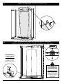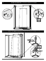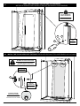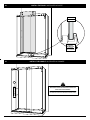
1
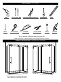
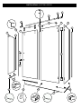
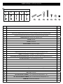
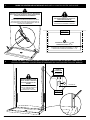
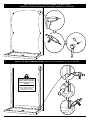
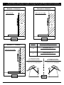
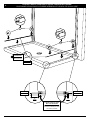
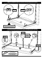
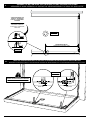
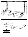
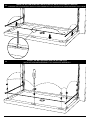
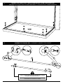
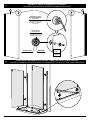
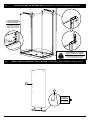
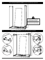
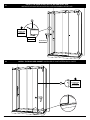
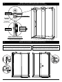
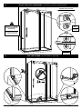
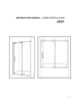
INSTRUCTION MANUAL - GUIDE D’INSTALLATION
10 / 2013
K007
2 PEOPLE REQUIRED
2 PERSONNES REQUIS
Please keep this manual and product code number for future reference
and for ordering replacement parts if necessary.
Veuillez conserver ce manuel et le code de produit pour des références futures,
et au besoin, la commande de pièces de rechange.
GENERAL INSTRUCTIONS
•
Read this manual carefully and completely
En
INSTRUCTIONS GÉNÉRALES
•
before proceeding.
•
It is recommended that you wear safety
•
If your shower door is to be installed over
ceramic tiles, the tiles should lay com-
•
Silicone should be used to seal the gap
where the ceramic tiles meet the fixed panel.
INSTALLATION SUR LES TUILES EN CÉRAMIQUE
•
cette dernière.
•
Le calfeutrage doit être appliqué sur le côté extérieur
de la douche où le panneau fixe rencontre la bordure
en céramique.
Caulking: no sealant is required inside the
shower, unless otherwise stated.
•
Si votre porte de douche doit être installée sur une bordure
en céramique, le jambage doit reposer complètement sur
NOTICE
•
Il est recommandé de porter des lunettes de sécurité en
tout temps lors de l’installation.
pletely under the wall jamb.
•
Fr
d’installation avant de procéder.
glasses at all times during the installation.
INSTALLATION OVER CERAMIC TILES
Lire attentivement et complètement le manuel
Some models are equipped with clear
sealing gaskets.
NOTE
•
Calfeutrage: aucun scellant n’est nécessaire à l’intérieur
de la douche.
•
Certains modèles sont dotés de joints d’étanchéité clairs.
CARE FOR YOUR SHOWER DOOR
•
•
Never use scouring powder pads or sharp
L’ENTRETIEN DE VOTRE DOUCHE
instruments on metal pieces or glass pan-
•
Ne jamais utiliser de poudre ou de tampon à récurer, ni
els. An occasional wiping down with a mild
d’instrument tranchant sur les parties en métal ou en verre.
soap diluted in water is all that is needed
De temps à autre, il suffit de nettoyer la porte avec une
to keep the panels and aluminum parts
solution d’eau et un détergent doux pour conserver l’aspect
looking new.
neuf des panneaux de verre et du cadre en aluminium.
We recommend wiping the glass panels
with a squeegee after each use.
•
Nous recommandons de passer une raclette de douche
sur les panneaux de verre après chaque utilisation.
Product specifications are subject to change without notice • Des changements peuvent être apportés au produit sans préavis.
TOOLS REQUIRED / OUTILS REQUIS
*
DRILL
1/4" & 1/8" DRILL BITS
PERCEUSE
MÈCHE 1/4" & 1/8"
LONG NOSE LOCKING PLIERS (X2)
PINCE SERRE ÉTAU (X2)
SCREWDRIVER
LEVEL
TOURNEVIS
NIVEAU
PENCIL
TAPE MEASURE
HACKSAW
CUTTING PLIERS
MALLET
SILICONE
CRAYON
RUBAN À MESURER
SCIE À MÉTAUX
PINCE COUPANTE
MAILLET
SCELLANT
* Use a ¼" drill bit for ceramic when drilling into ceramic tiles
* Utiliser une mèche de ¼" destiné à céramique lors du perçage des tuiles en céramique.
possible
configurations / configurations
possibles
possible
configurations
configurations
possibles
*
* This configuration is illustrated in this manual.
* Cette configuration est illustrée dans ce manuel.
PARTS LISTING / LISTE DES PIÈCES
3
6
2
4
8
7
14
10
12
16
1
9
11
1
5
13
18
17
15
19
18
17
PARTS LISTING / LISTE DES PIÈCES
12
HANDLE OPTIONS / SÉLECTION DES POIGNÉES
A
B
C
D
E
20
21
22
23
24
25
26
ITEM
PARTS AND HARDWARE / PIÈCES ET QUINCAILLERIE
QTY
1
WALL JAMB / JAMBAGE
2
2
RUNNING RAIL / BARRE DE ROULEMENT
1
3
Return panel BRACKET on the fixed panel side with GLASS MOUNT /
SUPPORT du panneau de retour sur le côté du panneau fixe avec FIXATION DE VERRE
1
4
RETURN PANEL BRACKET ON THE DOOR SIDE WITH BUILT-IN STOPPER /
SUPPORT DU PANNEAU DE RETOUR DU CÔTÉ DE LA PORTE AVEC BUTOIR INTÉGRÉ
1
5
corner glass clip / SUPPORT de verre du coin
2
6
STOPPER / BUTOIR
1
7
ROLLER / ROULETTE
4
8
GLASS FASTENER / FIXATION DE VERRE
2
9
DOOR PANEL / PANNEAU DE PORTE
1
10
FIXED PANEL / PANNEAU FIXE
1
11
RETURN PANEL / PANNEAU DE RETOUR
1
12
RETURN PANEL WITH THE GLASS CORNER CLIP HOLES
PANNEAU DE RETOUR AVEC LES TROUS POUR LE SUPPORT DE VERRE DU COIN
1
13
HANDLE ( see chart above ) / POIGNÉE ( voir le tableau ci-dessus )
1
14
DOOR GASKET ON THE RETURN PANEL SIDE / JOINT DE LA PORTE DU CÔTÉ DU PANNEAU DE RETOUR
1
15
BOTTOM DOOR GASKET / JOINT INFÉRIEUR DE LA PORTE
1
16
DOOR SIDE GASKET / JOINT LATÉRAL DE LA PORTE
1
17
THRESHOLD / SEUIL DE RÉTENTION
3
18
BOTTOM GLASS CLIP / SUPPORT DE VERRE INFéRIEUR
5
19
BOTTOM GUIDE / GUIDE INFéRIEUR
1
20
CLEAR SETTING BLOCK (⅛″) / BLOC NIVEAU TRANSPARENT (⅛″)
4
21
CLEAR SETTING BLOCK (1/ 32″) / BLOC NIVEAU TRANSPARENT (1/ 32″)
4
22
WALL PLUG / CHEVILLE
6
23
self-drilling WALL SCREW #8 - 1 ¼" / VIS MURAL auto-perçante #8 - 1 ¼"
6
24
self drilling PANHEAD SCREWS #8 - ⅜" / VIS À TÊTE PAN auto-perçante #8 - ⅜"
6
25
SCREW CAP / CAPUCHON COUVRE-VIS
6
26
BACK SCREW CAP / L’ARRIÈRE DU CAPUCHON COUVRE-VIS
6
1
mark the centerline on the base / marquer la ligne du centre sur la base
THE INSTALLATION SHOWN IS BASED ON PLUMB FINISHED
WALLS AND A LEVELLED BASE. IF THESE CONDITIONS ARE
NOT MET, PLEASE ADJUST ACCORDINGLY.
L’INSTALLATION ILLUSTRÉE EST BASÉE SUR DES MURS
FINIS D’APLOMB ET UNE BASE DE DOUCHE NIVELÉE. SI
CES CONDITIONS NE SONT PAS PRÉSENTÉES, VEUILLEZ
AJUSTER EN CONSÉQUENCE.
the centerline must fall within the
range indicated below.
la ligne du centre doit se situer entre
les distances indiquées ci-dessous.
TOP VIEW
VUE DU HAUT
running rail length + 1 ⅞″ and
running rail length + 3 ⅞″
longueur de la barre de roulement + 1 ⅞″ et
longueur de la barre de roulement + 3 ⅞″
2
place the wall jambs on the wall and mark the positions of the wall jamb holes
placer les jambages contre le mur et marquer les positions des trous du jambage
Interior
shower side
INTÉRIEUR
DE LA DOUCHE
the holes located on the
side of the wall jamb must
face the interior of the
shower.
les trous situés sur le
côté du jambage devraient
être orientés vers
l’intérieur de la douche.
6
1
= =
CENTERLINE
LIGNE CENTRALE
TOP VIEW
VUE DU HAUT
3
drill the holes, apply silicone & inSert the wall plugs
percer les trous, appliquer du silicone & insÉrer les chevilles
22
4
install the wall jambs as shown / installer les jambages tels qu’illustrés
the holes located on the
side of the wall jamb must
face the interior of the
shower.
23
les trous situés sur le
côté du jambage devraient
être orientés vers
l’intérieur de la douche.
7
5
USE the level to verify if wall is plumb. calculate and cut the threshold length accordingly
utiliser le niveau pour vérifier si le mur est d’aplomb. calculer et couper le seuil en conséquence
Scenario 1 / Scénario 1
Scenario 2 / Scénario 2
0º
WALL IS PLUMB
WALL IS OUT OF PLUMB
MUR EST D’APLOMB
MUR EST HORS D’APLOMB
wall
MUR
wall
MUR
base
base
SIDE VIEW
SIDE VIEW
VUE LATÉRALE
VUE LATÉRALE
Scenario
Scénario
Scenario 3 / Scénario 3
Threshold length calculation
Formule pour la longueur de seuil
return panel width +
1&2
WALL IS OUT OF PLUMB
⅜"
largeur du panneau de retour +
⅜"
MUR EST HORS D’APLOMB
return panel width +
3
wall
MUR
largeur du panneau de retour +
SIDE VIEW
VUE LATÉRALE
cut threshold as shown
for the right return panel
couper tel qu’illustré pour le panneau
de retour sur le côté gauche
couper tel qu’illustré pour le panneau
de retour sur le côté droite
17
90º
90º
45º
45º
AFTER
APRÈS
8
⅞"
cut threshold as shown
for the left return panel
17
base
⅞"
6
position the bottom glass clipS and threshold as shown
positionner leS supportS de verre inférieurS et le seuil tel qu’illustré
18
18
Interior
shower side
17
INTÉRIEUR
DE LA DOUCHE
SIDE VIEW
VUE LATÉRALE
TOP VIEW
VUE DU HAUT
TOP VIEW
VUE DU HAUT
¼"
6mm
3"
76mm
ALIGN BOTTOM CLIP HOLES
WITH THE CENTERLINE
ALIGNER LES TROUS DES
SUPPORTS INFéRIEURS AVEC
LA LIGNE DU CENTRE
9
7
mark the threshold as well as the hole & location for each bottom clip
marquer la position du seuil et les positions des supports de verre inférieurs ainsi que leurs trous
TOP VIEW
VUE DU HAUT
TOP VIEW
VUE DU HAUT
remove the gaskets before marking.
enlever les joints avant de marquer.
place the THRESHOLD, bottom guide, AND bottom glass clip onto the base
placer le SEUIL, guide INFÉRIEUR, ET le support de verre inférieur sur la base
8
SIDE VIEW
VUE LATÉRALE
Interior
shower side
INTÉRIEUR
DE LA DOUCHE
TOP VIEW
VUE DU HAUT
19
17
18
TOP VIEW
VUE DU HAUT
TRIM THE EDGE OF THE THRESHOLD
AT 45º IF NECESSARY.
COUPER LE CÔTé DU SEUIL
À 45º SI NÉCESSAIRE.
10
9
arrange the bottom guide, bottom glass clip and threshold as shown
arranger le guide inférieur, le support de verre inférieur et le seuil tel qu’illustré
the bottom guide can
hang off the base as
long as it can be well
fastened.
le guide inférieur peut
dépasser la base en
autant qu’il puisse être
bien fixé.
TOP VIEW
VUE DU HAUT
Fixed panel width
Largeur du panneau fixe
SIDE VIEW
VUE DU CÔTÉ
10
mark the threshold as well as the hole & location for the bottom clip & bottom guide
marquer la position du seuil et les positions du support de verre inférieur et le guide inférieur ainsi que leurs trous
TOP VIEW
VUE DU HAUT
3"
76mm
remove the gaskets before marking.
enlever les joints avant de marquer.
¼" min.
¼" min.
6mm min.
6mm min.
11
11
remove the bottom guide, bottom clips and the thresholds
enlever le guide inférieur, les supports de verre inférieurs et les seuils
12
DRILL the marked thresholds / PERCER les seuils marqués
USE A BLOCK OF WOOD AS A
WORKING SURFACE IN ORDER TO
DRILL THE THRESHOLD HOLES.
UTILISER un bloc DE BOIS COMME
SURFACE DE TRAVAIL POUR PERCER
LE SEUIL DE RéTENTION.
12
13
14
mark the bottom guide and the bottom clip hole locations on the base
marquer les positions des trous du guide inférieur et des supports de verre inférieurs sur la base
install the bottom guide and the bottom clips
installer le guide inférieur et les supports inférieurs
13
15
reinsert the gaskets into the bottom guide and the bottom glass clips
réinsérer les joints dans le guide inférieur et les supports de verre inférieurs
16
assemble the running rail / assembler la barre de roulement
4
2
3
6
SLIGHTLY TIGHTEN THE SCREW ON THE BRACKETS ONLY, IN ORDER
TO PREVENT THEM FROM SLIPPING OFF.
SERRER LÉGÈREMENT LES VIS SUR LES SUPPORTS SEULEMENT,
POUR ÉVITER QU’ILS GLISSENT DE LA BARRE.
14
secure the two return panels glass mounts
sécuriser les fixation de verre des panneaux de retour
17
11
12
UNSCREW THE GLASS
MOUNT AND SEPARATE
BOTH PARTS.
DÉVISSER LA FIXATION
DE VERRE ET SÉPARER
LES 2 PIÈCES.
sits at the top
of the glass
reposer sur le cÔté
supérieur du verre
glass hole
trou du verre
18
washer
rondelle
INTERIOR
VIEW
VUE DE
L’INTÉRIEUR
place the return panels into the wall jambs and the bottom glass clips
placer les panneaux de retour dans les jambages et les supports de verre inférieurs
15
19
Level and clamp the return panels / niveler et fixer les panneaux de retour
add clear setting
blocks into the bottom
clip if necessary.
ajouter des blocs À
niveau au support de
verre si nécessaire.
COVER THE TEETH OF THE PLIERS
TO AVOID SCRATCHING THE METAL.
COUVRIR LES DENTS DE LA PINCE
POUR NE PAS RAYER LE MÉTAL.
20
INSTALL THE bottom gasket ONTO THE DOOR / INSTALLER LE joint inférieur SUR LA PORTE
9
15
Interior
shower side
INTÉRIEUR
DE LA DOUCHE
16
21
place the door inside the shower / placer la porte dans la douche
PLACE THE DOOR ON A protective
SURFACE TO PREVENT SCRATCHING THE
SHOWER BASE and glass panel.
PlaceR la porte sur UNE SURFACE
protectrice pour éviter de rayer la
base de douche et le panneau de verre.
22
install the RUNNING RAIL / installer la barre DE ROULEMENT
17
23
install THE FIXED PANEL / Installer le PANNEAU FIXE
24
level the running rail and adjust the fixed panel if necessary
niveler la barre de roulement et ajuster le panneau fixe si nécessaire
FRONT VIEW
VUE DE FACE
add clear setting
blocks into the bottom
clip and bottom guide
if necessary.
ajouter des blocs
À niveau au support
de verre et au guide
inférieur si nécessaire.
ensure that the fixed
panel is pushed against
the return panel and is
flush. adjust the glass
fasteners if necessary.
S’assurer que le panneau
fixe est poussé contre
le panneau de retour et
est d’aplomb. ajuster les
fixations de verre
si nécessaire.
18
25
secure the running rail / sécuriser la barre de roulement
INTERIOR
VIEW
VUE DE
L’INTÉRIEUR
26
install the corner glass clips / installer les supports de verre du coin
INTERIOR
VIEW
VUE DE
L’INTÉRIEUR
5
19
level the fixed panel then secure the expanders
mettre le panneau fixe à niveau et ensuite sécuriser les extenseurs
27
ADJUST THE RETURN
PANEL IF NECESSARY.
AJUSTER LE PANNEAU DE
RETOUR SI NÉCESSAIRE.
25
24
28
INTERIOR
VIEW
VUE DE
L’INTÉRIEUR
install THE top rollers onto the door / installer les roulettes supérieures sur la porte
ENSURE THAT THE GASKETS ARE
BETWEEN THE GLASS ON EACH SIDE.
aSSURER QUE LES JOINTS SONT
ENTRE LE VERRE DE CHAQUE CÔTÉ.
SIDE VIEW
VUE DE CÔTÉ
7
Interior
shower side
INTÉRIEUR
DE LA DOUCHE
eccentric WASHER
INSTALLED AS SHOWN
RONDELLE excentrique
INSTALLÉE TEL QU’ILLUSTRÉE
20
26
29
install the door / installer la porte
SIDE VIEW
VUE LATÉRALE
Interior
shower side
INTÉRIEUR
DE LA DOUCHE
30
INSTALL THE HANDLE / INSTALLER LA POIGNéE
HANDLE / POIGNÉE
13
SEE INSTRUCTIONS ENCLOSED WITH HANDLE FOR
INSTALLATION PROCEDURES.
Voir les instructions qui sont enfermés avec la
poignée POUR les procédures d’installation.
21
31
install the DOOR gasket ON THE RETURN PANEL SIDE
installer le joint de la porte DU CÔTÉ DU PANNEAU DE RETOUR
14
Interior
shower side
INTÉRIEUR
DE LA DOUCHE
TOP VIEW
VUE DU HAUT
WOOD BLOCK
BLOC DE BOIS
32
install THE DOOR SIDE gasket / installer le joint latéral DE LA PORTE
16
22
Interior
shower side
INTÉRIEUR
DE LA DOUCHE
install THE bottom rollers onto the door
installer les roulettes inférieures sur la porte
33
FRONT VIEW
VUE DE FACE
eccentric
washer
glass hole
trou du verre
rondelle
excentrique
SIDE VIEW
VUE DE CÔTÉ
Interior
shower side
INTÉRIEUR
DE LA DOUCHE
ensure that the bottom roller is
pushed up against the rolling rail.
assurer que la roulette inférieure
touche le rail de roulement.
34
secure the stoppers / sécuriser les butoirs
POSITION THE STOPPER SO THAT IT LIES FLUSH AGAINST THE ROLLER WHEN THE DOOR IS IN
THE CLOSED POSITION AND THE ADHESIVE DOOR GASKET IS TOUCHING THE return panel.
POSITION THE STOPPER SO THAT IT LIES FLUSH AGAINST THE ROLLER AND
PREVENTS THE HANDLE FROM HITTING THE FIXED PANEL WHEN THE DOOR IS OPEN.
Positionner lE BUTOIR de sorte QU’IL BUTE contre la roulette LORSQUE LA PORTE
EST DANS LA POSITION FERMÉE ET LE JOINT ADHÉSIF touche le panneau de retour.
Positionner lE BUTOIR de sorte QU’IL BUTE CONTRE la roulette et empêche
la poignée de frapper le panneau fixe LORSQUE LA PORTE EST OUVERTE.
23
35
adjust the door if necessary / ajuster la porte si nécessaire
UNSCREW LIGHTLY & rotate
DÉVISSER LÉGÈREMENT et tourner
INTERIOR
VIEW
ENSURE THAT THE DOOR
LIES FLUSH AGAINST THE
return panel.
VUE DE
L’INTÉRIEUR
aSSURER QUE LA PORTE
SOIT D’APLOMB CONTRE
LE panneau de retour.
washer
rondelle
front VIEW
VUE De face
36
seal the shower / calfeutrer la douche
HOURS
HEURES
24