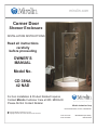
1
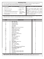
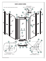
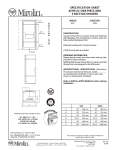
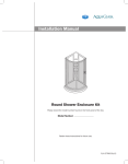
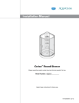
mirolin.com
Corner Door
Shower Enclosure
INSTALLATION INSTRUCTIONS
Read all instructions
carefully
before proceeding
OWNER’S
MANUAL
Model No.
CD 38NA
42 NAD
For ALL Installation & Product Related Inquires
Contact Mirolin Customer Care at 800. MIROLIN
Please Do Not Contact Retailer
baths for this generation and the next
Mirolin Industries Corp
60 Shorncliffe Road, Toronto, ON M8Z 5K1
Copyright Mirolin Industries corp., 2011
Copyright includes all content included in this document
T 416 231 5790
F 416 231 0929
800 MIROLIN (647 6546)
800 463 2236
mirolin.com
Thank you and congratulations on the purchase of your Mirolin bath and/or shower product.
Please read and follow the installation guide for detailed step by step instructions on how to install and
care for your Mirolin product for years of continued performance and enjoyment.
Should you require assistance with product assembly and/or installation, have any technical questions or
concerns regarding your Mirolin product, please contact Mirolin Customer Care at 800.MIROLIN(647-6546)
and speak to one of our highly trained, professional customer care representatives.
Live Customer Care is available 8am to 6pm EST Monday to Friday
Call Mirolin Customer Care at 800.MIROLIN(647-6546)
Email Mirolin Customer Care at [email protected]
mirolin.com
Your User-Friendly On-line Mirolin Resource Centre
Downloads
Downloadable product specifications and installation instructions for all products
Maintenance & Warranty
Detailed product maintenance and warranty information at your fingertips
Product Information
Detailed product information including product features, options information, list pricing and lifestyle imagery
IMPORTANT
Please Read Complete Instructions Carefully Before Proceeding with Installation
For ALL Installation and Product Related Inquires
Contact Mirolin Customer Care at 800.MIROLIN
Please Do Not Contact Retailer
2
INTRODUCTION
This Corner Shower Enclosure Installation Instruction Manual has been designed to make installation as
easy as possible. Please read this booklet completely prior to installing your unit.
BASIC TOOLS REQUIRED
"
"
"
"
"
"
Electric drill
Drill bit 1/8” (3.4 mm)
Phillips screw driver
Level (horizontal and vertical bubbles)
Measuring tape with metric markings
Framing square
"
"
"
"
GENERAL CUSTOMER INFORMATION
9/16” wrench
Knife / Cutter
Pencil
Clear mildew
resistant silicone
caulking
Never use scouring powder, pads or sharp
instruments on the metal framing or glass
panels.
An occasional cleaning with a mild liquid
detergent or cleaner such as a window
cleaner is all that is required to keep your
enclosure looking like new.
Begin familiarizing yourself with all the components using the detailed (exploded) diagram on page 4 and the
descriptions below. Use this as a checklist against all parts included in the package.
ITEM
DESCRIPTION
QTY
Wall Jamb Left
1
1
Wall Jamb Right
1A
1
Fixed Panel Left
2
1
Fixed Panel Right
2A
1
Top Header
3
1
Bottom
Sill
4
1
Hinge Assembly (top and bottom)
5
2
Hinge
2
5A
Rubber Washer Outside
2
5B
Plastic Spacer Insert
2
5C
Rubber Washer Inside
2
5D
Inside Cover
2
5E
Machine Set Screw
2
5F
Door Panel Threaded Stud
4
5G
Steel Washer
4
5H
Steel Nut
4
5J
#8 x 1 1/2” Long Screw
6
2
Handle Assembly
7
1
Long
Handle
7A
1
Small Male Handle
7B
1
Spacer
7C
1
Door Panel
8
1
Long Vertical Gasket Seal
9
1
Magnetic strip
10
2
#8 x 1” Long Screw
11
6
#8 x 1/2” Long Screw
12
6
Screw Cap
13
6
Bolt / Nut Assembly (Top and Bottom)
14
4
Sill / Header Threaded Stud
14A
4
Plastic Spacer Insert
14B
4
Plastic Washer
14C
4
Steel Nut
14D
4
Short
Bottom
Sweep
Gasket
Seal
15
1
Long Bottom Sweep Gasket Seal
16
1
Plastic Plug
17
6
Please record the date code from the carton. Date Code: ____________________
Please specify the part number, glass pattern and colour of the door when ordering replacement parts.
3
EXPLODED VIEW
DETAIL VIEW I
BOLT / NUT ASSEMBLY - ITEM 14
NOTE: RIGHT HAND DOOR SWING SHOWN
14D
1
14A
2-2A
Inside
2
2A
14
14C
8
1A
Outside
11
17
14B
3
10
5
9
13
12
7
5D
5A
15
8
16
5
5J
6
Outside
7C
7B
4
5H
5G
5F
Inside
7A
Inside
5E
5C
DETAIL VIEW III
HANDLE ASSEMBLY - ITEM 7
Outside
8
5B
DETAIL VIEW II
HINGE ASSEMBLY-ITEM 5
4
STEP 1: Remove the lid from box.
Remove packaging and inspect all door components
thoroughly before installation. Check to ensure all
the hardware parts are in the package.
STEP 2: Measure 1/4’’ (6 mm) from the outside edge
of the threshold and make a pencil mark. This is a
location of the Wall Jamb (1). Repeat this step on the
other side wall.
½’’
STEP 3: Align the Wall Jamb (1) with the pencil mark
and drill the bottom hole into the shower wall using
1/8” drill bit. Note: Drill the hole through the predrilled hole in the wall jamb.
STEP 4: Using a Long Screw # 8 x1” (11) provided,
fasten the Wall Jamb (1) to the wall.
STEP 5: Place a level against the Wall Jamb and
make sure the Wall Jamb is plumb. Mark the middle
and top hole drill locations.
STEP 6: Drill holes using a 1/8” drill bit and fasten the
Wall Jamb (1) using # 8 x 1” Long Screws (11).
5
STEP 7: Repeat steps 3 - 6 on the other side.
STEP 8: Insert the Left Hand Fixed Panel (2) into the
Wall Jamb (1) as shown.
STEP 9: Drill holes into the Fixed Panel (2) at the 3
hole locations using a 1/8” drill bit. Fasten the Fixed
Panel (2) to the Wall Jamb (1) using the # 8 x ½’’ Long
Screws provided (12).
STEP 10: Insert Right Hand Fixed Panel (2A) into the
Wall Jamb Right (1A). Repeat steps 8 - 9 on the right
side.
Note: Step 11 and Step 12 determine the door swing. The two door hinge studs on the sill determine the
hinge side and swing of the door, Left or Right.
STEP 11: Place the Bottom Sill (4) across the
threshold and insert the Threaded Stud (14A) into the
hole in the Left Hand Fixed Panel (2).
STEP 12: Insert the Threaded Stud(14A) through the
hole in the Right Hand Fixed Panel (2A).
RIGHT HAND
DOOR SWING SHOWN
Door Hinge Studs
6
STEP13: Tighten the Steel Nut (14D) on the Threaded
Stud (14A).
Note: Do not over tighten the nut as the glass
panel may shatter.
STEP 14: Repeat steps 11 and 12 for the Header (3)
installation. Tighten Top Header Steel Nut (14D)
snug. Reference Detail View I - Bolt / Nut assembly
(14) on page 4 of Exploded View.
STEP 15: Place a level on the top of Header (3) to
ensure that the Header (3) is level, then tighten nuts.
Note: Do not over tighten the nuts as the glass
panel may shatter.
STEP 16: Mount Hinges (5) on the Door Panel (8),
top and bottom. Reference Detail View II - Hinge
Assembly(5) on page 4 of Exploded View.
STEP 17: Lift Door Panel (8) and mount onto the Door
Panel Threaded Studs (5G) top and bottom.
STEP 18: Insert Steel Washers (5H) and Steel Nuts
(5J). Tighten with a 9/16” wrench.
7
STEP 19: Tighten the Top Hinge (5) the same way
as in the step 18.
STEP 20: Place the Long Vertical Gasket Seal (9) on
the Door Panel (8) and cut to the correct length even
at the top and bottom.
STEP 21: Install Long Bottom Sweep gasket
Seal(16).
STEP 22: Cut the Long Bottom Sweep Gasket Seal
(16) to the right length across the width of the door
panel.
Long Bottom Sweep
Gasket Seal
STEP 23: Measure the length required for the Short
Bottom Sweep Gasket Seal (15) at hinge-short side.
Short Bottom Sweep
Gasket Seal
Long Bottom Sweep
Gasket Seal
STEP 24: Cut the Short Bottom Sweep Gasket Seal
(15) to the correct length.
STEP 25: Insert Short Bottom Sweep Gasket Seal
(15) onto the Door Panel (8) bottom glass as shown.
STEP 26: Insert the Door Handle (7) into the two predrilled holes on the Door Panel (8). Reference Detail
View III - Handle Assembly (7) on page 4 of Exploded
View.
Short Bottom Sweep
Gasket Seal
STEP 27: Screw Door Handle (7) onto the door
handle studs.
STEP 28: Install Magnetic Strips (10) on the Door
Panel (8) and adjoining Fixed Panel. Note: Start at the
top and work down.
STEP 29: Notch the rigid section of the Magnet Strip
(10) to match with the Bottom Gasket Seal (16)
properly.
STEP 30: The Magnet Strip (10) should line up as
shown. Close the door and check the magnet
alignment.
9
STEP 31: Top and bottom of the Door Panel (8) can
be adjusted to improve the magnet seal when closing
the door. Loosen the Steel Nuts (5J) and move the
Door Panel (8) left or right.
STEP 32: If the Magnet Strip (10) is not closing tight:
Use a piece of wood, tap the wood block with a mallet
to adjust and align the magnet seals in the areas
required.
STEP 33: Apply clear mildew resistant silicone on
the outside of tub shower from the top to bottom of
the Wall Jambs (1, 1A).
STEP 34: Apply clear mildew resistant silicone tub
caulking around the Left, Right Fixed Panels (2,2A,)
Bottom Sill (4) outside the shower from wall to wall.
Cure time is 24 hours.
STEP 35: Finished Door Installation. If the door leaks make sure that it was sealed with clear mildew resistant silicone
as specified in the installation manual.
We want you to be completely satisfied with our products and service. If you have any comments or
suggestions, please call 1-800-MIROLIN toll free.
The company reserves the right to change models and specifications without notice.
10
26 Sept.14
mirolin.com
La Porte d’Angle
Cabine de Douche
DIRECTIVES D'INSTALLATION
Lire les directives
attentivement avant de
commencer
MANUEL
D'UTILISATION
MODÉLE N°
CD 38NA
42 NAD
Pour TOUTES les demandes concernant
l'installation et les produits veuillez contacter
le service à la clientèle de Mirolin au 800. MIROLIN
Ne pas vous adresser au revendeur
Des baignoires pour la génération
actuelle et aussi la prochaine
Mirolin Industries Corp
60 Shorncliffe Road, Toronto, ON M8Z 5K1
Copyright Mirolin Industries Corp., 2011
Le Copyright s'applique à l'intégralité du contenu de ce document
T 416 231 5790
F 416 231 0929
800 MIROLIN (647 6546)
800 463 2236
mirolin.com
Merci et félicitations pour avoir choisi votre baignoire ou votre douche de marque Mirolin.
Veuillez lire et respecter le guide d'installation donnant les instructions étape par étape pour l'installation
et l'entretien de votre produit Mirolin afin que celui-ci vous assure de longues années d'utilisation
et de satisfaction.
Au cas où vous auriez besoin d'aide pour le montage ou l'installation de votre produit, si vous avez des
questions ou problèmes techniques relatifs à votre produit Mirolin , veuillez contacter le Service à la clientèle
de Mirolin au 800. MIROLIN (647-6546) et parlez à l'un de nos représentants professionnels hautement
qualifiés du Service à la clientèle.
Le Service à la clientèle en direct est accessible de 8H00 à 18H00 HNE du lundi au vendredi
Appelez le Service à la clientèle de Mirolin au 800.MIROLIN (647-6546)
Écrivez par courrier électronique au Service à la clientèle de Mirolin à [email protected]
mirolin.com
Votre Centre de Ressources Mirolin convivial en ligne
Téléchargements
Vous pouvez télécharger la fiche technique de tous les produits ainsi que leur guide d'installation
Entretien et garantie
En un tour de main, vous obtenez toute l'information détaillée sur l'entretien et la garantie de nos produits
Informations sur les produits
Information détaillée sur les produits, y compris leur fiche technique, les différentes options
au choix, la liste des prix et illustrations de mode de vie contemporain
IMPORTANT
Veuillez lire attentivement les instructions complètes avant de commencer l'installation
Pour TOUTES les demandes concernant l'installation et
les produits veuillez contacter le service à la clientèle de
Mirolin au 800.MIROLIN.
Ne pas vous adresser au revendeur.
2
INTRODUCTION
Ce manuel d'installation et d'instruction pour cabine de douche en coin a été établi de façon à rendre l'installation de
celle-ci aussi simple que possible. Veuillez lire complètement cette brochure avant d'installer votre cabine.
Service Clientèle
PRINCIPAUX OUTILS NÉCESSAIRES
! Perceuse électrique
!
Clé de 9/16"
! Foret de 3/8" (3,4 mm)
!
Couteau/cutter
! Tournevis Phillips
!
Crayon
! Niveau (avec bulles horizontale
!
Équerre de charpentier
!
Silicone de calfatage
et verticale)
! Mètre à ruban avec
graduations métriques
transparent résistant à la
Ne jamais utiliser de poudre ni de tampon à
récurer, ni d'outil avec arête coupante sur le
cadre métallique ou les panneaux en verre.
Pour conserver à votre porte son aspect de
neuf, il vous suffit de la nettoyer de temps en
temps à l'aide d'un détergent ou d'un produit de
nettoyage liquide doux, comme un produit de
nettoyage de vitres.
moisissure
Pour commencer, familiarisez-vous avec tous les éléments de la porte à l'aide de la vue détaillée (éclatée) de la page 4.
Descriptions de la liste des pièces ci-après.
ART.
1
1A
2
2A
3
4
5
5A
5B
5C
5D
5E
5F
5G
5H
5J
6
7
7A
7B
7C
8
9
10
11
12
13
14
14A
14B
14C
14D
15
16
17
DÉSIGNATION
Montant mural gauche
Montant mural droit
Panneau fixe gauche
Panneau fixe droit
Linteau supérieur
Rebord inférieur
Ensemble charnière (haut et bas)
Charnière
Rondelle extérieure en caoutchouc
Entretoise plastique rapportée
Rondelle intérieure en caoutchouc
Couvercle intérieur
Vis à métaux de réglage
Goujon fileté pour panneau de porte
Rondelle en acier
Écrou en acier
Vis longue No 8 x 1 1/2"
Ensemble poignée
Poignée longue
Poignée mâle courte
Entretoise
Panneau de porte
Joint d'étanchéité vertical long
Bandelette magnétique
Vis longue No 8 x 1"
Vis longue No 8 x 1/2"
Capuchon vissé
Ensemble boulon/écrou (haut et bas)
Goujon fileté pour seuil/linteau
Entretoise plastique rapportée
Rondelle en plastique
Écrou en acier
Joint d'étanchéité inférieur court à balayage
Joint d'étanchéité inférieur long à balayage
Cheville en plastique
QUANTITÉ
1
1
1
1
1
1
2
2
2
2
2
2
2
4
4
4
2
1
1
1
1
1
1
2
6
6
6
4
4
4
4
4
1
1
6
Veuillez noter le code de date indiqué sur le carton. Code de Date : ______________________
Veuillez spécifier le numéro de pièce, le motif du verre et la couleur de la porte lorsque vous passez une commande de pièces.
3
VUE ÉCLATÉE
VUE DETAIL III
Ensemble boulon/écrou - article 14
NOTE: LA PORTE PIVOTANTE DROITE ILLUSTRÉ
2
14A
2-2A
14D
1
2A
14
14C
8
1A
Intérieur Extérieur
11
17
14B
3
10
5
9
13
12
7
5D
5A
15
8
16
5
5J
6
Extérieur
7C
7B
4
7A
Intérieur
5H
5G
5F
Intérieur
5E
Extérieur
5C
VUE DETAIL III
Ensemble poignée - article 7
8
5B
VUE DETAIL II
Ensemble charnière - article 5
4
ÉTAPE 1 : Retirer le couvercle de la boîte.
Ôter l'emballage et contrôler soigneusement tous
les composants de la porte avant installation.
Vérifier que tous les éléments de fixation sont bien
dans l'emballage.
ÉTAPE 2 : Mesurer 1/4'' (6 mm) à partir de l'arrête du
seuil et faire une marque au crayon. Ceci correspond
à l'emplacement du montant mural(1). Répéter cette
étape sur l'autre paroi latérale.
½’’
ÉTAPE 3 : Aligner le montant mural (1) et la marque
au crayon et percer le trou du bas dans la paroi de la
douche à l'aide du foret de1/8”. Note : percer le trou
à travers le trou pré percé du montant mural.
ÉTAPE 4 : Fixer le montant mural (1) à la paroi à
l'aide d'une vis longue No 8 x 1" (11) fournie.
ÉTAPE 5 : Placer un niveau contre le montant mural
et s'assurer que celui-ci est d'aplomb. Marquer les
emplacements des trous de perçage médian et
supérieur.
ÉTAPE 6 : Percer les trous à l'aide d'un foret de 1/8” et
fixer le montant mural (1) à la paroi à l'aide des vis
longues No 8 x 1" (11).
5
ÉTAPE 7: Répéter les étapes 3 à 6 sur l'autre côté
de la douche.
ÉTAPE 8 : Insérer le panneau fixe gauche (2) dans le
montant mural (1) comme montré.
ÉTAPE 9 : Percer les trous dans le panneau fixe (2)
aux 3 emplacements prévus à l'aide d'un foret de
1/8”. Attacher le panneau fixe (2) au montant mural
(1) à l'aide des vis longues No 8 x 1/2" (12)
fournies.
ÉTAPE 10 : Insérer le panneau fixe droit (2A) dans le
montant mural droit (1A). Répéter les étapes 8 à 9 du
côté droit.
Note : Les étapes 11 et 12 déterminent le pivotement de la porte. Les deux goujons de montage des
charnières de la porte sur le seuil déterminent le côté de la charnière et le pivotement de la porte, à gauche
ou à droite.
ÉTAPE 11 : Placer le rebord inférieur (4) sur le seuil et
insérer le goujon fileté (14A) dans le trou du panneau
fixe gauche (2).
ÉTAPE 12 : Insérer le goujon fileté (14A) dans le trou
du panneau fixe droit (2A).
LA PORTE PIVOTANTE
DROITE ILLUSTRÉ
Charnière de
porte goujons
6
ÉTAPE 13 : Serrer l'écrou en acier (14D) sur le goujon
fileté (14A).
Note : ne pas serrer l'écrou outre mesure car le
panneau en verre pourrait être endommagé.
ÉTAPE 14 : Répéter les étapes 11 et 12 pour
l'installation du linteau (3). Serrer l'écrou en acier
(14D). Se reporter à la vue de détail I - Ensemble
boulon/écrou (14) à la page 4 « Vue éclatée ».
ÉTAPE 15 : Placer un niveau sur le haut du linteau (3)
pour s'assure que ce dernier (3) est bien de niveau,
puis serrer les écrous. Note: ne pas serrer les
écrous outre mesure car le panneau en verre
pourrait être endommagé.
ÉTAPE 16 : Monter les charnières (5) sur le panneau
de porte (8), en haut et en bas. Se reporter à la vue de
détail II - Ensemble charnière (5) à la page 4 « Vue
éclatée ».
ÉTAPE 17 : Soulever le panneau de porte (8) et le
monter sur les goujons filetés (5G) du panneau de
porte en haut et en bas.
ÉTAPE 18 : Insérer les rondelles en acier (5H) et les
écrous en acier (5J). Serrer avec une clé de 9/16”.
7
ÉTAPE 19 : Serrer la charnière supérieure (5) de la
même façon qu'à l'étape 18.
ÉTAPE 20 : Placer le joint d'étanchéité vertical
long (9) sur le panneau de porte (8) et le couper à la
longueur voulue tant au sommet qu'a la base.
Joint d'étanchéité
vertical long
ÉTAPE 21 : Installer le joint d'étanchéité inférieur
long à balayage (16).
Joint d'étanchéité
inférieur long à balayage
ÉTAPE 23 : Mesurer la longueur nécessaire pour le
joint d'étanchéité inférieur court à balayage (15)
du côté court de la charnière.
Joint d'étanchéité
inférieur court à balayage
ÉTAPE 22 : Couper le joint d'étanchéité inférieur long
à balayage (16) à la longueur voulue sur la largeur du
panneau de porte.
Joint d'étanchéité
inférieur long à balayage
ÉTAPE 24 : Couper le joint d'étanchéité inférieur
court à balayage (15) à la longueur voulue.
ÉTAPE 25 : Insérer le joint d'étanchéité inférieur
court à balayage (15) sur la base en verre du
panneau de porte (8) comme montré.
ÉTAPE 26 : Insérer la poignée de porte (7) dans les
deux trous pré percés du panneau de porte (8). Se
reporter à la vue de détail III - Ensemble poignée (7)
à la page 4 « Vue éclatée ».
Joint d'étanchéité
inférieur court à balayage
ÉTAPE 27 : Visser les poignées de porte (7) sur les
goujons de poignées.
ÉTAPE 28 : Installer les bandelettes magnétiques
(10) sur le panneau de porte (8) et le panneau fixe
adjacent. Note : commencer au sommet et travailler
en descendant.
ÉTAPE 29 : Encocher la partie rigide de la bandelette
magnétique (10) pour l'adapter de façon appropriée
au joint d'étanchéité inférieur (16).
ÉTAPE 30 : La bandelette magnétique (10) doit être
alignée comme montré. Fermer la porte et vérifier
l'alignement des aimants.
9
ÉTAPE 31 : Le sommet et le bas du panneau de porte
(8) peuvent être ajustés pour améliorer le joint
magnétique à la fermeture de la porte. Desserrer les
écrous en acier (5J) et déplacer le panneau de porte
(8) à gauche ou à droite.
ÉTAPE 32 : Si la bandelette magnétique (10) ne
ferme pas hermétiquement : employer un morceau
de bois et le frapper à l'aide d'un maillet afin d'ajuster
et d'aligner les joints magnétiques dans les régions
voulues.
ÉTAPE 33: Appliquer un joint de silicone
transparent résistant à la moisissure à l'extérieur
ÉTAPE 34 : Appliquer un joint de silicone de
de la cabine de douche de haut en bas des montants
muraux (1, 1A).
calfatage transparent pour baignoire résistant à
la moisissure autour du rebord inférieur (4) des
panneaux fixes droit et gauche (2,2A,) à l'extérieur
de la douche d'un mur à l'autre. Le temps de
durcissement est de 24 heures.
ÉTAPE 35: Installation de la porte terminée. S'il
existe des fuites à la porte, s'assurer que celle-ci a été
étanchéisée avec du moisissure clear silicone
résistant comme il est prescrit dans le manuel
d'installation.
Nous souhaitons que vous soyez entièrement satisfait de nos produits et de notre service. Si vous avez des commentaires ou des
suggestions, veuillez composer 1-800-MIROLIN sans frais.
La société se réserve le droit de changer les modèles et les spécifications sans préavis.
10
26 Sept.14