1
PVI-AEC-EVO
Monitoring System
QUICK INSTALLATION GUIDE
Note: This document contains proprietary information of Power-One, Inc.
The contents of this document or any part thereof should not be reproduced or disclosed
to any third party whitout Power-One’s express written consent.
Note: Any changes / modification not approved by the responsible party could void the
user authority to operate the equipment.
CONTENTS
A.
B.
C.
D.
E.
F.
G.
H.
I.
L.
M.
1 - EN
A.
Product Description
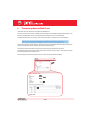
The PVI-AEC-EVO is a monitoring and checking system for photovoltaic systems made with Power-One Aurora
products.
The product allows to acquire parameters from the inverter and string-comb (in accordance with the design of the
central inverter monitoring system) through the RS485 line with the Power-One proprietary protocol.
The system is equipped with two equivalent RS485 ports and each of them allows a maximum of 62 string inverters
or 62 55kW conversion modules to be acquired.
The system is equipped with three analog inputs for the connection of sensors for the measurement of
environmental parameters:
The system also has six digital inputs for acquiring state signals (for example auxiliary contacts of power switches)
which are associated with state alarm conditions.
With respect to the user interface, the system is equipped with a 2x16 character display and four keys as well as an
integrated webserver with htm pages which are accessible through LAN connection.
The initial system configuration (check that the inverter parameters are acquired, analog inputs configuration, LAN
network parameters configuration) can be carried out completely through the display and keys; for displaying the
detailed parameters of the inverters and/or of the string-combs, as well as for the advanced configurations it is
necessary to access the pages of the integrated web server.
The PVI-AEC-EVO works together with a free web portal service: The system periodically transmits the data to the
portal management server and graphically shows the data on web pages which are accessible through an account
that can be requested from Power-One customer service.
The portal can also be used for sending alarm, report and FW update notification emails: The system FW can be
updated directly through the portal without the need for technical intervention on site.
The FW can also be updated locally without connecting to the portal.
2 - EN
EN - ENGLISH
Monitoring System
B.
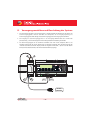
User interface and use of the display
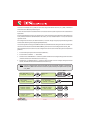
The system features a 2x16 character display,four buttons for navigating menus,and three LEDs to indicate device status.
Using the display and the buttons on the front panel it is possible to perform the initial configuration of the system (check
of parameter acquisition from inverter,analog input configuration,and configuration of LAN network parameters).
For displaying the detailed parameters of the inverters and/or of the string-combs, as well as for the advanced
configurations it is necessary to access the internal web server following the procedure described in paragraph H.
A list of functions accessible from the display is shown in the table in Appendix 3.
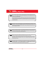
Power ON
Bus ON
Fault
Power supply available
Power supply not available
Power supply of the expansion BUS available Power supply of the expansion BUS not available
/
/
/
/
/
'Enter' button. Used to confirm an action,to access the main menu or the sub-menu corresponding to
the selected entry (indicated by the > symbol),or to go to the next digit to change.
'Down' button. Used to scroll down through the menu items, or to scroll the numerical scale in
descending order.
'Up' button. Used to scroll up through the menu items, or to scroll the numerical scale in ascending
order.
'Esc' button. Used to return to the previous menu or to return to the previous digit to change.
To perform the initial configuration it is necessary to access the various display menus as administrator.
Press the 'ENTER' key (
) and insert password
: To insert the password press the arrow keys (
) to
change the value and the 'ENTER' key to confirm the value. This password gives access to all the display setting submenus.
3 - EN
EN - ENGLISH
Monitoring System
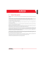
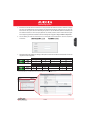
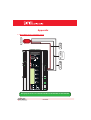
C.
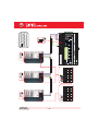
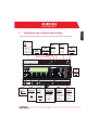
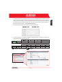
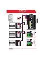
Pin-Out of System Connectors
The diagram below shows the pin-out of the connectors which allow the system connection.
J5
RELAY
1) RELAY 1
2) RELAY 1_RTN
3) RELAY 2
4) RELAY 2_RTN
5) RELAY 3
6) RELAY 3_RTN
J17
S2
J12
120Ω TERM.
RS485/1
GROUND
1
2
3
4
5
RS485/1
1) RTN
2) - T/R
3) +T/R
4) +5V
6
J15
RS485/2
1) RTN
2) - T/R
3) +T/R
4) +5V
4 3 2 1
S1
120Ω TERM.
RS485/2
4 3 2 1
J9
EXPANSION
BUS
1
J7
LAN
IEEE802.3u
2
J18
BATTERY IN
1) + Batt.
2) - Batt.
NOTE:
Only for dedicated
accessory
PVI-BATTERY-PACK
2
1
J8
Vin DC
1) + Vcc
2) - Vcc
INPUT DC:
24 V DC 0,3 A
NOTE:
Use the provided
power supply
1 2 3 4 5 6
J3
ANALOG INPUT
PT100/1000
1) PT_ALIM
2) PT_SENSE
3) PT_RTN
4) AIn_RTN
5) AIn 1
6) AIn 2
4 - EN
1 2 3 4 5 6
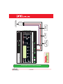
J20
1 2 3 4 5 6
DIGITAL I/O
1) RTN 1
2) RTN 1
3) DO_PWM 2
4) DO_PWM 1
5) DIn 1
6) DIn_RTN
J4
DIGITAL I/O
1) DIn 2
2) DIn 3
3) DIn 4
4) DIn_RTN
5) DIn 5
6) DIn 6
D.
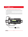
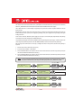
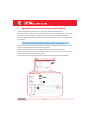
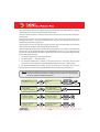
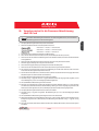
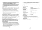
Power Supply Connections and System Start Up
1. Connect the power supply to the power supply network (110/230V 50/60Hz): the "Power" led on the power
supply will light up steadily.Check that the output voltage of the power supply is 24Vdc.Disconnect the power
supply from the power supply network.
2. Connect the output of the power supply to the power supply terminal block of the PVI-AEC-EVO respecting the
polarity and using the wiring provided.
3. Connect the power supply to the power supply network: After a first starting phase (lasting about 30 seconds)
during which the system is not able to receive any input from the user, the green "PowerOn" led will remain lit.
The message“PVI-AEC-EVO...." (in the first of the two lines) and date/time (in the second of the two lines) will
be displayed.
-
-
+
+
Output DC
24V 0.75A
STEP POWER
DC
OK
Input AC
100-240V
L(+)
L(+)
2
1
N(-)
N(-)
-Vcc
+Vcc
50-60 Hz
100-240 V~
5 - EN
EN - ENGLISH
Monitoring System
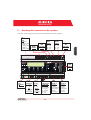
E.
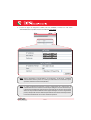
Date and time settings
1. Enter the main menu as administrator (See par.'B').
2. Access the menu 'SETTINGS' > 'DATALOGGER' and then select the 'SET DATE' sub-menu. This enables to set the
correct date in the system.
3. Return to the menu 'DATALOGGER' and then select the 'SET TIME' sub-menu. This enables to set the correct time
in the system.
SET PIN TO 0010
F.
PVI-AEC-EVO ......
12.00.00 01/01/11
ENTER
menu pin
0***
>settings
change password
ENTER
>set date
set time
ENTER
>set date
01/01/11
>set time
network
ENTER
>set time
12.00.00
>datalogger
io settings
NEXT
DIGIT
ENTER
CHANGE VALUE
NEXT
FIELD
ENTER
CHANGE VALUE
NEXT
FIELD
ENTER
CHANGE VALUE
ENTER
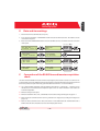
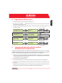
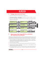
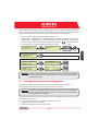
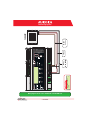
Connection of the RS485 line and inverter acquisition
check
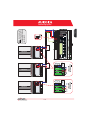
The connection of the RS485 line must be carried out respecting the pin-outs of the J15 and/or J17 connectors. It is
recommended to connect the RS485 line when all the equipment is switched off (both the monitoring system and
the inverters) and to start up the monitoring system first and then the inverters. It is recommended to:
l
Use a cable for RS485 applications with the following characteristics: 1 twisted pair + 1 conductor or two
twisted pairs, Screen and characteristic Impedance equal to 120Ω. For further information on the cable to be
used refer to Appendix 2.
l
Make sure the signals correspond.
l
Make sure that all three lines (+T/R,-T/R and RTN) are connected according to the diagrams on pages 8 - 9.
l
Make sure that the communication line screen is grounded in one single point (according to the diagrams on
pages 8 - 9).
l
Make sure that each element in the chain (each inverter or each 55kW module) has a RS485 address that is
different from the others.This address can be set via the display of the inverter.
6 - EN
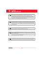
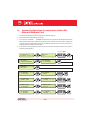
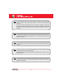
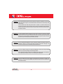
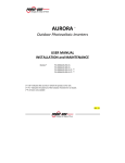
When connecting multiple units (string inverter or/and 55kW conversion modules) it is necessary
to wire the RS485 communication line according to the daisy-chain diagram (enter-exit).
The last inverter of the daisy-chain must be 'terminated' by activating the termination resistance of
the 120Ω communication line through switching the dip-switch located on the motherboard in the
string inverters,and inside each framework of the central inverters.
The maximum number of units (string inverters or/and 55kW conversion modules) that can be
connected to a RS485 port of the PVI-AEC-EVO is 62. In order to connect a number of units greater
than 62 it is necessary to use the second RS485/2 port respecting the same wiring diagram used for
the main RS485/1 port.
In case of mixed systems, the presence of both string inverters and central inverters on the same
RS485 line is permitted.To wire this line follow all the directions above.
All inverters (except for models PVI-5000/6000) have a clamp that allows giving continuity to the
cable screen of the RS485 line.
For single-phase inverters this clamp is indicated by the words LNK, for three-phase inverters it is
indicated by SCLD and for central inverters by X23.
For further details on the wiring of the RS485 line and/or the activation of the termination
resistances,refer to the user manual of string inverters and to the user manual of central inverters.
7 - EN
AURORA
8 - EN
+T/R
RTN
RS485
+T/R
-T/R
ON
OFF
120Ω
Term.
Resistor
ON
OFF
120Ω TERM.
RESISTOR ON
120Ω TERM.
RESISTOR
RTN
RTN +T/R -T/R
RS485
-T/R
AURORA
-T/R
+T/R
RTN
-T/R
ON
OFF
ON
OFF
120Ω
Term.
Resistor
120Ω TERM.
RESISTOR
RTN
120Ω TERM.
RESISTOR OFF
RTN +T/R -T/R
RS485
+T/R
RS485
+T/R
RS485
ON
OFF
120Ω
Term.
Resistor
4 3 2 1
120Ω TERM.
RESISTOR ON
4 3 2 1
RTN
+T/R
-T/R
Make sure that each
inverter in the chain has a
RS485 address that is
different from the others.
EN - ENGLISH
Monitoring System
RTN
-T/R
AURORA
9 - EN
A
A
X20 X21 X22 X23 X24 X25 X26 X27
D
D
X20 X21 X22 X23 X24 X25 X26 X27
X20 X21 X22 X23 X24 X25 X26 X27
RTN +T/R -T/R
A
RTN +T/R -T/R
D
A
120Ω TERM.
RESISTOR OFF
D
X20 X21 X22 X23 X24 X25 X26 X27
120Ω TERM.
RESISTOR ON
A
D
X20 X21 X22 X23 X24 X25 X26 X27
120Ω TERM.
RESISTOR OFF
4 3 2 1
120Ω TERM.
RESISTOR ON
4 3 2 1
RTN
+T/R
-T/R
Make sure that each
55 kW module in the chain
has a RS485 address that is
different from the others.
EN - ENGLISH
Monitoring System
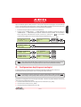
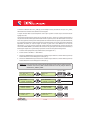
After carrying out these checks, start up first the monitoring system and then the inverters. The system automatically
carries out a scan of the RS485 bus and automatically detects the available inverters.The presence of the inverters can be
checked directly from the display.
1. Enter the main menu as administrator (See par.'B').
2. Access the 'CURRENTVALUES' > 'ENERGY INVERTERS' menu (to display the string inverters) and/or 'CURRENTVALUES'
> 'ENERGY RACK' (to display the 55kW conversion modules). The number of inverters detected during the scan will
be displayed; the list of the monitored inverters identified by the Serial Number (S/N) can be displayed by scrolling
using the arrow keys (
).
SET PIN TO 0010
PVI-AEC-EVO ......
12.00.00 01/01/11
ENTER
>CURRENT VALUE
SETTINGS
ENTER
>ENERGY INVERTERS
ENERGY RACK
ENTER
>ENERGY RACK
ENERGY PLANT
ENTER
menu pin
0***
CHANGE VALUE
30 INVERTERS
>INVERTER SN 123456
RACK
>RACK
N. 1
SN 123456
NEXT
DIGIT
ENTER
CHANGE
INVERTER
CHANGE
RACK
The time necessary for the PVI-AEC-EVO to scan and acquire the inverters depends on the number of
inverterspresentonthesameline(sometimesseveralminutes).
G.
Configuration of the Analog Inputs
The connection of the analogue sensors must be carried out respecting the pin-outs of the J3 connector.
The system has two 0-10Vdc inputs and a PT100/1000 input.
To each analogue input (both 0-10Vdc and PT100/1000 types) it is possible to connect only one analog
sensor. Itisthereforenotpossibletoconnectmultiplesensorsonthesameanaloginput.
With respect to the connection of the PT100/1000 sensors,the system is able to carry out the sensor reading through the
connection of three-wires:
l A sensor power supply line which is also used as a sense line (PT_ALIM);
l A (return) reading line (PT_SENSE);
l A power supply closing line (PT_RTN).
10 - EN
The measurement is carried out between the PT_ALIM (which as mentioned earlier also carries out the sense function)
and the PT_SENSE therefore the element to be measured must be wired between these two signals.
The PT100/PT1000 sensor is automatically recognised by the system and is therefore acquired without the need for
further settings.
Regarding the connection of the sensors with output range 0...10Vdc,these must be powered and the power supply can
be taken directly from the system power supply; the grounding of the power supply and the grounding of the signal
reading is the same.
For the sensor connection, beside the power supply, it is necessary to connect the signal proportionally to the quantity
measured at one of the two analog inputs available (Aln1/Aln2).
The grounding of the signal to be measured (if different from the grounding of the power supply – within the Power-One
sensor range only in the wind speed sensor PVI-AEC-WIND-COMPACT) must be connected to the Aln_RTN clamp.
After carrying out the connections it is necessary to configure the sensor in the system so that the correct quantity is
acquired:
1. Enter the main menu as administrator (See par.'B').
2. Access the menu 'SETTINGS' > 'IO SETTINGS'.
3. Select the ANALOG INPUT1 item and then select the sensor model connected to the AIn1 input of the system (the
selected model will be identified with an asterisk (*) ).
4. Select the ANALOG INPUT2 item and then select the sensor model connected to the AIn2 input of the system (the
selected model will be identified with an asterisk (*) ).
In case of connecting PT100/1000 sensors with only two terminals,connect a terminal to the PT_SENSE
clampandaterminaltothePT_RTNclamp,thenmakeajumperbetweenPT_ALIMandPT_SENSE.
SET PIN TO 0010
PVI-AEC-EVO ......
12.00.00 01/01/11
ENTER
menu pin
0***
>settings
change password
ENTER
>io settings
UPGRADE FIRMWARE
>ANALOG INPUT1
ANALOG INPUT2
ENTER
>ANALOG INPUT1
T1000-INTEGR
*
>ANALOG INPUT2
PULSE IN1
ENTER
>ANALOG INPUT2
RAD-13TC
*
11 - EN
CHANGE VALUE
NEXT
DIGIT
ENTER
CHANGE
SENSORS
ENTER
CHANGE
SENSORS
ENTER
ENTER
EN - ENGLISH
Monitoring System
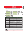
To read the measurements of the sensors and to check their accuracy follow the instructions below:
1. Enter the main menu as administrator (See par.'B').
2. Access the menu 'CURRENT VALUES' > 'ANALOG VALUE'. The quantity value will be displayed for each of the
analog inputs.
SET PIN TO 0010
PVI-AEC-EVO ......
12.00.00 01/01/11
ENTER
menu pin
0***
>CURRENT VALUE
SETTINGS
ENTER
>ANALOG VALUE
DIGITAL VALUE
>T1000-INTEGR
20.0 DEGC
MODEL
CHANGE VALUE
NEXT
DIGIT
ENTER
ENTER
AN1
CHANGE
INPUT
TYPE
DISPLAY IDENTIFICATION CODE
2
PVI-AEC-IRR
Radiation Sensor (W/m --> V)
IRR
PVI-AEC-IRR-T
Radiation Sensor with integrated cell
Temperature Sensor (W/m2 / °C --> V)
IRR-T_Irr / IRR-T_Temp
PVI-AEC-RAD-13TC
Radiation Sensor (W/m --> V)
RAD-13TC
PVI-AEC-RAD-13TC-T
Radiation Sensor with integrated cell
2
Temperature Sensor (W/m / °C --> V)
RAD-13-TC-T_Irr /
RAD-13-TC-T_Temp
PVI-AEC-CONV-T100
PT100 Sensor connected to PT100/0...10Vdc
Converter (°C --> V)
T100-ADH-CONV /
T100-BOX-CONV
PVI-AEC-T1000-INTEGR
Ambient Temperature Sensor connected
to PT100/0...10Vdc Converter (°C --> V)
T1000-INTEGR
PVI-AEC-T100-ADH
Adhesive module temperature sensor
(back cell) PT100
T100-ADH
PVI-AEC-T100-BOX
Ambient Temperature Sensor PT100
T100-BOX
PVI-AEC-T1000-BOX
Ambient Temperature Sensor PT1000
T1000-BOX
PVI-AEC-WIND-COMPACT
Wind Speed Sensor (m/s --> V)
WIND-COMPACT
PVI-AEC-WIND-DIR
Wind Direction Sensor (° --> V)
WIND-DIR
2
For the connection of sensors mentioned above refer to diagrams in Appendix 1.
12- EN
H.
System Configuration for connection to the LAN
Network (Ethernet Port)
1. Power on the system and wait for the start up phase to complete (ref.par.D).
2. Enter the main menu as administrator (See par.'B').
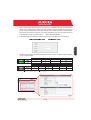
3. Access the menu “SETTINGS” > “NETWORK”. The parameters for connection to the LAN network (IP address,
Subnet mask, Gateway) may be modified using the items of the "Network" menu.This allows to configure the
system for connection to the network (by means of an Ethernet patch cable) and/or for direct connection to a
PC/laptop (by means of an Ethernet cross cable).
4. At the end of the setting operations, return to the main screen, then switch off and switch on the system to
make the settings take effect.
SET PIN TO 0010
PVI-AEC-EVO ......
12.00.00 01/01/11
ENTER
menu pin
0***
>settings
change password
ENTER
>datalogger
io settings
>NETWORK
SET DATA
ENTER
>IP method
ip setting
ENTER
>IP method
manual
>IP SETTING
SUBNET MASK
ENTER
>IP SETTING
10.200. 4. 51
>SUBNET MASK
ip gateway
ENTER
>subnet mask
255.255. 0.
0
>IP gateway
ip method
ENTER
>IP gateway
10.200. 1.
1
13 - EN
CHANGE VALUE
NEXT
DIGIT
ENTER
ENTER
CHANGE
METHOD
ENTER
CHANGE VALUE
NEXT
DIGIT
ENTER
CHANGE VALUE
NEXT
DIGIT
ENTER
CHANGE VALUE
NEXT
DIGIT
ENTER
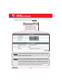
5. When starting up again the system the webserver pages will be accessible through Ethernet connection (direct
connection with a PC/Laptop or through a LAN network) using the IP address set. To access the system
webserver pages, after having connected the system to a LAN network (Ethernet patch cable) or directly to a
PC/Laptop (Ethernet cross cable), open an internet browser (e.g.. Internet Explorer) and type into the address
bar the following address:
http://<system IP address>
6. To access the webserver pages it is necessary to insert a username and a password:
7. Access the configuration page (CONFIG) of the system (PLANT) and insert the installation GPS coordinates
according to one of the following formats:
*
14- EN
EN - ENGLISH
Monitoring System
8. Access the configuration page (CONFIG) of the network (NETWORK) and check that in section 'DATA TRANSFER',
under item 'IP Address Portal' there is the IP address 151.22.100.44 .
If the setting 'IP Portal Address' does not correspond to 151.22.100.44, change it by entering the
above-mentioned address and press 'Confirm' to activate it. After this operation, reset the system
(ON-OFF).
To make the system fully functioning it is essential that the same system is constantly connected
to the internet so that it is able to communicate with the Power-One server. This is essential to
graphically shows the data on web pages as well as for sending alarm and/or report messages.It is
essential that the LAN network in which the PVI-AEC-EVO is wired is such that it allows the
connection to the IP address 151.22.100.44 to be reached through port 80,so that the PVI-AEC-EVO
is able to communicate with the portal management server.
15 - EN
I.
Request Form for a New System on Web Portal
(for the display of the contact)
(to access the portal)
(to access the portal – at least 8 characters)
(to send alarm and/or report messages according
to the customized configuration set by the user)
(Indicated on the label of the PVI-AEC-EVO)
(for the creation of the system linked to the
PVI-AEC-EVO(s))
(requested for setting the GPS coordinates –
enter also the latitude and longitude of the
system, if available)
l
l
l
l
l
l
Theformmustbesent ONLYAFTER establishingtheconnectiontotheInternetofthePVI-AEC-EVO.
If you would like to request the activation of a portal linked to a number of data loggers installed in
varioussystems,youarerequestedtofillinaformforeachsystem.
Thenewaccountthatwillbecreatedshallhaveadministratorprivilegesonthesystemassociatedwithit.
With the administrator account you can modify the portal settings and create further accounts with
usercredentials.
Withtheuseraccountyoucanonlydisplaythesystemdata.
Toaccesstheportalyouneedtoconnecttothewebsite:
http://151.22.100.44/aurora
andtousethecredentialsindicatedinthetableabove.
16- EN
EN - ENGLISH
Monitoring System
L.
Firmware update via Web Portal
The firmware of the PVI-AEC-EVO can be updated via the Web Portal.
Each time a new firmware version is available, a warning will appear on the Web Portal pages indicating that a new
firmware is available.Moreover,users associated with the system will receive an e-mail notification.
To upgrade the firmware it is necessary to click on the link in the alert or on the link in the e-mail notification.
This will open a page where authorization is requested in order to proceed with the firmware update,and where the
location of memory (FAT) where to install the new firmware will be requested.
The maximum number of firmware versions that the memory can keep is 4 (FAT0,FAT1,FAT2,FAT3).
It is advisable to install the new version of the firmware into an empty memory location, or in the memory location
containing the oldest version of the firmware.
After selecting the desired memory location,click on 'Confirm' to proceed with the installation.
17 - EN
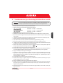
M. Firmware updating procedure via SD Card
The firmware update via SD card should be carried out only if it is not possible to update the firmware
viatheWebPortal.
1. Access the display by entering the user password 0000.
2. Check and note the current firmware versions installed:
Information > Product > Firmware AVR
Information > Product > Firmware Display
Information > Product > Firmware IO
3. Turn off the PVI-AEC-EVO and wait at least one minute.
4. Disconnect all available connections from the PVI-AEC-EVO (RS458 line(s),LAN connection,sensors).
5. Remove the SD Card from the slot on the PVI-AEC-EVO front panel by pressing the SD Card gently.
6. Insert the SD Card into the SD Card reader or into to the SD Card reader slot of the PC.
7. Delete the folders upgrade,web,lang and config from the SD Card.
8. Copy the new folders upgrade,web,lang and config into the root of the SD Card.
9. Remove the SD Card from the SD Card reader or from the SD Card reader slot.
10. Insert the SD Card into the slot on the PVI-AEC-EVO front panel by pressing the SD Card gently to lock it into place.
11. Turn on the PVI-AEC-EVO and wait about one minute.(N.B.: Power failure during update may cause serious damage
to the device).
12. Access the display by entering the administrator password 0010.
13. Access the menu Settings > Upgrade Firmware > Upgrade AVR. If the procedure was carried out correctly,the
system will to confirm the command by displaying the message“Are you sure?”.
14. Press ENTER to update the firmware.
15. Wait until the update (during the update the message “Waiting for Load” is displayed) and the reboot are
completed (during reboot the message “Waiting for Reboot”is displayed).The reboot is completed when date and
time are displayed.
16. Access the display by entering the administrator password 0010.
17. Access the menu Settings > Upgrade Config. The system will ask to confirm the command by displaying the
message“Are you sure?”.
18. Press ENTER to update the PVI-AEC-EVO configuration.
19. During the update the message “Waiting for Load” will be displayed. Wait until the configuration update is
completed. At the end of the update the menu Settings > Upgrade Config will be displayed.
20. Switch off the system,restore all connections (RS485 line(s),LAN connection,sensors),then switch on the system.
18- EN
EN - ENGLISH
Monitoring System
INDICE
A.
B.
C.
D.
E.
F.
G.
H.
I.
L.
M.
1 - IT
A.
Descrizione del Prodotto
Il PVI-AEC-EVO è un sistema di monitoraggio e controllo degli impianti fotovoltaici realizzati con prodotti PowerOne Aurora.
Il prodotto consente l'acquisizione dei parametri da inverter e stringcomb (secondo l'architettura di monitoraggio
degli inverter centralizzati) attraverso linea RS485 con protocollo proprietario Power-One.
Il sistema dispone di due porte RS485 (equivalenti tra loro) che permettono l'acquisizione, ciascuna, di 62 inverter
di stringa o di 62 moduli di conversione da 55kW.
Il sistema dispone di tre ingressi analogici per il collegamento di sensori per la misura dei parametri ambientali:
Power-One offre,a catalogo,una gamma completa di sensori di irraggiamento,temperatura e velocità del vento.
Il sistema mette a disposizione anche sei ingressi digitali per l'acquisizione di segnali di stato (ad esempio contatti
ausiliari di interruttori di potenza) a cui sono associate condizioni di allarme di stato.
Relativamente all'interfaccia utente,il sistema dispone di un display 2x16 caratteri e quattro pulsanti oltre che di un
webserver integrato di pagine htm accessibile attraverso connessione LAN.
La configurazione iniziale del sistema (verifica dell'acquisizione dei parametri da inverter, configurazione degli
ingressi analogici, configurazione dei parametri di rete LAN) può essere eseguita interamente attraverso il display
ed i pulsanti; per la visualizzazione dei parametri di dettaglio degli inverter e/o delle stringcomb nonchè per le
configurazioni avanzate è necessario accedere alle pagine di webserver integrato.
Il PVI-AEC-EVO lavora in abbinamento ad un servizio di portale web: il sistema periodicamente trasmette i dati al
server di gestione del portale che presenta i dati in forma grafica su pagine web accessibili tramite account da
richiedere al customer service di Power-One.
Il portale è anche funzionale all'invio delle mail di allarme, di resoconto e di notifica di presenza di aggiornamenti
FW: l'aggiornamento del FW del sistema può essere effettuato direttamente da portale senza necessità
dell'intervento tecnico in loco.
Il FW può anche essere aggiornato localmente ovvero in assenza di connessione al portale.
2 - IT
IT - ITALIANO
Monitoring System
B.
Interfaccia Utente ed utilizzo del display
Il sistema dispone di un display 2x16 caratteri, quattro pulsanti per la navigazione nei menù, e tre LED che indicano
lo stato del dispositivo.
Attraverso l’uso del display e dei pulsanti posti sul pannello frontale è possibile effettuare la configurazione iniziale
del sistema (verifica dell'acquisizione dei parametri da inverter, configurazione degli ingressi analogici,
configurazione dei parametri di rete LAN).
Per la visualizzazione dei parametri di dettaglio degli inverter e/o delle stringcomb nonchè per le configurazioni
avanzate è necessario accedere al webserver interno seguendo la procedura descritta nel paragrafo H.
Una lista delle funzioni accessibili da display è mostrata nella tabella presente in Appendice 3.
Power ON
Bus ON
Fault
Alimentazione presente
Alimentazione assente
Alimentazione del BUS di espansione Alimentazione assente del BUS di espansione
/
/
/
/
/
Pulsante “Enter”. Viene utilizzato per confermare un’ azione, per accedere al menù principale o al
sottomenù corrispondente alla voce selezionata (indicata dal simbolo >), o per passare alla cifra
successiva da modificare.
Pulsante “Down”. Viene utilizzato per scorrere le voci dei menù verso il basso, oppure per scorrere la
scala numerica in ordine decrescente.
Pulsante “Up”. Viene utilizzato per scorrere le voci dei menù verso l’alto, oppure per scorrere la scala
numerica in ordine crescente.
Pulsante“Esc”. Viene utilizzato per tornare al menù precedente o per tornare alla cifra precedente da
modificare.
Per poter effettuare le configurazioni iniziali, è necessario accedere come amministratore ai vari menù del display.
Premere il tasto“ENTER”(
) ed inserire la password
: per inserire la password premere i tasti freccia (
)
per modificare il valore ed il tasto“ENTER”per confermare il valore. Attraverso questa password è possibile accedere a
tutti i sottomenu di impostazione del display.
3 - IT
Monitoring System
Piedinatura dei connettori del sistema
IT - ITALIANO
C.
Lo schema di seguito riporta la piedinatura dei connettori che permettono la connessione del sistema.
J5
RELAY
1) RELAY 1
2) RELAY 1_RTN
3) RELAY 2
4) RELAY 2_RTN
5) RELAY 3
6) RELAY 3_RTN
J17
S2
J12
120Ω TERM.
RS485/1
GROUND
1
2
3
4
5
RS485/1
1) RTN
2) - T/R
3) +T/R
4) +5V
6
J15
RS485/2
1) RTN
2) - T/R
3) +T/R
4) +5V
4 3 2 1
S1
120Ω TERM.
RS485/2
4 3 2 1
J9
EXPANSION
BUS
1
J7
LAN
IEEE802.3u
2
J18
BATTERY IN
1) + Batt.
2) - Batt.
NOTE:
Only for dedicated
accessory
PVI-BATTERY-PACK
2
1
J8
Vin DC
1) + Vcc
2) - Vcc
INPUT DC:
24 V DC 0,3 A
NOTE:
Use the provided
power supply
1 2 3 4 5 6
J3
ANALOG INPUT
PT100/1000
1) PT_ALIM
2) PT_SENSE
3) PT_RTN
4) AIn_RTN
5) AIn 1
6) AIn 2
4 - IT
1 2 3 4 5 6
J20
1 2 3 4 5 6
DIGITAL I/O
1) RTN 1
2) RTN 1
3) DO_PWM 2
4) DO_PWM 1
5) DIn 1
6) DIn_RTN
J4
DIGITAL I/O
1) DIn 2
2) DIn 3
3) DIn 4
4) DIn_RTN
5) DIn 5
6) DIn 6
D.
Collegamenti di alimentazione del sistema
1. Collegare l'alimentatore alla rete di alimentazione (110/230V 50/60Hz):il led“Power”dell'alimentatore si accenderà
stabilmente. Verificare che la tensione di uscita dell'alimentatore sia 24Vdc. Scollegare l'alimentatore dalla rete di
alimentazione.
2. Collegare l'uscita dell'alimentatore alla morsettiera di alimentazione del PVI-AEC-EVO (rispettando la polarità)
utilizzando il cablaggio fornito a corredo.
3. Collegare l'alimentatore alla rete di alimentazione: dopo una prima fase di avvio (della durata di circa 30
secondi), durante la quale il sistema non è in grado di ricevere input da parte dell'utente, il led verde “Power ON”
rimarrà stabilmente acceso.A display sarà visibile la scritta“PVI-AEC-EVO....”(nella prima delle due righe) e data/ora
(nella seconda delle due righe).
-
-
+
+
Output DC
24V 0.75A
STEP POWER
DC
OK
Input AC
100-240V
L(+)
L(+)
2
1
N(-)
N(-)
-Vcc
+Vcc
50-60 Hz
100-240 V~
5 - IT
Monitoring System
Impostazione di data ed ora
1. Accedere al menù principale come amministratore (Rif.Par.“B”).
2. Accedere al menu “SETTINGS” > “DATALOGGER” quindi selezionare il sottomenù “SET DATE”. Sarà possibile
impostare la data corretta nel sistema.
3. Ritornare al menù “DATALOGGER” , quindi selezionare il sottomenù “SET TIME”. Sarà possibile impostare l'ora
corretta nel sistema.
SET PIN TO 0010
F.
PVI-AEC-EVO ......
12.00.00 01/01/11
ENTER
menu pin
0***
>settings
change password
ENTER
>set date
set time
ENTER
>set date
01/01/11
>set time
network
ENTER
>set time
12.00.00
>datalogger
io settings
NEXT
DIGIT
ENTER
CHANGE VALUE
NEXT
FIELD
ENTER
CHANGE VALUE
NEXT
FIELD
ENTER
CHANGE VALUE
ENTER
Collegamenti della linea RS485 e verifica
dell’acquisizione degli inverter
Il collegamento della linea RS485 deve essere eseguito rispettando la piedinatura dei connettori J15 e/o J17. Si consiglia
di collegare la linea RS485 quando tutte le apparecchiature sono spente (sia il sistema di monitoraggio sia gli inverter) e di
mettere in servizio prima il sistema di monitoraggio e successivamente gli inverter. Si raccomanda di:
l
Utilizzare un cavo per applicazioni RS485 avente le seguenti caratteristiche:1 coppia twistata + 1 conduttore oppure
due coppie twistate, Schermo ed Impedenza caratteristica pari a 120Ω. Per maggiori informazioni in merito ad il
cavo da utilizzare fare riferimento all’Appendice 2.
l
Accertarsi della corrispondenza dei segnali.
l
Accertarsi che tutte le tre linee (+T/R,-T/R e RTN) siano collegate in accordo agli schemi presenti nelle pagine 8 - 9.
l
Accertarsi che lo schermo della linea di comunicazione sia riferito a terra in un solo punto (in accordo agli schemi nelle
pagine 8 - 9).
l
Accertarsi che ogni elemento della catena (ovvero ogni inverter oppure ogni modulo da 55kW) abbia un indirizzo
RS485 differente rispetto agli altri. Tale indirizzo è impostabile attraverso il display dell’inverter.
6 - IT
IT - ITALIANO
E.
In caso di collegamento di più unità (inverter di stringa o/e moduli di conversione da 55kW) è
necessario cablare la linea di comunicazione RS485 in accordo allo schema daisy-chain
(entra-esci).
L’ultimo inverter della catena daisy-chain deve essere “terminato” attivando la resistenza di
terminazione della linea di comunicazione da 120Ω, attraverso la commutazione del dip-switch
posto sulla scheda madre negli inverter di stringa, ed all’interno di ogni framework negli inverter
centralizzati.
Il numero massimo di unità (inverter di stringa o/e moduli di conversione da 55kW) collegabili ad
una porta RS485 del PVI-AEC-EVO è 62; per collegare un numero maggiore di 62 unità è necessario
utilizzare la seconda porta RS485/2 rispettando lo stesso schema di collegamento utilizzato per la
porta RS485/1 principale.
Nel caso di impianti misti, la compresenza di inverter di stringa e di inverter centralizzati sulla
stessa linea RS485 è permessa. Per cablare tale linea è necessario rispettare tutte le indicazioni
precedenti.
In tutti gli inverter (ad eccezione dei modelli PVI-5000/6000) è presente un morsetto chepermettedi
darecontinuitàalloschermodelcavodellalineaRS485.
Negli inverter monofase tale morsetto è indicato con la dicitura LNK,nei trifase è indicato con SCLD,nei
centralizzaticonX23.
Per ulteriori dettagli in merito alla cablatura della linea RS485 e/o all’attivazione delle resistenze
di terminazione, fare riferimento al manuale utente degli inverter di stringa e al manuale utente
degli inverter centralizzati.
7 - IT
AURORA
8 - IT
+T/R
RTN
RS485
+T/R
-T/R
ON
OFF
120Ω
Term.
Resistor
ON
OFF
120Ω TERM.
RESISTOR ON
120Ω TERM.
RESISTOR
RTN
RTN +T/R -T/R
RS485
-T/R
AURORA
-T/R
+T/R
RTN
-T/R
ON
OFF
ON
OFF
120Ω
Term.
Resistor
120Ω TERM.
RESISTOR
RTN
120Ω TERM.
RESISTOR OFF
RTN +T/R -T/R
RS485
+T/R
RS485
+T/R
RS485
ON
OFF
120Ω
Term.
Resistor
4 3 2 1
RTN
+T/R
-T/R
IT - ITALIANO
4 3 2 1
120Ω TERM.
RESISTOR ON
Accertarsi che ogni
inverter della catena abbia
un indirizzo RS485 differente
rispetto agli altri.
Monitoring System
RTN
-T/R
AURORA
9 - IT
A
A
X20 X21 X22 X23 X24 X25 X26 X27
D
D
X20 X21 X22 X23 X24 X25 X26 X27
X20 X21 X22 X23 X24 X25 X26 X27
RTN +T/R -T/R
A
RTN +T/R -T/R
D
A
120Ω TERM.
RESISTOR OFF
D
X20 X21 X22 X23 X24 X25 X26 X27
120Ω TERM.
RESISTOR ON
A
D
X20 X21 X22 X23 X24 X25 X26 X27
120Ω TERM.
RESISTOR OFF
4 3 2 1
120Ω TERM.
RESISTOR ON
4 3 2 1
RTN
+T/R
-T/R
Accertarsi che ogni
modulo da 55 kW della
catena abbia un indirizzo
RS485 differente rispetto agli
altri.
Dopo aver effettuato queste verifiche, mettere in servizio prima il sistema di monitoraggio e successivamente gli
inverter. Il sistema effettua automaticamente la scansione del bus RS485 e quindi rileva in automatico gli inverter
presenti. Per verificare la presenza degli inverter,si può agire direttamente da display.
1. Accedere al menù principale come amministratore (Rif.Par.“B”).
2. Accedere al menu “CURRENT VALUES” > “ENERGY INVERTERS” (per visualizzare gli inverter di stringa) e/o
“CURRENT VALUES” > “ENERGY RACK” (per visualizzare i moduli di conversione da 55kW). Verrà visualizzato il
numero degli inverter individuati nella scansione; scorrendo con i tasti freccia (
) sarà possibile
visualizzare la lista degli inverter monitorati identificati dal Serial Number (S/N).
SET PIN TO 0010
PVI-AEC-EVO ......
12.00.00 01/01/11
ENTER
>CURRENT VALUE
SETTINGS
ENTER
>ENERGY INVERTERS
ENERGY RACK
ENTER
>ENERGY RACK
ENERGY PLANT
ENTER
menu pin
0***
CHANGE VALUE
30 INVERTERS
>INVERTER SN 123456
RACK
>RACK
NEXT
DIGIT
ENTER
CHANGE
INVERTER
N. 1
SN 123456
CHANGE
RACK
Il tempo impiegato dal PVI-AEC-EVO per effettuare la scansione ed acquisire gli inverter può variare
dipendentemente dal numero degli inverter presenti sulla stessa linea (talvolta alcuni minuti).
G.
Configurazione degli ingressi analogici
Il collegamento dei sensori analogici deve essere effettuato rispettando la piedinatura del connettore J3.
Il sistema dispone di due ingressi di tipo 0-10 Vdc, ed un ingresso di tipo PT100/1000.
Per ogni ingresso analogico (sia del tipo 0-10 Vdc che PT100/1000) è possibile connettere un solo
sensore analogico. Non è quindi possibile connettere più sensori sullo stesso ingresso analogico.
Relativamente al collegamento di sensori del tipo PT100/1000, il sistema è in grado di effettuare la lettura dei
sensori attraverso il collegamento di tre fili:
l Una linea di alimentazione del sensore che funge anche come linea di Sense (PT_ALIM);
l Una linea di (ritorno della) lettura (PT_SENSE)
l Una linea di richiusura dell'alimentazione (PT_RTN).
10 - IT
IT - ITALIANO
Monitoring System
La misura viene effettuata tra PT_ALIM (che come detto svolge anche funzione di Sense) e PT_SENSE; l'elemento di
misura deve essere cablato tra questi due segnali.
Il sensore PT100/PT1000 viene automaticamente riconoscuito dal sistema e quindi acquisito senza necessità di ulteriori
impostazioni.
In merito al collegamento dei sensori con range di uscita 0...10Vdc,questi devono essere alimentati e l'alimentazione può
essere prelevata direttamente dall'alimentazione del sistema; la massa dell'alimentazione e la massa di lettura dei
segnali è a comune.
Per il collegamento del sensore, oltre all'alimentazione, è necessario collegare il segnale proporzionale alla grandezza
misurata ad uno dei due ingressi analogici disponibili (AIn1/AIn2).
La massa del segnale di misura (qualora differente dalla massa dell'alimentazione (nella gamma dei sensori Power-One
solo nel sensore di velocità vento PVI-AEC-WIND-COMPACT)) deve essere deve essere collegata al morsetto AIn_RTN.
Dopo aver effettuato le connessioni è necessario configurare il sensore nel sistema in modo da acquisire correttamente la
grandezza:
1. Accedere al menù principale come amministratore (Rif.Par.“B”).
2. Accedere al menù “SETTINGS” > “IO SETTINGS”.
3. Selezionare la voce ANALOG INPUT1 e selezionare quindi il modello di sensore collegato all'ingresso AIn1 del sistema
(il modello selezionato verrà identificato con un asterisco (*) ).
4. Selezionare la voce ANALOG INPUT2 e selezionare quindi il modello di sensore collegato all'ingresso AIn2 del
sistema (il modello selezionato verrà identificato con un asterisco (*) ).
In caso di collegamento di sensori PT100/1000 con due soli terminali, collegare un terminale al
morsetto PT_SENSE ed un terminale al morsetto PT_RTN; realizzare poi un ponticello tra PT_ALIM
e PT_SENSE.
SET PIN TO 0010
PVI-AEC-EVO ......
12.00.00 01/01/11
ENTER
menu pin
0***
>settings
change password
ENTER
>io settings
UPGRADE FIRMWARE
>ANALOG INPUT1
ANALOG INPUT2
ENTER
>ANALOG INPUT1
T1000-INTEGR
*
>ANALOG INPUT2
PULSE IN1
ENTER
>ANALOG INPUT2
RAD-13TC
*
11 - IT
CHANGE VALUE
NEXT
DIGIT
ENTER
CHANGE
SENSORS
ENTER
CHANGE
SENSORS
ENTER
ENTER
Monitoring System
1. Accedere al menù principale come amministratore (Rif.Par.“B”).
2. Accedere al menu “CURRENT VALUES” > “ANALOG VALUE”. Verrà visualizzato il valore della grandezza per
ciascuno degli ingressi analogici.
SET PIN TO 0010
PVI-AEC-EVO ......
12.00.00 01/01/11
ENTER
menu pin
0***
>CURRENT VALUE
SETTINGS
ENTER
>ANALOG VALUE
DIGITAL VALUE
>T1000-INTEGR
20.0 DEGC
MODELLO
CHANGE VALUE
NEXT
DIGIT
ENTER
ENTER
AN1
CHANGE
INPUT
TIPOLOGIA
IDENTIFICATIVO DISPLAY
2
PVI-AEC-IRR
Sensore Irraggiamento (W/m --> V)
IRR
PVI-AEC-IRR-T
Sensore Irraggiamento con sensore Temperatura
cella integrato (W/m2 / °C --> V)
IRR-T_Irr / IRR-T_Temp
PVI-AEC-RAD-13TC
Sensore Irraggiamento (W/m --> V)
RAD-13TC
PVI-AEC-RAD-13TC-T
Sensore Irraggiamento con sensore Temperatura
2
cella integrato (W/m / °C --> V)
RAD-13-TC-T_Irr /
RAD-13-TC-T_Temp
PVI-AEC-CONV-T100
Sensore PT100 collegato a convertitore
PT100/0...10Vdc (°C --> V)
T100-ADH-CONV /
T100-BOX-CONV
PVI-AEC-T1000-INTEGR
Sensore di temperatura ambiente con
convertitore 0...10Vdc integrato (°C --> V)
T1000-INTEGR
PVI-AEC-T100-ADH
Sensore di temperatura modulo (back cell)
PT100 adesivo
T100-ADH
PVI-AEC-T100-BOX
Sensore di temperatura ambiente PT100
T100-BOX
PVI-AEC-T1000-BOX
Sensore di temperatura ambiente PT1000
T1000-BOX
PVI-AEC-WIND-COMPACT
Sensore velocità vento (m/s --> V)
WIND-COMPACT
PVI-AEC-WIND-DIR
Sensore direzione vento (° --> V)
WIND-DIR
2
Per la connessione dei sensori sopra indicati fare riferimento agli schemi presenti in Appendice 1.
12 - IT
IT - ITALIANO
Per leggere le misure dei sensori e verificare la loro correttezza:
H.
Configurazione del sistema per la connessione
in rete LAN (porta Ethernet)
1. Alimentare il sistema ed attendere il completamento della fase di avvio (Rif.Par.”D”).
2. Accedere al menù principale come amministratore (Rif.Par.“B”).
3. Accedere al menù “SETTINGS” > “NETWORK”. Attraverso le voci del menu “NETWORK” sarà possibile
modificare i parametri di connessione alla rete LAN (Indirizzo IP, Subnet Mask, Gateway) in modo da
configurare il sistema per la connessione in rete e/o per la connessione diretta ad un PC/Laptop.
4. Al termine delle operazioni di impostazione,ritornare alla schermata principale,quindi spegnere e riaccendere
il sistema per rendere effettive le impostazioni.
SET PIN TO 0010
PVI-AEC-EVO ......
12.00.00 01/01/11
ENTER
menu pin
0***
>settings
change password
ENTER
>datalogger
io settings
>NETWORK
SET DATA
ENTER
>IP method
ip setting
ENTER
>IP method
manual
>IP SETTING
SUBNET MASK
ENTER
>IP SETTING
10.200. 4. 51
>SUBNET MASK
ip gateway
ENTER
>subnet mask
255.255. 0.
0
>IP gateway
ip method
ENTER
>IP gateway
10.200. 1.
1
13 - IT
CHANGE VALUE
NEXT
DIGIT
ENTER
ENTER
CHANGE
METHOD
ENTER
CHANGE VALUE
NEXT
DIGIT
ENTER
CHANGE VALUE
NEXT
DIGIT
ENTER
CHANGE VALUE
NEXT
DIGIT
ENTER
5. Al nuovo riavvio le pagine di webserver del sistema saranno accessibili attraverso connessione Ethernet
(diretta con PC/Laptop oppure attraverso rete LAN) utilizzando l'indirizzo IP impostato. Per accedere alle
pagine di webserver del sistema, dopo aver effettuato la connessione del sistema in rete LAN (cavo Ethernet
patch) oppure diretta a PC/Laptop (cavo Ethernet cross), aprire un browser internet (es. Internet Explorer) e
digitare nella barra degli indirizzi: http://<indirizzo IP del sistema>
6. Per accedere alle pagine di webserver è necessario inserire username e password:
7. Accedere alla pagina di configurazione (CONFIG) dell'impianto (PLANT) ed inserire le coordinate GPS
dell'installazione secondo uno dei seguenti formati:
*
14 - IT
IT - ITALIANO
Monitoring System
8. Accedere alla pagina di configurazione (CONFIG) della rete (NETWORK) e verificare che nella sezione
“DATATRANSFER”alla voce“Ip Address Portal”si trovi l’indirizzo IP 151.22.100.44 .
Qualora l’impostazione “Ip Portal Address” non corrisponda a 151.22.100.44 , modificarla
immettendo tale indirizzo e premere su “Confirm” per renderla attiva. Successivamente a questa
operazione,effettuare il reset del sistema (ON-OFF).
Per rendere completamente funzionante il sistema è indispensabile che il sistema stesso sia
continuativamente connesso ad internet in modo da poter dialogare con il server di Power-One per
le operazioni di visualizzazione grafica dei dati su pagine web oltre che per l'invio di messaggi di
allarme e/o di report. Affinchè il PVI-AEC-EVO sia in grado di dialogare con il server di gestione del
portale,è indispensabile che la rete LAN nella quale il PVI-AEC-EVO è cablato sia tale da permettere
la connessione all'indirizzo IP 151.22.100.44 attraverso la porta 80.
15 - IT
Monitoring System
Modulo di richiesta nuovo impianto su Portale Web
IT - ITALIANO
I.
(utilizzati per la visualizzazione del contatto)
(utilizzato per l’accesso al portale)
(utilizzato per l’accesso al portale - almeno 8
caratteri)
(utilizzato per l’invio di messaggi di allarme e/o
di report a seconda della configurazione
personalizzata a carico dell’utente)
(Visibile sull’etichetta del PVI-AEC-EVO)
(utilizzato per la creazione dell’impianto
associato al/ai PVI-AEC-EVO)
(Necessaria per l’impostazione delle coordinate
GPS - Se disponibili, inserire anche latitudine e
longitudine dell’impianto)
l
l
l
l
l
l
Ilmodulodeveessereinviato SOLODOPO averpredispostolaconnessioneadinternetdelPVI-AEC-EVO.
Nel caso si voglia richiedere l'attivazione di portali associati a più PVI-AEC-EVO installati in
differenti impianti,è necessario compilare un modulo per ciascun impianto.
Ilnuovoaccountcheverracreatopossiederàiprivilegidiamministrazionesull’impiantoadessoassociato.
L'account amministratore ha la possibilità di modificare le impostazioni del portale e creare
ulteriori account con credenziali di accesso utente.
L'account utente ha solo la possibilità di visualizzare i dati dell'impianto.
Per l'accesso al portale è necessario collegarsi al sito:
http://151.22.100.44/aurora
ed utilizzare le credenziali indicate nella tabella di cui sopra.
16 - IT
L.
Aggiornamento Firmware attraverso Portale Web
Attraverso il Portale Web è possibile effettuare l’aggiornamento del firmware del PVI-AEC-EVO.
Ogni volta che una nuova versione del firmware sarà disponibile, sulle pagine del Portale Web apparirà un avviso che
indica la presenza del nuovo firmware; verrà inoltre inviata una e-mail di notifica agli utenti associati all’impianto.
Per eseguire l’aggiornamento del firmware è necessario cliccare sul link presente sull’avviso o sul link presente nella
e-mail di notifica.
Si aprirà una pagina dove verrà richiesta l’autorizzazione per procedere con l’aggiornamento del firmware e dove verrà
richiesta la posizione di memoria (FAT) dove installare il nuovo firmware.
Il numero massimo di versioni firmware che è possibile mantenere in memoria è 4 (FAT0,FAT1,FAT2,FAT3).
Si consiglia di installare la nuova versione del firmware in una posizione di memoria vuota, oppure nella posizione di
memoria contenente la versione del firmware meno recente.
Dopo aver selezionato la posizione di memoria desiderata,cliccare su“Conferma”per procedere con l’installazione.
17 - IT
Monitoring System
L’aggiornamento del firmware attraverso SD Card deve essere effettuato solo nel caso in cui non sia
possibile effettuare l’aggiornamento del firmware attraverso Portale Web.
1. Accedere al display inserendo la password di utente 0000.
2. Verificare e annotare la versione correntemente installata dei firmware:
Information > Product > Firmware AVR
Information > Product > Firmware Display
Information > Product > Firmware IO
3. Spegnere il PVI-AEC-EVO e attendere almeno un minuto.
4. Disconnettere dal PVI-AEC-EVO tutte le connessioni presenti (Linea/e RS485,connessione LAN,sensori).
5. Estrarre la SD Card dallo slot posto sul pannello frontale del PVI-AEC-EVO esercitando una leggera
pressione sulla SD Card.
6. Inserire la SD Card nel lettore di SD Card oppure nello slot per lettura della SD Card del PC
7. Eliminare le cartelle upgrade,web,lang e config dalla SD Card.
8. Copiare nella radice della SD Card le nuove cartelle upgrade,web,lang e config.
9. Estrarre la SD Card dal lettore di SD Card oppure dallo slot per la lettura di SD Card.
10. Inserire la SD Card nell'apposito slot posto sul pannello frontale del PVI-AEC-EVO esercitando una
leggera pressione sulla SD Card in modo da favorirne il bloccaggio.
11. Accendere il PVI-AEC-EVO e attendere circa un minuto.(N.B. l’interruzione dell’alimentazione durante la fase di
aggiornamento può provocare gravi danni al dispositivo).
12. Accedere al display inserendo la password di amministratore 0010.
13. Accedere al menu Settings > Upgrade Firmware > Upgrade AVR. Se la procedura è stata correttamente
eseguita,verrà richiesto,attraverso il messaggio“Are you sure?”,di confermare il comando.
14. Premere ENTER per aggiornare il firmware.
15. Attendere il completamento dell'aggiornamento (durante l'aggiornamento sarà visualizzato il
messaggio “Waiting for Load”) e il completamento del riavvio (durante il riavvio sarà visualizzato il
messaggio “Waiting for Reboot”). Il processo di riavvio sarà completato quando sul display sarà
visualizzata la data e l'ora.
16. Accedere al display inserendo la password di amministratore 0010.
17. Accedere al menu Settings > Upgrade Config. Verrà richiesto, attraverso il messaggio “Are you sure?”, di
confermare il comando.
18. Premere ENTER per aggiornare la configurazione del PVI-AEC-EVO.
19. Durante l'aggiornamento sarà visualizzato il messaggio “Waiting for Load”. Attendere il completamento
dell'aggiornamento della configurazione. Al termine dell'aggiornamento sarà visualizzato il menu
Settings > Upgrade Config.
20. Spegnere il sistema, ripristinare tutte le connessioni (Linea/e RS485, connessione LAN, sensori), quindi
accendere il sistema.
18 - IT
IT - ITALIANO
M. Procedura di aggiornamento Firmware attraverso SD Card
INHALTSVERZEICHNIS
A.
B.
C.
D.
E.
F.
G.
H.
I.
L.
M.
1 - DE
Monitoring System
A.
Beschreibung des Produkts
Mit dem Produkt können die Parameter von Wechselrichtern und Stringcombs (je nach Aufbau der Überwachung der
zentralisiertenWechselrichter) über die Leitung RS485 mit dem proprietären Protokoll von Power-One erfasst werden.
Das System verfügt über zwei gleichwertige Ports RS485,mit denen jeweils eine Erfassung von 62 String-Wechselrichtern
oder 62Wandlungsmodulen mit 55kW möglich ist.
Das System verfügt über drei Analogeingänge für den Anschluss von Sensoren für die Messung der Umweltparameter:
Power‐One bietet in seinem Katalog ein komplettes Angebot von Sensoren für Sonneneinstrahlung, Temperatur und
Windgeschwindigkeit an.
Das System umfasst auch sechs Digitaleingänge für die Erfassung von Statussignalen (beispielsweise Hilfskontakte von
Leistungsschaltern),denen die Status-Alarmbedingungen zugeordnet sind.
Als Benutzerschnittstelle bietet das System ein Display mit 2x16 Zeichen und vier Tasten sowie einen integrierten
Internetserver mit htm-Seiten über eine LAN-Verbindung.
Die Anfangskonfiguration des Systems (Überprüfung der Erfassung der Parameter von Wechselrichtern, Konfiguration
der Analogeingänge,Konfiguration der Parameter des LAN-Netzwerks) kann vollständig über das Display und dieTasten
vorgenommen werden;Für die Anzeige der Detail-Parameter derWechselrichter und/oder der Anschlusskasten sowie für
die erweiterten Konfigurationen ist die Öffnung der Seiten des integrierten Internet-Servers erforderlich.
Das PVI-AEC-EVO arbeitet über ein kostenloses Internetportal: das System überträgt regelmäßig Daten an den
Steuerserver des Portals und präsentiert die Daten in graphischer Form in Webseiten, die über den Account geöffnet
werden können.Dieser muss beim Kundendienst von Power-One angefordert werden.
Über das Portal können auch Alarm-Mails,Bericht-Mails und Mitteilungen zumVorhandensein von FW-Aktualisierungen
verschickt werden. Die Aktualisierung der FW des Systems kann direkt über das Portal erfolgen, ohne dass ein Eingriff
einesTechnikers vor Ort erforderlich ist.
Die FW kann auch vor Ort,d.h.ohneVerbindung mit dem Portal aktualisiert werden.
2 - DE
DE - DEUTSCH
Beim PVI-AEC-EVO handelt es sich um ein Überwachungs- und Kontrollsystem für Photovoltaikanlagen, die mit
Produkten Power-One Aurora errichtet wurden.
B.
Benutzerschnittstelle und Verwendung des Displays
Das System verfügt über ein Display mit 2x16 Zeichen, vier Tasten zum Navigieren in den Menüs und drei LEDs zur
Statusanzeige des Geräts.
Die Anfangskonfiguration des Systems (Überprüfung der Erfassung der Parameter von Wechselrichtern, Konfiguration
der Analogeingänge, Konfiguration der Parameter des LAN-Netzwerks) kann über das Display und die Tasten an der
Frontabdeckung vorgenommen werden.
Für die Anzeige der Detail-Parameter der Wechselrichter und/oder der Anschlusskasten sowie für die erweiterten
Konfigurationen ist der Zugang zum internen Internet-Server erforderlich.Dabei sind die im Abschnitt H beschriebenen
Schritte auszuführen.
Eine Liste der über das Display zugänglichen Funktionen ist in derTabelle im Anhang 3 aufgeführt.
Power ON
Bus ON
Fault
Vorhauden Leistung
Vorhauden nich Leistung
Versorgung Erweiterungsbus vorhanden Versorgung Erweiterungsbus nicht vorhanden
/
/
/
/
/
Taste "Enter". Diese Taste wird verwendet, um eine Aktion zu bestätigen, um ins Hauptmenü oder in
das Untermenü eines der ausgewählten Menüpunkte (durch das Symbol > angezeigt) zu gelangen
oder um zur folgenden Ziffer die zu ändern ist zu springen.
Taste "Down". Diese Taste wird verwendet, um die Menüpunkte nach unten zu scrollen oder um die
numerische Skala absteigend zu sortieren.
Taste "Up". Diese Taste wird verwendet, um die Menüpunkte nach oben zu scrollen oder um die
numerische Skala aufsteigend zu sortieren.
Taste "Esc". Diese Taste wird verwendet, um in das vorherige Menü zu gelangen oder um zur
vorgehenden Ziffer,die zu ändern ist,zurückzukehren.
Um die Anfangskonfigurationen vorzunehmen, wir der Zugang als Administrator zu den verschiedenen Menüs
benötigt. Die Taste“ENTER”(
) drücken und das Passwort 0010 eingeben: Für die Eingabe des Passworts die
Pfeiltasten (
) drücken,um den Wert zu ändern,dann die Taste“ENTER”drücken,um den Wert zu bestätigen.
Mit diesem Passwort ist der Zugriff auf alle Einstellung-Untermenüs des Displays möglich.
3 - DE
Monitoring System
C.
Pinbelegung der Systemstecker
J5
RELAY
1) RELAY 1
2) RELAY 1_RTN
3) RELAY 2
4) RELAY 2_RTN
5) RELAY 3
6) RELAY 3_RTN
J17
S2
J12
120Ω TERM.
RS485/1
GROUND
1
2
3
4
5
RS485/1
1) RTN
2) - T/R
3) +T/R
4) +5V
6
DE - DEUTSCH
Im nachfolgend aufgeführten Schema werden die Pin-out der Stecker gezeigt, mit denen das System
angeschlossen wird.
J15
RS485/2
1) RTN
2) - T/R
3) +T/R
4) +5V
4 3 2 1
S1
120Ω TERM.
RS485/2
4 3 2 1
J9
EXPANSION
BUS
1
J7
LAN
IEEE802.3u
2
J18
BATTERY IN
1) + Batt.
2) - Batt.
NOTE:
Only for dedicated
accessory
PVI-BATTERY-PACK
2
1
J8
Vin DC
1) + Vcc
2) - Vcc
INPUT DC:
24 V DC 0,3 A
NOTE:
Use the provided
power supply
1 2 3 4 5 6
J3
ANALOG INPUT
PT100/1000
1) PT_ALIM
2) PT_SENSE
3) PT_RTN
4) AIn_RTN
5) AIn 1
6) AIn 2
4 - DE
1 2 3 4 5 6
J20
1 2 3 4 5 6
DIGITAL I/O
1) RTN 1
2) RTN 1
3) DO_PWM 2
4) DO_PWM 1
5) DIn 1
6) DIn_RTN
J4
DIGITAL I/O
1) DIn 2
2) DIn 3
3) DIn 4
4) DIn_RTN
5) DIn 5
6) DIn 6
D.
Versorgungsanschlüsse und Einschaltung des Systems
1. Das Stromversorgungsgerät an das Versorgungsnetz (110/230V 50/60Hz) anschließen: die LED “Power” des
Stromversorgungsgeräts leuchtet dauerhaft auf. Überprüfen, ob die Ausgangsspannung des
Stromversorgungsgeräts 24Vdc beträgt. Das Stromversorgungsgerät vom Versorgungsnetz abnehmen.
2. Den Ausgang des Stromversorgungsgeräts an das Versorgungs-Klemmenbrett des PVI-AEC-EVO
polaritätsrichtig unter Verwendung der im Lieferumfang enthaltenen Verkabelung anschließen.
3. Das Stromversorgungsgerät an das Stromnetz anschließen: nach einer ersten Startphase (Dauer ca. 30
Sekunden) während der das System keinen Input vom Benutzer empfangen kann, leuchtet die grüne LED
“PowerOn” dauerhaft auf. Auf dem Display werden die Angaben “PVI-AEC-EVO....” (in der ersten der beiden
Zeilen) sowie das Datum/Uhrzeit (in der zweiten der beiden Zeilen) angezeigt.
-
-
+
+
Output DC
24V 0.75A
STEP POWER
DC
OK
Input AC
100-240V
L(+)
L(+)
2
1
N(-)
N(-)
-Vcc
+Vcc
50-60 Hz
100-240 V~
5 - DE
Monitoring System
E.
Einstellung von Datum und Uhrzeit
1. Das Hauptmenü als Administrator (siehe Abschn.“B”) öffnen.
3. In das Menü “DATALOGGER” zurückkehren und das Untermenü “SET TIME” anwählen. Die korrekte Uhrzeit des
Systems kann eingestellt werden.
SET PIN TO 0010
F.
PVI-AEC-EVO ......
12.00.00 01/01/11
ENTER
menu pin
0***
>settings
change password
ENTER
>set date
set time
ENTER
>set date
01/01/11
>set time
network
ENTER
>set time
12.00.00
>datalogger
io settings
NEXT
DIGIT
ENTER
CHANGE VALUE
NEXT
FIELD
ENTER
CHANGE VALUE
NEXT
FIELD
ENTER
CHANGE VALUE
ENTER
Anschlüsse der Leitung RS485 und Überprüfung der
Erfassung der Wechselrichter
Der Anschluss der Leitung RS485 muss unter Beachtung der Pinbelegung der Stecker J15 und/oder J17 vorgenommen
werden. Es wird empfohlen, die Leitung RS485 anzuschließen, wenn alle Geräte ausgeschaltet sind (sowohl das
Überwachungssystem als auch die Wechselrichter), und zuerst das Überwachungssystem und nachfolgend die
Wechselrichter in Betrieb zu nehmen.Folgendes wird empfohlen:
l
Ein RS485-Kabel mit folgenden Eigenschaften verwenden: 1 verdrilltes Paar + 1 Leiter oder zwei gedrillte Paare,
Abschirmung und 120Ω Impedanz. Für weitere Informationen über das zu verwendende Kabel siehe Anhang 2.
l
Sicherstellen,dass die Signale übereinstimmen.
l
Sicherstellen,dass alle drei Leitungen (+T/R,-T/R und RTN) nach den Bilder der Seiten 8 - 9 angeschlossen sind.
l
Sicherstellen, dass die Abschirmung der Übertragungsleitung an nur einem Punkt an die Erdung angeschlossen ist
(nach den Bilder der Seiten 8 - 9).
l
Sicherstellen, dass jedes Glied der Kette (d.h. jeder Wechselrichter oder jedes Modul mit 55kW) über eine eigene
Adresse RS485 verfügt.Diese Adresse kann über das Display desWechselrichters eingestellt werden.
6 - DE
DE - DEUTSCH
2. Das Menü“SETTINGS” > “DATALOGGER”öffnen und das Untermenü“SET DATE”anwählen. Das korrekte Datum des
Systems kann eingestellt werden.
Für den Anschluss mehrerer Einheiten (String-Wechselrichter oder/und Wandlungsmodule mit
55kW) muss die RS485-Übertragungsleitung in Übereinstimmung mit dem Daisy-Chain-Schema
("hinein-heraus")verkabeltwerden.
Der letzte Wechselrichter der Daisy Chain-Kette wird beendet, indem die Abschlusswiderstand der
Übertragungsleitung mit 120Ω Ohm über die Schaltung des Dip-Switch, der sich auf der Mainboard
der String-Wechselrichter und im Inneren eines jeden Framework der zentralisierten Wechselrichter
befindet,aktiviertwird.
Die Maximale Anzahl (String-Wechselrichter oder/und Wandlungsmodule mit 55kW) an einen
RS485-Port des PVI-AEC-EVO anschließbarer Einheiten ist 62. Für den Anschluss von mehr als 62
Einheiten muss der zweite RS485/2-Port benutzt werden.Dazu wird das gleiche Anschlussschema des
RS485/1-Hauptportsverwendet.
Im Falle von kombinierten Anlagen ist das gleichzeitige Vorhandensein von String-Wechselrichtern
und zentralisiertenWechselrichtern an der gleichen RS485-Linie gestattet.Für dieVerkabelung dieser
LiniemüssendievorherigenArbeitsschrittebefolgtwerden.
Alle Wechselrichter (außer die Modelle PVI-5000/6000) sind mit einer Klemme ausgestattet, die es
ermöglicht,DurchgangaufdieAbschirmungdesKabelsderRS485-Liniezuschalten.
Diese Klemme ist bei den Einphasen-Wechselrichter durch die Beschriftung LNK,bei den DreiphasenWechselrichter durch die Beschriftung SCLD, bei den zentralisierten Wechselrichter durch die
BeschriftungX23markiert.
Für weitere Details zur Verkabelung der RS485-Linie und/oder zur Aktivierung der
Anschlusswiderstände ist auf das Benutzerhandbuch der String-Wechselrichter und auf das
BenutzerhandbuchderzentralisiertenWechselrichterBezugzunehmen.
7 - DE
AURORA
8 - DE
+T/R
RTN
RS485
+T/R
-T/R
ON
OFF
120Ω
Term.
Resistor
ON
OFF
120Ω TERM.
RESISTOR ON
120Ω TERM.
RESISTOR
RTN
RTN +T/R -T/R
RS485
-T/R
AURORA
-T/R
+T/R
RTN
-T/R
ON
OFF
ON
OFF
120Ω
Term.
Resistor
120Ω TERM.
RESISTOR
RTN
120Ω TERM.
RESISTOR OFF
RTN +T/R -T/R
RS485
+T/R
RS485
+T/R
RS485
ON
OFF
120Ω
Term.
Resistor
DE - DEUTSCH
4 3 2 1
120Ω TERM.
RESISTOR ON
4 3 2 1
RTN
+T/R
-T/R
Sicherstellen, dass
jeder Wechselrichter der Kette
über eine eigene Adresse
RS485 verfügt.
Monitoring System
RTN
-T/R
AURORA
9 - DE
A
A
X20 X21 X22 X23 X24 X25 X26 X27
D
D
X20 X21 X22 X23 X24 X25 X26 X27
X20 X21 X22 X23 X24 X25 X26 X27
RTN +T/R -T/R
A
RTN +T/R -T/R
D
A
120Ω TERM.
RESISTOR OFF
D
X20 X21 X22 X23 X24 X25 X26 X27
120Ω TERM.
RESISTOR ON
A
D
X20 X21 X22 X23 X24 X25 X26 X27
120Ω TERM.
RESISTOR OFF
4 3 2 1
120Ω TERM.
RESISTOR ON
4 3 2 1
RTN
+T/R
-T/R
Sicherstellen, dass
jedes Modul mit 55kW der
Kette über eine eigene
Adresse RS485 verfügt.
Monitoring System
Nach diesen Überprüfungen wird zuerst das Überwachungssystem und danach werden die Wechselrichter in Betrieb
genommen. Das System führt automatisch die Abtastung des Bus RS485 aus und erfasst damit automatisch die
vorhandenen Wechselrichter. Die Überprüfung des Vorhandenseins der Wechselrichter kann direkt über das Display
vorgenommen werden.
2. Das Menü“CURRENT VALUES”> “ENERGY INVERTERS”(für die Anzeige der String-Wechselrichter) und/oder“CURRENT
VALUES” > “ENERGY RACK”(für die Anzeige derWandlungsmodule mit 55kW) öffnen. Daraufhin wird die Anzahl der
bei der Abtastung ermitteltenWechselrichter angezeigt.Wird mit den Pfeiltasten (
) gescrollt,so kann die Liste
derüberwachtenWechselrichterangezeigtwerden,diedurchdieSeriennummer(S/N)identifiziertsind.
SET PIN TO 0010
PVI-AEC-EVO ......
12.00.00 01/01/11
ENTER
>CURRENT VALUE
SETTINGS
ENTER
>ENERGY INVERTERS
ENERGY RACK
ENTER
>ENERGY RACK
ENERGY PLANT
ENTER
menu pin
0***
CHANGE VALUE
30 INVERTERS
>INVERTER SN 123456
RACK
>RACK
N. 1
SN 123456
NEXT
DIGIT
ENTER
CHANGE
INVERTER
CHANGE
RACK
Die Zeit die der PVI-AEC-EVO braucht, um die Abtastung auszuführen und die Wechselrichter zu erfassen
hängtvonderAnzahlderaufdergleichenLinievorhandenenWechselrichterab(manchmaleinigeMinuten).
G.
Konfiguration der Analogeingänge
Der Anschluss der Analogsensoren muss unter Beachtung der Pinbelegung des Steckers J3 vorgenommen werden.
Das System verfügt über zwei Eingänge desTyps 0-10VDC und einen Eingang desTyps PT100/1000.
Für jeden Analogeingang (sowohl desTyps 0-10VDC als auch desTyps PT100/1000) ist es möglich,nur
einen Analogsensor anzuschließen. Daher können mehrere Sensoren an den gleichen
Analogeingangnichtangeschlossenwerden.
Hinsichtlich des Anschlusses der Sensoren des Typs PT100/1000, ist das System in der Lage, die Ablesung der Sensoren
über einen Anschluss mit drei Leitern auszuführen:
l EineVersorgungsleitung des Sensors,die auch als Sense-Leitung fungiert (PT_ALIM);
l Eine (Feedback-) Leitung der Ablesung (PT_SENSE);
l Eine Leitung der erneuten Schließung derVersorgung (PT_RTN).
10 - DE
DE - DEUTSCH
1. Das Hauptmenü als Administrator (siehe Abschn.“B”) öffnen.
Die Messung erfolgt zwischen dem PT_ALIM (der, wie gesagt, auch die Funktion Sense erfüllt) und dem PT_SENSE, d.h.
das Messelement muss zwischen diesen beiden Signalen verkabelt werden.
Der Sensor PT100/PT1000 wird vom System automatisch erkannt und damit erfasst, ohne dass weitere Einstellungen
erforderlich sind.
Beim Anschluss der Sensoren mit einem Ausgangsbereich von 0...10Vdc müssen diese versorgt werden und die
Versorgung kann direkt aus dem System entnommen werden. Die Masse der Versorgung und die Masse der
Signalablesung sind gemeinsam angeschlossen.
Für den Anschluss des Sensors ist neben der Versorgung ein Anschluss des proportionalen Signals an die gemessene
Größe eines der beiden verfügbaren Analogeingänge erforderlich (AIn1/AIn2).
Die Masse des Messsignals (soweit diese von der Masse der Versorgung abweicht – dies ist bei den Sensoren Power-One
nur beim Sensor für die Windgeschwindigkeit PVI-AEC-WIND-COMPACT der Fall) muss an die Klemme AIn_RTN
angeschlossen werden. Nachdem die Anschlüsse ausgeführt wurden, muss der Sensor im System konfiguriert werden,
damit die Größe korrekt erfasst wird:
1. Das Hauptmenü als Administrator (siehe Abschn.“B”) öffnen.
2. Das Menü“SETTINGS” > “IO SETTINGS”öffnen.
3. Den Menüpunkt ANALOG INPUT1 anwählen und dann das Modell des an den Eingang AIn1 des Systems
angeschlossenen Sensors anwählen (das angewählte Modell wird mit einem Sternchen (*) gekennzeichnet).
4. Den Menüpunkt ANALOG INPUT2 anwählen und dann das Modell des an den Eingang AIn2 des Systems
angeschlossenen Sensors anwählen (das angewählte Modell wird mit einem Sternchen (*) gekennzeichnet).
Werden PT100/1000 Sensoren mit nur zwei Kontakte angeschlossen,wird ein Kontakt an die Klemme
PT_SENSE und ein Kontakt an die Klemme PT_RTN angeschlossen. Danach muss eine Überbrückung
zwischenPT_ALIMundPT-SENSEhergestelltwerden.
SET PIN TO 0010
PVI-AEC-EVO ......
12.00.00 01/01/11
ENTER
menu pin
0***
>settings
change password
ENTER
>io settings
UPGRADE FIRMWARE
>ANALOG INPUT1
ANALOG INPUT2
ENTER
>ANALOG INPUT1
T1000-INTEGR
*
>ANALOG INPUT2
PULSE IN1
ENTER
>ANALOG INPUT2
RAD-13TC
*
11 - DE
CHANGE VALUE
NEXT
DIGIT
ENTER
CHANGE
SENSORS
ENTER
CHANGE
SENSORS
ENTER
ENTER
Monitoring System
Um dieWerte der Sensoren abzulesen und ihre korrekte Erfassung zu überprüfen,wird folgendermaßen vorgegangen:
1. Das Hauptmenü als Administrator (siehe Abschn.“B”) öffnen.
2. Das Menü “CURRENT VALUES” > “ANALOG VALUE” öffnen. Daraufhin wird der Wert der Größe für jeden der
Analogeingänge angezeigt.
PVI-AEC-EVO ......
12.00.00 01/01/11
ENTER
menu pin
0***
>CURRENT VALUE
SETTINGS
ENTER
>ANALOG VALUE
DIGITAL VALUE
>T1000-INTEGR
20.0 DEGC
MODELL
CHANGE VALUE
NEXT
DIGIT
ENTER
AN1
CHANGE
INPUT
TYP
KENNUNG DISPLAY
2
PVI-AEC-IRR
Sensor Sonneneinstrahlung (W/m --> V)
IRR
PVI-AEC-IRR-T
Sensor Sonneneinstrahlung mit integriertem
Sens.Temp. Zelle (W/m2 / °C --> V)
IRR-T_Irr / IRR-T_Temp
PVI-AEC-RAD-13TC
Sensor Sonneneinstrahlung (W/m --> V)
RAD-13TC
PVI-AEC-RAD-13TC-T
Sensor Sonneneinstrahlung mit integriertem
2
Sens.Temp. Zelle (W/m / °C --> V)
RAD-13-TC-T_Irr /
RAD-13-TC-T_Temp
PVI-AEC-CONV-T100
Sensor PT100 angeschlossen an Wandler
PT100/0…10Vdc (°C --> V)
T100-ADH-CONV /
T100-BOX-CONV
PVI-AEC-T1000-INTEGR
Sensor Umgebungstemperatur mit
integriertem Wandler 0...10Vdc (°C ‐> V)
T1000-INTEGR
PVI-AEC-T100-ADH
Klebe-Sensor Modultemperatur (Back cell)
PT100
T100-ADH
PVI-AEC-T100-BOX
Sensor Umgebungstemperatur PT100
T100-BOX
PVI-AEC-T1000-BOX
Sensor Umgebungstemperatur PT1000
T1000-BOX
PVI-AEC-WIND-COMPACT
Sensor Windgeschwindigkeit (m/Sek. ‐> V)
WIND-COMPACT
PVI-AEC-WIND-DIR
Sensor Windrichtung (° ‐> V)
WIND-DIR
2
FürdenAnschlussderobengenanntenSensorensiehedieSchemenimAnhang1.
12 - DE
ENTER
DE - DEUTSCH
SET PIN TO 0010
H.
Konfiguration des Systems für den Anschluss an das
LAN-Netzwerk (Ethernet-Port)
1. Das System versorgen und abwarten,bis die Startphase abgeschlossen ist (siehe Abschn.“B”).
2. Das Hauptmenü als Administrator (siehe Abschn.“B”) öffnen.
3. Das Menü “SETTINGS” > “NETWORK” öffnen. Über die Optionen des Menüs“Network”können die Parameter für
den Anschluss an das LAN-Netzwerk (IP-Adresse, Subnet Mask, Gateway) geändert werden, um das System für die
Verbindung an das Netzwerk (über ein Ethernet-Patchkabel) und/oder den direkten Anschluss an einen PC/Laptop
(über ein Ethernet-Cross-Kabel) zu konfigurieren.
4. Nach den Vorgängen zur Einstellung zur Hauptbildschirmseite zurückkehren, dann das System aus- und erneut
einschalten,um die Einstellungen zu aktivieren.
SET PIN TO 0010
PVI-AEC-EVO ......
12.00.00 01/01/11
ENTER
menu pin
0***
>settings
change password
ENTER
>datalogger
io settings
>NETWORK
SET DATA
ENTER
>IP method
ip setting
ENTER
>IP method
manual
>IP SETTING
SUBNET MASK
ENTER
>IP SETTING
10.200. 4. 51
>SUBNET MASK
ip gateway
ENTER
>subnet mask
255.255. 0.
0
>IP gateway
ip method
ENTER
>IP gateway
10.200. 1.
1
13 - DE
CHANGE VALUE
NEXT
DIGIT
ENTER
ENTER
CHANGE
METHOD
ENTER
CHANGE VALUE
NEXT
DIGIT
ENTER
CHANGE VALUE
NEXT
DIGIT
ENTER
CHANGE VALUE
NEXT
DIGIT
ENTER
Monitoring System
6. Für die Öffnung der Seiten des Internetservers ist die Eingabe eines Benutzernamens und eines Passwortes
erforderlich:
7. Die Konfigurationsseite (CONFIG) der Anlage (PLANT) öffnen und die GPS-Koordinaten der Installation in eines der
folgenden Formate eingegeben:
*
14 - DE
DE - DEUTSCH
5. Beim Neustart sind die Seiten des Internetservers des Systems über den Ethernet-Anschluss (direkt mit PC/Laptop
oder über das LAN-Netzwerk) unter Verwendung der eingestellten IP-Adresse zugänglich. Um die Seiten des
Internetservers des Systems nach der Verbindung des Systems an das LAN-Netzwerk (Ethernet-Patchkabel) oder
dem direkten Anschluss an einen PC/Laptop (Ethernet-Cross-Kabel) zu öffnen, wird ein Internet-Browser (bspw.
Internet Explorer) geöffnet und in die Adressenleiste wird folgendes eingegeben: http://<IP-Adresse des Systems>
8. Die Konfigurationsseite (CONFIG) des Netzes (NETWORK) öffnen und überprüfen, dass in der Sektion "DATA
TRANSFER" am Menüpunkt "Ip Address Portal" die Adresse IP 151.22.100.44 erscheint.
Sollte die eingetragene Adresse des "Ip Portal Address" nicht 151.22.100.44 sein muss sie geändert
werden.Die korrekte Adresse eingeben und auf "Confirm" drücken,um sie zu aktivieren.Nach diesem
VorgangwirdeinResetdesSystemsdurchgeführt(ON-OFF).
Damit das System uneingeschränkt betrieben werden kann, muss es dauerhaft mit dem Internet
verbunden sein, damit es mit dem Server von Power‐One kommunizieren kann. Dies betrifft die
graphische Anzeige der Daten in den Webseiten sowie die Versendung von Alarm- und/oder
Berichtsmeldungen. Damit der PVI-AEC-EVO mit dem Steuerserver des Portals funktioniert,muss das
LAN-Netzwerk, in das der PVI-AEC-EVO eingebunden ist, so beschaffen sein, dass die IP-Adresse
151.22.100.44überdenPort80erreichbarist.
15 - DE
Monitoring System
Anforderungsformular für neue Anlage auf Internetportal
(für die Anzeige des Kontakts)
(für den Zugang zum Portal)
(für den Zugang zum Portal – mindestens 8 Zeichen)
(für die Versendung von Alarm- und/oder
Berichtsmeldungen je nach kundenspezifischer
Konfiguration, die vom Benutzer vorgenommen wird)
(Auf dem Schild des PVI-AEC-EVO sichtbar)
(für die Einrichtung der Anlage, die dem/den
PVI-AEC-EVO/n zugeordnet ist)
(erforderlich für die Einstellung der
GPS-Koordinaten – soweit vorhanden, auch die
Längen- und Breitengrade der Anlage eingeben)
l
l
l
l
l
l
Das Formular darf NUR DANN gesendet werden, nachdem die Internet-Verbindung des PVI-AEC-EVO
hergestelltwurde.
Soll die Aktivierung von Portalen angefordert werden,die mehreren PVI-AEC-EVO,die in verschiedenen
Anlageninstalliertsind,zugeordnetsind,somussfürjedeAnlageeinFormularausgefülltwerden.
DemneuenerstelltenAccountwerdendieAdministrator-RechteaufderAnlagezugeordnet.
Über den Administrator-Account können die Einstellungen des Portals geändert und weitere Accounts
mitdenAnmeldeinformationenfürdenBenutzerzugangerstelltwerden.
ÜberdenBenutzer-AccountkönnenlediglichdieDatenderAnlageangezeigtwerden.
FürdenZugangzumPortalmusseineVerbindungmitfolgenderAdressebestehen:
http://151.22.100.44/aurora
unddieinderobengenanntenTabelleaufgeführtenAnmeldeinformationenmüssenbenutztwerden.
16 - DE
DE - DEUTSCH
I.
L.
Firmware-Aktualisierung über Internetportal
Die Firmware-Aktualisierung des PVI-AEC-EVO kann über das Internet-Portal ausgeführt werden.
Jedes Mal,wenn eine neue Firmware Version zur Verfügung steht,wird auf den Seiten des Internet-Portals eine Meldung
erscheinen, dass eine neue Firmware verfügbar ist. Außerdem wird den an der Anlage zugeordneten Benutzern eine EMail-Benachrichtigung gesendet.
Um die Firmware-Aktualisierung vorzunehmen muss auf den Link, der in der Meldung steht, oder auf den Link in der EMail-Benachrichtigung geklickt werden.
Es öffnet sich eine Seite, wo nach Berechtigung für die Firmware-Aktualisierung gefragt wird und wo die Speicherstelle
(FAT) für die Installation des neuen Firmware angegeben werden muss.
Es können max.vier Firmware-Versionen im Speicher gelagert werden (FAT0,FAT1,FAT2,FAT3).
Es wird empfohlen die neue Version der Firmware in einer leeren Speicherstelle oder in der Speicherstelle,die die älteste
Version der Firmware enthält,zu installieren.
Nach Anwahl der gewünschten Speicherstelle auf "Confirm" drücken,um mit der Installation fortzufahren.
17 - DE
Monitoring System
M. Vorgehensweise für die Firmware-Aktualisierung
über SD Card
1. Das Display über die Eingabe des Benutzerpassworts 0000 öffnen.
2. Die derzeit installierte Firmware-Version überprüfen und notieren:
Information > Product > Firmware AVR
Information > Product > Firmware Display
Information > Product > Firmware IO
3. Das PVI-AEC-EVO ausschalten und mindestens eine Minute warten.
4. Die am PVI-AEC-EVO vorhandenen Anschlüsse trennen (Linie/n RS485,LAN-Anschluss,Sensoren).
5. Die SD Card aus dem Slot auf der Frontabdeckung des PVI-AEC-EVO herausziehen,indem ein leichter Druck auf die SD
Card ausgeübt wird.
6. Die SD Card in den SD Card Kartenleser oder in den Slot des PC für die Lesung der SD Card einstecken.
7. Die Ordner upgrade,web,lang und config von der SD Card löschen.
8. Die neuen Ordner upgrade,web,lang und config in den Stamm der SD Card kopieren.
9. Die SD Card aus dem SD Card Kartenleser oder aus dem Slot für die Lesung der SD Card herausziehen.
10. Die SD Card in den entsprechenden Slot auf der Frontabdeckung des PVI-AEC-EVO einstecken, indem ein leichter
Druck auf die SD Card ausgeübt wird,damit diese einrastet.
11. Das PVI-AEC-EVO einschalten und ca.eine Minute warten.(Hinweis: Das Unterbrechen der Versorgung während der
Aktualisierung kann zu schweren Schäden am Gerät führen).
12. Das Display über die Eingabe des Administrator-Passworts 0010 öffnen.
13. Das Menü Settings > Upgrade Firmware > Upgrade AVR öffnen.Wurde der Vorgang korrekt ausgeführt, so wird
mit der Meldung“Are you sure?”zur Bestätigung des Befehls aufgefordert.
14. DieTaste ENTER für die Aktualisierung der Firmware drücken.
15. Abwarten, bis die Aktualisierung (während der Aktualisierung wird die Meldung “Waiting for Load” angezeigt)
und der Neustart (während dem Neustart wird die Meldung“Waiting for Reboot” angezeigt) abgeschlossen sind.
Der Neustart ist dann abgeschlossen,wenn auf dem Display das Datum und die Uhrzeit angezeigt werden.
16. Das Display über die Eingabe des Administrator-Passworts 0010 öffnen.
17. Das Menü Settings > Upgrade Config öffnen. Mit der Meldung“Are you sure?”wird zur Bestätigung des Befehls
aufgefordert.
18. DieTaste ENTER für die Aktualisierung der Konfiguration des PVI-AEC-EVO drücken.
19. Während der Aktualisierung wird die Meldung“Waiting for Load”angezeigt. Abwarten,bis die Aktualisierung der
Konfiguration abgeschlossen ist. Beim Abschluss der Aktualisierung wird das Menü Settings > Upgrade Config
angezeigt.
20. Das System ausschalten,alle Anschlüsse wieder herstellen (Linie/n RS485,LAN-Anschluss,Sensoren) und das System
einschalten.
18 - DE
DE - DEUTSCH
Die Firmware-Aktualisierung über SD Card muss nur dann durchgeführt werden,wenn die FirmwareAktualisierungüberInternet-Portalnichtmöglichist.
TABLE DES MATIÈRES
A.
B.
C.
D.
E.
F.
G.
H.
I.
L.
M.
1 - FR
Monitoring System
A.
Description du produit
Le PVI-AEC-EVO est un système de surveillance et de contrôle des installations photovoltaïques réalisées avec les
produits Power-One Aurora.
Le produit permet l'acquisition des paramètres d'onduleurs et des stringcombs (selon l'architecture de surveillance
des onduleurs centralisés) à l'aide de la ligne RS485 utilisant le protocole propriétaire Power-One.
Le système dispose de trois entrées analogiques pour le branchement de capteurs servant à la mesure des
paramètres environnementaux: Dans son catalogue, Power-One offre une gamme complète de capteurs de
rayonnement,de température et de vitesse du vent.
Le système propose également six entrées digitales pour l'acquisition de signaux d'état de fonctionnement (par
exemple des contacts auxiliaires d'interrupteurs de puissance) auxquels des conditions d'alarme d'état de
fonctionnement sont associées.
Concernant l'interface d'utilisateur, le système dispose d'un afficheur 2x16 caractères, de quatre boutons ainsi que
d'un serveur Internet possédant des pages htm auxquelles il est possible d'accéder à travers une connexion LAN.
La configuration initiale du système (c'est-à-dire la vérification de l'acquisition des paramètres des onduleurs, la
configuration des entrées analogiques et la configuration des paramètres de réseau LAN) peuvent être
intégralement effectuées à l'aide de l'afficheur et des boutons; pour l'affichage des paramètres détaillés des
onduleurs et/ou des stringcombs ainsi que pour les réglages avancés, il est nécessaire d'accéder aux pages du
serveur internet intégré.
Le PVI-AEC-EVO travaille en collaboration avec un service de portail internet gratuit : le système transmet
périodiquement les données nécessaires au serveur de gestion du portail et présente ces données sous forme
graphique sur les pages internet accessibles depuis un compte d'utilisateur à demander au service clientèle de
Power-One.
Le portail permet également l'envoi de courriers d'alarme, de comptes-rendus et de notification de mises à jour du
micrologiciel disponibles : la mise à jour du micrologiciel du système peut être effectuée directement depuis le
portail Internet sans aucune intervention technique sur place.
Le micrologiciel peut également être mis à jour localement,c'est-à-dire sans connexion au portail.
2 - FR
FR - FRANÇAIS
Le système dispose de deux portes RS485, équivalentes entre elles, permettant, pour chacune d'entre elles,
l'acquisition d'un maximum de 62 onduleurs de chaîne ou de 62 modules de conversion de 55kW.
B.
Interface Utilisateur et utilisation de l'afficheur
Le système dispose d'un afficheur 2x16 caractères, de quatre boutons pour le défilement à l'intérieur des menus et
de trois DELs indiquant l'état du dispositif.
En utilisant l'afficheur et les boutons situés sur le panneau avant, il est possible d'effectuer le réglage initial du
système (vérification de l'acquisition des paramètres d'onduleurs, réglage des entrées analogiques, configuration
des paramètres de réseau LAN).
Pour l'affichage des paramètres détaillés des onduleurs et/ou des stringcombs ainsi que pour les réglages avancés,
il est nécessaire d'accéder aux pages du serveur internet intégré en suivant la procédure décrite au paragraphe H.
Une liste des fonctions accessibles depuis l'afficheur est reportée dans le tableau se trouvant à l'Annexe 3.
Power ON
Bus ON
Fault
Alimentation présente
Alimentation absente
Alimentation du BUS d'expansion présente Alimentation du BUS d'expansion absente
/
/
/
/
/
Bouton “Enter”. Ce bouton est utilisé pour valider une action,pour accéder au menu principale ou au
sous-menu correspondant à la fonction sélectionnée (indiquée par le symbole >), ou pour passer au
chiffre suivant à modifier.
Bouton “Down”. Ce bouton est utilisé pour faire défiler les rubriques des menus vers le bas, ou bien
pour faire défiler l'échelle numérique par ordre décroissant.
Bouton “Up”. Ce bouton est utilisé pour faire défiler les rubriques des menus vers le haut,ou bien pour
faire défiler l'échelle numérique par ordre croissant.
Bouton “Esc”. Ce bouton est utilisé pour revenir au menu précédent ou pour revenir au chiffre
précédent à modifier.
Pour pouvoir effectuer les réglages initiaux, il est nécessaire d'accéder aux différents menus de l'afficheur en tant
qu'administrateur. Appuyer sur la touche“ENTER”(
) et saisir le mot de passe 0010 : pour saisir ce mot de passe,
appuyer sur les touches de flèches (
) pour modifier la valeur et appuyer sur la touche « ENTER » pour valider la
valeur sélectionnée. Grâce à ce mot de passe,vous pouvez accéder à tous les sous-menus de réglage de l'afficheur.
3 - FR
Monitoring System
C.
Brochage des connecteurs du système
Le schéma ci-dessous indique le pin-out des connecteurs permettant la connexion du système.
RELAY
1) RELAY 1
2) RELAY 1_RTN
3) RELAY 2
4) RELAY 2_RTN
5) RELAY 3
6) RELAY 3_RTN
J17
S2
J12
120Ω TERM.
RS485/1
GROUND
1
2
3
4
5
RS485/1
1) RTN
2) - T/R
3) +T/R
4) +5V
6
J15
RS485/2
1) RTN
2) - T/R
3) +T/R
4) +5V
4 3 2 1
S1
120Ω TERM.
RS485/2
4 3 2 1
J9
EXPANSION
BUS
1
J7
LAN
IEEE802.3u
2
J18
BATTERY IN
1) + Batt.
2) - Batt.
NOTE:
Only for dedicated
accessory
PVI-BATTERY-PACK
2
1
J8
Vin DC
1) + Vcc
2) - Vcc
INPUT DC:
24 V DC 0,3 A
NOTE:
Use the provided
power supply
1 2 3 4 5 6
J3
ANALOG INPUT
PT100/1000
1) PT_ALIM
2) PT_SENSE
3) PT_RTN
4) AIn_RTN
5) AIn 1
6) AIn 2
4 - FR
1 2 3 4 5 6
J20
1 2 3 4 5 6
DIGITAL I/O
1) RTN 1
2) RTN 1
3) DO_PWM 2
4) DO_PWM 1
5) DIn 1
6) DIn_RTN
J4
DIGITAL I/O
1) DIn 2
2) DIn 3
3) DIn 4
4) DIn_RTN
5) DIn 5
6) DIn 6
FR - FRANÇAIS
J5
D.
Branchements d'alimentation et de mise en marche
du système
1. Brancher le bloc d'alimentation sur le réseau d'alimentation électrique (110/230V 50/60Hz) : la DEL « Power »
du bloc d'alimentation s'allumera de façon fixe.Vérifier que la tension de sortie du bloc d'alimentation soit de
24Vdc. Débrancher le bloc d'alimentation du réseau d'alimentation électrique.
2. Brancher la sortie du bloc d'alimentation sur le bornier d'alimentation du PVI-AEC-EVO, en respectant la
polarité,à l'aide du câblage fourni avec l'équipement.
3. Brancher le bloc d'alimentation sur le réseau d'alimentation : après une première phase de démarrage (d'une
durée d'environ 30 secondes) pendant laquelle le système ne peut pas recevoir de commande de la part de
l'utilisateur, la DEL verte « PowerOn » reste allumée de façon fixe. Sur l'afficheur, le message « PVI-AEC-EVO.... »
apparaîtra (sur la première des deux lignes) et date/heure (sur la deuxième ligne à disposition).
-
-
+
+
Output DC
24V 0.75A
STEP POWER
DC
OK
Input AC
100-240V
L(+)
L(+)
2
1
N(-)
N(-)
-Vcc
+Vcc
50-60 Hz
100-240 V~
5 - FR
Monitoring System
E.
Réglage de la date et de l'heure
1. Accéder au menu principale en tant qu'administrateur (cf. Paragraphe « B »).
2. Accéder au menu « SETTINGS » > « DATALOGGER » puis sélectionner le sous-menu « SET DATE ». Il vous sera
alors possible de régler la date correcte du système.
3. Revenir au menu « DATALOGGER » puis sélectionner le sous-menu « SET TIME ». Il vous sera alors possible de
régler l'heure correcte du système.
SET PIN TO 0010
F.
ENTER
menu pin
0***
>settings
change password
ENTER
>set date
set time
ENTER
>set date
01/01/11
>set time
network
ENTER
>set time
12.00.00
>datalogger
io settings
NEXT
DIGIT
ENTER
CHANGE VALUE
NEXT
FIELD
ENTER
CHANGE VALUE
NEXT
FIELD
ENTER
CHANGE VALUE
FR - FRANÇAIS
PVI-AEC-EVO ......
12.00.00 01/01/11
ENTER
Branchements de la ligne RS485 et vérification
de l'acquisition des onduleurs
Le branchement de la ligne RS485 doit être effectué en respectant le brochage des connecteurs J15 et/ou J17. Il est
conseillé de brancher la ligne RS485 lorsque tous les appareils sont éteints (tant pour le système de surveillance que pour
les onduleurs) et de mettre en marche d'abord le système de surveillance et ensuite les onduleurs. Il est recommandé de:
l
Utiliser un câble adapté pour les applications RS485 ayant les caractéristiques suivantes : 1 paire twistée + 1
conducteur ou bien deux paires twistées d'un blindage et d'une impédance caractéristique de 120Ω. Pour de plus
amples informations concernant le câble devant être utilisé,se référer à l'Annexe 2.
l
S'assurer que les signaux correspondent.
l
S'assurerquetoutesleslignes(+T/R,-T/RetRTN)soientbranchéesconformémentauxschémasprésentsauxpages8et9.
l
S'assurer que l'écran de la ligne de communication soit mis à la terre en un point seulement du circuit
(conformément aux schémas présents aux pages 8 et 9).
l
S'assurer que chaque élément de la chaîne (c'est-à-dire chaque onduleur ou chaque module de 55kW) ait une
adresse RS485 différente les uns par rapport aux autres. Cette adresse est réglable à travers l'afficheur de l'onduleur.
6 - FR
En cas de branchement de plusieurs unités (onduleurs de chaîne et/ou modules de conversion de
55kW) il faut câbler la ligne de communication RS485 conformément au schéma daisy-chain
(entrée-sortie).
Le dernier onduleur de la chaîne daisy-chain doit être « complété » en activant la résistance de
terminaison de la ligne de communication de 120Ω,à travers la commutation du dip-switch situé
sur la carte-mère sur les onduleurs de chaîne,ainsi qu'à l'intérieur de chacun des Frameworks sur
lesonduleurscentrales.
Le nombre maximum d'unités (onduleurs de chaîne et/ou modules de conversion de 55kW)
pouvant être branchés à une porte RS485 du PVI-AEC-EVO est de 62 unités ; pour brancher plus de
62 unités,il est nécessaire d'utiliser la deuxième porte RS485/2 en respectant le même schéma de
branchementqueceluiutilisépourlaporteRS485/1principale.
Dans le cas d'installations différentes entre elles,la présence simultanée d'onduleurs de chaîne et
d'onduleurs centrales sur la même ligne RS485 est autorisée. Pour câbler cette ligne, il est
nécessairederespectertouteslesindicationsprécédemmentfournies.
Sur tous les onduleurs (exceptés les modèles PV-5000/6000) se trouve une borne permettant
d'assurerunecontinuitéaucâblageducâbledelaligneRS485.
Sur les onduleurs monophasés, cette borne est indiquée par l'inscription LNK ; sur ceux triphasés,
elleestindiquéeparl'inscriptionSCLD,surceuxcentralesparl'inscriptionX23.
Pour plus de détails concernant le câblage de la ligne RS485 et/ou l'activation des résistances de
terminaison,se référer au manuel d'utilisateur des onduleurs de chaîne et au manuel d'utilisateur
desonduleurscentrales.
7 - FR
AURORA
8 - FR
+T/R
RTN
RS485
+T/R
-T/R
ON
OFF
120Ω
Term.
Resistor
ON
OFF
120Ω TERM.
RESISTOR ON
120Ω TERM.
RESISTOR
RTN
RTN +T/R -T/R
RS485
-T/R
AURORA
-T/R
+T/R
RTN
-T/R
ON
OFF
ON
OFF
120Ω
Term.
Resistor
120Ω TERM.
RESISTOR
RTN
120Ω TERM.
RESISTOR OFF
RTN +T/R -T/R
RS485
+T/R
RS485
+T/R
RTN
-T/R
AURORA
FR - FRANÇAIS
RS485
ON
OFF
120Ω
Term.
Resistor
4 3 2 1
120Ω TERM.
RESISTOR ON
4 3 2 1
RTN
+T/R
-T/R
AS'assurer que
chaque onduleur de la chaîne
ait une adresse RS485
différente les uns par rapport
aux autres.
Monitoring System
9 - FR
A
A
X20 X21 X22 X23 X24 X25 X26 X27
D
D
X20 X21 X22 X23 X24 X25 X26 X27
X20 X21 X22 X23 X24 X25 X26 X27
RTN +T/R -T/R
A
RTN +T/R -T/R
D
A
120Ω TERM.
RESISTOR OFF
D
X20 X21 X22 X23 X24 X25 X26 X27
120Ω TERM.
RESISTOR ON
A
D
X20 X21 X22 X23 X24 X25 X26 X27
120Ω TERM.
RESISTOR OFF
4 3 2 1
120Ω TERM.
RESISTOR ON
4 3 2 1
RTN
+T/R
-T/R
AS'assurer que
chaque module de 55 kW de
la chaîne ait une adresse
RS485 différente les uns par
rapport aux autres.
Monitoring System
Après avoir effectué ces vérifications, mettre en marche d'abord le système de surveillance et ensuite les onduleurs. Le
système effectue alors automatiquement l'analyse du bus RS485 et détecte donc automatiquement les onduleurs
présents.Pour vérifier la présence des onduleurs,il est possible de procéder directement depuis l'afficheur.
1. Accéder au menu principale en tant qu'administrateur (cf.Paragraphe « B »).
2. Accéder au menu « CURRENT VALUES » > « ENERGY INVERTERS » (pour afficher les onduleurs de chaîne) et/ou «
CURRENT VALUES » > « ENERGY RACK » (pour afficher les modules de conversion de 55kW). Le nombre d'onduleurs
détectés par l'analyse s'affichera.En se déplaçant à l'aide des touches de flèches (
) il est possible d'afficher la
liste des onduleurs sous surveillance identifiés par le Numéro de Série (S/N).
SET PIN TO 0010
ENTER
>CURRENT VALUE
SETTINGS
ENTER
>ENERGY INVERTERS
ENERGY RACK
ENTER
>ENERGY RACK
ENERGY PLANT
ENTER
menu pin
0***
CHANGE VALUE
NEXT
DIGIT
ENTER
FR - FRANÇAIS
PVI-AEC-EVO ......
12.00.00 01/01/11
30 INVERTERS
>INVERTER SN 123456
RACK
>RACK
N. 1
SN 123456
CHANGE
INVERTER
CHANGE
RACK
Le temps nécessaire au PVI-AEC-EVO pour effectuer une analyse et pour procéder à l'acquisition
des onduleurs dépend du nombre d'onduleurs présents sur une même ligne (pouvant aller parfois
jusqu'àquelquesminutes).
G.
Configuration des entrées analogiques
Le branchement des capteurs analogiques doit être effectué en respectant le brochage du connecteur J3.
Le système dispose de deux entrées de type 0-10Vdc,et d'une entrée de type PT100/1000.
Pour chaque entrée analogique (tant pour le type 0-10 Vdc que pour celui PT100/1000) il est
possible de brancher un seul capteur analogique. Il est donc impossible de brancher plusieurs
capteurssurlamêmeentréeanalogique.
Concernant le branchement des capteurs de type PT100/1000,le système est capable d'effectuer la lecture des capteurs à
l'aide d'un branchement à trois fils :
l Une ligne d'alimentation du capteur qui fait office de ligne de sense (PT_ALIM);
l Une ligne de (retour de la) lecture (PT_SENSE);
l Une ligne de réenclenchement de l'alimentation (PT_RTN).
10 - FR
La mesure est effectuée entre le PT_ALIM (qui, comme indiqué ci-dessus, fait office de sense) et le PT_SENSE ;
l'élément de mesure doit donc être câblé entre ces deux signaux.
Le capteur PT100/PT1000 est automatiquement reconnu par le système et ensuite acquis sans besoin d'autres
réglages successifs.
Concernant le branchement des capteurs avec un intervalle de sortie 0...10Vdc, ceux-ci doivent être alimentés et
cela peut être fait directement depuis l'alimentation même du système; la masse de l'alimentation et la masse de
lecture des signaux est la même pour les deux dispositifs.Pour le branchement du capteur,en plus de l'alimentation,
il est nécessaire de brancher le signal proportionnel à la grandeur mesurée sur une des deux entrées analogiques
disponibles (AIn1/AIn2). La masse du signal de mesure (si jamais celle-ci était différente de la masse de
l'alimentation – en ce qui concerne la gamme des capteurs Power-One uniquement pour le capteur de vitesse de
vent PVI-AEC-WIND-COMPACT) doit être branchée sur la borne AIn_RTN. Après avoir effectué les branchements, il
faudra régler le capteur sur le système de façon à procéder correctement à l'acquisition de la grandeur:
1. Accéder au menu principale en tant qu'administrateur (cf.Paragraphe « B »).
2. Accéder au menu « SETTINGS » > « IO SETTINGS ».
3. Sélectionner ANALOG INPUT1 puis sélectionner le modèle du capteur branché sur l'entrée Aln1 du système (le
modèle sélectionné sera alors indiqué par un astérisque (*) ).
4. Sélectionner ANALOG INPUT2 puis sélectionner le modèle du capteur branché sur l'entrée Aln2 du système (le
modèle sélectionné sera alors indiqué par un astérisque (*) ).
En cas de branchement de capteurs PT100/1000 à l'aide de deux terminaux seulement, brancher
un terminal sur la borne PT_SENSE et l'autre terminal sur la borne PT_RTN ; puis réaliser un
cavalierentrePT_ALIMetPT_SENSE.
SET PIN TO 0010
PVI-AEC-EVO ......
12.00.00 01/01/11
ENTER
menu pin
0***
>settings
change password
ENTER
>io settings
UPGRADE FIRMWARE
>ANALOG INPUT1
ANALOG INPUT2
ENTER
>ANALOG INPUT1
T1000-INTEGR
*
>ANALOG INPUT2
PULSE IN1
ENTER
>ANALOG INPUT2
RAD-13TC
*
11 - FR
CHANGE VALUE
NEXT
DIGIT
ENTER
CHANGE
SENSORS
ENTER
CHANGE
SENSORS
ENTER
ENTER
Monitoring System
Pour lire les mesures des capteurs et en vérifier l'exactitude:
1. Accéder au menu principale en tant qu'administrateur (cf.Paragraphe « B »).
2. Accéder au menu « CURRENT VALUES » > « ANALOG VALUE ». La valeur de grandeur pour chacune des entrées
analogiques s'affichera.
SET PIN TO 0010
ENTER
menu pin
0***
>CURRENT VALUE
SETTINGS
ENTER
>ANALOG VALUE
DIGITAL VALUE
>T1000-INTEGR
20.0 DEGC
MODELE
CHANGE VALUE
NEXT
DIGIT
ENTER
ENTER
FR - FRANÇAIS
PVI-AEC-EVO ......
12.00.00 01/01/11
AN1
CHANGE
INPUT
TYPOLOGIE
IDENTIFIANT AFFICHEUR
2
PVI-AEC-IRR
Capteur Rayonnement (W/m --> V)
IRR
PVI-AEC-IRR-T
Capteur Rayonnement avec capt.Temp. cellule
intégré (W/m2 / °C --> V)
IRR-T_Irr / IRR-T_Temp
PVI-AEC-RAD-13TC
Capteur Rayonnement (W/m --> V)
RAD-13TC
PVI-AEC-RAD-13TC-T
Capteur Rayonnement avec capt.Temp. cellule
2
intégré (W/m / °C --> V)
RAD-13-TC-T_Irr /
RAD-13-TC-T_Temp
PVI-AEC-CONV-T100
Capteur PT100 branché sur convertisseur
PT100/0...10Vdc (°C --> V)
T100-ADH-CONV /
T100-BOX-CONV
PVI-AEC-T1000-INTEGR
Capteur de température environnementale
avec convertisseur 0...10Vdc intégré (°C --> V)
T1000-INTEGR
PVI-AEC-T100-ADH
Capteur température module (back cell)
PT100 autocollant
T100-ADH
PVI-AEC-T100-BOX
Capteur température environnementale PT100
T100-BOX
PVI-AEC-T1000-BOX
Capteur température environnementale PT1000
T1000-BOX
PVI-AEC-WIND-COMPACT
Capteur vitesse vent (m/s --> V)
WIND-COMPACT
PVI-AEC-WIND-DIR
Capteur direction vent (° --> V)
WIND-DIR
2
Pourlebranchementdescapteursindiquésci-dessus,seréférerauxschémassituésàl'Annexe1.
12 - FR
H.
Configuration du système pour le branchement en
réseau LAN (porte Ethernet)
1. Mettre sous tension le système et attendre que la phase de démarrage ait terminé (cf.Paragraphe « D »).
2. Accéder au menu principale en tant qu'administrateur (cf.Paragraphe « B »).
3. Accéder au menu “SETTINGS” > “NETWORK”. À l'aide des options du menu « Network », il est possible de
modifier les paramètres de connexion au réseau LAN (adresse IP Subnet Mask, Gateway) de façon à configurer
le système pour la connexion en réseau (à l'aide d'un câble Ethernet patch) et/ou pour la connexion directe à un
PC/Laptop (à l'aide d'un câble Ethernet cross).
4. Une fois les opérations de réglage terminées, revenir à la page-écran principale, puis éteindre et redémarrer le
système pour que les réglages prennent effet.
SET PIN TO 0010
PVI-AEC-EVO ......
12.00.00 01/01/11
ENTER
menu pin
0***
>settings
change password
ENTER
>datalogger
io settings
>NETWORK
SET DATA
ENTER
>IP method
ip setting
ENTER
>IP method
manual
>IP SETTING
SUBNET MASK
ENTER
>IP SETTING
10.200. 4. 51
>SUBNET MASK
ip gateway
ENTER
>subnet mask
255.255. 0.
0
>IP gateway
ip method
ENTER
>IP gateway
10.200. 1.
1
13 - FR
CHANGE VALUE
NEXT
DIGIT
ENTER
ENTER
CHANGE
METHOD
ENTER
CHANGE VALUE
NEXT
DIGIT
ENTER
CHANGE VALUE
NEXT
DIGIT
ENTER
CHANGE VALUE
NEXT
DIGIT
ENTER
Monitoring System
5. Après le redémarrage, les pages de webserver du système seront accessibles à l'aide d'une connexion Ethernet
(directe avec le PC/Laptop ou bien à l'aide du réseau LAN) en utilisant l'adresse IP précédemment configurée. Pour
accéder aux pages de webserver du système, après avoir effectué la connexion du système en réseau LAN (câble
Ethernet patch) ou bien la connexion directe à un PC/Laptop (câble Ethernet cross),ouvrir un browser internet (par
ex.Internet Explorer) et taper dans la barre d'adresse :
http://<adresse IP du système>
7. Accéder à la page de configuration (CONFIG) de l'installation (PLANT) et entrer les coordonnées GPS de l'installation
selon un des formats suivants:
*
14 - FR
FR - FRANÇAIS
6. Pour accéder aux pages du serveur internet,il vous faudra entrer votre nom d'utilisateur et votre mot de passe:
8. Accéder à la page de réglage (CONFIG) du réseau (NETWORK) et vérifier que dans la section « DATA TRANSFER » et
dans la rubrique « Ip Address Portal » apparaisse l'adresse IP 151.22.100.44 .
Si le réglage « Ip Portal Address » ne correspondait pas à 151.22.100.44 ,le modifier en saisissant
cette adresse et en appuyant sur « Confirm » afin que le réglage prenne effet.Après avoir effectué
ceréglage,redémarrerlesystème(ON-OFF).
Pour que le système fonctionne correctement, il est indispensable que celui-ci soit
continuellement connecté à Internet de façon à pouvoir interagir avec le serveur de Power-One
pour les opérations d'affichage graphique des données sur les pages internet ainsi que pour
l'envoi de messages d'alarme et/ou de rapports. Afin que le PVI-AEC-EVO puisse parler avec le
serveur de gestion du portail,il est indispensable que le réseau LAN sur lequel le PVI-AEC-EVO est
branchépuisseseconnecteràl'adresseIP151.22.100.44àtraverslaporte80.
15 - FR
Monitoring System
I. Formulaire de demande pour nouvelle installation depuis le portail web
(utilisés pour l'affichage du contact)
(utilisé pour effectuer l'accès au portail)
FR - FRANÇAIS
(utilisé pour effectuer l'accès au portail –
8 caractères minimum)
(utilisé pour l'envoi de messages d'alarme et/ou
de rapport en fonction de la configuration
personnalisée effectuée par l'utilisateur)
(Figurant sur l'étiquette du PVI-AEC-EVO)
(utilisé pour la création de l'installation associée
au(x) PVI-AEC-EVO)
(nécessaire pour le réglage des coordonnées GPS –
si vous disposez de celles-ci, entrer également la
latitude et la longitude de l'installation)
l
l
l
l
l
l
CeformulairedoitêtreenvoyéUNIQUEMENTAPRÈSavoirconnectélePVI-AEC-EVOàInternet.
Si vous voulez demander l'activation des portails associés à plusieurs PVI-AEC-EVO installés sur
plusieursinstallations,vousdevezremplirunformulairepourchacunedesinstallations.
Le nouveau compte d'utilisateur qui sera créé possèdera tous les privilèges d'administration pour
l'installationyayantétéassociée.
Le compte d'administrateur permet de modifier les réglages du portail et permet également de créer
d'autrescomptesd'utilisateursavecdescodesd'accèsd'utilisateur.
Lecompted'utilisateurpermetseulementdeconsulterlesdonnéesdel'installation.
Pouraccéderauportail,vousdevezvousconnecterausite:
http://151.22.100.44/aurora
utiliserlescodesd'accèsindiquésdansletableauci-dessus.
16 - FR
L.
Mise à jour du micrologiciel à travers le portail web
À travers notre portail internet,il est possible d'effectuer la mise à jour du micrologiciel du PVI-AEC-EVO.
Chaque fois qu'une nouvelle version du micrologiciel sera disponible, sur les pages du portail internet, une notification
apparaîtra vous indiquant la présence d'une nouvelle version du micrologiciel ;un courriel de notification sera également
envoyé aux utilisateurs ayant été associés à l'installation.
Pour effectuer la mise à jour du micrologiciel,il vous faut cliquer sur le lien présent sur la notification ou sur le lien présent
dans l'email de notification.
Une page s'ouvrira où l'on vous demandera l'autorisation à procéder à la mise à jour du micrologiciel et où l'on vous
demandera l'emplacement de la mémoire (FAT) où le nouveau micrologiciel sera installé.
Le nombre maximum de versions du micrologiciel pouvant être gardées en mémoire est de 4 (FAT0,FAT1,FAT2,FAT3).
Il est conseillé d'installer la nouvelle version du micrologiciel dans un emplacement de mémoire vide, ou bien dans la
position de mémoire contenant la version du micrologiciel la moins récente.
Après avoir sélectionné l'emplacement de mémoire souhaité,cliquer sur « Confirmez » pour procéder à l'installation.
17 - FR
Monitoring System
M. Procédure de mise à jour du micrologiciel à l'aide d'une carte SD
1. Accéder à l'afficheur en entrant le mot de passe d'utilisateur 0000.
2. Vérifier et noter la version actuellement installée des micrologiciels:
Information > Product > Firmware AVR
Information > Product > Firmware Display
Information > Product > Firmware IO
3. Éteindre le PVI-AEC-EVO et attendre une minute minimum.
4. Débrancher tous les branchements présents (Ligne/et RS458,connexion LAN,capteurs) sur le PVI-AEC-EVO.
5. Retirer la carte SD de son logement situé sur le panneau avant du PVI-AEC-EVO en exerçant une légère pression
sur la carte SD.
6. Introduire la carte SD dans le lecteur de la carte SD ou bien dans le logement de lecture de carte SD situé sur le PC.
7. Supprimer les fichiers upgrade,web,lang et config de la carte SD.
8. Copier dans le menu source de la carte SD les nouveaux fichiers upgrade,web,lang et config.
9. Retirer la carte SD du lecteur de carte SD ou bien du logement de lecture de carte SD situé sur le PC.
10. Introduire la carte SD dans le logement prévu à cet effet situé sur le panneau avant du PVI-AEC-EVO en exerçant
une légère pression sur la carte SD de façon à en permettre le blocage.
11. Allumer le PVI-AEC-EVO et attendre environ une minute. (N.B. une coupure de courant pendant la phase de
mise à jour peut provoquer des dommages importants au dispositif ).
12. Accéder à l'afficheur en entrant le mot de passe d'utilisateur 0010.
13. Accéder au menu Settings > Upgrade Firmware > Upgrade AVR. Si la procédure a correctement été effectuée,il
vous sera demandé de confirmer la commande ;pour cela,un message indiquant“Are you sure?” apparaîtra.
14. Appuyer sur ENTER pour mettre à jour le micrologiciel.
15. Attendre que la mise à jour ait terminée (pendant la mise à jour, un message indiquant “Waiting for Load”
apparaîtra) et attendre également que le système ait redémarré (pendant le redémarrage, un message
indiquant “Waiting for Reboot” apparaîtra). La procédure de redémarrage sera complétée lorsque la date et
l'heure apparaîtront sur l'afficheur.
16. Accéder à l'afficheur en entrant le mot de passe d'utilisateur 0010.
17. Accéder au menu Settings > Upgrade Config. Il vous sera demandé de confirmer la commande; pour cela, un
message indiquant“Are you sure?” apparaîtra.
18. Appuyer sur ENTER pour mettre à jour la configuration du PVI-AEC-EVO.
19. Pendant la mise à jour, un message indiquant un message indiquant “Waiting for Load” apparaîtra. Attendre
que la mise à jour de la configuration ait terminée. Lorsque la mise à jour sera terminée, le menu Settings >
Upgrade Config s'affichera.
20. Mettre hors tension le système, rétablir tous les branchements (Ligne/et RS485, connexion LAN, capteurs) puis
allumer le système.
18 - FR
FR - FRANÇAIS
Lamiseàjourdumicrologicielàl'aided'unecarteSDdoitêtreeffectuéeuniquementdanslecasoù
ilneseraitpaspossibled'effectuerlamiseàjourdumicrologicielàtraversleportailinternet.
Appendix
(temperature)
PT_ALIM
1 2 3 4 5 6
PT_SENSE
PT_RTN
PVI-AEC-T100-ADH
1. Wiring Diagrams for compatible sensors
Wiring Diagrams for the Sensors PVI-AEC-T100-ADH / PVI-AEC-T100-BOX / PVI-AEC-T1000-BOX
1 - APPENDIX
*
>ANALOG INPUT1
wind-compact
AIn 1
-Vcc
2
1
1 2 3 4 5 6
+Vcc
AIn_RTN
(wind speed)
-Vcc_Heat
+Vcc_Heat
PVI-AEC-WIND COMPACT
Ground
Monitoring System
The internal heater
(+Vcc_Heat and -Vcc_Heat) must be
supplied by supplementary power
supply. For more details about
internal heater refer to PVI-AEC-EVO
User Manual.
Wiring Diagrams for the Sensor PVI-AEC-WIND-COMPACT
2 - APPENDIX
Wiring Diagrams for the Sensor PVI-AEC-T1000-INTEGR
3 - APPENDIX
>ANALOG INPUT1
t1000-integr
*
2
1
-Vcc /
AIn_RTN
1 2 3 4 5 6
+Vcc
(temperature)
AIn 1
PVI-AEC-T1000-INTEGR
AIn 1
-Vcc /
AIn_RTN
>ANALOG INPUT1
irr
*
2
1
1 2 3 4 5 6
+Vcc
(Irradiance)
PVI-AEC-IRR
Monitoring System
Wiring Diagrams for the Sensors PVI-AEC-IRR / PVI-AEC-RAD-13TC
4 - APPENDIX
Wiring Diagrams for the Sensors PVI-AEC-IRR-T / PVI-AEC-RAD-13-TC-T
5 - APPENDIX
*
*
>ANALOG INPUT1
irr-t_iRR
>ANALOG INPUT2
irr-t_temp
2
1 2 3 4 5 6
-Vcc /
AIn_RTN
1
+Vcc
AIn 2
(temperature)
AIn 1
(Irradiance)
PVI-AEC-IRR-T
Monitoring System
2. RS485 Cable Specification
Type of Cable
RS485 EIA Application
Cable Structure
1 twisted pair + 1 single conductor, shielded
AWG
22 - 24
Charateristic Impedance
120 Ω
Working Frequency
1 kHz / 1 MHz
+T/R
- T/R
RTN
Type of Cable
RS485 EIA Application
Cable Structure
2 twisted pairs, shielded
AWG
22 - 24
Charateristic Impedance
120 Ω
Working Frequency
1 kHz / 1 MHz
+T/R
- T/R
RTN
6 - APPENDIX
3. Display flow-charts
MAIN PAGE
INFORMATION
SETTINGS
PRODUCT
[1]
DATALOGGER [1]
IO SETTINGS
[1]
NETWORK
[2]
[2]
UPGRADE FIRMWARE [1]
GSM/GPRS [2]
DOWNGRADE FIRMWARE [1]
CURRENT VALUE
ENERGY INVERTERS
CHECK WEB UPGRADE [1]
RESET WEB PASSWORD [1]
ENERGY RACK
UPGRADE CONFIG [1]
ALIGNMENT TIME [1]
COM2 CONFIG [1][2]
ENERGY PLANT
REFRESH DEVICE ID [1]
CHANGE PASSWORD
USER PASSWORD
ANALOG VALUE
ADM PASSWORD [1]
DIGITAL VALUE
PULSE VALUE
[2]
7 - APPENDIX