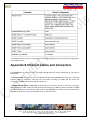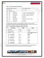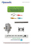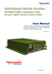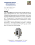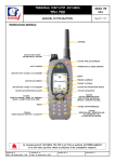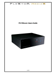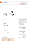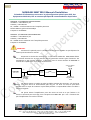
1
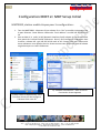
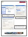
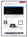
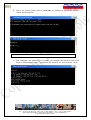
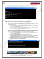
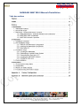
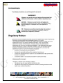
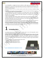
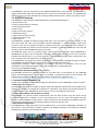
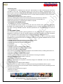
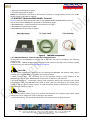
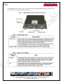
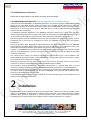
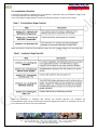
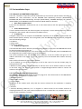
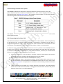
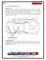
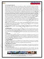
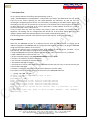
1
MOBIRAKE MMT 900.0 Manuel d’Installation Préambule d’informations concernant la préconfiguration spéciale pour SPIE, des équipements Mobirake, BTS et antenne spécifiques & recommandations impératives MBT9000 ‐ S/N MBT900.0JAA4A5526300DD IP address = 192.168.10.2 /24 Gateway = 192.168.10.1 RF = 20dBm – entrée maximum vers l’ampli de puissance Default GOS est gold. Gold est 2Mbps Frequence = 919.0MHZ MMT900 ‐ S/N MMT900.0JAA4A5496302B8 IP address = 192.168.10.3 /24 Gateway = 192.168.10.1 RF = 20dBm entrée maximum vers l’ampli de puissance Frequence = 919.0MHz ATTENTION: Attention à la polarité pour le raccordement à la source 12 Volts ne pas dépasser les valeurs prescrites dans le manuel. Respectez le schéma de montage car le transceiver Mobirake MMT 900.0 délivre une tension continue sur sa prise antenne pour la gestion de certains types d’antennes. Par conséquent ne pas omettre d’insérer le DC Block entre la sortie antenne du MMT900 et l’entrée de l’amplificateur sous peine de destruction. Antennex Mobile
Antenna
MMT/MBT
SMA Female
DC Block
N-male to SMA-Female
SMA-Male to
SMA-Male
RF Cable
N-male to
N-female
AMP
N- Female
N-female
N-Male to SMA Female
SMA Male to
Mag Mount RF
Cable
Ne jamais couper ou couder ou plier les câbles coaxiaux des antennes, si ils sont trop longs, leur faire suivre un cheminement plus long ou les lover en cercle le plus lâche possible avec le rayon de courbure le plus faible possible . Si impossibilité refaire un câble a la bonne longueur. Ne jamais utiliser l’amplificateur pour des essais en local et ne pas l’utiliser si la liaison ne nécessite pas son usage, il est transparent au MMT 900 qui « voit » l’antenne des que l’amplificateur est mis hors tension. M/M/D/S Hypercable® - 81 rue des Carrières - ZA de la Ronze 69440 - Taluyers - France
Tel: + 33 (0) 4 78 48 74 75 - Voip:+33 (0) 962 305 810 - Fax: + 33 (0) 426 031361
Mail: [email protected] - Web:www.hypercable.fr – www.worldwave.eu
– Code CEE: FR 19 384 007 894 –
2
Pour tests en local éloigner les équipements d’au moins 20 mètres, en 20dBm sans l’amplificateur se tenir au delà de 20cm de l’antenne, avec l’amplificateur se tenir au‐
delà de 1 mètre de l’antenne. (voir les normes de sécurité en annexe) Attention le rayonnement Radio en 919 Mhz avec l’ampli de puissance, peut perturber certains téléphones cellulaires GSM de mauvaise qualité, dans la bande 925 Mhz et uniquement à proximité très immédiate. Les réseaux ACROPOL SAPHIR et RUBIS ne sont en aucun cas perturbés. Attention le rayonnement Radio en 919 Mhz avec l’ampli de puissance peut dans certaines configurations perturber les CCD des Caméras les circuits électroniques et les ordinateurs dont les circuits ou les blindages ne seraient pas conformes aux normes CEM. L’antenne doit être sur un plan de sol métallique soit via sa base aimantée, soit boulonnée en traversée du métal. La surface métallique sous l’antenne ne peut être inférieure à l’équivalent d’une surface de 16 cm de diamètre afin d’obtenir gain et rayonnements comme ci‐dessous‐ (l’idéal est 1 mètre de diamètre en surface plane) M/M/D/S Hypercable® - 81 rue des Carrières - ZA de la Ronze 69440 - Taluyers - France
Tel: + 33 (0) 4 78 48 74 75 - Voip:+33 (0) 962 305 810 - Fax: + 33 (0) 426 031361
Mail: [email protected] - Web:www.hypercable.fr – www.worldwave.eu
– Code CEE: FR 19 384 007 894 –
3
Antenne Phantom® Lobes de rayonnement
Plan E Plan H Adaptation ROS et centrage sur la bande allouée M/M/D/S Hypercable® - 81 rue des Carrières - ZA de la Ronze 69440 - Taluyers - France
Tel: + 33 (0) 4 78 48 74 75 - Voip:+33 (0) 962 305 810 - Fax: + 33 (0) 426 031361
Mail: [email protected] - Web:www.hypercable.fr – www.worldwave.eu
– Code CEE: FR 19 384 007 894 –
4
MOBIRAKE MMT 900.0 Branchement & Câblage de l’alimentation. Câble d’alimentation Porte fusible Le porte fusible est fixé et raccordé à la Batterie du véhicule au pôle + 12volts Le fil rouge + 12 volts est serti au fil rouge du porte fusible Le fil noir est raccordé au Pole – 12 volts de la Batterie Le fil vert, prise de masse est raccordé au Châssis du véhicule Le fil blanc est raccordé a un Plus 12 VDC issu de la clef de contact ou d’un interrupteur spécifique raccordé au +12VDC afin de mettre le MMT en marche ( ou le mettre en parallèle avec le fil rouge) M/M/D/S Hypercable® - 81 rue des Carrières - ZA de la Ronze 69440 - Taluyers - France
Tel: + 33 (0) 4 78 48 74 75 - Voip:+33 (0) 962 305 810 - Fax: + 33 (0) 426 031361
Mail: [email protected] - Web:www.hypercable.fr – www.worldwave.eu
– Code CEE: FR 19 384 007 894 –
5
Configuration MMT et MBT Setup Initial MMT9000, station mobile étapes pour la configuration: 1. Tous les MMT9000’s disposent d’une adresse IP en “dur” accessible uniquement par le port Ethernet. Cette adresse référencée “local address” est 169.245.10.250 mask 16. 2. Pour accéder à la radio, le NIC (Network Interface Card) adresse de l’ordinateur doit faire partie de la même famille d’adresses. Donc il faut configurer l’ordinateur dans la même adresse NIC soit 169.245.10.10 mask of 16. Compte tenu que l’adresse de votre ordinateur sera diffusée dans le réseau assurez vous que votre choix d’adresse ne générera pas un conflit d’adresses. b) “Network Connections” dans ce cas ou Connection réseau apparait a) Selon votre OS Sélectionnez votre interface réseau afin de configurer l’adresse IP de votre PC M/M/D/S Hypercable® - 81 rue des Carrières - ZA de la Ronze 69440 - Taluyers - France
Tel: + 33 (0) 4 78 48 74 75 - Voip:+33 (0) 962 305 810 - Fax: + 33 (0) 426 031361
Mail: [email protected] - Web:www.hypercable.fr – www.worldwave.eu
– Code CEE: FR 19 384 007 894 –
6
c) dans ce cas clic gauche de la souris sur “Local Area Connection”, permet de sélectionner “Properties”. Propriétés d) Sélectionner “Internet Protocol (TCP/IP)”. Ensuite cliquer “Properties” Propriétés ouvre la fenêtre suivante. e) Entrer 169.254.10.10 dans le champ “IP address:”. Le masque de sous réseau, cliqué se configure automatiquement comme ci‐dessus , cliquer“OK” pour sauver la configuration. M/M/D/S Hypercable® - 81 rue des Carrières - ZA de la Ronze 69440 - Taluyers - France
Tel: + 33 (0) 4 78 48 74 75 - Voip:+33 (0) 962 305 810 - Fax: + 33 (0) 426 031361
Mail: [email protected] - Web:www.hypercable.fr – www.worldwave.eu
– Code CEE: FR 19 384 007 894 –
7
3. Ouvrir ensuite une fenêtre MSDOS window. Aller sur “start” sélectionnez “Run” et une fenêtre “Run” s’ouvre. Entrer “cmd” pour ouvrir une fenêtre de commandes MSDOS. Cliquer OK pour avoir accès a la rédaction des commandes. M/M/D/S Hypercable® - 81 rue des Carrières - ZA de la Ronze 69440 - Taluyers - France
Tel: + 33 (0) 4 78 48 74 75 - Voip:+33 (0) 962 305 810 - Fax: + 33 (0) 426 031361
Mail: [email protected] - Web:www.hypercable.fr – www.worldwave.eu
– Code CEE: FR 19 384 007 894 –
8
4. Dans la fenêtre MSDOS entrer “ipconfig” afin de vous assurer que votre PC à bien accepté la configuration et que votre cartre réseau « NIC card » est configurée en 169.254.10.250 mask of 16 (255.255.0.0) 5. Connecter une antenne ou une charge fictive a la prise antenne du MMT900. 6. Utiliser une alimentation externe 12 VDC régulée pour l’alimenter en raccordant le fil rouge et le fil blanc sur le +12Volts DC et le fil Noir et vert sur le 6 12 volts DC de l’alimentation. 7. Raccorder le port Ethernet de l’ordinateur à la prise Ethernet du MMT avec un câble RJ 45 croisé. DC Power Supply set
to 12VDC
Laptop computer
Ethernet X-over Cable
18-ft 4 - Pin Conxall Cable
Connect red and white
wires to + side of power
supply
Connect green and black
wires to - side of power
supply.
M/M/D/S Hypercable® - 81 rue des Carrières - ZA de la Ronze 69440 - Taluyers - France
Tel: + 33 (0) 4 78 48 74 75 - Voip:+33 (0) 962 305 810 - Fax: + 33 (0) 426 031361
Mail: [email protected] - Web:www.hypercable.fr – www.worldwave.eu
– Code CEE: FR 19 384 007 894 –
9
8. Ouvrir une session Telnet avec le MMT9000, en utilisant la commande MSDOS : “telnet 169.254.10.250” Lorsque “Password” s’affiche presser la touche “enter” Entrée pour vous connecter.
9. Pour configurer une adresse IP sur le MMT, par exemple 192.168.10.3 mask of 24 entrer la commande suivante : “ip ethernet 192.168.10.3 24”, ensuite entrer “save”. M/M/D/S Hypercable® - 81 rue des Carrières - ZA de la Ronze 69440 - Taluyers - France
Tel: + 33 (0) 4 78 48 74 75 - Voip:+33 (0) 962 305 810 - Fax: + 33 (0) 426 031361
Mail: [email protected] - Web:www.hypercable.fr – www.worldwave.eu
– Code CEE: FR 19 384 007 894 –
10
10. Pour configurer IP gateway sur le MMT pour 192.168.10.1 entrer la commande suivante : “ip gateway 192.168.10.1”, ensuite entrer “save”. 11. Pour régler la fréquence sur le MMT pour 919.0MHz entrer la commande suivante: “radio frequency 9190”, ensuite entrer “save”. 12. Pour régler la puissance par exemple 20dBm entrer la commande suivante: “radio rf 20”, ensuite entrer “save”.
13. Pour que ces réglages soient appliqués et effectifs, un “reboot” est nécessaire. Pour faire un “reboot” du MMT, entrer la commande “reboot”. M/M/D/S Hypercable® - 81 rue des Carrières - ZA de la Ronze 69440 - Taluyers - France
Tel: + 33 (0) 4 78 48 74 75 - Voip:+33 (0) 962 305 810 - Fax: + 33 (0) 426 031361
Mail: [email protected] - Web:www.hypercable.fr – www.worldwave.eu
– Code CEE: FR 19 384 007 894 –
11
1. Pour vérifier les paramètres de configuration du MMT revenir en connexion telnet sur le
MMT et entrer la commande “ip” et la commande ‘’ra’’ “radio”.
MBT9000 Station de Base, étapes de configuration: 2. Pour connecter et configurer la MBT 9000( station de base) , répéter les étapes 5 à 12 avec les exceptions suivantes : a. A l’etape 6 l’adresss locale de la MBT est 169.254.10.249. Donc la commande telnet sera “telnet 169.254.10.249”. b. A l’étape 7 l’adresse de la MBT est 192.168.10.2 mask of 24, la commande suivante sera “ ip ethernet 192.168.10.2 24” ensuite entrer ‘’save’’. 3. La MBT sera configurée pour utiliser le GOS gold. Ce GOS à été spécialement modifié pour délivrer un débit utile allant de 0 to 2Mbps. D’usine et par défaut , le gold GOS est ajusté pour 256kbp à 512kbps. Pour modifier le gold GOS suivre les étapes suivantes: a. Le logiciel “CCU3100 GOS Library” vous est fourni par Hypercable placez le sur le ‘’bureau’’ de votre ordinateur. b. Ouvrir une fenêtre MSDOS window comme expliqué à l’étape 3. c. Changer le “directory” repertoire du bureau du PC. La commande est “cd desktop”. Vous remarquerez la réponse changera pour inclure “desktop” "le bureau". d. Dézziper la librairie GOS et extraire le GOS ci après en le plaçant sur le bureau “Normal User” directory, gos0‐2000N0‐1430.cfg. M/M/D/S Hypercable® - 81 rue des Carrières - ZA de la Ronze 69440 - Taluyers - France
Tel: + 33 (0) 4 78 48 74 75 - Voip:+33 (0) 962 305 810 - Fax: + 33 (0) 426 031361
Mail: [email protected] - Web:www.hypercable.fr – www.worldwave.eu
– Code CEE: FR 19 384 007 894 –
12
e. Ouvrir une session FTP avec la MBT à l’aide de la commande suivante : “ftp 169.254.10.249”, presser la touche “enter” entrée pour le ‘’username’’ et le ‘’password’’. f. Entrer les commandes FTB suivantes suivies par la touche “enter” “entrée”, “ha” et “bin”. g. Pour télécharger le nouveau fichier GOS pour gold entrer la commande suivante: “put gos0‐2000N0‐1430.cfg gosgold.cfg” ensuite taper “enter” ‘’Entrée’’ pour éxécuter la commande. Si le transfert est réussi le message suivant est affiché “Transfered “gosgold.cfg” Okay” h. Pour terminer la session entrer “bye” M/M/D/S Hypercable® - 81 rue des Carrières - ZA de la Ronze 69440 - Taluyers - France
Tel: + 33 (0) 4 78 48 74 75 - Voip:+33 (0) 962 305 810 - Fax: + 33 (0) 426 031361
Mail: [email protected] - Web:www.hypercable.fr – www.worldwave.eu
– Code CEE: FR 19 384 007 894 –
13
4. Ouvrir une nouvelle fenêtre MSDOS et ouvrir une session telnet avec la MBT. Dès que connecté , lancer la commande suivante, “auth gos gold”. Pour confirmer que le GOS gold est 0 à 2Mbps aller à la colonne “active (kbps)” de la ligne “ideal:” qui confirme (14) et “min:” est (2000). 5. Par défaut le GOS est bronze et est de 0 to 1Mbps. Pour changer le GOS par défaut en gold, entrer la commande suivante “auth def gold”, et ensuite “save”. M/M/D/S Hypercable® - 81 rue des Carrières - ZA de la Ronze 69440 - Taluyers - France
Tel: + 33 (0) 4 78 48 74 75 - Voip:+33 (0) 962 305 810 - Fax: + 33 (0) 426 031361
Mail: [email protected] - Web:www.hypercable.fr – www.worldwave.eu
– Code CEE: FR 19 384 007 894 –
14
MOBIRAKE MMT 900.0 Manuel d’Installation Table des matières M/M/D/S Hypercable® - 81 rue des Carrières - ZA de la Ronze 69440 - Taluyers - France
Tel: + 33 (0) 4 78 48 74 75 - Voip:+33 (0) 962 305 810 - Fax: + 33 (0) 426 031361
Mail: [email protected] - Web:www.hypercable.fr – www.worldwave.eu
– Code CEE: FR 19 384 007 894 –
15
M/M/D/S Hypercable® - 81 rue des Carrières - ZA de la Ronze 69440 - Taluyers - France
Tel: + 33 (0) 4 78 48 74 75 - Voip:+33 (0) 962 305 810 - Fax: + 33 (0) 426 031361
Mail: [email protected] - Web:www.hypercable.fr – www.worldwave.eu
– Code CEE: FR 19 384 007 894 –
16
M/M/D/S Hypercable® - 81 rue des Carrières - ZA de la Ronze 69440 - Taluyers - France
Tel: + 33 (0) 4 78 48 74 75 - Voip:+33 (0) 962 305 810 - Fax: + 33 (0) 426 031361
Mail: [email protected] - Web:www.hypercable.fr – www.worldwave.eu
– Code CEE: FR 19 384 007 894 –
17
Warnings and Advisories General Advisory Installers, operators and maintenance personnel must be familiar with the related safety requirements before they attempt to install or operate the MMT900. It is the responsibility of the operator to ensure that the public is not exposed to excessive Radio Frequency (RF) levels. The applicable regulations can be obtained from local authorities. WARNING! To comply with FCC RF exposure limits, the MMT900 mobile antennas must be mounted to provide a separation distance of 20cm or more from all persons. The MMT900 panel r Yagui antenna must be mounted to provide a separation distance of 30cm or more from all persons. Thedistance is measured from the nearest point of the antenna to the human body. WARNING! The MMT900 is only to be installed by qualified professional installers, who are familiar FCC regulations and with installing radio transmission equipment, especially in vehicles. The installer must be familiar with all. 1. Read all these instructions before installing and operating the MMT900. 2. Retain these instructions for future reference. 3. Heed all warnings on the MMT900 and in these instructions. 4. Follow all instructions. 5. Disconnect MMT900 from its power source before cleaning. Clean only with a damp cloth. 6. Use only attachments recommended by Hypercable. 7. The metal housing protects the MMT900 from overheating to ensure reliable operations. Do not cover the MMT900. Although the MMT900 has been rated for a wide range of temperatures, it will perform better and longer if proper ventilation is provided. 8. Operate the MMT900 only from a DC power supply, such as a standard vehicle power system, within the DC power supply range stated in the technical specifications. Using other voltages or AC power can result in damage to the MMT900. 9. Use the fuse assembly provided to protect the MMT900 from power surges in the vehicle power system as well as protecting the power system from short circuits in the MMT900 or its power cable. 10. Route the Power‐supply cable, Ethernet cable and Antenna cable so that they are not likely to be walked on or pinched by items placed upon or against them, paying particular attention to cord and cables at their plugs, convenience receptacles and the points where the cords exit the equipment. 11. Provide strain relief for cables near their connections. This is typically done by leaving a loop in the cable near the connection. 12. Do not locate the MMT900 in the vicinity of power lines or other electric light or power circuits, or where it can fall onto such power lines or circuits. 13. For added protection during a lightning storm, or when it is left unattended and unused for long periods of time, unplug the MMT900. This will power down the MMT900. 14. Never push foreign objects of any kind through openings (e.g. Ethernet jack) in this wireless product as they may short‐out parts that could result in a fire or electric shock and damage the unit. M/M/D/S Hypercable® - 81 rue des Carrières - ZA de la Ronze 69440 - Taluyers - France
Tel: + 33 (0) 4 78 48 74 75 - Voip:+33 (0) 962 305 810 - Fax: + 33 (0) 426 031361
Mail: [email protected] - Web:www.hypercable.fr – www.worldwave.eu
– Code CEE: FR 19 384 007 894 –
18
15. The MMT900 is a rugged unit that can tolerate a wide range of environments if installed correctly, but it is not rated as being submersible nor immune to all liquids from all directions. If the MMT900 may experience rain, then mount the unit so that the rain does not fall on or drip directly onto the connector endplate. 16. Do not attempt to service this wireless product yourself. Refer all servicing to qualified service personnel. 17. Unplug the unit and refer servicing to qualified service personnel under the following conditions: • When the power supply cord or plug is damaged. • If the MMT900 does not operate normally for an extended period of time when following the operating instructions. Note that it is possible that Internet traffic can be slow even under normal operations due to network congestion and radio interference and fading and not as result of problems with the MMT900. • When the MMT900 exhibits distinct changes in performance. This may indicate a need for service. 18. When replacement parts are required, be sure the service technician has used replacement parts specified by Hypercable or with the same characteristics as the original part. Improper substitutions may result in fire, electric shock or other hazards. 19. Upon completion of any service or repairs to this wireless product, ask the service technician to perform safety checks to determine that the wireless product is in proper operating condition. 20. Install the MMT900 in compliance with local and national electrical codes where applicable. The following are the national codes. The installer is responsible for knowing the appropriate local codes. • In Europe use the CE and CEM recommendations and in other countries, use International Electrotechnical Commission (IEC) 364, part 1 through 7. 1 Introduction The Mobirake WAN family of wireless systems enables mobile, secure, field deployable wireless access networking and operates in the 900 MHz ISM band. The Mobirake WAN consists of a base station and a mix of multiple fixed subscriber terminals and mobile subscriber terminals. The Mobirake WAN system comes fully configured as a basic system to provide high‐speed data services. With optional components, the Mobirake WAN has the capability to provide enhanced telephone service via an IP PBX, as well as security video and short message text services. The system connects to all standard IP and telephony networks using standard interface protocols. The basic components of the Mobirake WAN system include: 1. MBT9000 ‐ Mobirake WAN Base Terminal 2. MFT9000 ‐ Mobirake WAN Fixed Terminal 3. MMT900 ‐ Mobirake WAN Mobile Terminal Figure 1 MMT900 Mobirake WAN Mobile Terminal M/M/D/S Hypercable® - 81 rue des Carrières - ZA de la Ronze 69440 - Taluyers - France
Tel: + 33 (0) 4 78 48 74 75 - Voip:+33 (0) 962 305 810 - Fax: + 33 (0) 426 031361
Mail: [email protected] - Web:www.hypercable.fr – www.worldwave.eu
– Code CEE: FR 19 384 007 894 –
19
The MMT900 is the first component of the MobirakeWAN family to be released. The MMT900 is a rugged vehicle data‐radio that provides Ethernet access to the IP‐based internet. The MMT900 has been designed to be easily installed into a vehicle and be powered from a vehicle's DC power system. 1.1 MMT900 Features The MMT900 is well suited for mobile applications in the following industries: • remote works sites, • private communications networks, • municipal governments, • public works, • large construction projects, • homeland security, • public safety (non life‐critical), • industrial solutions, and • special events. The MMT900 is capable of delivering high‐speed data, voice, and video over a secure airlink. It can work with VPNs and other security middle ware.The MMT900 is a mobile wireless modem that connects to the user's computer through an Ethernet connection. It is intended to be installed in a vehicle and provides an interface to the customer's computer or local area network on one side and wireless access to the LMS4000 network on the other. The MMT900, which acts as a network bridge, receives data from the Base Station (MBT9000 or LMS4000 CCU or NCL)1 over the 900 MHz radio link, and forwards this data to the user's computer through the Ethernet port. In the other direction, the MMT900 forwards data received from the user's computer over the radio link to the Base Station. The MMT900 has a compact form factor designed for use in a vehicle, including emergency vehicles. The MMT900 has outstanding RF performance in a hostile mobile environment. Temperature, vibration, shock, exposure to moisture and ease of installation have all been considered in the modem packaging. Set‐up and configuration is rapid and simple. Features of the MMT900 include: • Nomadic Base Station Discovery (factory default) – The MMT900 searches all available channels or channels from a user‐defined list. The MMT900 selects which Base Station or access point to establish a connection based on airlink quality and authorization acceptance. With this and DCHP Client enabled (factory defaults), the 1. We will use the generic term “Base Station” throughout this document to stand for any of 900 Mhz base station products. 1: Introduction APCD‐WM001‐1.3 3 installer does not need to enter ANY configuration parameters into the MMT900 in order to install it. • DHCP Client (factory default)‐ The MMT900 can obtain its IP address, subnet mask and IP gateway information from a DHCP server, reducing the amount of configuration required for installation. This allows the network operator to reassign IP addresses to MMT900s without having to access the mobile terminal itself. • Secure Authentication and User Data Encryption: The MMT900 can perform mutual authentication with the Base Station using the secure 4‐way handshake mechanism of WPA2. All user data flowing over the air can be encrypted using the industry standard IEEE802.11 TKIP cypher. Traffic to and from each terminal is encrypted using a key specific to that terminal, ensuring message integrity and privacy for each user. • Auto Remote Configuration – The MMT900 will accept parameters from a RADIUS server to set other configurable parameters in the modem. These parameters include: password, all SNMP parameters, RF Frequency (including enabling auto‐discovery), and number of hosts. M/M/D/S Hypercable® - 81 rue des Carrières - ZA de la Ronze 69440 - Taluyers - France
Tel: + 33 (0) 4 78 48 74 75 - Voip:+33 (0) 962 305 810 - Fax: + 33 (0) 426 031361
Mail: [email protected] - Web:www.hypercable.fr – www.worldwave.eu
– Code CEE: FR 19 384 007 894 –
20
• Monitoring Tools – The MMT900 has a Windows GUI, LEDs and a SETUP Menu to make monitoring the airlink very accessible to the user. The MMT900 supports the local link IP address, 169.254.10.250, on its Ethernet port at all times. Using the local link address, the user can use the password “setup” at any time to call up the setup menu that allows any user to check the RF link quality to verify connectivity. • Mobile and Fixed Antennas ‐ The MMT900 is certified to work with a variety of antennas, including whip antennas that can be permanently mounted on a vehicle or magnetically mounted and a high‐gain panel antenna that can be mounted on a mobile command center or permanently installed as required. • Interoperable with LMS4000 System – The MMT900 can connect to the MBT9000 or any LMS4000 Base Station product. It can also share the network with a mixture of MMT900s, MFT9000s, and residential EUMs. Thus the MMT900 can use a network designed exclusively for its use and/or existing LMS4000 networks. Detailed specifications for the MMT900 can be found on demand. 1.2 Document Scope This installation guide provides general guidelines for the installation and configuration of the MMT900, its performance, and any required regulatory information, including approved installation notices. The Setup menu is described, which can be used to align the MMT900 antennas. The concepts for the MobirakeWAN family of components are the same as the fixed wireless LMS4000 family. Related information can be found in the suite of available LMS4000 manuals, which includes the following: • LMS4000 900 MHz Radio Networking Concepts (APCD‐LM053) • LMS4000 Data Networking Concepts (APCD‐LM050) • LMS4000 Managing the Network (APCD‐LM052) 1: Introduction APCD‐WM001‐1.3 4 • LMS4000 CLI Reference Manual (APCD‐LM051) • LMS4000 SNMP Reference Manual (APCD‐LM049) • Acronyms and Glossary (APCD‐LM056) These manuals provide information not included in this Installation Guide, including information on: • Planning, installing and managing the network. • Diagnostic tools for the network and modems. • Details on the Command Line Interface and methods of accessing the modems. • Manual configuration of the modem via the CLI. • Glossary of network terms. These manuals can be found on demand NOTE: The installer may be required to manually configure the MMT900. In this case, the installer should be familiar with LMS4000 CLI Reference Manual (APCD‐LM051). Other documents are useful to assist in installing and operating the MMT900 cellular system. Hypercable recommends that you be familiar with the following sections before proceeding with the instructions in this guide: • Software License Agreement on page iii • Warranty on page iv • Conventions on page viii M/M/D/S Hypercable® - 81 rue des Carrières - ZA de la Ronze 69440 - Taluyers - France
Tel: + 33 (0) 4 78 48 74 75 - Voip:+33 (0) 962 305 810 - Fax: + 33 (0) 426 031361
Mail: [email protected] - Web:www.hypercable.fr – www.worldwave.eu
– Code CEE: FR 19 384 007 894 –
21
• Warnings and Advisories on page x • Important Safeguards on page x NOTE: The information contained in this manual is subject to change without notice. The reader should consult hypercable for updates. 1.3 MMT900 ‐ MobirakeWAN Mobile Terminal Figure 2 shows the components that make up the MMT900 MobirakeWAN Mobile Terminal. Key elements of the MMT900 are described on the following pages: • MMT900 Modem ‐ External Indicators and Connectors on page 5 • MMT900 Suite of Antennas on page 7 • MMT900 Nomadic Operation on page 9 1.3.1 MMT900 Modem ‐ External Indicators and Connectors All interfaces on the MMT900 are on one side of the radio for ease of installation. The following interfaces are: • Ethernet port ‐ 10BaseT RJ45 receptacle to connect the modem to the end‐user’s computer. Details on the Ethernet port are found in Appendix B on page 29. CAUTION: Any DC voltage applied to the Ethernet port may damage the MMT900, the Ethernet cable, and/or network gear. The MMT900 is not a Power‐over‐Ethernet device. • SMA‐F Antenna Port ‐ for connecting one of the approved mobile or fixed antennas to the MMT900. See section 1.3.2, MMT900 Suite of Antennas for details on the antennas. • DC Power Connector ‐ a watertight, locking 4 pin receptacle receives the connector from vehicle power system cable. The MMT900 comes with an 18‐ft. cable for connecting to the vehicle power system as well as a fuse assembly. The pin out and connection details are discussed in Connecting to Vehicle Power System on page 14. CAUTION: Use standard vehicle power system. See technical specifications for maximum input power supply voltage. Any other voltage can result in damage to the modem. • Chassis Ground Lug ‐ this should be connected to the vehicle chassis or ground system. M/M/D/S Hypercable® - 81 rue des Carrières - ZA de la Ronze 69440 - Taluyers - France
Tel: + 33 (0) 4 78 48 74 75 - Voip:+33 (0) 962 305 810 - Fax: + 33 (0) 426 031361
Mail: [email protected] - Web:www.hypercable.fr – www.worldwave.eu
– Code CEE: FR 19 384 007 894 –
22
The MMT900 also has 3 LEDs. Figure 3 shows the layout of the MMT900 Connectors and LEDs, while Table 1 and Table 2 explain what each LED means. M/M/D/S Hypercable® - 81 rue des Carrières - ZA de la Ronze 69440 - Taluyers - France
Tel: + 33 (0) 4 78 48 74 75 - Voip:+33 (0) 962 305 810 - Fax: + 33 (0) 426 031361
Mail: [email protected] - Web:www.hypercable.fr – www.worldwave.eu
– Code CEE: FR 19 384 007 894 –
23
1.3.2 MMT900 Suite of Antennas: Please Ask to Hypercable for the better and safe antenna design. 1.3.3 MMT900 Nomadic Operation ( Not full applicable for SPIE system design) A key feature of the MMT900 is its Nomadic Operations. This feature allows the MMT900 to quickly search for the best Base Station. Should the signal from theBase Station become too poor, the MMT900 re‐searches for the next Base Station. In this way, the MMT900 is never out of touch with a Base Station for more than a few seconds, provided that it is moving around within the coverage areas of several base stations. To implement Nomadic Operations, the MMT900 constantly monitors the signal from the Base Station. When the packet error rate goes above 15% for 15 seconds, the MMT900 searches through a list of frequencies and registers with the “best” Base Station that will allow it to register. The factory default is for the MMT900 to search all 101 frequencies. To speed up the search, a list of frequencies to be used can be configured to force the MMT900 to search only the relevant frequencies. Care must be taken when designing an LMS network that will support nomadic units. If an MMT900 moves between two Base Station that support the same IP subnet (i.e. are in switched mode on the same Ethernet broadcast domain) then service will continue nearly uninterrupted. However, if an MMT900 moves between two Base Station supporting separate IP subnets (routed mode or separate domains), then the end‐user’s PC(s) will have to have new IP addresses, by DHCP or mobile IP protocols. The “break‐on‐line” feature can assist in triggering the end‐user PC to get a new IP address. This feature disables the Ethernet port on the MMT900 for a configurable period of time when a search for a new base station frequency is started. Disabling the Ethernet port for long enough forces most current operating systems on the user's computer to request a new IP address, gateway and DNS servers via DHCP. For computers running Windows XP, Hypercable recommends a 7 second break time. Use the command “rad freq nomadic 7” to set the MMT900 to nomadic mode with a 7 second break time. The “break‐on‐line” feature only works if the PC is directly connected to the MMT900 Ethernet port. If a hub or switch is placed between the PC and the MMT900, the PC will not lose its Ethernet link, since that is provided by the hub or switch. If the MMT900 itself has its DHCP client enabled, then it will use DHCP to get a new IP address for the modem when it changes Base Stations. 2 Installation The MMT900 must be installed by a professional installer who is familiar with the CE regulations that apply to the MMT900. Familiarity with installing vehicle‐mounted 2‐way radio equipment is highly desirable. Best practices applicable to vehicle mounted radio systems should be followed for providing power and grounding to the modem as well as antenna placement on a vehicle. M/M/D/S Hypercable® - 81 rue des Carrières - ZA de la Ronze 69440 - Taluyers - France
Tel: + 33 (0) 4 78 48 74 75 - Voip:+33 (0) 962 305 810 - Fax: + 33 (0) 426 031361
Mail: [email protected] - Web:www.hypercable.fr – www.worldwave.eu
– Code CEE: FR 19 384 007 894 –
24
2.1 Installation Checklist A successful installation is divided into pre‐installation, installation and post‐installation stages, with each stage outlined in the following checklists. The Pre‐Installation Stage Checklist involves the Network Operator as well as the installer. When everything is ready for the installation stage, then the installer performs the following steps: Once the installation is complete and verified, the network operator can complete the Postinstallation Stage, using the Automatic Remote Configuration feature or manually over the air. This is discussed in section 2.4, Post‐Installation M/M/D/S Hypercable® - 81 rue des Carrières - ZA de la Ronze 69440 - Taluyers - France
Tel: + 33 (0) 4 78 48 74 75 - Voip:+33 (0) 962 305 810 - Fax: + 33 (0) 426 031361
Mail: [email protected] - Web:www.hypercable.fr – www.worldwave.eu
– Code CEE: FR 19 384 007 894 –
25
2.2 Pre‐Installation Steps 2.2.1 Network and MMT900 Configuration There are a number of steps that must be undertaken by the network operator before installing an MMT900. For more information, see the LMS4000 Data Networking Concepts (APCDLM050), LMS4000 900 MHz Radio Networking Concepts (APCD‐LM053), LMS4000 Managing the Network (APCD‐LM052), and LMS4000 CLI Reference Manual (APCD‐LM051)on demand. 1. Base Station Authorization: Ensure that the MMT900 is authorized at one or more Base Stations with the appropriate Grade of Service. 2. Secure Authentication: If secure authentication and user data encryption are required, a secret authentication key must be configured in the terminal and base station (or RADIUS server). 3. IP Addresses: Configure a DHCP server to accept the new MMT900’s request(s) for an IP address, if the modem has DHCP enabled (factory default). If not using DHCP, then the MMT900 must be manually configured with the following settings: • IP address • Subnet mask • Gateway IP address 4. Frequency Assignment: If the Nomadic Base Station Discovery feature (factory default) is used, then the MMT900 will search for the Base Station upon power up. This is the recommended approach. If for some reason this is not acceptable, then the MMT900 must be configured with its radio frequency or list of frequencies. The easiest installation uses the MMT900 factory defaults, so that the modem will gets all its IP address information from DHCP and its RF Frequency from the Nomadic Base Station Discovery feature. Other useful information for the installer includes: • The IP address of a site that accepts pings as well as the name of a site that accepts pings, for testing the data link. • Whether modem is being connected directly to end‐user PC or via an Ethernet switch or IP router. In the latter cases, the installer must provide a straight‐through Ethernet cable to connect the modem to the switch/router. 2.2.2 Verifying the MMT900 Components See MMT900 ‐ MobirakeWAN Mobile Terminal on page 4 for more information on the MMT900 kit. Verify that the MMT900 kit is complete with: • MMT900 modem • Power cable assembly • Fuse assembly In addition to the modem itself, verify that the antenna selected for the installation is complete, including: • Antenna • Antenna Mounting hardware, be it a magnetic or vehicle mount for the mobile antennas or clamping hardware for the panel antenna Equipment that is needed but not provided since it will unique to each installation, includes: M/M/D/S Hypercable® - 81 rue des Carrières - ZA de la Ronze 69440 - Taluyers - France
Tel: + 33 (0) 4 78 48 74 75 - Voip:+33 (0) 962 305 810 - Fax: + 33 (0) 426 031361
Mail: [email protected] - Web:www.hypercable.fr – www.worldwave.eu
– Code CEE: FR 19 384 007 894 –
26
• Ethernet cable ‐ this will be a straight‐through or cross‐over cable depending on whether the end‐user’s PC is connected to a switch or directly to the MMT900. • Mounting bolts, washers and nuts ‐ for attaching the MMT900 rail to an equipment tray, directly to the vehicle or to some other attachment point. 2.2.3 End‐Users PC Ensure that the end‐user PC is equipped with an Ethernet interface. 2.3 Installation Steps 2.3.1 Locating the MMT900 The MMT900 has been designed and tested for a rugged mobile environment. It is designed to meet IP53 rating (dust protected, light rain), so an additional enclosure to house the modem is not required. The MMT900 can be installed in the trunk area or in the passenger compartment of the vehicle. Do not install in the engine compartment. The location of the MMT900 in a vehicle should be close as possible to the mobile antenna to reduce cable insertion loss. Other possible locations for the MMT900 are. under the driver or passenger seat, trunk side panel or trunk floor. CAUTION: If the MMT900 is likely to be exposed to rain or spray, orient the MMT900 so that the connector endplate is more protected.This can be achieved by having the connectors facing down or facing away from the exposed side. All connectors except the Ethernet connector are waterproof. If the Ethernet connector is subjected to too much spray, it can leak and/or short out until dry. Ensure the boot of the Ethernet cable is snug against the chassis. M/M/D/S Hypercable® - 81 rue des Carrières - ZA de la Ronze 69440 - Taluyers - France
Tel: + 33 (0) 4 78 48 74 75 - Voip:+33 (0) 962 305 810 - Fax: + 33 (0) 426 031361
Mail: [email protected] - Web:www.hypercable.fr – www.worldwave.eu
– Code CEE: FR 19 384 007 894 –
27
2.3.2 Connecting to Vehicle Power System The MMT900 is designed to work directly from the vehicle DC electrical system or from a DC power distribution panel. Included in the MMT900 kit is an 18‐ft., 4‐wire, 18‐gauge cable with an 2‐
amp inline fuse kit (see Figure 2 on page 5). The connector to the modem is a twist‐lock assembly. The following table shows the wire color and its purpose: The MMT900 also has a ground lug on the connector endplate which should be connected to the vehicle ground system. 2.3.3 Connecting the End‐User’s PC The Ethernet interface on the MMT900 is a 10BaseT Ethernet RJ‐45 receptacle. If connecting directly to the end‐user’s PC, a crossover cable is required. If connecting to an Ethernet hub or switch, a straight‐through Ethernet cable is used. The Ethernet cable must be able to withstand the same environment as the MMT900, so cable rated as CAT5 outdoor or better is recommended An Ethernet surge suppressor should be connected as close as possible to the MMT900 Ethernet interface. This suppressor must be connected to the chassis ground. As noted, there are many ways to connect the MMT900 to the end‐user’s PC, using Ethernet switches, IP routers, etc. The discussion below is for the simplest, most direct method of connection. 1. Connect the end‐user’s PC by attaching a crossover Ethernet cable between the Ethernet port on the end‐user’s computer and the Ethernet port on the modem. 2. Apply power and wait 10 seconds for the MMT900 to come up. 3. Check the Ethernet LEDs on the Ethernet interface of the modem and/or end‐user’s PC to ensure the Ethernet connection between the MMT900 and the end‐user’s PC is active. Refer to Table 1 on page 6 for an explanation of the Ethernet LEDs normally provided on Ethernet interface cards. 4. When attempting to send data to, or receive data from, the Internet, check the Ethernet Traffic LED to ensure data transmission is taking place. This LED flashes as data traffic passes between the end‐user’s PC and the MMT900 M/M/D/S Hypercable® - 81 rue des Carrières - ZA de la Ronze 69440 - Taluyers - France
Tel: + 33 (0) 4 78 48 74 75 - Voip:+33 (0) 962 305 810 - Fax: + 33 (0) 426 031361
Mail: [email protected] - Web:www.hypercable.fr – www.worldwave.eu
– Code CEE: FR 19 384 007 894 –
28
2.3.4 Locating the MMT900 Antenna Mobile Antenna The mobile antennas for the MMT900 should be mounted on the top of the vehicle or in the middle of the trunk lid. These locations provide good unobstructed locations that are at least 20 cm away from people. Hypercable also recommends that the MMT900 antenna be mounted away from other radio system antennas to reduce possible interference between systems. These guidelines apply to both fixed and magnetic mount mobile antennas. The magnetic mount antennas are intended to be put into position when the vehicle has stopped. The magnet may not hold when the vehicle is moving. Panel or Yagui Antenna: The MMT900 panel antenna is intended for outdoor installation, either in a permanent or semi‐
permanent (e.g. on the top of a mobile command centre vehicle that is usually left in place for many hours or days). The major difference is that the antenna in a semi‐permanent location must be re‐
adjusted for each new location.
M/M/D/S Hypercable® - 81 rue des Carrières - ZA de la Ronze 69440 - Taluyers - France
Tel: + 33 (0) 4 78 48 74 75 - Voip:+33 (0) 962 305 810 - Fax: + 33 (0) 426 031361
Mail: [email protected] - Web:www.hypercable.fr – www.worldwave.eu
– Code CEE: FR 19 384 007 894 –
29
2.3.5 Testing the Data Link Omni‐directional Mobile Antennas are designed to capture radio signals from any direction. Repositioning the antenna (or vehicle) may be needed if the signal levels are not adequate in a given location. Generally, it is better to have the antenna as high as possible. Also the further away from surfaces that can reflect the radio waves the better, so parking away from buildings is usually better. When using the panel antenna at a new location, be sure to orient the antenna so that it is pointing at the best signal. Use the Radio LED to help in positioning or orienting the antenna. The Radio LED will flash more quickly if the signal improves. If the Radio LED does not flash at all, then there is no radio signal in that position or orientation. Alternatively, the Setup Menu as described in section 3, Setup Menu provides the figures of merit for the signal. The goal for a good installation is to have the Signal Strength FOM in the range of 5‐8 and the Signal Quality FOM to be in the range 4‐5. However, there are many good installations with lower figures of merit. Using the LEDs or Setup Menu, you can determine if the location has adequate figures of merit. MMT900. In most cases, a signal strength of 5 with a signal quality of 4 is a better signal that a signal strength of 6 and signal quality of 2. The following are simple tests that the installer or end‐user can perform to ensure that the link is functioning correctly. These tests may be used for each new location, especially if the link does not appear to be working as expected. If any test fails, then the subsequent tests are likely to fail as well until the problem is resolved NOTE: Turn off all cordless phones in the customer’s premises, and any other equipment that uses the 900MHz ISM band. Once the installation is complete, turn this equipment back on and monitor for interference or degraded signal quality. 1. Ping the MMT900: Configure the end‐user’s PC to have an IP address on subnet 169.254.x.x and ping the MMT900 at IP address “169.254.10.250” (see Ping the MMT900 on page 17 for more details if needed). 2. Assess the Link: Use the Setup Menu as described in Setup Menu on page 21 to assess the Radio Link Status and to get the Troubleshooting information to baseline the installation. This test verifies that the end‐user’s PC is communicating with the MMT900 and provides insight into the state of the RF link. This test is recommended since it provides details on the state of the modem and what Base Station(s) it has located. 3. Verify DHCP: If the network assigns end‐user PC’s IP addresses by DHCP, then reconfigure the end‐user PC to use DHCP to automatically obtain its IP address. Verify the end‐user PC has received an IP address, by using the DOS command “ipconfig” and seeing that an IP address is assigned along with Gateway and DNS server addresses This confirms that the End user PC is contacting the DHCP server correctly.See Verify DHCP on page 18 if more details are required. 4. Ping the Gateway: Assuming the end‐user PC has an IP address and a Gateway address as shown by the “ipconfig” command, ping the gateway to determine if it can be reached. See Ping the Gateway on page 18 if more details are required. This step assume your gateway will respond to pings. 5. Ping Internet by IP address: If everything is good so far, try pinging a known Internet address. If successful, then you know that the end‐user PC can access the general Internet. See Ping Internet by IP address on page 19 if more details are required. 6. Ping Internet by Name: Ping a known named Internet address (e.g. “ping www.google.com” or some equivalent). Even if the site refuses ping commands, you should get the IP address for the named site. If so, this shows that DNS is working correctly. See Ping Internet by Name on page 20 if more details are required. M/M/D/S Hypercable® - 81 rue des Carrières - ZA de la Ronze 69440 - Taluyers - France
Tel: + 33 (0) 4 78 48 74 75 - Voip:+33 (0) 962 305 810 - Fax: + 33 (0) 426 031361
Mail: [email protected] - Web:www.hypercable.fr – www.worldwave.eu
– Code CEE: FR 19 384 007 894 –
30
7. Link Speed Test: Go to a known web‐site that offers link speed testing, such as: “http:/ /bandwidthplace.com/speedtest/”. Follow their instructions and determine the link speed. There are many factors affecting the link speed between the end‐user’s PC and the test site, including the assigned grade‐of‐service for the modem, the loading on the Base Station sector and the loading over the rest of the Internet. So this test is not the best test for ensuring that the modem to Base Station link is operating at its correct speed. But it should indicate that the PC is able to communicate with a site on the Internet. If any of these tests fail, then the installer may need to check the modem, the antenna and its alignment, the cabling, the PC’s configuration and the RF link. If all of these appear good, then the installer should contact the Network Operator for further troubleshooting advice. The following sections provide more detail for some of the steps for Testing the Data Link. Ping the MMT900 Note that the MMT900 may be on a different sub‐net than the end‐user’s PC, so pinging the IP address assigned to the MMT900 will go through the Base Station. Therefore, we ping the MMT900 using the local link IP address as the 1st test. 1. Ensure the end‐user’s PC is configured with an IP address of 169.254.10.251, netmask = 16 (or 255.255.0.0). See Setup Menu on page 21 for more information. 2. Ping the MMT900’s local‐link IP address 169.254.10.250, from the end‐user’s PC, as follows: • Open a DOS window in the end‐user’s PC. • At the command prompt, type ping 169.254.10.250 and press Enter. 3. If there is no response, check the following: • The end‐user’s computer IP address settings. • The Ethernet link light on the PC. • The Ethernet crossover cable between the MMT900 and the end‐user’s PC, to ensure that the pins have not been damaged. 4. If there is a response, but with errors, check the Ethernet crossover cable. This is what a successful ping from the end‐user’s PC to the MMT900 looks like: C:\>ping 169.254.10.250
Pinging 169.254.10.250 with 32 bytes of data:
2: Installation
APCD-WM001-1.3 18
Reply from 169.254.10.250: bytes=32 time<10ms TTL=64
Reply from 169.254.10.250: bytes=32 time<10ms TTL=64
Reply from 169.254.10.250: bytes=32 time<10ms TTL=64
Reply from 169.254.10.250: bytes=32 time<10ms TTL=64
Ping statistics for 169.254.10.250: Packets: Sent = 4, Received = 4, Lost =
0 (0% loss),
Approximate round trip times in milli-seconds: Minimum = 0ms, Maximum =
0ms, Average = 0ms
M/M/D/S Hypercable® - 81 rue des Carrières - ZA de la Ronze 69440 - Taluyers - France
Tel: + 33 (0) 4 78 48 74 75 - Voip:+33 (0) 962 305 810 - Fax: + 33 (0) 426 031361
Mail: [email protected] - Web:www.hypercable.fr – www.worldwave.eu
– Code CEE: FR 19 384 007 894 –
31
This is what an unsuccessful ping from the end‐user’s PC to the MMT900 looks like: C:\>ping 169.254.10.250
Pinging 169.254.10.250 with 32 bytes of data:
Request timed out.
Request timed out.
Request timed out.
Request timed out.
Ping statistics for 169.254.10.250:
Packets: Sent = 4, Received = 0, Lost = 4 (100% loss),
Approximate round trip times in milli-seconds:
Minimum = 0ms, Maximum = 0ms, Average = 0ms
Verify DHCP This step is for networks that use DHCP to provide IP addresses to the end‐user’s computer. Assuming the Setup command shows that the modem has registered with a Base Station and is receiving a signal, then reconfigure the end‐user PC to use the correct IP address. This is usually done using DHCP to automatically obtain the IP address. On Windows 2000, XP and similar systems, the IP Address is set using the Control Panel > Network and Dialup Connection > Local Area Connections > right mouse click to select Properties > Internet Protocol (TCP/IP) > Properties. To enable DHCP, click on the “Obtain an IP Address Automatically” button. Once properly configured, verify the end‐user has received an IP address. For a Windows2000 or XP PC , in a DOS Window, type “ipconfig” and see that there is an IP address assigned along with a Gateway Address and DNS server addresses This confirms that the End user PC is contacting the DHCP server correctly. Record the IP Address of the gateway and the DNS servers. Ping the Gateway Ensure the end‐user’s PC is configured properly. Then ping the gateway address from a PC DOS window. The gateway address was recorded during the Verify DHCP address if using DHCP. Otherwise the installer will know the gateway address since it is needed to configure the end‐user’s PC. Ping using short packets first (default size) to confirm the connection. Then use long packets (1472 byte packets) to confirm the RF performance. Errors observed on pings with long packets indicate a high error rate on the channel, caused by low signal levels or interference. The following describes how to ping the gateway: 1. Open a DOS window. 2. At the command prompt, type ping <aaa.bbb.ccc.ddd> ‐t ‐l 1472, where <aaa.bbb.ccc.ddd> is the Gateway radio IP address and press Enter. 3. Press Ctrl+c to end the test. NOTE: If this test fails with the long packets, but pinging the Gateway with the default packet size succeeds, then the connection is working but is not operating at maximum capacity, possibly due to poor antenna placement or orientation, poor signal levels, and/or interference. M/M/D/S Hypercable® - 81 rue des Carrières - ZA de la Ronze 69440 - Taluyers - France
Tel: + 33 (0) 4 78 48 74 75 - Voip:+33 (0) 962 305 810 - Fax: + 33 (0) 426 031361
Mail: [email protected] - Web:www.hypercable.fr – www.worldwave.eu
– Code CEE: FR 19 384 007 894 –
32
The following example assumes the Gateway has an IP address of 172.16.4.1. Replace that address with the correct gateway address from the ‘ipconfig’ command: C:\>ping 172.16.4.1 -t -l 1472
Pinging 172.16.4.1 with 1472 bytes of data:
Reply from 172.16.4.1: bytes=1472 time=40ms TTL=64
Reply from 172.16.4.1: bytes=1472 time=81ms TTL=64
Reply from 172.16.4.1: bytes=1472 time=80ms TTL=64
Reply from 172.16.4.1: bytes=1472 time=40ms TTL=64
Reply from 172.16.4.1: bytes=1472 time=60ms TTL=64
Reply from 172.16.4.1: bytes=1472 time=80ms TTL=64
Reply from 172.16.4.1: bytes=1472 time=40ms TTL=64
Reply from 172.16.4.1: bytes=1472 time=110ms TTL=64
Ping statistics for 172.16.4.1:
Packets: Sent = 8, Received = 8, Lost = 0 (0% loss),
Approximate round trip times in milli-seconds:
Minimum = 40ms, Maximum = 110ms, Average = 66ms
Ctrl-C
^C
C:\>
Ping Internet by IP address Use the following test to determine whether the end‐user’s PC can communicate with the Internet. If you do not know an IP address, try the DNS servers. Otherwise, skip this step. C:\>ping 216.239.39.104
Pinging 216.239.39.104 with 32 bytes of data:
Reply from 216.239.39.104: bytes=32 time=90ms TTL=113
Reply from 216.239.39.104: bytes=32 time=80ms TTL=113
Reply from 216.239.39.104: bytes=32 time=80ms TTL=113
Reply from 216.239.39.104: bytes=32 time=70ms TTL=113
2: Installation
APCD-WM001-1.3 20
Ping statistics for 216.239.39.104:
Packets: Sent = 4, Received = 4, Lost = 0 (0% loss),
Approximate round trip times in milli-seconds:
Minimum = 70ms, Maximum = 90ms, Average = 80ms
Ping Internet by Name Use the following test to verify that the DNS server IP address is correctly configured in the end‐
user’s PC and is operating properly: C:\> ping www.google.com
Pinging www.google.akadns.net [216.239.39.104] with 32 bytes of data:
Reply from 216.239.39.104: bytes=32 time=72ms TTL=241
Reply from 216.239.39.104: bytes=32 time=69ms TTL=241
Reply from 216.239.39.104: bytes=32 time=76ms TTL=241
Reply from 216.239.39.104: bytes=32 time=68ms TTL=241
Ping statistics for 216.239.39.104:
Packets: Sent = 4, Received = 4, Lost = 0 (0% loss),
Approximate round trip times in milli-seconds:
Minimum = 68ms, Maximum = 76ms, Average = 71ms
M/M/D/S Hypercable® - 81 rue des Carrières - ZA de la Ronze 69440 - Taluyers - France
Tel: + 33 (0) 4 78 48 74 75 - Voip:+33 (0) 962 305 810 - Fax: + 33 (0) 426 031361
Mail: [email protected] - Web:www.hypercable.fr – www.worldwave.eu
– Code CEE: FR 19 384 007 894 –
33
2.4 Post‐Installation Once a good link between the Base Station and the MMT900 has been established, the configuration can be completed automatically using the Automatic Remote Configuration feature with a RADIUS Server and database in which the MMT900 information has been entered. To use this feature, the network operator must update the RADIUS database for the new modem. This can be done before the modem is installed, in which case the modem will be automatically configured as soon as it has established a link. The configurable items that can be included in the Automatic Remote Configuration include: • password, • all SNMP parameters, • RF Frequency (including enabling Nomadic Base Station Discovery) • number of customers. If the Automatic Remote Configuration feature is not used, then the network operator can connect to the MMT900 over the air and complete the configuration. Details on configuring a RADIUS Server or manually configuring an individual MMT900s are covered in the LMS4000 Managing the Network manual or other manuals, available on request. 3
Setup Menu The MMT900 is equipped with a simple setup menu through which you can align the antenna, monitor the RF link quality and view the key parameters of the modem. 3.1 Accessing the Setup Menu The setup menu is accessed by connecting a Telnet session to the ‘local link’ IP address of the MMT900, 169.254.10.250, with password = ‘setup’. The connection must be through the Ethernet port, not over the air via the RF link. The computer needs to have an IP address of 169.254.x.y with a 16 bit mask (255.255.0.0), where x and y can be any value from 0 to 255 except for 10.250, 0.0, or 255.255. It is recommended that the address 169.254.10.251 be used unless another address is more convenient. This address will be used throughout. The following assumes the computer has a Windows 2000 or Windows XP operating system. Other operating systems can be used provided the computer has an IP address of 169.254.10.251 and can use ‘ping’ and ‘telnet’ programs. On Windows 2000, XP and similar systems, the IP Address is set using the Control Panel > Network and Dialup Connection > Local Area Connections > right mouse click to select Properties > Internet Protocol (TCP/IP) > Properties. Once the computer’s IP address is set to 169.254.10.251, open a DOS command window and try to ping the MMT900, using the command “ping 169.254.10.250”. If the MMT900 does not respond, verify the Ethernet cables are connected correctly, that power supply has power and that the computer has the correct address and net mask. When the MMT900 replies to the ping command, establish a telnet session with the command “telnet 169.254.10.250”. Once a telnet connection is established, a password is requested. Enter “setup”, which will enter the setup menu. M/M/D/S Hypercable® - 81 rue des Carrières - ZA de la Ronze 69440 - Taluyers - France
Tel: + 33 (0) 4 78 48 74 75 - Voip:+33 (0) 962 305 810 - Fax: + 33 (0) 426 031361
Mail: [email protected] - Web:www.hypercable.fr – www.worldwave.eu
– Code CEE: FR 19 384 007 894 –
34
3.2 Setup Menu The Setup Menu structure consists of a menu with four selections. Setup Menu MMT9000Setup Menu
Modem Serial Number
Station Identifier
Software Version
Search State
:
:
:
:
610138
61:01:38
10.4
Searching for best signal
Menu
====
(R)adio Link Status - Use this for pointing the antenna
(T)roubleshooting information - for network operator
(H)elp
e(X)it
type option and press enter >
The Setup menu identifies the modem, the software version and search state. In this case, the modem is configured for Nomadic Base Station Discovery and it is searching to find the best available Base Station.
There are 4 options: • Radio Link Status ‐ see section 3.3, Radio Link Status Display • Troubleshooting information ‐ see section 3.4, Troubleshooting Information Display • Help ‐ this provides an on‐line explanation of the options and the information displayed with each. • Exit ‐ this terminates the telnet session. 3.3 Radio Link Status Display The Radio Link Status display is the key setup display for aligning the antenna and verifying the link. The Radio Link Status display shows the search state of the modem, which is either: • searching for a Base Station ‐ A complete sweep of all frequencies takes about 30seconds. The display shows which frequencies may be Base Stations. A search is started when any of the following occurs: • the modem boots up, either due to a hard (power) reset or software reset, • no Base Stations are found during the last frequency sweep, so that the modem cannot register with any Base Station found during the last sweep, • the modem has received no signal from the Base Station in the last two minutes. This indicates that the Base Station or radio link is down. • attempting to register with a Base Station ‐ When a frequency sweep has been completed, the modem attempts to register with the Base Stations in the order of best signal down to poorest. The modem may not register with a Base Station for a number of reasons, in which case the modem attempts the next Base Station in the frequency list. If the modem cannot register with any Base Station, contact the network operator. The reasons a modem may not be able to register with a Base Station include: • The modem is not authorized to register at that Base Station, • The signal detected is not a valid Base Station. M/M/D/S Hypercable® - 81 rue des Carrières - ZA de la Ronze 69440 - Taluyers - France
Tel: + 33 (0) 4 78 48 74 75 - Voip:+33 (0) 962 305 810 - Fax: + 33 (0) 426 031361
Mail: [email protected] - Web:www.hypercable.fr – www.worldwave.eu
– Code CEE: FR 19 384 007 894 –
35
• registered with a Base Station ‐ This state occurs when the modem has a frequency and has successfully registered with a Base Station. At this point, the modem can provide a link to the Internet through the Base Station. An example of the Radio Link Status display is shown below. The Signal Strength and Signal Quality graphs and values are Figures of Merit (FOM) and are interpreted using the tables below. The goal for aligning the antenna is a Signal Strength of 5 or better and a Signal Quality of 4 or 5, if possible.
M/M/D/S Hypercable® - 81 rue des Carrières - ZA de la Ronze 69440 - Taluyers - France
Tel: + 33 (0) 4 78 48 74 75 - Voip:+33 (0) 962 305 810 - Fax: + 33 (0) 426 031361
Mail: [email protected] - Web:www.hypercable.fr – www.worldwave.eu
– Code CEE: FR 19 384 007 894 –
36
Getting any Signal Strength reading at all indicates that packets are being received from the Base Station. The higher the signal strength and signal quality indicators, the lower the packet error rate and the higher the fade margin for the MMT9000. The goal should be a signal strength of 5 or higher and a signal quality of 4 or 5. Regardless of the levels, the MMT9000 should be aligned so that the indicators are the highest possible for the given site. 3.4 Troubleshooting Information Display The troubleshooting information is provided to allow the network operator to troubleshoot the link. The information provided below is a brief description of the statistics provided. A detailed understanding of this information is not required to install the MMT9000. If there are problems with the installation, then the installer may contact the network operator and report the information on this display so that the network operator can troubleshoot the installation. The troubleshooting information display is shown below. Troubleshooting information Display SEE ON THE NEXT PAGE
The MAC Summary shows the breakdown for transmitted and received packets and payloads. All values are expressed as a count and percentage of total packets or payloads. A payload is a packet with real data. • Transmitted Payloads: shows how many payloads were successfully transmitted the 1st time or needed to be sent a 2nd, 3rd or 4th time to get through, as well as how many packets failed to get through at all. Note that traffic must be sent from the end user PC in order to generate enough traffic to be meaningful. The rules of thumb are: • 1OK should be at least 90%, otherwise the link may not be good enough. • The 1OK packets should be 1000 or more to be a reasonable representation of the link. • Received packets: shows the classification of all packets received from the Base Station, whether they contain payloads or not and whether they are directed to this modem or not. This data is for information only and does not indicate the quality of the link for the installer. • Received packets with payloads: shows the disposal of the received packets with payloads. FCS Error from Peer shows the error rate for all packets from the CCU, whether directed to this modem or not. An error rate above 5% could indicate a poor link. The others are for payloads directed to this modem or broadcast to all modems. Only the delivered payloads are successfully received. The rule of thumb here is that the delivered payloads should be better than 95%, otherwise the link is suspect. M/M/D/S Hypercable® - 81 rue des Carrières - ZA de la Ronze 69440 - Taluyers - France
Tel: + 33 (0) 4 78 48 74 75 - Voip:+33 (0) 962 305 810 - Fax: + 33 (0) 426 031361
Mail: [email protected] - Web:www.hypercable.fr – www.worldwave.eu
– Code CEE: FR 19 384 007 894 –
37
M/M/D/S Hypercable® - 81 rue des Carrières - ZA de la Ronze 69440 - Taluyers - France
Tel: + 33 (0) 4 78 48 74 75 - Voip:+33 (0) 962 305 810 - Fax: + 33 (0) 426 031361
Mail: [email protected] - Web:www.hypercable.fr – www.worldwave.eu
– Code CEE: FR 19 384 007 894 –
38
Appendix A Factory Configuration This appendix identifies the factory configuration settings for the MMT900 M/M/D/S Hypercable® - 81 rue des Carrières - ZA de la Ronze 69440 - Taluyers - France
Tel: + 33 (0) 4 78 48 74 75 - Voip:+33 (0) 962 305 810 - Fax: + 33 (0) 426 031361
Mail: [email protected] - Web:www.hypercable.fr – www.worldwave.eu
– Code CEE: FR 19 384 007 894 –
39
* These parameters can be set using Automatic Remote Configuration if the network is configured to use a RADIUS Server. Appendix B Ethernet Cables and Connectors The MMT9000 may use cross‐over or straight through Ethernet cables, depending on the type of installation: • Cross‐over Cable: If a cable is connected directly between the MMT9000 and a PC, use a crossover Ethernet cable. A cross‐over cable has one end wired according to T568A and the other end according to T568B. Both ends have RJ45 connectors. • Straight‐Through Cable: If MMT9000 is connected to an Ethernet switch or router use a straight‐
through Ethernet cable, which has both ends wired according to T568A (or both according to T568B) with RJ45 connectors. The Ethernet cable used for the MMT9000 must have at least the RX and TX pairs wired as shown in Table 10 with NO power on the other wires. M/M/D/S Hypercable® - 81 rue des Carrières - ZA de la Ronze 69440 - Taluyers - France
Tel: + 33 (0) 4 78 48 74 75 - Voip:+33 (0) 962 305 810 - Fax: + 33 (0) 426 031361
Mail: [email protected] - Web:www.hypercable.fr – www.worldwave.eu
– Code CEE: FR 19 384 007 894 –
40
M/M/D/S Hypercable® - 81 rue des Carrières - ZA de la Ronze 69440 - Taluyers - France
Tel: + 33 (0) 4 78 48 74 75 - Voip:+33 (0) 962 305 810 - Fax: + 33 (0) 426 031361
Mail: [email protected] - Web:www.hypercable.fr – www.worldwave.eu
– Code CEE: FR 19 384 007 894 –
41
M/M/D/S Hypercable® - 81 rue des Carrières - ZA de la Ronze 69440 - Taluyers - France
Tel: + 33 (0) 4 78 48 74 75 - Voip:+33 (0) 962 305 810 - Fax: + 33 (0) 426 031361
Mail: [email protected] - Web:www.hypercable.fr – www.worldwave.eu
– Code CEE: FR 19 384 007 894 –