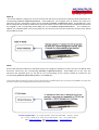
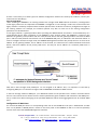
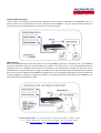
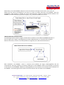
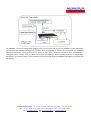
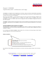
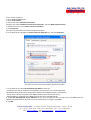
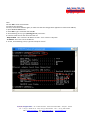
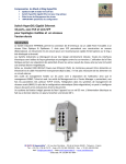
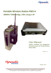
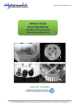
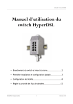
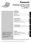
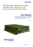
1
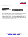
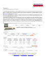
DOMINO
Broadband Bonding Aggregator
HY@DSL66501/66511
User Manual
M/M/D/S Hypercable® - 81 rue des Carrières - ZA de la Ronze 69440 - Taluyers - France
Tel: + 33 (0) 4 78 48 74 75 - Voip:+33 (0) 962 305 810 - Fax: + 33 (0) 426 031361
Mail: [email protected] - Web:www.hypercable.fr – www.worldwave.eu
– Code CEE: FR 19 384 007 894 –
Chapter 1:
Introduction
The DOMINO HY@DSL66501/66511 Broadband aggregator is a ground‐breaking device which enables aggregation
up to six regular broadband Internet connections (such as DSL, cable modem, E1) for all HTTP‐based traffic. The
HY@DSL is uniquely able to aggregate broadband Internet connections for downlink traffic at a smaller granularity
than it was possible before. This provides higher peak rates for even an individual application, such as downloading a
file. For uplink traffic, session level load balancing achieves the most efficient use of all available broadband Internet
connections.
Both the DOMINO HY@DSL66501 and DOMINO/66511 have 6 Ethernet WAN ports and 4 Ethernet LAN ports.
The WAN ports connect broadband connections from DSL modems or similar devices. Each of the LANports provides
an Internet connection for routers/switches or computers.
In addition, the DOMINO/66511 supports additional WAN connections to cellular broadband modems. One or more
cellular broadband modems can be supported through the optional PMCIA card slot or through the standard USB
ports. Each attached cellular data modem can be configured to operate either in standby mode or in aggregation
mode.
The DOMINO HY@DSL66501/66511 includes optionally enabled standard router features such as a DHCP server,
DMZ support, and port forwarding as well a powerful firewall function. The system is managed via an easy to use
web interface.
Features:
6 WAN ports compatible with any broadband modem technology, such as ADSL, ADSL2, ADSL2+, VDSL,
VDSL2, T1, Cable Modem, etc. (10/100baseT Ethernet)
4 LAN ports (10/100baseT Ethernet)
Web‐based Management Interface for easy configuration and monitoring
Can be installed in legacy networks with no re‐configuration of existing network
Configurable DHCP server for auto‐addressing (optionally enabled)
Support for DMZ and port forwarding and firewall functions (optionally enabled)
UPnP support (optionally enabled)
Parallel DNS queries on all active WAN interfaces for reduced DNS latency and increased reliability.
Automatic allocation of available WAN links without network interruption
Cellular data service failover and aggregation option (DOMINO6411)
M/M/D/S Hypercable® - 81 rue des Carrières - ZA de la Ronze 69440 - Taluyers - France
Tel: + 33 (0) 4 78 48 74 75 - Voip:+33 (0) 962 305 810 - Fax: + 33 (0) 426 031361
Mail: [email protected] - Web:www.hypercable.fr – www.worldwave.eu
– Code CEE: FR 19 384 007 894 –
Chapter 2: Domino
HY@DSL66501/66511 Hardware
The DOMINO HY@DSL66501/66511 has 6 WAN connections on the front panel, and 4 LAN ports on the back panel.
These are standard RJ45 Ethernet connections (10/100baseT) compatible with straight‐through or crossover CAT5e
cables. The WAN connections on the front label are labeled WAN1 through WAN6.
There is also a serial port connector on the front panel which is unused and reserved for future use.
Each Ethernet connector has two LED indicators associated with it. One LED is lit for a logical connection to a device
on the opposite end of the cable. The other LED is lit indicating data transfer.
An ON/OFF switch is located on the back panel. Keeping the DOMINO HY@DSL66501/66511 powered on at all times
is recommended.
An LED on the front panel indicates the unit is powered up. In addition, the DOMINO HY@DSL/66511 has a PMCIA
card slot on the back panel for a cellular data service card.
Cellular broadband data modems can also be plugged into the USB ports.
M/M/D/S Hypercable® - 81 rue des Carrières - ZA de la Ronze 69440 - Taluyers - France
Tel: + 33 (0) 4 78 48 74 75 - Voip:+33 (0) 962 305 810 - Fax: + 33 (0) 426 031361
Mail: [email protected] - Web:www.hypercable.fr – www.worldwave.eu
– Code CEE: FR 19 384 007 894 –
Chapter 3:
HY@DSLManagement Interface
The DOMINO HY@DSL66501/66511 takes approximately 60 seconds to initialize after powering up. After this is complete, to
access the HY@DSL, identify a “management computer” (e.g. a laptop PC) through which the HY@DSLManagement Interface
will be accessed. Connect an Ethernet cable from the management computer’s Ethernet port to any of the HY@DSL’s LAN ports
and visit http://192.168.254.99/ with a browser.
Note that the HY@DSLManagement Interface is accessible on any computer with a web browser on the localnetwork, so after
the local network is configured it is not necessary to plug the computer directly into the DOMINO HY@DSL66501/66511 in order
to access the HY@DSL Management Interface.
If the HY@DSL Management Interface cannot be accessed, make sure the management computer is configured so that it is
capable to accept a “dynamic IP” address from a DHCP server, in this case the DHCP server of the HY@DSL. By default, the DHCP
server of the HY@DSL is enabled, but it can be disabled through the HY@DSLManagement Interface. In order to access the
HY@DSLManagement Interface when the DHCP server is disabled and no other active DHCP is accessible, a static IP address
should be assigned to the management computer. Itis recommended to use the static IP address 192.168.254.10 for the
management computer in this case. Refer to Appendix A for typical instructions on how to manually set a static IP address on a
PC.
The DOMINO HY@DSL66501/66511 Management Interface will look similar to the following:
M/M/D/S Hypercable® - 81 rue des Carrières - ZA de la Ronze 69440 - Taluyers - France
Tel: + 33 (0) 4 78 48 74 75 - Voip:+33 (0) 962 305 810 - Fax: + 33 (0) 426 031361
Mail: [email protected] - Web:www.hypercable.fr – www.worldwave.eu
– Code CEE: FR 19 384 007 894 –
The HY@DSL Management Interface presents five tabs to access its functionality: HOME, ADVANCED,
FIREWALL, STATUS, and ADMIN.
HOME tab ‐ allows configuration of the HY@DSL LAN and each WAN port and monitoring of the status of
DOMINO HY@DSL6401/6411 including connection statistics. Also allows configuration of the DHCP server on
DOMINO HY@DSL6401/6411.
ADVANCED tab – allows configuration of features such as UPnP support, Dynamic DNS, VoIP QoS control, and
interface binding.
FIREWALL tab – allows configuration of optional firewall functions such as inbound port forwarding and
outbound traffic blocking. As a default all outgoing connections are allowed and all incoming connections are
blocked. The DMZ feature can also be configured here.
STATUS tab – displays auxiliary information about the HY@DSL for diagnosis by Mushroom Networks, Inc., a
DHCP lease table, and configuration of the remote syslog feature.
ADMIN tab – allows configuration of password access for HY@DSL Management Interface, e‐mail alarms,
external maintenance mode, software reboot, reset, and shutdown.
On‐line Help
Several blue question mark icons are displayed within the HY@DSL Management Interface. Brief explanations of
various features are displayed when these icons are clicked with the mouse.
Chapter 4:
Connect DOMINO HY@DSL66501/66511 to broadband modems
Use of the HY@DSL requires connection of one or more modems (e.g. DSL, cable, or cellular broadband) to the
DOMINO HY@DSL66501/66511 . Configure the modems for operation according to the ISP's instructions and then
configure the WAN ports of the DOMINO HY@DSL66501/66511 . As described later in this chapter, in many cases the
modems will be set for DHCP which is the default in DOMINO HY@DSL66501/66511 and no additional configuration
is required. Some cable modems may require a power‐cycle (turn off and on) to associate with a new MAC address
after connecting to the HY@DSL 1. In order to connect each wireline modem, use an Ethernet cable to connect the
“LAN” or “Ethernet” port of the modem and connect the other end of the cable to any WAN port 1, 2, 3, 4, 5 or 6 of
the DOMINO HY@DSL66501/66511 front panel. One of the LEDs on the connector used on the DOMINO
HY@DSL66501/66511 will light up after both the modem and the DOMINO HY@DSL66501/66511 are powered on
and the modem is properly connected to the HY@DSL .
If the modems do not use DHCP, the WAN connection details will need to be configured for each non DHCP modem
in the HY@DSL Management Interface, as detailed below.
IP Addressing on DOMINO Wired WAN Ports
Each active wired WAN port on the HY@DSL66501/66511 connected to a modem (e.g. DSL, cable)
needs to be configured with an IP address. For each active WAN port on the DOMINO HY@DSL66501/66511? one of
the following configuration methods needs to be selected:
DHCP ‐ This is the default configuration mode for each wired WAN port on the TRUFFLE HY@DSL66501/66511.
Typically a DSL or cable modem will have a DHCP server which is capable of assigning anIP address, called a dynamic
IP address. In this case the DSL or cable modem will automatically configure the attached wired WAN port on the
HY@DSL66501/66511 and no user configuration is necessary.
M/M/D/S Hypercable® - 81 rue des Carrières - ZA de la Ronze 69440 - Taluyers - France
Tel: + 33 (0) 4 78 48 74 75 - Voip:+33 (0) 962 305 810 - Fax: + 33 (0) 426 031361
Mail: [email protected] - Web:www.hypercable.fr – www.worldwave.eu
– Code CEE: FR 19 384 007 894 –
Static IP
‐ If a static IP address is assigned to a service account from the ISP, then the Static IP mode should be selected for the
corresponding DOMINO HY@DSL66501/66511 wired WAN port. The assigned static IP address will need to be
entered in the user configuration tab for the corresponding DOMINO HY@DSL66501/66511 wired WAN port. If the
ISP has assigned several static IP addresses for the same service account, one of these static IP addresses will need to
be assigned to the corresponding wired WAN port on the DOMINO HY@DSL66501/66511 . The “Gateway IP”
address, the “Network Mask” and “primary DNS” for the service account will also need to be entered, which should
be provided by the ISP.
PPPoE –
Some of the older DSL modems use the PPPoE protocol to configure IP addresses. If that is the case, the PPPoE mode
should be selected for the corresponding DOMINO HY@DSL66501/66511 wired WAN port. In this case, the
username and password given by the ISP for the corresponding service account should be entered for the
corresponding DOMINO HY@DSL66501/66511 wired WAN port.
1 Some older models of modems may require a reset to associate with a new MAC address when connecting to the DOMINO. This may further
require the modems to be reconfigured with the parameters from the ISP.
M/M/D/S Hypercable® - 81 rue des Carrières - ZA de la Ronze 69440 - Taluyers - France
Tel: + 33 (0) 4 78 48 74 75 - Voip:+33 (0) 962 305 810 - Fax: + 33 (0) 426 031361
Mail: [email protected] - Web:www.hypercable.fr – www.worldwave.eu
– Code CEE: FR 19 384 007 894 –
If there is uncertainty as to what type of IP address configuration schemes are used by the modems, contact your
Internet Service Provider(s).
Pass Through Mode –
When installing the DOMINO in an existing network with a single wired WAN backhaul connection, reconfiguration
of the legacy network is not required if the DOMINO is configured in “Pass Through” mode. This can be useful if the
legacy network is relatively complex and the network operator does not desire to make any configuration changes to
the existing network. For example, the network operator may wish to retain all of the existing configuration
parameters of a firewall device.
In the legacy network, a gateway/modem device providing the WAN backhaul connection is connected directly to a
router/firewall device. After installation of the DOMINO in Pass Through mode, the DOMINO is inserted in‐line
between the gateway router/modem and the router/firewall device with the gateway/modem connected to WAN
port 1 and the router/firewall connected to one of the DOMINO LAN ports, as indicated in the illustration below. In
order to configure the Pass Through mode, the DOMINO Management Interface will prompt the user to enter the IP
address of the gateway/modem, the IP address of the firewall, the netmask of the network behind the firewall
device, and the IP address of the primary DNS server. An entry for the IP address of a secondary DNS server is
optional.
Note that in Pass Through mode, WAN port 1 is not assigned an IP address. Also, it is important to note that by
configuring WAN port 1 in the Pass Through mode the DOMINO will disable its DHCP server2.
In the Pass Through mode on WAN port 1, an additional subnet can be specified. This is useful in situations where
there is a local subnet that is distinct from the subnet specified the given IP address and netmask for the WAN port 1
set‐up. Traffic from devices belonging to the specified additional subnet will be aggregated across all available WAN
ports.
Configuration of WAN Ports
For each wired WAN port there is a corresponding status row on the HOME tab. Each port is labeled with an index
from 1 to 6 (WAN1 to WAN6) which is visible on the front panel of the DOMINO as well as in the first (leftmost)
column of the tab of the DOMINO Management Interface.
M/M/D/S Hypercable® - 81 rue des Carrières - ZA de la Ronze 69440 - Taluyers - France
Tel: + 33 (0) 4 78 48 74 75 - Voip:+33 (0) 962 305 810 - Fax: + 33 (0) 426 031361
Mail: [email protected] - Web:www.hypercable.fr – www.worldwave.eu
– Code CEE: FR 19 384 007 894 –
To configure a wired WAN port, click on the corresponding port index in the first column of the tab. If the wired WAN
port is not being used, select the “DISABLE” radio button and click “SAVE”. Otherwise, select the “ENABLE” radio
button and select the configuration mode for the WAN port, either DHCP, Static, or,PPPoE, or Pass Through, as
appropriate, as discussed in the previous section.
Standby Mode
Each enabled WAN port can be put in “Standby” mode if desired. In the Standby mode, a WAN port will not be
normally used unless no other WAN connectivity is available. This mode would be used if it is desired to use the WAN
resource only as a backup in case of failure of the primary WAN connection(s). In order to put a WAN port in Standby
mode, select the displayed check box.
Inbound Subnet Aliasing
For each WAN port configured in the “Static IP” mode, there is an option to activate “Inbound Subnet Aliasing”. If
this option is enabled, the DOMINO device will act as a proxy in the ARP protocol for all IP addresses in the IP address
range specified by the given IP address and subnet mask. This may be necessary in order for traffic inbound from the
Internet to reach all of the devices in the specified subnet.
After configuring each wired WAN port, click “OK” to save the corresponding WAN port settings. For Static IP, there
will be a prompt to enter the “static IP address”, “Gateway address”, the “network mask”
and the “primary DNS” provided by the ISP. Check the box for Inbound Subnet Aliasing if this is desired. For PPPoE,
there will be a prompt for the username and password provided for the service account by the ISP.
2 As a result, when the DOMINO is configured in Pass Through mode, it may be necessary to manually assign a static IP address to the PC which is
used to access the DOMINO Management Interface, if there is no active DHCP server to assign it a dynamic IP address.
M/M/D/S Hypercable® - 81 rue des Carrières - ZA de la Ronze 69440 - Taluyers - France
Tel: + 33 (0) 4 78 48 74 75 - Voip:+33 (0) 962 305 810 - Fax: + 33 (0) 426 031361
Mail: [email protected] - Web:www.hypercable.fr – www.worldwave.eu
– Code CEE: FR 19 384 007 894 –
For Pass Through mode, which is available on WAN port 1 only, there will be a prompt to enter the IP address
(“Gateway Address”) of the gateway/modem device to be connected to WAN port 1, the IP address (“Firewall IP”) of
the router/firewall device to be connected to the DOMINO LAN port, the network mask (“Mask”) of the network
behind the firewall device, and the IP address of the primary DNS server. An entry for the IP address of a secondary
DNS server is optional. If an additional subnet is present, enter the subnet address in CIDR notation, e.g.
172.16.1.0/24. If an additional subnet is not present the corresponding field should be left blank.
By configuring WAN port 1 in the Pass Through mode, the DOMINO will disable its DHCP server. As a result,
when the DOMINO is configured in Pass Through mode it may be necessary to manually assign a static IP address to
the management computer in order to access the DOMINO Management Interface if there is no active DHCP server
to assign the management computer a dynamic IP address.
Since there is probably more than one service account being used with the DOMINO, check carefully to make sure
the information entered corresponds to the correct modem and port index as determined by how the modems are
connected to the DOMINO HY@DSL66501/66511 with the Ethernet cables.
Once a WAN port is configured, the “MAC Address” and “IP Address” columns for the corresponding row
will be filled in automatically. The “External IP Address” is the IP address that can be used to reach the corresponding
WAN port from the Internet. This address will usually differ from the IP address of the WAN port when a dynamic IP
address is assigned via DHCP. The “Status” column corresponding to the WAN port will be updated, as appropriate.
For each active WAN port, the menu will show the rate information on each interface for monitoring the status of
each Internet connection in real time.
Using a Cellular Mobile Data Card
The TRUFFLE DOMINO 6411 has a PMCIA card slot at the back panel that can support an additional WAN
connection for your DOMINO from a cellular data modem. The DOMINO 6411 can also support up to two cellular
data modems through the USB ports.
The following cellular data modems are currently supported:
AirCard 881 PCMCIA
AirCard 595 PCMCIA
AirCard 595U – USB
Compass 597 – USB
Merlin EX720 – PCMCIA/USB –
Ovation U720 ‐ USB
Novatel U727 ‐ USB
Kyocera KPC680 ‐ USB
ZTE MG880 – USB
UM150/UM175 – USB
Huawei E172 – USB
M/M/D/S Hypercable® - 81 rue des Carrières - ZA de la Ronze 69440 - Taluyers - France
Tel: + 33 (0) 4 78 48 74 75 - Voip:+33 (0) 962 305 810 - Fax: + 33 (0) 426 031361
Mail: [email protected] - Web:www.hypercable.fr – www.worldwave.eu
– Code CEE: FR 19 384 007 894 –
In order to use your data card, first configure it with your personal computer using the instructions from
your mobile wireless service provider. Once the card is configured, you can use it with your DOMINO 6411.
To do this, plug your wireless data card into the back of the DOMINO HY@DSL66511 after it has booted up. If you are
using a PCMCIA cellular data modem, note that the card plugs into the back of the DOMINO in an inverted
orientation (i.e. upside down).
After a few seconds, the DOMINO management interface will include status for Wireless WAN (WWAN) interface(s)
in the table displayed at the bottom of the home tab.
A wireless WAN interface can be either in standby mode, or in aggregation mode. When the wirelessWAN interface
is in standby mode, it will only be used when all other WAN interfaces are in the in‐active state. This is useful if the
wireless WAN interface is for a service provider that charges a fee that depends on the amount of usage of the
service.
When at least one of the other interfaces enters the active state, the wireless WAN interface will not be used, while
it is in standby mode. On the other hand, when the wireless WAN interface is in the aggregation mode, the TRUFFLE
will use the wireless WAN interface as much as possible in order to improve performance.
In order to configure the wireless WAN interface is in standby mode or not, display the home page on the DOMINO
management interface. Click the mouse on the interface index on the leftmost side of the WWAN connection table.
A menu is displayed asking the user to select Standby mode or not for the corresponding interface.
Chapter 5:
Connect PCs and network to DOMINO HY@DSL66501/66511
After setting up the modem(s) that are connected to the TRUFFLE DOMINO 6401/6411, any of the LAN ports on the
TRUFFLE DOMINO 6401/6411 will access bonded Internet links. There are several ways the DOMINO LAN ports can
be used:
As a regular Ethernet connection:
Connect an Ethernet cable to any of the LAN ports of the DOMINO andattach the other end of the Ethernet cable to
a PC/Laptop which is to be provided bonded Internet access. Other PC/Laptops can plug into the other LAN ports of
the DOMINO .
M/M/D/S Hypercable® - 81 rue des Carrières - ZA de la Ronze 69440 - Taluyers - France
Tel: + 33 (0) 4 78 48 74 75 - Voip:+33 (0) 962 305 810 - Fax: + 33 (0) 426 031361
Mail: [email protected] - Web:www.hypercable.fr – www.worldwave.eu
– Code CEE: FR 19 384 007 894 –
Using an Ethernet switch:
If the number of PC/Laptops to be supported is greater than the number of LAN ports on the DOMINO (four), an
Ethernet switch can be connected to one of the LAN ports of the DOMINO . Any port of the Ethernet switch may
now also be used to provide bonded Internet access to a local PC/Laptop.
With a Router:
Connect the WAN/Internet port of the router to one of the DOMINO LAN ports. The DHCP server in the DOMINO
should be enabled to assign the router/firewall an IP address. The DHCP server in the router/firewall should be
enabled for the host computer devices which are attached to the router/firewall through the LAN ports of the
router/firewall. It may be necessary to configure the DHCP server of the router/firewall to set the DNS server address
for its clients to the IP address of the DOMINO (by default this is set to 192.168.254.99) rather than the IP address of
an external DNS server. With this configuration, UPnP is not supported and should be disabled on the DOMINO (see
advanced features) and within the router.
M/M/D/S Hypercable® - 81 rue des Carrières - ZA de la Ronze 69440 - Taluyers - France
Tel: + 33 (0) 4 78 48 74 75 - Voip:+33 (0) 962 305 810 - Fax: + 33 (0) 426 031361
Mail: [email protected] - Web:www.hypercable.fr – www.worldwave.eu
– Code CEE: FR 19 384 007 894 –
Alternatively, one of the DOMINO LAN ports can be connected to a LAN port on the router. In this case, the
DHCP server will need to be disabled on the router so it does not conflict with that of the DOMINO . With this
configuration, UPnP support is available. For correct UPnP operation, support for UPnP should be enabled in the
DOMINO (see advanced features) and UPnP support, if any, should be disabled in the router.
CONFIGURING PASS THROUGH MODE
The following illustration depicts a legacy network before installation of the TRUFFLE DOMINO 6401/6411 in
Pass Through mode. A legacy modem/gateway provides a WAN backhaul to a router/firewall through an
Ethernet connection, as shown. The router/firewall is the gateway for a LAN and attached devices.
After installation, the DOMINO device is inserted in‐line between the legacy modem/gateway and the
router/firewall. The legacy modem/is connected to WAN port 1 of the DOMINO and the router/firewall is connected
to the LAN port of the DOMINO . Additional modem/gateways for the network are connected to other WAN ports of
the DOMINO . The following illustration depicts the network above after installation of the DOMINO .
M/M/D/S Hypercable® - 81 rue des Carrières - ZA de la Ronze 69440 - Taluyers - France
Tel: + 33 (0) 4 78 48 74 75 - Voip:+33 (0) 962 305 810 - Fax: + 33 (0) 426 031361
Mail: [email protected] - Web:www.hypercable.fr – www.worldwave.eu
– Code CEE: FR 19 384 007 894 –
The DOMINO can first be configured by plugging a PC into one of the LAN ports of the DOMINO as illustrated above
and accessing the DOMINO Management Interface. After the DOMINO is appropriately configured, the DOMINO
Management Interface can be accessed by any PC on the Local LAN. It should be noted that when the DOMINO is
configured in Pass Through mode, the DHCP server within the DOMINO will be disabled. Therefore, it will generally
be necessary to manually assign a static IP address to the PC through which the DOMINO Management Interface will
be accessed.
M/M/D/S Hypercable® - 81 rue des Carrières - ZA de la Ronze 69440 - Taluyers - France
Tel: + 33 (0) 4 78 48 74 75 - Voip:+33 (0) 962 305 810 - Fax: + 33 (0) 426 031361
Mail: [email protected] - Web:www.hypercable.fr – www.worldwave.eu
– Code CEE: FR 19 384 007 894 –
Chapter 6: Advanced Features
In this chapter, the advanced features of the DOMINO are described.
IP Address for DOMINO LAN
By default, the LAN interface of the DOMINO is assigned the IP address 192.168.254.99. This is the IP address
through which the DOMINO Management Interface is accessed. It is possible to change the IP address of
theDOMINO LAN interface.
This should be done with extreme care, as changing this will affect the manner in which the DOMINO Management
Interface is accessed. In particular, it is important to remember the IP address assigned to the DOMINO LAN. It will
not be possible to access the DOMINO Management Interface without this information.
In order to set the DOMINO LAN IP address, click on the HOME tab of the DOMINO Management Interface. In
the LAN configuration table, in the “Interface” column, click on the link “LAN”. A prompt appears requesting an IP
address be entered. If the value is changed for this IP address, it is imperative that the new value be remembered.
The network mask for the DOMINO LAN can also be set here (“Mask”). By default, the network mask is set to
255.255.255.0
Note:
The IP address assigned to the LAN interface of the DOMINO must be a private IP address, according to the Internet
Assigned Numbers Authority (IANA) in RFC 1918, specifically it must be in the range of 10.0.0.0 ‐10.255.255.255
(10/8 prefix), 172.16.0.0 ‐172.31.255.255 (172.16/12 prefix), or 192.168.0.0 ‐ 192.168.255.255 (192.168/16 prefix).
Devices attached to the DOMINO LAN may be externally accessed via the Internet using an Inbound firewall rule,
which may map a public IP address with a particular port to a private IP address within the DOMINO LAN.
Alternatively, if the Pass Through feature is used, an additional IP subnet may be configured which will be externally
addressable via the public Internet. This is discussed in Chapter 4.
DHCP Server
The DHCP server on the DOMINO can be enabled or disabled via the radio buttons on the HOME tab in the LAN
configuration table. The “starting IP address” for the DHCP server can also be configured here. When the DHCP
server inside the DOMINO is enabled, it will start assigning dynamic IP addresses starting from the configured
address. This may be useful in some cases to avoid conflicts with manually assigned static IP addresses. The default
starting IP address is 192.168.254.100
The DHCP server is enabled by default. It is automatically disabled when the Pass Through mode is enabled on WAN
port 1.
Support for UPnP
By default, the DOMINO is configured to support UPnP which enables auto‐configuration of IP addressing
features for certain applications. In order to enable or disable support for UPnP, select the ADVANCED tab within the
DOMINO Management Interface and click on the link labeled “Enabled” or “Disabled” in the entry for UPnP in the
configuration table. You can then select “Enabled” or “Disabled” by selecting the appropriate radio button and
clicking “Apply.” Normally, support for UPnP should be disabled when running the DOMINO in Pass Through mode
since this functionality would already be provided by a device in the legacy network.
M/M/D/S Hypercable® - 81 rue des Carrières - ZA de la Ronze 69440 - Taluyers - France
Tel: + 33 (0) 4 78 48 74 75 - Voip:+33 (0) 962 305 810 - Fax: + 33 (0) 426 031361
Mail: [email protected] - Web:www.hypercable.fr – www.worldwave.eu
– Code CEE: FR 19 384 007 894 –
Inbound Port Forwarding
Inbound port forwarding allows external computers on the Internet to access devices in the local network through
the same IP address. Normally this feature is used with static IP address assignment, but it can be used with any of
the IP address configuration modes for the DOMINO WAN ports. Inbound
port forwarding is also not recommended for the Pass Through mode of operation since this function, if
needed, would already be handled by the legacy network.
By default, all inbound Internet traffic is blocked. Selected inbound Internet traffic can be allowed by configuration of
one or more forwarding rules. To configure a rule for forwarding inbound Internet traffic, select the “FIREWALL” tab ,
and click on the “Add Firewall Rule” button. Select “Permit Inbound” as a “Direction.” Specifying a WAN port number
will cause all traffic destined to the specified port to be forwarded to the specified “Local IP” address. It will be
delivered to the same destination port unless a LAN port is specified, in which case it will be delivered to the
specified LAN port. A WAN interface can also specified for the rule. Specifying an interface other than “ALL” will
cause only that traffic inbound on the specified interface to be forwarded to the specified “Local IP” address. A
“Global IP” address may also be optionally specified, which signifies that only that traffic which is destined to the
specified Global IP address should be forwarded to the specified Local IP address. Finally, TCP traffic or UDP traffic
can be forwarded by selecting the corresponding “protocol” choice in the menu.
After specifying all desired conditions in a forwarding rule for inbound traffic, click on “Add” to load the forwarding
rule into the DOMINO . Multiple forwarding rules can be added in order to provide more flexible forwarding of
traffic. If a forwarding rule that was added previously needs to be deleted, click the “DELETE” button next to the
listed forwarding rule. If a forwarding rule needs to be edited, the rule can first be deleted and the modified rule can
then be entered as before.
Outbound Port Blocking
Outbound port blocking allows a network operator to block all outgoing traffic from a specified source port, protocol,
and optionally a specified source IP address.
By default, all outbound Internet traffic is allowed. To configure a rule for blocking outbound Internet traffic click the
“FIREWALL” tab to display the menu and click on the “Add Firewall Rule”. Select the “Deny Outbound” as a
“Direction” and specify the source port index for which outgoing traffic should be blocked. Optionally, a source IP
address can also be specified to block only traffic from the specified source IP address with the specified source port
index. The protocol traffic that should be blocked, TCP or UDP, must also be selected.
Multiple outbound blocking rules can be added in order to provide more flexible blocking of traffic. If a traffic
blocking rule that was added previously needs to be deleted, click the “DELETE” button next to the listed blocking
rule. If a blocking rule needs to be edited, the rule can first be deleted and the modified rule can then be entered as
before.
Normally outbound blocking rules should not be specified when the DOMINO is configured in Pass Through mode
since such blocking would already be done by the legacy network.
M/M/D/S Hypercable® - 81 rue des Carrières - ZA de la Ronze 69440 - Taluyers - France
Tel: + 33 (0) 4 78 48 74 75 - Voip:+33 (0) 962 305 810 - Fax: + 33 (0) 426 031361
Mail: [email protected] - Web:www.hypercable.fr – www.worldwave.eu
– Code CEE: FR 19 384 007 894 –
DMZ Support
Support for a DMZ (demilitarized zone) can also be enabled through the FIREWALL tab with the DOMINO
Management Interface. The DMZ feature of the TRUFFLE DOMINO 6401/6411 allows the user to specify the IP
address of a local computer that has been designated as the DMZ. The specified IP address is called the DMZ IP
address. When the DOMINO receives a packet from the Internet over any of the WAN ports then the DOMINO will
forward a packet to the specified DMZ address if none of the port forwarding rules apply to the given packet. If no
port forwarding rules are specified and a DMZ IP address is specified, then all packets received on a WAN port will be
forwarded to the local computer with the specified DMZ IP address. It should be noted that if one or more port
forwarding rules are specified that they will take precedence over the forwarding of traffic to a DMZ, if the DMZ
feature is enabled. Moreover, it should be noted that any port forwarding that occurs as a result of the UPnP feature
being enabled will take precedence over any port forwarding rules. Setting up a DMZ is useful if there are several
computers in the local network, but only one of them (that has been designated as the DMZ) is desired to be directly
accessible via the Internet. Normally, support for DMZ should be disabled when running the DOMINO in Pass
Through mode since a DMZ would already be implemented in the legacy network.
The DMZ feature can be configured by clicking on the status entry “Enabled” or “Disabled” for DMZ in the
configuration table and selecting the appropriate radio button. If the “Enable” button is selected, then the IP address
for the DMZ must be specified. By clicking on “Apply” the DMZ feature is configured accordingly.
Dynamic DNS
The DOMINO supports inbound load balancing and inbound link fail‐over via Dynamic DNS (DDNS). This feature
allows management of inbound traffic (traffic which is originally initiated from within the Internet). This feature is
configured via the ADVANCED tab. It is disabled by default and two modes are supported currently through the
Dynamic DNS service at afraid.org and dyndns.org, respectively. To properly configure this feature, a service account
should first be set up with afraid.org or dyndns.org. Details of the service are available from these service providers.
Once the service account has been set up the corresponding mode can be selected by clicking on the status entry
(“Disabled” or “Enabled”) for “Dynamic DNS” in the configuration table. The various options will be displayed, and
the DOMINO Management Interface will then prompt for a Username, Password, and Hostname, which should be
provided by the Dynamic DNS provider. By clicking on “Apply”the Dynamic DNS feature is configured accordingly.
For afraid.org's round robin DDNS to work correctly requires unlinking of entries for the same domain (one entry for
each DOMINO WAN connection is required). See the afraid.org FAQ for more information:
http://freedns.afraid.org/
Note: DDNS is service that is hosted by companies with no connection to MMDS Hypercable . MMDS Hypercable
makes no warranty as to the reliability of these services. For mission critical applications, it is strongly advised that
the reliability of the service used be considered before deployment.
M/M/D/S Hypercable® - 81 rue des Carrières - ZA de la Ronze 69440 - Taluyers - France
Tel: + 33 (0) 4 78 48 74 75 - Voip:+33 (0) 962 305 810 - Fax: + 33 (0) 426 031361
Mail: [email protected] - Web:www.hypercable.fr – www.worldwave.eu
– Code CEE: FR 19 384 007 894 –
Interface Binding Support
The DOMINO also supports binding of specific outbound traffic to a specified WAN interface. This is sometimes
useful for some applications or users that require certain traffic to be routed over the same WAN interface. In order
to configure the interface binding feature, click on the “ADVANCED” tab. To configure a interface binding rule, click
on the “Add Interface Binding Rule” button. This will generate a pop up window where the information specifying an
interface binding rule can be specified. The rule action is specified by an “Interface” which can be either WIRED WAN
1, WIRED WAN 2, WIRED WAN 3, WIRED WAN 4, or possibly “Cellular WAN 1” if a cellular broadband data modem is
plugged into the DOMINO . The specified traffic will be preferentially routed over the WAN interface with the index
that is selected for the rule.
The traffic specification for the rule consists of a protocol designation, a port number, and an IP address. Only
packets which match the corresponding protocol designation, port number, and IP address will be affected by the
rule (i.e. the “and” of these three conditions). A match for the port number occurs when either the source port field
or the destination port field matches with the port number(s) specified. A port number specification can be a single
integer, but it can also be a range. For example, 56‐59 would be the range that includes 56,57,58, and 59. Values and
ranges can also be separated by commas. For example, “56,59” corresponds to the set containing the values 56 and
59. If the port number field is left blank, there will be no match condition applied to the source port or destination
port fields.
A match for the IP address occurs when either the source IP address of the packet or the destination IP address of
the packet matches with the given IP address. If the IP address field is left blank then there will be no match
condition applied to the IP address field.
The protocol designation can be ANY, TCP, UDP, IPSEC, or PPTP. The ANY choice means any protocol. All of the match
conditions, if any, for the port number, the IP address, and the protocol designation must be met in order to trigger
the port forwarding rule. When the port forwarding rule is triggered, the traffic is routed in the manner specified, i.e.
WIRED WAN 1, WIRED WAN 2, WIRED WAN 3, WIRED WAN 4, or possibly “Cellular WAN 1” if a cellular broadband
data modem is plugged into the DOMINO . An optional “Note” field is provided for convenience and typically is used
to document what the interface binding rule is used for (e.g. for a particular application or user). Once all the
information for an interface binding rule has been entered, click “ADD” to enable the rule.
Multiple interface binding rules can be added in order to provide more flexible binding of traffic. If an interface
binding rule that was added previously needs to be deleted, click the “DELETE” button next to the listed binding rule.
If an interface binding rule needs to be edited, the rule can first be deleted and the modified rule can then be
entered as before.
There are two port numbers that are special and not allowed for interface binding. Specifically, traffic on port 80
(HTTP) and port 443 (SSL) cannot be configured for interface‐binding.
The conditions describing different interface binding rules must be non‐overlapping. Thus if a packet meets the
conditions for one rule it must not meet the conditions for any other rule. If the DOMINO Management interface
detects a conflict for a new rule, it will not allow the new rule to be added.
M/M/D/S Hypercable® - 81 rue des Carrières - ZA de la Ronze 69440 - Taluyers - France
Tel: + 33 (0) 4 78 48 74 75 - Voip:+33 (0) 962 305 810 - Fax: + 33 (0) 426 031361
Mail: [email protected] - Web:www.hypercable.fr – www.worldwave.eu
– Code CEE: FR 19 384 007 894 –
List of DHCP Leases
A list of all dynamic IP addresses leased out by the DOMINO DHCP server can be viewed by clicking on the “STATUS”
tab. The MAC address, IP address, and possibly the machine name are listed for each IP address lease.
Remote Syslog
A log of DOMINO system events appears in the “STATUS” tab. The IP address of a Remote Syslog Server can be
specified which is to be the recipient of log messages generated by the DOMINO . After the IP address of the Remote
Syslog Server has been specified, click “APPLY” to configure this feature.
Web Interface Password
The DOMINO Management Interface can be configured so that it can be accessed only with entry of a username and
password. With the default factory settings, no entry of a password is required. The DOMINO Management Interface
password can be configured in the “ADMIN” tab so that a entry of a password is required to access it. To configure
the feature, click on the status for “Web Interface Password” – which will be either “Disabled” or “Enabled.”
The default username is “admin” (without the quotes). The password can be set by entering it in the “Web Interface
Password” field. It is required to type in the password twice to ensure it is accurately recorded. The password will be
set after “APPLY” is clicked. Configuration of this feature will cause the DOMINO to restart. The password should be
changed with extreme care –if it is forgotten or mistyped it will not be possible to access the DOMINO Management
Interface.
Remote Web Interface Port
The DOMINO Management Interface can be configured so that it can be accessed externally from the Internet via
the DOMINO WAN ports. To enable this feature, go to the “ADMIN” tab and click on the status indicator of the
“Remote Web Interface Port” entry in the displayed status table. The pop‐up window allows configuration of the
feature. If the feature is enabled, a port number must be specified.
If the feature is enabled, the DOMINO Management Interface can be remotely accessed from the Internet through
any of the public IP addresses for the DOMINO . These public IP addresses can be obtained from the “External IP”
column in the WAN status table on the HOME tab of the DOMINO Management Interface. The URL through which
the DOMINO Management Interface can be accessed is given by the external IP address appended with the assigned
port number. For example, if one of the external IP addresses for the DOMINO is 76.211.117.87 and the Remote
Web Interface is enabled through port 8080, then the DOMINO Management Interface can be accessed
through the URL http://76.211.117.87:8080
If the Pass Through mode is enabled on WAN interface 1, and this feature is enabled, the DOMINO Management
Interface can be accessed externally from the Internet through the IP address of the Router/Firewall connected to
the LAN port of the DOMINO . For example, if the IP address of this router is 76.37.181.2 and the Remote Web
Interface is enabled through port 8080, then the DOMINO Management Interface can be externally accessed
through the URL http://76.37.181.2:8080. Note however in this example that from a host on the LAN of the DOMINO
, packets addressed to 76.37.181.2 will be forwarded to the Router/Firewall and not the DOMINO . To access the
DOMINO Management Interface from the DOMINO LAN, the DOMINO LAN address should be used, e.g the default
DOMINO LAN address 192.168.254.99. If the Remote Web Interface is enabled, then it is highly recommended that a
web interface password be configured to prevent unauthorized access to the DOMINO from the public Internet.
Maintenance Mode
The TRUFFLE DOMINO 6401/6411 has a maintenance mode for remote troubleshooting by personnel at Mushroom
Networks. This allows external access to the DOMINO by Mushroom Networks personnel over the Internet.
Normally this mode should be disabled, and it is disabled in the default factory settings. This mode should be enabled
M/M/D/S Hypercable® - 81 rue des Carrières - ZA de la Ronze 69440 - Taluyers - France
Tel: + 33 (0) 4 78 48 74 75 - Voip:+33 (0) 962 305 810 - Fax: + 33 (0) 426 031361
Mail: [email protected] - Web:www.hypercable.fr – www.worldwave.eu
– Code CEE: FR 19 384 007 894 –
only after consultation with Customer Support. The mode can be configured through the “ADMIN” tab. To configure
the feature, click on the status for “Maintenance Mode” – which will be either “Disabled” or “Enabled.” This will
generate a pop up window to prompt the user to configure the feature. Click “Apply” to make the change after you
have made your selection.
E‐mail Alarms
The DOMINO also supports sending of e‐mail alarms to a specified address when a “serious” event occurs. A serious
event is defined as when a WAN interface goes down or comes back up without manually enabling or disabling the
WAN interface.
In order to configure e‐mail alarms, go to the “ADMIN” tab. Click on the status for “Mail Notification,” which will be
either “Disabled” or “Enabled”. The e‐mail address and the IP address of the SMTP server which is to receive the
alarms can be entered in the pop up window that results. Typically this will be an SMTP server on the DOMINO LAN.
In order to test the configuration, a WAN interface can be purposefully brought down and up again by disconnecting
the cable from an active WAN interface which will trigger an e‐mail alarm to be sent to the designated address and
server.
SNMP Support
The DOMINO has an optional SNMP (Simple Network Management Protocol) interface which can be accessed by any
SNMP browser or SNMP client application. The DOMINO supports the mib‐2 management information base(MIB).
To access the interface the IP address of the DOMINO LAN should be used. By default this is 192.168.254.99, but will
be different if this was changed in the DOMINO 6401/6411 Management Interface. Note that any host on the
DOMINO LAN can access the SNMP interface. For external network access to the SNMP interface the DOMINO
firewall will need to be configured to allow SNMP traffic from the outside that uses port 161. To do this, go to the
“FIREWALL” tab in the TRUFFLE DOMINO 6401/6411 Management Interface and add a rule that permits inbound
traffic on port 161 for the UDP protocol. In rare cases it may be necessary to also add a rule that permits inbound
traffic on port 161 for the TCP protocol.
Voice over IP Support
The DOMINO has an optional feature that was designed for users who have configured Voice over IP (VOIP) or other
real‐time traffic to be routed over a single interface. Such a configuration of the routing of traffic can be achieved
with the interface binding feature as explained previously. File download activity over an interface can adversely
affect VOIP and other real‐time applications that use the same interface. The VOIP feature allows the DOMINO to be
configured to limit the total rate of in‐bound TCP traffic over each interface. In doing so, VOIP and other real‐time
applications can be protected from being overwhelmed by TCP traffic on that interface. The VOIP support feature
can be configured through the “ADVANCED” tab on the DOMINO management interface. In order to enable the
feature, the index of the interface through which the inbound TCP traffic will be limited needs to be specified. This
can be achieved by selecting the appropriate index in the drop down menu. A positive integer is also specified, which
represents the maximum in‐bound data rate on the specified interface, in units of kilobits per second. Finally, an
integer “quality” index ranging from 1 to 9 is also specified. Once these are specified, the feature is activated by
pressing the “ADD” button, and the corresponding data is displayed in a table. The feature can be re‐configured
or changed by pressing the “DELETE” button adjacent
to the table, and re‐entering the data. Different configurations may be applied on each WAN interface. The in‐bound
rate of TCP is limited to ((10‐Q)/10) x Max_Rate, where Q is the quality index and Max_rate is the specified maximum
in‐bound rate in kilobits per second. As an example, suppose the DOMINO is configured such that VOIP traffic is
routed over interface WAN2. Suppose that interface WAN2 is connected to a DSL line with a maximum downlink
speed of 6 Mbits/sec. In this case, the VOIP feature can be enabled by specifying interface “Wired WAN 2”, and
entering 6000 for the Max bandwidth parameter. If the quality index is set to 2, then the rate of in‐bound TCP traffic
on interface WAN2 will be limited to 4.8Mbits/sec. If the quality index is set to 8, the rate of in‐bound TCP traffic on
interface 2 will be limited to 1.2Mbits/second. In the latter case, more bandwidth is effectively reserved for VOIP or
other real‐time traffic.
M/M/D/S Hypercable® - 81 rue des Carrières - ZA de la Ronze 69440 - Taluyers - France
Tel: + 33 (0) 4 78 48 74 75 - Voip:+33 (0) 962 305 810 - Fax: + 33 (0) 426 031361
Mail: [email protected] - Web:www.hypercable.fr – www.worldwave.eu
– Code CEE: FR 19 384 007 894 –
Virtual Leased Line (optional feature)
The DOMINO can be configured to mate with another DOMINO device to create a data communication tunnel
between the pair of DOMINO units. By virtue of combining the capacity of multiple resources, the capacity of the
tunnel created can be close to the sum of the capacity of the individual resources.
Moreover, the reliability of the communication tunnel is increased since the communication tunnel will remain
operational as long as there is at least one active communication path between the DOMINO devices. It is also
possible for each DOMINO to mate with multiple DOMINO devices. A bi‐directional tunnel can be set up between
each pair of DOMINO devices. For each bi‐directional tunnel, one DOMINO device is designated as a “server” and
the other is designated as a “client”. For example, one DOMINO device might act as a server for several other
DOMINO devices, each of which acts as a client.
A tunnel can be configured in two possible modes. For each end of the tunnel, there is an associated LAN address. In
the default mode, traffic that appears at one DOMINO that matches the associated LAN address of the remote
DOMINO will be forwarded to the remote DOMINO through the tunnel. In the other mode, called the called the
proxy mode, all traffic that appears at the DOMINO on the client side that does not match the local LAN address is
sent to the remote DOMINO device over the tunnel.
Also, in the proxy mode, traffic appearing at the DOMINO on the server side that matches the LAN address of the
DOMINO on the client side will be forwarded to the DOMINO device on the client side over the tunnel. LAN
addresses are specified by an IP address and associated network mask. The VLL feature is configured through the
HOME tab of the DOMINO management interface. On the HOME page there is a table labeled “Remote LAN.” It will
look similar to the following.
In order to create a tunnel, two DOMINO devices are required. A tunnel is configured by creating an instance of a
server connection at one DOMINO and creating a matching instance of a client connection at the other DOMINO .
For security purposes, each bi‐directional tunnel has an associated “Connection Name” and password, which must
be specified identically at each end of the tunnel when the tunnel is configured. In order to create an instance of a
server connection or a client connection at a DOMINO device, click on the HOME tab of the DOMINO management
interface for that DOMINO device.
Click on the “Add Remote LAN” button at the top of the Remote LAN table. A pop‐up window will appear, and the
Connection Mode can be selected as “Client” or “Server” in the menu at the top.
For a device to be configured in Server mode, select “Server” for the Connection mode in the drop down
menu. Enter a text string for the “Connection Name” field, and an associated password in the Password field. In
order to provide security, these fields must exactly match the corresponding fields for the associated connection at
the other DOMINO device in order for the tunnel to become operational. The network address of the LAN associated
with the remote DOMINO device is also specified in the “Remote LAN Network” field, as well as the “Remote LAN
Netmask” field.
M/M/D/S Hypercable® - 81 rue des Carrières - ZA de la Ronze 69440 - Taluyers - France
Tel: + 33 (0) 4 78 48 74 75 - Voip:+33 (0) 962 305 810 - Fax: + 33 (0) 426 031361
Mail: [email protected] - Web:www.hypercable.fr – www.worldwave.eu
– Code CEE: FR 19 384 007 894 –
By default, packets that are sent over the tunnel are encapsulated in UDP packets in order to provide robustness
against certain types of packet filtering that may be commonly present in ISP access networks. This results in a slight
decrease in efficiency due to the increased packet overhead that is introduced. In order to disable this encapsulation,
the box “Use Encapsulation” can be un‐checked.
After the parameters for the connection are entered, click the “Add” button to add the corresponding
connection. After a connection is added, the parameters can be later edited by clicking on the corresponding entry in
the Remote LAN table, modifying the entries in the pop‐up menu, and clicking the “Edit” button. A “Delete” button is
also present on the menu for removing the connection.
For a device to be configured in the Client mode, select “Client” for the Connection mode in the drop down menu.
You can specify which WAN ports on the DOMINO that will be used for the tunnel by checking or unchecking each
listed interface as appropriate, or select “ALL” to use all available interfaces for the tunnel. The specification of which
WAN ports will be used on the remote side of the tunnel (i.e. the server side) is done by providing a list of IP
addresses of these WAN ports in the “Remote IP/Name” field.
The IP addresses should be separated by commas when entering them in the DOMINO management interface.
Alternatively, instead of a list of IP address, a DNS domain name can be entered. The domain name should resolve to
the list of IP addresses associated with the server that will be used for the tunnel. The network address of the remote
LAN should be also specified in the “Remote LAN Network” field, as well as the “Remote LAN Netmask” field.
The Connection Name and Password fields should contain text strings which exactly match the associated connection
entry at the remote DOMINO . After the parameters for the connection are entered, click the “Add” button to add
the corresponding connection.
The order in which the server and client are configured is arbitrary. Currently, the DOMINO does not support
overlapping LAN addresses on each DOMINO ; The network addresses for the DOMINO devices at each end of the
VLL tunnel must be distinct and non‐overlapping. Once both the client and server devices are configured, the
“Status” field of the “Remote LAN” table will be appropriately updated on the DOMINO management interface for
each device. The entries in the “Status” column of the Remote LAN table can be clicked on, and a pop up menu
appears that provides additional information regarding the state of the tunnel.
M/M/D/S Hypercable® - 81 rue des Carrières - ZA de la Ronze 69440 - Taluyers - France
Tel: + 33 (0) 4 78 48 74 75 - Voip:+33 (0) 962 305 810 - Fax: + 33 (0) 426 031361
Mail: [email protected] - Web:www.hypercable.fr – www.worldwave.eu
– Code CEE: FR 19 384 007 894 –
Chapter 7: DOMINO
HY@DSL66501/66511 maintenance and usage
The DOMINO is an appliance that is designed to run at all times. It does not need to be powered off orrestarted for
normal usage. For moving or storage, the DOMINO may be powered off at any time, but it is recommended that the
"Shutdown" option be used on the ADMIN tab.
Note that this puts DOMINO in a state whereby the power to the unit can be safely interrupted. In addition to the
“SHUTDOWN” option on the ADMIN tab, there is a “REBOOT” and a “RESET” option. The “REBOOT” option causes
the DOMINO to reboot. The “RESET” option resets all configuration data in the DOMINO Management Interface to
their factory defaults.
The DOMINO should be placed on a flat and dry surface in a well‐ventilated area. Overheating will shorten the life of
the DOMINO . Opening the case of the DOMINO , except under instruction of Mushroom Networks, Inc., will void the
warranty.
Loading DOMINO System Software via USB Key
You may upgrade or reset the software in the DOMINO via a USB key. A USB key for resetting the software is
included with each unit. From time‐to‐time, Mushroom Networks, Inc. may release software upgrades which will be
available on a USB key.
If it is desired to load TRUFFLE DOMINO system software only, and keep the existing settings (IP LAN address,
settings for WAN ports, etc), use the procedure below.
Software Load Only
Power off the unit
Insert USB key into USB slot (rear of the unit)
Power on the unit
Wait about 2 minutes – the machine will beep three times
Turn off the Domino within 60 seconds.
You can take out the USB key (your original settings will remain)
If it is desired to load T DOMINO system software only, and restore the factory default settings, use the procedure
below.
M/M/D/S Hypercable® - 81 rue des Carrières - ZA de la Ronze 69440 - Taluyers - France
Tel: + 33 (0) 4 78 48 74 75 - Voip:+33 (0) 962 305 810 - Fax: + 33 (0) 426 031361
Mail: [email protected] - Web:www.hypercable.fr – www.worldwave.eu
– Code CEE: FR 19 384 007 894 –
Software Load and Restore Factory Default Settings
Power off the unit
Insert USB key into USB slot (rear of the unit)
Power on the unit
Wait about 2 minutes – the machine will beep three times
After machine beeps three times, wait about 60 seconds, the machine will
beep again three times.
After the second set of three beeps, you can now power off the Domino
and remove the USB key. The factory default settings will be restored
Updating the USB Key via the Internet
The USB key that was originally shipped with the unit can be upgraded to the latest software version via the Internet.
Once the USB key is updated to the latest software version, the BBNA system software can be updated as described
in the previous section. In the “STATUS” tab of the BBNA management interface, the current version of the BBNA
software that is running on the BBNA device is displayed. Adjacent to the version number of the software there is a
link entitled “Firmware Upgrade.” Clicking on this link will open a special “UPGRADE” tab for which there are three
buttons: “Check for updates,” “Update USB key,” and “Cancel key update”.
Clicking the “Check for updates” button will result in the latest version number of the software being displayed. This
can be compared with the version of the software that is currently running. In order to upgrade the USB key with the
latest available update, place the USB key in a slot. After the USB key is inserted, press the “Update USB key” button.
It may take several minutes for the upgrade to complete. A
message will be displayed in the UPGRADE tab when the update is completed. In order to cancel a USB key update
before it is completed, the “Cancel key update” button can be clicked. This may be useful to restart the USB key
update procedure if a problem is encountered.
Once the USB key has been updated, the BBNA system software can be updated as described earlier.
Appendix
A: Assigning a static IP address to a PC It is likely that a search on the Internet will easily yield instructions on how to
configure the management computer (PC) with a static IP address. For convenience, instructions on how to do this
for a Windows XPbased PC are given below.
M/M/D/S Hypercable® - 81 rue des Carrières - ZA de la Ronze 69440 - Taluyers - France
Tel: + 33 (0) 4 78 48 74 75 - Voip:+33 (0) 962 305 810 - Fax: + 33 (0) 426 031361
Mail: [email protected] - Web:www.hypercable.fr – www.worldwave.eu
– Code CEE: FR 19 384 007 894 –
To set a static IP address:
1. Open Windows Start menu.
2. Open Control Panel.
3. Classic view: Open Network Connections
Category view: Select Network and Internet Connections, and then Network Connections.
4. Double‐click on the active LAN or Internet connection.
5. Click Properties.
This opens the Local Area Connections Properties window.
6. In the General tab, highlight the Internet Protocol (TCP/IP) item, and click Properties.
This opens the Internet Protocol (TCP/IP) Properties window.
7. In the General tab, click Use the following IP address, and enter:
‐ IP address. The static IP address to be assigned to this computer (it is recommended that
192.168.254.10 be used unless changed the IP address of the BBNA has been reconfigured).
‐ Subnet mask. Subnet mask used by the BBNA (usually this will be 255.255.255.0).
‐ Default gateway. IP address of the BBNA (usually this will be 192.168.254.99).
8. In Use the following DNS server addresses, enter all the IP addresses for the DNS servers the BBNA uses (the
address 192.168.254.99 can be used, or this can be left blank to configure the BBNA).
9. Click OK.
M/M/D/S Hypercable® - 81 rue des Carrières - ZA de la Ronze 69440 - Taluyers - France
Tel: + 33 (0) 4 78 48 74 75 - Voip:+33 (0) 962 305 810 - Fax: + 33 (0) 426 031361
Mail: [email protected] - Web:www.hypercable.fr – www.worldwave.eu
– Code CEE: FR 19 384 007 894 –
Then:
10. Click OK to close each window.
11. Restart the computer.
12. Then, check the IP address again, to make sure that the changes were applied. To check the IP address,
1. Open Windows Start menu.
2. Select Run. Type: command and click OK.
3. At the blinking cursor, type: ipconfig /all and press Enter.
4. Look for these entries near the end of the list:
‐ Dhcp Enabled. “No” means the IP address is static. “Yes” means it is dynamic.
‐ IP Address. This is the current IP address.
5. To exit, at the blinking cursor, type: exit and press “Enter”.
M/M/D/S Hypercable® - 81 rue des Carrières - ZA de la Ronze 69440 - Taluyers - France
Tel: + 33 (0) 4 78 48 74 75 - Voip:+33 (0) 962 305 810 - Fax: + 33 (0) 426 031361
Mail: [email protected] - Web:www.hypercable.fr – www.worldwave.eu
– Code CEE: FR 19 384 007 894 –