1
fJ)
HAVERLAND
ACUMULADOR ESTATICO
STATIC STORAGE HEATER
ACCUMULATEUR STATIQUE
MANUAL DE INSTALACION Y USUARIO
MANUAL DE INSTALA<;AO E UTILIZA<;AO
INSTALLATION AND USER'S MAN UAL
MANUEL D'INSTALLATION ET DE L 'USAGER
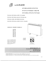
MODELOS /
MODELS~/
MODELES
AE-08
AE-12
AE-16
AE-20
AE-24
AE-28
AE-32
AENOR
Serie EXTRAPLANA
Sette EXTRAPLANA
EXPLA-FLAT Series
Serie EXTRAPLATE
lSI
Producto
Certificado
MARSAN INDUSTRIAL, S.A.
Crta. San Mart in de Valdeiglesias, Km 2,2
Tel.: 34 91 642 7020
Fax: 34 91 619 1950
28925 ALCORCON (MADRID)
MAR SAN INDUS TRIAL, S.A. se rese rva hacer cualq uier modificaci6n sin previo aviso.
MARS AN INDU STRI AL, LTD reserve the right to make modifica tions without notice.
MARSAN INDUSTRIAL,S.A. se reserve Ie droit de realiser nimporte quelle modification sans averti ssemen t preala ble.
06/03
MANUAL DE USUARIO
IMPORTANTE:
• DURANTE LAS PRIMERAS PUESTAS EN FUNCIONAMIENTO EL APARATO PUEDE EMITIR HUMOS Y
OLORES, por Lo co nviene prestar atenci6n a La ventiLaci 6n en Los primeros dia s de funcion amiento.
• LAS SUPERFICIES DEL ACUMULADOR PUEDEN ESTAR MUY CALIENTES. Las te mperaturas superficiaLes es tan
dentro de Las es peci ficac iones de las normas de seg uridad en ca lefacc i6n el ectrica , por 10 tant o un co ntac to mom ent ane o co n el
apara to no deberia ca usar les ion es. Se debera tomar precaucione s en person as ancia nas , enfer mas y nifi os q ue no esten vigilados en
las cer canias del aparato, para aseg urar qu e no se produ zcan contact os proLongados con eL acu mulador.
• SU ACUMULADOR ES MUY PESADO. Por seg uridad , NO INTENTE DESPLAZAR EL ACUMULADOR SIN UNA
PRIMERA REVISI6N DEL ESPECIALISTA. Si no esta co nfonn e co n su ubi caci 6n , por favo r avise a su instal ador .
• MUY IMPORTANTE: Cuan do no se pueda aLcan zar la temp eratura adec uada en [a habitaci6n (p.e . 20°C) normal mente es
como co nsecuenc ia de haber montado un ac umulador de potencia inferior a La que deb erfa haberse instalado, para alcanzar dicha
temp eratu ra.
• A medida que el tiernpo tran scurre pueden osc urece rse las par ed es cercanas al ac umulador, si ex iste en e l ambi ente particulas de
humo de tabaco , particulas en suspensio n, polu ci6n atrnosferi ca 0 si la pintu ra de las paredes pre sentan alto contenido en mat eri ales
plasticos.
NO CUBRA NI OBSTRUYA LAS SUPERFICIES DEL APARA TO.
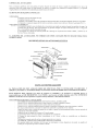
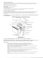
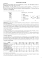
DE SCRIPCI6N DEL ACUMULADOR
1.
2.
3.
4.
5.
6.
7.
8.
9.
10.
Limitador terrnico.
Bimetal.
Caj a de Mand os.
Trampilla salida de aire calie nte
Rejill a salida aire ca liente.
Aislami ento.
En vol vent e exteri or.
Resistencia acumulaci6n .
Bloque de acumulaci 6n.
Pean a.
Fig. I
FUNCIONAMIENTO DEL ACUMULADOR
IMPORTANTE: Estas instru cc ion es de montaje deben ser lefda s cuidadosa me nte y guardada s para futuras con sult as.
El acu mulador co nsta de LadrilLos de un material refractario de altas prestaciones aislad os por una ca rn ara de aire cuida dosame nte
cstudiada. En el periodo de Tarifa Noctuma, las resi sten cias aportan al materi al refractario el calor previamente seJeccionado por el
man do de carga (ver capitulo CARGA ), liberando de spues el cal or ac um ulado du rante el di a.
Al fina l de la carga (manana) , el ca lor emi tido por e l ac umulado r es, en su mayorfa , por radiaci 6n . Esto es debid o a q ue el mater ial
refr act ario esta en el maximo de ac umulaci6n de caLor.
EI cal or emitido por eLacumuLador debe ser suficiente para satisface r las nec esid ades de ca lefacci6n de La estancia.
A medid a que el dia avanza, el calor se va tran sfiriendo paulatinamente por co nvecc i6n a la habitaci6n y la cantidad de calor liberada
em pieza a di sminui r.
AC UM ULACI6N (C ARGA)
EL co ntrol de La ac umulaci6n se efecnia medi ante el mando de carga situado en la parte superior derech a (fig. 1) de forma tot al mente
g raduab le entre el MI N. y el M AX . A may or aproximaci6n del MAX., mayor temperatura se leccio nada y mayor carga .
La ac umulaci6 n maxima se ob tiene con e l ma ndo en la posici 6n MAX. en un tie mpo de 8 hora s. La ac umulac i6n ma xima solo se ra
necesari a para tem peraturas ex teriores muy baj as. La ac umulaci6 n aconseja ble para ten er un confort deseado, se ob tiene haciendo
vari ar el mando de carga entre el MIN. y el MAX .. EI ajuste debe realizarse poco a poco, comprob ando aJ dia siguiente, si se ha
alcanzado la tem per atura dese ada . Si desp ues de la posici6n eleg ida del mand o, la temperatura de la habitaci6n no es la des eada,
m o ver el mand o .
CALEFACCl6N (D ESCA RGA )
EI acumulador a porta el cal or al local auto rnaticamente dependi end o de la ac umulaci6n deseada. C on el mando de descarg a (excep to
en eI modelo AE-08, que lleva salida automatica ) (fig. J), situado en la part e superio r, se pu ede regul ar la descarga del apa rato,
accion ando la trarnpilla de salida de aire . Con eI mand o situado en la posic i6n del MrN ., el regul ador perrnanecer a ce rrado, y el calor
se e limi na solarnente por radi aci6n y co nvecci6n a trave s de la pa redes del aparato. Esto, por sf so lo, pued e suministrar suficiente
calor en la may oria de las ocasiones y por tanto no es necesari o alte rar La posicion del m ando. Sin em bargo, si se necesita un aporte
de calor superior en el peri od o de "tarde" , entonce s se aj usta el mando a la po sici6n hac ia el MA X., con ella se lo gra ab rir la
trampill a de re gul ac i6n y se permite una salida mas rapid a de aire ca liente . Cu anto m as aprox imado este e l mando de la descarga en
la posici6n MA X. , ma s rapida es la de scarga deL acumuLador y po r tanto, e l acumulador se enfriara antes.
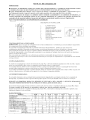
DA TOS TECNlCOS
MODELO
POTE NCIA (W)
VOLTAJE (V -)
CARGA NOMINAL (KWh) TIEMPO
CARGA 8 h
N" DE RESISTENCIAS 800 W
N° DE RESISTENC IAS 1200 W
N" DE REFRACTARIOS AE-228
N" DE REFRACT ARlOS AE-34 2
PESO SIN REFRACT ARIOS (KG.)
PESO CO N REFRACTARIO S (KG.)
I ALTO
DIMEN SIONES (nun) I LARGO
!FONDO
AE-08
AE-12
AE-16
AE-20
AE-24
AE-28
AE-32
800
230
6,4
1200
230
9,6
1600
230
12,8
2000
230
16
2400
230
19,2
2800
230
22,4
3200
230
25,6
I
----
1
2
---
I
I
3
-- -
---
4
----
8
---
4
16
56
715
463
160
---
2
I
8
4
29
125
7 15
9 19
160
to
38
715
320
160
20
77
7 15
577
160
4
4
23
91
7 15
691
160
12
---
27
111
7 15
805
160
4
----16
-- 33
145
715
1033
160
LIMPIEZA DEL ACU MULADOR
Para su limpieza superficial usese una gam uza de polvo. Durante los meses de verano, c uando el acumulador no se usa y las
superficies esten frias, puede usarse un trapo humedo. No utilizar, e n ningun caso, produ ctos de limpieza abrasivo s, y en ge nera l
ningun producto con elementos de suspension que pueda e nsuciar el entorno .
ELIMINACI6N DE PEQUENAS ANO M ALIAS
ONOCARGA:
Compr obar posicio n del rnando de carga .
Comprobar conexion a la red.
Compr obar si el limitad or terrnico de segu ridad ha desconectado. Mirar el apartado Limitador termico de seg uridad .
Si el apara to no carga por ninguno de los motivos anteriores, contacte con un Servicio Tecnico Autori zado (S.A.T.).
o NO ABRE LA TR AMPIL LA
La trampill a de salida de aire esta dotada de un mecan ismo que impide su apertura durante los periodos de carga y las
primera s horas de descarga. Este funcion arniento nos perrnite conseguir un reparto uniforme del calor a 10 largo del
dfa y evitar perdid as durante el perfodo de carga .
.
Si la trarnpill a no se abriera al fina l del perio do de la descarga en la posicion del mando en MAX ., contacte con un
Servicio Tecni co Autorizado.
LA GARANTIA DEL ACUMULADOR, NO C UBRI RA LOS DANOS CAUSA DOS POR NO SEGUIR TODAS EST As
INSTRUCCIONES,
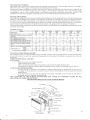
DESCRIPCI6N DETALLAD A AC UM ULADO R ESTAnco
I IMIT Ap OR Tf R MICO
MANUAL DE INSTALACION
LA INSTALACI6N DE ESTE APARATO DEBE SER EFECTUADA POR UN INSTALADOR CUALIFICADO, Y
DEBERA A,JUSTARSE A LAS DISPOSICIONES NACIONALES VIGENTES SOBRE INSTALACIONES ELEC TRICAS.
ESTE APARATO PESA MUCRO. Con objeto de manten er la estabilidad y de garantizar la segur idad futura , es
imprescindible que se FUE FIRMEMENTE A LA PARED y que las patas se hallen montadas sobre UNA SUPERFICIE
FIRME Y NIVELADA . Evitar superficies ir re gul ares del tipo alfom bras 0 determinadas baldosas.
NOTAS IMPORTANTES PARA LA INST ALACION :
NO CUBRIR NI SITUAR OBJETOS EN CONT ACTO CO N EL ACUMULA DO R.
Conservar 25 em. mfnimo de distancia en la parte superio r a cualquier co lgadura 0 estante.
Conservar 10 em. minima de espacio libre a ambo s lados del acumulado r.
Co nserva r IO em. minimo de distanc ia entre el aparato y mater iales co mbustible, tales-como cortinas y muebles.
Para mayor rendimiento del acumulador se dejara una separacio n a la pared de 25 mm. mini mo.
Despues de haber vuelto a instalar el apara to en otro lugar, se pondra en fu nciona mie nto durante el primer periodo de
carga bajo el co ntrol del instalador.
Asegiirese de que el rodapie no es mayor de 25 mm de grosor.
Si quiere dej ar fuera de servicio el apara to, desco necte lo de la instalacion.
EI tiempo de carga nomi nal de estos acumuladores es de 8 horas, y debe ser controlada por un dispositivo
programador.
Desconectar el aparato antes de realizar cua lquier operac ion en su interior.
NO ABRIR EL APA RATO ESTAN DO ESTE CARGA DO (CALIENTE).
Este aparato debera estar instalado, de forma que los interrupt ores y otros dispositivos de mando , no pueden ser
toeados por una persona que este en la bafiera 0 ducha.
3
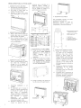
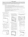
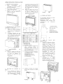
OPERAClONES PARA LA INSTALACION
distancia s que se describe en el
diagram a adj unto. Taladre la
pared , coloque los tacos y atorni lle
co n los tornill os el soporte a la
pared (mat eri al suministrado).
1.- DESMONTAJE DEL MUEBLE
1.1 Desembale el acumulado r quit ando
las pieza s protectora s inter iores.
1.2 Para qui tar el frente saq ue los
torni llos de la parte inferio r.
1.3 Despl ace el frent e hacia arr iba
basta desencajarlo de techo de
apa rato.
C ORR EC TO
e2;
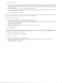
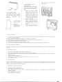
6.- ESQUEMA ELECTRICO
Este acumulador necesita una buen a
instalaci6n de tom a de tierra.
Descon ecte s iem pre el ca ble de
alirnentacion antes de acced er a los
componentes y conex iones electri ca s.
"A"
~'
~0
o
2.- DESMONTAJE DEL MUEBL E
2.1 Retir e el panel interior sacando los
torni llos que tiene en los bord es
desencajandolos del muebl e.
2.2 Con el panel interior sale el
aislarni ento termico al est ar unido
a este. Depo sitelo de tal rn anera
que no pueda dafiarse.
'~
~0
0
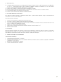
ACUMULADO RES ESTATICOS
ESQUEMA ELECTRI CO
0
~&??W~ ]
SUEL O /
MOD.
AE-08
AE-12
AE-16
AE-20
AE-24
AE-28
AE-32
Cotas en
SOL D /
A
207
285
399
513
627
777
855
mm
FLOOR /
B
c
256,5
313,5
388,5
260
H
640
640
640
640
640
640
640
3.- DESMONTAJE DEL MUEBLE
3. 1 Retir e el acondicion ador del cart6n
que sujeta las resistencias y
extr aiga de el las peanas del
apara to, los separadores de pared y
las bolsas de accesorios.
'. ~
r
-
-
----- -
1
I I
FIJACION SOPORTE A LA
PARED
4.1 Es importante que se escoj a el
metod o de fija cion apropiado para
el materi al de la pared a la que
deba fijarse
el acumu lador.
Algun os materia les moderno s de
construcci on intern a son de muy
baja
densidad
y
requi eren
d ispo sitivos
de
fijaci6n
es pec ializados para prop orcionar
una instala ci on segura y fU a.
4.2 Posicione el soporte en la pared y
marque los agujeros con las
4
' 1
I
~t---4---1 ~
.
RESISTEN CIA
LlM ITADOR TER MICO
TERM OSTATO DE CARGA
REGLETA CONE XION
.,
j
I L
T
7.- COLOCACION REFRACTARIOS
7. l . Encaje .los refractarios tras ero s
por detr as de las resistenc ias,
abatiend o estas hacia de.lante.
Primero se deb en co.locar los
bloqu es laterales y por ult imo los
centr ales. En el ca so del modele
AE-20 los ladrill os grandes (AE
342) se col ocan en e l lade
izqui erd o y en el mod ele AE-28
los lad rillos grandes se colocan en
el medio .
7.2 Coloque los refract ari os frontales
asegurandose de que apoy an
perfectarn ente
y
que
las
re sisten cia s estan bien colocadas
en el canal del aire .
7.3 Cornprobar que el mecanismo de
apertura de la trarnpill a funciona
libr em ent e, g irando a izquierd a y
dere cha el mand o de descarga.
5.3 Encaje el mueble e n el soporte por
las dos ranur as de la part e trasera .
4.-
AE-24, AE·28 , AE-32
1
2
3
4
N
5.- FIJACION DEL AC UMULADOR
5.1 Ponga las peanas al aparato en la
parte inferi or (segu n d iagrama
adj u nto) con los 4 torni llos de
cabeza
he xagonal
que
se
encu entran en la bols a de
acce sor ios.
5.2 Afl oje (no los quite) los 4 tornillos
situ ados en la trasera, 2 en cada la
teral (IM PORT ANTE: AFLO JE
LOS TORNILLOS INTERIORES,
NO LOS EXTERIORES).
AE-08. AE-12, AE- 16. AE-20 .
3
SOL
J
8.- MONTAJE FINAL
8.1
Conec tar a la toma de co niente pre vista para la TARIFA NO CTURNA . C onexiona r el ca ble de alimc ntac ion intr odu ciend ol o
por el retenedor (utilizar siernpre ca ble resistente al calor tipo HOS RR-F 0 HOS VV -F. No dej ar exceso del misrno dentro de l
apara to) . Conectar a la regleta y al torn illo de toma de tierra. Aseg iirese de que las con exi ones esran bien apretadas . Apriete e l
torni 110 del retenedor.
8.2 Intercala r entre el aparato y la instalacion electrica un interruptor de cor te .
8.3 Vu elv a a colocar el panel interior con el aislante, ASEGUR.A.NDOSE DE QUE NO QU EDE NINGUNA FISURA ENTRE
LO S AISLANTES . En samb le el mueble .
9 .- LIMI TADOR TERMICO DE S EGU RIDAD
POl' medi o de un limitador ter rnico de rearme manu al, situado en la parte intern a superior lado de rech o (dispos itivo co n un boron
roj o), co rta el funcio nam iento del ac urnu lador en ca so de un exceso de tem peratura.
Par a restab lece r el limitador terrni co :
1.
2.
3.
4 .
5 .
6 .
Asegur arse que el acumulad or es te desconectado de la tom a de co rriente.
Qu itar los tornillos situados en la parte infe rior del frontal del ac um ulado r.
Tira r hacia delante el panel fro ntal hasta qu e quede libr e del fo nda de l acumulador. Empujar hacia aniba el panel frontal , para
que se sue lte la pes tana que 10 retiene .
Pulsar e l boron rojo del limi tad or.
Colocar e l panel frontal ex terior, real izand o las o perac iones inversas a los pasos 3 y 2 .
Restablece r la toma de co rrie nte .
10.- MANTEN IMIENTO
Al sustituir cualq uier componente, debe tenerse mucho cuidado en co locar los cables, los aislantes y el bulb o del mismo mo do q ue el
ori gin al. En e l ca so de que el rnisrno ac umula do r se ins tale por seg unda vez, 6 sucesivas, las part es dafiadas 0 deteriorad as de los
aislan tes deber an ser sustituidas por partes identi cas.
11.- OBS ERV ACIONES EN C ASO DE ANOMALlAS
El acumulado r no ca lie nta nada.
1.
2.
3.
4.
Au tornatico extem o de sconectado . So lucio n: Co nec tarlo .
Comproba r limi tador terrni co, So luci6n : En caso de que se haya de scone ctado, rearmarl o (se expl ica en el apartado n''. 9)
Regul ad or de carga defectu oso, Sol uci6n : Su stituir.
Limitador terrnico defectuoso, Sustituir.
j
5
MANUAL DE UTILIZACAO
IMPORTANTE:
• DURANTE AS PRlMEIRAS VEZES QUE PUSER EM FUNCIONAMENTO, 0 APARELHO PODE EMITIR FUMOS
E ODORES, PELO QUE SE RECOMENDA QUE 0 COMPARTIMENTO ESTEJA BEM VENTILADO.
• EST E APARELHO PESA MUlTO. Com 0 objectivo de manter a estabilidade do acumulador, e irnprescindivel que se
fixe firmemente a parede 0 suporte d e parede e os pes sejam montados sobre uma superffcie firme e nivelada.
• Com 0 transcurso do tempo se 0 ambiente onde e instalado 0 acumulador e urn ambiente de fumadores, se
existem particulas em suspensao (poeira no ar), poluicao atmosferica ou a pintura das paredes apresenta urn
conteudo alto de materiais plasticos as paredes proximas ao acumulador podem escurecer Jigeiramente.
NAO TAPE NEM OBSTRUA AS SUPERFICIES DO APARELHO .
DESCRI <;AO DO AC UM ULA DOR
Limitador terrni co
Resisten cia bimetal
Painel de control
Registo de saida de ar quente
Grelha de saida de ar quent e
Isolam ent o
Carcaca ex terior
Resisten cia
Bloco de acumulacao de ca lor
Suport es (Pes)
I.
2.
3.
4.
5.
6.
7.
8.
9.
10.
M IN. C ARG A
MIN. DESC A.RGA
Fi g. 1
FUNCIONAMENTO DO ACUMULADOR
IMPORTANTE: Estas instrucoes de montagem devem ser lida s cuidadosa mente e consideram que as necessidades de aquec ime nto
do compartimen to fora rn calculadas co rrectamente.
o ac umulador e consti tufdo por bloco s de urn material refra ctario de alta performance , isolad os por uma carnara de ar
c uidadosa me nte es tudada. No perf od o da tarifa nocturna, as resis tenc ias transmi tem aos blocos refrac tarios 0 calor previarnen te
se lecc ionado pelo term ostato de carga (ver ca pitulo CARG A), lib ertand o es tes depois 0 ca lor ac umulado , durante 0 dia.
No final da ca rga (rnanha) , 0 calo r em itido pelo ac um ulado r e na sua rnaiori a, por radia cao . Isto deve-se ao fact o de os refractar ios
estarem no maximo da sua ca rga.
Este calo r ernit ido por radiacao deve ser suficiente para satisfazer as nece ssidades de aquecime nto do compa rtimento.
A medid a qu e 0 dia avanca, 0 calor vai-se tran sferindo lentamen te por co nvecc ao ao compartim ent o e a quantidad e de calo r libertada
corneca a dimi nui r.
ACUMULACAo (CARGA)
o controlo da acu rnulacao faz-se atraves do term ostato de car ga (Fig . 1) de form a totalmente gra dual entre 0 Min . E o Max.. Qua nto
rnaior for a pro ximid ade do Ma x, rnaior a a temperatura se leccionada e rn aior e a carga termi ca .
A acu mul acao maxim a, obtern-se co m 0 term ostato no Max. a carregar num periodo de 8 horas. A ac urnulacao maxim a so se ra
necessari a pa ra temper aturas ex te riores mui to baixas em relacao it temperatu ra am biente do local.
A acu mul acao aco nselhavel para obt er 0 co nforto de sejado, obtem -se faze ndo variar 0 regu lador entre 0 M in e 0 Max. 0 aj uste dev e
realizar-se pouco a pouco, verificando no dia seg uinte se ja se alcanco u a temperatura desejad a.
AOUEClMENTO CDESCA RGA)
o acu mulad or tran smit e 0 ca lor ao co mpa rtimento automatica mcn te dep end endo da acu mul acao realizad a. Com 0 regul ador de
de scarga (Fig . I) pod emos acc ionar 0 registo de descar ga par a regul ar a co nveccao desej ad a, tend o no entanto em con ta que:
DURANTE AS PRIMEIRAS HORAS DO PERIODO DE DESCARGA (P E LA MANHA ) 0 REGISTO PERMANECE
FECHADO INDEPENDENTEMENTE DA POSI<;AO DO REGULADOR DE DESCARGA.
•
Se nas ultimas horas da tarde se deseja aumentar a saida de cal or. deve-se colocar 0 regulador de desc arg a na posi cao Max. (Fig. I).
(Excepto no modelo AE-08, que por ser automatica a saida de calor , nao tern comando de descarga),
Quanto mais pr6ximo esuver 0 regul ador da desc arga da posicao Max., mais rapida e a de scarga do ac umulador e portanto, rnais
rapid amente esgotara 0 calor acu mul ado .
DADOS TECNICOS
MODELO
POTENCIA (W)
TENS AO (V - )
ENERGIA ACU MUL ADA (KWh ) EM 8 h
DECARG A
N° DE RESISTENC1AS 800 W
N" DE RESISTEN CIAS 1200 W
N" DE REFRACTARIOS AE-228
N" DE REFRACTARIOS AE-34 2
PESO SEM REFRACTA RIOS (KG.)
PESO COM REFRACT ARIOS (KG .)
I ALTUR A
D1MENSOES ( m m)
[LARGU RA
I PROFUNDIDADE
AE-08
800
230
6,4
AE· J2
1200
230
9,6
1
AE-16
1600
230
12,8
AE-20
2000
230
t6
I
I
4
4
23
91
7 15
69 1
160
-- -
2
-- -
I
---
4
----
---
4
16
56
7 15
46 3
160
8
---
20
77
7 15
577
160
10
38
7 15
320
160
AE -24
2400
230
19,2
AE-28
2800
230
22,4
AE-32
3200
230
25,6
3
2
4
- -
I
----
12
8
4
29
125
7 15
919
160
- -
27
I.JI
7 15
805
160
16
- -
33
145
715
1033
160
LIMPEZA DO ACUMULADOR
Para a Iimp eza superf icial do acumul ado r use-se um pano de po , Du rante os meses de ver s o, qu ando 0 acumulad or nao se usa e as
superficies estao frias, pode usar -se um pan o hiimido. Nao utili zar e m nenhum caso produtos de limpeza abra sivos e e m ge ral
nenhum produto com elementos de susp ensao
ELIMINA<;:AO DE PEQUENAS ANOMALIAS
NAO CAR RE GA
Verificar a pos icao do regul ador de ca rga .
Veri ficar a ligac ao a rede.
Verificar se 0 limitador terrnico de segu ranca desligou. Ver 0 capi tulo LIMITADOR TERMICO DE SEGURANc;A
Se 0 aparelho co ntinua a nao carregar, co ntacte um service tecni co auto rizado .
NAO ABRE 0 REGISTO DE DESCARG A
Este registo esta dotad o de um sistema que imp ede a su a abertura dur ante as horas de ca rga e as primeiras de de sc arga. Este siste ma
permite-nos co nseguir uma d istr ibui cao do calor de uma forma unifonne ao longo do d ia e evitar perdas durante a carga .
Se 0 regi sto nao se abre co m 0 regulador de de scarga na posicao Max. , dur ante a ultim a fase da de scarga, co ntac te um serv ice
tecnico autoriza do .
A GARANTIA DO ACUMULADOR NAO COBRE DANOS CAUSADOS POR NAO SE SEGUIREM CORRECTAMENTE
ESTAS INSTRU<;:OES.
DESCRICAO DETALHADA DO ACUMULADOR ESTATICO
ISOlAM
11
LIMiT A DO Il rEIlMI CQ
HA
_~..... ISO l AMENr:, INFt RI DIl
~BQR'fS
DE _"'OM
PES
INSTALACAO
A INSTALA<;AO DEVE SER EFECTUADA POR UM INSTALADOR QUALIFICADO.
ESTE APARELHO PESA MUlTO. Com 0 objectivo de manter a estabilidade do acumulador, e imprescindivel que se fixe
firmemente a parede 0 suporte de parede e os pes sejam montados sobre uma superficie firme e nivelada.
IMPORTANTE :
o ac um ulador deve ser mo ntado num local seco e so bre um a supe rficie plan a, hori zontal.
o assenta rnento co rrec to do ac umulado r e imp ortante, os pes de vem estar so bre um a base firme.
M ant er um minima de 25c m de d istancia da parte su pe rio r do aparelho a qualqu er o bjecto o u estante .
M anter urn minima de lOcm de d istancia de ambos os lad os do acumulador.
Manter urn minima de IOcm de d istancia entre 0 ac umulado r e materiais cornbus tfveis , tais como cortinas e moveis.
Nao co brir nem colocar objec tos so bre 0 acumulad or.
Qua ndo se reinstalar um ac um ulador noutro local de verao as primeiras horas de carga ser acompanhadas pel o
instalador.
En tregue este manual de instru coes devera ser cu idad osam ent e conserv ado e q uando hou ver rnudanca de pro pri etari o.
A instalacao deve se r realizada po r pessoa l qua ilifi cad o e de acordo co m as nor mas em vigor.
De sligar 0 aparelho da rede antes de realizar qualquer operacao no seu interior.
Nunca abrir 0 acu mulador enq uanto es te estiver ca rregado (quente) .
Es te a parelho de ver a ser instalad o de forma a qu e nao possa ser tocado pOl' um a pessoa qu e esteja nu ma banhei ra o u
chu veiro .
tempo de carga nominal do acumulador sao 8 hor as e dev e ser controlado po r urn re logio programador.
o
7
OPERA<;:OES PARA A INSTALA<;:AO
1,- DESMONT AGEM DA C A RCA<;:A
1.1 Desem bale 0 ac um ulado r tirand o
as peca s pro tectoras inter iores .
1.2 Para tirar 0 paine l in retire os
parafuso s da par te inferior.
1.3 Ret ire 0 paine ! fazend o-o desli zar
no sentido da grelha .
a pared e onde vamos fixa r 0
ac urnulador (nao usar buchas de
plas tico para fijar 0 acurnul ador ). I
L2 Pos icio ue correct arncnte a ba rra de
fixac ao na parede e marqu e 0 local
dos furos. Faca os fu ros na parede
e fixe a barr a usand o as bucha s e
para fusos q ue sao for necidos no
saco.
6.- ESQUEM A EL ECTRICO
Este acum ulado r necessita de um a
instalacao co m boa ligacao it terr a.
Desl igu e sernpre 0 ca bo de ali mentacao
an tes de ace der ao interior do
acu mulado r.
ESQUEMA ELECTRI CO
2.- DE SMONTAGEM DO PAI NE L
INTE RIOR
E
RESPECTIVO
ISOLAMI EN TO FRONTA L
2.1 Desap erte os par afuso s que es tao
nos re bord os e retire 0 pain e!
interior.
2,2 Co m 0 pain el interior sa i 0
isolarnento terrn ico. De be pou sar
se este de forma a nao dani ficar 0
isolarniento ,
P2"
A E-08, AE-12, AE-16, AE-20,
AE·24 , AE-28, AE-32
"A"
3
"C "
: : 2
4 ,- FIXA<;:AO DO SUPORT E A
PA RE DE
4 ,1 E importa nte que se escolha 0
me todo de fixacao apro priado para
8
RESISTENCIA
L1MITAOOR TERMICO
TERMOSTATO CARGA
L1GADOR
L eJ
MOD.
AE-08
AE-12
AE-16
AE-20
AE-24
AE-28
AE-32
A
207
285
399
5 13
627
777
855
B
C
.-
--
--
--
--
--
--
256,5
3 13.5
388,5
--
- -
--
260
H
640
640
640
640
640
640
640
Co tas em mm
3.- AC O ND ICIO NA M IENTO
DO
INTERIOR
3. 1 Re tire a peca de cartao q ue segura
as resi sten cias, os sep aradores de
parede e tire os suport e s e a bo lsa
de par afuso s.
1
2
3
4
5. - FIXA<;:AO DO ACUMULADOR
5, I Co loq ue os pes na parte infe rior
(conforme desenho) usan do os 4
parafusos de ca beca hexagon al
forne cidos no saco.
5.2 A1iviar (nfio os retire ) os 4
pa rafus os
situados
na
part e
traseira,
2
em , cada
lado
(IM PORTANT E: ALIVIAR OS
PARA FUSOS
INTERTORES,
NAO OS E XT ERTORES) ,
5.3 Encai xe 0 apare lho no supor te de
parede usando as ranhuras na
traseira do mesrno.
r
-
-
-- --- -
.,
I
I
I
I
I
I
N~t - - -4- ---lJL
T
7.- COLOC A<;: AO DOS
RE FR ACT AR IOS
7.1 En ca ixe os ref racta rio s trasei ros
por
tras
da s
resisten cias,
re baten do-a s para a fre nte. E
acons elh avel colo car pri mero os
dos extremo s. No caso do model o
AE-20 os refractarios grande s
(AE-3 42) sao co !ocado s no lado
esq uerdo e no mod elo AE- 28 os
refractari os gra ndes sao colocados
no centro .
7.2 Co loque os refractari os fron tai s
asseguran do-se de que estes estao
bern
apoiados
e
qu e
as
resistencias estao be rn colocadas
no ca nal de ar.
7,3 Verificar qu e 0 regist ro de
abertura fu nc iona
Iivre rnente,
gira ndo 0 botao de de scarg a par a
a esq uer da e para a direita.
8.- MONTAG EM FINAL
8.1 Ligar 0 cabo de alirnentacao introdu zindo -o pe lo retentor (utilizar sempre cabo de ligacao tipo H05 RR-F ou HQ.5 VV-F . Nao
deixar excesso do mesmo dentr o do apar elho). Ligar 0 ca bo de terra no parafuso de tomada corres ponde ntc. Verifica r que as
Iigacoe s estao todas bem ape rtadas e apertar 0 parafuso do retentor.
8.2 Verifique que as Iigacoes (termina is) das resistencias estao bem enca ixados.
8.3 Intercalar en tre 0 aparelho e a instalacao electrica um interrupter de co rte.
8.4 Volle a co locar 0 isolame nto fro ntal e 0 painel, asseg urando-se que nao se enco ntra partid o. Recoloqu e 0 pain el frontal.
8.5 Nu nca insta le 0 acumulado r sobre ou por baixo de uma tom ada .
9.- Ll MIT AD OR T ER MI CO DE SEGURAN<;A
Por meio de urn lim itador termico de rearm e manu al, situado na part e intern a superior, co rta
caso de excesso de temperatu ra.
Para rearrnar 0 limi tador termico :
l. Cert ifique-se de que 0 acum ulador esta desligado da rede elec trica.
2. Siga as instrucco es de instalocei: para ret irar 0 painel fro nta l.
3. Carregar no botao verme lho do limitador termi co.
4. Mon te de novo 0 painel fronta l.
5. L igar 0 acum ulador de novo a rede .
0
funcionamien to do acurnulador em
10- MANUTEN<;AO
Ao substituir qualquer compone nte, debe ter-se muito cuidado ao colocar os conductores, os isolamentos e todos os mecani smos da
mesma form a que se encontravarn originalmente. Qu ando urn acurnulador for reinstalado uma ou mais vezes os isolam en tos
deteriorados de vern su bsti tuido s por novo s iden ticos ,
11.- OBSERVA<;OES EM CASO DE ANO MALIAS
o acumulador nao aque ce nada.
I
2
3
4
Nao chega corre nte ao acum ulador. Verificar se 0 relog io nao es ta a co rtar 0 circuito e se nao ha problemas com a alim entacao
electrica.
Verificar se 0 limit ador terrnico foi activ ado , Nesse caso, rearrnar (seg uindo as indi cacoes do capitulo "LIMIT ADOR
TERMICO DE SEGURAN <;A".
Terrno stato de ca rga defeituoso. Substituir.
Li mitad or terrn ico defeituoso. Subs tituir.
USER'S MANUAL
IMPORTANT:
• During the fir st occasions the appliance is sta r ted, it ma y release smoke and smells, for which reason the roo m should be
well ven tilated.
• This appliance ha ve ver y hot su r fa ces. ATTENTION
• This appliance weights a lot. In order to maintain its stability and guara ntee futur e safe ty, it is vital to fix it firml y to the wa ll
and fit the stands upon a firm, le vel surface.
• With time. the walls near the acc umulator ca n darken if there are tobacco smoke part icles in the enviro nment, or there are
particl es in suspension. atmospheric poll ution or if the wall paint has a high plastic co ntent.
DO NOT COVER OR OBSTRUCT THE SURFA CES OF THE APPLIANCE
DESCRIPTI6N OF THE STORAGE HEATER
I.
2.
3.
4.
5.
6.
7.
8.
9.
10.
Thermal limiter.
Bimeta l.
Cont rol' s panel.
Hot air outlet flap .
Hot air outlet grid.
Insul ation.
Outer cas ing.
Heat storage resistance .
Heat storage block .
Sta nd .
MIN. DESCARG A
MIN. C ARG A
{ I) { I)
Fig.
FU NCTIONING OF THE STORAGE HEATER
IMPORTANT : These assembly instruc tions must be care fully read and it is takenfor gra nted that the heating needs of the room
have been corr ectly calc ulated.
Th e storage heater consists of hig h performance refr actory bricks insulated by a carefully studied air chamber. Du ring the Noctu rnal
Rate, the res istances give the refractory material the heat pre viously selec ted on the charge con tro l (see cha pter CHARGING) ,
afterw ards releasing this accu mulated heat duri ng the day. At the end of the charging (mor ning) . the hea t emi tted by the storage
heater is mostly through radiatio n. Th is is due to the fact tha t the refractory mate rial is at th maxi m um heat storage rate. Th e heat
released by the stor age heater must be suffic ient to satisfy the heating need s of the room . As the day adva nces, the heat is gra dually
tra nsfer red around the roo m by co nvectio n and the quantity of heat freed beg ins to d imin ish.
9
l '
HEAT STORAGE (CHARGING)
Heat storage control is carr ied out by mea ns of the totally adj ustab le control kno b (Fig. I) between MIN . and MAX . The neaner to
MAX .. The nearer to MAX., greater is the temperatur e selected and greater the charging.
Maximu m heat storage is obtained with the control knob at the MA X. position in a time of 8 hours. Maximum heat stora ge will only
be necessary for very low outdoor temperature s and in relati on to the atm osph eric temp erature of the room . The heat storage
reconunended in order to achieve a desired co mfo rt is that obtained by moving the control knob between MIN . and MAX. T his
adju stm ent must be carried out gradua lly, checking the next day to see whether the des ired temper ature has been reached.
HEATING mISCHARGING)
The sto rage heat storage gives heat to the room automatically depending upon the heat storage carried out. With the disch arge control
knob (Fig. I), the discharging of the appliance can be regulated , ac tivating the air outlet flap door, bur always bearing in mind that:
Durin g the first hour s of the d ischar ging period (in the morn ings), the flap door remai ns closed inde pendently of the MAX. position .
If an increase in heat output is required during the last hours of the eve ning, situate tbe discharge control knob (Fig. I) at the MAX .
position (exce pt in model AE-08, which , being the heat outlet automatic, the appli ance does not a discharge co ntrol knob) .
T he nearer the discharge con trol knob is to the MAX . position, faster is the discharging of the storage heat er and therefore the storage
heater coo ls down quicker.
TECHNI CAL DATA
MODEL
POWER (W)
VOLTAGE (V-)
NOMINAL CHARGING (KWh) 8 h HOUR
CHARGE
W OF RESISTANCES 800 W
WOF RESISTANCES 1200 W
W OF REFRACTORY BRICKS AE-228
W OF REFRACTORY BRICKS AE-342
WEIGHT WITHOUT REFRACTORIES
(KG.)
WEIG HT WITH REFRACTORIES (KG.)
I HIGH
DIMENSIONS (rnm)
I LONG
I DEEP
AE-08
800
230
6,4
AE-12
1200
230
9,6
1
AE-16
1600
230
12,8
AE-20
2000
230
16
AE-24
2400
230
19,2
AE-28
2800
230
22,4
AE-32
3200
230
25,6
--- -
2
1
3
2
4
- -
1
---
I
---
I
-- -
4
----
8
---
---
8
4
29
---
20
4
4
23
- --
10
4
16
38
7 15
320
160
56
715
463
160
77
7 J5
577
160
91
715
69 1
160
125
715
919
160
145
715
1033
160
12
27
III
7 15
805
160
16
33
CLEANING OF THE STORAGE HEATER
For cleaning the surface , use a chamo is leather. During the months of summer, when the storage heater is not used and heat surfaces
are co ld, a wet clo th can be used . Never use abra sive cleaning produ cts or any product with elements in suspe nsion that can dirt y the
environme nt.
CORRECTION OF SMALL FAILURES
o NO CH ARGE:
Che ck the position of the charge con trol knob .
C heck connec tion to the current.
Check if the safety therm al limiter has disconnected. Look at the section Safety Thermal Lim iter.
If the appliance still does not char ge for the abov e-me ntioned reasons, cont act An Autho rised Tec hnical Service.
o THE FLA P DOOR DOES NOT OPEN:
T his fl ap doo r has a mec hanism which impedes its openin g during period s of char ging and the first hours of
discharging. This function allows us to achieve a uniform sha re of heat throughout the day and avoid loss during the
char ging perio d.
If the flap door does not open with the disch arge control kno b at the MAX . positi on during the fina l phase of
discharging, conta ct an Authorised Technical Servi ce.
THE GUARANTEE OF THE STORAGE HEATER DO ES NOT C O VE R ANY DAMAGED CAUSED BY NOT
FOLLOWING ALL THESE INSTRUCTIONS.
DETAILED DESCRIPTION OF STATIC STORAGE HEATER
r
HA R
TH Q H
TA T
pp P IN
ATI
10
N
INSTALLATION
THE INSTA LLATION M UST BE CARRIED OUT BY A QUALIFIED INSTALLER. THE INSTALLATION MUST BE
CARRIED OUT BY QUALIFIED PERSONNEL AND IN COMPLI ANCE WITH THE CURRENT NORMS STANDARDS.
Thi s appliance weighs a lot. In order to maintain its stability and guarantee future safety, it is vital to fix it firmly to the wall
and fit the stands upon a firm , level surface. The storage heater must be placed in a dry area and on a l1at, horizontal surface.
The correct positioning of the storage heater is important, the stands having to be on a firm base.
IMPORTAN TS NOTES :
Keep a 25 e m . minimum distan ce fro m the upper part to any hang ing obj ect or shelf.
Keep a 10 em. free space at both sides of the storage heater.
Kee p a 10 em. mi nimum distance between the appliance an d co mbustible material, such as c urta ins and furn iture.
DO NOT COVER THE STORAGE HEATER O R PLAC E OBJECTS IN DIRECT CONTACT WITH IT .
For the best fun ct ion ing of the storage heater , a 25 m m. minimum se para tio n from the wall mu st be left operat ing.
After having rein stall ed the ap pliance in a differ ent pla ce, it must be s tarte d up und er the co ntro l of an au thorise d
installer during the first peri od of c harg ing.
Th is instruction ma nual should be carefully ke pt and when there is a change of owner, it must be giv en to the new
user.
If yo u wish to leave the applian ce o ut of se rvice , disconnect it from the install ati on .
Th e nominal c harg ing time of these storage hea ter s is 8 hours a nd mu st be controJled usin g a timer de vice.
Disconnect the appliance before undertaking any intern a l ope ration.
Do not open the app liance if it is c harged (very hot).
Thi s appliance must be installed so that the sw itches and o the r co ntrol de vices cannot be tou ched by a nyb od y wh o is
in the bath or sho wer.
' A'
INSTALLATION INSTRUCTIONS
1.- UNPAC KING THE DEVICE
1.1 U npack the storage hea ter by
removin g the inne r protec tive
parts.
1.2 To remo ve the front, ta ke out
the screws from the lower part .
1.3 Turn the front upwards un til
removin g it fro m the top of the
applia nce .
2.- INTERNA L COVER AND
INS ULATION REMOV AL
2. I Remove
the fro nt pan el by
taking out the sc re ws it has at
the edges, extra ct ing it from the
de vice.
2.2 T he thermal insu.lation co mes
o ut with the front pan el as it is
jo ined to th is, a nd must be laid
dow n carefull y in such a way
that it is not dam aged .
3.- INT ERN AL PREPARATIONS
3. 1 Remo ve the a ir co nd itio ne r fro m
the car db oa rd box that fastens
the resistances and take the
stands of the appliance out of it,
the wall separators and the bag
o f acce ssor ies.
4 . FIXTURE OF THE S UPPORT
TO THE WALL
5
It
is
im por tant that
the
appro piate fasten ing de vice is
c hos e n fo r the mat eri al o f the
wall to whic h the stora ge heater
is going to be fixed , Some
modern internal con stru cti on
materials are of very lo w
th ickn ess and require fastening
de vices w hich are spe cia Jise d in
order to give a secure and stable
installation.
6
Position the support on the wa ll
and mark the holes, m ak e drilJ
holes in the wa ll and sc re w in
the su ppo rt wi th the plu gs and
lag screws sup pli ed in the bag of
ac cessor ies.
o
0
0
O~
0
~ffff
///4'ff////4W/07ffffi'fftW#I$
fl'E/ffg~
/
SUE Lo
I
SOLO
FLOOR / SOL
I
MOD.
A
B
C
AE-08
AE- 12
AE-16
AE-20
AE-24
AE-28
AE-3 2
207
285
399
5 13
627
777
855
--
256,5
3 13,5
388,5
--
- --
--
--
--
--
260
--
--
H
640
640
640
640
640
640
640
Dimensions In mm.
5.- FIXATION OF THE STORAGE
H EATER
5. J Put the stands of the appliance
on the lo wer part (accor d ing to
the att ach ed diagram ) w ith four
hexagon al head screw s which
can be found in the bag of
accesso ries.
5.2 Loosen (do no t take o ut) the 4
screws located at the back, 2 on
each side (important: Loosen the
insid e sc re ws, no t the o uts ide
on es).
~
~
~~
.r
t
5.3 Insert the de vice int o the suppor t
throu gh the two g rooves at the
rear part.
II
free ly, turn ing the d isch arge co ntro l
left and right.
~
CORRECT
6.- ELECTRIC SCHEMA
Th is storage heater need s a good
earth installatio n. Alw ays disconnec t
the power cabl e before acc ess ing
ele ctri cal
co mpo nents
a nd
connecti ons.
ELECTRI C DIAGR AM
AE-08. AE-1 2, AE-1 6. AE-20,
AE -24. AE-28 . AE-32
1
2
3
4
RESISTAN CE
THERM AL LIMITER
CHARGE THERM OSTAT
CO NNECTING STRIP
7.- REFR ACTORY BLOCK
INSTALLATION
IMPORTANT: Meti culously cle an
the refr actory blocks of du st and dirt
bef ore fitting them int o the storage
heater
7 .1 Insert the rea r heat resi stant
block s behind the resistances,
pu shing these forw ard. It is
ad visabl e to place those at the
end s first. In the ca se of the
model AE- 20, the bi g brick s are
to be put o n the left side and in
the mod el AE- 28; the big bricks
are put in the middle.
7 .2 Position the front he at resi stant
blo cks, ensuri ng that the y rest
perfectly and th at the resist ance s
are correct ly placed in the air
c hannel.
7 .3 Che ck that the flap door
o pe nning mech ani sm fun cti on s
T
8.- FINAL ASSEMBLY
8.1 Con nect the pow er ca ble introdu ci ng it int o the retainer (alw ay s use po wer ca ble type HOS RR-F or HOS VV -F. Nev er leave an
ex cess of it ins ide the appliance .
8.2 Insert a pow er cu t sw itch between the appli ance and the electric install ation.
8.3 Replace the insul ati on and inner pan el , makin g sure that no cr ack is left. A ssemble the dev ice .
8.4 Do no t install the appliance below a sw itch block.
8.S Mak e sure that the resistan ce co nnec tio ns are firml y fixed .
8.6 Connect to the connection strip and earth. Check the con nections are we ll co nnected . Ti ghten the retainer scr ew.
9.- SA FET Y TH ERMAL LIMITER
By mea ns of the manu al resett ing therma l limiter, situated in the upp er inner part , the sto rage heat er is c ut off in case o f an e xce ss of
temperature.
T o reset the thermal limiter:
I .
2.
3.
4 .
S.
6.
En sure that the storage heater is disconnected from the curre nt.
Remove th e screw s sit uated in the lower part of th e fro nt of the storage he ater.
Pull the front panel forward until the bott on of the sto rage heater is freed . Pu sh the front pan el upw ard s, in order to release the
flan ge ret aining it.
Pu sh the red thermal limiter butt on .
Replace the out er front pan el, carrying out the inverse ope ratio n as in steps 3 and 2 .
Re- establi sh the current.
10.- MAINTENANCE
On sub stituting any co m pone nt, great care must be taken in placing the cables, the insulation s and the bulb in the same way as the
o riginal s. In the case that the storag e heater is installed for a second or success ive time, the dam aged or det eriora ted parts of the
insulation s mu st be replaced by identical co mpo nents.
I 1.- REMARKS IN C AS E OF FAILURE
Th e sto rage heater do es not hear up a t all.
I . Outer aut omati c disconnected. Connected it.
2. Che ck thermal limiter. (I n the case tha t it has been disconnected , reconne ct it. Thi s is ex plained in the sectio n SA FE TY
THERMAL LIMITER .
3. Faul ty chargin g regul ator. R epl ace it.
4 . Fault y thermal limiter. Replace it.
12
MANUEL DE L'USAGER
IMPORTANT:
• AU COURS DES PREMIERES MISES EN FONCTIONNEMENT, L'APPAREIL PEUT EMETTRE DES FUMEES ET
DES ODEURS. La piece devra, pour aut ant , etre bien ventilee.
• CET APPAREIL EST TRES LOURO. Dan s Ie but de maintenir sa stabilite e t de garantir la securite future, il est
indispe nsable de le fixe r ferrnerne nt au rnur et qu e les patt es so int montees sur une surface ferme et nivelee.
• Au cour s des ans, les murs situes pres de I' accumulateur pourraient devenir plu s fen ces , si dan s ['air ambiant il y a
des particules de furne e de tabae , partieule s en suspensio n, pollution atrnos pherique ou si la peinture des murs a un
eontenu elev e de matieres plastiques.
NE PAS COUVRIR NI OBSTRUER LES SURFACES DE L 'APPAREIL.
DESCRIPTI6N DE L ' ACCUMULATEUR
I.
Limite ur then ni q ue .
Bimet al.
3. BOlte de co rruna ndes .
4. Trappe so rtie d 'air c ha ud
5. Grille so rtie air cha ud .
6. Isolemen t.
7. En veloppe exterieu re.
8. Resi stan ce acc umulation.
9. Bloc daccumulatio n.
10. Socle.
2.
MIN . O£ SC AP:GA
MIN. C A R G A
'CD
Fig . I
FONCTIONNEMENT DE L'ACCUMULATEUR
IMPORTANT: Lire so igneusement ce s instru cti on s de montage; davance o n considere que lon aura calcule correcternent le s
besoins de ch auffag e de la piece.
L 'ac c umulate ur com prend de s briques en mate riau refractaire a hautes pre stati on s, isolee s par une cha mbre a air so ig ne use me nt
etudiee . Ped ant la peri od e de Tarif Nocturne. le s resistan ces a ppo rte nt au materiau refr actaire la chaleur ant erieurernen t se lec tio nnee
par la co mmande de charge (vo ir chapitre C HA RG E), et libereront en suite ce tte ch aleur acc um ulee pendant Ia j ourn ee . A la fin de la
charge (Ie ma rin), la c ha leur ernise par laccumulateur se fait, en g rande parti e, par radi ati on. Ceci est du a ce q ue Ie mate riau
refract aire se trou ve a so n ma ximum daccumulatio n de c haleur. La cha leur ernise par laccumulateur doit etre suffisan te pour
satisfa ire les beso ins de chauff ag e de la piece. A mesure que Ie jour avan ce, la cha leur est tran sferee peu a peu par co nvec tion a la
piece et la q uantite de chale ur liberee com men ce ad iminuer.
ACCUMULATION (CHA RGE )
Le controle de lacc urnulation seffectue au moyen de la co mmande (Fig. I) de facon to talement reglable entre le MLN. et le MAX.
Plus on sapproache du Max., plus on selecti onne de te mpe rature, et pour autant, plu s de cha rge.
L'accumu lat ion max ima es t obtenue avec la co mma nde e n position MAX. pendant une duree de 8 heures. L ' accu rnulati on max ima
ne sera necessaire qu e pour de s temperatures exterieures tres basse s et e n fon cti on de la temperature ambie nte du local.
L 'a ccumulation co nse illee pou r o bte nir le co nfo rt de sire so btient en fai sant var ier la co mma nde e ntre Ie MIN. et Ie MAX . Le reglage
de vra se faire peu peu . e n verifian t Ie lendemain si on a a tte int la temperature desiree.
a
CH A UFFAGE (DECHARGE)
L ''accu mul ateur apporte la chaleur au loc al automa tiq ue ment selon laccurnulation rea lisee . Avec la commande de decharge (Fig. I)
on peut regler la de ch arge de lappareil en ac tio nna nt la trappe de sortie dair, toutefois en tenant toujours co mp te qu e : Pedant les
premieres heures de la periode de decharge (Ie ma tin) la trap pe reste fermee ind ep end arnment de la position du M ax. Si au co urs des
dernieres heur es de lapres midi on desire aug mente r la sort ie de chaleur, pla cer la co mmande de decharge (Fi g . I) sur la position
MAX. Sauf pour Ie modele AE-OS 2qui, possedant une sortie de chaleur automatique, na pas de commande de decharge),
Plus la com man de de decharge se trouve proch e de la posit ion MAX., plu s la de ch arge de laccurn ulateur est rap ide , et pou r autant,
laccu rnulate ur se refro id ira plu s tot.
DONNEESTECHNIOUES
MODELE
PUI SSANCE (W )
VOLTAGE (V -)
CHA RGE NOMI NALE (KWh) TEMPS
CHARGE 8 h
N" DE RESISTANCES 800 W
N" DE RES ISTANCES 1200 W
N" DE REFRA CT AIRES AE-228
N" DE REFRACTA IRES AE-342
POIDS SANS REFR ACT ArRES (KG. )
POIDS AVEC REFR ACT AIRES (KG.)
I HA UTEUR
DIMEN SIONES (nun) I LONG UEUR
I FOND
AE-08
AE-12
AE-16
AE-20
AE-24
AE-28
AE-32
800
230
6,4
1200
230
9,6
1600
230
12,8
2000
230
16
2400
230
19,2
2800
230
22,4
3200
230
25,6
1
I
I
4
4
23
91
7 15
69 1
160
3
2
1
8
4
29
125
715
9 19
160
- --
2
---
I
---
4
- --
8
- -
4
16
56
7 15
463
160
---
10
38
7 15
320
160
20
77
7 15
577
160
- -
12
---
27
111
715
805
160
4
-- -16
-- 33
145
715
1033
160
NETTOYAGE DE L'ACCUMULATEUR
Pour so n nett oyage superficiel, util iser un chiffo n pou ssiere. Pendant les moi s d'ete, q uand o n n'utilise pas I'accu mul ateu r e t que les
surfaces sont froid es, on peut utiliser un chiffo n humid e. N'utiliser en aucun cas de s produits de nettoyage abr asifs, et e n ge neral
aucun produit co ntena nt des elements en suspension q ui poirrait polluer I'environnemen t.
a
13
ELIMINATION DE PETITES ANOMA LI ES
o LA CHARGE NE FONCTION NE PAS:
Verifie r La position de La co mmande de charge .
Veri fier La con nexio n au co urant electrique.
Veri fier si Ie limiteu r thermique de securite a ete deconnec te, Voi r Ie paragraphe Limiteur the rmique de securite.
Si l'appareil ne charge pas a cause des motifs d ifferents des anterieurs , prenez conta ct avec un Servicie Tec hnique
Accredite.
o LA TRAPPE NE S'OUVRE PAS
Cette trappe es t do tee d'un mecani sme qui ernpeche son ouvertu ne pendant les peri odes de charge et les premieres
heur es de dec harge . Ce fonctionnement nous penn et d'ob tenir une repartition uniforme de la chaleu r tout au long de la
journee et d'evi ter des pertes pend ant la peri ode de charge.
Si la trapp e ne s'o uvrai t pas quand la co mma nde de dec harge se trou ve en positi on MAX. pendant la de rnie re ph ase de
la dech arge, prenez co ntac avec un Servi ce Tec hnique Acc redi te.
SI TOUTES CES INSTRUCTIONS N'ONT PAS ETE SUIVIES, LA GARA NTIE DE L' ACCUMULATEUR NE
COUVRIRA PAS LES DOMMAGES CAUSES.
DESCRIPTION DETAILLEE DE L'A CCUMULATEUR STATIQUE
T
RM
T AT
. H A l?
1'1 NT
M NT P
A R
A '"RA
"
t
R
A
" FR A TAIR
P
N
A
I Nr " R I
R f
N1A
M N1 FR
NT A
INSTALLATION
L'INSTALLATION DOlT ETRE EFFECTUEE PAR UN INSTALLATEUR QUALIFIE.
Cet appareil est tres lourd, Dans Ie but de maintenir sa sta bilite et de garantir la securite future, iI est indispensable de Ie
FIXER FERMEMENT AU MUR et que les pattes soient montees sur une SURFA CE FERME ET NIVELEE.
L'accumulateur devra et re situe dans un endroit sec et sur un e surface plane horizontale. L'assise cor recte de I'accumulateur
est importante, les socIes doivent etre PLACES SUR UNE BASE FERME.
IMPORTANT:
NE PAS COUVRIR NI PLACER D'OBJETS EN CONTACT AVEC L'ACCUM ULATEUR.
Conserver au mi nimun 25 em de di stance a sa partie supe rie ure de n'importe quell e etagere ou tenture.
Conserve r 10 em minimum d'espa ce libre de cha que co te de I'accumulateur.
Co nserver 10 em minimum de distance entre I'appareil et les materiaux co mbustibles, tels que les rideaux et les
meu bles.
Pour un rendement superieur de I'accumulateu r on devra laisser une separation de 25 em minimum du mu r.
Apres avo ir reinstalle l'app areil dans un autre endroit, on Ie ferea fonctionnn er pend ant la premiere periode de charge
sous le co ntrole de l'install ateur.
Ce manue Ld'instructions sera soigneusement garde et en cas de changeme nt de proprietai re, on Ie remetra au nou vel
usager.
Quand on des ire laisser l'appareil hors de serv ice, Le deco nnec ter de I'install ation.
Le temps de charge nominal de ces accu mul ateu rs est de 8 heures et doir etre co ntrole en utili sant un dispositif
pro gramm ateu r.
L'installation se fera par du personnel qualifie et co nfor me rnent aux normes en vigueur.
Decon necter l'appareil avant de realiser n'imp orte quelle operation dans son interi eur.
NE PAS OUVRIR L'APPAREIL QUAND CELUI-CI EST CHARGE (CHAUD).
Cet appare il dev ra etre installe de facon a ce qu 'une personne se trouvant dans une baig noire ou so us la douche ne
puisse pas toucher les interrupteurs et les autres disposit ifs de co mmande.
14
OPERAnONS POUR L'INSTALLAnON
1.- DEMONTAGE DU MEUBLE
1.1 Sortir
l'ac cumul ateur
de
I'ernballage e n e nle vant le s p iec es
p rotectrices interieures.
1.2 Pour en le ver Ie front , enveler les
vis de la parti e inferieure.
1.3 Depla cer Ie front vers Ie haut
ju squ'a ce q u'il soit deboite du
plafond de I'ap par ei l.
construct ion inte rne ont une tres
basse den site et requierent des
di sp o sitifs de fi xation specialises
afi n pr op o rtionn er une fixation
sure et fi xe .
Pl acer le suppo rt s ur le mur et
rnarquer le s trou s; percer le mur
et vi sser le su pport a vec les
c hev ille s et les tire-fonds foum is
dan s Ie sac d'accessoires.
4 .2
~
6.- SC H E M A ELECTRIQUE
C et acc um uJateur necessite un e bonne
in st all ati on de prise de terre.
Deconn ecter
toujours
le
ca b le
d' alimen tati on avant d'ac ceder aux
composants
et
au x
conn e xion s
elec triq ues.
SCHEMA ELECTRIQUE
2 .- DEMONTAGE DU C O U VE RC LE
INTERlEUR ET ISOLANT
2.1
Enlever Ie panne au fro ntal en
enlevant les vi s qui se trouvent
sur les bords en le deb oitant du
meuble.
2 .2 L'i so lemen t ther miq ue sort avec
Ie panneau fro nta l car ils so nt
uni s ; Ie deposer d e tell er facon
qu'il ne pu isse pa s etre abirn e .
0" 0
'1
~
;
AE·08 , AE-12, AE-16, AE·20.
AE-24, AE-28, AE-32
o
0
0
O~
0
SU[ LO / SOLD / FLOOR
I
4 .- FIXATION DU S UPPO RT AU
MUR
4 .1 II es t im portant de cho isi r Ie
di sp osit if de fixat ion ap pro prie
au materi au du mur ou de vra etre
fixe
l'accumul ateur, Certains
materi au x
mod ernes
de
RESISTANCE
L1MITEUR THERMI QUE
THERMOSTAT DE CHARGE
BARRETIE DE CONNEXION
SOL
MOD.
B
C
H
A
--
- 640
AE-08
207
--
AE-12
640
- 285
--
AE-16
640
- 399
- .
AE-20
256 ,5
640
513
--'
640
AE-24
627
313,5
--
AE-28
640
777
388,5
260
640
AE-3 2
- 855
Dimension s en rnm
5.- FIXATION DE
L'ACCUMULATEUR
S.I Pl ac er les socl es de I'appareil
la
parti e
inferi eure
(selo n
Ie
diagrarnrne c i-jo int) avec les 4 vis
te te he xagon ale qu i se trou vent
d an s Ie sac d 'accesoires .
5 .2 Desserrer (ne le s enlevez pa s) les 4
vi s situees sur larriere, 2 chaq ue
cote (IM PO RT AN T:
DESS ERRER LES VIS
INTERI EURES, PAS LES
EXTERlEURES) .
a
AMEN AG E M EN T
DE
3 .L 'JNT E R IE U R
3 .1. Enle ver le suppo rt de carto n qui
soutient les resi stan ces et en so rtir
les socles de l'a p pareil, les
separateurs de mu r et Ie sac
d'accessoires .
.: : 2
~$$/l$/410W$~
1
2
3
4
a
a
5.3 Emboit er Ie me uble sur Ie support
p ar Ie s deu x rainures de la partie
arrie re ,
.I
I
...,
- - - - ---I
I
I
I
N~ r-- -4----t
T
7 .MISE
EN
PLACE
DES
REFRACTAIRES
7 .1 Emboiter les refract air es arri e ve,
derriere Jes resistance s e n a ba tta nt
ce Jles-ci vers l'av ant. Il est
co nseille de situ er d' ab or d ceux
des extrernites. Dans Ie ca s du
mode le AE- 20 les gran de s br iques
(A E-3 42) se placent s ur Ie cote
gauc he e t dans Ie modele AE-2 8
les grandes briques se pl acent au
rni lieu .M ettre
en
pl ace
le s
refractaires frontau x en sassu rant
qu' ils s'appuie nt parfaitemen t et
que les resistances so nt bien
placees dans Ie canal de l'air.
7 ,2 Verifier
que
Ie
m ecani sme
d' ou verture
de
Ia
tra ppe
fon ctionne librerneru, e n faisan t
tourner ve rs la ga uc he el vers la
droite Ia com ma nde de dech arge .
8.- MONTAGE FINAL
8.1 Connecter le cable d'alimentation en J'instroduisant par Ie retenteur (toujours utili ser du cable d'alimentation de type H05 RR-F
ou H05 VV-F. Ne pas Iaisser d'exce s de ca ble a l'interieur de l'appareil ). Connecter a la barrette et a la vis de prise de terre .
S'assurer que les connexions sont bien serrees, Serrer la vis du retenteur,
8.2 Intercaler entre I'appareil et I'install ation electrique un interrupteur de coupure,
8.3 Remettre en place I'isolant et Ie panneau interieur, en s'ass urant qu'il ne reste aucune fissur e. Assembler Ie meu ble .
8.4 Ne pas installer I'appareil sous une base de prise de courant.
8.5 S'assurer que les connexions des resistances sont ferm ement fixees,
9.- LIMITEUR THERMIQUE DE SECURrm
Par le biai s d'un lim iteur the rrnique a rearmernent manuel , situe 11 la partie interne superieure, couper Ie fonctionnement de
I'accumulateur en cas d'exce s de temperature .
Pour retablir le limiteu r thermique:
1.
2.
3.
4.
5.
6.
S'assurer que I'accumulateur est deconnecte de la prise de courant.
Enveler les vis situees 11 la partie inferieure du frontal de I'accumulateur.
Tirer vel'S l'avant Ie panne au frontal ju squ'a ce qu 'il soit libere du fond de l'accumulateur. Pou sser Ie panneau frontal vel'S Ie haut
pour qu' il se defasse de la languette qui Ie retient,
Appuyer sur Ie bouton rou ge du limiteur therrnique.
Mettre en place Ie panne au frontal ex terieur en reali sant l'operation inver se des points 3 et 2.
Retabl ir la prise de co ura nt.
10.- ENTRETlEN
Qu and on substituera n'importe quel composant, il faudr a faire tres attention de rernettre les ca bles , Ies isolants et Ie bulbe de la
merne facon que sur I'original. Au cas ou Ie merne accurnulateur serait installe pour la sec onde fois, ou des fois succ essives, les
parties abimees ou deteriorees des isolant s devront etre sub stituees par des parti es identiques.
11 .- OBSERVATIONS EN CAS D'ANOMALIES
L'accumuJateur ne chauffe pas.
I.
2.
3.
4.
Automatique externe dec onnecte. Le connec ter.
Verifier Ie limiteur thermique. (Au cas ou i! aurant e te deconnecte, Ie rearrner; (ce la est ex plique au para graphe du LlMITEUR
THERMIQUE D E SECURlTE)).
Regulateur de charge defectueux, Substituer.
Limiteur therm ique defe ctueux . Sub stituer.
,
16