1
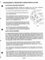
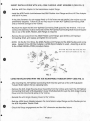
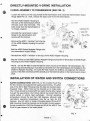
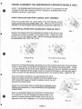
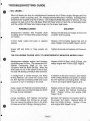
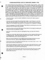
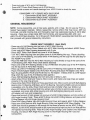
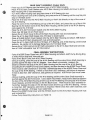
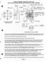
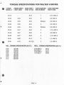
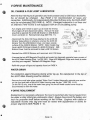
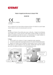
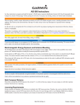
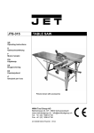
If•A!
V-DRIVE
INSTALLATION & SERVICE MANUAL
-- Models RV-10 & RV-10D thru RV-50 & RV-50D --
•
WARNING !!! Do not touch V-Drive or related components until all shafts and exposed parts
are stopped, the ignition is off, the battery is disconnected, and the propeller shaft is locked.
All repairs and maintenance must be done by a skilled mechanic. No work should be performed
unless the mechanic is equipped with steel-tipped shoes and protective eyeglasses or goggles.
Other sensible precautions should also be taken.
•
PAGE # CONTENTS
Independently-Mounted V-Drive Installation
1
Directly-Mounted V-Drive Installation
3
Installation of Water & Switch Connections
3
Oil Fill
4
Alignment Instructions
5
Troubleshooting Guide
7
Disassembly & Reassembly Instructions
10
Pump Assembly Instructions
13
Torque Specifications
14
V-Drive Maintenance
15
Independently-Mounted General Assembly Print
16
Directly-Mounted General Assembly Print
18
THE WALTER MACHINE COMPANY, INC.
84-100 CAMBRIDGE AVENUE
JERSEY CITY, N.J. 07307
TEL: (201) 656-5654 •
FAX: (201) 656-0318
WARRANTY AUTHORIZATION: All warranty work must be authorized by the factory before being performed. Consult
W.M.C. with the V-Drive serial number and model number to be given a warranty authorization number. No warranty
claim can be honored if prior authorization has not been given.
co INDEPENDENTLY-MOUNTED V-DRIVE INSTALLATION
•
ADJUSTABLE MOUNTING BRACKETS
All Independently-Mounted V-Drives are supplied with #16 3-way Adjustable
Mounting Brackets (2-way on the RV-10) as standard equipment.
,...,„.--.-
- The brackets should face downward as shown in FIG. 1.
- The mounting plates can be removed and reversed to fit
wider engine bed centers.
ADJUSTING SCREW
LOCKING NUT
LOOSEN SLIGHTLY
TO ADJUST
BRACKETS
- Before installating the V-Drive, loosen all the nuts on the
mounting brackets and position each part of the brackets
so that the studs are in the center of the slots. This will
ensure maximum adjustability during installation and
alignment. Then, re-tighten the nuts.
•
MOUNTING
HOLE
- Place the V-Drive on the engine bed, lining it up "by eye" to
the propeller shaft coupling as closely as possible. Firmly
bolt the V-Drive down onto the engine bed through the holes
provided in the mounting plates.
SET SCREW
MOUNTING PLATE
FIG. 1
- Loosen the locking nuts on the adjusting screws (SEE
FIG. 1). Slightly loosen the nuts on the mounting brackets
just enough to be able to move the V-Drive during alignment.
DRIVE SYSTEM ASSEMBLY
All Independently-Mounted V-Drives are connected to the transmission by means
of a "floating" shaft assembly which eliminates strain between the engine, the VDrive, and the propeller shaft. By using a self-aligning bearing in the front of the
V-Drive along with a splined shaft and flexible joint, the shaft can move in and out
and also angularly to take up slight engine misalignment (3 degrees maximum).
The #39, #39A Flexible Joint Assembly is used in short installations whereas the
#36 Adjustable Tubular Shaft is used in long installations.
- After the V-Drive has been aligned with the propeller shaft (SEE V-DRIVE ALIGNMENT
INSTRUCTIONS, PAGE 5), the #27 Splined Connecting Shaft must be cut to suit the
installation (for short installations with #39, #39A Flexible Joint Assembly only). The shaft
should be cut on the end with the keyway.
- After cutting, tap the #27 Splined Connecting Shaft into the #39A Flexible Joint Flange (for
short installations) or #36 Adjustable Tubular Shaft (for long installations), but do not tighten
the set screw.
•
•
- Slip the #27 Splined Connecting Shaft into the internal spline of the V-Drive to the proper "AH"
Depth (SEE CHART in FIG. 2). Wrap a piece of tape around the shaft at the proper length
before installation to ensure the correct length of the shaft going into the V-Drive. If the shaft
does not go into the V-Drive far enough, the spline of the shaft can ride on the #24A Oil Seal
and/or #24E 0-Ring and an oil leak may develop. If the shaft goes into the V-Drive too far,
it will preload the #26 Self-Aligning Bearing and may cause premature failure of this bearing.
PAGE 1
•
SHORT INSTALLATIONS WITH #39, #39A FLEXIBLE JOINT ASSEMBLY (SEE FIG. 2)
- Bolt the #40 Disc Adapter to the transmission output flange.
•
- Install the #39 Flexible Joint between the #39A Flexible Joint Flange and the #40 Disc Adapter
and bolt it in place.
- If the pilot diameters do not engage freely or if the faces are not parallel, the engine must be
preliminarily adjusted. Failure to do so may result in a bent #27 Splined Connecting Shaft
and/or internal damage to the V-Drive.
- Recheck the depth that the #27 Splined Connecting Shaft goes into the V-Drive. If it is not
correct, the assembly must be removed and the #27 Splined Connecting Shaft must be tapped
into or out of the #39A Flexible Joint Flange as required.
- Remove the set screw from the #39A Flexible Joint Flange, spot drill the #27 Splined
Connecting Shaft, and replace and tighten the set screw.
•
- NOTE: On the RV-10 V-Drive, the #39A Flexible Joint Flange and the #39 Flexible Joint is one
piece. Instead of the #40 Disc Adapter, a #33A Spool Adapter is used. Assembly is similar
to the LONG INSTALLATION procedure below.
W-10
,'9 Da
'A'
DEPTH
RV-20
W-28 RV-30 W-38 RV-40 W-48 RV-50
2-3/8 2-5/8 3-3/18 3-3/18 3-3/18 3-1/2 3-1/2 3-1/2
e
1L0144 91AE?
FIG. 2
LONG INSTALLATIONS WITH THE #36 ADJUSTABLE TUBULAR SHAFT (SEE FIG. 2)
•
- After inserting the #27 Splined Connecting Shaft into the split hub of the #36 Adjustable
Tubular Shaft, tighten the two clamping bolts.
- Remove the #24 Angle Housing Cover Assembly from the V-Drive and insert the #27 Splined
Connecting Shaft (with #36 Adjustable Tubular Shaft attached) through the #24 Angle Housing
Cover and into the internal spline in the V-Drive.
- Reinstall the #24 Angle Housing Cover to the V-Drive.
•
- Bolt the #33A Spool Adapter between the transmission output flange and the flexible joint on
the #36 Adjustable Tubular Shaft.
- Check the flange engagement and the "AH" dimension as described above.
•
PAGE 2
DIRECTLY-MOUNTED V-DRIVE INSTALLATION
C
V-DRIVE ASSEMBLY TO TRANSMISSION (SEE FIG. 3)
- Loosen the locknut on the output shaft of the transmission and unbolt the transmission output
flange (SEE FIG. 3). Next, remove the back cover from the transmission.
- Bolt the #02D Adapter Housing to
the back of the transmission (where
the back cover was removed). The
back cover from the transmission is
no longer required.
- Reinstall the transmission output
flange to the transmission and
secure with the locknut.
-"02D-1 'WINDOW .
OUTDRVING FLANGE
FROM REVERSE GEAR
LOCKNUT FROM
REVERSE GEAR
°MD SPLINED
ADAPTER FLANGE
REVERSE
GEAR
- Remove the #02D-1 "window" from the top
of the #02D Adapter Housing for wrench
access.
- Bolt the #38D Splined Adapter Flange onto
the transmission output flange.
GASKET FROM
REVERSE GEAR
SEAL (ALREADY
INSTALLED WHEN
MOUNTING TO
BORG WARNER
71C,72C OR 73C)
"02D ADAPTER
HOUSING
FIG. 3
- Reinstall the #02D-1 "window" to the top of the #02D Adapter Housing.
- Slip the V-Drive on the #38D Splined Adapter Flange and bolt the V-Drive (face of #23D Angle
Housing) to the #02D Adapter Housing.
- NOTE: On the RV-48D-73 and RV-50D-73 which mount to the Warner 73 transmission, the
spacer ring and bearing cup must also be removed from the transmission and installed in the
#02D-73 Adapter Housing. On some RV-10D models the #38D is not required; the internal
spline on the #34 Universal Joint fits directly over the external spline on the transmission output
shaft.
INSTALLATION OF WATER AND SWITCH CONNECTIONS
O
•
WATER CONNECTIONS: (SEE FIG. 4) The models RV-20 thru
RV-50 V-Drives are equipped with water-jacket cooling. On either
side of the #01 C Main Housing (near the top) are standard pipethreaded holes. Either hole can be hooked up to intake side.
The V-Drive should be cooled with raw water directly after it goes
through the sea strainer; the V-Drive cannot be cooled after the
engine jacket or engine heat exchanger. Normal operating
temperature should be less than 180 degrees, although safe
intermittent operating temperature may be as high as 210
degrees. Any silt, sand, or scale in the water-jacket of the #01 C
Main Housing should be cleaned out at the start of each season.
Simply remove the #19A Cap Screws and lift off the #6D-C Top
Cover to gain access to the water-jacket.
"12 BREATHER CAP
(UNSCREW FOR
OIL FILL)
WATER DRAIN
OIL LEVEL
GAGE
(PULL UP TO
REMOVE)
WATER LINE
OIL FILL
# 12A BREATHER
ELBOW
t
WATER LINE
WATER DRAIN
FIG. 4
PAGE 3
WATER LINE
OIL LEVELGAGE
(PULL UP TO
REMOVE)
SWITCH CONNECTIONS: (SEE FIG. 5) On all V-Drives
equipped with an oil circulating pump, the #49 Oil Pressure
Drop Switch and the #49A Warning Light (12 Volt) should be
hooked up according to the wiring diagram on the print on
PAGE 16. The switch may be grounded to any part of the VDrive or the engine (either terminal may be used for the
ground).
OIL FILL
WATER
DRAIN
WATER
DRAIN
r
WATER LINE
FIG. 5
4 49
PRESSURE
DROP SWITCH
The V-Drive is shipped without oil and must be filled with recommended oil before
operation (See below). DO NOT USE SAE 80 MOTOR OIL, OR MULTI-GRADE
OILS SUCH AS 10W-30 OR 10W-40. Listed below are the approximate oil
capacities; actual quantity of oil required depends upon the angle of installation.
RECOMMENDED OILS:
SAE 30 Heavy Duty Motor Oil
Exxon Spartan EP-68 Gear Oil
APG-80 Gear Oil
C
RV-10
RV-10D
RV-20
RV-20D
RV-26
RV-26D
RV-30
RV-30D
RV-36
RV-36D
RV-40
RV-40D
1 PINT
2 PINTS
2 PINTS
3 PINTS
3 PINTS
4 PINTS 4 PINTS
RV-48
RV-48D
RV-50
RV-50D
5 PINTS
- Pull out #21 Oil Level Gage (SEE FIG. 4).
- Unscrew the #12 Breather Cap and fill the V-Drive with suitable oil (see above) through the
#12A Breather Elbow. The oil may also be filled through the hole for the #21 Oil Level Gage.
On the RV-10D only, oil can be added by removing the plug in the top of the main housing.
- The oil level should be checked with the #21 Oil Level Gage fully inserted in the unit. The
proper level is between the "H" and "L" marks on the gage.
- For extra lubrication during initial break-in, add the molybdenum disulphide (provided in a small
bottle) into the oil. Molybdenum disulphide provides protection against scoring and galling of
gears, bearings, and other moving parts. Additional molybdenum disulphide is not required
after the initial break-in, although it is recommended.
- Reinstall the #12 Breather Cap and #21 Oil Level Gage.
- Connect the battery and run the V-Drive for approximately 2 minutes and then allow it to sit
for 1 minute. This will ensure oil circulating into the #23 Angle Housing which will hold a
small amount of oil. Recheck oil level and add more oil if necessary.
•
•
FLEX-JOINT LUBRICATION
On Independently-Mounted V-Drives only, the zerk fitting (on the cross of the
external U-Joint) must be greased with a light alemite lubricant (SEE FIGS. 7 - 9).
PAGE 4
•
V-DRIVE ALIGNMENT INSTRUCTIONS
WALTER V-Drives are precision built, heavy duty gear-drives. Misalignment of the
engine or the V-Drive can cause oil seal and bearing failure, excessive driveline
vibration, and noisy operation. Please follow these instructions carefully. Final
alignment should not be attempted until the boat has been allowed to "settle" in the
water. Realignment should be performed whenever the boat is launched after
being hauled from the water or after striking an underwater object. Always
disconnect the battery and lock the propeller shaft before working on the V-Drive.
DIRECTLY-MOUNTED MODELS: Align engine and V-Drive as a unit to the propeller shaft
coupling.
INDEPENDENTLY-MOUNTED MODELS: First align V-Drive output flange to propeller shaft
coupling and tighten V-Drive securely. Next, align engine to the V-Drive.
PROPELLER SHAFT FLANGE ALIGNMENT FOR INDEPENDENTLYMOUNTED & DIRECTLY-MOUNTED V-DRIVES
CHECKSET SCREW
GEAR SHAFT
FLANGE
•
- Install #25 Propeller Shaft Coupling onto propeller shaft and
tighten the two clamping bolts. Remove set screw, spot drill
prop shaft and tighten the set screw into the prop shaft.
- Install and adjust the V-Drive so that the pilot diameters of
the #11A Gear Shaft and the #25 Propeller Shaft Coupling
engage freely. For V-Drives with #16 Mounting Brackets,
make sure that the nuts on the adjusting screws have been
loosened before turning adjusting screws.
CHECK
FEELER
GAGE
PROP. SHAFT
FLANGE
- Butt the flange faces together.
CHECK
CLAMPING
BOLTS
FIG. 6
Check with a feeler gage in at least 4 places (without rotating either flange) to make sure
that there is NO MORE THAN A .003" SPACE between the flanges. (SEE FIG. 6)
•
- REALIGN V-DRIVE WITH THE PROPELLER SHAFT IF THE SPACE IS MORE THAN .003".
- Without rotating the #11A Gear Shaft, turn the propeller shaft 1/4 turn and check the space
between the flanges. If the gap changes, the propeller shaft or the #25 Propeller Shaft
Coupling flange face is bent and must be straightened.
•
•
- Repeat the above step rotating the propeller shaft in 1/4 turn increments.
For V-Drives equipped with #16 Mounting Brackets, tighten the nuts on these mounting
brackets and the locking nuts on the adjusting screws. Then, remove the set screws from
the mounting brackets, spot drill, and securely tighten the set screws.
- Recheck flange alignment and secure flanges together with heat-treated coupling bolts and
special high-collared lockwashers supplied. The RV-26 and RV-36 use stainless steel hex
head cap screws, nuts, and high collared lockwashers.
PAGE 5
ENGINE ALIGNMENT FOR INDEPENDENTLY MOUNTED MODELS ONLY
-
NOTE: THE ENGINE MUST BE ADJUSTED SO THAT IT IS ALIGNED TO THE
V-DRIVE AFTER THE V-DRIVE OUTPUT FLANGE IS ALIGNED WITH THE
PROPELLER SHAFT COUPLING
SHORT INSTALLATIONS WITH FLEXIBLE JOINT ASSEMBLY
Using an accurate steel rule, check faces of the #39 Flexible Joint to
make sure that they are parallel within 1/8". Measure this around the
diameter in at least 4 places without rotating the assembly. (SEE FIG. 7)
LONG INSTALLATIONS WITH ADJUSTABLE TUBULAR SHAFT
FIG. 7
•
Measure the distance from the #33A Spool Adapter to the bores in the
universal joint which is welded to the tubular shaft. Rotate the shaft
exactly 1/4 turn and measure again. All four measured distances must
be equal within 1/8". (SEE FIG. 8 & 9)
REMOVE SCREW To GET
AN ACCURATE MEASLREmENT
- ZERn FITTING
•
RV-26 & RV-36
RV-10, RV-40, RV-48, RV-50
FIG. 8
FIG. 9
- Slide the #31A Alignment Gage completely around the machined diameter of the #24 Angle
Cover so that the tip of the #31A is touching the #27 Splined Connecting Shaft. If there
is a gap between the tip of the #31A Alignment Gage and the #27 Splined Connecting
Shaft, this indicates that the engine must be moved accordingly to eliminate this gap in
order to center the #27 Splined Connecting Shaft in the #24A Oil Seal. (SEE FIG. 10)
- Move the engine until there is no gap between the #31A
Alignment Gage and the #27 Splined Connecting Shaft as the
#31A Alignment Gage is rotated completely around the #27
Splined Connecting Shaft.
.- 1.23 ANGLE ROUSING
SELF-AL IGN1N3 BEARING
.24E 0 RINGS
.24A SEAL
. 3iA ALIGNMENT CAGE
ROTATE COMPLE TELr
AAOA100
- Repeat the instructions above entitled Short Installations with
Flexible Joint Assembly or Long Installations with Adjustable
Tubular Shaft.
- BOTH ALIGNMENTS MUST BE CHECKED THOROUGHLY.
It is possible for the #27 Splined Connecting Shaft to be
perfectly centered and the #39 Flexible Joint to be out of
alignment more than 3 degrees or 1/8" as described above.
27 SPuNED
yBAFT
.24 COVEN
MACHINED [NAME TER
DEPTH I RAT SPLINE SHAFT
ENTERS v-DRIVE
FIG. 10
•
PAGE 6
•
TROUBLESHOOTING GUIDE
-- OIL LEAKS -Most oil leaks are due to misalignment between the V-Drive output flange and the
propeller shaft coupling and, on Independently-Mounted models, misalignment
between the engine and the V-Drive. On Independently-Mounted V-Drives, oil may
appear to leak out of the #8 Gear Shaft Oil Seal when in fact the oil actually leaks
out the #24A Oil Seal and drips down to the lower seal area.
POSSIBLE CAUSES
SOLUTION
Misalignment between #25 Propeller Shaft
Coupling and #11A Gear Shaft (output flange)
on V-Drive.
Replace #8 Oil Seal and realign V-Drive with
propeller shaft coupling.
V-Drive badly rusted and seals or gaskets
leaking.
Replace #13 Complete Gasket Set and all
seals. Realign V-Drive (SEE Pages 5 and 6).
Hoses stiff and brittle or hose swivels are
loose.
Tighten all swivels and replace #44 hose set.
THE FOLLOWING CAUSES APPLY TO INDEPENDENTLY MOUNTED MODELS ONLY:
-
•
•
•
Misalignment between engine and Independently-Mounted V-Drive. This causes the #27
Splined Connecting Shaft to run nonconcentric with the #24A Oil Seal. When the
shaft does not run in the center of the oil seal,
the seal will develop premature wear and leak.
Replace #24A Oil Seal, #24E 0-Rings, and
realign engine with V-Drive (SEE Page 6).
If misalignment is severe enough, the #24C
0-Ring Retainer can come into contact with
the #27 Splined Connecting Shaft and cause
a groove or burr to develop on the shaft.
In addition to the prior solution, also replace
#24C 0-Ring Retainer and polish or replace
the #27 Splined Connecting Shaft. Realign
V-Drive and engine (SEE Pages 5 & 6).
Badly rusted #27 Splined Connecting Shaft or
burr on spline can cut #24A Oil Seal and #24E
0-Rings during installation.
Replace #24A Oil Seal, #24E 0-Rings, and
polish or replace #27 Splined Connecting
Shaft. Realign V-Drive and engine (SEE
Pages 5 & 6).
During installation, #27 Splined Connecting
Shaft not installed into V-Drive far enough.
This can cause the spline to ride on the #24A
Oil Seal and #24E 0-Rings, damaging them.
Reinstall #27 Splined Connecting Shaft to
the proper "AH" depth. Replace #24A Oil
Seal and #24E 0-Rings. Realign V-Drive
and engine (SEE Pages 5 & 6).
PAGE 7
--WATER IN OIL -If the oil in the V-Drive appears milky-white, tan, or brown, there is a good chance
that water has mixed with the oil. If the oil hadn't previously been checked for
quite some time, the gears, bearings, and other internal components may have
become rusty and should not be run before being inspected.
SOLUTION
POSSIBLE CAUSES
Heavy rust in watercooled cavity of #01 C Main
Housing can allow water to get into the oil by
way of pin-hole leaks.
Apply very light coat of "Marine-Tex" or
similar epoxy in porosity area of top
watercooled cavity of #01C Main Housing.
#6E Oil Cooling Coil is badly corroded or has
been damaged during repair.
Replace #6E Oil Cooling Coil and #6F Coil
Terminals and o-rings.
0-Rings in #6F Coil Terminals are brittle or
have been cut during disassembly or repair.
Replace #6F Coil Terminals and o-rings.
-- EXCESSIVE NOISE IN V-DRIVE --
•
A clatter or rattle in the V-Drive at low RPM is due to drive-line related vibrations,
such as the overriding of the propeller during the compression stroke of the
engine. This noise may be reduced by tuning up the engine and increasing the
idle speed for smoother operation.
SOLUTION
POSSIBLE CAUSES
Misalignment of V-Drive with propeller shaft
coupling.
Realign V-Drive with #25 Propeller Shaft
Coupling (SEE Page 5).
Bearing has failed. Rotate V-Drive shaft by
hand; it should feel free and easy. Usually, if
one bearing has failed, the broken metal
particles have also damaged all the other
bearings.
Take out #22 Magnetic Plugs and #43S Oil
Strainer and check for large metal particles.
Replace bearing(s), seals, and gaskets.
Gear tooth has burr from previous bearing
failure or from foreign contaminant in oil.
In addition to the prior solution, also take off
#6B Bottom Cover and visually inspect the
gear. Stone out burr or replace gear, seals,
and gaskets.
-- LOW OIL PRESSURE --
•
•
The following guide applies only to those V-Drives equipped with an oil circulating
pump. If there are hoses on the V-Drive on the side opposite the output shaft, then
the V-Drive is equipped with an oil circulating pump. Additionally, an oil pressure
drop warning light should be present on the instrument panel.
PAGE 8
TROUBLESHOOTING LOW OIL PRESSURE (UNDER 2 PSI)
The #49 Oil Pressure Drop Switch is a 2 PSI normally closed switch; under 2 PSI
the warning light on the bridge will light up and above 2 PSI the warning light will
go off. The #42A Oil Pump in the V-Drive is driven by the #9AJ Pinion Shaft and
#42T Pump Driving Ring so that when the engine is idling at low RPM or the
transmission is not in gear, the oil pump develops less than 2 PSI oil pressure and
the warning light will be on. Therefore, the warning light should light when the
ignition is on and stay lit until the engine RPM increases to approximately 1200
RPM (actual engine RPM may vary as much as 400 RPM) and the transmission is
in gear. Extended cruising at low RPM, such as when trolling, is not harmful to the
V-Drive, even though the warning light may stay lit, because the V-Drive is also
splash-lubricated through the action of the #10 Gear moving through the oil sump.
Check the oil level. Loss of oil and/or insufficient oil level are the major causes of
low oil pressure.
O
- Check all hoses and swivels for punctures and oil leaks. Even if there is no oil in the
bilge, the hoses and swivels on the suction side of the oil pump could be sucking air
instead of oil and therefore there would be no oil pressure but no apparent oil leakage.
Check the operation of the #49 Oil Pressure Drop Switch by switching the port and the
starboard #49 Oil Pressure Drop Switches.
- Check the wiring from the #49 Oil Pressure Drop Switch to the bridge by switching the
wiring on the port and starboard V-Drives.
- Drain the oil in the V-Drive, clean the #22 Magnetic Plugs, and clean the #43S Oil
Strainer.
- Replace the oil with either SAE 30 Heavy Duty Motor Oil, Exxon Spartan EP-68 Gear Oil,
or APG-80 Gear Oil. These have approximately the same viscosity. DO NOT USE
SAE 80 MOTOR OIL; this is much too heavy an oil.
- Make sure that the dowel pin on the #42B Oil Pump End Cap protrudes the proper
amount from the face. See the PUMP ASSEMBLY INSTRUCTION sheet.
•
- Check that the face of the #42B Oil Pump End Cap is not scored, rusty, or worn. This
face must be smooth and free of burrs.
- Check that the welded pin or bent tab of the outer body of the #42A Oil Pump is intact.
When installing the #42A Oil Pump, make sure that this welded pin or bent tab goes
into the milled slot on the #42T Pump Driving Ring.
•
•
- Clean out the #42A Oil Pump and make sure that the inner body of the pump rotates
freely within the outer body of the pump. There should be very little resistance or
friction within the pump.
PAGE 9
WALTER V-DRIVE DISASSEMBLY & REASSEMBLY
NOTE: The following instructions apply specifically to current designs of Independently-Mounted
Models without an "IDLER GEAR". Directly-Mounted Models use #23D, #24A-D, and #26D instead
of #23, #24A, and #26 respectively. In addition, there is no #24C or #24E on Directly-Mounted
Models. Disassembly and reassembly steps of older designs may not be identical, but are very
similar. When ordering parts or requesting information it is important to provide the following
information found on the brass serial plate located on the side of the #01C main housing opposite
the engine (SEE FIG. 11, Page 15):
1. SERIAL NUMBER 2. MODEL NUMBER 3. REDUCTION RATIO
CAUTION: When replacing a gear, shaft, or bearing due to a metal component failure, all
bearings should be replaced due to the probable damage to the other bearings from the
metallic chips in the oil. Many bearings used in WALTER V-Drives are ordered by W.M.C.
with special tolerances for better fits on the shafts and main housing bores. Factory
replacement bearings should be ordered from W.M.C. to ensure correct radii on inner and
outer races and correct tolerances. STANDARD "EQUIVALENT' BEARINGS FROM BEARING
SUPPLY STORES MAY NOT BE SUITABLE FOR OPERATION IN WALTER V-DRIVES AND MAY
FAIL PREMATURELY, CAUSING OTHER INTERNAL DAMAGE.
0
GENERAL DISASSEMBLY
- Remove all hoses with swivels from fittings
GEAR SHAFT DISASSEMBLY (Output Shaft)
- Remove #5 Back Cover from #01C Main Housing
- Remove #11AN Locknut and #11AW Lockwasher from #11A Gear Shaft
- Remove #6B Bottom Cover
- Support #10 Gear in #01C Main Housing with 2 parallels, reattach #6B Bottom Cover, and
press out #11A Gear Shaft through #15 Bearing, #10 Gear, and #15A Bearing using an
arbor press
- Remove #6B Bottom Cover
- Remove loose #10 Gear from #01C Main Housing, and cones of #15 and #15A Bearings
- Remove #4 Front Cover from #01C Main Housing
- Press out cups of #15 and #15A Bearings
- Press out #8 Seal from #4 Front Cover
PINION SHAFT DISASSEMBLY (Input Shaft)
Remove #24 Angle Housing Cover from #23 Angle Housing
- Press out #24A Seal from #24 Angle Housing Cover
- Remove #24C 0-Ring Retainer from #24 Angle Housing Cover
- Remove #24E 0-Rings from #24C 0-Ring Retainer
- Press off #23 Angle Housing with #26 Self-Aligning Bearing from #01C Main Housing
- Remove #42B Pump End Cap from #03SP Pump Cover
- Take out loose #42A Oil Pump and Spring from inside of #03SP Pump Cover
- Remove #03SP Pump Cover from #01C Main Housing
- Remove pin which holds #42T Pump Driving Ring onto #9AJ Pinion Shaft & Yoke, and slip
off #42T from #9AJ
- Remove #9AN Locknut and #9AW Lockwasher from #9AJ Pinion Shaft & Yoke
Support #9B Gear in #010 Main Housing, and press out #9AJ Pinion Shaft and Yoke (with
#34J Universal Joint attached) through #14A Bearing, #9B Gear, and #14 Bearing
Press #26 Self-Aligning Bearing off front yoke of #34J U-Joint
Remove #2 Adapter from #010 Main Housing
-
•
•
•
PAGE 10
C
- Press out cups of #14 and #14A Bearings
- Press #9CT Pinion Shaft Sleeve out of #14A Bearing
- Disassemble crosses and needle bearings from #34J U-Joint to check for wear
DISASSEMBLY OF V-DRIVES WITH IDLER GEAR
1. Disassemble GEAR SHAFT ASSEMBLY
2. Disassemble PINION SHAFT ASSEMBLY
3. Disassemble IDLER SHAFT ASSEMBLY
GENERAL REASSEMBLY
0
•
NOTE: During reassembly, use all new seals, gaskets, and o-rings. Do not use any "Form-aGasket" type gasket materials. Before reassembly, remove #6D-C Flat Top Cover, #6F Coil
Terminals, and #6E Cooling Coil and thoroughly clean top watercooled cavity of #01C Main
Housing. Place new o-rings inside #6F Coil Terminals, and reassemble #6E, #6F, and
#6D-C to #01C Main Housing. For V-Drives with "IDLER GEAR", assemble Idler Shaft first, and
then proceed with general reassembly instructions.
PINION SHAFT ASSEMBLY (Input Shaft)
Press cup of #14A Bearing into top bore of #01C Main Housing
- Place #13-03SP-G Pump Cover Gasket onto #01C Main Housing and attach #03SP Pump
Cover onto #01C Main Housing temporarily with 2 nuts
- Press #9CT Pinion Shaft Sleeve into cone of #14A Bearing
Turn #01C Main Housing over and place cone of #14A Bearing into cup. Place a bushing
over cone of #14A Bearing, and press entire #14A Bearing until the cup hits the pilot step on
the #03SP Pump Cover
- Place the #9B Gear into the #01C Main Housing so it sits directly on top of the cone of the
#14A Bearing (with #9CT Pinion Shaft Sleeve attached)
- Place cone of the #14 Bearing directly on top of #9B Gear and place cup of the #14 Bearing
into the top bore of #01C Main Housing
Press cup of the #14 Bearing until the cone of the #14 Bearing rests against the #9B Gear
Place #13-2G Adapter Gasket onto #01C Main Housing and place #2 Adapter onto #01C
Main Housing (NOTE: RV-26 and RV-36 have no #2 Adapter. Instead, there is a #9F Spacer
Ring which the cup of the #14 Bearing rests against.)
Press #26 Self-Aligning Bearing onto front end yoke of #34J U-Joint
- Attach #9AJ Pinion Shaft and Yoke to #34J U-Joint, and make sure snap rings are seated
properly in the snap ring grooves
Press entire #9AJ Pinion Shaft and Yoke assembled onto #34J U-Joint and #26 Self-Aligning
Bearing into #14 Bearing, #9B Gear, and #14A Bearing. Secure the #9AN Locknut and #9AW
Lockwasher onto the #9AJ Pinion Shaft and bend tab of #9AW L'Nut over #9AN Lnut
- Place #27 Splined Connecting Shaft into splined yoke of #34J U-Joint to keep U-Joint
centralized, and press #23 Angle Housing onto #26 Self-Aligning Bearing and secure to
#2 Adapter with nuts and lockwashers
- Place small amount of light grease into grooves of #24C 0-Ring Retainer and into bottom of
#24 Angle Housing Cover. Place #24E 0-Rings into #24C 0-Ring Retainer and place #24C
0-Ring Retainer into #24 Angle Housing Cover
Place #24F Wavy Washer into #24 Angle Housing Cover and against #24C 0-Ring Retainer
Press new #24A Seal into #24 Angle Housing Cover and against #24F Wavy Washer. The
#24A Seal should be pressed in far enough so that there is tension on the #24C 0-Ring
Retainer, but the #24E should be able to be moved around by hand so that it can float with the
#27 Splined Connecting Shaft. Place #13-24G Angle Housing Cover Gasket onto #23 Angle
Housing, and secure #24 Angle Housing Cover to #23 Angle Housing with nuts and
lockwashers.
PAGE 11
GEAR SHAFT ASSEMBLY (Output Shaft)
Press
cup
of
#15
Bearing
into the bottom bore of #01C Main Housing
- Place #13-5G Back Cover Gasket onto #010 Main Housing and attach #5 Cover to #010
Main Housing with 2 nuts temporarily
Turn
#01C Main Housing over and place cone of #15 Bearing into cup
- Place a bushing over cone of #15 Bearing, and press entire #15 Bearing until the cup hits pilot
step on #5 Back Cover
- Place the #10 Gear into the #01C Main Housing so that it sits directly on top of the cone of
the #15 Bearing
- Place the cone of the #15A Bearing on top of the #10 Gear, and press the cup of the #15A
Bearing into the bottom bore of the #01C Main Housing until the cone of the #15A Bearing
rests against the #10 Gear
- Place the #13-4G Front Cover Gasket onto the #01C Main Housing
- Press new #8 Seal into #4 Front Cover
- Secure the #4 Front Cover to the #01C Main Housing with nuts and lockwashers
- Place the #11A Gear Shaft loosely into #10 Gear to locate spline
- Place #13-6BG Bottom Cover Gasket onto the #010 Main Housing and attach #6B Bottom
Cover to the #01C Main Housing with nuts and lockwashers
- Press the #11A Gear shaft into the #10 Gear, #15 Bearing, and #15A Bearing until the shaft
bottoms. Be careful not to damage flange face of #11A Gear Shaft
Secure
the #11AN Locknut and #11AW Lockwasher to the #11A Gear Shaft and bend tab
from #11AW Lockwasher over #11AN Locknut
FINAL ASSEMBLY INSTRUCTIONS
- Take off #03SP Pump Cover from #01C Main Housing and attach #42T Pump Driving Ring
to #9AJ Pinion Shaft and Yoke with pin
- Take off #5 Back Cover from #01C Main Housing
- Using a bushing, press the cup of the #14A Bearing until the entire Pinion Shaft Assembly is
pushed against the step of the #2 Adapter. Use a depth micrometer, measure the
distance between the face of the #01C Main Housing and the cup of the #14A Bearing
(including the #13-03SP-G Pump Cover Gasket), and then the step on the #03SP Pump Cover.
There must be .005" clearance or "End-Play" between the step on the #03SP Pump Cover and
the cup of the #14A Bearing. If there is more than .005" clearance, add shims as required;
if there is less than .005" clearance, add gaskets as required. #9B Pinion Gear must rotate
freely.
- Using a bushing, press the cup of the #15 Bearing until the entire Gear Shaft Assembly is
pushed against the #4 Front Cover. Use a depth micrometer, measure the distance between
the face of the #01C Main Housing and the cup of the #15 Bearing (including the #13-5G Back
Cover Gasket), and then the step on the #5 Back Cover. There must be .005" clearance or
"End-Play" between the step on the #5 Back Cover and the cup of the #15 Bearing. If there
is more than .005" clearance, add shims as required; if there is less than .005" clearance, add
gaskets as required. #10 Gear must rotate freely.
- Secure the #03SP Pump Cover and the #5 Back Cover to the #01C Main Housing with nuts
and lockwashers
- Follow Pump Assembly Instructions on PAGE 13
•
•
PAGE 12
PUMP ASSEMBLY INSTRUCTIONS FOR
RV-20, RV-26, RV-30, RV-36, RV-40, RV-48, & RV-50 V-DRIVES
4
END CAP
— PUMP SLEEVE WITH PIN
3SP —
t—DOWEL
#42T DRIVING RING
SHOWING RECESS SLOT
AT 12 O'CLOCK
3
16
s
CRECESS —\
( REF.)
—PRECOMPRESSED
SPRING WITH HEAD
OF RIVET ON THIS
END
PUMP
0
END VIEW OF #42B
PUMP END CAP
GASKET
GROUND
FACE
NOTE: — DIA.
2
BEVEL ON
THIS FACE
ROLL PI N
—190 ° ‘C" RECESS
C
END VIEW OF #42A OIL PUMP
Check that #421 Pump Driving Ring is attached onto the end of the #9AJ Pinion Shaft with roll pin (end of roll pin
should be even with inside bore of #9AJ) and make sure there are no burrs on the outside diameter of the #421.
- Rotate #421 Pump Driving Ring until milled slot is at 12 o'clock.
- Place precompressed spring (rounded head of rivet first) into hole in #9AJ Pinion Shaft.
•
- Position outer body of #42A Oil Pump so that the welded pin or bent tab is at 12 o'clock. Place #42A Oil Pump
onto #42T Pump Driving Ring so that the welded pin or bent tab of outer housing on #42A Oil Pump fits into
milled slot of #42T Pump Driving Ring. It may be helpful to scribe a line on the outer housing of the #42A Oil
Pump directly in line with the welded pin or bent tab.
Check to make sure that the #42A Oil Pump projects from the #3SP Pump Cover approximately 3/16". Push on
the #42A Oil Pump to make sure that the welded pin or bent tab is properly positioned in the recess slot.
Without turning the outer housing of the #42A Oil Pump, rotate the inner body of the #42A Oil Pump so that the
190 degree 'C' recess is centered at 12 o'clock. (See END VIEW OF #42A OIL PUMP).
Place the #13-3G Pump Gasket onto the face of the #3SP Pump Cover. The #42B Oil Pump End Cap is positioned
with the dowel pin at 10 o'clock. With the inner body of the #42A Oil Pump positioned correctly, the dowel
pin on the #42B Oil Pump End Cap will fit into the 190 degree 'C' recess of the #42A Oil Pump.
Tighten 2 cap screws at 12 o'clock and 6 o'clock only to position #42B Oil Pump End Cap within 3/16" of
#3SP Pump Cover. Then, push in on #42B Oil Pump End Cap to ensure that the welded pin or bent tab of
#42A Oil Pump is still aligned to the #421 Pump Driving Ring milled slot. If spring tension cannot be felt, the #42A
Oil Pump is not positioned properly. Tighten 2 screws fully. Add 4 screws to complete assembly.
•
NOTE: Suction line shown on left side. If suction assembled from right side, reverse assembly procedure 180 degrees.
PAGE 13
C
TORQUE SPECIFICATIONS FOR WALTER V-DRIVES
C
V-DRIVE PINION SHAFT GEAR SHAFT #25B COUPLING #25B COUPLING
MODEL # L'NUT #9AN L'NUT #11AN BOLTS GRADE BOLTS SIZE
RV-10
0
7
5/16-18NC-3
RV-20
N-05
N-06
5
3/8-16NC-3
RV-26
N-05
N-06
Stainless
3/8-16NC-3
RV-30
N-06
N-06
5
3/8-16NC-3
RV-36
N-06
N-06
Stainless
3/8-16NC-3
RV-40
N-07
N-08
5
7/16-14NC-3
RV-48
N-07
N-08
5
3/8-16NC-3
RV-50
N-07
N-08
5
7/16-14NC-3
RV-61
N-09
N-12
5
1/2-13NC-3
RV-91
N-12
N-15 (2)
5
1/2-13NC-3
NUT
0
N-04
N-04
N-05
N-06
N-07
N-08
N-09
N-12
N-15
TORQUE SPECIFICATION (LB. FT.) 150-190
160-200
170-210
180-220
190-230
200-240
225-265
250-290
BOLT
TORQUE SPECIFICATION (LB. FT.)
5/16-18NC-3 3/8-16NC-3 7/16-14NC-3 1/2-13NC-3
9
PAGE 14
20-25
27-37
45-55
65-80
V-DRIVE MAINTENANCE
OIL CHANGE & FLEX JOINT LUBRICATION
After the first 100 hours of operation and every season and/or 500 hours thereafter,
the oil should be changed. See PAGE 4 for recommended oil types and
capacities. Additionally, on Independently-Mounted V-Drives only, the FLEX-JOINT
must be re-lubricated (SEE PAGE 4). NOTE: Disregard reference to oil lines and
oil strainers if the V-Drive is not equipped with an oil circulating pump.
- Run engine and V-Drive to warm up oil inside the V-Drive.
Shut engine off and disconnect battery. Remove the drain
plug that is opposite the #43S Oil Strainer on #6B Bottom
Cover and drain oil. Reinstall drain plug (SEE FIG. 11).
- Disconnect the #44-2 Oil Hose attached to the #43S Oil
Strainer (leave elbow on strainer), unscrew the #43S Oil
Strainer from the #6B Bottom Cover, and clean outside
surface of the #43S Oil Strainer. NOTE: Older models may
have a #43F Oil Screen instead of a #43S Oil Strainer. #6B
Bottom Cover must be removed to clean #43F Oil Screen.
*IIG HOUSING
SERIAL
RATE
SERAL
NUMBER
STANDARD RUG
(NOT MAGNETIC
DISCONNECT HOSE TO REMOVE
OIL STRAINER
(AFTER DRAINING OIL)
LEAVE ELBOW
ON STRAINER
4 43S OIL STRAINER
I REMOVES CLEAN
OUTSIDE SURFACE)
OIL DRAIN
*6I3 BOTTOM
COVER
* 22 MAGNETIC PLUG 12)
DIAGONALLY OPPOSITE
AG. 11
- Reinstall the #43S Oil Strainer and reconnect #44-2 Oil Hose.
- Unscrew the two #22 Magnetic Plugs that are located on diagonally opposite lower corners of
the #01C Main Housing (Only 1 on RV-10D). Clean #22 Magnetic Plugs and check to make
sure they are magnetic. Reinstall #22 Magnetic Plugs.
- Refill with proper oil type and capacity found on PAGE 4.
WATER DRAIN
For protection against freezing during winter lay-up, the waterjacket in the top of
the #01C Main Housing must be drained.
•
- Remove the small pipe plugs marked "Water Drain" located diagonally opposite one another
on the front and back of the #01C Main Housing near the top. (SEE FIG. 4 & 5)
On the RV-10 only, one of the water lines going into the #6 water-cooled cover must be
disconnected to drain the water.
V-DRIVE REALIGNMENT
Realignment is necessary whenever the boat is launched after being hauled from
the water or after striking an underwater object. Always disconnect the battery and
lock the propeller shaft before working on the V-Drive. Engines with rubber or
adjustable mounts may sag and must be raised with adjustments or shims for
proper alignment (SEE PAGES 5 - 6).
•
PAGE 15