1
GE Energy
Industrial Solutions
DEH-41 358
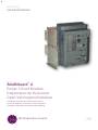
EntelliGuard™ G
Power Circuit Breaker
Disjoncteur de Puissance
Open Vermogenschakelaar
Installation, Operation and Maintenance Manual
Manuel d'installation, d'opération et de maintenance
Installatie-, Gebruikers- en Onderhoudshandleiding
GE imagination at work
English
Français
Nederlands
EntelliGuard G
INTRO
BREAKER
LOCKS
ACCESSORIES
TESTS
APPENDIX
TRIP UNIT
Attention!
Avertissements importants!
OPGELET!
Belangrijke vereisten!
WARNING
Caution!
Important Requirements!
CONTENT
HINTS
WARNING
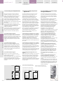
During operation the device described
in this manual is connected to high and
potentially dangerous voltages.
When the circuit breaker is switching
high currents, especially short-circuit
currents, hot and ionized gas may be
emitted.
Only qualified personnel are allowed to
install, commission, maintain or modify
this device in accordance with relevant
safety requirements.
The Circuit Breaker must be equipped
with the appropriate covers and/or be
installed in a suitable enclosure or panel
taking the required safety clearances
into account.
Non Compliance with these
requirements could result in damage to
property and/or severe injury to
personnel.
Read this manual and please retain for
future use.
AVERTISSEMENT
Lors de son fonctionnement, l'appareil
décrit dans ce manuel est connecté à
des courants électriques de haute
tension potentiellement dangereux.
Lorsque le disjoncteur interrompt des
courants élevés, particulièrement des
courants de court-circuit, une émission
de gaz chaud et ionisé peut se produire.
Seul le personnel qualifié est autorisé à
installer, mettre en service, procéder à la
maintenance ou à la modification de cet
appareil conformément aux exigences
de sécurité pertinentes.
Le disjoncteur doit être équipé des
capots appropriés et/ou être installé
dans une armoire ou un tableau qui
respecte les distances de sécurité
indiquées.
Le non-respect de ces conditions peut
causer des dommages matériels et/ou
des blessures graves.
Veuillez lire ce manuel et le conserver pour
son utilisation future.
WAARSCHUWING
Tijdens de bediening is het toestel dat
beschreven wordt in deze handleiding
verbonden met hoge en mogelijk
gevaarlijke voltages.
Wanneer de vermogenschakelaar hoge
stroomsterkten schakelt, voornamelijk
bij kortsluitspanning, wordt er mogelijk
heet en geïoniseerd gas uitgestoten.
Enkel bevoegd personeel mag dit
toestel installeren, in gebruik stellen,
onderhouden of aanpassen in
overeenstemming met de relevante
veiligheidsvereisten.
De Vermogenschakelaar moet uitgerust
worden met de geschikte afdekkappen
en/of geïnstalleerd worden in een
geschikte behuizing of paneel met
respect voor de vereiste vrije ruimte.
Het niet in acht nemen van deze
vereisten leidt mogelijk tot schade aan
eigendommen en/of ernstig letsel bij
personeelsleden.
Lees deze handleiding en bewaar ze voor
later gebruik.
EntelliGuard G
1.0 GENERAL INFORMATION
1.0 INFORMATIONS GÉNÉRALES
1.0 ALGEMENE INFORMATIE
Installation, Operation and Maintenance Manual
Manuel d'installation, d'opération et de
maintenance
Installatie, Gebruikers- en
Onderhoudshandleiding
Disjoncteur de puissance
EntelliGuard™ G
EntelliGuard™ G Open
Vermogenschakelaar
CATÉGORIES DE RISQUES
Les mentions importantes présentées cidessous apparaissent tout au long de ce
document pour avertir le lecteur des risques
potentiels ou pour attirer l'attention sur des
informations qui clarifient une procédure.
Lire attentivement toutes les instructions et se
familiariser avec les appareils avant d'essayer
d'installer, de faire fonctionner ou de procéder à
la maintenance de cet équipement.
RISICOCATEGORIEËN
Volgende informatie vindt u terug doorheen
deze handleiding en waarschuwt voor mogelijke
gevaren of bevat informatie die bepaalde
procedures verduidelijkt.
Lees zorgvuldig alle instructies en maak u
vertrouwd met de toestellen alvorens te trachten
ze te installeren, bedienen, onderhouden of
herstellen.
Indique une situation dangereuse qui, si elle
n'est pas évitée, peut causer la mort ou des
blessures graves.
Duidt een potentieel gevaarlijke situatie aan
die, indien niet vermeden, kan leiden tot
overlijden of een ernstig letsel.
NOTICE: An aid meant to assist the user in
performing the set task. Please retain for future
use.
ATTENTION: le non-respect de ces
instructions peut causer des dommages au
produit.
REMARQUE: un conseil qui vise à aider
l'utilisateur à réaliser la tâche concernée.
Conserver pour toute utilisation future.
LET OP: Het niet in acht nemen van deze
instructies leidt mogelijk tot schade aan het
toestel.
OPMERKING: Er wordt verwacht dat iemand
de gebruiker assisteert bij deze taak. Bewaar
voor later gebruik.
TRADEMARKS
EntelliGuard G
EntelliGuard TU
MARQUES COMMERCIALES
EntelliGuard G
EntelliGuard TU
HANDELSMERKEN
EntelliGuard G™
EntelliGuard TU
WARRANTY
This document is based on information available
at the time of its publication.
While efforts have been made to ensure
accuracy, the information contained herein does
not cover all details or variations in hardware
and software, nor does it provide for every
possible contingency in connection with
installation, operation, and maintenance.
Features may be described herein that are not
present in all hardware and software systems.
GARANTIE
Ce document a été rédigé à partir des
informations disponibles au moment de sa
publication.
Si tous les efforts ont été mis en œuvre pour en
assurer l'exactitude, les informations contenues
ne couvrent toutefois pas l'ensemble des détails
ou variations matérielles et logicielles possibles,
de même qu'elles ne comportent pas toutes les
éventualités liées à l'installation, le
fonctionnement et la maintenance.
Il se peut que des options décrites dans ce
document ne figurent pas dans tous les
systèmes matériels et logiciels.
GE Energy se réserve le droit de modifier ce
document sans en avertir les détenteurs.
GARANTIE
Dit document is gebaseerd op informatie
beschikbaar op het ogenblik van publicatie.
EntelliGuard G Power Circuit Breaker
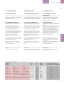
HAZARD CATEGORIES
The following important highlighted information
appears throughout this document to warn of
potential hazards or to call attention to
information that clarifies a procedure.
Carefully read all instructions and become
familiar with the devices before trying to install,
operate, service or maintain this equipment.
1.0
HINTS
INTRO
DANGER | DANGER | GEVAAR
Indicates a hazardous situation which, if not
avoided, could result in death or serious injury.
CAUTION: Failure to comply with these
instructions may result in product damage.
GE Energy assumes no obligation of notice to
holders of this document with respect to
changes subsequently made.
GE Energy makes no representation or warranty,
expressed, implied, or statutory, with respect to,
and assumes no responsibility for the accuracy,
completeness, sufficiency, or usefulness of the
information contained herein.
No warrantees of merchantability or fitness for
purpose shall apply.
Contact your local sales office if further
information is required concerning any aspect of
EntelliGuard G circuit breaker operation or
maintenance.
GE Energy ne fait aucune représentation ou
garantie, explicite, implicite ou statutaire et se
dégage de toute responsabilité concernant
l'exactitude, l'exhaustivité et le caractère
suffisant ou utile des informations contenues
dans ce document.
Aucune garantie n'est accordée concernant la
commercialisation ou la pertinence d'une
utilisation.
En cas de besoin d'informations plus détaillées
sur le fonctionnement ou la maintenance du
disjoncteur Entelliguard G, veuillez contacter
votre bureau de vente local.
Terwijl inspanningen zijn geleverd om
nauwkeurig te zijn, wordt niet gepretendeerd dat
de informatie in deze handleiding alle details of
variaties is hardware of software behandelt, nog
wordt voorzien in elke mogelijke onvoorziene
gebeurtenis met betrekking tot installatie,
werking of onderhoud.
Functies kunnen hierin beschreven worden die
niet aanwezig zijn in alle hardware en software
systemen.
GE Energy is niet verplicht de houders van dit
document in te lichten over wijzigingen die
achteraf zijn aangebracht.
GE Energy biedt geen garantie, uitdrukkelijk,
geïmpliceerd of statutair met betrekking tot, en
aanvaardt geen verantwoordelijkheid voor de
nauwkeurigheid, volledigheid, sufficiëntie of
nuttigheid van de informatie die hierin bevat is.
Er gelden geen garanties van verkoopbaarheid
of geschiktheid voor een bepaald doeleinde.
Neem contact met uw plaatselijk
verkoopkantoor indien verdere informatie vereist
is m.b.t. enig aspect van de bediening of het
onderhoud van de EntelliGuard G
vermogeschakelaar.
1.0-01
EntelliGuard G
INTRO
BREAKER
LOCKS
ACCESSORIES
TESTS
APPENDIX
CONTENT
HINTS
WARNING
TRIP UNIT
1.0-02
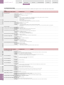
CONTENT
TABLE DES MATIÈRES
INHOUD
1.0 - GENERAL INFORMATION
-------------------------------------------------------1.1.0 Introduction
Quality Assurance
Options Check Sheet
Product Serial & Catalogue Number
Measurement Units
1.0 INFORMATIONS GÉNÉRALES
-------------------------------------------------------1.1.0 Introduction
Assurance qualité
Fiche de récapitulation des options
Numéro de série du produit et numéro de
catalogue
1.0 - ALGEMENE INFORMATIE
-------------------------------------------------------1.1.0 Inleiding
Kwaliteitscontrole
Controlefiche Opties
Serienummer & Catalogusnummer van het
Product Meeteenheden
1.1.1 Short Product Description
1.1.2 Features and Characteristics
1.1.3 Storage
1.1.4 Rating label description
1.1.5 Tools Needed for Installation
1.1.1 Courte description du produit
1.1.2 Fonctions et caractéristiques
1.1.3 Stockage
1.1.4 Description de l'étiquette
1.1.5 Outils nécessaires pour l'installation
1.1.1 Korte beschrijving van het product
1.1.2 Functies en Eigenschappen
1.1.3 Opslag
1.1.4 Beschrijving van het Ratinglabel
1.1.5 Gereedschap nodig bij de Installatie
-------------------------------------------------------1.2 - PRODUCT SPECIFICATIONS
- Tables
-------------------------------------------------------1.3 - INSTALLATION
-------------------------------------------------------1.2 SPÉCIFICATIONS DU PRODUIT
- Tableaux
-------------------------------------------------------1.3 - INSTALLATION
-------------------------------------------------------1.2 - PRODUCTSPECIFICATIES
- Tabellen
-------------------------------------------------------1.3 - INSTALLATIE
1.3.1 Lifting and Mounting
Using Lifting Beams
1.3.2 Fixed-Pattern Circuit Breaker
Installation
1.3.3 Drawout Pattern Circuit Breaker
Installation
Removal from Cassette
Mounting in Cassette
1.3.4 Standard Bus connection
of Fixed AND/OR Drawout pattern.
1.3.5 Secondary Disconnect Terminal Blocks
Location
Use
Table -- General schematics
Table -- Definition of connected devices
to Block A and Block B
1.3.1 Manutention et montage
- Utiliser un chariot de manutention et un adaptateur
1.3.2 Disjoncteur fixe
Installation
1.3.3 Disjoncteur débrochable
Installation
Retrait de la partie fixe
Montage dans la partie fixe
1.3.4 Raccordement standard
des versions fixes et débrochables
1.3.5 Borniers de sectionnement secondaires
Emplacement
Utilisation
Tableau -- Schéma général
Tableau -- Définition des appareils
connectés au bornier A et au bornier B
1.3.1 Optillen en Monteren
Heftruck en Adapter
1.3.2 Vaste Vermogenschakelaar
Installatie
1.3.3 Uitrijdbare Vermogenschakelaar
Installatie
Verwijdering uit de Cassette
Plaatsing in de Cassette
1.3.4 Standaard aansluitwijze
-------------------------------------------------------1.4 - OPERATION
-------------------------------------------------------1.4 - FONCTIONNEMENT
1.3.5 Secundaire Ontkoppeling
Klemmenborden
Locatie
Gebruik
Tabel -- Algemene schema's
Tabel -- Definitie van aangesloten toestellen
naar Blok A en Blok B
-------------------------------------------------------1.4 - BEDIENING
1.4.1 Charging of Main Springs
Manually
Electrically
1.4.1 Armement des ressorts principaux
Manuel
Électrique
1.4.1 Voorspannen van de Veer
Handmatig
Elektrisch
1.4.2 Sequence of breaker operation
1.4.2 Séquence d'opération
1.4.3 Circuit breaker closing operation
1.4.4 Circuit breaker opening operation
1.4.3 Fermeture du disjoncteur
1.4.4 Ouverture du disjoncteur
1.4.2 Sequentie van de werking van de
vermogenschakelaar
1.4.3 Het sluiten van de Vermogenschakelaar
1.4.4 Het openen van de Vermogenschakelaar
1.4.5 Circuit breaker Withdrawal
1.4.6 Circuit breaker Insertion/Cassette
1.4.5 Extraction du disjoncteur
1.4.6 Insertion du disjoncteur
1.4.7 Sequence of operation cassette
1.4.7 Séquence d'opération de la partie fixe
--------------------------------------------------------
--------------------------------------------------------
1.4.5 Verwijderen van de Vermogenschakelaar
1.4.6 Inrijden van de
Vermogenschakelaar/Cassette
1.4.7 Sequentie van de werking van de
cassette
--------------------------------------------------------
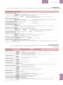
2.0 - TRIP UNIT
General Information
2.1 Product description
2.2 Operation
2.3 LCD Screen Mode
2.4 Time current curves
2.5 Communication Register
2.6 Installation
2.7 Connection scheme
2.8 Troubleshooting
2.9 Catalogue code build
2.0 - UNITÉ DE PROTECTION
Informations générales
2.1 Description du produit
2.2 Opération
2.3 Mode écran LCD
2.4 Courbes
2.5 Registre de communication
2.6 Installation
2.7 Schéma de connexion
2.8 Dépannage
2.9 Structure du code catalogue
2.0 - BEVEILIGINGSUNIT
Algemene informatie
2.1 Productomschrijving
2.2 Bediening
2.3 LCD Schermuitvoering
2.4 Tijd-stroomcurves
2.5 Communicatieregister
2.6 Installatie
2.7 Verbindingsschema
2.8 Probleemoplossing
2.9 Catalogus codestructuur
INTRO
EntelliGuard G
-------------------------------------------------------3.0 - SYSTÈMES DE VERROUILLAGE ET
D'INTERVERROUILLAGE
3.1 Face avant du disjoncteur
- Cadenassage du disjoncteur
- Verrouillage du disjoncteur
- Cadenassage des boutons-poussoirs
--------------------------------------------------------3.0 - SLOTEN EN VERGRENDELINGEN
3.1 Voorzijde Vermogenschakelaar
- Vermogenschakelaarslot
- Sleutelslot Vermogenschakelaar
- Vergrendelen d.m.v. drukknop
3.2 Partie fixe
- Verrouillage des volets de sécurité
- Cadenassage de l'accès à la manivelle de
manœuvre
- Verrouillage des rails
- Interverrouillage de la porte
- Verrous
- Détrompeur de calibre
- Interverrouillage de la porte
3.2.1 Système d'ouverture forcée du volet
3.2.2 Verrouillage des volets
d'isolation de la partie fixe
3.2 Cassette
- Vergrendelen van de Veiligheidssluiting
- Vergrendelen van de rektoegang
- Railsloten
- Deurvergrendeling
- Sleutelsloten
- Misinsertietoestel
- Deurvergrendeling
3.3 Interlocking of Multiple Breakers
- 1 of 2 breaker interlock
- 1 of 3 breaker interlock
- 2 of 3 breaker interlock
- 2 of 3 breaker interlock with priority
3.3 Interverrouillage de plusieurs disjoncteurs
- Interverrouillage d'1 disjoncteur sur 2
- Interverrouillage d'1 disjoncteur sur 3
- Interverrouillage de 2 disjoncteurs sur 3
- Interverrouillage de 2 disjoncteurs sur 3
avec priorité
3.3 Vergrendeling tussen
Vermogenschakelaars
- 1 van 2 Vermogenschakelaarslot
- 1 van 3 Vermogenschakelaarslot
- 2 van 3 Vermogenschakelaarslot
- 2 van 3 Vermogenschakelaarslot met prioriteit
3.4 Network Interlock
3.5 Tables Locking options
-------------------------------------------------------4.0 - ACCESSORIES DESCRIPTION
General Information
3.4 Interverrouillage réseau
3.5 Tableaux des options de verrouillage
-------------------------------------------------------4.0 - DESCRIPTION DES ACCESSOIRES
Informations générales
3.4 Netwerkvergrendeling
3.5 Tabellen Vergrendelingsopties
-------------------------------------------------------4.0 - OMSCHRIJVING VAN DE ACCESSOIRES
Algemene informatie
-------------------------------------------------------3.0 - LOCKS AND INTERLOCKS
3.1 Breaker front Fascia
- Breaker Security Padlocking
- Breaker Security Keylocking
- Pushbutton Padlocking
3.2 Drawout Breaker Cassette
- Shutter Security Padlocking
- Racking handle access Padlocking
- Support Slides Padlocking
- Cassette Security Keylocking
- Standard Drawout Breaker Interlock
- Mis insertion device (Interlock)
- Door interlock
3.2.1 Shutter force open feature
3.2.2 Isolation Shutter Locking
4.1 Releases / Coils
4.2 Electrical Charging Motor
4.3 Contacts
4.4 Installation parts
4.5 Other Accessories
4.6 Spare parts
4.1 Déclencheurs / électros
4.2 Commande électrique
4.3 Contacts
4.4 Accessoires d'installations
4.5 Autres accessoires
4.6 Pièces détachées
CONTENT
1
3.2.1 Forceerfunctie voor openen van de
veiligheidsschermen
3.2.2 Solatiesluitervergrendeling cassette
4.1 Spoelen
4.2 Elektrische Motorbediening
4.3 Contacten
4.4 Installatie-onderdelen
4.5 Accessoires
4.6 Reserve-onderdelen
-------------------------------------------------------5.0 - MAINTENANCE, TESTING AND
TROUBLESHOOTING
-------------------------------------------------------5.0 - MAINTENANCE, TESTS ET DÉPANNAGE
-------------------------------------------------------5.0 - ONDERHOUD, TESTEN EN
PROBLEEMOPLOSSING
5.1 Maintenance
- Inspection Schedule
5.2 Cleaning Procedure
- Arcing Contacts Inspection
- Circuit Breaker Main Mechanism
Inspection
5.3 Cassette Inspection
5.4 Contact wear Inspection
5.5 Isolating Contacts (Drawout Type)
Inspection
5.6 Power Terminals and Busbar Inspection
5.7 Lubrication
5.8 Testing
- Trip Unit Testing
5.9 Troubleshooting
-------------------------------------------------------6.0 - APPENDIX
5.1 Maintenance
- Calendrier d'inspection
5.2 Procédure de nettoyage
- Inspection des pare étincelles
- Inspection du mécanisme principal du
disjoncteur
5.3 Inspection de la partie fixe
5.4 Inspection de l'usure des contacts
5.5 Inspection des contacts d'isolation
(disjoncteur débrochable)
5.6 Inspection des bornes de puissance et des
barres omnibus
5.7 Lubrification
5.8 Tests
- Test de l'unité de protection
5.9 Dépannage
-------------------------------------------------------6.0 - ANNEXE
5.1 Onderhoud
- Inspectieschema
5.2 Reinigingsprocedure
- Inspectie van de Vonkcontacten
- Inspectie van het Hoofdmechanisme van
de Vermogenschakelaar
5.3 Inspectie van de Cassette
5.4 Inspection van Contactslijtage
5.5 Inspectie van de Isolatiecontacten
(Uitrijdbaar type)
5.6 Inspectie van de Stroomklemmenborden en
Busbar
5.7 Smering
5.8 Testen
- Testen van de Beveiligingsunit
5.9 Probleemoplossing
-------------------------------------------------------6.0 - APPENDIX
6.1 Catalogue number description
6.2 Dimension
6.3 Service
6.1 Description du numéro de catalogue
6.2 Dimensions
6.3 Maintenance
6.1 Omschrijving Catalogusnummer
6.2 Afmetingen
6.3 Service
1.0-03
EntelliGuard G
INTRO
BREAKER
LOCKS
ACCESSORIES
TESTS
APPENDIX
Content:
Table des matières:
Inhoud:
1.1.0 Introduction
Quality Assurance
Options Check Sheet
Product Serial Number
Measurement Units
1.1.1 Short Product Description
1.1.2 Features and Characteristics
1.1.3 Storage
1.1.4 Rating label description
1.1.5 Tools Needed for Installation
1.1.0 Introduction
Assurance qualité
Fiche de récapitulation des options
Numéro de série du produit
1.1.0 Inleiding
Kwaliteitscontrole
Controlefiche Opties
Productserienummer
Meeteenheden
1.1.1 Korte beschrijving van het product
1.1.2 Functies en Eigenschappen
1.1.3 Opslag
1.1.4 Beschrijving van het Ratinglabel
1.1.5 Gereedschap nodig bij de Installatie
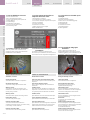
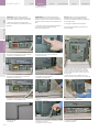
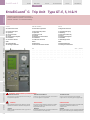
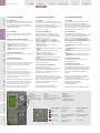
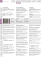
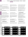
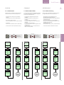
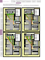
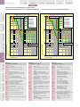
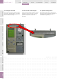
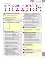
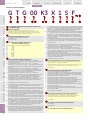
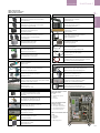
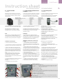
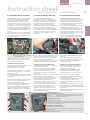
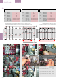
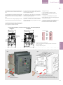
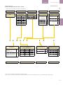
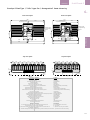
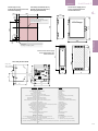
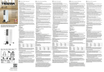
Fig. 1.0: EntelliGuard G Front View
A) Accessory Indicator
B) Charging Handle
C) Electrical ON (Close)
D) Manual ON (Close)
E) Closing Spring Discharge Button
F) ON/OFF Pushbutton Status
G) ON/OFF Status Indicator
H) Spring Charge Status
I) Breaker Rating
J) Ronis/Profalux Key
K) Castell Key
L) Operations Counter
M) Ready to Close Indicator
N) Manual OFF (Open)
O) Breaker Padlock
P) Trip Unit
Q) Manual reset for optional Network Interlock coil
1.1.1 Courte description du produit
1.1.2 Fonctions et caractéristiques
1.1.3 Stockage
1.1.4 Description de l'étiquette
1.1.5 Outils nécessaires pour l'installation
Fig. 1.0: Vue frontale de l'EntelliGuard G
A) Indicateur d'accessoires
B) Levier d'armement
C) ON électrique (fermeture)
D) ON manuel (fermeture)
E) Bouton de décharge des ressorts de fermeture
F) Statut des boutons-poussoirs ON/OFF
G) Indicateur de statut ON/OFF
H) Statut d'armement des ressorts
I) Courant assigné du disjoncteur
J) Verrou Ronis/Profalux
K) Verrou Castell
L) Compteur d'opérations
M) Indicateur « prêt à fermer »
N) OFF manuel (ouverture)
O) Cadenassage du disjoncteur
P) Unité de protection
Q) Acquittement manuel pour l'interverrouillage
réseau optionnel
TRIP UNIT
OPERATION
INSTALLATION SPECIFICATION
INTRO
TRIP UNIT
Q
Afb. 1.0: EntelliGuard G Voorzijde
A) Accessoire-indicator
B) Voorspanhendel
C) Elektrisch AAN (Sluiten)
C) Manueel AAN (Sluiten)
E) Schakelknop Sluitveer
F) Status AAN/UIT-drukknop
G) Statusindicator AAN/UIT
H) Status Laadveer
I) Rating Vermogenschakelaar
J) Ronis/Profalux sleutel
K) Castell sleutel
L) Actieteller
M) Ready to Close-indicator
N) Manueel UIT (Open)
O) Vermogenschakelaarslot
P) Beveiligingsunit
Q) Manuele reset voor de optionele
Netwerkvergrendelingsspoel
A
note
P
O
B
C
E
N
D
.
.
.
.
.
.
.
.
.
.
.
.
.
.
notes | notities
.
.
.
.
.
.
.
.
.
.
.
.
.
.
.
.
.
.
.
.
.
.
.
.
.
.
.
.
.
.
.
.
.
.
.
.
.
.
.
.
.
.
.
.
.
.
.
.
.
.
.
.
.
.
.
.
. . . . . . .
. . . . . . .
. . . . . . .
. . . . . . .
. . . . . . .
. . . . . . .
. . . . . . .
.
.
.
.
.
.
M
G
L
1.1-00
F
K
H
J
I
Global Catalogue Number
Numéro de catalogue globa
Algemeen artikelnummer
Serial Number
Numéro de série
Serienummer
BREAKER
EntelliGuard G
1.1 INTRODUCTION
1.1 INLEIDING
Quality Assurance
All EntelliGuard G circuit breakers have been
designed and manufactured to the highest
technical standards.
GE uses strict procedures ensuring that the
mentioned technical standards are met whilst
maintaining a first class product quality.
Assurance qualité
Tous les disjoncteurs Entelliguard G ont été
conçus et fabriqués selon les critères techniques
les plus exigeants.
GE suit des procédures strictes qui garantissent
le respect de ces critères techniques ainsi qu'une
qualité de tout premier ordre.
Kwaliteitscontrole
Alle EntelliGuard G Vermogenschakelaars zijn
ontwikkeld en geproduceerd volgens de hoogste
technische normen.
GE maakt gebruik van strenge procedures om te
verzekeren dat deze technische normen
gehandhaafd worden met behoud van een
superieure productkwaliteit.
Options Check Sheet
Each circuit breaker comes with an options
check sheet that lists all optional features and
accessories included in the circuit breaker,
cassette and trip unit (if ordered)
Fiche de récapitulation des options
Chaque disjoncteur est fourni avec une fiche de
récapitulation des options qui détaille toutes les
options et tous les accessoires commandés avec
le disjoncteur, la partie fixe et l'unité de
protection (selon commande).
Description du numéro de catalogue
voir Annexe
1.1
INTRO
1.1 INTRODUCTION
Catalogue number description
see Appendix
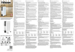
Product Serial & Catalogue Number
When communicating with GE on any aspect of
this device please mention the serial number &
the global catalogue number.
The serial number is unique for each device,
whilst the catalogue number provides all
technical and configuration data.
These codes can be found on the front labels of
the device as indicated on page 1.1-00 .
Numéro de série du produit et numéro de
catalogue
Veuillez mentionner le numéro de série et le
numéro de catalogue de cet appareil dans toute
communication avec GE. Le numéro de série est
unique pour chaque appareil, et le numéro de
catalogue fournit des informations techniques et
relatives à la configuration.
Ces codes se trouvent sur les étiquettes de la
face avant de l'appareil, comme indiqué en page
1.1-00.
1.1.1 Short Product description
1.1.1 Courte description du produit
The EntelliGuard G Power Circuit breaker is an Air
Circuit Breaker designed to meet the Global
ANSI, UL and IEC standards. This manual being
specifically dedicated to the design meeting the
IEC/EN 60947 standard, for other standards
please contact us.
Le disjoncteur de puissance Entelliguard G est
conçu pour être conformes aux normes Global
ANSI, UL et CEI. Ce manuel concerne
spécifiquement la version conçue pour la norme
CEI/EN 60947. Pour les autres normes, veuillez
nous contacter.
The device is designed for use in networks with
voltages up to 1000V AC or 750V DC and to be
fully selective with other EntelliGuard and GE
Record Plus Circuit Breakers.
Cet appareil est conçu pour fonctionner dans
des réseaux dont la tension peut aller jusqu'à
1000 V ca. ou 750 Vcc. et pour assurer une
pleine sélectivité avec les autres disjoncteurs
EntelliGuard et GE Record Plus.
It is available as 3 or 4 pole device in three
envelopes and can be used for current ratings
from 80 up to 6400 Amps.
As a breaker the EntelliGuard G can be equipped
with one of four Electronic Trip Unit types each
having the same universal setting interface and
an LCD screen.
A Non Automatic (Switch Disconnector) version
(without trip unit) is also possible. Both Breaker
and Switch Disconnector types are available in a
Fixed or Drawout pattern.
EntelliGuard G devices offer a combination of
high interruption and short time current
withstand ratings and can be used in
applications as Mains, Coupler/Tie or feeder
breaker or switch disconnector.
Il est disponible en version 3 ou 4 pôles, en trois
tailles, et peut être utilisé avec des courants
nominaux de 80 à 6400 A.
Le disjoncteur EntelliGuard G peut être équipé
d'une des quatre unités de protection
électronique, qui sont toutes équipées de la
même interface de réglage universelle et d'un
écran LCD.
Une version interrupteur (sans unité de
protection) est également disponible. Le
disjoncteur et l'interrupteur sont disponibles en
version fixe ou débrochable.
Les appareils Entelliguard offrent une
combinaison de pouvoir de coupure et de
courant de courte durée admissible élevés, et
peuvent être utilisés comme disjoncteurs de
réseau, de coupleur ou de ligne ou comme
interrupteur.
Controlefiche Opties
Elke vermogenschakelaar wordt geleverd met
een Controlefiche voor de opties met een
overzicht van alle optionele functies en
accessoires van de vermogenschakelaar,
cassette en beveiligingsunit (indien aangekocht).
Omschrijving Catalogusnummer
Raadpleeg de Appendix
Serienummer & Catalogusnummer van het
Product
Bij elke communicatie met GE m.b.t. enig aspect
van dit toestel, vermeld svp het serienummer &
het algemene catalogusnummer.
Het serienummer is uniek voor elk toestel, terwijl
het catalogusnummer alle technische gegevens
en configuratiegegevens bevat. Deze codes
vindt u op de labels aan de voorzijde van het
toestel, zoals weergegeven op pagina 1.1-00.
1.1.1 Korte beschrijving van het
Product
De EntelliGuard G Vermogenschakelaar is een
Open Vermogenschakelaar ontwikkeld volgens
de Globale ANSI, UL en IEC normen. Deze
handleiding is specifiek ontwikkeld voor het
productdesign dat overeenstemt met de IEC/EN
60947 -norm, voor de andere normen, neem
met ons contact op.
Het toestel is ontworpen voor gebruik in
netwerken met voltages tot 1000V AC of 750V
DC en kan gebruikt worden met andere
EntelliGuard en GE Record Plus
vermogenschakelaars.
Het toestel is beschikbaar als 3- of 4-polig
toestel in drie bouwgroottes en kan gebruikt
worden voor stroomsterkten van 80 tot 6400
Ampère.
Als vermogenschakelaar kan de EntelliGuard G
uitgerust worden met een van de vier
Elektronische Beveiligingsunits die allen
beschikken over dezelfde universele
instellingeninterface en LCD-schermen.
Een niet-automatische (Schakelaarbediende)
versie (zonder beveiligingsunit) is ook
beschikbaar. Zowel de Vermogenschakelaar- als
de Schakelaarbediende types zijn beschikbaar in
een vaste en uitrijdbare uitvoering.
EntelliGuard-toestellen bieden een combinatie
van hoge interruptie en
korteddurstroomweerstandwaarden en kunnen
gebruikt worden bij toepassingen als
Hoofdschakelaar, Koppelschakelaar of
Voedingschakelaar of Schakelaarbediend
toestel.
1.1-01
EntelliGuard G
INTRO
BREAKER
LOCKS
ACCESSORIES
TESTS
APPENDIX
TRIP UNIT
OPERATION
INSTALLATION SPECIFICATION
INTRO
TRIP UNIT
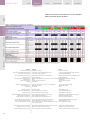
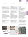
1.1.2 Features and Characteristics
1.1.2 Fonctions et caractéristiques
1.1.2 Functies en Eigenschappen
Standard and Optional Features
Fonctions standard et optionnelles
Standaard en Optionele Functies
Rated Short Time Withstand Current::
Up to 100kA for 1 sec
Courant assigné de courte durée admissible:
Jusqu'à 100 kA pour 1 sec.
Korteduurstroom:
Tot 100kA gedurende 1 sec.
Short Circuit / Interruption Rating:
(Breaking Capacity)
Up to 150kA at 440V & 100kA at 690V
Pouvoir de coupure:
jusqu'à 150 kA à 440 V et 100 kA à 690 V
Kortsluiting / Interruptierating:
(Schakelcapaciteit)
Tot 150kA bij 440V & 100kA bij 690V
Rated Current:
The devices have a 100% normal current rating
up to an ambient temperature of 50°C in free air.
Connection of Power supply
EntelliGuard G devices can be fed from top or
bottom terminals.
Stored Energy Mechanism:
An EntelliGuard G circuit breaker uses a stored
energy mechanism that can be charged
manually or electrically. For manual charging
the operating handle is used ,a spring charging
motor supplied with an indication contact can
be added for electrical charging. Device closing
time is less than five half cycles.
Closing and opening can be initiated remotely or
via the front cover push buttons. An O-C-O cycle
is possible without recharging. The breaker
operating mechanism is trip-free and has an
integrated anti-pumping system.
Factory fitted -ORField installable Accessories & Trip Units.
Accessories common to all breaker envelopes
are available in two different versions.
-- 1. Factory Mounted units
-- 2. Field installable Units supplies with all
necessary connection & Fixation hardware.
Coils:
EntelliGuard G devices have provisions for a
maximum of 4 coils.
Combinations of two shunt releases (ST), two
undervoltage releases (UVR), one closing coil or
one command closing coil are possible (see table
chapter 4). The shunt releases (ST) are
continuous rated. Undervoltage releases have a
built in time delay of up to 50 ms, an external
time delay module is available if longer time
delays are required (TDM). Both closing coils are
equipped with an anti-pumping mechanism.
Optional status indication contacts are available
for the ST, CC and UVR-coils. They can be wired
out through the trip unit communication option
and/or through the secondary disconnects.
Network Interlock:
Replacing one Shunt release (ST) and one
Undervoltage release (UVR) this optional device
locks out the breaker electrically and
mechanically.
Breaker / Main Contact Status:
OPEN/CLOSED, ON/OFF indication is provided on
the front cover.
Motor Operator:
Motor/gearbox unit; easily accessible.
1.1-02
Courant nominal:
Les appareils ont un courant nominal sans
déclassement dans une température ambiante
jusqu'à 50°C à l'air libre.
Raccordement de l'alimentation
Les appareils EntelliGuard G peuvent être
indifférement alimentés par des bornes
supérieures et inférieures.
Mécanisme à accumulation d'énergie:
Le disjoncteur EntelliGuard G fonctionne grâce à
un mécanisme à accumulation d'énergie à
armement manuel ou électrique. L'armement
manuel se fait à l'aide d'un levier, et une
commande électrique fournie avec un contact
d'indication peut être ajoutée pour l'armement
électrique. Le temps de fermeture de l'appareil
est inférieur à cinq demi-cycles.
La fermeture et l'ouverture peuvent être
déclenchées à distance ou via les boutonspoussoirs de la face avant. Un cycle ouverturefermeture-ouverture est possible sans
réarmement. Le mécanisme du disjoncteur est
anti-forçage et est équipé d'un système antipompage intégré.
Accessoires et unités de protection montés en
usine OU montables sur site
Les accessoires communs à toutes les tailles de
disjoncteur sont disponibles en deux versions.
-- 1. Montés en usine
-- 2. Montables sur site, livrés avec tout le
matériel nécessaire de raccordement et de
fixation.
Électros:
Les appareils EntelliGuard G peuvent être
équipés d'un maximum de 4 électros.
Des combinaisons de deux déclencheurs à
émission de courant, deux déclencheurs à
manque de tension, un électro d'enclenchement
et un électro d'enclenchement de commande
sont possibles (voir le tableau du chapitre 4). Les
déclencheurs à émission de courant sont à
courant permanent. Les déclencheurs à
manque de tension sont dotés d'une
temporisation intégrée de jusqu'à 50 ms. Un
module de temporisation externe est disponible
pour des temporisations plus longues. Les deux
type d'électros d'enclenchement sont équipés
d'un mécanisme anti-pompage.
Des contacts d'indication d'état sont disponibles
en option pour les déclencheurs à émission de
courant et à manque de tension ainsi que pour
les électros d'enclenchement. Ils peuvent être
raccordés via l'option de communication de
l'unité de protection et/ou via les connecteurs
externes.
Interverrouillage réseau:
Ce dispositif optionnel remplace un déclencheur
à émission de courant et un déclencheur à
manque de tension, et verrouille le disjoncteur
électriquement et manuellement.
Contact d'indication de position:
Indication d'état OUVERT/FERMÉ, ON/OFF sur la
face avant.
Commande électrique:
Unité moteur/transmission facile d'accès.
Nominale spanning:
De toestellen hebben een 100% nominale
spanningsrating tot een omgevingstemperatuur
van 50°C in open lucht.
Aansluiting van de Stroomtoevoer
EntelliGuard G-toestellen kunnen gevoed
worden vanuit boven- of onderklemmenborden.
Energieopslagmechanisme:
Een EntelliGuard G vermogenschakelaar
gebruikt een energieopslagmechanisme dat
manueel of elektrisch gespannen kan worden.
Voor het manueel laden wordt de
bedieninghendel gebruikt, en er kan een
veerspanningsmotor met indicatiecontact
toegevoegd worden voor elektrisch laden.
Sluitreactie van het toestel is minder dan vijf
halve cycli.
Sluiten en openen kan gebeuren vanop afstand
of via de drukknoppen op de voorzijde. Een O-GO-cyclus is mogelijk zonder herladen. Het
mechanisme van de vermogenschakelaar is van
het vrije schakeltype en beschikt over een
geïntegreerd anti-pompsysteem.
Voorgemonteerde -OF- Zelf te installeren
Accessoires & Beveiligingsunits.
Accessoires die gebruikt kunnen worden voor
alle bouwgrootten zijn beschikbaar in twee
verschillende versies.
-- 1. Voorgemonteerde units
-- 2. Zelf te installeren units geleverd met alle
benodigde aansluitingen & montagehardware.
Spoelen:
EntelliGuard G -toestellen zijn voorzien voor
gebruik van maximaal 4 spoelen.
Combinaties van twee uitschakelspoelen (ST),
twee onderspanningsspoelen (UVR), één
inschakelspoel of één commandoinschakelspoel zijn mogelijk (raadpleeg tabel
hoofdstuk 4). De uitschakelspoelen (ST) zijn
continu nominaal. Onderspanningsspoelen
hebben een ingebouwde tijdvertraging tot 50ms,
een externe tijdvertragingsmodule is
beschikbaar indien langere tijdvertragingen
vereist zijn (TDM). Beide inschakelspoelen zijn
uitgerust met een anti-pompmechanisme.
Optionele statusindicatiecontacten zijn
beschikbaar voor de ST, CC en UVR-spoelen. Ze
kunnen aangesloten worden via de
communicatieoptie van de beveiligingsunit en/of
via de secundaire uitschakelpatronen.
Netwerkvergrendeling:
Door het vervangen van één uitschakelspoel (ST)
en één onderspanningsspoel (UVR) wordt de
vermogenschakelaar elektrisch en mechanisch
vergrendeld.
Vermogenschakelaar / Hoofdcontactstatus
OPEN/GESLOTEN, AAN/UIT indicator bevindt zich
op de voorzijde.
Motorbediening:
Motor/transmissie-unit; eenvoudige toegang.
BREAKER
EntelliGuard G
Electrical Closing Button:
Located on the front cover; electrically closes
breaker.
Bouton de fermeture électrique:
Situé sur la face avant, il permet la fermeture
électrique du disjoncteur.
Elektrische Inschakelknop:
Bevindt zich op de voorzijde, sluit de
vermogenschakelaar elektrisch.
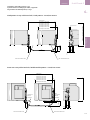
Mounting Brackets
Kits are available to facilitate wall mounting of
an Entelliguard Envelope 1 or 2 Fixed pattern
device. These are recommended for use when a
Power Circuit breaker is equipped with Front
access Connection terminals.
Brides de montage
Des kits sont disponibles pour faciliter le
montage mural des tailles 1 ou 2 des
disjoncteurs EntelliGuard de type fixe. Ils sont
recommandés lorsqu'un disjoncteur de
puissance est équipé de prises avant.
Connection modes
Connection sets are available to adapt the
standard connection mode (Rear Horizontal) of
the fixed pattern breaker to a front or Vertical
rear connection mode.
The cassettes for the devices in drawout mode
are supplies with universal connectors for rear
horizontal or vertical use or front connection
pads. Sets with these connectors are available
as spare parts.
Modes de connexion
Des kits de connexion sont disponibles pour
changer le mode de connexion standard (prises
arrières horizontales) du disjoncteur fixe en
prises avant ou arrières verticales.
Les parties fixes des appareils débrochables
sont livrées avec prises arrières universelles
(horizontales et verticales) ou avec des prises
avant. Les kits contenant ces connecteurs sont
disponibles en pièces détachées.
Montagebeugels
Er zijn kits beschikbaar voor een eenvoudige
muurmontage van een EntelliGuard
bouwgrootte 1 of 2 toestel met vaste uitvoering.
Deze worden aanbevolen wanneer een
vermogenschakelaar uitgerust is met
aansluitklemmenborden met opening aan de
voorzijde.
Auxiliary Contacts
4 available designs:
-- Power rated 3NO & 3NC (default)
-- Power rated, 8NO & 8NC
-- Power rated, 3NO & 3NC + signal rated 2NO &
2NC
-- Power rated, 4NO & 4NC + signal rated 4NO &
4NC
Contacts auxiliaires
4 versions disponibles:
-- Contacts de puissance 3 NO et 3 NF (défaut)
-- Contacts de puissance 8 NO et 8 NF
-- Contacts de puissance 3 NO et 3 NF +
contacts de signal 2 NO et 2 NF
-- Contacts de puissance 4 NO et 4 NF +
contacts de signal 4 NO et 4 NF
Interlocks
Standard Interlocking Feature
Drawout Breaker
The cassettes and device mobile part are
equipped with a interlock that prevents the
breaker from closing unless it is in the TEST or
CONNECTED position.
When the main breaker contacts are closed a
second interlock prevents insertion of the
devices racking handle into the aperture on the
cassette.
Interverrouillage
Fonction d'interverrouillage standard
Disjoncteur débrochable
La partie fixe et la partie mobile de l'appareil
sont équipées d'un système d'interverrouillage
qui empêche la fermeture du disjoncteur à
moins qu'il ne soit en position TEST ou INSÉRÉ.
Lorsque les contacts du disjoncteur principal
sont fermés, un deuxième système
d'interverrouillage empêche l'insertion de la
manivelle de manœuvre dans la partie fixe.
Breaker Status Indicators:
Standard Indicators include:
-- The breaker status indicator shows the
condition of the main contacts (OPEN, CLOSED).
-- The status of the closing springs is indicated
as CHARGED or DISCHARGED.
-- Ready to Close Indicator provides visible
indication/readiness for close operation.
-- The draw-out position indicator displays
whether the breaker is in the CONNECT, TEST or
DISCONNECT position.
-- The breaker also includes a switch that
provides main contact status indication.
Indicateurs de statut du disjoncteur:
Les indicateurs standard comprennent:
-- L'indicateur de statut du disjoncteur qui
montre l'état des contacts principaux (FERMÉ,
OUVERT).
-- Le statut des ressorts de fermeture est
indiqué comme ARMÉ ou DÉSARMÉ.
-- L'indicateur « prêt à fermer » donne une
indication visible lorsque l'appareil est prêt à être
fermé.
-- L'indicateur de position de la partie mobile
montre la position du disjoncteur, INSÉRÉ, TEST
OU DÉBROCHÉ.
-- Le disjoncteur comprend également un
commutateur qui indique le statut du contact
principal.
Mis insertion Feature
An optional mis insertion feature prevents
mismatching breakers and cassettes /
substructures.
This prevents
a) inserting a breaker with a lower rating
into a higher rated cassette/substructure
and
b) inserting a higher rated breaker into a
lower rated cassette/substructure.
Through-door Racking:
The breaker racking mechanism is accessible
through the front door and permits safely
disconnecting/withdrawing the circuit breaker
Fonction de détrompage de calibre
Une fonction optionnelle de détrompage de
calibre empêche les erreurs de configuration
entre parties mobiles et partie fixes.
Cela évite d'insérer un disjoncteur de calibre
inférieur ou supérieur dans une partie fixe/
Manœuvre à travers la porte:
Le mécanisme de manœuvre du disjoncteur est
accessible à travers la porte avant et permet de
déconnecter/désengager le disjoncteur sans
ouvrir la porte niexposer le personnel aux
parties actives pendant la manoeuvre.
INTRO
1.1
Aansluitingen
Er zijn aansluitsets beschikbaar om de
standaard aanluituitvoering (achterzijde
horizontaal) van de vermogenschakelaar met
vaste uitvoering aan te passen naar een
uitvoering voor aansluiting aan de voorzijde of
achterzijde verticaal.
De cassettes voor de toestellen in uitrijdbare
uitvoering worden geleverd met universele
connectors voor horizontaal of verticaal gebruik
aan de achterzijde of met de connectieklemmen
voor de voorzijde. Deze connectorsets zijn
beschikbaar als reserveonderdelen.
Hulpcontacten
4 beschikbare designs:
-- Vermogen nominaal 3NO & 3NC (standaard)
-- Vermogen nominaal 8NO & 8NC
-- Vermogen nominaal, 3NO & 3NC + signaalgestuurd 2NO & 2NC
-- Vermogen nominaal, 4NO & 4NC + signaalgestuurd 4NO & 4NC
Vergrendelingen
Standaard Vergrendelingsfunctie
Uitrijdbare Vermogenschakelaar
De cassettes en mobiele onderdelen van het
toestel zijn uitgerust met een vergrendeling die
het sluiten van de vermogenschakelaar
verhindert tenzij deze zich in de positie TEST of
INGEREDEN bevindt.
Wanneer de contacten van de hoofdschakelaar
gesloten zijn, verhindert een tweede
vergrendeling dat de uitrijdhendel van het
toestel in de opening van de cassette kan
geplaatst worden.
Statusindicators van de Vermogenschakelaar:
Standaardindicators zijn:
-- De statusindicator van de
vermogenschakelaar toont de toestand van de
hoofdcontacten (OPEN, GESLOTEN).
-- De status van de veer wordt weergegeven als
GESPANNEN of NIET-GESPANNEN.
-- Ready to Close-indicator biedt een visuele
indicatie/gereedheid voor de sluitfunctie.
-- De uitrijdpositie-indicator duidt aan of de
vermogenschakelaar zich in de INGEREDEN,
TEST of UITGEREDEN positie bevindt.
-- De vermogenschakelaar bevat ook een
schakelaar die een statusindicatie geeft van het
hoofdcontact.
Misinsertiefunctie
Een optionele misinsertiefunctie verhindert het
plaatsen van niet-overeenstemmende
vermogenschakelaars en cassettes /
substructuren.
Hierdoor wordt verhinderd dat
a) er een vermogenschakelaar met een lagere
rating verbonden wordt met een cassette /
1.1-03
EntelliGuard G
INTRO
BREAKER
LOCKS
ACCESSORIES
TESTS
APPENDIX
TRIP UNIT
TRIP UNIT
OPERATION
INSTALLATION SPECIFICATION
INTRO
without opening the door and exposing
personnel to live parts during the process.
1.1-04
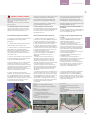
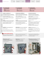
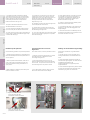
Padlocking devices:
EntelliGuard G Power Circuit Breakers are
supplied with several padlocking devices. The
breaker in fixed and draw-out pattern have a
padlocking facility for one padlock of 5-8 mm
allowing the breaker to be locked in its OFF
position.
The cassette supplied with the breakers in drawout mode has three facilities for up to 3 padlocks
of 5-8 mm.
Two of these can be found on the cassette
euchenon and can be used for locking the
shutters in closed position and/or closing and
locking the racking handle aperture.
The third option is located on the breaker drawout support slides and can be used to lock
breaker & chassis combination in disconnected
position.
Systèmes de cadenassage:
Les disjoncteurs de puissance EntelliGuard G
sont fournis avec plusieurs dispositifs de
cadenassage. Les disjoncteurs fixes et
débrochables sont équipés d'un système de
cadenassage pour un cadenas de 5-8 mm qui
permet de verrouiller le disjoncteur en position
OFF.
La partie fixe fournie avec les disjoncteurs
débrochables peut être équipée de maximum 3
cadenas de 5-8 mm.
Deux d'entre eux se trouvent sur la face avant
de la partie fixe et peuvent être utilisés pour
verrouiller les volets d'isolement en position
fermée et verrouiller le logement de la manivelle
de manœuvre.
La troisième option se trouve sur les rails du
support du disjoncteur débrochable et peut être
utilisée pour verrouiller l'ensemble disjoncteur et
châssis en position DÉBROCHÉ.
Facia Pushbutton Padlocking Facilities:
To prevent un-authorized access to both the ON
and OFF push buttons on the breakers front
facia, a padlock able push button cover can be
fixed to the breaker front facia.
1 padlock of 5-8 mm can be used.
Emplacement de cadenassage des boutonspoussoirs sur la face avant:
Un capot de bouton-poussoir cadenassable
peut être fixé sur la face avant du disjoncteur
pour empêcher tout accès non autorisé aux
boutons-poussoirs ON et OFF.
1 cadenas de 5-8 mm peut être utilisé.
Key Locking mechanism
Multiple kits are available allowing the use of
Ronis, Profalux or Castell Key locks. Both the
breaker and cassette can be equipped with
these facilities. The breaker can accept
mechanisms allowing the use of up to four Ronis
or Profalux locks or one Castell lock that allow
one to lock the device in OFF position.
The cassette only accepts mechanisms allowing
the use of Ronis and/or Profalux locks that can
be used for breaker position and/or shutter
locking.
Mécanisme de verrouillage à clé
Plusieurs kits sont disponibles pour utiliser des
verrous Ronis, Profalux ou Castell. Ces
mécanismes peuvent être montés sur le
disjoncteur et sur la partie fixe. Le disjoncteur
accepte des mécanismes pour maximum quatre
verrous Ronis ou Profalux, ou un verrou Castell
qui permet de verrouiller l'appareil en position
OFF.
La partie fixe accepte des mécanismes
permettant d'utiliser des verrous Ronis et/ou
Profalux pour verrouiller la position du
disjoncteur et/ou des volets de sécurité.
Shutters:
All cassettes are supplied with lockable safety
shutters.
Volets:
Toutes les parties fixes sont équipées de volets
de sécurité verrouillables.
Cassette Position Indication Contacts:
This optional cassette/substructure device
permits local or remote indication of the circuit
breaker status(CONNECTED, TEST,
DISCONNECTED. (Set of 3 or 6 single-pole
changeover contacts are available).
Contacts d'indication de position de la partie
fixe:
Ce dispositif optionnel pour la partie fixe permet
d'indiquer localement ou à distance le statut du
disjoncteur (INSÉRÉ, TEST, DÉBROCHÉ). Des jeux
de contacts inverseurs de signalisation 3 ou 6
pôles sont disponibles.
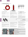
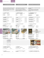
Lifting Truck and Adapter:
Optionally available to facilitate breakers
handling. The standard type is suitable for
handling Envelope 1 & 2 breakers, an adapter
being available allowing one to use the same
device for envelope 3 devices.
Chariot de manutention et adaptateur:
Disponibles en option pour faciliter la
manutention des disjoncteurs. Le type standard
convient à la manutention des disjoncteurs de
taille 1 et 2, et un adaptateur est disponible pour
utiliser le même appareil avec les disjoncteurs
de taille 3.
IP54 Covers:
Each EntelliGuard breaker is supplied with a
Door Frame that provides the installed device
with an IP40 rating. Optionally an extra cover is
available providing an IP54 rating.
Capots IP54:
Chaque disjoncteur EntelliGuard est livré avec un
cadre de porte qui donne à l'appareil installé un
degré de protection IP40. Un capot
supplémentaire est disponible en option pour
atteindre un degré de protection IP54.
substructuur met een hogere rating en
b) er een vermogenschakelaar met een hogere
rating verbonden wordt met een cassette /
substructuur met een lagere rating.
Uitrijdmechanisme door de deur:
Het rekschakelingmechanisme van de
vermogenschakelaar is toegankelijk via de deur
aan de voorzijde en zorgt voor een veilige
ontkoppeling/verwijdering van de
vermogenschakelaar zonder de deur te openen
en personeel bloot te stellen aan onderdelen
onder spanning gedurende het proces.
Sloten:
EntelliGuard G™ vermogenschakelaars worden
geleverd met twee standaard
hangslottoestellen. De vermogenschakelaar in
Vaste- en uitrijdbare uitvoering hebben een
hangslotfacilitiet voor een hangslot van 5-8 mm
om de schakelaar in de UIT-positie te
vergrendelen.
De cassette die geleverd wordt bij de
schakelaars in uitrijdbare uitvoering hebben drie
faciliteiten voor maximaal 3 hangsloten van 5-8
mm.
Twee ervan vindt u op de cassetterozet en
kunnen gebruikt worden voor vergrendeling van
de afsluiters in gesloten positie of voor sluiting
en vergrendeling van de
montagehendeluitsparing.
De derde optie bevindt zich op de steunrails van
de schakelaar en kunnen gebruikt worden om
de schakelaar & chassiscombinatie in de
ontkoppelde positie te vergrendelen.
Drukknopvergrendeling op voorzijde:
Ter preventie van ongeoorloofde toegang tot
zowel de AAN- als UIT-drukknoppen op de
voorzijden van de schakelaars, is er een
vergrendelbare voorzijde beschikbaar.
Gebruik 1 hangslot van 5-8 mm.
Sleutelslotmechanisme
Er zijn meerdere kits beschikbaar die het gebruik
toelaten van Ronis, Profalux of Castell
sleutelsloten. Zowel de vermogenschakelaar als
de cassette kunnen hiermee worden uitgerust.
Bij de vermogenschakelaar kunnen tot
maximaal vier Ronis of Profalux sloten of één
Castell slot gebruikt worden waardoor het
toestel in de UIT-positie kan vergrendeld worden.
Bij de cassette kunnen alleen Ronis en/of
Profalux sloten gebruikt worden om de
vermogenschakelaarpositie en/of sluiter te
vergrendelen.
Sluiters:
Alle cassettes worden geleverd met
vergrendelbre veiligheidssluiters.
Positieindicatiecontacten Cassette:
Met dit optioneel cassette/substructuur -toestel
kunt u ter plaatse of vanop afstand de status
van de vermogenschakelaar raadplegen
(INGEREDEN, TEST, UITGEREDEN). (Set van 3 of 6
enkelpolige wisselcontacten zijn beschikbaar).
Heftruck en Adapter:
Optioneel beschikbaar voor het manipuleren van
de vermogenschakelaar. Het standaardtype is
geschikt voor Bouwgrootte 1 & 2, er is een
adapter beschikbaar om hetzelfde toestel te
gebruiken voor Bouwgrootte 3.
BREAKER
EntelliGuard G
Operations Counter:
Provides local record of the cumulative number
of complete breaker closing operations.
Compteur d'opérations:
Enregistre localement le nombre d'opérations de
fermeture du disjoncteur.
Cable Interlocking Devices:
A set of devices that are available for fixed
and/or drawout devices. They allow the
interlocking of two or three Entelliguard G
breakers in fixed or drawout pattern. Each
device has two parts, a factory mounted
interlocking mechanisms and two or more
separately available cables.
Systèmes d'interverrouillage par câbles:
Ces systèmes sont disponibles pour les appareils
fixes et/ou débrochables. Ils permettent
d'interverrouiller deux ou trois disjoncteurs
EntelliGuard G fixes ou débrochables. Chaque
système est composé de deux parties, un
mécanisme d'interverrouillage monté en usine et
deux ou plusieurs câbles disponibles
séparément.
Bell Alarm Contact:
A changeover contact that once fitted to the
breaker indicates if the breakers has tripped on
one of it's protective functions (Electronic Trip
Unit).
An interface on the Trip Unit front face allows a
Manual or Automatic breakers reset. The Bell
Alarm Contact will only permanently change
position when the Trip Unit is in Manual mode.
The Trip unit has a function (trip reason and
event logger ) that allows the user to establish
why the breaker has tripped.
Contact de signalisation de défaut:
Ce contact inverseur de signalisation, une fois
monté sur le disjoncteur, indique si le disjoncteur
s'est déclenché sur l'une de ses fonctions de
protection (unité de protection électronique).
Une interface placée sur la face avant de l'unité
de protection permet un acquittement manuel
ou automatique des disjoncteurs. Le contact de
signalisation de défaut ne change de position de
façon permanente que lorsque l'unité de
protection est en mode manuel.
La fonction d'indication de la raison du
déclenchement et de journal d'événement de
l'unité de protection permet à l'utilisateur de
déterminer la raison pour laquelle le disjoncteur
s'est déclenché.
Spring Charged and Ready to Close Contacts:
A breaker with electrical charging mechanism
can be equipped with one or two indication
contacts.
Contacts « ressort armé » et « prêt à fermer »
Les disjoncteurs équipés d'une commande
électrique peuvent être équipés d'un ou deux
contacts d'indication en option.
The first the Spring Charged Contact simply does
as indicated and is supplied with the standard
Motor Operating Mechanism.
Le premier contact « ressort armé » agit
simplement comme indiqué et est fourni avec la
commande électrique standard.
The second, the ready to close indication,
optionally replaces the Spring Charged Contact.
Le deuxième contact « prêt à fermer » peut
optionnellement remplacer le contact « ressort
armé ».
Il ne change de position que lorsque les
conditions suivantes sont satisfaites:
- le disjoncteur est ouvert
- les ressorts de fermeture sont armés
- le disjoncteur n'est pas verrouillé/interverrouillé
en position ouverte
- il n'y a pas de commande permanente de
fermeture
- il n'y a pas de commande permanente
d'ouverture.
Les deux contacts sont disponibles dans une
configuration 1 NO.
It only moves position when the following
conditions are met:
- The circuit breaker is open
- The closing springs are charged
- The circuit breaker is not locked/interlocked in
open position
- There is no standing closing order
- There is no standing opening order
Both contacts have a 1NO configuration.
1.1.3 Storage
1.1.3 Stockage
Store circuit breakers and cassettes in a clean,
dry location in their original packaging.
Les disjoncteurs et les parties fixes doivent être
stockés dans un endroit propre et sec, dans leur
emballage d'origine.
IP54 Covers:
Elke EntelliGuard vermogenschakelaar wordt
geleverd met een deurframe wat het
geïnstalleerde toestel voorziet van een IP40rating. Er is een optionele extra cover
beschikbaar voor een IP54-rating.
INTRO
1.1
Actieteller:
Biedt een plaatselijke registratie van het
cumulatieve aantal acties van een volledige
sluiting van de vermogenschakelaar.
Kabelslottoestellen:
Een set toestellen die beschikbaar zijn voor de
vaste en uitrijdbare uitvoeringen. Ze zijn bedoeld
om twee of drie vaste of uitrijdbare EntelliGuard
G vermogenschakelaars te vergrendelen. Elk
toestel heeft twee onderdelen, een
voorgemonteerd vergrendelingsmechanisme en
twee of meer afzonderlijk verkrijgbare kabels.
Belalarmcontacten:
Een wisselcontact dat, eens op de
vermogenschakelaar gemonteerd, aangeeft of
de vermogenschakelaar uitgeschakeld is door
één van de beveiligingsfuncties (Elektronische
Beveiligingsunit).
Met een interface op de voorzijde van de
Beveiligingsunit kan de vermogenschakelaar
manueel of automatisch worden gereset. Het
Bellalarmcontact zal enkel permanent van
positie wijzigen wanneer de Beveiligingsunit in
de Manuele uitvoering geschakeld is.
De Beveiligingsunit bezit een functie
(uitschakelreden en gebeurtenissenlogboek)
waarmee de gebruiker kan ontdekken waarom
de vermogenschakelaar gereageerd heeft.
'Veer Gespannen' en 'Ready to Close' (Gereed
om te Sluiten)-contacten:
Een schakelaar met een elektrisch
laadmechanisme kan optioneel uitgerust
worden met een of twee indicatiecontacten.
Het eerste "Veer Gespannen" contact geeft aan
wat het zegt en wordt geleverd bij een
standaard motormechanisme.
Het tweede, het "Gereed om te Sluiten" contact
vervangt optioneel het "Veer Gespannen"
contact.
Deze contacten reageren enkel in volgende
omstandigheden:
- De vermogenschakelaar is open
- De sluitingsveren zijn gespannen
- De vermogenschakelaar is niet vergrendeld/op
slot in een open positie
- Er is geen bestaand sluitingsverzoek
- Er is geen bestaand openingsverzoek
Beide contacten hebben een 1NO-configuratie.
1.1.3 Opslag
Bewaar vermogenschakelaars en cassettes op
een schone, droge locatie in hun originele
verpakking.
1.1-05
EntelliGuard G
INTRO
BREAKER
LOCKS
ACCESSORIES
TESTS
APPENDIX
TRIP UNIT
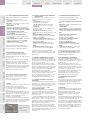
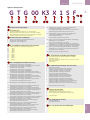
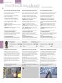
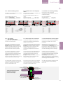
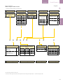
1.1.4 Informations présentées sur
l'étiquette de la face avant:
1.1.4 Overzicht van de labels op de
voorzijde:
1. Dénomination du produit
2. Code barres (avec numéro de série)
3. Code couleur indiquant le pouvoir de coupure
4. Tensions nominales
5. Courants nominaux
6. Certification et normes
7. Valeurs de pouvoir de coupure
8. Date de fabrication
1. Productbenaming
2. Barcode (met Serienummer)
3. Kleurcode voor Onderbrekingsgroep
4. Voltagewaarden
5. Stroomwaarden
6. Certificaties & Normen
7. Kortsluitgegevens
8. Fabricagedatum
1
3
2
4
5
7
6
8
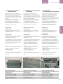
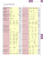
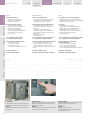
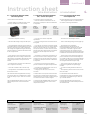
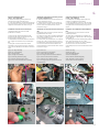
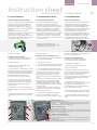
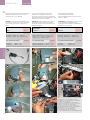
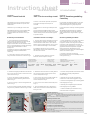
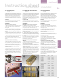
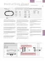
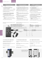
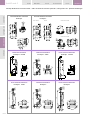
1.1.5 TOOLS needed for installation
Table 1.1 provides a list of the hand tools
required to install, operate and maintain the
EntelliGuard® G Circuit Breaker.
1.1.5 OUTILS nécessaires pour
l'installation
1.1.5 Gereedschap nodig bij de
installatie
Le tableau 1.1 fournit une liste des outils
nécessaires pour l'installation, la mise en service
et la maintenance du disjoncteur Entelliguard G.
Tabel 1.1 geeft een overzicht van de
handgereedschappen die nodig zijn voor de
installatie, bediening en het onderhoud van de
EntelliGuard® G Vermogenschakelaar.
Table 1.1: Required Hand Tools
Tableau 1.1: Outils nécessaires
Tabel 1.1: Vereiste Handgereedschappen
Tool Name / Function
Nom/fonction de l'outil
Naam gereedschap / Functie
Cluster pliers (GUNI):
To remove cluster contacts for inspection.
Clustertang (GUNI):
Om clustercontacten te verwijderen.
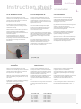
Allen key (5 mm):
To remove arc chutes for inspection and
maintenance. To remove or adjust fixed and
moving arcing contacts.
Outil pour pinces de sectionnement (GUNI):
pour enlever les pinces de sectionnement pour
inspection.
Tournevis (à tête plate, 8 mm):
pour le volet du logement de la manivelle de
manœuvre.
Clé Allen (5 mm):
pour démonter les chambres de coupure pour
l'inspection et la maintenance. Pour démonter
ou ajuster les pare-étincelles fixes et mobiles.
Allen key (4 mm):
To remove motor operator mounting screws.
Clé Allen (4 mm):
pour défaire les vis de la commande électrique.
Metric feeler gauges:
To check arcing contact gaps.
Jauges d'épaisseur métriques:
pour vérifier les interstices des pare-étincelles.
Pozidrive screwdriver (#2):
To remove mechanical and electronic
component mounting screws. To connect wiring
to secondary contact terminals.
Tournevis Pozidrive (nº2):
pour défaire les vis de montage des composants
mécaniques et électriques. Pour connecter les
câbles aux bornes de contact secondaires.
Pozidrive screwdriver (#3):
To remove front cover mounting screws.
Tournevis Pozidrive (nº3):
pour défaire les vis du capot avant.
TRIP UNIT
OPERATION
INSTALLATION SPECIFICATION
INTRO
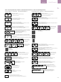
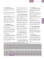
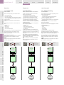
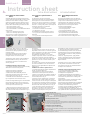
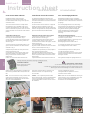
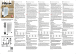
1.1.4 Front label data overview:
1. Product Denomination
2. Bar code (with Serial number)
3. Colour Code indicating Interruption Tier
4. Voltage Ratings
5. Current Ratings
6. Certifications & Standards
7. Short Circuit Interruption data
8. Manufacturing Date
Screwdriver (8 mm flat):
To operate racking aperture shutter drive.
1.1-06
Schroevendraaier (8 mm plat):
Voor bediening van sluiter van de
inrijdhendelschacht opening.
Inbussleutel (5 mm):
Voor het verwijderen van bluskamers voor
inspectie en onderhoud. Voor het verwijderen
van vaste en bewegende vonkcontacten.
Inbussleutel (4 mm):
Voor het verwijderen van montageschroeven
van de motorbediening.
Voelermaat:
Ter controle van de ruimte tussen
vonkcontacten.
Kruiskop schroevendraaier (#2):
Voor het verwijderen van montageschroeven
van mechanische en elektronische onderdelen.
Voor het aansluiten van secundaire
contactklemmenborden.
Kruiskop schroevendraaier (#3):
Voor het verwijderen van montageschroeven
van de cover aan de voorzijde.
EntelliGuard G
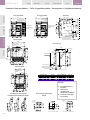
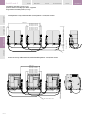
BREAKER
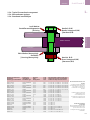
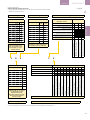
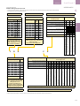
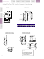
BLOCK A
BORNIER A
BLOK A
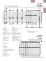
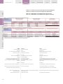
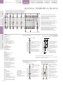
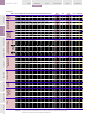
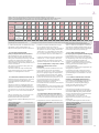
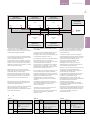
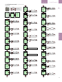
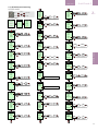
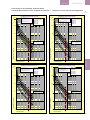
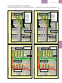
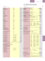
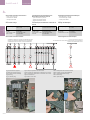
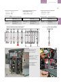
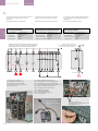
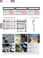
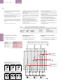
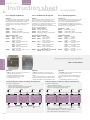
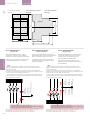
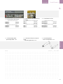
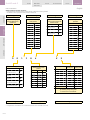
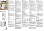
STANDARD CONNECTION SCHEME FOR TERMINAL BLOCK A
SCHÉMA DE CONNEXION STANDARD POUR LE BORNIER A
STANDAARD AANSLUITSCHEMA VOOR KLEMMENBORD A
LP1
A3
A9
A7
A5
A14
A12
31
A16
A18
33
11
21
A20
A22
A24
98
96
SPR
BAT
D1
C3
D1
C1
M
32
58
C2
D2
C4
D2
ST1
UVR1
CC
UVR2
A4
A6
A8
A10
34
12
22
24
A15
A13
A17
A19
A21
Indication:
LP1: statut d'armement des ressorts
LP2: disjoncteur ouvert
LP3: disjoncteur fermé
LP4: défaut
LP5: disjoncteur prêt à fermer
LP6: EE alimenté
LP7: DMT non alimenté
LP8: DEC alimenté
LP9: DEC 2 alimenté/DMT 2 non alimenté
LP10: blocage interverrouillage réseau
LP11: disjoncteur en position DÉBROCHÉ
LP12: disjoncteur en position TEST
LP13: disjoncteur en position EMBROCHÉ
CC: Closing coil
ST: Shunt release
UVR: Undervoltage release
SPR: Spring charge status
RTC: Ready to close status
M: Motor operator
BAT: Bell alarm trip
CCC: Command closing coil
NI: Network Interlock
EE: électro d'enclenchement
DEC: déclencheur à émission de courant
DMT: déclencheur à manque de tension
SAR: statut d'armement des ressorts
PAF: statut prêt à fermer
CE: commande électrique
CSD: contact de signalisation de défaut
EEC: électro d'enclenchement de commande
IR: interverrouillage réseau
A35
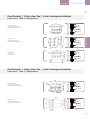
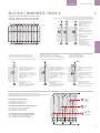
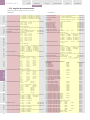
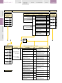
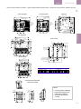
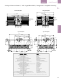
BLOCK B
BORNIER B
BLOK B
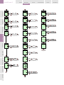
STANDARD CONNECTION SCHEME FOR TERMINAL BLOCK B
SCHÉMA DE CONNEXION STANDARD POUR LE BORNIER B
STANDAARD AANSLUITSCHEMA VOOR KLEMMENBORD B
B6
81
71
82
72
B5
A25
..more details see chapter 1.3.5
...pour de plus amples détails, voir chapitre 1.3.5
...meer details zie hoofdstuk 1.3.5
B4
CC: Inschakelspoel
ST: Uitschakelspoel
UVR: Onderspanning Inschakelspoel
SPR: Toestand veer
RTC: Gereed om te sluiten-status
M: Motorbediening
BAT: Bellalarm
CCC: Commando Inschakelspoel
NI: Netwerkvergrendeling
A23
LP3
LP2
Indication:
LP1: Spring charge status
LP2: Breaker open
LP3: Breaker closed
LP4: Fault
LP5: Breaker ready to close
LP6: CC powered
LP7: UVR not powered
LP8: ST powered
LP9: ST2 powered / UVR2 not powered
LP10: Network Interlock lockout
LP11: Breaker in DISCONNECTED position
LP12: Breaker in TEST position
LP13: Breaker in CONNECTED position
Indicatie:
LP1: Toestand veer
LP2: Schakelaar open
LP3: Schakelaar gesloten
LP4: Fout
LP5: Schakelaar gereed om te sluiten
LP6: CC bekrachtigd
LP7: UVR niet bekrachtigd
LP8: ST bekrachtigd
LP9: ST2 bekrachtigd/UVR2 niet bekrachtigd
LP10: Netwerkvergrendeling
LP11: Vermogenschakelaar in UITGEREDEN positie
LP12: Vermogenschakelaar in TEST positie
LP13: Vermogenschakelaar in INGEREDEN positie
95
14
T
ML
A2
A34
13
23
57
M2
A33
INTRO
LP4
A1
M1
1.1
B8
61
B7
B10
51
62
B9
52
B11
B12
B17
B19
B21
B23
B25
41
83
73
63
53
43
42
84
74
64
54
44
B13
B18
B20
B22
B24
B26
1.1-07
EntelliGuard G
INTRO
BREAKER
LOCKS
ACCESSORIES
TESTS
APPENDIX
TRIP UNIT
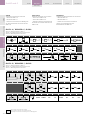
Table des matières:
Inhoud:
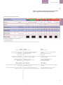
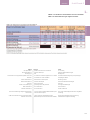
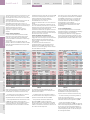
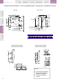
Table 1.2: Environmental Conditions
Tableau 1.2: Conditions environnementales
Tabel 1.2: Milieuvoorwaarden
Table 1.6: IEC 60947 AC/DC Version Performance
Characteristics
Tableau 1.6: Performances de la version c.a./c.c.
CEI 60947
Tabel 1.6: IEC 60947 AC/DC Versie Prestatieeigenschappen
Table 1.7: IEC 60947 AC/DC Version Rated
Endurance Specifications
Tableau 1.7: Spécifications d'endurance de la
version c.a./c.c. CEI 60947
Tabel 1.7: IEC 60947 AC/DC Versie Nominale
Uithoudings-eigenschappen
Table 1.9: Non-Automatic CB/Switch, IEC Version
Tableau 1.9: Interrupteur, version CEI
Table 1.10: Non-Automatic CB/Switch Endurance
Specifications
Tableau 1.10: Spécifications d'endurance de
l'interrupteur
Tabel 1.9: Niet-Automatische CB/Schakelaar, IEC
Versie
Tabel 1.10: Niet-Automatische CB/Schakelaar,
Uithoudingsspecificaties
Table 1.11: Connection options for breaker in
fixed pattern
Tableau 1.11: Options de connexion du
disjoncteur fixe
Tabel 1.11: Aansluitopties voor
vermogenschakelaar in vaste uitvoering
Table 1.12: Connection options for breaker in
draw out pattern
Tableau 1.12: Options de connexion du
disjoncteur débrochable
Tabel 1.12: Aansluitopties voor
vermogenschakelaar in uitrijdbare uitvoering
Table 1.15: Agency Certification
Tableau 1.15: Certification officielle
Tabel 1.15: Certificatie van Distributeur
OPERATION
INSTALLATION SPECIFICATION
INTRO
Content:
TRIP UNIT
n o t e
1.2-00
.
.
.
.
.
.
.
.
.
.
.
.
n o t e s
.
.
.
.
.
.
.
.
.
.
.
.
.
.
.
.
.
.
.
.
.
.
.
.
.
.
.
.
.
.
.
.
.
.
.
.
.
.
.
.
.
.
.
.
.
.
.
.
. . . . . . . . . . . . . . . . . . . . . . . . . . . .
. . . . . . . . . . . . . . . . . . . . . . . . . . . .
. . . . . . . . . . . . . . . . . . . . . . . . . . . .
. . . . . . . . . . . . . . . . . . . . . . . . . . . . .
.
.
.
.
.
.
.
.
.
.
.
.
.
.
.
.
.
.
.
.
|
.
.
.
.
.
.
.
.
n o t i t i e s
.
.
.
.
.
.
.
.
.
.
.
.
.
.
.
.
. .
. .
. .
.
EntelliGuard G
1.2 PRODUCT SPECIFICATIONS
1.2 SPÉCIFICATIONS DU PRODUIT
1.2 PRODUCTSPECIFICATIES
Tables
Tableaux
Tabellen
AVERTISSEMENT:
WAARSCHUWING:
Assurez-vous que seul le personnel qualifié
installe, utilise et procède à la maintenance de
tous les équipements électriques.
Zorg ervoor dat enkel gekwalificeerd personeel
elektrische apparatuur installeert, bedient,
onderhoudt en herstelt.
WARNING:
Ensure only qualified personnel install, operate,
service and maintain all electrical equipment.
Table 1.2: Environmental Conditions / Tableau 1.2: Conditions environnementales / Tabel 1.2: Milieuvoorwaarden
Characteristic
Caratéristique
Eigenschap
Parameter
Paramètre
Parameter
Ambient Operating
Extended Ambient Operating
Storage
20% RH to 95% RH
-5 ºC to 70 ºC
-20 ºC to -5 ºC
-40 ºC to 70 ºC
Cold
Dry Heat
Damp Heat
Salt
Change of Temperature
Damp Heat cyclic
Climatic
IEC 68-2-1
IEC 68-2-2
IEC 68-2-3
IEC 68-2-11
IEC 68-2-14
IEC 68-2-30
IEC 721
Vibration
Electromagnetic compatibility
Fungus resistance
(random and sinusoidal)
1 G max. , 50 Hz to 500 Hz in X, Y, Z directions
per IEC 60947-2 appendix F.
per ASTM G21
Altitude Correction factors
Altitude
Voltage (Ue)
Current (In)
<30 dB
>2000 m
1
1
Closing Coil, Shunt releases
Motor Operator, Undervoltage release
Accessories
20,000 operations
12,500 operations
12,500 operations
Temperature:
Humidity
Noise level
Endurance:
English
Accessories
Altitude
Altitude Correction factors
Ambient (surrounding circuit breaker)
appendix F.
Change of Temperature
Characteristic
Climatic
Closing Coil
Cold
Current (In)
Damp Heat
Damp Heat cyclic
Dry Heat
Electromagnetic compatibility
Endurance
Environmental Conditions
Fungus resistance
Humidity
in X, Y, Z directions
Motor Operator
Noise level
Operating
operations
Parameter
Salt
Shunt Release
Storage
Temperature
Undervoltage Release
Vibration (random and sinusoidal)
Voltage (Ue)
2500 m
0,95
0,99
1.2
SPECIFICATION
BREAKER
4000 m
0,8
0,96
Français
Accessoires
Altitude
Facteurs de correction d'altitude
Température ambiante (autour du disjoncteur)
Annexe F
Changement de température
Caractéristique
Climatique
Électro d'enclenchement
Froid
Courant (In)
Chaleur humide
Chaleur humide cyclique
Chaleur sèche
Dutch
Accessoires
Hoogte
Hoogtecorrectiefactoren
Omgevingstemperatuur (rond de vermogenschakelaar)
appendix F.
Temperatuurwijziging
Eigenschap
Klimatologisch
Inschakelspoel
Koude
Stroom (In)
Vochtige hitte
Vochtige hitte cyclisch
Droge hitte
Compatibilité électromagnétique
Endurance
Conditions environnementales
Résistance aux champignons
Humidité
Dans les directions X, Y, Z
Commande électrique
Niveau sonore
Elektromagnetische compatibiliteit
Levensduur
Milieuvoorwaarden
Schimmelweerstand
Luchtvochtigheid
in X, Y, Z richtingen
Motorbediening
Geluidsniveau
De fonctionnement
Opérations
Paramètre
Sel
Déclencheur à émission de courant
Stockage
Température
Déclencheur à manque de tension
Vibrations (aléatoires et sinusoïdales)
Tension (Ue)
Bediening
acties
Parameter
Zout
Uitschakelspoel
Opslag
Temperatuur
Onderspanningspoel
Vibratie (willekeurig en sinusoïdaal)
Voltage (Ue)
1.2-01
EntelliGuard G
INTRO
BREAKER
LOCKS
ACCESSORIES
TESTS
APPENDIX
TRIP UNIT
TRIP UNIT
OPERATION
INSTALLATION SPECIFICATION
INTRO
Tableau 1.6 Performance conformément à la norme CEI 60947-2
Tabel 1.6 Prestaties volgens IEC 60947-2
English
GG32,40 or GJ32,40
1) GH is the limited de-rating version
1) GG is the standard type
Français
GG32,40 ou GJ32,40
1) GH est la version à déclassement limité
1) GG est la version standard
Dutch
GG32,40 of GJ32,40
1) GH is de gelimiteerde de-rating uitvoering
1) GG is het standaardtype
Dénomination du disjoncteur de puissance
Catégorie d'emploi
Version débrochable à pinces de sectionnement doubles
Taille
Déclencheur HSIOC réglé sur:
Interrupteur
Benaming van de Open Vermogenschakelaar
Gebruikscategorie
Dubbelcluster uitrijdbare uitvoering
Bouwgrootte
HIOSC spoel ingesteld op:
Isolator
Protection de fermeture sur court-circuit réglée sur:
Nb de pôles en série:
Nombre de
Piekstroomspoel ingesteld op:
aantal polen in serie
Aantal
ON et OFF positif
Type de disjoncteur de puissance
Positieve AAN & UIT
Vermogenschakelaartype
Courant thermique conventionnel In
Tension assignée de tenue aux chocs Uimp
Tension assignée d'isolement Ui
Tension assignée de fonctionnement Ue
Nominale stroomsterkte In
Nominale impulsweerstandspanning Uimp
Nominale isolatiespanning Ui
Nominaal werkingsvoltage Ue
Service breaking capacity Ics [kA]
Short Circuit Making current Icm
Short Circuit Withstand Icw (kA)
Pouvoir assigné de coupure de service Ics [kA]
Courant de fermeture sur court-circuit Icm
Courant assigné de courte durée admissible (Tenue au
court-circuit) Icw (kA)
Dienstkortsluitschakelvermogen lcs [kA]
Kortsluitpiekstroom Icm
Kortsluitweerstand lcw (kA)
Single cluster drawout contruction
Suitable for use as a isolator
Version débrochable à pince de sectionnement simple
Adapté à l'emploi comme interrupteur
Enkel cluster uitrijdbare uitvoering
Geschikt voor gebruik als isolator
Ultimate breaking capacity Icu [kA]
Pouvoir assigné de coupure ultime Icu [kA]
Uiterste kortsluitschakelvermogen lcu [kA]
Air Circuit Breaker Denomination
Category of use
Dual cluster drawout construction
Envelope type
HIOSC release set at:
Isolator
Making Current Release set at:
nr. of poles in series
Number of
Positive ON & OFF
Power Circuit Breaker type
Rated current In
Rated impulse withstand voltage Uimp
Rated insulation voltage Ui
Rated operational voltage Ue
1.2-02
BREAKER
EntelliGuard G
1.2
SPECIFICATION
Tableau 1.7: Endurance conformément à la norme CEI 60947-2
Tabel 1.7: Weerstandsvermogen volgens IEC 60947-2
English
GG32,40 or GJ32,40
Français
GG32,40 ou GJ32,40
Dutch
GG32,40 of GJ32,40
Air Circuit Breaker Denomination
CO operations
Electrical Endurance
Envelope type
Dénomination du disjoncteur de puissance
Opérations de fermeture et ouverture
Endurance électrique
Taille
Benaming van de Open Vermogenschakelaar
CO -acties
Elektrisch weerstandsvermogen
Bouwgrootte
For Endurance in DC applications
...please refer to the IEC 60947
Pour l'endurance dans les applications c.c. veuillez
vous référer à la norme CEI 60947
Voor Weerstandsvermogen bij DC-toepassingen,
raadpleeg IEC 60947
Endurance mécanique
Type de disjoncteur de puissance
Courant assigné In
Mechanisch weerstandsvermogen
Vermogenschakelaartype
Nominale stroomsterkte In
Avec maintenance
Sans maintenance
Met onderhoud
Zonder onderhoud
4) GG is the standard type (Single cluster drawout
construction)
4) GG est la version standard (débrochable à pince
de sectionnement simple)
4) GG is het standaardtype (Enkel cluster uitrijdbare
uitvoering)
4) GH is the limited de-rating version (Dual cluster
drawout construction)
4) GH est la version à déclassement limité
(débrochable à pinces de sectionnement doubles)
4) GH is de gelimiteerde de-rating uitvoering
(Dubbelcluster uitrijdbare uitvoering)
Mechanical Endurance
Power Circuit Breaker type
Rated current In
With Maintenance
Without Maintenance
1.2-03
EntelliGuard G
INTRO
BREAKER
LOCKS
ACCESSORIES
TESTS
APPENDIX
TRIP UNIT
TRIP UNIT
OPERATION
INSTALLATION SPECIFICATION
INTRO
Tableau 1.9: Performance conformément à la norme CEI 60947-3
Tabel 1.9: Prestaties volgens IEC 60947-3
English
GK is the limited de-rating version
GJ is the standard type
1) The GW type is a sub variant of the GJ type and
the GZ a sub variant of the GK type, both equipped
with a MCR release.
HIOSC release set at: kA rms
Isolator Denomination
Making Current Release set at (1) kA rms
Non Auto
Number of Poles
Dutch
GK is de gelimiteerde de-rating uitvoering
GJ is het standaardtype
1) GW est une variante de GJ et GZ est une variante 1) Het GW type is een subvariant van het GJ type en de
de GK, les deux sont équipées d'une protection de GZ is een subvariant van het GK type, beiden uitgerust
fermeture sur court-circuit.
met een MCR -spoel.
Déclencheur HSIOC réglé sur: kA rms
Dénomination de l'interrupteur
HIOSC spoel ingesteld op: kA rms
Benaming isolator
Protection de fermeture sur court-circuit réglée à (1) Piekstroomspoel ingesteld op (1) kA rms
kA rms
Version Interrupteur
Nombre de pôles
Non Auto
Aantal polen
ON et OFF positif
Type de disjoncteur de puissance
Positieve AAN & UIT
Vermogenschakelaartype
Rated current In
Rated impulse withstand voltage Uimp [Kilovolt]
Rated insulation voltage Ui (Volts)
Rated operational voltage Ue Volts AC
Courant assigné In
Tension assignée de tenue aux chocs Uimp [kV]
Tension nominale d'isolation Ui (volts)
Tension assignée de fonctionnement Ue volts c.a.
Nominale stroomsterkte In
Nominale impulsweerstandspanning Uimp [Kilovolt]
Nominale isolatiespanning Ui (Volt)
Nominaal werkingsvoltage Ue Volt AC
second
Short Circuit Making current Icm 220-500V AC kA
Peak
seconde
Pouvoir assigné de fermeture en court-circuit Icm
220-500 V c.a. crête
tweede
Kortsluitstroomsterkte lcm 220-500V AC kA piek
Positive ON & OFF
Power Circuit Breaker type
Short Circuit Withstand Icw (kA)
Suitable for use as a isolator
1.2-04
Français
GK est la version à déclassement limité
GJ est la version standard
Courant assigné de courte durée admissible (Tenue Kortsluitweerstand lcw (kA)
au court-circuit) Icw (kA)
Adapté à l'emploi comme interrupteur
Geschikt voor gebruik als isolator
BREAKER
EntelliGuard G
1.2
SPECIFICATION
Tableau 1.10: Endurance conformément à la norme CEI 60947
Tabel 1.10: Weerstandsvermogen volgens IEC 60947
English
CO operations at
Electrical Endurance
Envelope type
Français
Opérations d'ouverture et fermeture à
Endurance électrique
Taille
Dutch
CO -acties bij
Elektrisch weerstandsvermogen
Bouwgrootte
Pour l'endurance dans les applications c.c. veuillez
vous référer à la norme CEI 60947
Voor Weerstandsvermogen bij DC-toepassingen,
raadpleeg IEC 60947
Dénomination de l'interrupteur
Benaming isolator
Endurance mécanique
Version interrupteur
Type de disjoncteur de puissance
Mechanisch weerstandsvermogen
Non Auto
Vermogenschakelaartype
Avec maintenance
Sans maintenance
Met onderhoud
Zonder onderhoud
4) GJ is the standard type (Single cluster drawout
construction)
4) GJ est la version standard (débrochable à pince
de sectionnement simple)
4) GJ is het standaardtype (Enkel cluster uitrijdbare
uitvoering)
4) GK is the limited de-rating version (Dual cluster
drawout construction)
4) GK est la version à déclassement limité
(débrochable à pinces de sectionnement doubles)
4) GK is de gelimiteerde de-rating uitvoering
(Dubbelcluster uitrijdbare uitvoering)
For Endurance in DC applications please refer to the
IEC 60947
Isolator Denomination
Mechanical Endurance
Non Auto
Power Circuit Breaker type
With Maintenance
Without Maintenance
1.2-05
EntelliGuard G
INTRO
BREAKER
LOCKS
ACCESSORIES
TESTS
APPENDIX
TRIP UNIT
INTRO
Tableau 1.11: Options de connexion pour disjoncteur fixe EntelliGuard
Tableau 1.12: Options de connexion du disjoncteur débrochable
TRIP UNIT
OPERATION
INSTALLATION SPECIFICATION
Tabel 1.11: Aansluitopties voor EntelliGuard in vaste uitvoering
Tabel 1.12 Aansluitopties voor EntelliGuard in uitrijdbare uitvoering
English
Cassette available
Envelope
Front access Busbar Connection
Français
Partie fixe disponible
Taille
Prise avant
Dutch
Cassette beschikbaar
Bouwgrootte
Busbaraansluiting aan de voorzijde
horizontale ou verticale
horizontaal of verticaal
Optional
Power Circuit Breaker type
En option
Type de disjoncteur de puissance
Optioneel
Vermogenschakelaartype
Ratings
Rear Access Horizontal Busbar Connection
Rear access Vertical Busbar Connection
Rear access Vertical ONLY Busbar Connection
Remarks
Courants assignés
Prise arrière horizontale
Prise arrière verticale
Prise arrière verticale SEULEMENT
Remarques
Ratings
Horizontale Busbaraansluiting aan de achterzijde
Verticale Busbaraansluiting aan de achterzijde
ENKEL Verticale Busbaraansluiting aan de achterzijde
Opmerkingen
Standard
Standaard
The Envelope 2 type cassette is supplied with ..
La partie fixe taille 2 est fournie avec..
De Bouwgrootte 2 cassette wordt geleverd met ..
Universal Connection Rear Access Connections
Prise arrière universelle
Universele aansluitingen voor de achterzijde
horizontal or Vertical
Standard
Universele Busbaraansluitingen voor de achterzijde
Universal Rear Access Busbar Connection
When used horizontally it has a
maximum rating of..
When used vertically it has ..
1.2-06
Utilisée à l'horizontale, ses caractéristiques assignées
maximales sont de...
Bij horizontaal gebruik heeft deze een maximale rating van..
Utilisée à la verticale, ...
Bij verticaal gebruik heeft deze ..
EntelliGuard G
BREAKER
1.2
Table 1.15: Agency Certification
Tableau 1.15: Certification officielle
Tabel 1.15: Certificatie van Distributeur
(All industry standards referenced in this table are
the latest version at the time the product is
sold.)
(Toutes les normes listées dans ce tableau font
référence à la dernière version disponible au
moment de la vente du produit)
(Alle industriële normen in deze tabel zijn de meest
recente versie op het ogenblik van verkoop van het
product.)
Standard Number / Title
Numéro de la norme / Titre
Normnummer
-----------------------------------------------------------IEC 60947 Part 1
Low Voltage Switchgear and Control Gear General
Rules
-----------------------------------------------------------CEI 60947 Partie 1
Appareillage à basse tension - Règles générales
-----------------------------------------------------------IEC 60947 deel 1
Algemene richtlijnen voor Laagvoltage schakel- en
bedieningsuitrustingen
IEC 60947 Part 2
Low Voltage Switchgear and Control Gear CircuitBreakers
CEI 60947 Partie 2
Appareillage à basse tension - Disjoncteurs
IEC 60947 deel 2
Vermogenschakelaars voor Laagvoltage schakel- en
bedieningsuitrustingen
IEC 60947 Part 5
Low Voltage Switchgear and Control Gear
Accessories
CEI 60947 Partie 5
Appareillage à basse tension - Accessoires
IEC 60947 deel 5
Accessoires voor Laagvoltage schakel- en
bedieningsuitrustingen
IEC 60947 Part 3
Low Voltage Switchgear and Control Gear Switches,
Disconnects, Switch-Disconnects and FuseCombination Units.
CEI 60947 Partie 3
Appareillage à basse tension - Interrupteurs,
sectionneurs, interrupteurs-sectionneurs et
combinés-fusibles.
IEC 60947 deel 3
Schakelaars voor Laagvoltage schakel- en
bedieningsuitrustingen, spoelen, schakelspoelen en
zekeringcombinatie-units.
-----------------------------------------------------------IEC 68-2-1
Cold
IEC 68-2-2
Dry Heat
IEC 68-2-3
Damp Heat
IEC 68-2-6
Vibration
IEC 68-2-11 Salt
IEC 68-2-14 Change of Temperature
IEC 68-2-27 Shock test
IEC 68-2-29 Bump
IEC 68-2-30 Damp Heat cyclic e
IEC 68-2-31 Drop test
IEC 721
Climatic
-----------------------------------------------------------CEI 68-2-1
Froid
CEI 68-2-2
Chaleur sèche
CEI 68-2-3
Chaleur humide
CEI 68-2-6
Vibrations
CEI 68-2-11 Sel
CEI 68-2-14 Changement de température
CEI 68-2-27 Test de choc
CEI 68-2-29 Secousses
CEI 68-2-30 Chaleur humide cyclique
CEI 68-2-31 Test de chute
CEI 721
Climatique
-----------------------------------------------------------IEC 68-2-1
Koude
IEC 68-2-2
Droge hitte
IEC 68-2-3
Vochtige hitte
IEC 68-2-6
Trilling
IEC 68-2-11
Zout
IEC 68-2-14
Temperatuurwijziging
IEC 68-2-27
Schoktest
IEC 68-2-29
Botsen
IEC 68-2-30
Vochtige hitte cyclisch
IEC 68-2-31
Valtest
IEC 721
Klimatisch
------------------------------------------------------------
------------------------------------------------------------
------------------------------------------------------------
GB14048
China Standards and CCC Mark
ABS
(American Bureau of Shipping)
Germanischer Lloyds
GB14048
Normes chinoises et marquage CCC
ABS
(American Bureau of Shipping)
Germanischer Lloyds
GB14048 Chinese normen en CCC markering
ABS
(American Bureau of Shipping)
Germanischer Lloyds
n o t e
.
.
.
.
.
.
.
.
.
.
.
.
.
.
.
.
.
.
.
.
.
.
.
.
.
.
.
.
.
.
.
.
.
.
.
.
.
.
.
n o t e s
.
.
.
.
.
.
.
.
.
.
.
.
.
.
.
.
.
.
.
.
.
.
.
.
.
.
.
.
.
.
.
.
.
.
.
.
.
.
.
.
.
.
.
.
.
.
.
.
.
.
.
.
.
.
.
.
.
.
.
.
.
.
.
.
.
.
.
.
.
.
.
.
.
.
.
.
.
.
.
.
.
.
.
.
.
.
.
.
.
.
.
.
.
.
.
.
.
.
.
.
.
.
.
.
.
.
.
.
.
.
.
.
.
.
.
.
.
.
.
.
.
.
.
.
.
.
.
.
.
.
.
.
.
.
.
.
.
.
.
.
.
.
.
.
.
.
.
.
.
.
.
.
.
.
.
.
.
.
.
.
.
.
.
.
.
.
.
.
.
.
.
.
.
.
.
.
.
.
.
.
.
.
.
.
.
.
.
.
.
.
.
.
.
.
.
.
.
.
.
.
.
.
.
.
.
.
.
.
.
.
.
.
.
.
.
.
.
.
.
.
.
.
.
.
.
.
.
.
.
.
.
.
.
.
.
.
.
.
.
.
.
.
.
.
.
.
.
.
.
.
.
.
.
.
.
.
.
.
.
.
.
.
.
.
.
.
.
.
.
.
.
.
.
.
.
.
.
.
.
.
.
.
.
.
.
.
.
.
.
.
.
.
.
.
.
.
.
.
.
.
.
.
.
.
.
.
.
.
.
.
.
.
.
.
.
.
.
.
.
.
.
.
.
.
.
.
.
.
.
.
.
.
.
.
.
.
.
.
.
.
.
.
.
.
.
.
.
.
.
.
.
.
.
.
.
.
.
.
.
.
.
.
.
.
.
.
.
.
.
.
.
.
.
.
.
.
.
.
.
.
.
.
.
.
.
.
.
.
.
.
.
.
.
.
.
.
.
.
.
.
.
.
.
.
.
.
.
.
.
.
.
.
.
.
.
.
.
.
.
.
.
.
.
.
.
.
.
.
.
.
.
.
.
.
.
.
.
.
.
.
.
.
.
.
.
.
.
.
.
.
.
.
.
.
.
.
.
.
.
.
.
.
.
.
.
.
.
.
.
.
.
.
.
.
.
.
.
.
.
.
.
.
.
.
.
.
.
.
.
.
.
.
.
.
.
.
.
.
.
.
.
.
.
.
.
.
.
.
.
.
.
.
.
.
.
.
.
.
.
.
.
.
.
.
.
.
.
.
.
.
.
.
.
.
.
.
.
.
.
.
.
.
.
.
.
.
.
|
.
.
.
.
.
.
.
.
.
.
.
.
.
.
.
.
.
.
.
.
.
.
.
.
SPECIFICATION
Titel
n o t i t i e s
.
.
.
.
.
.
.
.
.
.
.
.
.
.
.
.
.
.
.
.
.
.
.
.
.
.
.
.
.
.
.
.
.
.
.
.
.
.
.
.
.
.
.
.
.
.
.
.
.
.
.
.
.
.
.
.
.
.
.
.
.
.
.
.
.
.
.
.
.
.
.
.
1.2-07
EntelliGuard G
INTRO
BREAKER
LOCKS
ACCESSORIES
TESTS
APPENDIX
TRIP UNIT
Table des matières
Inhoud
1.3.1 Lifting and Mounting
- Using Lifting Beams
1.3.1 Manutention et montage
- Utiliser un chariot de manutention et un adaptateur
1.3.1 Optillen en Monteren
- Gebruik van een Heftruck en Adapter
1.3.2 Fixed-Pattern Circuit Breaker
- Installation
1.3.2 Disjoncteur fixe
Installation
1.3.2 Vaste Vermogenschakelaar
- Installatie
1.3.3 Drawout Pattern Circuit Breaker
- Installation
- Removal from Cassette
- Mounting in Cassette
1.3.3 Disjoncteur débrochable
Installation
Retrait de la partie fixe
Montage dans la partie fixe
1.3.3 Uitrijdbare Vermogenschakelaar
- Installatie
- Verwijdering uit de Cassette
- Plaatsing in de Cassette
1.3.4 Standard Bus Connection
of Fixed and/or Drawout Pattern
1.3.4 Raccordement standard
des versions fixes et débrochables
1.3.4 Standaard aansluitwijze
1.3.5 Secondary Disconnect Terminal Blocks
- Location
- Use
- Table -- General schematics
- Table -- Definition of connected devices
to Block A and Block B
1.3.5 Borniers de sectionnement secondaires
Emplacement
Utilisation
Tableau -- Schéma général
Tableau -- Définition des appareils
connectés au bornier A et au bornier B
1.3.5 Secundaire Ontkoppeling
Klemmenborden
- Locatie
- Gebruik
- Tabel -- Algemene schema's
- Tabel -- Definitie van aangesloten toestellen
naar Blok A en Blok B
OPERATION
INSTALLATION SPECIFICATION
INTRO
Content
TRIP UNIT
n o t e
.
.
.
.
.
.
.
.
.
.
.
.
.
.
.
.
.
.
.
.
.
.
.
.
.
.
.
.
.
.
.
.
.
.
.
.
.
.
.
.
.
.
n o t e s
.
.
.
.
.
.
.
.
.
.
.
.
.
.
.
.
.
.
.
.
.
.
.
.
.
.
.
.
.
.
.
.
.
.
.
.
.
.
.
.
.
.
.
.
.
.
.
.
.
.
.
.
.
.
.
.
.
.
.
.
.
.
.
.
.
.
.
.
.
.
.
.
.
.
.
.
.
.
.
.
.
.
.
.
.
.
.
.
.
.
.
.
.
.
.
.
.
.
.
.
.
.
.
.
.
.
.
.
.
.
.
.
.
.
.
.
.
.
.
.
.
.
.
.
.
.
.
.
.
.
.
.
.
.
.
.
.
.
.
.
.
.
.
.
.
.
.
.
.
.
.
.
.
.
. . . . . . . . . . . . . . . . . . . . . . . . . . . . .
. . . . . . . . . . . . . . . . . . . . . . . . . . . . .
. . . . . . . . . . . . . . . . . . . . . . . . . . . . .
. . . . . . . . . . . . . . . . . . . . . . . . . . . . .
. . . . . . . . . . . . . . . . . . . . . . . . . . . . .
. . . . . . . . . . . . . . . . . . . . . . . . . . . . .
. . . . . . . . . . . . . . . . . . . . . . . . . . . . .
. . . . . . . . . . . . . . . . . . . . . . . . . . . . .
. . . . . . . . . . . . . . . . . . . . . . . . . . . . .
. . . . . . . . . . . . . . . . . . . . . . . . . . . . .
. . . . . . . . . . . . . . . . . . . . . . . . . . . . .
. . . . . . . . . . . . . . . . . . . . . . . . . . . . .
. . . . . . . . . . . . . . . . . . . . . . . . . . . . .
. . . . . . . . . . . . . . . . . . . . . . . . . . . . . .
WARNING:
Ensure only qualified personnel install, operate,
service and maintain all electrical equipment.
Ensure lifting equipment has capability for
device being lifted.
Wear hard hat, gloves and safety shoes.
1.3-00
AVERTISSEMENT:
Assurez-vous que seul le personnel qualifié
installe, utilise et procède à la maintenance de
tous les équipements électriques.
Assurez-vous que l'équipement de manutention
est adapté à l'appareil concerné.
Portez un casque, des gants et des chaussures
de sécurité.
.
.
.
.
.
.
.
.
.
.
.
.
.
.
.
.
.
.
.
.
.
.
.
.
.
.
.
.
.
.
.
.
.
.
.
.
.
.
.
.
.
.
.
.
.
.
.
.
.
.
.
.
.
.
.
.
.
.
.
.
.
.
.
.
.
.
.
.
.
.
|
.
.
.
.
.
.
.
.
.
.
.
.
.
.
.
.
.
.
.
.
.
.
.
.
.
.
.
.
n o t i t i e s
.
.
.
.
.
.
.
.
.
.
.
.
.
.
.
.
.
.
.
.
.
.
.
.
.
.
.
.
.
.
.
.
.
.
.
.
.
.
.
.
.
.
.
.
.
.
.
.
.
.
.
.
.
.
.
.
WAARSCHUWING:
Zorg ervoor dat enkel gekwalificeerd personeel
elektrische apparatuur installeert, bedient,
onderhoudt en herstelt.
Zorg ervoor dat de hefuitrusting voldoende
capaciteit heeft om de toestellen te tillen.
Draag een veiligheidshelm, handschoenen en
veiligheidsschoenen.
.
.
.
.
.
.
.
.
.
.
.
.
.
.
.
.
.
.
.
.
.
.
.
.
.
.
.
EntelliGuard G
1.3 INSTALLATION
1.3 INSTALLATION
1.3 INSTALLATIE
CAUTION: Ensure circuit breaker and its
accessories are always used within their
designated ratings.
Do not allow the circuit breaker to hit a hard
surface while handling.
Do not drag or slide the circuit breaker across a
hard or rough surface.
ATTENTION: Assurez-vous que le disjoncteur
et ses accessoires sont toujours utilisés dans les
limites de leurs caractéristiques assignées.
Le disjoncteur ne doit pas heurter de surface
dure pendant la manutention.
Le disjoncteur ne doit pas être tiré ou glissé sur
une surface dure ou irrégulière.
Install the device in a dry, dust-free, noncorrosive environment. The environmental
conditions must be in compliance with the IEC
60947 requirements and/or the conditions
stated in this manual.
When the device is placed in environments
with conditions that deviate from those
mentioned in this manual please contact the
nearest GE Energy sales office.
Installez l'appareil dans un environnement sec,
sans poussière et non corrosif. Les conditions
environnementales doivent être conformes aux
exigences de la norme CEI 60947 et/ou aux
conditions indiquées dans ce manuel.
Lorsque l'appareil est placé dans des
environnements où les conditions ne sont pas
conformes à celles mentionnées dans ce
manuel, veuillez contacter le bureau de vente GE
le plus proche.
LET OP: Zorg ervoor dat de
vermogenschakelaar en accessoires enkel
gebruikt worden voor stroomwaarden waartoe
ze ontwikkeld zijn.
Zorg ervoor dat de vermogenschakelaar geen
hard oppervlak raakt bij manipulatie ervan.
Sleep of schuif de vermogenschakelaar nooit
over een hard of ruw oppervlak.
Installeer het toestel in een droge, stofvrije en
corrosievrije omgeving. De
omgevingsvoorwaarden moeten in
overeenstemming zijn met IEC 60947 en/of de
voorwaarden die omschreven zijn in deze
handleiding.
Wanneer het toestel geplaatst wordt in
omgevingen met omstandigheden die afwijken
van de in deze handleiding vermelde
omstandigheden, raadpleeg het dichtstbijzijnde
verkoopkantoor van GE Energy.
Unpacking Circuit Breaker
Before unpacking it is strongly recommended
that the shipping container is inspected and that
any undue damage incurred during transport
and handling is recorded. If any damage is
observed please contact the carrier mentioning
order number, shipping data and all other
relevant data before proceeding.
Déballage du disjoncteur
Avant de déballer le disjoncteur, il est vivement
recommandé d'inspecter l'emballage de
transport et de noter tout dommage excessif
subi pendant le transport et la manutention. En
cas de dommage, contacter le transporteur en
mentionnant le numéro de commande, les
informations d'expédition ainsi que toute
information pertinente avant de continuer.
-- Défaire les sangles de serrage et retirer avec
précaution le couvercle de la caisse.
-- Enlever les pièces d'emballages et la
documentation.
-- Enlever les manuels d'installation et
d'utilisation, et les conserver pour leur utilisation
ultérieure. Vérifier qu'ils sont dans la langue
choisie. Dans le cas contraire, contacter le
bureau de vente GE le plus proche.
-- Vérifier la présence dans la caisse
d'accessoires tels que les Tés de connexion ou
autres pièces livrées non montées dans certains
cas.
-- L'appareil est livré boulonné au fond de la
caisse/palette. Desserrer et enlever ces boulons
pour extraire le disjoncteur de la caisse/palette.
-- Unbind the banding straps and carefully
remove the box/pallet top cover.
-- Remove any additional packing materials and
relevant documentation.
– Locate and remove the installation and
operating manual. Retain for later use &
reference . Verify if these are in the language
required. If not please contact the nearest GE
Energy sales office.
-- Check packaging box for accessories as
connection pads and other hardware that , in
some cases, are delivered unmounted.
-- The Device is normally delivered bolted to the
box/pallet bottom. Loosen and remove these
bolts to removed breaker from the box/pallet.
1.3
INSTALLATION
BREAKER
Vermogenschakelaar uit de Verpakking nemen
Alvorens u het toestel uit de verpakking neemt,
wordt aanbevolen om de verpakking grondig te
inspecteren en enige transportschade te
registreren. Indien er enige schade wordt
vastgesteld, neem contact op met de
transportfirma en vermeld ordernummer,
transportgegevens en alle andere relevante
gegevens alvorens verder te gaan.
-- Verwijder de sluitbanden en verwijder
voorzichtig de bovenzijde van de doos.
-- Verwijder enige aanvullende
verpakkingsmaterialen en relevante
documentatie.
-- Zoek en verwijder de installatie- en
bedieningshandleiding. Bewaar deze voor later
gebruik & raadpleging. Controleer of ze in de
juiste taal geleverd zijn. Indien dit niet het geval
is, neem contact op met het dichtstbijzijnde
verkoopkantoor van GE Energy.
-- Controleer de doos op aanwezigheid van
accessoires zoals aansluitingskussens en andere
hardware die, in bepaalde gevallen, afzonderlijk
en ongemoteerd geleverd worden.
-- Het toestel is vastgeschroefd aan de
onderzijde van de doos. Maak de bouten los en
verwijder ze om het toestel uit de doos te
nemen.
Mounting location
Emplacement des boulons
Montagelocatie
Fig. 1.2: Lifting Beam
Fig. 1.2: Adaptateur de manutention
Fig. 1.2: Hefarm
1.3-01
EntelliGuard G
INTRO
BREAKER
LOCKS
ACCESSORIES
TESTS
APPENDIX
TRIP UNIT
OPERATION
INSTALLATION SPECIFICATION
INTRO
TRIP UNIT
1.3.1 Hoisting/Lifting Accessories
1.3.1 MANUTENTION ET MONTAGE
1.3.1 Hijs/hef accessories
Each EntelliGuard breaker is equipped with a set
of hoisting eyes. To lift the breaker using
standard hoisting equipment, specifically
designed adapters can be linked to the hoisting
eyes. Two kinds of adapters or beams, one for
use with Envelope 1&2 breakers (GLB1) and a
second for the larger envelope 3 breaker (GLB3)
are available.
Utiliser un chariot de manutention et un
adaptateur
Ces accessoires sont disponibles en option pour
faciliter la manutention des disjoncteurs. Le type
standard convient à la manutention des
disjoncteurs de taille 1 et 2, et un adaptateur est
disponible pour utiliser le même chariot avec les
disjoncteurs de taille 3.
Elke Entelliguard breaker is uitgevoerd met een
set hijsogen. Om de Entelliguard breaker te
hijsen worden de standaard hijsogen gebruikt,
speciaal hiervoor ontworpen adaptors kunnen
door de hijsogen geplaatst worden. Er zijn 2
soorten hijs of hefadaptors beschikbaar, voor
bouwgrootte 1& 2 (GLB1), en voor bouwgrootte 3
(GLB2).
1.3.2 Fixed Circuit Breaker
Installation
1.3.2 Installation du disjoncteur fixe
1.3.2 Installatie van de Vaste
Vermogenschakelaar
1. Ensure adequate clearance above the circuit
breaker to allow removal of the arc chutes and
inspection of the arcing contacts.
1. Zorg voor voldoende vrije ruimte boven de
vermogenschakelaar voor verwijdering van de
bluskamers en inspectie van de vonkcontacten.
3. A clearly marked grounding point is provided
on either side of the circuit breaker.
1. Vérifier que la distance de sécurité au-dessus
du disjoncteur est suffisante pour retirer les
chambres de coupure et inspecter les pareétincelles.
2. Fixer le disjoncteur en position sur une
structure de support adéquate avec quatre
boulons M8 avec un couple de serrage de 25
Nm.
3. Un point de mise à la terre est clairement
marqué de chaque côté du disjoncteur.
2. Bevestig de vermogenschakelaar op een
geschikte ondersteunende structuur d.m.v. vier
M8 bouten, draai aan tot 25 Nm.
3. Er is een duidelijk gemarkeerd aardingspunt
aanwezig op beide zijden van de
vermogenschakelaar.
1.3.3 Drawout Circuit Breaker
Installation
1.3.3 Installation du disjoncteur
débrochable
1.3.3 Installatie van de Uitrijdbare
Vermogenschakelaar
Drawout type circuit breakers are normally
delivered already mounted in cassettes.
Les disjoncteurs débrochables sont livrés déjà
monté dans la partie fixe.
1. Retirer le disjoncteur de sa partie fixe en
utilisant la procédure de retrait décrite dans la
section 1.4.
2. Placer la partie fixe comme il convient dans le
tableau de distribution. La partie fixe peut être
soulevée à la main. Cependant, en cas
d'utilisation du chariot de manutention ou de
tout autre appareil de manutention, utiliser les
quatre trous de manutention qui se trouvent à
l'avant et à l'arrière de la partie fixe.
3. Mettre la partie fixe en place et connecter les
câbles/barres omnibus d'entrée et de sortie.
S'assurer que les déflections/contraintes
mécaniques à l'arrière de la partie fixe sont les
plus réduites possible lors de la connexion des
barres omnibus.
4. Monter la partie fixe à l'aide de quatre
boulons M8 avec un couple de serrage de 25 Nm
sur les points de montage avant et arrière.
Dit type vermogenschakelaars worden
normaliter voorgemonteerd in cassettes
geleverd.
1. Verwijder de vermogenschakelaar uit de
cassette d.m.v. uittrekprocedures omschreven in
paragraaf 1.4.
2. Plaats de cassette in het schakelbord zoals
vereist. De cassette mag handmatig opgetild
worden; echter, wanneer er een hefwagen of
andere optilapparaat gebruikt wordt, gebruik
alle (vier) hefgaten aan de voor- en achterzijde
van de cassette.
3. Plaats de cassette en sluit de inkomende en
uitgaande kabels en busbars aan. Zorg voor
minimale deflectie/spanning op de achterzijde
van de cassette bij het aansluiten van de
busbars.
4. Monteer de cassette d.m.v. vier M8 bouten en
draai aan tot 25 Nm aan de montagepunten
aan voor- en achterzijde.
5. Vérifier que:
-- la base de la partie fixe est droite et le cadre
est à angle droit,
-- le mouvement des volets de sécurité n'est pas
gêné après le serrage définitif des boulons de
montage.
6. Replacer l'appareil dans la partie fixe comme
décrit dans la section 1.4.
5. Controleer de montage om:
-- er zeker van te zijn dat de cassettebasis vlak is
en het frame vierkant is.
-- er zeker van te zijn dat de beveiligingsspoelen
vrij kunnen bewegen nadat de montagebouten
volledig vastgeschroefd zijn.
6. Vervang het toestel in de cassette zoals
omschreven in paragraaf 1.4.
7. Si nécessaire, un point de mise à la terre est
clairement marque de chaque côté de la partie
fixe.
7. Indien nodig is er een duidelijk gemarkeerd
aardingspunt aanwezig op beide zijden van de
cassette.
2. Fasten the circuit breaker into position on a
suitable support structure using four M8 bolts,
torque to 25 N m.
1. Remove the circuit breaker from its cassette
using withdrawal procedures described in
Section 1.4.
2. Position the cassette as required in the
switchboard. The cassette may be lifted by hand;
however, if a handling truck or other lifting gear
is used, use all four lifting holes provided at front
and rear of the cassette.
3. Position cassette in place and connect
incoming and outgoing cables/busbars. Ensure
there is minimal deflection/stress to the back of
the cassette when connecting busbars.
4. Mount the cassette using four M8 bolts and
torque to 25 N m at the front and rear mounting
points.
5. Check the mounting to:
-- Ensure the cassette base is flat and the frame
is square.
-- Ensure the safety shutters move freely after
the mounting bolts have been fully tightened.
6. Replace the Device in the cassette as
described in section 1.4.
7. If needed, a clearly marked grounding point is
provided on both sides of the cassette.
Fig. 1.3: Hand Grip Location
Fig. 1.3: Prise manuelle
Afb. 1.3: Locatie van de Handgreep
A
1.3-02
Fig. 1.4: Lifting Eyes
Fig. 1.4: Œillets de manutention
Afb. 1.4: Hefgaten
BREAKER
EntelliGuard G
DANGER | DANGER | GEVAAR
Veuillez vous assurer que le disjoncteur est placé
en position « déclenché », que l'indicateur
montre le statut OFF et que les ressorts des
mécanismes sont complètement désarmés.
Zorg ervoor dat de vermogenschakelaar zich in
de uitgeschakelde positie bevindt, dat de
werkingsindicator UIT aangeeft en dat de
mechnismeveren volledig niet-gespannen zijn.
Pendant la manutention, ne touchez pas les
contacts d'isolation du disjoncteur.
Raak bij het optillen de isolatiecontacten van de
vermogenschakelaar niet aan.
Circuit Breaker Removal from the Cassette
Lift the circuit breaker clear of the draw out
support slides using the hand grips on either
side (Fig. 1.3) or the lifting eyes (Fig. 1.4).
Retrait du disjoncteur de la partie fixe
Soulever le disjoncteur pour le dégager des rails
du support à l'aide des prises manuelles situées
de chaque côté (Fig. 1.3) ou des œillets de
manutention (Fig. 1.4).
Verwijderen van de Vermogenschakelaar uit
de Cassette
Til de vermogenschakelaar uit de uittreksteunen
d.m.v. de handgrepen aan beide zijden (Afb. 1.3)
of d.m.v. de hefgaten (Afb. 1.4.).
Circuit breaker Mounting in the Cassette.
Monter le disjoncteur dans la partie fixe.
1. Ensure the cassette position indicator shows
DISCONNECTED and racking handle is
disengaged.
1. Vérifier que l'indicateur de position de la
partie fixe montre le statut DÉBROCHÉ et que la
manivelle de manœuvre n'est pas engagée.
2. Étirer complètement les rails de support de la
partie fixe jusqu'à ce qu'ils soient en butée.
3. Déposer l'appareil sur les rails de support en
utilisant les méthodes de manutention décrites
ici. Vérifier que les roues de la partie mobile sont
correctement engagées dans les rails (Fig. 1.6)
(voir également chapitre 1.4.6).
4. Pousser le disjoncteur dans la partie fixe
jusqu'à ce qu'il atteigne un stop définitif. Le
disjoncteur est maintenant en position
DÉBROCHÉ.
5. À l'aide d'un tournevis, faire tourner le
mécanisme d'entraînement du volet de la
manivelle de manœuvre dans le sens des
aiguilles d'une montre (Fig. 1.7.), insérer la
manivelle de manœuvre et la faire tourner dans
le sens des aiguilles d'une montre pour
enclencher le disjoncteur dans la partie fixe.
Lorsque le disjoncteur approche de la position
TEST, vérifier l'alignement des parties fixes et
mobiles des contacts d'isolation du circuit
secondaire.
6. Continuer à faire tourner la manivelle dans le
sens des aiguilles d'une montre. L'indicateur de
position du mécanisme d'entraînement passera
du statut DÉBROCHÉ au statut TEST, et enfin au
statut INSÉRÉ. Lorsque les parties mobiles
commencent à s'engager dans les contacts de
la partie fixe, la force requise pour faire tourner
la manivelle de manœuvre augmente
notablement.
Montage van de Vermogenschakelaar in de
Cassette.
1. Zorg ervoor dat de positieindicator van de
cassette UITGEREDEN aangeeft en dat de
uitrijdhendel uitgeschakeld is.
2. Trek de uittreksteunen van de cassette
volledig uit tot ze volledig open zijn.
3. Plaats het toestel op de uittreksteunen d.m.v.
de hier omschreven hefmethoden. Controleer
zorgvuldig of de rollers op het bewegende deel
van dit toestel juist op de geleiderrails passen.
(afb. 1.6) (zie ook hoofdstuk 1.4.6)
4. Duw de vermogenschakelaar in de cassette
tot deze volledig vastklikt. De
vermogenschakelaar bevindt zich nu in de
UITGEREDEN positie.
5. Draai met een schroevendraaier de
uitrijdhendelsluiting in wijzerzin (Afb. 1.7), voer de
uitrijdhendel in en draai in wijzerzin om de
vermogenschakelaar in de cassette te
bevestigen. Wanneer de vermogenschakelaar
de TEST positie bereikt, controleer de uitlijning
van de vaste en bewegende delen van de
secundaire circuitisolatiecontacten.
Please ensure that the breaker is placed in tripped
position, that the operation indicator shows OFF
and that the mechanisms springs are fully
discharged.
Whilst lifting, do not touch the circuit breakers
isolating contacts.
2. Fully extend the cassette draw out support
slides until they reach a positive stop.
3. Lower the device on to the drawout support
slides making use of the lifting methods
described here. Carefully verify that the rollers
fitted to the mobile part of this device are
correctly engaged on the slides. (fig. 1.6) (see
also chapter 1.4.6)
4. Push the circuit breaker into the cassette until
it reaches a positive stop. The circuit breaker is
now in the DISCONNECTED position.
5. With a screwdriver, turn the racking handle
shutter drive clockwise (Fig. 1.7), insert the
racking handle and rotate clockwise to rack the
circuit breaker into the cassette. As the breaker
approaches the TEST position check the
alignment of the fixed and moving parts of the
secondary circuit isolating contacts.
6. Keep on rotating the racking handle
clockwise. The racking drive indicator will move
from the DISCONNECTED to TEST and finally to
the CONNECTED position. As the cluster of the
mobile parts start engaging with the contacts on
the cassette the force required to turn the
racking handle increases sharply.
Fig. 1.5:
Racking Drive in the DISCONNECTED Position
Fig. 1.5:
Mécanisme d'entraînement en position DÉBROCHÉ
Afb. 1.5:
Uitrijddrive in de UITGEREDEN positie
Fig. 1.7: Racking Screw Location
A) Racking Screw Shutter Drive
Fig. 1.7: emplacement de la vis de manœuvre
A) mécanisme d'entraînement du volet de la vis de
manœuvre
Afb. 1.7: Locatie van de uitrijdschroef
A) Sluiter van de Uitrijdschroef
INSTALLATION
1.3
6. Draai de uitrijdhendel verder in wijzerzin. De
rekdriveindicator zal achtereenvolgens de
UITGEREDEN, TEST en tenslotte INGEREDEN
positie aanduiden. Wanneer het cluster van de
bewegende delen de contacten van de cassette
raken, is er duidelijk meer kracht vereist om de
uitrijdhendel te verdraaien.
Fig. 1.6: Slides
..on which the breaker rollers must engage
Fig. 1.6: Rails
...sur lesquels les roues du disjoncteur doivent
s'engager
Afb. 1.6: Geleiderrails
..waarop de rolelementen van de vermogenschakelaar
moeten passen
A
A
1.3-03
EntelliGuard G
INTRO
BREAKER
LOCKS
ACCESSORIES
TESTS
APPENDIX
CAUTION: If a Motor Spring Charge or
Undervoltage Release is installed, these may
operate when approaching the TEST position.
7. Remove and store the racking handle.
8. The circuit breaker is now ready for normal
operation.
- Racking drive in CONNECTED position
- Mécanisme d'entraînement en position INSÉRÉ
- Uitrijddrive in de INGEREDEN positie
ATTENTION: Si une commande électrique
d'armement des ressorts ou un déclencheur à
manque de tension sont installés, ils peuvent se
mettre en marche à l'approche de la position de
TEST.
1.3-04
LET OP: Indien er een Motorveerlading of
Onderspanningspoel geïnstalleerd wordt,
kunnen deze in werking treden bij het bereiken
van de TEST positie.
7. Verwijder en bewaar de uitrijdhendel.
7. Enlever et ranger la manivelle de manœuvre.
8. Le disjoncteur est maintenant prêt à
fonctionner normalement.
8. De vermogenschakelaar is nu klaar voor
normaal gebruik.
- Turning device OFF
- Rangement de la manivelle de manœuvre
- Toestel UITschakelen
TRIP UNIT
OPERATION
INSTALLATION SPECIFICATION
INTRO
TRIP UNIT
- Drawout support slides extended for device
removal. Cassette rails pulled out for unloading.
- Rails de support de la partie mobile tirés pour
extraire l'appareil Rails de la cassette tirés pour le
déchargement.
- Geleiderrails open voor verwijdering van het
toestel. Cassetterails uitgetrokken voor verwijdering.
- Racking drive in TEST position
- Mécanisme d'entraînement en position TEST
-Uitrijddrive in de TEST positie
- Racking Handle Storage Location
- Manivelle de manœuvre dépliée
- Opslaglocatie Uitrijdhendel
- Racking drive in DISCONNECTED position
- Mécanisme d'entraînement en position DÉBROCHÉ
- Uitrijddrive in de UITGEREDEN positie
- Racking Handle Extended
- Manivelle de manœuvre insérée et en cours
d'utilisation
- Uitgetrokken Uitrijdhendel
- Racking Handle
- Éteindre l'appareil
- Uitrijdhendel
- Racking Handle, engaged and in operation.
- Racking Handle Shutter drive location
- Emplacement du mécanisme d'entraînement du volet de - Manivelle de manœuvre
la manivelle de manœuvre.
- Uitrijdhendel afsluiter
- Uitrijdhendel, actief en in werking.
- Pulling device from cassette for removal.
- Extraction de l'appareil
- Toestel uit de cassette verwijderen.
BREAKER
EntelliGuard G
1.3
1.3.4: Typical Connection Arrangement
1.3.4: Raccordement typique
1.3.4: Standaard aansluitwijze
Customer bus
Hex Bolt (8.8)
Boulon hexagonal (8.8)
| Hex bout (8.8)
INSTALLATION
Lock Washer
Rondelles autobloquantes
| Sluitring
Breaker terminal
Customer bus
Plain Washer (Heavy duty)
Rondelles
| Veerring (Heavy duty)
Hex Nut (8.8)
Ecrou hexagonal (8.8)
| Hex moer (8.8)
Breaker type 'Automatic'
Switch Type
Envelope
In (A)
Recommended Copper Bus Bar sizes
Disjoncteur
Interrupteur
Taille
In (A)
Taille de barre cuivre recommendée
Breaker type “automatisch” Schakelaar type
Bouwgrootte
In(A)
Aanbevolen koper bus bar formaat
-------------------------------------------------------------------------------------------------------------------------------------------------Recommended Connection Cross
GG04, S N & H
GJ04S & GW04N
1 or 2
400
1 x 40 x 10 or 1 x 80 x 5 or 2 x 40 x 5
sections
GG04 E & M
GJ04H
1 or 2
400
1 x 40 x 10 or 1 x 80 x 5 or 2 x 40 x 5
The adjacent table indicates the
GG07, S N & H
GJ07S & GW07N
1 or 2
630
1 x 50 x 10 or 1 x 100 x 5 or 2 x 50 x 5 recommended bus bar dimensions
GG07 E & M
GJ07H
1 or 2
630
1 x 50 x 10 or 1 x 100 x 5 or 2 x 50 x 5
to be used in connecting the
EntelliGuard G™ Power Circuit
GG08, S N & H
GJ08S & GW08N
1 or 2
800
1 x 50 x 10 or 1 x 100 x 5 or 2 x 50 x 5
Breaker.
GG08 E & M
GJ08H
1 or 2
800
1 x 50 x 10 or 1 x 100 x 5 or 2 x 50 x 5
GG10, S N & H
GJ10S & GW10N
1 or 2
1000
1 x 60 x 10 or 2 x 60 x 5
GG10 E & M
GJ10H
1 or 2
1000
1 x 60 x 10 or 2 x 60 x 5
Le tableau adjacent indique les
GG13, S N & H
GJ13S & GW13N
1 or 2
1250
2 x 40 x 10 or 2 x 80 x 5
tailles de barre cuivre
GG13 E & M
GJ13H
1 or 2
1250
2 x 40 x 10 or 2 x 80 x 5
recommendées pour le
GG16, S N & H
GJ16S & GW16N
1
1600
2 x 50 x 10 or 2 x 100 x 5
raccordement du disjoncteur de
GG16 E & M
GJ16H
2
1600
2 x 50 x 10 or 2 x 100 x 5
puissance EntelliGuard GTM.
GG20, S N & H
GJ20S & GW20N
1
2000
3 x 50 x 10 or 3 x 100 x 5
GG20 E & M
GJ20H
2
2000
3 x 50 x 10 or 3 x 100 x 5
GG25N, H & M
GJ25N & GW25H
2
2500
4 x 50 x 10 or 4 x 100 x 5
GG32N, H & M
GJ32N & GW32H
2 or 3
3200
4 x 100 x 10
GH32N, H & M
GK32N & GZ32H
2 or 3
3200
4 x 100 x 10
Aanbevolen aansluiting
doorsneden
GG32G & L
GJ32G
2 or 3
3200
4 x 100 x 10
De aangrenzende table geeft weer
GG40N, H & M
GJ40N & GW40H
2
4000
4 x 100 x 10 + 1 x 100 x 5
wat de aanbevolen busbar maten
GH40N, H & M
GK40N & GZ40H
2
4000
4 x 100 x 10 + 1 x 100 x 5
zijn om aan te sluiten op de
GG40G & L
GJ40G
3
4000
4 x 100 x 10
Entelliguard Gtm open vermogen
GG50M & L
CJ50L
3
5000
5 x 120 x 10 or 6 x 100 x 10
schakelaars.
GG64M & L
CJ64L
3
6400
7 x 120 x 10 or 8 x 100 x 10
1.3-05
EntelliGuard G
INTRO
BREAKER
LOCKS
ACCESSORIES
TESTS
APPENDIX
TRIP UNIT
Frame size 1 | Taille 1 | Bouwgrootte 1
TRIP UNIT
50
29
25
17
| Rear horizontal
| Breaker S
| 400-1600A
| Prise arrière horizontale
| Disjonteur type S
| 400-1600A
| Horizontale achteraansluiting | Vermogenschakelaar type S | 400-1600A
2x M10x60 -8.8
5
R 6.
4x M10
4x M10
38-42 Nm
2x M10 -8.8
2x M12x60 -8.8
| Rear horizontal
| Breaker N, H
| 400-1600A
| Prise arrière horizontale
| Disjonteur type N, H
| 400-1600A
| Horizontale achteraansluiting | Vermogenschakelaar type N,H | 400-1600A
4x M12
4x M12
50-60 Nm
2x M12 -8.8
OPERATION
INSTALLATION SPECIFICATION
INTRO
Fixed Breaker | Disjoncteur Fixe | Vaste Vermogenschakelaar
3x M10x60 -8.8
| Rear horizontal
| Breaker N, H
| -2000A
| Disjoncteur type N, H
| -2000A
| Prise arrière horizontale
| Horizontale achteraansluiting | Vermogenschakelaar type N,H | -2000A
6x M10
6x M10
38-42 Nm
3x M10 -8.8
2x M10x60 -8.8
| Rear vertical
| Prise arrière verticale
| Verticale achteraansluiting
4x M10
4x M10
38-42 Nm
2x M10 -8.8
2x M10x60 -8.8
| Front Access
| Prise avant
| Vooraansluiting
4x M10
4x M10
38-42 Nm
2x M12 -8.8
1.3-06
BREAKER
EntelliGuard G
1.3
Fixed Breaker | Disjoncteur fixe | Vaste Vermogenschakelaar
Frame size 2 | Taille 2 | Bouwgrootte 2
4x M12x60/80 -8.8
| Rear horizontal
| Prise arrière horizontale
| Horizontale achteraansluiting
8x M12
8x M12
50-60 Nm
4x M12x60/90 -8.8
| Rear vertical
| Prise arrière verticale
| Verticale achteraansluiting
8x M12
8x M12
50-60 Nm
4x M12 -8.8
INSTALLATION
4x M12 -8.8
4x M12x60/80 -8.8
| Front Access
| Prise avant
| Vooraansluiting
8x M12
8x M12
50-60 Nm
4x M12 -8.8
Fixed Breaker | Disjoncteur fixe | Vaste Vermogenschakelaar
Frame size 3 | Taille 3 | Bouwgrootte 3
3x M12x60/80 -8.8
| Rear horizontal
| Prise arrière horizontale
| Horizontale achteraansluiting
6x M12
6x M12
50-60 Nm
3x M12 -8.8
4x M12x60/80 -8.8
| Rear vertical
| Prise arrière verticale
| Verticale achteraansluiting
8x M12
8x M12
50-60 Nm
4x M12 -8.8
1.3-07
EntelliGuard G
INTRO
BREAKER
LOCKS
ACCESSORIES
TESTS
APPENDIX
TRIP UNIT
INTRO
Drawout Breaker | Disjoncteur débrochable | Uitrijdbare Vermogenschakelaar
Frame size 1 | Taille 1 | Bouwgrootte 1
| Breaker S = Rear horizontal / vertical | Disjoncteur S = Prise arrière horizontale / verticale | VermogenschakelaarS = Achteraansluiting horizontal / vertikaal
2000A S, N & H 400-2000A
15
2x M10x60 -8.8
2x
4x M10
4x M10
25 30
38-42 Nm
17.5
58
2x M10 -8.8
R 6.5
2x M10x60 -8.8
| Front Access
| Prise avant
| Vooraansluiting
4x M10
4x M10
38-42 Nm
OPERATION
INSTALLATION SPECIFICATION
<= 1600A
2x M10 -8.8
TRIP UNIT
Drawout Breaker | Disjoncteur débrochable | Uitrijdbare Vermogenschakelaar
Frame size 2 | Taille 2 | Bouwgrootte 2
4x M12x60/90 -8.8
| Rear horizontal / vertical
| Prise arrière horizontale / verticale
| Achteraansluiting horizontal / vertikaal
8x M12
4 otwory
8x M12
50-60 Nm
4x M12 -8.8
4x M12x60/80 -8.8
| Front Access
| Prise avant
| Vooraansluiting
8x M12
8x M12
50-60 Nm
4x M12 -8.8
Drawout Breaker | Disjoncteur débrochable | Uitrijdbare Vermogenschakelaar
Frame size 3 | Taille 3 | Bouwgrootte 3
4x M12x60/80 -8.8
| Rear Horizontal / Vertical
| Prise arrière horizontale / verticale
| Achteraansluiting horizontal / vertikaal
8x M12
8x M12
50-60 Nm
4x M12 -8.8
1.3-08
BREAKER
EntelliGuard G
1.3.5 SECONDARY DISCONNECT
TERMINAL BLOCKS
1.3.5 BORNIERS DE SECTIONNEMENT
SECONDAIRES
1.3.5 SECUNDAIRE
ONTKOPPELINGSKLEMMENBORDEN
Breakers in Fixed Pattern, cassettes and
breakers in draw out mode are always supplied
with an auxiliary connection block with 39
connection points (terminals) . These are easily
accessible and located at the top and front of
the device.
When the number of factory installed
accessories require more than 39 connection
points needed a 2nd terminal block is
automatically added. In cases where the
accessories are mounted in the field an extra
terminal block could be needed.
Les disjoncteurs fixes, les disjoncteurs
débrochables et les parties fixes seules sont
toujours fournis avec un bornier auxiliaire d'une
capacité de 39 points de connexion (bornes). Ces
borniers sont faciles d'accès et sont situés sur le
dessus et à l'avant de l'appareil.
Lorsque le nombre d'accessoires montés en
usine requiert plus de 39 points de connexion,
un deuxième bornier est ajouté
automatiquement. Dans les cas où les
accessoires sont montés sur le site, un bornier
supplémentaire peut être nécessaire.
Schakelaars in Vaste uitvoering, cassettes en
schakelaars in Uitrijdbare uitvoering worden
steeds geleverd met een hulpaansluitblok
geschikt voor 39 verbindingspunten
(klemmenborden). Deze zijn makkelijk bereikbaar
en bevinden zich aan de bovenzijde en voorzijde
van het toestel.
Wanneer het aantal voorgemonteerde
accessoires meer dan 39 verbindingspunten
vereisen, wordt er automatisch een 2e
klemmenbord toegevoegd. Wanneer de
accessoires zelf gemonteerd worden, is er
mogelijk een extra klemmenbord nodig.
Ordering details:
Informations de commande:
Bestelgegevens:
GSDFTR2 408030
For devices in a fixed pattern a full set of
terminal blocks with 78 connections (Block A & B)
is available as a spare.
GSDFTR2 408030
Pour les appareils fixes, un jeu complet de
borniers à 78 connexions (borniers A et B) est
disponible séparément.
GSDFTR2 408030
Voor toestellen in vaste uitvoering is er een
volledige set klemmenborden met 78
aansluitpunten (Blok A&B) beschikbaar als
reserveonderdeel.
GSDWTR 408054
For devices in a drawout pattern an additional
terminal block with 39 connection points is
available as a spare (BLOCK B).
GSDWTR 408054
Pour les appareils débrochables, un bornier
supplémentaire de 39 connexions est disponible
séparément (bornier B).
GSDWT 408054
Voor uitrrekbare toestellen is er een aanvullend
klemmenbord met 39 aansluitpunten
beschikbaar als reserveonderdeel (Blok B).
-- The terminals can be used up to a rating of 6A
at 440V AC or 6A at 250V DC. They can be used
with unprepared stripped conductors and are
suited for use with conductors equipped with
spade or ring type terminals.
-- Les bornes peuvent être utilisées jusqu'à une
intensité de 6 A à 440 V c.a. ou de 6 A à 250 V
c.c. Elles peuvent être utilisées avec des
conducteurs dénudés non préparés et
conviennent à une utilisation avec des
conducteurs équipés de cosses plates ou
rondes.
-- De klemmenborden kunnen gebruik worden
voor een maximale rating van 6A bij 440V AC of
6A bij 250V DC. Ze kunnen gebruikt worden met
ongeprepareerde en gestripte geleiders en zijn
geschikt voor gebruik met geleiders die uitgerust
zijn met schop- of ringklemmenborden.
Schematics and use of terminals see next page.
Assignment of terminals to accessories
-- Block A see table 1.16
-- Block B see table 1.17
Voir la page suivante pour les schémas et
l'utilisation des bornes.
Affectation des bornes aux accessoires
-- bornier A voir tableau 1.16
-- bornier B voir tableau 1.17
Schema en gebruik van klemmenborden, zie
volgende pagina.
Toewijzing van klemmenborden aan accessoires
-- Blok A zie tabel 1.16
-- Blok B zie tabel 1.17
-- Definition of accessories, their labelling and
use, with terminal block connection data see
table 1.18.
-- Définition, étiquetage et utilisation des
accessoires et connexion du bornier, voir tableau
1.18.
-- Definitie van accessoires, hun labels en
gebruik, met aansluitgegevens voor
klemmenborden zie tabel 1.18.
Table 1.19: Terminal Wiring
Number of Terminals
78
Tableau 1.19: Branchement du bornier
Nombre de bornes
78
Tabel 1.19: Klemmenbordbedrading:
Aantal klemmenborden
78
Terminal capacity
Screw type (bare conductors)
1x 0,35 - 2,5 mm; 22-12 AWG
2x 0.35 - 2.5 mm; 22-14 AWG
Capacité des bornes
Type de vis (conducteurs dénudés)
1x 0,35 - 2,5 mm; 22-12 AWG
2x 0,35 - 2,5 mm; 22-14 AWG
Klemmenbordcapaciteit
Schroeftype (gestripte geleiders)
1x 0,35 - 2,5 mm; 22-12 AWG
2x 0.35 - 2.5 mm; 22-14 AWG
Ring/spade terminal system
1x 0,5 - 2,5 mm; 20-12 AWG
Cosses plates ou rondes
1x 0,5 - 2,5 mm; 20-12 AWG
Ring/schop klemmenbordsysteem
1x 0.5 - 2,5 mm; 20-12 AWG
INSTALLATION
1.3
1.3-09
EntelliGuard G
INTRO
BREAKER
LOCKS
ACCESSORIES
TESTS
APPENDIX
TRIP UNIT
Assignment of terminals to accessories
-- Block A see table 1.16
-- Block B see table 1.17
BRANCHEMENT
Affectation des bornes aux accessoires
-- bornier A voir tableau 1.16
-- bornier B voir tableau 1.17
Toewijzing van klemmenborden aan accessoires
-- Blok A zie tabel 1.16
-- Blok B zie tabel 1.17
-- Definition of accessories, their labelling and
use, with terminal block connection data see
table 1.18.
-- Définition, étiquetage et utilisation des
accessoires et connexion du bornier, voir
tableau 1.18.
-- Definitie van accessoires, hun labels en
gebruik, met aansluitgegevens voor
klemmenborden zie tabel 1.18.
OPERATION
INSTALLATION SPECIFICATION
INTRO
WIRING
BLOCK A / BORNIER A / BLOK A
Table 1.16: Wiring Schematic for Block A
Tableau 1.16: Schéma de branchement du bornier A
Tabel 1.16: Bedradingsschema voor Blok A
A1
A2
M1
TRIP UNIT
A3
A4
C1
57
A14
A15
31
32
A27
A28
A5
SPR
M2
A6
1
ST
A7
C2
D1
A17
21
A18
22
A29
A19
1
11
A30
A20
UVR D2
A31
A21
33
12
A32
34
A33
A9
C3
A10
C4
CC
A34
A22
07
08
A23
23
24
A35
A11
C5
A36
A24
A12
D1
C1
A13
UVR D2
ST C2
2
A25
13
A26
14
A37
A38
A39
N
96
TU
98
A8
58
A16
TU
97
N
98
95
-
+
B10
B11
BLOCK B / BORNIER B / BLOK B
Table 1.17: Wiring Schematic for Block B
Tableau 1.17: Schéma de branchement du bornier B
Tabel 1.17: Bedradingsschema voor Blok B
B1
B2
I3
I2
B3
B4
TU
B14
B5
B6
B15
B16
17
18
27
28
81
82
71
72
B17
B18
B19
CC
B27
+
B28
ZSI
-
B29
+
B20
38
47
48
83
84
73
74
-
B8
B9
B12
B13
61
B21
62
B22
51
B23
52
B24
41
B25
42
B26
2
37
B30
ZSI
B7
UVR
1
ST1
Icom
B31
B32
B33
5V Iso TxEN1
Notes: Indicates connections to the Trip Unit
Notes: indique les connexions vers l'unité de protection
Opmerkingen: Overzicht van de aansluitingen naar de Beveiligingsunit
1.3-10
BEDRADING
63
64
53
54
43
44
B34
B35
B36
B37
B38
B39
Rx
Tx
Ucom
U1
U2
U3
EntelliGuard G
BREAKER
1.3
Table 1.18: Wiring Schematic / Tableau 1.18: Schéma de branchement / Tabel 1.18: Bedradingsschema
A1
M2
A3
57
58
A5
ST
A7
A8
UVR D2
1
A9
A10
C4
CC
A12
D1
C1
C2
TU
B4
- spring charge status contacts
- contacts de statut d'armement des ressorts
- statuscontacten veerlading
17
81
- power input to first Undervoltage release
- alimentation du premier déclencheur à manque de tension
- stroominput voor eerste Onderspanningsspoel
A11
C5
A15
31
32
A20
A21
33
34
A16
A17
21
22
A22
A23
23
24
A18
B8
A24
12
14
62
TU
97
98
A31
07
B17
- auxiliary NO contact
- contact NO auxiliaire
- hulpcontact NO
37
38
83
84
A30
A36
- relay output from trip unit
- sortie de relais de l'unité de protection
- relaisoutput vanuit beveiligingsunit
A35
63
-
+
A38
95
+
-
ZSI
+
- Shunt release 2 / UVR2 coil signaling contacts
- contacts de signalisation du déclencheur à émission de courant 2
/ à manque de tension 2
- uitschakelspoel 2 / UVR2 spoel signaalcontacten
B23
53
B24
54
B25
43
B26
44
- auxiliary NO contact
- contact NO auxiliaire
- hulpcontact NO
- ground fault zone selective interlock output
- sortie d'interverrouillage sélectif par zone défaut de terre
- zoneselectieve vergrendelingsoutput aardingsfout
B30
-
ZSI
- ground fault zone selective interlock input
- entrée d'interverrouillage sélectif par zone défaut de terre
- zoneselectieve vergrendelingsinput aardingsfout
B32
B33
B34
B35
5V Iso
TxEN1
Rx
Tx
B36
B37
B38
B39
Ucom
U1
U2
U3
B31
- earth leg CT
- transformateur neutre à la terre
- aardingspoot CT
- closing coil signaling contacts
- contacts de signalisation de l'électro d'enclenchement
- Inschakelspoel signalering contact
B28
- neutral Rogowski coil
- bobine de Rogowski neutre
- neutrale Rogowski-spoel
A39
N
64
B29
- Bell alarm Contact
- contact de signalisation de défaut
- Bellalarmcontacten
A37
N
74
B22
B27
96
98
48
B21
- auxiliary power supply to trip unit
- source d'alimentation auxiliaire vers l'unité de protection
- hulpstroomtoevoer naar beveiligingsunit
A34
B20
73
A32
A33
- auxiliary NC contact
- contact NF auxiliaire
- hulpcontact NC
B18
CC
47
08
42
B16
2
TU
41
B13
- not in use
- non utilisé
- niet in gebruik
B19
A29
52
B12
- auxiliary NC contact
- contact NF auxiliaire
- hulpcontact NC
- not in use
- non utilisé
- niet in gebruik
A28
51
B11
B15
A26
A27
- UVR1 coil signaling contacts
- contacts de signalisation du déclencheur à manque de tension 1
- UVR1 spoel signaalcontacten
B10
B14
A25
13
28
72
B9
61
A19
11
- shunt1 coil signaling contacts
- contacts de signalisation du déclencheur à émission de courant 1
- signaalcontacten uitschakelspoel
B7
27
71
- c3: closing coil neutral wire c4+5: closing coil phase wire.
- c3: fil neutre de l'électro d'enclenchement c4+5: fil de
phase de l'électro d'enclenchement
- c3: uitschakelspoel neutraaldraad c4+5:
uitschakelspoel fasedraad.
18
- relay input to trip unit
- entrée de relais vers l'unité de protection
- relaisinput naar beveiligingsunit
82
UVR
1
- power input to second Shunt release or Undervoltage release.
- alimentation du deuxième déclencheur à émission de courant ou à
UVR D2
ST C2 manque de tension
- stroominput naar Tweede Uitschakelspoel of Onderspanningsspoel
A14
B5
ST1
B6
- power input to first Shunt release
- alimentation du premier déclencheur à émission de courant
- stroominput voor eerste Uitschakelspoel
B3
I2
Icom
A13
2
B2
I3
A6
1
C3
- Power input to motor
- alimentation de la commande électrique
- Stroominput naar motor
A4
RTC
D1
B1
A2
M1
C1
Terminal Block B / Bornier B / Klemmenbord Blok B
INSTALLATION
Terminal Block A / Bornier A / Klemmenbord Blok A
- trip unit communication
- communication de l'unité de
protection
- communicatie beveiligingsunit
- system phase voltage signals
- entrée du conditionneur de signal
- fasevoltagesignalen systeem
Notes: Indicates connections to the Trip Unit
Notes: indique les connexions vers l'unité de protection
Opmerkingen: Overzicht van de aansluitingen naar de Beveiligingsunit
1.3-11
EntelliGuard G
INTRO
BREAKER
LOCKS
ACCESSORIES
TESTS
APPENDIX
TRIP UNIT
TRIP UNIT
OPERATION
INSTALLATION SPECIFICATION
INTRO
BLOCK A / BORNIER A / BLOK A
STANDARD CONNECTION SCHEME FOR TERMINAL BLOCK A
SCHÉMA DE CONNEXION STANDARD POUR LE BORNIER A
STANDAARD AANSLUITSCHEMA VOOR KLEMMENBORD A
LP1
A1
LP4
A3
A7
A5
A12
A14 A16 A18 A20 A22 A24
31
21
33
11
23
A33 A34
13
96
57
98
M1
SPR
M
ML
M2
A2
58
A4
C3
D1
C1
BAT
D1
32
C2
ST1
A6
D2
UVR1
A8
C4
CC
A10
22
34
12
Indication:
LP1: Spring charge status
LP2: Breaker open
LP3: Breaker closed
LP4: Fault
LP5: Breaker ready to close
LP6: CC powered
LP7: UVR not powered
LP8: ST powered
LP9: ST2 powered / UVR2 not powered
LP10: Network Interlock lockout
LP11: Breaker in DISCONNECTED position
LP12: Breaker in TEST position
LP13: Breaker in CONNECTED position
Indicatie:
LP1: Toestand veer
LP2: Schakelaar open
LP3: Schakelaar gesloten
LP4: Fout
LP5: Schakelaar gereed om te sluiten
LP6: CC bekrachtigd
LP7: UVR niet bekrachtigd
LP8: ST bekrachtigd
LP9: ST2 bekrachtigd/UVR2 niet bekrachtigd
LP10: Netwerkvergrendeling
LP11: Vermogenschakelaar in UITGEREDEN
positie
LP12: Vermogenschakelaar in TEST positie
LP13: Vermogenschakelaar in INGEREDEN
positie
14
A13
T
A15 A17 A19 A21 A23 A25
A35
The scheme indicated here is used for standard
applications. In cases where less commonly used
accessories are needed other, optional schemes are
used (see adjacent images).
The Electronic Trip Unit is also connected to the
terminal block, see chapter 2.
--Le schéma indiqué ici est utilisé pour les applications
standard. Dans les cas où des accessoires moins
courants sont nécessaires, d'autres schémas optionnels
sont utilisés (voir images ci-dessous
L'unité de protection électronique est également
connectée au bornier, voir chapitre 2.
--Het hier weergegeven schema wordt gebruikt voor
standaardtoepassingen. Wanneer minder courante
accessoires gebruikt worden, zijn er andere, optionele
schema's (zie aangrenzende afbeeldingen).
De Elektronische Beveiligingsunit wordt ook
aangesloten op het klemmenbord, zie hoofdstuk 2.
LP3
- Connection scheme Command Closing Coil BLOCK A
Connection scheme RTC (BLOCK A)
Schéma de connexion de contact « prêt à fermer » (BORNIER A) - Schéma de connexion de l'électro d'enclenchement
de commande BORNIER A
Aansluitschema RTC (BLOK A)
- Aansluitschema Commando-inschakelspoel BLOK A
LP5
A3
A10
Alternate Connection Scheme:
Valid when a Ready to Close Contact
is installed.
(Replaces Spring Charged Contact)
--Schéma de connexion alternatif:
valide lorsqu'un contact « prêt à
fermer » est installé.
(en remplacement du contact «
ressort armé »)
--Alternatief Aansluitschema:
Geldig wanneer er een Ready to
Close contact geïnstalleerd is.
(Vervangt Veergeladen contact)
57
CC: Closing coil
ST: Shunt release
UVR: Undervoltage release
SPR: Spring charge status
RTC: Ready to close status
M: Motor operator
BAT: Bell alarm trip
CCC: Command closing coil
NI: Network Interlock
EE: électro d'enclenchement
DEC: déclencheur à émission de courant
DMT: déclencheur à manque de tension
SAR: statut d'armement des ressorts
PAF: statut prêt à fermer
CE: commande électrique
CSD: contact de signalisation de défaut
EEC: électro d'enclenchement de commande
IR: interverrouillage réseau
24
95
D2
UVR2
LP2
Indication:
LP1: statut d'armement des ressorts
LP2: disjoncteur ouvert
LP3: disjoncteur fermé
LP4: défaut
LP5: disjoncteur prêt à fermer
LP6: EE alimenté
LP7: DMT non alimenté
LP8: DEC alimenté
LP9: DEC 2 alimenté/DMT 2 non alimenté
LP10: blocage interverrouillage réseau
LP11: disjoncteur en position DÉBROCHÉ
LP12: disjoncteur en position TEST
LP13: disjoncteur en position DÉBROCHÉ
1.3-12
A9
RTC
58
A11
*)
C3
C5
C4
CCC
A4
A9
Alternate Connection Scheme:
Valid when a Command Closing
coils is installed. (Replaces
standard closing coil)
--Schéma de connexion alternatif:
valide lorsqu'un électro
d'enclenchement de commande
est installé. (en remplacement de
l'électro d'enclenchement
standard)
--Alternatief Aansluitschema:
Geldig wanneer er een
Commando-inschakelspoel
geïnstalleerd is. (Vervangt
standaard inschakelspoel)
*) Additional "ON", Pushbutton mounted in breaker front fascia.
*) Bouton poussoir „ON“ supplémentaire monté sur la face avant du disjoncteur
*) additionele “ON” drukknop in de afdekkap
- Optional SECOND SHUNT BLOCK A
- DEUXIÈME DÉCLENCHEUR À ÉMISSION DE COURANT
optionnel BORNIER A
- Optionele SECUNDAIRE SPOEL BLOK A
A12
CC: Inschakelspoel
ST: Uitschakelspoel
UVR: Onderspanning Inschakelspoel
SPR: Toestand veer
RTC: Gereed om te sluiten-status
M: Motorbediening
BAT: Bellalarm
CCC: Commando Inschakelspoel
NI: Netwerkvergrendeling
C1
C2
ST2
A13
Alternate Connection Scheme:
Valid when a 2nd Shunt Release is
installed.
(Replaces 2nd Undervoltage
release)
--Schéma de connexion alternatif:
valide lorsqu'un deuxième
déclencheur à émission de
courant est installé.
(en remplacement du deuxième
déclencheur à manque de
tension)
--Alternatief Aansluitschema:
Geldig wanneer er een 2e
Uitschakelspoel geïnstalleerd is.
(Vervangt 2e UVR)
CONNECTION SCHEME Network Interlock BLOCK A
SCHÉMA DE CONNEXION de l'interverrouillage réseau BORNIER A
AANSLUITSCHEMA Netwerkvergrendeling BLOK A
Alternate Connection Scheme:
Valid when a Network Interlock is
installed.
A7
(Replaces 1st Shunt- and 1st
A5
Undervoltage Release)
--Disparo de NI... Reset de NI Schéma de connexion alternatif:
valide lorsqu'un système
d'interverrouillage réseau est
installé.
(en remplacement du premier
E1
déclencheur à émission de courant
E3
et du premier déclencheur à
manque de tension)
E2
E4
--NI Trip
NI Reset Alternatief Aansluitschema:
Geldig wanneer er een
Netwerkvergrendeling geïnstalleerd
is.
(Vervangt 1e Uitschakelspoel en 1e
UVR)
A6
A8
EntelliGuard G
BREAKER
1.3
BLOCK B / BORNIER B / BLOK B
STANDARD CONNECTION SCHEME FOR TERMINAL BLOCK B
SCHÉMA DE CONNEXION STANDARD POUR LE BORNIER B
STANDAARD AANSLUITSCHEMA VOOR KLEMMENBORD B
Optional Connection Scheme Release Indication Contacts BLOCK B
Schéma de connexion optionnel des contacts d'indication de déclenchement BORNIER B
optioneel Aansluitschema voor Spoelindicatiecontacten BLOK B
B6
B8
B10
B12
B17
81
71
61
51
41
83
82
72
62
52
42
84
B5
B7
B9
B11
B13
B18
B19
B21
B23
B25
73
63
53
43
74
64
54
44
B20
B22
B24
B4
LP9
ST2
48
B20
27
37
ST1
UVR
18
28
CC
38
B5
B18
B7
... Connection Scheme UVR2 Switch BLOCK B
... Schéma de connexion du contact d'indication du
deuxième déclencheur à manque de tension BORNIER B
... Aansluitschema UVR2 Onderspanningspoel BLOK B
... NI Network Interlock BLOCK B
... Interverrouillage réseau BORNIER B
... NI Netwerkvergrendeling BLOK B
LP9
B19
47
17
B26
... Connection Scheme Second Shunt Switch BLOCK B
... Schéma de connexion du contact d'indication du
deuxième déclencheur à émission de courant BORNIER B
... ... Aansluitschema Secundaire Onderspanningspoel BLOK B
B17
B6
LP10
47
UVR2
48
B20
Alternate Connection Scheme:
Valid when Release Indication Contacts
are used on the indicated device.
(Replaces 1 Aux. Contact)
--Schéma de connexion alternatif:
valide lorsque des contacts d'indication
de déclenchement sont utilisés sur
l'appareil indiqué.
(en remplacement d' 1 contact
auxiliaire)
--Alternatief Aansluitschema:
Geldig wanneer
Spoelindicatiecontacten gebruikt
worden bij het aangeduide toestel.
(Vervangt 1 Hulp- Contact)
CONNECTION SCHEME for Cassette Position Indication Contacts.
SCHÉMA DE CONNEXION pour les contacts d'indication de position de la partie mobile.
AANSLUITSCHEMA voor Positie-indicatiecontacten van de Cassette.
D21
D11
D31
68
66
NI
65
B6
D41
D51
61
62
52
54
31
TEST
TEST
TEST
44
21
DISCONNECTED
DÉBROCHÉ
UITGEREDEN
22
12
14
CONNECTED
INSÉRÉ
INGEREDEN
41
34
11
64
42
32
Alternate Connection Scheme:
Valid when a Network Interlock is
installed.
(Replaces 2 Aux. Contacts)
--Schéma de connexion alternatif:
valide lorsqu'un système
d'interverrouillage réseau est
installé.
(en remplacement de 2 contacts
auxiliaires)
--Alternatief Aansluitschema:
Geldig wanneer er een
Netwerkvergrendeling geïnstalleerd
is.
(Vervangt 2 Hulp- Contacten)
D61
51
User designated circuits; indicators
LP11: Breaker in disconnected position
LP12: Breaker in test position
LP13: Breaker in connected position
--Circuits définis par l'utilisateur; indicateurs/voyants
LP11: disjoncteur en position DÉBROCHÉ
LP12: disjoncteur en position TEST
LP13: disjoncteur en position INSÉRÉ
--Circuits toegewezen aan de gebruiker; indicators
LP11: Vermogenschakelaar in UITGEREDEN positie
LP12: Vermogenschakelaar in TEST positie
LP13: Vermogenschakelaar in INGEREDEN positie
B5
B4
B19
Alternate Connection Scheme:
Valid when Release Indication Contacts
are used on the indicated device.
(Replaces 1 Aux. Contact)
--Schéma de connexion alternatif:
valide lorsque des contacts d'indication
de déclenchement sont utilisés sur
l'appareil indiqué.
(en remplacement d' 1 contact
auxiliaire)
--Alternatief Aansluitschema:
Geldig wanneer
Spoelindicatiecontacten gebruikt
worden bij het aangeduide toestel.
(Vervangt 1 Hulp- Contact)
Alternate Connection Scheme:
Valid when Release Indication
Contacts are used on the
indicated devices.
(Replaces 3 Aux Contacts)
--Schéma de connexion
alternatif:
valide lorsque des contacts
d'indication de déclenchement
sont utilisés sur les dispositifs
indiqués.
(en remplacement de 3
contacts auxiliaires)
--Alternatief Aansluitschema:
Geldig wanneer
Spoelindicatiecontacten
gebruikt worden bij de
aangeduide toestellen.
(Vervangt 3 Hulpcontacten)
INSTALLATION
B4
LP8
LP7
LP6
24
D14
D24
D34
D44
D54
D64
D12
D22
D32
D42
D52
D62
LP11
LP12
LP13
1.3-13
EntelliGuard G
INTRO
BREAKER
LOCKS
ACCESSORIES
TESTS
APPENDIX
TRIP UNIT
OPERATION
INSTALLATION SPECIFICATION
INTRO
TRIP UNIT
Content
Table des matières
Inhoud
1.4.1 Charging of Main Springs
Manually
Electrically
1.4.1 Armement des ressorts principaux
Manuel
Électrique
1.4.1 Voorspannen van de Veer
Handmatig
Elektrisch
1.4.2 Sequence of operation
1.4.2 Séquence d'opération
1.4.2 Sequentie van de werking
1.4.3 Circuit breaker closing operation
1.4.3 Fermeture du disjoncteur
1.4.3 Het sluiten van de Vermogenschakelaar
1.4.4 Circuit breaker opening operation
1.4.4 Ouverture du disjoncteur
1.4.4 Het openen van de Vermogenschakelaar
1.4.5 Circuit breaker Withdrawal
1.4.5 Extraction du disjoncteur
1.4.5 Verwijderen van de Vermogenschakelaar
1.4.6 Circuit breaker Insertion
1.4.6 Insertion du disjoncteur
1.4.6 Inrijden van de Vermogenschakelaar
1.4.7 Sequence of operation cassette
1.4.7 Séquence d'opération de la partie fixe
1.4.7 Sequentie van de werking van de
cassette
n o t e
.
.
.
.
.
.
.
.
.
.
.
.
.
.
.
.
.
.
.
.
.
.
.
.
.
.
.
n o t e s
.
.
.
.
.
.
.
.
.
.
.
.
.
.
.
.
.
.
.
.
.
.
.
.
.
.
.
.
.
.
.
.
.
.
.
.
.
.
.
.
.
.
.
.
.
.
.
.
.
.
.
.
.
.
.
.
.
.
.
.
.
.
.
.
.
.
.
.
.
.
.
.
.
.
.
.
.
.
.
.
.
.
.
.
.
.
.
.
.
.
.
.
.
.
.
.
.
.
.
. . . . . . . . . . . . . . . . . . . . . . . . . . . . .
. . . . . . . . . . . . . . . . . . . . . . . . . . . . .
. . . . . . . . . . . . . . . . . . . . . . . . . . . . .
. . . . . . . . . . . . . . . . . . . . . . . . . . . . .
. . . . . . . . . . . . . . . . . . . . . . . . . . . . .
. . . . . . . . . . . . . . . . . . . . . . . . . . . . .
. . . . . . . . . . . . . . . . . . . . . . . . . . . . .
. . . . . . . . . . . . . . . . . . . . . . . . . . . . .
. . . . . . . . . . . . . . . . . . . . . . . . . . . . . .
WARNING:
1.4-00
.
.
.
.
.
.
.
.
.
.
.
.
.
.
.
.
.
.
.
.
.
.
.
.
.
.
.
.
.
.
.
.
.
.
.
.
.
.
.
.
.
.
.
.
.
|
.
.
.
.
.
.
.
.
.
.
.
.
.
.
.
.
.
.
n o t i t i e s
.
.
.
.
.
.
.
.
.
.
.
.
.
.
.
.
.
.
.
.
.
.
.
.
.
.
.
.
.
.
.
.
.
.
.
.
.
.
.
.
.
.
.
.
.
.
.
.
.
.
.
.
Only qualified personnel are allowed to install,
operate and maintain all electrical equipment.
AVERTISSEMENT:
Seul le personnel qualifié est autorisé à installer,
utiliser et procéder à la maintenance de tout
équipement électrique.
WAARSCHUWING:
Enkel gekwalificeerd personeel mag elektrische
apparatuur installeren, bedienen en
onderhouden.
Caution:
Whilst handling the breaker avoid injury due to
moving parts.
Attention:
Évitez les blessures dues aux pièces mobiles lors
de la manutention du disjoncteur.
Let op:
Bij het manipuleren van de vermogenschakelaar,
let op voor verwonding door bewegende delen.
During maintainance of these devices the use of
the optionally available Earthing device is
strongly recommended.
L'utilisation du dispositif optionnel de mise à la
terre est fortement recommandée lors de la
maintenance de ces appareils.
Het gebruik van het optioneel aardingstoestel
wordt sterk aanbevolen bij onderhoud van deze
toestellen.
BREAKER
EntelliGuard G
1.4 OPERATION
1.4 FONCTIONNEMENT
1.4 WERKING
CAUTION: Ensure circuit breaker and its
accessories are always used within their
designated ratings.
Use the specially designed circuit breaker
handling truck (optional accessory) when
removing the circuit breaker from its cassette.
ATTENTION: Assurez-vous que le disjoncteur
et ses accessoires sont toujours utilisés dans les
limites de leurs caractéristiques assignées.
Utilisez le chariot de manutention (accessoire
optionnel) spécialement conçu pour extraire le
disjoncteur de sa partie fixe.
LET OP: Zorg ervoor dat de
vermogenschakelaar en accessoires enkel
gebruikt worden voor stroomwaarden waartoe
ze ontwikkeld zijn.
Gebruik de speciaal ontwikkelde hefwagen voor
de vermogenschakelaar (optioneel accessoire)
om de vermogenschakelaar uit de cassette te
verwijderen.
1.4.1 Charging of main springs
1.4.1 Armement des ressorts
principaux
REMARQUE: 1 cycle d'armement fournit
1.4.1 Voorspannen van de Veer
NOTICE: 1 charging cycle provides sufficient
energy for an O-C-O (Open-Close-Open)
operation.
The mechanism only operates correctly when
the device is mounted on a horizontal plane and
fixed at the bottom OR when the device is
mounted in a vertical plane and fixed at the
bottom or rear. (using mounting brackets)
suffisamment d'énergie pour une opération
d'ouverture-fermeture-ouverture.
Le mécanisme ne fonctionne correctement que
lorsque l'appareil est monté sur un plan
horizontal et fixé par le bas OU lorsque l'appareil
est monté sur un plan vertical et fixé par le bas
ou l'arrière. (avec des brides de montage)
Device Charging (manual)
-- Extend handle (Fig.1.0B page 1.4)
-- Rotate or depress handle in a downwards
direction.
-- Allow the handle to return to it's original
position. A clearly audible click indicates that the
operation is completed.
-- Repeat the above mentioned process 10
times, thus fully charging the springs. The status
indicator will now be RED: The mechanism
design includes measures that prevent over
extension and operator injury.
Armement de l'appareil (manuel)
-- Déplier la poignée (Fig.1.0B page 1.1)
-- Tourner ou tirer la poignée vers le bas.
-- Laisser la poignée revenir à sa position
originale. Un clic clairement audible indique que
l'opération est terminée.
-- Répéter cette procédure 10 fois pour armer
complètement les ressorts. L'indicateur de statut
est maintenant ROUGE: le mécanisme
comprend des mesures qui empêchent un
armement excessif qui pourrait causer des
blessures à l'utilisateur.
Voorspannen van het toestel (manueel)
-- Trek de hendel open (Afb.1.0B pagina 1.4)
-- Draai of druk de hendel omlaag.
-- Laat de hendel terug naar zijn oorspronkelijke
positie springen. Een duidelijk hoorbare klik geeft
aan dat de actie voltooid is.
-- Herhaal het hierboven proces 10 maal,
hierdoor wordt de veer volledig gespannen. De
statusindicator zal nu ROOD worden: Het design
van het mechanisme verhindert overlading of
verwondingen bij de operator.
Device Charging (electrical)
The optionally available spring charging
mechanism (motor) will automatically charge
the springs directly after a closing operation.
This takes approximately 2 seconds.
Armement de l'appareil (électrique)
Le mécanisme électrique optionnel armera
automatiquement les ressorts immédiatement
après une fermeture.
Cette opération dure environ 2 secondes.
Voorspannen van het toestel (elektrisch)
Het optioneel beschikbare
veerspanmechanisme (motor) zal de veer
automatisch voorspannen onmiddellijk na een
inschakeling.
Dit duurt ongeveer 2 seconden.
1.4.2 Sequence of operation
1.4.2 Séquence d'opération
1.4.2 Sequentie van de werking
Table 1.20: Stored Energy Mechanism Sequences of Operation
ON/OFF
Main Breaker
Charging Spring
Condition of Charging
Indicator Contacts
Indicator
Springs
OFF
open
discharged
discharged
OFF
open
charged
fully charged
ON
closed
discharged
discharged
ON
closed
charged
fully charged
ON
closed
charging
partially charged
OFF
open
charging
partially charged
Tableau 1.20: Séquences d'opération du mécanisme à accumulation d'énergie
Indicateur Contacts principaux Indicateur d'armement Statut de chargement
ON/OFF
du disjoncteur
des ressorts
des ressorts
OFF
ouverts
désarmés
désarmés
OFF
ouverts
armés
complètement armés
ON
fermés
désarmés
désarmés
ON
ON
OFF
fermés
fermés
ouverts
armés
en cours d'armement
en cours d'armement
complètement armés
partiellement armés
partiellement armés
1.4
1 laadcyclus biedt voldoende
energie voor een volledige O-G-O (OpenGesloten-Open) actie.
Het mechanisme werkt enkel wanneer het
toestel op een horizontaal vlak gemonteerd en
onderaan vastgeschroefd is OF wanneer het
toestel gemonteerd is op een verticaal vlak en
onderaan of achteraan vastgeschroefd is. (d.m.v.
montagebeugels)
OPERATION
OPMERKING:
Next Permissible Operating Function
closing springs may be charged
contacts may be closed
contacts may be opened or closing springs may be charged
contacts may be opened
complete charging
complete charging
Fonction suivante permise
les ressorts de fermeture peuvent être armés
les contacts peuvent être fermés
les contacts peuvent être ouverts ou les ressorts de fermeture
peuvent être armés
les contacts peuvent être ouverts
Terminer armement
Terminer armement
1.4-01
EntelliGuard G
INTRO
BREAKER
LOCKS
ACCESSORIES
TESTS
APPENDIX
TRIP UNIT
OPERATION
INSTALLATION SPECIFICATION
INTRO
TRIP UNIT
Tabel 1.20: Energieopslagmechanisme Sequenties van de Werking
AAN/UIT Hoofdschakelaar Voorspannen van de Veer Toestand veer
Volgende Toegelaten Actie
Indicator Contacten
Indicator
Veren
UIT
open
niet-gespannen
niet-gespannen
veer mag opgeladen worden
UIT
open
opgeladen
volledig opgeladen
contacten mogen gesloten worden
AAN
gesloten
niet-gespannen
niet-gespannen
contacten mogen geopend worden of veer mag opgeladen worden
AAN
gesloten
opgeladen
volledig opgeladen
contacten mogen geopend worden
AAN
gesloten
voorspannen
gedeeltelijk opgeladen
voltooi het laden
UIT
open
voorspannen
gedeeltelijk opgeladen
voltooi het laden
1.4.3 CIRCUIT BREAKER
CLOSING OPERATION
1.4.3 FERMETURE DU DISJONCTEUR
1.4.3 HET SLUITEN VAN DE
VERMOGENSCHAKELAAR
1. The circuit breaker can be closed, if:
1. Le disjoncteur peut être fermé, si:
-
2. Closing the Device
Up to four different ways (A-D) of closing the
breaker are available:
- Le bouton OFF n'est pas enfoncé.
- L'unité de protection est installée.
- Il n'y a pas de commande ON mise en attente
- L'interverrouillage réseau (si installé) est remis
à zéro.
- Le(s) déclencheur(s) à manque de tension (si
installé(s)) est/sont sous tension.
- Aucun verrou local ou interverrouillage interne
ou externe du disjoncteur n'est en place pour
EMPÊCHER l'utilisateur de mettre l'appareil en
position ON.
- La manivelle de manœuvre de la partie fixe
n'est pas insérée.
- Le bouton d'acquittement de l'unité de
protection est enfoncé (ne dépasse pas du capot
avant).
- Le disjoncteur n'est pas dans une position
intermédiaire entre INSÉRÉ, TEST OU DÉBROCHÉ.
Si l'une ou plusieurs des conditions ci-dessus
n'est PAS satisfaite, l'appareil ne pourra pas se
fermer.
2. Fermer l'appareil
Le disjoncteur peut être fermé de quatre façons
différentes (A-D):
1. De vermogenschakelaar kan gesloten
worden als:
- De UIT-knop niet ingedrukt is.
- De Beveiligingsunit geïnstalleerd is.
- Er geen hangend AAN-commando aanwezig is
- De netwerkvergrendeling gereset is, indien
aanwezig.
- Indien aanwezig, de Onderspanningspoel(s)
ingeschakeld zijn.
- Er geen plaatselijke hangsloten of in- of
externe vergrendelingen ingeschakeld zijn om
de gebruiker te VERHINDEREN het toestel AAN te
schakelen.
- De cassetteuitrijdhendel niet ingevoerd is.
- De resetknop van de Beveiligingsunit niet door
de voorzijdecover zit.
- De vermogenschakelaar niet in een positie
staat tussen INGEREDEN, TEST en UITGEREDEN.
Indien eerder welke van bovenstaande condities
niet geldt, kan het toestel niet gesloten worden.
-- A. Manual Closing
Depressing the 'ON' pushbutton located on the
breaker front facia. (Fig.1.0D page 1-4)
-- A. Fermeture manuelle
En pressant le bouton ON situé sur la face avant
du disjoncteur. (Fig.1.0D page 1-4)
-- B. Remote Electrical Closing
When an electrical charging device is used a
standard Closing Coil can be used to switch the
breaker 'ON'. This coil must be energized via the
secondary terminals.
-- B. Fermeture distante électrique
Lorsqu'une commande électrique est utilisée, le
disjoncteur peut être mis en position ON par un
électro d'enclenchement standard. Cet électro
doit être mis sous tension via les bornes
secondaires.
-- C. Local Electrical Closing
When an electrical charging device is used a
Command Closing Coil can be used to switch the
breaker 'ON'.
The device is operated by a extra pushbutton
located on the breaker front facia. This coil
needs a power supply and can also be accessed
through the Trip Unit communication bus.
-- C. Fermeture locale électrique
Lorsqu'une commande électrique est utilisée, le
disjoncteur peut être mis en position ON par un
électro d'enclenchement de commande.
Ce dispositif est commandé par un boutonpoussoir supplémentaire situé sur la face avant
du disjoncteur. Cet électro nécessite une
alimentation et l'on peut également y accéder
via le bus de communication de l'unité de
protection.
-- D. Fermeture via le bus de communication
Lorsqu'une commande électrique et un électro
d'enclenchement de commande sont présents,
le disjoncteur peut être mis en position ON via le
bus de communication proposé sur plusieurs
versions GT de l'unité de protection. L'électro doit
être connecté à une alimentation indépendante.
The OFF button is not depressed.
The Trip Unit is installed.
No pending ON command is present
The network interlock if installed is reset.
- If installed, the Undervoltage release (s) are
energized.
- No local keylocks or in- or external breaker
interlocks are set to PREVENT the user from
switching ON.
- The cassette racking handle is not inserted.
- The Trip Unit reset button is not protruding
from the front cover.
- The circuit breaker is not positioned anywhere
between CONNECTED, TEST and DISCONNECTED.
—
If any of the above conditions are NOT met the
device is prevented from closing.
—
-- D. Closing through Communication bus
When an electrical charging device and
Command Closing Coil are present the breaker
can be switched on through the communication
bus offered on several GT Trip Unit versions. The
coil must be connected to an independent
power supply.
NOTICE: If a motorized Spring Charging Unit is
installed, the springs will be automatically
charged as soon as the closing operation is
initialized.
1.4-02
REMARQUE: Si une commande électrique
d'armement des ressorts est installée, les
ressorts seront automatiquement armés dès
l'initialisation de l'opération de fermeture.
2. Het Toestel sluiten
Er zijn tot vier verschillende manieren (A-D) om
de vermogenschakelaar te sluiten:
-- A. Handmatige sluiting
Door het indrukken van de 'IN' drukknop aan de
voorzijde van de vermogenschakelaar. (Afb.1.0D
pagina 1-4)
-- B. Elektrische sluiting op afstand
Wanneer er een elektrische motorbediening
gebruikt wordt, kan er een standaard
inschakelspoel gebruikt worden om de
vermogenschakelaar IN te schakelen. Deze
spoel moet aangesloten worden via de
secundaire klemmenborden.
-- C. Elektrische sluiting
Wanneer er een elektrische motorbediening
gebruikt wordt, kan er een Commandoinschakelspoel gebruikt worden om de
vermogenschakelaar IN te schakelen.
Het toestel wordt bediend d.m.v. een extra
drukknop op de voorzijde van de
vermogenschakelaar. Deze spoel vereist een
afzonderlijke stroomtoevoer en kan ook bereikt
worden via de communicatiebus van de
Beveiligingsunit.
-- D. Sluiting via de Communicatiebus
Wanneer er een elektrische motorbediening en
Commando-uitschakelspoel gebruikt worden,
kan de vermogenschakelaar AANgeschakeld
worden via de communicatiebus die
beschikbaar is op verscheidene versies van de
GT Beveiligingsunit. De spoel moet verbonden
zijn met een afzonderlijke stroombron.
OPMERKING: Indien er een Elektrische
motorbediening gebruikt wordt, zullen de veren
automatisch opgeladen worden zodra de
inschakeling ingeschakeld wordt.
BREAKER
EntelliGuard G
1.4
1.4.4 Ouverture du disjoncteur
AUTOMATICALLY Trip on closing or being
exposed to faults that exceed the values set or
installed on the installed protective devices.
(GT type Electronic Trip Unit).
REMARQUE: Si l'appareil est un disjoncteur, il
se déclenchera toujours AUTOMATIQUEMENT en
cas de défaut qui excède les valeurs définies ou
prédéterminées sur les protections installées.
(Unité de protection électronique de type GT)
There are multiple means to open the breaker.
Il existe plusieurs façons d'ouvrir le disjoncteur.
Manually
Using the off Pushbutton (Fig. 1.0N) will open the
breaker.
Shunt release
1 or 2 Shunt releases can be installed to open
the breaker. For this the shunt releases must be
energized via the secondary disconnect
(terminals).
Ouverture manuelle
À l'aide du bouton-poussoir OFF (Fig. 1.0N).
Undervoltage release
1 or 2 undervoltage releases can be installed
and will open the breaker once their power
supply drops below a certain level.
Network Interlock Device (NI)
The Network Interlock Device locks the breaker in
OFF position electrically and mechanically. When
this device receives a pulse all local breaker
functionality is disabled except the tripping of the
device on any over current fault.
On the receipt of a 2nd pulse normal operation is
re-instated. The presence of mains power does not
effect the locking and/or re-instatement of this
device. Each device has a local RESET button that
only can be accessed after breaker cover removal.
Déclencheur à émission de courant
1 ou 2 déclencheurs à émission de courant
peuvent être installés pour ouvrir le disjoncteur.
Pour ce faire, les déclencheurs à émission de
courant doivent être mis sous tension via le
sectionneur secondaire (bornes).
Déclencheur à manque de tension
1 ou 2 déclencheurs à manque de tension
peuvent être installés et ouvriront le disjoncteur
lorsque leur alimentation sera inférieure à un
certain niveau determiné.
Interverrouillage réseau
S'il est installé, l'interverrouillage réseau ouvrira
le disjoncteur lorsqu'une commande
OFF/DÉCLENCHEMENT aura été donnée. Le
système ouvrira le disjoncteur et le maintiendra
en position ouverte jusqu'à réception d'une
commande d'acquittement. (Également valide
lorsque l'alimentation de commande est perdue)
1.4.4 Het openen van de
Vermogenschakelaar
OPMERKING: Indien het toestel een
vermogenschakelaar is, zal deze AUTOMATISCH
reageren bij een sluiting of bij blootstelling aan
storingen waarbij de op de beveiligingstoestellen
ingestelde of geïnstalleerde waarden
overschreden worden.
(GT type Elektronische Beveiligingsunit).
Er zijn verscheidene manieren om de
vermogenschakelaar te openen:
Handmatig
D.m.v. de UIT-drukknop (Afb. 1.0N) kan de
vermogenschakelaar geopend worden.
Uitschakelspoel
Er kunnen 1 of 2 uitschakelspoelen geïnstalleerd
worden om de vermogenschakelaar te openen.
Hiertoe moeten deze van stroom voorzien
worden via de secundaire klemmenstroken.
Onderspanningspoel
Er kunnen 1 of 2 UVRs geïnstalleerd worden en
deze zullen de vermogenschakelaar openen
zodra de stroomtoevoer onder een bepaald
niveau zakt.
Netwerkvergrendeling
Indien aanwezig zal een netwerkvergrendeling
de vermogenschakelaar openen zodra er een
UIT/TRIP commando gegeven wordt. Dit zal de
schakelaar openen en het toestel in een open
positie houden tot het een reset-commando
krijgt. (Ook geldig wanneer het
besturingsvoltage wegvalt).
Plusieurs systèmes internes et externes
d'interverrouillage du disjoncteur sont
également disponibles. Ces systèmes, une fois
installés et activés, ouvriront l'appareil.
Er zijn aanvullende interne en externe
vergrendelingsfuncties beschikbaar die, indien
aanwezig en actief, het toestel zullen openen.
Assurez-vous que le disjoncteur s'est déclenché,
indique le statut OFF, et que les ressorts
principaux sont complètement désarmés.
Zorg ervoor dat de vermogenschakelaar
uitgeschakeld is, met indicatie UIT, en dat de
hoofdveer volledig niet-gespannen is.
1.4.5 Circuit Breaker Withdrawal
1.4.5 Extraction du disjoncteur
1.4.5 Uitrijdbare
vermogenschakelaar
It has the volume of two releases (Shunt /
Undervoltage coil).
OPERATION
1.4.4 Circuit Breaker
Opening Operation
NOTICE: If the device is a breaker it will always
DANGER | DANGER | GEVAAR
Ensure the circuit breaker has been tripped,
indicating OFF, and the main springs are fully
discharged.
Preparation
Préparation
Voorbereiding
- Earth Leg Current transformer
When using this device is used in a source
ground return Earth fault scheme (As used for
standby earthfault), the earth leg current
transformer will be open circuited when the
circuit breaker is withdrawn from its cassette.
Under certain circumstances, the current may
still flow in the ground giving rise to a high
induced voltage at the current transformer
secondary terminals.
Under such conditions, ensure a Carriage Switch
is installed in the cassette (see Section 4.4) to
allow short circuiting of the current transformer
secondary terminals when the circuit breaker is
withdrawn.
- Transformateur de courant du pôle neutre
En cas d'utilisation d'un transformateur neutre à
la terre (fourni avec la protection défaut de terre
méthode retour de terre), ses circuits sont
exposés lorsque le disjoncteur sera extrait de sa
partie fixe.
Dans certaines circonstances, le courant peut
continuer de circuler dans la terre, et causer une
tension induite élevée aux bornes secondaires
du transformateur de courant.
Dans ces conditions, il faut veiller à ce qu'un
contact de chariot soit installé dans la partie fixe
(voir section 4.4) afin de court-circuiter les
bornes secondaires du transformateur de
courant lorsque le disjoncteur est extrait.
Aardfoutfout stroomtransformator
Wanneer apparaat wordt gebruikt bron aardfout
schema ( zoals gebruikt voor SEF ) de
aardfoutstroomtransformator wordt
afgekoppeld wanneer de schakelaar wordt
uitgereden. Bij bepaalde omstandigheden zal de
stroom nog steeds naar de aarding stromen
waardoor een hoger inductievoltage wordt
gemeten bij de secundaire klemmenborden van
de stroomtransformator.
In die gevallen moet men ervoor zorgen dat er
positie standmeldcontacten geïnstalleerd
worden in de cassette (zie paragraaf 4.4) zodat
de stroomtransformator op de klemmenstrook
kan worden kortgesloten wanneer de
vermogenschakelaar verwijderd wordt.
- Motor operator
If a motorized spring charging unit is installed
rack the breaker to the disconnect position, then
close and trip the breaker to discharge the
closing springs.
Otherwise the motor will recharge the springs
automatically.
- Commande électrique
Si une commande électrique d'armement des
ressorts est installée, manœuvrer le disjoncteur
en position DÉBROCHÉ, puis fermer et
déclencher le disjoncteur pour désarmer les
ressorts de fermeture.
Sinon la commande électrique réarmera les
- Motorbediening
Indien er een motorbediening geïnstalleerd is,
plaats de vermogenschakelaar in de
UITGEREDEN positie, sluit deze en schakel uit om
de veer te ontspannen.
Anders zal de motor de veren automatisch
herladen.
-- Verwijder alle (hang)sloten van het rekpaneel.
1.4-03
EntelliGuard G
INTRO
BREAKER
LOCKS
ACCESSORIES
TESTS
APPENDIX
TRIP UNIT
OPERATION
INSTALLATION SPECIFICATION
INTRO
TRIP UNIT
-- Remove any padlocks from the racking panel.
-- Ensure the cabinet/panel door is closed.
ressorts automatiquement.
-- Enlever tout cadenas du panneau de
manœuvre.
-- Vérifier que la porte de l'armoire/du tableau
est fermée.
-- Zorg ervoor dat de kast/paneeldeur gesloten
is.
Operation:
Opération:
1. Remove the racking handle from its storage
location (Fig. 1.9).
2. Pull out the torque bar from inside the handle
and extend the grip arm (Fig. 1.10).
3. Turn the EntelliGuard device OFF. A safety
device ensures that the racking aperture shutter
cannot be opened whilst the device is NOT in it's
OFF position.
4. Open the racking aperture shutter fully using
a flat screwdriver (see Fig. 1.11).
5. Insert the racking handle and rotate it in a
counter clockwise direction. This will cause the
position indicator and device to move from the
CONNECTED to the TEST and DISCONNECTED
position.
1. Prendre la manivelle de manœuvre dans son
rangement (Fig. 1.9).
2. Tirer la barre de torsion qui se trouve à
l'intérieur de la manivelle de manœuvre et
déplier le bras de préhension (Fig. 1.10).
3. Mettre l'appareil EntelliGuard en position OFF.
Un dispositif de sécurité veille à ce que le volet
de l'ouverture de manœuvre ne puisse pas être
ouvert lorsque l'appareil n'est PAS en position
OFF.
4. Ouvrir le volet de l'ouverture de manœuvre à
l'aide d'un tournevis à tête plate (voir Fig. 1.11).
5. Insérer la manivelle de manœuvre et la faire
tourner dans le sens contraire des aiguilles d'une
montre. L'indicateur de position et l'appareil
passeront de la position INSÉRÉ à la position
TEST, puis DÉBROCHÉ.
1. Verwijder de uitrijdhendel uit de opslagpositie
(Afb. 1.9).
2. Trek de draaistang uit de hendel en verleng
de grijparm (Afb. 1.10).
NOTICE: When the racking handle is inserted
REMARQUE: lorsque la manivelle de
in the racking shaft, the circuit breaker cannot
be operated in any position between
CONNECTED and DISCONNECTED.
Removing the handle automatically resets the
racking handle shutter.
manœuvre est insérée dans l'arbre de
manœuvre, le disjoncteur ne peut adopter
aucune position entre INSÉRÉ et DÉBROCHÉ.
Lorsque la manivelle est enlevée, le volet de la
manivelle de manœuvre se remet en place
automatiquement.
6. À partir de la position DÉBROCHÉ, continuer à
tourner la manivelle de manœuvre dans le sens
contraire des aiguilles d'une montre jusqu'à
atteindre un stop définitif.
REMARQUE: vérifier que les ressorts de
fermetures sont complètement désarmés
(l'indicateur d'armement des ressorts doit
indiquer « Désarmé ») avant de tenter d'extraire
le disjoncteur en position DÉBROCHÉ.
7. Le disjoncteur est maintenant en position de
maintenance (Fig. 1.12).
Dans cette position, la porte de l'armoire/du
tableau peut être ouverte et l'accessoire de
manutention peut être attaché aux crochets
de manutention qui se relèvent à droite et à
gauche dans la partie supérieure du
disjoncteur. ... voir tableau 1.21
6. From the DISCONNECTED position, continue
turning the racking handle anti-clockwise until
reaching a positive stop.
NOTICE: Ensure that the closing springs are
fully discharged (spring charge indicator should
show 'Discharged') before attempting to
withdraw from the DISCONNECTED position.
7. The circuit breaker is now in the maintenance
position (Fig. 1.12).
In this position the cabinet/panel door can be
opened and means for lifting can be attached
to the lifting hooks which can be pulled out
from the left and right top of the breaker
..see Table 1.21
1.4.6 Circuit breaker insertion
1.4.6 Insertion du disjoncteur
Preparation:
-- Remove padlocks from the draw out support
slides.
-- Remove all other padlocks from the cassette.
-- Deactivate any cassette keylocks.
Préparation:
-- Enlever les cadenas des rails de support de la
partie débrochable.
-- Enlever tous les autres cadenas de la partie
fixe.
-- Désactiver tous les verrous de la partie fixe.
1. Avec précaution, placer le disjoncteur sur les
rails de support de la partie débrochable
complètement tirés, en vérifiant que les roues y
sont correctement engagées. (Fig.1.12)
2. Détacher l'accessoire de manutention.
3. Pousser le disjoncteur dans la partie fixe en
faisant pression sur la face avant (zone
supérieure droite et gauche) jusqu'au fond.
4. Fermer la porte de l'armoire/du tableau.
5. Préparer la partie fixe et la manivelle de
manœuvre comme indiqué ci-dessus (points 1 à
4) et insérer la manivelle dans son logement.
6. Tourner la manivelle de manœuvre dans le
sens des aiguilles d'une montre pour finir
d'insérer le disjoncteur. Il passe de la position
DÉBROCHÉ à la position TEST puis INSÉRÉ,
1. Carefully place the breaker on the fully
extended draw out support slides, taking care
that the rollers are correctly engaged. (Fig.1.12)
2. Remove any still attached lifting means from
the device.
3. Push the breaker into the cassette by
applying pressure to the front fascia (left and
right top area) until the motion comes to an end.
4. Close the cabinet/panel door.
5. Prepare the cassette and racking handle as
mentioned above (point 1 through 4) and insert
the handle into it's aperture.
6. Rotating the racking handle clockwise moves
the breaker in. It can be moved from the
disconnect position to the test position and
further to the connected position, as indicated
1.4-04
Werking:
3. Schakel de EntelliGuard UIT. Een
beveiligingstoestel zorgt ervoor dat de
inrijdhendelschacht opening niet kan geopend
worden wanneer het toestel NIET in de UIT
positie staat.
4. Open de inrijdhendelschacht opening volledig
d.m.v. een platte schroevendraaier (zie Afb. 1.11).
5. Voer de uitrijdhendel in en draai hem in
tegenwijzerzin. Hierdoor zal de positieïndicator
en het toestel veranderen van de INGEREDEN
naar de TEST en UITGEREDEN positie.
OPMERKING: Wanneer de uitrijdhendel in de
uitrijdschacht ingevoerd is, kan de
vermogenschakelaar niet in een positie tussen
INGEREDEN en UITGEREDEN gezet worden.
Door het wegnemen van de hendel wordt de
uitrijdhendelsluiter automatisch gereset.
6. In de UITGEREDEN positie, blijf de uitrijdhendel
in tegenwijzerzin draaien tot het einde.
OPMERKING: Zorg ervoor dat de veer
volledig niet-gespannen is (veerlaadindicator
moet 'Niet-gespannen' weergeven) alvorens de
schakelaar uit de UITGEREDEN positie te
verwijderen.
7. De vermogenschakelaar bevindt zich nu in de
onderhoudpositie (Afb. 1.12).
In deze positie kan de kast/paneeldeur
geopend worden en kunnen de nodige
hefhulpmiddelen aan de hefhaken bevestigd
worden die zich aan de linker en rechter
bovenzijde van de vermogenschakelaar
bevinden. ... Raadpleeg Tabel 1.21
1.4.6 Inrijden van de
Vermogenschakelaar
Voorbereiding:
-- Verwijder (hang)sloten van de geleiderrails.
-- Verwijder alle andere (hang)sloten van de
cassette.
-- Open de cassette-sleutelsloten.
1. Plaats de vermogenschakelaar voorzichtig op
de volledig geopende geleiderrails zodat de
rolelementen precies passen. (Afb.1.12)
2. Verwijder hefhulpmiddelen die mogelijk nog
aan het toestel bevestigd zijn.
3. Duw de vermogenschakelaar in de cassette
door druk uit te oefenen op de voorzijde (links en
rechts boven) tot de beweging stopt.
4. Sluit de kast/paneeldeur.
5. Bereid de cassette en uitrijdhendel voor zoals
hierboven omschreven (punt 1 tot 4) en voer de
hendel in de daartoe bestemde opening in.
6. Draai de uitrijdhendel met de wijzers van de
klok mee om de vermogenschakelaar in te
voeren. Deze beweegt van de UITGEREDEN
positie, naar de TEST positie en verder naar de
INGEREDEN positie, zoals aangegeven door de
BREAKER
EntelliGuard G
1.4
7. Remove the racking handle and replace it into
its storage location (Fig. 1.9).
Now the breaker is ready to operate.
comme l'indique l'indicateur de position (Fig.
1.11B).
7. Enlever la manivelle de manœuvre et la
replacer dans son rangement (Fig. 1.9).
Le disjoncteur est maintenant prêt à fonctionner.
1.4.7 Sequence of operation: Cassette
1.4.7 Séquence d'opération: Partie fixe
by the position indicator (Fig. 1.11B).
positieindicator (Afb. 1.11B).
7. Verwijder de uitrijdhendel en plaats deze
terug in de opslagpositie (Afb. 1.9).
Nu is de vermogenschakelaar klaar voor
gebruik.
1.4.7 Sequentie van de werking: Cassette
Table 1.21: Cassette Operating Positions
Circuit Breaker
Pos. in the Cassette
CONNECTED
Primary Disconnects
engaged
Second. Disconnects
engaged
TEST
disengaged
engaged
DISCONNECTED
disengaged
disengaged
WITHDRAWN
disengaged
disengaged
Circuit Breaker Functionality
Circuit Breaker Door Position
closed
circuit breaker may be operated both mechanically or electrically
ready for service
circuit breaker may be operated both mechanically or electrically
closed
circuit breaker and control circuit operations may be tested and verified
circuit breaker may be operated only mechanically
closed
circuit breaker may not be removed from the circuit breaker compartment
circuit breaker may be operated only mechanically
open
circuit breaker may be removed from the circuit breaker compartment
Position du disjoncteur
dans la partie fixe
Contacts principaux
INSÉRÉ
connectés
Contacts auxiliaires
connectés
TEST
déconnectés
connectés
DÉBROCHÉ
déconnectés
déconnectés
EXTRAIT
déconnectés
déconnectés
Fonctionnalité du disjoncteur
Position de la porte du disjoncteur
le disjoncteur peut être commandé mécaniquement ou électriquement
fermée
prêt à fonctionner
le disjoncteur peut être commandé mécaniquement ou électriquement
fermée
le disjoncteur et les opérations du circuit de contrôle peuvent être testés et vérifiés
le disjoncteur ne peut être commandé que mécaniquement
fermée
le disjoncteur ne peut pas être extrait de son compartiment
le disjoncteur ne peut être commandé que mécaniquement
ouverte
le disjoncteur peut être extrait de son compartiment
Tabel 1.21: Cassetteposities
OPERATION
Tableau 1.21: Positions de la partie fixe
Vermogenschakelaar
Pos. in de Cassette
Primaire uitschakeling Secund. uitschakeling Vermogenschakelaarfunctie
Deurpositie vermogenschakelaar
INGEREDEN
actief
actief
vermogenschakelaar kan zowel mechanisch als elektrisch bediend worden
gesloten
klaar voor gebruik
TEST
inactief
actief
vermogenschakelaar kan zowel mechanisch als elektrisch bediend worden
gesloten
vermogenschakelaar en bedieningscircuit kunnen getest en gecontroleerd worden
UITGEREDEN
inactief
inactief
vermogenschakelaar kan enkel mechanisch bediend worden
gesloten
vermogenschakelaar mag niet verwijderd worden uit het vermogenschakelaarcompartiment
VERWIJDERD
inactief
inactief
vermogenschakelaar kan enkel mechanisch bediend worden
open
vermogenschakelaar mag verwijderd worden uit het vermogenschakelaarcompartiment
Fig. 1.9: Racking Handle Storage Location
Fig. 1.9: Rangement de la manivelle de manœuvre
Afb. 1.9: Opslaglocatie Uitrijdhendel
Fig. 1.10: Racking Handle use
Fig. 1.10: Utilisation de la manivelle de manœuvre
Afb. 1.10: Gebruik uitrijdhendel
Fig. 1.11: Racking Screw Location
A) Racking Shutter screw location
B) Racking position indication
Fig. 1.11: Emplacement de la vis de manœuvre
A) Emplacement du volet de la vis de manœuvre
B) Indication de la position de la partie mobile
Afb. 1.11: Locatie van de uitrijdschroef
A) Uitrijdsluiter schroeflocatie
B) Reckmontage positieindicatie
A
B
Fig. 1.12: Circuit Breaker in Maintenance Position
Fig. 1.12: Disjoncteur en position de maintenance
Afb. 1.12: Vermogenschakelaar in de Onderhoudpositie
1.4-05
EntelliGuard G
INTRO
BREAKER
LOCKS
ACCESSORIES
TESTS
APPENDIX
TRIP UNIT
Installation, Operation and Maintenance Manual
Manuel d'installation,d'opération et de maintenance
Installatie, Gebruikers- en Onderhoudshandleiding
Content
Table des matières
Inhoud
2.0 General Information
2.0 Informations générales
2.0 Algemene informatie
2.1 Product description
2.2 Operation
2.3 LCD Screen Mode
2.4 Curves
2.5 Communication Register
2.6 Installation
2.7 Connection Scheme
2.1 Description du produit
2.2 Opération
2.3 Mode écran LCD
2.4 Courbes
2.5 Registre de communication
2.6 Installation
2.7 Schéma de connexion
2.1 Productomschrijving
2.2 Bediening
2.3 LCD Schermuitvoering
2.4 Curves
2.5 Communicatieregister
2.6 Installatie
2.7 Bedradingsschema
Other:
2.8 Troubleshooting
2.9 Catalogue code build
Autres:
2.8 Dépannage
2.9 Structure du Numero Produit
Ander:
2.8 Probleemoplossing
2.9 Catalogus codestructuur
SCREEN MODE
OPERATION
PRODUCT
GENERAL
EntelliGuard™ G Trip Unit Type GT-E, S, N & H
note
.
.
.
.
.
notes | notities
.
.
.
.
.
.
.
.
.
.
.
.
.
.
.
.
.
.
.
.
.
.
.
.
.
.
.
.
.
.
.
.
.
.
.
.
.
.
.
.
.
.
.
.
.
.
.
.
.
.
.
.
.
.
.
. . . . .
. . . . .
. . . . .
. . . . .
. . . . .
.
.
.
.
.
.
.
.
.
.
.
.
.
.
.
.
.
.
.
.
.
.
.
.
.
.
.
.
.
.
.
.
.
.
.
.
.
.
.
.
.
.
.
.
.
.
.
.
.
.
.
.
.
.
.
.
.
.
.
.
.
.
.
.
.
.
.
.
.
.
.
.
.
.
.
.
OTHER
CONNECTION INSTALLATION
REGISTER
CURVES
.
.
.
.
.
2-00
WARNING | AVERTISSEMENT | WAARSCHUWING
IMPROPER DISPOSAL
Ensure battery is properly disposed of according to
all applicable regulations.
ÉLIMINATION INCORRECTE
Veillez à ce que la batterie soit jetée conformément
à tous les règlements applicables.
GEVAARLIJK AFVAL
Zorg ervoor dat de batterij wordt verwijderd
volgens alle van toepassing zijnde regelgevingen.
WARNING:
Only qualified personnel are allowed to install,
operate and maintain all electrical equipment.
AVERTISSEMENT:
Seul le personnel qualifié est autorisé à installer,
utiliser et procéder à la maintenance de tout
équipement électrique.
Attention
Évitez les blessures dues aux pièces mobiles lors
de la manutention du disjoncteur.
WAARSCHUWING:
Enkel gekwalificeerd personeel mag elektrische
apparatuur installeren, bedienen en
onderhouden.
Opgelet
Bij het manipuleren van de vermogenschakelaar,
let op voor verwonding door bewegende delen.
Caution
Whilst handling the breaker avoid injury due to
moving parts.
EntelliGuard G
2.0 Trip unit
2.0 Unité de protection
2.0 Beveiligingsunit
GENERAL INFORMATION
INFORMATIONS GÉNÉRALES
ALGEMENE INFORMATIE
INTRODUCTION
INTRODUCTION
INLEIDING
Please ensure that the breaker is placed in
tripped position, that the operation indicator
shows OFF and that the mechanisms springs
are fully discharged.
Veuillez vous assurer que le disjoncteur est
placé en position « déclenché », que l'indicateur
montre le statut OFF et que les ressorts des
mécanismes sont complètement désarmés.
Zorg ervoor dat de vermogenschakelaar zich in
de uitgeschakelde positie bevindt, dat de
werkingsindicator UIT aangeeft en dat de
mechanismeveer volledig niet-gespannen is.
The EntelliGuard Trip Unit is an electronic device
that interfaces with a circuit breaker. It monitors
the breaker phase currents, neutral current
and/or voltage and trips the breaker in the event
of an over-current or voltage related condition.
L'unité de protection EntelliGuard est un appareil
électronique qui fait interface avec le
disjoncteur. Elle contrôle les courants de phase
du disjoncteur, le courant et/ou la tension de
neutre, et déclenche le disjoncteur en cas de
surintensité ou de surtension.
De EntelliGuard beveiligingsunit is een
elektronisch toestel dat met een
vermogenschakelaar ingereden wordt. Het
controleert de fasestroomwaarden,
neutraalstroom en/of voltage van de
vermogenschakelaar en schakelt deze uit in
geval van een overstroom of te hoog voltage.
It also can provide protective relay functions,
advanced metering, diagnostic features, and
communications. The Trip Unit can be removed
or replaced in the field by de-energizing and
removing the cover of the circuit breaker.
Elle peut également remplir des fonctions de
relais, de mesure avancée, de diagnostic et de
communication. L'unité de protection peut être
enlevée ou replacée sur site en désactivant et en
démontant le capot du disjoncteur.
The Trip Unit also connects with the circuit
breaker flux shifter to provide the
electromechanical tripping function.
L'unité de protection est également connectée à
l'échangeur de flux du disjoncteur pour habiliter
la fonction de déclenchement
électromagnétique.
Sur le panneau frontal, une interface utilisateur
permet d'ajuster les paramètres de l'unité de
protection.
2.0
GENERAL
TRIP UNIT
DANGER | DANGER | GEVAAR
A user interface is provided on the front panel to
allow adjustment of the Trip Unit’s parameters.
Het kan ook veiligheidsrelaisfuncties bieden,
alsook geavanceerde meetfuncties,
diagnosefuncties en communicatie. De
Beveiligingsunit kan ter plaatse vervangen of
verwijderd worden door deze uit te schakelen en
de cover van de vermogenschakelaar te
verwijderen.
De Beveiligingsunit is ook ingereden met de
fluxshifter voor een elektromechanische
uitschakel(trip)functie.
Er bevindt zich een gebruikersinterface op de
voorzijde voor de aanpassing van de
parameters van de Beveiligingsunit.
ABBREVIATIONS AND ACRONYMS
The abbreviations and acronyms in Table 2.1
used throughout this manual.
ABRÉVIATIONS ET ACRONYMES
Les abréviations et acronymes du tableau 2.1
sont utilisés tout au long de ce manuel.
AFKORTINGEN EN ACRONIEMEN
De afkortingen en acroniemen in Tabel 2.1
worden in de gehele handleiding gebruikt.
Table 2.1
Denomination / Description
Tableau 2.1
Dénomination / description
Tabel 2.1
Benaming / Omschrijving
GF
HSIOC
Groundfault
Hi set Instantaneous protection
GF
HSIOC
GF
HSIOC
Aardingsfout
Hi set Onmiddellijke beveiliging
I²t
'Slope' setting on ST or GF device
I²t
I²t
Ie
Ig
Ii
Primary Current setting
Ground, or Earth fault Current setting
Instantaneous Short circuit Current
setting
Current rating of Breaker
LT or overload Current setting
ST or Timed Short circuit Current setting
Ie
Ig
Ii
'Slope' instelling bij een ST of GF
toestel
Primaire Stroominstelling
Instelling Aardingsfoutstroom
Onmiddellijke Kortsluitstroominstelling
Nominale stroom van de
vermogenschakelaar
LT of overstroom-instelling
In
Ir
Ist
In
Ir
Ist
LT
LTDB
MCR
RELT
ST
STDB
Long Time or Overload protection
LT or overload time delay band
Making Current Release
Reduced Instantaneous
Short Time or Timed Short circuit
Current setting
ST or short circuit time delay band
x CT
Multiple of installed sensor rating (In
IEC EntelliGuard types =In)
x Ie
Multiple of Primary Breaker setting Ie
x In
Multiple of Breaker Current rating
x LT
Multiple of LT or overload Current setting
LT
LTDB
MCR
RELT
ST
STDB
x CT
x Ie
x In
x LT
Défaut de terre
Protection à déclenchement réflexe
Réglage de « pente » sur dispositif ST
ou GF
Réglage primaire de courant
Réglage de courant de défaut de terre
Réglage du courant de court-circuit
instantané
Courant nominal du disjoncteur
Réglage du courant « temps long » (LT)
ou surcharge
Réglage du courant « temps court »
(ST) ou court-circuit
Protection « temps long » ou surcharge
Plage de temporisation LT ou surcharge
Protection de fermeture sur courtcircuit
Protection instantanée « bas niveau »
Protection « temps court » ou courtcircuit
Plage de temporisation ST ou courtcircuit
Multiple du courant nominal du capteur
installé (dans les EntelliGuard type CEI = In)
Multiple du réglage primaire du
disjoncteur Ie
Multiple du courant nominal du
disjoncteur
Multiple du réglage du courant « temps
long » ou surcharge
Ie
Ig
Ii
In
Ir
Ist
LT
LTDB
MCR
RELT
ST
STDB
x CT
x Ie
x In
x LT
ST of Getimede
Kortsluitstroominstelling
LT of overstroombeveiliging
LT of overstroomvertraging
Inschakelstroombeveiliging
Gereduceerd Onmiddellijk
ST of Getimede
Kortsluitstroominstelling
ST of Kortsluitvertraging
Meervouden van geïnstalleerde
sensorrating (bij IEC EntelliGuard types =In)
Meervouden van Primaire
vermogenschakelaarinstelling Ie
Meervoud van Schakelaarstroomrating
Meervoud van LT of overstroominstelling
2-01
EntelliGuard G
INTRO
BREAKER
LOCKS
ACCESSORIES
TESTS
APPENDIX
PRODUCT
GENERAL
TRIP UNIT
2.1 Product description
2.1 Description du produit
2.1 Productomschrijving
2.1.1 Appearance
The Trip Unit includes a graphical LCD. The front
panel being similar to that depicted in Figure
2.1. Normally the device is set to the English
language, optionally French, German, Spanish or
Chinese can be selected.
2.1.1 Aspect
L'unité de protection est équipée d'un écran
graphique LCD. Le panneau frontal est similaire
à celui qui est illustré dans la Figure 2.1.
L'appareil est normalement en anglais, mais l'on
peut sélectionner le français, l'allemand,
l'espagnol ou le chinois.
2.1.1 Uiterlijk
De Beveiligingsunit bevat een grafische LCD
display. Het frontpaneel heeft dezelfde
kenmerken als weergegeven in Afbeelding 2.1.
De taal van het toestel is standaard ingesteld in
het Engels, er kan optioneel gekozen worden
voor Frans, Duits, Spaans of Chinees.
2.1.2 LCD ACCESS
The trip unit has five function keys as shown in
Figure 2.2. Any key, when pressed, powers up
the LCD.
2.1.2 ACCÈS À L'ÉCRAN LCD
L'unité de protection est équipée de cinq
touches de fonction comme indiqué dans la
Figure 2.2. Une pression sur n'importe quelle
touche allume l'écran LCD.
Toutes les informations de configuration
(SETUP), état (STATUS), mesure (METER) et
historique (EVENTS) sont accessibles à travers
ces cinq touches.
-- UP (HAUT): défilement vers le haut ou
augmenter la valeur
-- DOWN (BAS): défilement vers le bas ou réduire
la valeur
-- RIGHT (DROITE): passer à la prochaine
fonction, à la prochaine page
-- LEFT (GAUCHE): passer à la fonction
précédente, à la page précédente
-- ENTER (ENTRÉE): sauvegarder ou garder en
mémoire
2.1.3. Configuration électrique requise
Aucune: brancher sur l'installation. Fait sur les
unités mises hors tension.
2.1.2 LCD DISPLAY
De beveiligingsunit beschikt over vijf
functietoetsen zoals weergegeven in Afbeelding
2.2. Het LCD display wordt ingeschakeld
wanneer eender welke toets wordt ingedrukt.
Alle informatie m.b.t. SETUP (instellingen),
STATUS, METER en EVENTS (gebeurtenissen) is
toegankelijk via deze vijf toetsen.
OTHER
CONNECTION INSTALLATION
REGISTER
CURVES
SCREEN MODE
OPERATION
All SETUP, STATUS, METER and EVENTS
information is accessed through these five keys.
2-02
-- UP: Scroll up or increment value
-- DOWN: Scroll down or decrement value
-- RIGHT: Next function or next page
-- LEFT: Previous function or previous page
-- ENTER: Save or set in to memory
2.1.3 Electrical Requirements
None: Plug in installation. Done on de-energized
units.
2.1.4 Equipment Interfaces
EntelliGuard G Circuit Breakers.
Trip units, for the most part, do not require direct
connections to the equipment. All wiring is
intended to connect to the circuit breaker or
cassette.
Connections that are required for other
equipment are the optional zone-selective
interlock, relay input and output and the neutral
sensor, which uses specifically dedicated
connection points on the breaker secondary
connection terminals.
Zone-selective interlocking coordinates breakers
so that the downstream breaker is allowed the
first opportunity to clear a fault or overload
event. The EntelliGuard G zone-selective
interlocking device reacts to ground faults,
short-time and instantaneous pickups.
Des connexions sont requises pour d'autres
équipements comme l'interverrouillage sélectif
par zone, l'entrée/sortie de relais et le capteur de
neutre, qui utilise des points de connexion
spécifiques sur les bornes secondaires de
connexion du disjoncteur.
Fig. 2.1
LCD screen
Battery Compartment
KEY pad
AUTO/MAN reset choice
Full Range Rating Plug
Fig. 2.1
Écran LCD
Compartiment de la batterie
Touches
Choix de l'acquittement AUTO/MAN
Calibreur pleine échelle
2.1.3 Elektrische vereisten
Geen: Gewoon inpluggen. Uitvoeren met
uitgeschakelde units.
2.1.4 Apparatuurinterfaces
EntelliGuard G Vermogenschakelaars.
Beveiligingsunits, de meesten althans, moeten
niet rechtstreeks ingereden worden met de
apparatuur. Alle bedradingen zijn bedoeld om te
verbinden met de vermogenschakelaar of
cassette.
2.1.4 Interfaces avec l'équipement
Disjoncteurs EntelliGuard G.
La plupart des unités de protection n'ont pas
besoin d'être connectées directement à
l'équipement. Les branchements se font sur le
disjoncteur ou la partie fixe.
Une entrée de signal (nº1) peut être
programmée pour activer la protection
-- UP (omhoog): Omhoog scrollen of waarde
verhogen
-- DOWN (omlaag): Omlaag scrollen of waarde
verminderen
-- RIGHT (rechts): Volgende functie of volgende
pagina
-- LEFT (links): Vorige functie of vorige pagina
-- ENTER: Opslaan of instellen in geheugen
Aansluitingen die vereist zijn voor andere
apparatuur zijn de optionele zoneselectieve
vergrendeling, relais in/output en
neutraalsensor, die specifieke aansluitpunten
gebruiken aan de secundaire
aansluitklemmenborden van de
vermogenschakelaar.
Een signaalinput (nr.1) kan geprogrammeerd
Afb. 2.1
LCD scherm
Batterijcompartiment
TOETSENbord
AUTO/MAN resetkeuze
Full Range Ratingplug
Fig 2.2 Key pad
Fig 2.2 Touches
Afb 2.2 Toetsenbord
Up
Down
Up (haut)
Down (bas)
Up (omhoog)
Down (omlaag)
Right (Next)
Left (Previous)
Right, Next (droite, suivant)
Left, Previous (gauche,
précédent)
Right (rechts) (volgende)
Left (links) (vorige)
Enter (Save)
Enter, Save (entrée,
sauvegarder)
Enter (opslaan)
TRIP UNIT
EntelliGuard G
A signal Input (nr.1) can be programmed to allow
for the use of reduced instantaneous (RELT) or
to trip the breaker. A second input (nr. 2) can be
set to ‘OFF’ or programmed to trip the breaker
only.
instantanée « bas niveau » (RELT) ou pour
déclencher le disjoncteur. Une deuxième entrée
(nº2) peut être réglée sur OFF ou programmée
pour déclencher le disjoncteur seulement.
worden voor gebruik van RELT of om de
vermogenschakelaar te laten reageren (trip). Een
tweede input (nr. 2) kan ingesteld worden op
'OFF' (UIT) of geprogrammeerd worden om enkel
de vermogenschakelaar te laten reageren (trip).
GT-H-type EntelliGuard G Trip Units have two
output relays that can be assigned to the
following functions:
Certaines unités de protection EntelliGuard G
sont équipées de deux sorties relais qui peuvent
être affectées aux fonctions suivantes:
Bepaalde EntelliGuard G Beveiligingsunits
beschikken over twee outputrelais die aan
volgende functies kunnen worden toegewezen:
--· GF Alarm
--· Over-current trip (GF, INST, LT, ST)
--· Reduced Instantaneous (RELT) Active
--· Protective Relays
--· Current Alarm 1
--· Current Alarm 2
--· Health status
-- Alarme GF
-- Déclenchement par surintensité
(GF, INST, LT, ST)
-- Protection instantanée « bas niveau »
(RELT) active
-- Relais de protection
-- Alarme courant 1
-- Alarme courant 2
-- État de fonctionnement
--· GF Alarm
--· Overstroom-trip (GF, INST, LT, ST)
--· Reduced Instantaneous (RELT) Actief
--· Protective Relays (beveiligingsrelais)
--· Current Alarm 1 (stroomalarm 1)
--· Current Alarm 2 (stroomalarm 2)
--· Health status (diagnosestatus)
The trip units must have the specific option
enabled (as an example protective relay must be
present and enabled in order to allow the
function to actuate the relay).
L'option spécifique doit être activée sur l'unité de
protection (par exemple le relais de protection
doit être présent et activé pour que la fonction
active le relais).
In addition to the in- and outputs indicated
above the EntelliGuard G type H Trip Units also
can receive inputs from external voltage
conditioners. All Trip Units can be optionally
supplied by a +24 VDC control power supply.
Outre les entrées et sorties indiquées ci-dessus,
les unités de protection EntelliGuard de type N et
H peuvent également recevoir des entrées de
conditionneurs de signaux externes. Toutes les
unités de protection peuvent être alimentées en
option par une alimentation +24 V c.c.
De specifieke optie moet ingeschakeld zijn
(bijvoorbeeld, het beveiligingsrelais moet
aanwezig en ingeschakeld zijn om de functie het
relais te laten aansturen).
In aanvulling van de in- en outputs die hierboven
worden omschreven kunnen EntelliGuard G type
N en H Beveiligingsunit ook inputs ontvangen
van externe voltageregulators. Alle
Beveiligingsunits kunnen optioneel bekrachtigd
worden d.m.v. een +24 VDC spanningtoevoer.
Note: external +24 VDC control power is
required for communication, ZSI and some other
advanced functions. The extended
measurement functionality requires the use of
external voltage conditioners.
All trip unit types have a connection to an
auxiliary switch within the breaker that senses
the breaker’s position.
2.1.4.1 COMMUNICATIONS
External +24 VDC control power is required for
communications. EntelliGuard G Trip Units of the
S, N and H type can optionally support Modbus
communication protocol. In addition,
EntelliGuard G type H Trip Units support Profibus
communication.
Modbus and Profibus connections are made
directly to wiring terminations located at the
circuit breaker top. Internally all Modbus /
Profibus connections are ran through the trip
unit’s top connectors, which mate with a
receptacle on the breaker frame.
Remarque: une alimentation +24 V c.c. est
nécessaire pour l'option de communication)
Opmerking: externe +24 VDC besturingsstroom
is vereist voor de communicatie.)
Tous les types d'unité de protection sont
connectés à un commutateur auxiliaire à
l'intérieur du disjoncteur, qui détecte la position
du disjoncteur.
Alle types beveiligingsunit hebben een
aansluiting naar een hulpschakelaar in de
vermogenschakelaar die de positie van de
vermogenschakelaar registreert.
2.1.4.1 COMMUNICATIONS
Une alimentation +24 V c.c. est nécessaire pour
l'option de communication. Les unités de
protection Entelliguard G de type S et N peuvent
être équipées d'une option de communication
Modbus. Les unités deprotection de type H
peuvent en outre être équipées d'une option de
communication Profibus.
Les connexions Modbus et Profibus se font
directement sur les terminaisons qui se trouvent
sur le dessus du disjoncteur. Toutes les
connexions Modbus/Profibus passent par les
connecteurs du dessus de l'unité de protection,
qui sont branchés sur le cadre du disjoncteur.
2.1.4.1 COMMUNICATIE
Externe +24 VDC besturingsstroom is vereist
voor de communicatie. EntelliGuard G
Beveiligingsunits van het S en N type kunnen
optioneel een Modbus communicatieprotocol
ondersteunen. Bovendien ondersteunen alle
EntelliGuard G type H beveiligingsunits een
Profibus communicatie.
Modbus en Profibus aansluitingen worden
rechtstreeks met de bedradingsterminaties
verbonden aan de bovenzijde van de
vermogenschakelaar. Intern worden alle
Modbus/Profibus verbindingen aangesloten op
de connectors aan de bovenzijde van de
vermogenschakelaar, via een plug op het
schakelaarframe.
2.1.4.1.1 Modbus
The Trip Units are fully compliant with Modbus
Protocol. Full details of the Modbus protocol can
be found in the Modbus Protocol Specification.
Two wire Modbus 485 is supported.
The link Host may operate at a 300, 600, 1200,
2400, 4800, 9600 or 19200-baud rate.
2.1.4.1.1 Modbus
Les unités de protection sont en pleine
conformité avec le protocole Modbus. Les détails
de ce protocole se trouvent dans les
Spécifications du protocole Modbus. Le
protocole Modbus 485 deux fils est pris en
charge. L'appareil peut fonctionner à des taux
de modulation de 300, 600, 1 200, 2 400, 4 800, 9
600 et 19 200 bauds.
2.1.4.1.2 Profibus
This protocol is integral to specific models of
EntelliGuard G type H Trip Units. ProfiBus DP over
RS485 is supported.
2.1.4.1.2 Profibus
Ce protocole est intégré à certains modèles
d'unité de protection EntelliGuard G de type H.
Le protocole Profibus DP sur RS485 est pris en
charge.
PRODUCT
2.1
2.1.4.1.1 Modbus
De Beveiligingsunits ondersteunen elk Modbus
Protocol. Volledige details van het Modbus
protocol vindt u terug in de Modbus
Protocolspecificatie.
Modbus 485 met twee draden wordt
ondersteund.
De host kan werken bij baudrates van 300, 600,
1200, 2400, 4800, 9600 en 19200.
2.1.4.1.2 Profibus
Dit protocol is geïntegreerd in specifieke
modellen van de EntelliGuard G type H
beveiligingsunits. ProfiBus DP tot RS485 worden
ondersteund.
2-03
EntelliGuard G
INTRO
BREAKER
LOCKS
ACCESSORIES
TESTS
APPENDIX
TRIP UNIT
OTHER
CONNECTION INSTALLATION
REGISTER
CURVES
SCREEN MODE
OPERATION
PRODUCT
GENERAL
2.1.5 OVER CURRENT PROTECTION functions
The EntelliGuard G Trip Units can provide the
following over current protections:
– Long Time (Protection against Overload
currents) LT
– Short Time (Time delayed Protection against
Short circuit currents) ST
– Instantaneous
(Protection against Short circuit currents) I
-- Reduce Let Through Energy Instantaneous
(Protection against Short circuit currents) RELT
-- Ground Fault Internal Summation
(Optional Protection against Ground Fault
currents) GFsum
-- Ground Fault CT External Summation
(Optional Protection against Ground Fault
currents) GFct
– Hi level Instantaneous Override (Protection
against High Short circuit currents) HSIOC
– Making Current Release
(Protection
against closure on a fault) MCR
A full overview of the installed overcurrent
protection devices and other optional features
per Trip Unit version is indicated in table 2.2.
2.1.6 Remark on Manual scope
This user manual describes the installation,
connection, maintenance and use of four
EntelliGuard Electronic Trip Units type GT-E, GT-S,
GT-N and GT-H.
Here the functionally is described of the fullly
optionalized GT-H model . Please refer to page
2.05 of this manual for a full functionality
overview all all Trip Unit models. To establish
which functionality is included in a specific trip
unit please refer to the trip unit catalogue code
on the top of the trip unit front face and the
catalogue code overview on page.
2.1.7 Manual or Automatic reset function
The breaker reset mode can be chosen by a
selector switch on the Trip Unit front as
indicated in figure 2.3. There are 2 possible
positions or configurations .
1) manual
In this configuration the assembly in the trip unit
interlocks with a mechanical lockout
functionality of the circuit breaker. When the
circuit breaker trips a mechanical interlock
changes state.
This Interlock drives a assembly in the trip unit
forward so that the depicted button “pops” out
from the front of the trip unit. This device also
operates an optional Bell Alarm contact
mounted in the circuit breaker.
In order to re-close the breaker; the mechanical
interlock must be reset by depressing the button
on the front of the trip unit. This also resets the
Bell Alarm contact in the circuit breaker, if
present.
Fig. 2.3 Selector switch
Fig. 2.3 Commutateur de
sélection
Fig. 2.3 Selectieknop
2-04
2.1.5 Fonctions de PROTECTION CONTRE LES
SURINTENSITES
Les unités de protection EntelliGuard G peuvent
fournir les protections contre surcharge
suivantes:
-- « Temps long » (protection contre
les courants de surcharge) LT
-- « Temps court » (protection temporisée
contre les courants de court-circuit) ST
-- Instantanée
(protection optionnelle contre les courants
de court-circuit) I
-- Instantanée « bas niveau » (protection
optionnelle contre les courants de court-circuit)
RELT
-- Somme de défaut de terre interne
(protection optionnelle contre les courants de
défaut de terre) GFsum
-- Somme de défaut de terre externe CT
(protection optionnelle contre les courants de
défaut de terre) GFCT
-- Instantanée de haut niveau (protection
contre les courants de court-circuit élevés)
HSIOC
-- Fermeture sur court-circuit (protection
contre la fermeture sur un défaut) MCR
-- Ground Fault Internal Summation
(Optionele Beveiliging tegen
Aardingsfoutstroom) GFsum
-- Ground Fault CT External Summation
(Optionele Beveiliging tegen
Aardingsfoutstroom) GFCT
-- Hi level Instantaneous Override
(Beveiliging tegen Hoge Kortsluitstroom)
HSIOC
-- Making Current Release
(Beveiliging
tegen sluiting na storing) MCR
Le tableau 2.2 récapitule les dispositifs de
protection contre les surintensités et les autres
fonctions optionnelles installés par type d'unité
de protection.
Een volledig overzicht van de geïnstalleerde
overstroombeveiligingstoestellen en andere
optionele functies per Beveiligingsunitversie
wordt weergegeven in tabel 2.2.
2.1.6 Champ d'application du manuel
2.1.6 Opmerking manual inhoud
Ce manuel de l'utilisateur décrit l'installation, le
branchement, la maintenance et l'utilisation des
unités de protection électroniques EntelliGuard
de type GT-E, GT-S et GT-N.
Les fonctionnalités décrites dans ce chapitre
correspondent à la version GT-H toutes options.
Veuillez vous réferer à la page 2.05 de ce manuel
pour voir en détail toutes les fonctionnalités de
toutes les versions d'unités de protection
disponibles. Pour determiner quelles
fonctionnalités sont disponibles sur une unité de
protection donnée, veuillez vous réferer au
numero catalogue qui figure en haut de la face
avant de l'unité de protection et à la vue
d'ensemble des numero catalogues à la page.
Deze gebruikershandleiding beschrijft het
instaleren, aansluiten, onderhoud en gebruik van
de 4 Entelliguard beveiligingsunits GT-E, GT-S,
GT-N en GT-H.
Hier zijn de functies omschreven van een
volledig geoptimaliseerde GT-H uitvoering. Zie
ook pagina 2.05 van deze handleiding voor een
volledig overzicht van alle trip unit modellen. Om
een overzicht te verkrijgen van de
functionaliteiten van een specifieke trip unit kan
men dit aflezen op de voorzijde, aan de
bovenkant waar men de catalagus code kan
aflezen welke de configuratie weergeeft.
2.1.7 Fonction d'acquittement manuel ou
automatique
Le mode d'acquittement du disjoncteur peut être
choisi grâce à un commutateur de sélection qui
se situe su la face avant de l'unité de protection,
comme indiqué dans la Figure 2.3. Il y a 2
positions ou configurations possibles.
1) Acquittement manuel
Dans cette configuration, l'unité de protection
est interverrouillée avec une fonction de blocage
mécanique du disjoncteur. Lorsque le disjoncteur
se déclenche, l'interverrouillage mécanique
change de statut.
Cet interverrouillage pousse un mécanisme de
l'unité de protection vers l'avant de sorte que le
bouton illustré « ressort » sur la face avant de
l'unité de protection. Ce dispositif commande
également un contact de signalisation de défaut
optionnel monté sur le disjoncteur.
Pour refermer le disjoncteur, l'interverrouillage
mécanique doit être acquitté en poussant le
bouton sur la face avant de l'unité de protection.
Cela remet également le contact de signalisation
de défaut à zéro, s'il est présent sur le
disjoncteur.
2.1.5 OVERSTROOM BEVEILIGINGS functies
De EntelliGuard G beveiligingsunits bieden
volgende overspanningsbeveiligingen:
-- Long Time (Beveiliging tegen Overstroom)
LT
-- Short Time (Tijdvertraagde Beveiliging tegen
Kortsluitstroom) ST
-- Instantaneous
(Optionele Beveiliging tegen Kortsluitstroom) I
-- Reduce Let Through Energy Instantaneous
(Optionele Beveiliging tegen Kortsluitstroom)
RELT
2.1.7 Handmatige of Automatische
resetfunctie
De resetuitvoering van de vermogenschakelaar
kan geselecteerd worden d.m.v. een schakelaar
aan de voorzijde van de Beveiligingsunit, zie
afbeelding 2.3. Er zijn twee mogelijke posities of
configuraties .
1) handmatig
Bij deze configuratie werkt de beveiligingsunit
via een mechanische vergrendelfunctie van de
vermogenschakelaar. Wanneer de
vermogenschakelaar reageert (trip) wordt de
status van een mechanische vergrendeling
gewijzigd.
Deze vergrendeling drijft een mechanisch deel
in de unit aan zodat de weergegeven knop uit de
voorzijde van de beveiligingsunit "klikt". Dit
toestel stelt ook een optioneel Bellalarmcontact
aan dat zich in de vermogenschakelaar bevindt.
Om de vermogenschakelaar te hersluiten, moet
de mechanische vergrendeling gereset worden
door de knop aan de voorzijde terug in te
drukken. Hierdoor wordt ook het alarmcontact
gereset, indien aanwezig.
EntelliGuard G
Other
Data Acquisition & Protective
Diagnostics
Relaying
Measurement package
Ground or Earth Fault
Protection
Extended
range
Standard
Table 2.2 EntelliGuard GT Electronic Trip Unit Functionality
LCD Screen allowing access to 4 distinct Menu’s
Touch pad adjustments
Multilingual
Adjustable Manual or Automatic RESET option
6 primary current settings with FULL RANGE Rating Plug
1; 0,975; 0,9625; 0,95; 0,45 & 0,4 x Breaker rating In
11 secondary current settings Ir
1; 0,95; 0,9; 0,85; 0,8; 0,75; 0,7; 0,65; 0,6; 0,55; 0,5 x Primary setting Ie
Resulting setting Range 0,2 to 1 with 66 set points
22 Thermal Protection (C type) time bands available Ranging from
class 0,5 to 40 (bands at 7,2 x Ir)
22 F type (fuse) time bands available
Neutral Protection 0-50%-63%-100%
Cooling function and Thermal memory
Setting RANGE from 1,5 to 12 x Ir (LT setting)
Steps of 0,5 (A total of 22 settings)
Possibility to Switch OFF
17 Time delay settings (STDB) ranging from 30 to 940 Milliseconds delay setting
result in a 90 to 1000 Milliseconds Clearing time
Clearance times to IEC 40979-1 and IEC 60364
3 I²t Protection time bands available
Ii Setting RANGE from 2 to 15 x Ie (Primary Setting)
Steps of 0,5 (A total of 28 settings)
Possibility to Switch OFF
Selective Execution
Fixed Instantaneous or HSIOC protection
Ihi Setting RANGE from 2 to 30 x Ie (Primary Setting)
2-15 Steps of 0,5; 15-30x steps of 1 (A total of 43 settings)
Possibility to Switch OFF
Selective Execution
Fixed Instantaneous or HSIOC protection
Ii Setting RANGE from 1,5 to 15 x Ie (Primary Setting)
Steps of 0,5 (A total of 29 settings)
Possibility to Switch OFF
Remote and Local ON and OFF with position indication signal
Setting RANGE from 0,1 to 1 x In (Breaker Rating)(1)
Steps of 0,01 (A total of 92 settings)
Possibility to Switch OFF
14 Time delay settings (GFDB) ranging from 50 to 840 Milliseconds delay setting
resulting in a 110 to 900 Milliseconds Clearing time
Clearance times to IEC 40979-1 and IEC 60364
3 I²t Protection time bands available
Residual Principle
Source Ground Return Principle
UEF, REF and SEF applications possible
Combinations of UEF, REF and SEF applications possible
Current (L1, L2, L3, N)
Voltage (L1, L2, L3)
Energy (kWh) Total Real
Real Power (L1, L2, L3, total)
Apparent Power (L1, L2, L3, total)
Reactive Power (L1, L2, L3, Total)
Total Power (L1, L2, L3, total)
Power (kW) Peak (total)
Demand Power (kW) (total)
Frequency (L1, L2, L3)
Voltage Unbalance
Undervoltage
Overvoltage
Current Unbalance
Power Reversal
Trip Target (trip reason indication)
Trip Info (Magnitude / Phase)
Waveform capture
Trip Counter
Event Logger (trip events)
Relay based on current level (load shedding)
Good & Bad Health Indicator
Watchdog
Zone Selective Interlock on ST, GF and I
Shunt trip status input (2 inputs)
UVR trip status input (2 inputs)
General relay outputs (2) and electronic inputs (2)
Communication 2 way
Modbus
Profibus
24V DC Auxiliary Power supply
Text kit with Power support function
Reduced
Instantaneous Short-circuit
Current Protection
Short Time
Long Time or Overload Setting
Short-circuit CurCurrent Protection
Interface
rent Protection
ENGLISH
GT-E
X
X
X
X
GT-S
X
X
X
X
GT-N
X
X
X
X
GT-H
X
X
X
X
Remarks
-----
X
X
X
X
--
X
X
X
X
--
X
X
X
X
--
X
X
X
X
--
X
X
X
X
-
X
X
X
X
-
X
X
X
X
-
X
X
X
X
X
X
-------
X
X
X
X
--
X
X
X
X
O
O
-
X
X
X
X
X
X
X
O
O
O
O
X
O
O
-
X
X
X
X
X
X
X
O
O
O
O
X
X
X
X
X
O
O
-
X
X
X
X
X
X
X
O
O
O
O
X
X
X
X
X
O
O
O
--------------------
O
O
O
O
--
O
O
O
X
X
X
X
X
O
O
O
O
O
X
X
X
X
X
O
O
O
O
O
O
O
O
X
X
X
X
X
X
X
X
X
X
X
X
X
X
O
X
O
O
O
O
O
O
O
O
O
O
X
X
X
X
X
X
X
X
X
X
X
X
X
X
X
X
X
X
X
X
X
X
X
O
O
O
X
X
O
O
O
O
---N
N
N
-C
C
C
C
C
C
C
C
-N
N
N
N
N
--N
---------N
N
N
---
2.1
PRODUCT
TRIP UNIT
Key
X - Present ; O = Optional , - = Not Possible
Remarks If an N is indicated a 24V auxiliary power supply is required, a C indicates the need of a Power Conditioner
(1) Without a 24V auxiliary power supply, the lowest setting is 0.2.
2-05
EntelliGuard G
INTRO
BREAKER
LOCKS
ACCESSORIES
TESTS
APPENDIX
TRIP UNIT
OTHER
Protection «temps Interface
long» ou surcharge de configuration
Table 2.2 Vue d'ensemble des fonctions de l'unité de protection électronique GT
Écran LCD donnant accès aux 4 menus
Réglages par clavier tactile
Multilingue
Bouton d’acquitement réglable manuelle ou automatique
6 réglages primaires de courant avec calibreur pleine échelle
1; 0,975; 0,9625; 0,95; 0,45 & 0,4 x courant nominal In du disjoncteur
11 réglages secondaires de courant Ir
1; 0,95; 0,9; 0,85; 0,8; 0,75; 0,7; 0,65; 0,6; 0,55; 0,5 x réglage primaire Ie
Plage de réglage résultante: 0,2 à 1 avec 66 points de réglage
22 plages de temporisation de protection thermique (type C)
22 plages de temporisation de type F (fusible)
Protection de neutre 0-50%-63%-100%
Fonction de refroidissement et mémoire thermique
Plage de réglage de 1,5 à 12 x Ir (réglage LT)
Incréments de 0,5 (un total de 22 réglages)
Possibilité de désactiver
17 réglages de temporisation (STDB) de 30 à 940 millisecondes donnant un
temps d’élimination de 90 à 1 000 millisecondes
Durée totale d’élimination du défaut selon CEI 40979-1 et CEI 60364
3 plages de temporisation de protection I²t disponibles
Plage de réglage de 2 à 15 x Ie (réglage primaire)
Incréments de 0,5 (un total de 28 réglages)
Possibilité de désactiver
Exécution sélective
Protection instantanée fixe ou HSIOC
Plage de réglage de 2 à 30 x Ie (réglage primaire)
2-15x incréments de 0,5; 15-30x incréments de 1 (un total de 43 réglages)
Possibilité de désactiver
Exécution sélective
Protection instantanée fixe ou HSIOC
Plage de réglage de 1,5 à 15 x Ie (réglage primaire)
Incréments de 0,5 (un total de 29 réglages)
Possibilité de désactiver
Activation et désactivation à distance ou en local avec signal d’indication
Plage de réglage de 0,1 à 1 x In (courant nominal du disjoncteur)(1)
Incréments de 0,01 (un total de 92 réglages)
Possibilité de désactiver
14 réglages de temporisation (GFDB) de 50 à 840 millisecondes donnant un
temps d’élimination de 110 à 900 millisecondes
Durée totale d’élimination du défaut selon CEI 40979-1 et CEI 60364
3 plages pente I²t disponibles
Principe «Somme résiduelle des courants»
Principe «Mesure du courant de retour»
Applications UEF, REF et SEF possibles
Combinaisons d’applications UEF, REF et SEF possibles
Courant (L1, L2, L3, N)
Tension (L1, L2, L3)
Énergie (kWh) active totale
Puissance active(L1, L2, L3, total)
Puissance apparente (L1, L2, L3, total)
Puissance réactive (L1, L2, L3, total)
Puissance totale (L1, L2, L3, total)
Pic de demande de Puissance (kW)
Demande de Puissance (kW)
Fréquence (L1, L2, L3)
Déséquilibre de tension
Manque de tension
Surtension
Déséquilibre des courants
Inversion de puissance
Indication du type de déclenchement (raison du déclenchement)
Info sur le déclenchement (importance / phase)
Capture de forme d’onde
Compteur de déclenchement
Journal d’événements (déclenchements)
Relais basé sur les niveaux de courant (délestage)
Indicateur de bon (et mauvais) fonctionnement
Chien de garde
Interverrouillage sélectif par zone sur ST, GF et I
Entrée du statut du déclencheur à émission de courant (2 entrées)
Entrée du statut du déclencheur à manque de tension (2 entrées)
Sorties relais générales (2) et entrées électroniques (2)
Communication bidirectionnelle
Modbus
Profibus
Source auxiliaire fixe de 24V CC
Kit de test avec fonction de soutien d’alimentation
Bas
niveau
(RELT)
Domaine
étendu
Standard
Protection de
courant de
court-circuit
«temps court»
Protection de courant
de court-circuit instantané
Protection contre les
défauts de terre
Centrale de mesure
Relais de
protection
Acquisition de
données et
diagnostics
Autre
CONNECTION INSTALLATION
REGISTER
CURVES
SCREEN MODE
OPERATION
PRODUCT
GENERAL
Français
GT-S
X
X
X
X
GT-N
X
X
X
X
GT-H
X
X
X
X
Remarques
-----
X
X
X
X
--
X
X
X
X
--
X
X
X
X
X
X
-
X
X
X
X
X
X
-
X
X
X
X
X
X
-
X
X
X
X
X
X
X
X
---------
X
X
X
X
--
X
X
X
X
O
O
-
X
X
X
X
X
X
X
O
O
O
O
X
O
O
-
X
X
X
X
X
X
X
O
O
O
O
X
X
X
X
X
O
O
-
X
X
X
X
X
X
X
O
O
O
O
X
X
X
X
X
O
O
O
----------------O
---
O
O
O
O
--
O
O
O
X
X
X
X
X
O
O
O
O
O
X
X
X
X
X
O
O
O
O
O
O
O
O
X
X
X
X
X
X
X
X
X
X
X
X
X
X
O
X
O
O
O
O
O
O
O
O
O
O
X
X
X
X
X
X
X
X
X
X
X
X
X
X
X
X
X
X
X
X
X
X
X
O
O
O
X
X
O
O
O
O
----C
C
C
C
C
C
C
C
-N
N
N
N
N
--N
-----N
---N
N
N
O
Légende:
X - Présent ; O = En option, - = Non disponible
Remarques:
N indique qu'une source auxiliaire fixe de 24 V est requise, C indique qu'un régulateur de signal est requis
(1) Sans source auxiliaire fixe de 24 V, le réglage le plus faible est 0,2
2-06
GT-E
X
X
X
X
EntelliGuard G
Overige
Gegevensverwerving &
Diagnostica
Beveiligende
relayering
Meetpakket
Aardingsfout
beveiliging
Verlaagd Uitgebreid Standaard
bereik
Onmiddellijk Short-circuit
kortsluitbeveiliging
ST Kortsluitbeveiliging
LT of Overspanningbeveiliging
Instellen
van de
Interface
Nederlands
2.2 Overzicht van de functies van de elektronische beveiligingsunit
LCD-scherm biedt toegang tot 4 specifieke menu’s
Aanpassingen via tiptoets
Meertalig
Aanpasbare manuele of automatische RESET-optie
6 primaire stroominstellingen met FULL RANGE Ratingplug
1; 0,975; 0,9625; 0,95; 0,45 & 0,4 x In
11 secundaire stroominstellingen Ir
1; 0,95; 0,9; 0,85; 0,8; 0,75; 0,7; 0,65; 0,6; 0,55; 0,5 x primaire instelling Ie
instelbereik 0,2 tot 1 met 66 instelpunten
22 thermische beveiliging (C-type) tijdpunten beschikbaar van
klasse 0,5 tot 40 (punten bij at 7,2 x Ir)
22 F-type (zekeringen) curves beschikbaar
Nulstroombeveiliging 0-50%-63%-100%
Koelfunctie en thermisch geheugen
Instelbereik van 1,5 tot 12 x Ir (LT instelling)
Stappen van 0,5 (een totaal van 22 instellingen)
Mogelijkheid tot UITschakeling
17 Vertragingsinstellingen (STDB) van 30 tot 940 milliseconden met als resultaat
een 90 tot 1000 milliseconde uitschakeltijd
Uitschakeltijden conform IEC 40979-1 en IEC 60364
3 I2t beveiligingstijdpunten beschikbaar
Ii Instelbereik van2 tot 15 x Ie (primaire instelling)
Stappen van 0,5 (een totaal van 28 instellingen)
Mogelijkheid tot UITschakeling
Selectieve uitvoering
Vaste onmiddellijke of HSIOC-beveiliging
Ihi Instelbereik van 2 tot 30 x Ie (Primaire instelling)
2-15 Stappen van 0,5; 15-30x stappen van 1 (in totaal 43 instellingen)
Mogelijkheid tot UITschakeling
Selectieve uitvoering
Vaste onmiddellijke of HSIOC-beveiliging
Ii Instelbereik van 1,5 tot 15 x Ie (primaire instelling)
Stappen van 0,5 (een totaal van 29 instellingen)
Mogelijkheid tot UITschakeling
Externe en plaatselijke IN en UITschakeling met positieindicatiesignaal
Instelbereik van 0,1 tot 1 x In (schakelaar-rating)(1)
Stappen van 0,01 (een totaal van 92 instellingen)
Mogelijkheid tot UITschakeling
14 vertragingsinstellingen (GFDB) van 50 tot 840 milliseconden met als resultaat
een 110 tot 900 milliseconde uitschakeltijd
Uitschakeltijden conform IEC 40979-1 en IEC 60364
3 I²t beveiligingstijdpunten beschikbaar
Residueel principe
Bronaardingsreturn-principe
UEF, REF en SEF toepassingen mogelijk
Combinaties van UEF, REF en SEF toepassingen mogelijk
Stroom (L1, L2, L3, N)
Spanning (L1, L2, L3)
Energie (kWh) totaal reëel
Reëel vermogen (L1, L2, L3, totaal)
Aparrent vermogen (L1, L2, L3, totaal)
Reactief vermogen (L1, L2, L3, totaal)
Totaal vermogen (L1, L2, L3, totaal)
Vermogen (kW) piek (totaal)
Vermogenvraag (kW) (totaal)
Frequentie (L1, L2, L3)
Spanningsonbalans
Onderspanning
Overspanning
Stroomonbalans
Vermogenomkering
Uitschakeldoel (reactieoorzaakindicatie)
Reactieinfo (omvang/fase)
Curvevormregistratie
Reactieteller
Gebeurtenisregistratie (reacties)
Relais op basis van stroomniveau (ladingafscherming)
Indicator status
Watchdog
Zoneselectieve vergrendeling bij ST, I & GF
Uitschakelspoelstatus (2 inputs)
UVR uitschakelspoelstatus (2 inputs)
Algemene relaisoutputs (2) en elektronische inputs (2)
Communicatie 2-wegs
Modbus
Profibus
24V DC hulpstroomtoevoer
Testkit met stroomtoevoerfunctie
GT-E
X
X
X
X
GT-S
X
X
X
X
GT-N
X
X
X
X
GT-H
X
X
X
X
Opmerk.
-----
X
X
X
X
--
X
X
X
X
---
X
X
X
X
X
X
X
X
--
X
X
X
X
-
X
X
X
X
-
X
X
X
X
-
X
X
X
X
X
X
-------
X
X
X
X
--
X
X
X
X
O
O
-
X
X
X
X
X
X
X
O
O
O
O
X
O
O
-
X
X
X
X
X
X
X
O
O
O
O
X
X
X
X
X
O
O
-
X
X
X
X
X
X
X
O
O
O
O
X
X
X
X
X
O
O
O
-----------------
O
O
O
O
--
O
O
O
X
X
X
X
X
O
O
O
O
O
X
X
X
X
X
O
O
O
O
O
O
O
X
X
X
X
X
X
X
X
X
X
X
X
X
X
O
X
O
O
O
O
O
O
O
O
O
O
X
X
X
X
X
X
X
X
X
X
X
X
X
X
X
X
X
X
X
X
X
X
X
O
O
O
X
X
O
O
O
O
----C
C
C
C
C
C
C
C
-N
N
N
N
N
--N
-----N
---N
N
N
O
X - aanwezig; O = optioneel, - = niet mogelijk
N duidt aan dat een 24V hulpstroomtoevoer vereist is, een C duidt aan dat er een spanningsomvormer vereist is
(1) Zonder een 24V hulpstroomtoevoer is de laagste instelling is 0,2.
2.1
PRODUCT
TRIP UNIT
---
2-07
EntelliGuard G
INTRO
BREAKER
LOCKS
ACCESSORIES
TESTS
APPENDIX
OTHER
CONNECTION INSTALLATION
REGISTER
CURVES
SCREEN MODE
OPERATION
PRODUCT
GENERAL
TRIP UNIT
2-08
2) Acquittement automatique
Dans cette configuration, le mécanisme de
l'unité de protection est retenu mécaniquement
de sorte que le bouton illustré ne ressort pas sur
la face avant de l'unité de protection. Le contact
de signalisation de défaut du disjoncteur ne
change pas de statut.
Le disjoncteur peut être refermé (manuellement
ou à l'aide d'un électro d'enclenchement) sans
acquitter le bouton, puisqu'il est maintenu en
position d'acquittement.
2) auto
Bij deze configuratie wordt het mechanisch deel
in de unit niet bekrachtigd zodat de
weergegeven knop niet uit de voorzijde van de
beveiligingsunit "klikt". Het optionele
Bellalarmcontact in de vermogenschakelaar
reageert niet.
De vermogenschakelaar kan hersloten worden
(handmatig of d.m.v. een inschakelspoel) zonder
de knop te resetten aangezien deze in de
resetpositie blijft.
2.1.8 Calibreur pleine échelle
Pour fonctionner correctement, chaque unité de
protection électronique EntelliGuard G doit être
équipée d'un calibreur disponible séparément.
Le calibreur pleine échelle est branché dans un
logement sur la face avant de l'unité de
protection. Lorsque ce dispositif n'est pas
installé, l'unité de protection revient à son
réglage minimum, qui a une valeur de 16-18 %
du courant nominal ln du disjoncteur.
Les calibreurs peuvent être démontés à l'aide
d'un extracteur de calibreur, nº FAR, code de
référence 432861. (des équivalents sont
disponibles dans le commerce sous le nom de «
extracteurs de circuits intégrés »)
Saisir les pattes du calibreur avec l'extracteur et
tirer.
Veiller à saisir les pattes et non la face avant du
calibreur, sous peine d'endommager le calibreur.
2.1.8 Full Range Ratingplug
Elke EntelliGuard G™ Elektronische
beveiligingsunit moet uitgerust zijn met een
afzonderlijk verkrijgbare Ratingplug. De Full
Range Ratingplug wordt via een stekker op de
voorzijde van de beveiligingsunit aangesloten.
Wanneer dit apparaat niet geďnstalleerd is, zal
de beveiligingsunit minimuminstellingen
hanteren, wat een waarde vertegenwoordigt
van 16-18% van de schakelaar-rating In.
Ratingplugs kunnen verwijderd worden d.m.v.
een Rating Plug Extractor, Catalogusnr. FAR
referentiecode 432861 . (Geschikte equivalenten
vindt u in de handel als "geïntegreerde circuit
(DIP) extractors".
Grijp de ratingplugtabs met de extractor en
verwijder de plug.
Zorg ervoor dat u de tabs grijpt en niet de
voorzijde van de ratingplug om deze niet te
beschadigen.
The power sources can be one of the following:
– Current flow: Breaker current sensors provide
sufficient power to energize the LCD when at
least 20% of the sensor's ampere rating is
flowing.
2.1.9 Alimentation
L'alimentation de l'écran à cristaux liquides (LCD)
ne nécessite qu'une petite quantité d'énergie
pendant la configuration, pour afficher le statut
du disjoncteur ou les mesures.
La source d'alimentation peut être l'une des
suivantes:
-- Flux de courant: les capteurs de courant du
disjoncteur fournissent suffisamment d'énergie
pour l'écran lorsqu'au moins 20 % de l'intensité
assignée du capteur circule.
--- +24 VDC control power
-- Alimentation +24 V c.c.
2.1.9 Stroomvereisten
Er is een kleine hoeveelheid stroom nodig voor
het functioneren van de LCD display tijdens de
installatie, het controleren van de status en
weergave van meetgegevens.
De stroombronnen kunnen één van volgende
mogelijkheden zijn:
-- Spanningstroom: De stroomsensors van de
vermogenschakelaar bieden voldoende stroom
voor de LCD display wanneer tenminste 20%
van de ampèrerating van de sensor beschikbaar
is.
-- +24 VDC bedieningstroom
— Internal battery power: Powers the unit
temporarily when any keypad key is pressed.
Battery power automatically turns off 20 sec
after the last keypad press. The battery power
supply is disabled when any current is sensed
through the current sensors.
-- Batterie interne: alimente l'unité
temporairement lorsqu'une touche est pressée.
La batterie s'éteint automatiquement après 20
secondes si aucune touche n'est pressée.
L'alimentation de la batterie est désactivée
lorsqu'un courant est détecté dans les capteurs
de courant.
-- Interne batterijstroom: Voorziet de unit
tijdelijk van stroom wanneer er op een toets
gedrukt wordt. De batterijstroom wordt
automatisch uitgeschakels nadat de laatste
toets ingedrukt is. De batterijstroomtoevoer
wordt uitgeschakeld wanneer er een spanning
wordt gemeten wordt door de stroomsensoren.
- Test kit Catalogue No. GTUTK20 reference
code 407999 has a extra internal battery that
can be used to power the trip unit when internal
battery power is not present. The device also
has a built in 24 VDC control power supply that
can be powered up through a standard mains
connection.
- Le kit de test nº GTUTK20 code de référence
407999 est équipé d'une batterie interne
supplémentaire qui peut servir à alimenter
l'unité de protection lorsque la batterie interne
n'est pas active. L'appareil est également équipé
d'une alimentation 24 V c.c. qui peut être
branchée sur le secteur.
2) auto
In this configuration the assembly in the trip unit
is mechanically restrained so that the depicted
button does not “pop out” from the front of the
trip unit. The optional Bell Alarm contact in the
circuit breaker does not change state.
The breaker can be re-closed (Either manually or
using a closing coil) without resetting the button
since it is held in the reset position.
2.1.8 Full Range Rating Plug
Fig. 2.4 Rating plug
Fig. 2.4 Calibreur
Afb. 2.4 Ratingplug
Each EntelliGuard Electronic Trip Unit must be
equipped with a separately available Rating Plug
to allow it to function correctly. The Full Range
Rating Plug is plugged into a jack on the trip Unit
Front Face. When this device is not installed the
Trip Unit will revert to it's minimum setting,
which has as value of 16-18% of the breaker
rating In.
Rating plugs can be removed with a Rating Plug
Extractor, Catalogue No. FAR reference code
432861 . (Suitable equivalents are commercially
available as 'integrated circuit (DIP) extractors'.
Grasp the rating plug tabs with the extractor
and pull the plug out.
Be sure to grab the tabs and not the front cover
of the rating plug, or the plug may be damaged.
2.1.9 Power requirements
A small amount of power is necessary to
energize the liquid crystal display (LCD) during
setup, for viewing breaker status and for
metering displays.
- Testkit Catalogusnr. GTUTK20 referentiecode
407999 beschikt over een extra batterij die
gebruikt kan worden wanneer er geen
batterijstroom aanwezig is. Dit toestel beschikt
ook over een interne 24 VDC
bedieningstroomtoevoer die ingeschakeld kan
worden via een standaard muurstopcontact.
WARNING | AVERTISSEMENT | WAARSCHUWING
IMPROPER DISPOSAL
Ensure battery is properly disposed of
according to all applicable regulations.
ÉLIMINATION INCORRECTE
Veillez à ce que la batterie soit jetée conformément
à tous les règlements applicables.
GEVAARLIJK AFVAL
Zorg ervoor dat de batterij wordt verwijderd
volgens alle van toepassing zijnde regelgevingen.
TRIP UNIT
EntelliGuard G
2.1
2.1.9.1 Battery
Les unités de protection EntelliGuard G
requièrent une alimentation +24 V c.c. externe
pour la fonction de communication.
2.1.9.1 Batterie
GENERAL BATTERY INFORMATION
INFORMATIONS GÉNÉRALES SUR LA BATTERIE
The trip unit has a front panel mounted battery.
When the battery is present, the user can view
data on the LCD and read or program the trip
unit via the keypads. The battery allows the user
to display data, change set points and provide
thermal memory.
L'unité de protection est équipée d'une batterie
montée sur le panneau frontal. Lorsque la
batterie est présente, l'utilisateur peut voir les
données sur l'écran et lire ou programmer l'unité
de protection grâce aux touches. La batterie
permet à l'utilisateur d'afficher les données, de
modifier les points de réglage et d'activer la
mémoire thermique.
La batterie ne permet pas à l'unité de protection
de fonctionner normalement, c'est-à-dire que la
protection contre les courants de surcharge, les
alarmes, relais, etc. ne sont pas fonctionnels
lorsque l'unité de protection est alimentée par la
batterie. Pour optimiser la durée de vie de la
batterie, l'unité de protection s'éteindra
automatiquement après 20 secondes lorsqu'elle
sera alimentée par la batterie.
The battery does not allow normal trip unit
operation; i.e. over current protection, alarms,
relays, etc., are not functional when the trip unit
is powered from the battery. The trip unit will
automatically shut off after 20 sec when battery
powered, this to maximize battery life.
De EntelliGuard G Beveiligingsunits vereisen
externe +24 VDC bedieningstroom voor
communicatie.
2.1.9.1 Batterij
ALGEMENE INFORMATIE M.B.T. DE BATTERIJ
De beveiligingsunit beschikt over een batterij op
de voorzijde. Wanneer de batterij aanwezig is,
kan de gebruiken gegevens bekijken op de LCD
display en de beveiligingsunit aflezen of
programmeren via de toetsen. De batterij laat de
gebruiker toe informatie weer te geven,
instelpunten te wijzigen en thermisch geheugen
te bieden.
PRODUCT
The EntelliGuard G Trip Units require external
+24 VDC control power for communication.
De batterij kan de beveiligingsunit niet
aandrijven; d.w.z. de overstroombeveiliging,
alarmen, relais, enz. werken niet wanneer de
beveiligingsunit door de batterij wordt
bekrachtigd. Om de levensduur van de batterijen
te verlengen, wordt de unit automatisch
uitgeschakeld na 20 sec.
BATTERY FUNCTION
Pressing any key on the face of the trip unit
powers the unit from its internal battery. Battery
power is maintained for 20 sec after the last key
is pressed.
This self-powered mode allows setting up the
trip unit or viewing trip targets when the breaker
is de-energized and external control power is
unavailable.
All normal setup, meter, and status functions can
be performed with battery power.
FONCTION DE LA BATTERIE
Il suffit d'appuyer sur n'importe quelle touche sur
la face avant de l'unité de protection pour que
l'unité soit alimentée par sa batterie interne. La
batterie restera active 20 secondes après que la
dernière touche a été pressée.
Ce mode d'auto-alimentation permet de
configurer l'unité de protection ou de voir les
raisons de déclenchement lorsque le disjoncteur
est hors tension et qu'une alimentation externe
n'est pas disponible.
Tous les paramétrages, toutes les mesures et les
fonctions d'état peuvent être réalisés lorsque
l'unité est alimentée par sa batterie.
BATTERIJFUNCTIE
Door op eender welke toets op de voorzijde van
de beveiligingsunit te drukken wordt via de
interne batterij de unit ingeschakeld. De
batterijstroom wordt aangehouden gedurende
20 seconden na het indrukken van de laatste
toets.
Deze zelfaandrijvingsuitvoering zorgt ervoor dat
de unit kan ingesteld worden, triptargets kunnen
worden weergegeven wanneer de
vermogenschakelaar uitgeschakeld is en er
geen externe bedieningstroom beschikbaar is.
Op batterijstroom kunnen alle normale functies
m.b.t. installatie, meter en status uitgevoerd
worden.
Remark
For temperatures above 40°C, any key may have
to be held down for up to 5 sec for the trip unit
to be powered.
Remarque
Pour les températures supérieures à 40°C, il peut
falloir presser une touche pendant 5 secondes
pour allumer l'unité de protection.
Opmerking
Bij temperaturen boven 40°C is het mogelijk dat
de toetsen 5 sec. moeten ingedrukt worden
alvorens de unit reageert.
Replacement
Replace the battery if it does not power up the
trip unit when any key is pressed.
Lift the battery cover on the front of the trip unit
to expose the 3.6 V 1/2 AA lithium cell.
Remplacement
Remplacer la batterie si elle n'alimente pas
l'unité de protection lorsqu'une touche est
pressée.
Soulever le capot de l'alimentation sur la face
avant de l'unité de protection pour accéder à la
cellule de lithium 3,6 V 1/2 AA.
Vervangen
Vervang de batterij wanneer de unit niet
reageert wanneer een toets ingedrukt wordt.
Verwijder de batterijcover aan de voorzijde van
de unit om de 3.6 V 1/2 AA lithiumbatterij bloot
te stellen.
-- A suitable replacement is TADIRAN part
number TLL-5902/S or SANYO part number
CR14250SE which are commonly available from
most electrical stores or industrial distributors.
-- Elle peut être remplacée par les batteries
TADIRAN référence TLL-5902/S ou SANYO
référence CR14250SE disponibles dans la
plupart des magasins de fournitures électriques
ou des établissements de distribution
industrielle.
-- Een geschikt vervangtype is TADIRAN
artikelnummer TLL-5902/S or SANYO
artikelnummer CR14250SE die algemeen
verkrijgbaar zijn bij de meeste
elektriciteitswinkels of industriële verdelers.
2-09
EntelliGuard G
INTRO
BREAKER
LOCKS
ACCESSORIES
TESTS
APPENDIX
OTHER
CONNECTION INSTALLATION
REGISTER
CURVES
SCREEN MODE
OPERATION
PRODUCT
GENERAL
TRIP UNIT
2-10
2.2 OPERATION
2.2 FONCTIONNEMENT
2.2 WERKING
2.2.1 OPERATING MODES
EntelliGuard G Trip Units have four operating
modes: Setup, Meter, Status and Events. These
are accessed through the five keys on the Trip
Unit front.
2.2.1 MODES DE FONCTIONNEMENT
Les unités de protection EntelliGuard G ont
quatre modes de fonctionnement: Setup
(configuration), Meter (mesures), Status (état) et
Events (historique). Ils sont accessibles grâces
aux cinq touches qui se trouvent sur la face
avant de l'unité de protection.
-- UP (HAUT): défilement vers le haut ou
augmenter la valeur
-- DOWN (BAS): défilement vers le bas ou réduire
la valeur
-- RIGHT (DROITE): passer à la prochaine
fonction, à la prochaine page
-- LEFT (GAUCHE): passer à la fonction
précédente, à la page précédente
2.2.1 WERKINGSMODI
EntelliGuard G Beveiligingsunits beschikken over
vier werkingsmodi: Setup, Meter, Status en
Events.
Deze functies kunnen geopend worden via de
vijf toetsen aan de voorzijde van de unit.
-- UP:
-- DOWN:
-- RIGHT:
-- LEFT:
– ENTER:
Scroll up or increment value
Scroll down or decrement value
Next function or next page
Previous function or previous page
Save or set in to memory
-- UP (omhoog): Omhoog scrollen of waarde
verhogen
-- DOWN (omlaag): Omlaag scrollen of waarde
verminderen
-- RIGHT (rechts): Volgende functie of volgende
pagina
-- LEFT (links): Vorige functie of vorige pagina
-- ENTER: Opslaan of instellen in geheugen
Fig 2.2 Key pad
Fig 2.2 Touches
Afb 2.2 Toetsenbord
Up
Down
Right (Next)
Left (Previous)
Up (haut)
Down (bas)
Right, Next (droite, suivant)
Left, Previous (gauche, précédent)
Up (omhoog)
Down (omlaag)
Right (rechts) (volgende)
Left (links) (vorige)
Enter (Save) Sichern
Enter, Save (entrée, sauvegarder)
Enter (opslaan)
2.2.2 SETUP MODE
SETUP Mode programming must be performed
with the rating plug installed. This procedure
applies to all trip unit types.
The SETUP procedures should only be repeated if
the trip unit or the protection characteristics are
changed, requiring different set points and timedelays.
All trip units provide long time over current
protection, long time delay, and some form of
short circuit current protection when installed in
circuit breakers. All other functions are optional.
If a specific set of trip unit functions, such as
relaying or short time over-current protection is
not installed that function will not appear on the
trip unit display. Ignore setup mode instructions
for such functions.
The trip unit must be powered by one of the
indicated four methods during SETUP. (see par.
2.1.9)
-- Press UP or DOWN until the SETUP mode is
selected.
-- Press RIGHT or LEFT to access the functions in
the SETUP mode.
-- Press ENTER to save desired values.
-- Press RIGHT to advance to the next function.
2.2.2.1 Entering Set points into Memory
1. Press UP or DOWN to select SETUP.
2. Press LEFT or RIGHT to select the desired
protection to change.
3. Press UP or DOWN to change values. The
values will start flashing.
4. Press ENTER to store the value into the
memory. The displayed value stops flashing and
the save icon appears on the top of the LCD. This
indicates that the value has been stored in
memory and is active.
5. Confirm settings on the trip unit after making
changes by exiting and re-entering SETUP mode
and rechecking each changed setting.
-- ENTER (ENTRÉE): sauvegarder ou garder en
mémoire
2.2.2 MODE SETUP (CONFIG)
En mode de configuration (SETUP), la
programmation doit s'effectuer avec le calibreur
en place. Cette procédure s'applique à toutes les
unités de protection.
Les procédures de configuration ne doivent être
répétées que si l'unité de protection ou les
caractéristiques de protection sont modifiées, et
requièrent des points de réglage et des
temporisations différents.
Toutes les unités de protection assurent une
protection « temps long » contre les courants de
surcharge, une temporisation « temps long » et
une protection contre les courants de courtcircuit lorsqu'elles sont installées sur des
disjoncteurs. Toutes les autres fonctions sont
optionnelles.
Si une fonction spécifique de l'unité de
protection, comme la fonction de relayage ou la
protection « temps court », n'est pas installée,
cette fonction n'apparaîtra pas sur l'écran.
Ignorer les instructions de mode de
configuration pour ces fonctions.
Lors de la configuration, l'unité de protection
doit être alimentée au moyen de l'une des
quatre méthodes indiquées. (voir section 2.1.9)
-- Appuyer sur UP (HAUT) ou DOWN (BAS) jusqu'à
ce que le mode SETUP (CONFIG) soit sélectionné.
-- Appuyer sur RIGHT (DROITE) ou LEFT (GAUCHE)
pour accéder aux fonctions du mode SETUP
(CONFIG).
-- Appuyer sur ENTER (ENTRÉE) pour
sauvegarder les valeurs souhaitées.
-- Appuyer sur RIGHT (DROITE) pour passer à la
fonction suivante.
2.2.2.1 Saisir les points de réglage dans la
mémoire
1. Appuyer sur UP (HAUT) ou DOWN (BAS) pour
sélectionner le mode SETUP (CONFIG).
2. Appuyer sur LEFT (GAUCHE) ou RIGHT (DROITE)
pour sélectionner la protection à modifier.
3. Appuyer sur UP (HAUT) ou DOWN (BAS) pour
modifier les valeurs. Les valeurs
commenceront à clignoter.
4. Appuyer sur ENTER (ENTRÉE) pour
2.2.2 SETUP-UITVOERING (instellen)
Programmering van de SETUP uitvoering moet
gebeuren wanneer de ratingplug geïnstalleerd
is. Deze procedure is van toepassing voor alle
unittypes.
De SETUP procedures mogen enkel herhaald
worden indien de beveiligingsunit of de
beveiligingseigenschappen gewijzigd zijn,
waardoor andere instelpunten en
tijdvertragingen vereist zijn.
Alle units bieden beveiliging tegen LT
overspanning, LT tijdvertaging, en een bepaalde
vorm van kortsluitbeveiliging wanneer ze in
vermogenschakelaars geïnstalleerd zijn. Alle
andere functies zijn optioneel.
Indien er een bepaalde functie van de unit, zoals
relaisbediening of ST overstroom niet
geïnstalleerd is, wordt die functie niet
weergegeven op de display van de unit. Negeer
de instelinstructies voor zulke functies.
De unit bekrachtigd worden door één van de vier
aangeduide bronnen gedurende SETUP. (zie par.
2.1.9)
-- Druk UP of DOWN tot de SETUP uitvoering
verschijnt.
-- Druk RIGHT of LEFT om de functies in de
SETUP uitvoering te openen.
-- Druk ENTER om de gewenste waarden op te
slaan.
-- Druk RIGHT om de volgende functie weer te
geven.
2.2.2.1 Instelpunten in het Geheugen
invoeren
1. Druk UP of DOWN en selecteer SETUP.
2. Druk LEFT of RIGHT om de gewenste
beveiliging te selecteren.
3. Druk UP of DOWN om de waarden te wijzigen.
De waarden beginnen te knipperen.
4. Druk ENTER om de waarde in het geheugen
op te slaan. De weergegeven waarde stopt met
knipperen en het opslaan-icoon verschijnt
bovenaan de LCD display. Dit betekent dat de
waarde in het geheugen opgeslagen en actief is.
5. Bevestig de instellingen van de unit na het
wijzigen ervan door de SETUP uitvoering te
verlaten en opnieuw te openen om de
instellingen te controleren.
EntelliGuard G
TRIP UNIT
2.2.3.1 Long Time Pickup
(Overload Protection setting) Ir
Installed in all Trip Units types the first SETUP
mode display is always the Long Time Pickup
setpoint. This set point establishes the breaker's
ampere rating Ir.
The 1st screen allows the user to define up to 6
different user currents Ie that can be set as a
fraction of 1, 0.98, 0.97, 0.96,0.45 or 0.4 x the
breaker current rating In. These are indicated as
a current value on the screen
The definite current setting Ir is set on the 2nd LT
setting screen as a fraction of the user current
value Ie. (xLT = LT multiplier x Ie).
There are 11 Long Time Pickup settings ranging
from are 0.50 to 1.00 times x CT in steps of 0.05.
The pickup value is set at a value of
approximately 1.12 x the setting with a
tolerance of -10% to +10%. An additional
accuracy degradation of ±5% occurs when
waveforms with significant harmonic distortion
are present. (For an overview of all available
settings see table 2.4 on page 2-12)
2.2.3.1.1 Long Time Delay
(On overload Protection) LTD
The EntelliGuard GT-H trip unit types offer 22
long time delay bands that have a shape similar
to that of the thermal element of a thermal
magnetic circuit breaker.
The minimum and maximum delay times and
their IEC 947 classification are indicated in table
2.3. A second set of 22 delay bands is available
that offers a shape similar to that of standard
fuses. The minimum and maximum delay times
and their IEC 947 classification is indicated in
table 2.3. All 4 bands are depicted as Time
Current Diagram in chapter 2.4 of this
Application manual.
2.2.3.2 Short Time Pickup
(Delayed Short Circuit Protection) ST
Installed in all Trip Units types the second SETUP
mode display is always the Short Time Pickup set
point. The Short Time Pickup function
establishes the current at which a timed short
time trip is activated (Ist) and is adjusted in
function of the Long Time Pickup setting Ir. The
choices of pickup settings are from 1.5 to 12.0 (1)
times the long time setting, xLT ( Ir) , in steps of
0.5 xLT (Ir). see table 2.5.
2.2.3.1 Long Time Pickup
(Overstroombeveiligingsinstelling) Ir
Geïnstalleerd in alle Beveiligingsunits en Long
Time Pickup is steeds het eerste instelpunt dat
wordt weergegeven in SETUP uitvoering. Dit
instelpunt bepaalt de ampèrerating Ir van de
vermogenschakelaar.
Het eerste scherm laat de gebruiker toe
maximaal 6 verschillende gebruikersspanningen
Ie te bepalen die ingesteld kunnen worden als
een fractie van 1, 0.98, 0.97, 0.96,0.45 of 0.4 x de
stroomrating In van de vermogenschakelaar.
Deze worden weergegeven als een
stroomwaarde op het scherm
De definitieve stroominstelling Ir wordt ingesteld
via het 2e LT instelscherm als een fractie van de
gebruikersspanningswaarde Ie. (xLT = LT
multiplier x Ie).
Er zijn 11 LT Pickup instelpunten van 0.50 tot 1.00
maal x CT in stappen van 0.05.
De pickupwaarde wordt ingesteld op een
waarde van ongeveer 1.12 x de instelling met
een tolerantie van -10% tot +10%. Er treedt een
aanvullende nauwkeurigheiddegradatie op van
±5% wanneer golfvormen met een aanzienlijke
harmonische vervorming aanwezig zijn.(Voor
een overzicht van alle beschikbare instellingen
raadpleeg tabel 2.4 op pagina 2-12)
sauvegarder la valeur dans la mémoire. La
valeur affichée arrête de clignoter et l'icône de
sauvegarde apparaît en haut de l'écran. Cela
indique que la valeur a été enregistrée dans la
mémoire et est active.
5. Confirmer les réglages de l'unité de protection
après avoir effectué les modifications en sortant
du mode SETUP (CONFIG) et en y retournant
pour revérifier chaque réglage modifié.
2.2.3.1 Détection « temps long » (réglage de
protection contre les surcharges) Ir
Le premier mode de configuration affiché est
toujours celui du réglage de la protection «
temps long », installée sur toutes les unités de
protection. Ce réglage définit la valeur assignée
Ir en ampères du disjoncteur.
Le premier écran permet à l'utilisateur de
déterminer jusqu'à 6 courants admissibles Ie qui
peuvent être définis comme une fraction de 1,
0,98, 0,97, 0,45 ou 0,4 x la valeur du courant
nominal du disjoncteur In. Elles sont indiquées
sous forme de valeur de courant à l'écran.
Le courant définitif Ir est réglé sur le deuxième
écran de réglage « temps long » à une fraction
de la valeur Ie de courant admissible. (xLT =
multiplicateur « temps long » x Ie). Il y a 11
réglages de détection « temps long » de 0,50 to
1,00 x CT en incréments de 0,05.
La valeur de détection est définie à
approximativement 1,12 x le réglage avec une
tolérance de +- 10 %. En présence de formes
d'onde produisant une distorsion harmonique
significative, la précision est amoindrie de +- 5 %
(voir tableau 2.4 page 2-12 pour une vue
d'ensemble de tous les réglages disponibles).
OPERATION
2.2
2.2.3.1.1 Long Time Delay (LT vertraging)
(Bij overstroombeveiliging) LTD
De EntelliGuard GT-E, GT-S & GT-N unittypes
bieden 22 LT vertragingsbanden die een vorm
hebben die overeenstemt met die van het
thermische element van een
thermomagnestische vermogenschakelaar.
De minimale en maximale vertragingstijden en
hun IEC 947 classificatie worden weergegeven in
tabel 2.3. De tijdbanden worden weergegeven
als Tijd-Stroomdiagram in Hoofdstuk 2.4 van
deze handleiding.
2.2.3.1.1 Temporisation « temps long »
(sur protection surcharge) LTD
Les unités de protection EntelliGuard GT-E, GT-S
et GT-N offrent 22 plages de temporisation «
temps long » dont la forme est similaire à celle
de l'élément thermique d'un disjoncteur
thermomagnétique.
Les temporisations minimum et maximum et
leur classification CEI 947 sont indiquées dans le
tableau 2.3. Les plages sont représentées sous
forme de diagramme de déclenchement en
chapitre 2.4 de ce manuel d'application.
2.2.3.2 Short Time Pickup
(Vertraagde Kortsluitbeveiliging) ST
Geïnstalleerd in alle Beveiligingsunits en Short
Time Pickup is steeds het tweede instelpunt dat
wordt weergegeven in SETUP uitvoering. De
functie Short Time Pickup bepaalt de spanning
waarbij er een getimede ST trip geactiveerd
wordt (Ist) en wordt aangepast in functie van de
Long Time Pickup instelling Ir. De beschikbare
keuzes variëren van 1.5 tot 12.0 (1) maal de LT
instelling, xLT ( Ir) , in stappen van 0.5 xLT (Ir). zie
tabel 2.5.
2.2.3.2 Détection « temps court » (protection
temporisée contre les courts-circuits) ST
Le deuxième mode de configuration affiché est
toujours celui du réglage de la détection « temps
Table 2.3: Overload Tripping times at indicated overload levels per selected LTD band , in Seconds.
Tableau 2.3: Temps de déclenchement aux niveaux de surcharge indiqués par plage LTD sélectionnée, en secondes
Tabel 2.3: Overstroom-uitschakeltijden bij aangegeven overstroomniveau's per geselecteerde LTD-band, in seconden.
x Ir
Cmin
C-2
C-3
C-4
C-5
C-6
C-7
C-8
C-9
C-10
C-11
C-12
C-13
C-14
C-15
C-16
C-17
C-18
C-19
C-20
C-21 Cmax
1.5
Maximum
7.8
23.4
46.7
62.3
93.4
125
156
187
218
249
280
311
374
436
498
560
623
685
747
810
872
934
Minimum
4.0
12.0
24.0
32.0
48.0
64.1
80.1
96.1
112
128
144
160
192
224
256
288
320
352
384
416
448
480
3
Maximum
1.3
3.86
7.73
10.3
15.5
20.6
25.8
30.9
36.1
41.2
46.4
51.5
61.8
72.1
82.4
92.7
103
113
124
134
144
155
Minimum
0.80
2.41
4.82
6.43
9.64
12.9
16.1
19.3
22.5
25.7
28.9
32.1
38.6
45.0
51.4
57.8
64.3
70.7
77.1
83.6
90.0
96.4
7.2
Maximum
0.21
0.62
1.24
1.66
2.49
3.32
4.15
4.98
5.81
6.64
7.47
8.30
9.96
11.6
13.3
14.9
16.6
18.3
19.9
21.6
23.2
24.9
Minimale
0.13
0.40
0.81
1.07
1.61
2.15
2.69
3.22
3.76
4.30
4.83
5.37
6.45
7.52
8.60
9.67
10.7
11.8
12.9
14.0
15.0
16.1
10b
Motor Protection Class to IEC 947-4
Classe de protection moteurs selon CEI 947-4
Motorbeveiligingsklasse tot IEC 947-4
1.5
3
7.2
10
20
30
40
x Ir
Fmin
F-2
F-3
F-4
F-5
F-6
F-7
F-8
F-9
F-10
F-11
F-12
F-13
F-14
F-15
F-16
F-17
F-18
F-19
F-20
F-21 Fmax
Maximum
1.44
4.19
7.62
11.9
17.2
23.9
32.3
42.8
56
72
93
118
150
190
239
302
380
477
600
752
942
1153
Minimum
Maximum
0.64
0.09
1.87
0.26
3.39
0.48
5.30
0.74
7.67
1.08
10.7
1.50
14.4
2.01
19.0
2.67
25
3.49
32
4.51
41
5.80
53
7.39
67
9.39
85
11.9
107
15.0
135
18.9
169
23.8
213
29.9
267
37.5
335
47.0
419
58.9
514
72.1
Minimum
0.04
0.12
0.21
0.33
0.48
0.67
0.90
1.19
1.55
2.01
2.57
3.29
4.18
5.29
6.68
8.41
10.6
13.3
16.7
20.9
26.2
32.1
Maximum
0.07
0.08
0.09
0.11
0.12
0.14
0.18
0.22
0.28
0.36
0.45
0.57
0.72
0.90
1.13
1.42
1.78
2.18
Minimale
0.01
0.02
0.03
0.04
0.05
0.06
0.08
0.10
0.13
0.16
0.20
0.25
0.32
0.40
0.50
0.63
0.79
1.03
2-11
EntelliGuard G
INTRO
BREAKER
LOCKS
ACCESSORIES
TESTS
APPENDIX
TRIP UNIT
= primary current settings Ie
Multip. Primary Setting Ie and Secondary Setting Ir values in AMPS
Breaker In
In du disjoncteur Factor Valeurs de réglage primaire Ie et de réglage secondaire Ir en A
V.schakelaar ln multip. Primaire instelling le en Secundaire instelling lr waarden in AMP
PRODUCT
GENERAL
Table 2.4: Indicating available Long time settings
Tableau 2.4: Réglages « temps long »
Tabel 2.4: Tabel met beschikbare LT-instellingen
400
800
1000
OTHER
CONNECTION INSTALLATION
REGISTER
CURVES
SCREEN MODE
OPERATION
630
2-12
1250
1600
1
0,95
0,9
0,85
0,8
0,75
0,7
0,65
0,6
0,55
0,5
1
0,95
0,9
0,85
0,8
0,75
0,7
0,65
0,6
0,55
0,5
1
0,95
0,9
0,85
0,8
0,75
0,7
0,65
0,6
0,55
0,5
1
0,95
0,9
0,85
0,8
0,75
0,7
0,65
0,6
0,55
0,5
1
0,95
0,9
0,85
0,8
0,75
0,7
0,65
0,6
0,55
0,5
1
0,95
0,9
0,85
0,8
0,75
0,7
0,65
0,6
0,55
0,5
| = réglages primaires Ie
| = primaire stroominstellingen Ie
= secondary current settings Ir | = réglages secondaires Ir | = secundaire stroominstellingen Ir
Breaker In
In du disjoncteur
V.schakelaar ln
400
390
385
380
180
160
380
360
340
320
300
280
260
240
220
200
371
351
332
312
293
273
254
234
215
195
366
347
327
308
289
270
250
231
212
193
361
342
323
304
285
266
247
228
209
190
171
162
153
144
135
126
117
108
99
90
152
144
136
128
120
112
104
96
88
80
630
615
610
605
280
250
599
567
536
504
473
441
410
378
347
315
584
554
523
492
461
431
400
369
338
308
580
549
519
488
458
427
397
366
336
305
575
545
514
484
454
424
393
363
333
303
266
252
238
224
210
196
182
168
154
140
238
225
213
200
188
175
163
150
138
125
800
784
776
768
350
315
760
720
680
640
600
560
520
480
440
400
745
706
666
627
588
549
510
470
431
392
737
698
660
621
582
543
504
466
427
388
730
691
653
614
576
538
499
461
422
384
333
315
298
280
263
245
228
210
193
175
299
284
268
252
236
221
205
189
173
158
1000
980
970
960
450
400
950
900
850
800
750
700
650
600
550
500
931
882
833
784
735
686
637
588
539
490
922
873
825
776
728
679
631
582
534
485
912
864
816
768
720
672
624
576
528
480
428
405
383
360
338
315
293
270
248
225
380
360
340
320
300
280
260
240
220
200
1250
1225
1210
1196
560
500
1188
1125
1063
1000
938
875
813
750
688
625
1164
1103
1041
980
919
858
796
735
674
613
1150
1089
1029
968
908
847
787
726
666
605
1136
1076
1017
957
897
837
777
718
658
598
532
504
476
448
420
392
364
336
308
280
475
450
425
400
375
350
325
300
275
250
1600
1568
1552
1536
720
630
1520
1440
1360
1280
1200
1120
1040
960
880
800
1490
1411
1333
1254
1176
1098
1019
941
862
784
1474
1397
1319
1242
1164
1086
1009
931
854
776
1459
1382
1306
1229
1152
1075
998
922
845
768
684
648
612
576
540
504
468
432
396
360
599
567
536
504
473
441
410
378
347
315
2000
2500
3200
4000
5000
6400
Multip. Primary Setting Ie and Secondary Setting Ir values in AMPS
Factor Valeurs de réglage primaire Ie et de réglage secondaire Ir en A
multip. Primaire instelling le en Secundaire instelling lr waarden in AMP
1
0,95
0,9
0,85
0,8
0,75
0,7
0,65
0,6
0,55
0,5
1
0,95
0,9
0,85
0,8
0,75
0,7
0,65
0,6
0,55
0,5
1
0,95
0,9
0,85
0,8
0,75
0,7
0,65
0,6
0,55
0,5
1
0,95
0,9
0,85
0,8
0,75
0,7
0,65
0,6
0,55
0,5
1
0,95
0,9
0,85
0,8
0,75
0,7
0,65
0,6
0,55
0,5
1
0,95
0,9
0,85
0,8
0,75
0,7
0,65
0,6
0,55
0,5
2000
1960
1940
1920
900
800
1900
1800
1700
1600
1500
1400
1300
1200
1100
1000
1862
1764
1666
1568
1470
1372
1274
1176
1078
980
1843
1746
1649
1552
1455
1358
1261
1164
1067
970
1824
1728
1632
1536
1440
1344
1248
1152
1056
960
855
810
765
720
675
630
585
540
495
450
760
720
680
640
600
560
520
480
440
400
2500
2450
2425
2400
1125
1000
2375
2250
2125
2000
1875
1750
1625
1500
1375
1250
2328
2205
2083
1960
1838
1715
1593
1470
1348
1225
2304
2183
2061
1940
1819
1698
1576
1455
1334
1213
2280
2160
2040
1920
1800
1680
1560
1440
1320
1200
1069
1013
956
900
844
788
731
675
619
563
950
900
850
800
750
700
650
600
550
500
3200
3136
3104
3072
1440
1280
3040
2880
2720
2560
2400
2240
2080
1920
1760
1600
2979
2822
2666
2509
2352
2195
2038
1882
1725
1568
2949
2794
2638
2483
2328
2173
2018
1862
1707
1552
2918
2765
2611
2458
2304
2150
1997
1843
1690
1536
1368
1296
1224
1152
1080
1008
936
864
792
720
1216
1152
1088
1024
960
896
832
768
704
640
4000
3920
3880
3840
1800
1600
3800
3600
3400
3200
3000
2800
2600
2400
2200
2000
3724
3528
3332
3136
2940
2744
2548
2352
2156
1960
3686
3492
3298
3104
2910
2716
2522
2328
2134
1940
3648
3456
3264
3072
2880
2688
2496
2304
2112
1920
1710
1620
1530
1440
1350
1260
1170
1080
990
900
1520
1440
1360
1280
1200
1120
1040
960
880
800
5000
4900
4850
4800
2250
2000
4750
4500
4250
4000
3750
3500
3250
3000
2750
2500
4655
4410
4165
3920
3675
3430
3185
2940
2695
2450
4608
4365
4123
3880
3638
3395
3153
2910
2668
2425
4560
4320
4080
3840
3600
3360
3120
2880
2640
2400
2138
2025
1913
1800
1688
1575
1463
1350
1238
1125
1900
1800
1700
1600
1500
1400
1300
1200
1100
1000
6400
6272
6208
6144
2880
2560
6080
5760
5440
5120
4800
4480
4160
3840
3520
3200
5958
5645
5331
5018
4704
4390
4077
3763
3450
3136
5898
5587
5277
4966
4656
4346
4035
3725
3414
3104
5837
5530
5222
4915
4608
4301
3994
3686
3379
3072
2736
2592
2448
2304
2160
2016
1872
1728
1584
1440
2432
2304
2176
2048
1920
1792
1664
1536
1408
1280
EntelliGuard G
TRIP UNIT
2.2
Table 2.5: Short Time tripping times at indicated levels per selected STDB band -I²t OFF. in ms (2)
Tableau 2.5: Temps de déclenchement « temps court » aux niveaux indiqués par plage STDB -I²t OFF. en ms (2)
Tabel 2.5: Kortsluitschakeltijden bij aangeduide niveau's per geselecteerde STDB-band -l²t OFF. in ms (2)
x Ir
12 x
±10%
2
3
4
5
6
7
8
9
10
11
12
13
14
15
16
Max
Tripping
Déclenchement
Uitschakeling
90
100
110
120
170
190
240
270
300
340
400
450
600
700
800
900
1000
Non Tripping
30
40
50
60
110
130
180
210
240
280
340
390
540
640
740
840
940
Tripping
Déclenchement
90
100
110
120
170
190
240
270
300
340
400
450
600
700
800
900
1000
30
40
50
60
110
130
180
210
240
280
340
390
540
640
740
840
940
Uitschakeling
Non Tripping
Geen
uitschakeling
(1) On Envelope 3 type limited to 10 x Ir.
(1) Sur les appareils taille 3, limité à 10 x Ir.
(1) Bij bouwgrootte 3 begrensd tot 10 x lr.
(2)Timings in Red meet the requirements of the IEC 60479-1 and IEC 60364 standards at a frequency of 50 cycles.
(2) Les durées en rouge sont conformes aux normes CEI 60479-1 et CEI 60364 à une fréquence de 50 Hz.
(2) Timings in rood zijn conform de vereisten van de IEC 60479-1 en IEC 60364 normen bij een frequentie van 50 cycli.
The ST pickup value (Ist) tolerance band is -10%
to +10% of the set point. An additional accuracy
degradation of ±5% shall be allowed for
waveforms with significant harmonic distortion.
2.2.3.2.1 Short Time Delay STDB
(Delay on delayed Short Circuit Protection)
The EntelliGuard GT-H trip unit types offer a
Short Time Delay function with both a slope
setting and a fixed delay band setting. The slope
and delay are independently selectable. The
slope setting consists of three I²t slopes (1, 2, 3)
and a fixed delay. The fixed delay bands have 17
constant time bands.
The minimum and maximum delay times are
indicated in table 2.5.
The bands of both the slope and fixed delay
types are depicted as Time Current Diagram in
chapter 2.4 of this Application manual.
2.2.3.3 Selective Instantaneous Protection (I)
Installed on the Trip Units types GT-S, GT-N and
GT-H the third SETUP mode display is the
adjustable Selective Instantaneous over current
protection.
This device causes an undelayed breaker trip
when the chosen current level (Ii) and proper
waveform is reached. The pickup value may be
set in steps of 0.5 x the set user current value Ie
from 2.0 x Ie to 15 x Ie and can be switched to
off.
The trip unit models GT-S , GT-N and GT-H can
be optionally equipped with a extended
instantaneous over current protection.
This extends the maximum (Ii) setting from 15 to
30 x Ie.
Table 2.6: HSIOC devices
Overview of installed
HSIOC devices in
Automatic types:
| Set values (rms)
Envelope 1
GG04 S ... GG20S
GG04N ... GG20N
50.000 A
65.000 A
GG25N ... GG40N
GG04E ... GG20E
GG25H ... GG40H
GG25M ... GG40M
65.000 A
85.000 A
85.000 A
85.000 A
GG32G ... GG40G
GG40M ... GG64M
GG40L ... GG64L
100.000 A
100.000 A
100.000 A
Envelope 2
court », installée sur toutes les unités de
protection. La fonction de détection « temps
court » définit le courant pour lequel le
déclenchement « temps court » est activé (Ist) et
est ajustée en fonction du réglage de détection
« temps long » Ir. Ce paramètre peut être réglé
de 1,5 à 12,0 x le réglage « temps long » (1), x LT
(Ir), en incréments de 0,5 x LT (voir tableau 2.5).
La plage de tolérance de la valeur de détection
ST (Ist) est de +- 10 %. En présence de formes
d'onde produisant une distorsion harmonique
significative, la précision est amoindrie de +- 5%.
2.2.3.2.1 Temporisation « temps court » STDB
(retard sur protection court-circuit
temporisée)
Les unités de protection EntelliGuard GT-E, GT-S
et GT-N offrent une fonction de protection
temporisée « temps court » avec un réglage de
pente et un réglage de plage de temporisation
fixe. La pente et la temporisation sont réglées
indépendamment l'une de l'autre. Le réglage de
la pente est constitué de trois pentes I²t (1, 2, 3)
et d'une temporisation fixe. Les plages de
temporisation fixes sont constituées de 17
plages de temporisation constante.
Les retards minimum et maximum sont indiqués
dans le tableau 2.5.
Les plages de la pente et de la temporisation fixe
sont représentées sous forme de diagramme de
déclenchement en chapitre 2.4 de ce manuel
d'application.
2.2.3.2.1 Short Time Delay STDB
(Vertraging bij vertraagde Kortsluitbeveiliging)
De EntelliGuard GT-E, GT-S & GT-N unittypes
bieden een Short Time Delay functie met zowel
een slopesetting als een vaste vertragingsetting.
Deze zijn afzonderlijk selecteerbaar. De
slopesetting (op/aflopend) bestaat uit drie l²t
slopes (1, 2, 3) en een vaste vertraging. De vaste
vertragingswaarden beschikken over 17
constante tijdbanden
De minimale en maximale vertragingstijden zijn
weergegeven in tabel 2.5.
De waarden van zowel de slope als de vaste
vertragingstypes worden weergegeven als een
Tijd-Stroomdiagram in Hoofdstuk 2.4 van deze
handleiding.
2.2.3.3 Selective Instantaneous Protection
(Selectieve Onmiddellijke Bescherming) (I)
Geïnstalleerd in alle Beveiligingsunits van type
GT-S en GT-N en de aanpasbare Selective
Instantaneous overspanningsbeveiliging is
steeds het derde instelpunt dat wordt
weergegeven in SETUP uitvoering.
Cette protection cause un déclenchement non
Deze functie veroorzaakt een onvertraagde
vermogenschakelaartrip wanneer het gekozen
stroomniveau (Ii) en de juiste golfvorm bereikt
wordt. De pickupwaarde kan ingesteld worden
in stappen van 0.5 x de ingestelde
stroomwaarde Ie van 2.0 xIe tot 15 xIe.
(begrensd tot een maximum van 13 x Ie bij de
6400A type).
De pickupnauwkeurigheid van deze functie is
Tableau 2.6: Protections HSIOC | Valeurs définies (rms)
Protections HSIOC
installées sur les
disjoncteurs:
Tabel 2.6: HSIOC toestellen | Ingestelde waarden (rms)
Overzicht van geïnstalleerde
HSIOC toestellen bij
Automatische types:
Taille 1
Bouwgrootte 1
GG04 S ... GG20S
GG04N ... GG20N
Bouwgrootte 2
GG25N ... GG40N
GG04E ... GG20E
GG25H ... GG40H
GG25M ... GG40M
Bouwgrootte 3
GG32G ... GG40G
GG40M ... GG64M
GG40L ... GG64L
2.2.3.3 Protection sélective instantanée (I)
Le troisième mode de configuration affiché est
installé sur les unités de protection GT-S et GT-N
et concerne la protection instantanée séléctive.
GG04 S ... GG20S
GG04N ... GG20N
50 000 A
65 000 A
GG25N ... GG40N
GG04E ... GG20E
GG25H ... GG40H
GG25M ... GG40M
65 000 A
85 000 A
85 000 A
85 000 A
GG32G ... GG40G
GG40M ... GG64M
GG40L ... GG64L
100 000 A
100 000 A
100 000 A
Taille 2
Envelope 3
De tolerantie van de ST pickupwaarde (Ist) is 10% tot +10% van het instelpunt. Er treedt een
aanvullende nauwkeurigheiddegradatie op van
±5% wanneer golfvormen met een aanzienlijke
harmonische vervorming aanwezig zijn.
Taille 3
OPERATION
1.5 x
±10%
Min
50.000 A
65.000 A
65.000 A
85.000 A
85.000 A
85.000 A
100.000 A
100.000 A
100.000 A
2-13
EntelliGuard G
INTRO
BREAKER
LOCKS
ACCESSORIES
TESTS
APPENDIX
SCREEN MODE
OPERATION
PRODUCT
GENERAL
TRIP UNIT
The pickup value may be set in steps of 0.5 x the
set user current value Ie from 2.0 xIe to 15 xIe
and in steps of 1x Ie from 15.0 x Ie to 30 x Ie and
can be switched to off.
The Instantaneous pickup accuracy is 10%. The
GT-H trip units have a user-selectable
switchable instantaneous over current , an
additional value of OFF appears at the end of the
listing of numerical values. Choose this setting to
disable instantaneous protection.
The bands are depicted as Time Current
Diagram in chapter 2.4 of this Application
manual.
ST and I setting Limitations
In some cases the stated maximum settable
Short time current and instantaneous current
value can exceed the Short Time withstand
current capabilities of the breaker in which they
are installed.
The GT range of trip unit always detects the
breaker in which it is installed and where needed
limits the indicated settable values as per table
2.6a and 2.6b.
temporisé lorsque le niveau de courant choisi (Ii)
et la forme d'onde appropriée sont atteints. La
valeur de détection peut être réglée en
incréments de 0,5 x la valeur de courant
admissible Ie de 2.0 x Ie à 15 x Ie
(limité à un maximum de 13 x Ie sur la version 6
400 A).
La précision de la détection instantanée est de
10 %. Les unités de protection GT-S et GT-N sont
équipées d'une protection instantanée contre les
surcharges qui peut être désactivée en
choisissant la valeur OFF qui apparaît à la fin de
la liste de valeurs numériques. Les bandes sont
décrites sous formes de courbes Courant/temps
dans l'annexe 2.4 de ce manuel.
Limites de réglage des valeurs ST et I
Dans certains cas, les valeurs maximum de
réglage des courants temps court et instantané
peuvent dépasser la capacité de tenue au
courts-circuits du disjoncteur sur lequel elles
sont installées.
Les unites de protection GT detectent
systématiquement le type de disjoncteur sur
lequel elles sont installées et limitent, le cas
échéant, les valeurs de réglage comme indiqué
dans les tables 2.6a et 2.6b.
Table 2.6a Maximum settable ST or I settings
Tableau 2.6a Valeur de réglage maximum de ST et I
Breaker Primary
Rating
setting
In
current Ie
Courant
nominal
In
5000A
6400A
5000A
6400A
2000A
2500A
3200A
4000A
5000A
6400A
2000A
2500A
3200A
4000A
5000A
6400A
Breaker Icw
50kA 65kA 85kA 100kA
Maximum ST setting (x Ir)
12 x
10x
Réglage
primaire
Ie
5000A
6400A
5000A
6400A
2000A
2500A
3200A
4000A
5000A
6400A
2000A
2500A
3200A
4000A
5000A
6400A
CURVES
REGISTER
CONNECTION INSTALLATION
OTHER
2-14
30x
30x
30x
25x
30x
30x
20x
16x
26x
21x
30x
30x
17x
25x
12 x
10x
ST en I instelbeperkingen.
In een aantal gevallen kunnen de in te stellen
kortsluitstroomtijd en onmiddelijke uitschakeling
waarde de capaciteit van de breaker
overschrijden op welke de units zijn geplaatst.
De GT-lijn detecteerd altijd de breaker en daar
waar nodig worden de instellingen automatisch
gelimiteerd zoals vermeld in tabel 2.6a en 2.6b.
Tabel 2.6a Maximaal in te stellen ST of I
Primaire
Nominale
stroom
stroom
instelling
In
Ie
5000A
6400A
5000A
6400A
2000A
2500A
3200A
4000A
5000A
6400A
2000A
2500A
3200A
4000A
5000A
6400A
Valeur maximum de I standard ou étendu (x Ie)
Maximum standard or extended Ii settings (x Ie)
24x
Icw du disjoncteur
50kA 65kA 85kA 100kA
Valeur maximum de ST (x Ir)
10%. De GT-S & GT-N units beschikken over een
door de gebruiker selecteerbare en schakelbare
onmiddellijke overspanning , er verschijnt een
extra OFF (UIT) aan het einde van de lijst met
numerieke waarden. Kies deze instelling om
deze beveiliging uit te schakelen.
De tijdbanden worden weergegeven als TijdStroomdiagram in Hoofdstuk 2.4 van deze
handleiding.
24x
30x
30x
30x
25x
30x
30x
20x
16x
26x
21x
30x
30x
17x
25x
Table 2.6b Breaker type and Breaker Icw.
Breaker
Breaker
Breaker
Icw rating
Rating Ie
Rating Ie
Type
in kA
minimum
maximum
GG - S
400A
2000A
50kA
GG - N
400A
4000A
65kA
GG - H
400A
2000A
65kA
GG - E
400A
2000A
85kA
GG - H
2500A
4000A
85kA
GG - M
400A
4000A
85kA
GG - G
3200A
4000A
100kA
GG - M
4000A
6400A
100kA
GG - L
3200A
6400A
100kA
Tableau 2.6b Type et Icw du disjoncteur
2.2.3.3.1 High Set Instantaneous Protection
(HSIOC)
HSIOC is also Known as Override Pickup. The trip
units used in EntelliGuard G circuit breakers are
provided with an override instantaneous trip:
2.2.3.3.1 Protection à déclenchement réflexe
(HSIOC)
Les unités de protection utilisées avec les
disjoncteurs EntelliGuard G sont équipées d'un
déclenchement réflexe:
-- The HSIOC setting is normally set at 107% of
the circuit breaker Icw rating when the
adjustable selective instantaneous is set to ON.
-- Le réglage HSIOC est normalement défini à
107 % de la valeur Icw du disjoncteur lorsque la
protection instantanée sélective est ON.
-- If the adjustable selective instantaneous is set
to OFF then the HSIOC nominal pick up is
reduced to 98% of the circuit breaker’s Icw and,
considering tolerance, the minimum pickup
reacts at 91% of the circuit breaker’s Icw value.
-- Si la protection instantanée sélective est
désactivée (OFF), la valeur nominale de
détection HSIOC est réduite à 98 % de la valeur
Icw du disjoncteur et, en prenant en compte la
tolérance, la détection minimum se situe à 91 %
de la valeur Icw du disjoncteur.
Réglage Ie
Type de
disjoncteur minimum
GG - S
GG - N
GG - H
GG - E
GG - H
GG - M
GG - G
GG - M
GG - L
400A
400A
400A
400A
2500A
400A
3200A
4000A
3200A
Réglage Ie
maximum
2000A
4000A
2000A
2000A
4000A
4000A
4000A
6400A
6400A
Icw
en kA
50kA
65kA
65kA
85kA
85kA
85kA
100kA
100kA
100kA
Breaker Icw
50kA 65kA 85kA 100kA
Maximale ST instelling (x Ir)
12 x
10x
Maximale standard of uitgebreide Li instelling (xIe)
24x
30x
30x
30x
25x
30x
30x
20x
16x
26x
21x
30x
30x
17x
25x
Tabel 2.6b Breaker type en Breaker Icw.
Breaker
Breaker
Breaker
stroom Ie
stroom Ie Icw stroom
in kA
Type
minimal
maximal
GG - S
400A
2000A
50kA
GG - N
400A
4000A
65kA
GG - H
400A
2000A
65kA
GG - E
400A
2000A
85kA
GG - H
2500A
4000A
85kA
GG - M
400A
4000A
85kA
GG - G
3200A
4000A
100kA
GG - M
4000A
6400A
100kA
GG - L
3200A
6400A
100kA
2.2.3.3.1 High Set Instantaneous Protection
(HSIOC)
HSIOC is ook bekend als Override Pickup. De
beveiligingsunits die gebruikt worden in
EntelliGuard G vermogenschakelaars zijn
uitgerust met een override instantaneous trip:
-- De HSIOC instelling is normaal ingesteld op
107% van de Icw rating van de
vermogenschakelaar wanneer de aanpasbare
selectieve instantaneous ingesteld is op ON.
-- Indien de aanpasbare selectieve
instantaneous ingesteld is op OFF dan wordt de
HSIOC nominale pickup verminderd tot 98% van
de Icw rating van de vermogenschakelaar en,
met inachtname van de tolerantie, reageert de
minimale pickup bij 91% van de Icw rating van
de vermogenschakelaar.
TRIP UNIT
EntelliGuard G
2.2
Tableau 2.7: Protections MCR installées
et leurs réglages
Overzicht van geïnstalleerde MRC
toestellen in Automatische types:
Protections MRC installées sur les
disjoncteurs:
Taille 1
Envelope 1
GG04S to GG20S
GG04N to GG20N
GG04H to GG20H
42,000 A
50,000 A
65,000 A
GG25N to GG40N
GG04E to GG20E
GG25H to GG40H
GG25M to GG40M
65,000
85,000
85,000
85,000
GG32G to GG40G
GG40M to GG64M
GG40L to GG64L
100,000 A
100,000 A
100,000 A
Bouwgrootte 1
GG04S ... GG20S
GG04N ... GG20N
GG04H ... GG20H
42,000 A
50,000 A
65,000 A
GG25N ... GG40N
GG04E ... GG20E
GG25H ... GG40H
GG25M ... GG40M
65,000
85,000
85,000
85,000
GG32G ... GG40G
GG40M ... GG64M
GG40L ... GG64L
100,000 A
100,000 A
100,000 A
Taille 2
Envelope 2
A
A
A
A
65,000 A
GW04M to GW40M
85,000 A
2.2.3.4 Making Current Release (MCR)
Every EntelliGuard TU circuit breaker uses a
making current release that is specifically
designed to prevent damage to the circuit
breaker when it closed on a fault. In some cases
non Automatic EntelliGuard G types are also
equipped with this kind of release.
The making current release value varies per
circuit breaker envelope and is related to the
circuit breaker’s close and latch rating as
indicated in table 2.7
The MCR pickup is activated at the time the
circuit breaker closes and for six cycles
thereafter. When the six cycles are over, the
threshold changes to the HSIOC pickup setting.
2.2.3.5 Reduced Energy Let-Through
Instantaneous Protection (RELT)
The trip unit types GT-N and GT-H are provided
with a Reduced Let Through Instantaneous
function (RELT) . INPUT 1 is assigned to this
device that can be activated with a 24V DC or AC
signal.
The RELT function provides a faster
instantaneous trip function that may be used in
cases where a faster and more sensitive
protection against short circuits is required
temporarily.
The device is set separately and has a pickup
value that can be set in steps of 0.5 x the set
user current value Ie with a range of 1,5 xIe to
15 xIe. (limited to a maximum 13 x Ie on the
6400A type).
To allow the use of the RELT function please
assure that it is set to ON in the set up menu.
Relay output one is automatically assigned to
this device allowing a REMOTE status indication
of the device (ON or OFF).
GG32G ... GG40G
GG40M ... GG64M
GG40L ... GG64L
100,000 A
100,000 A
100,000 A
A
A
A
A
Ingestelde waarde (rms)
Bouwgrootte 1
GW04N ... GW20N
65,000 A
Taille 2
Envelope 2
65,000
85,000
85,000
85,000
Overzicht van geïnstalleerde MRC
toestellen in Niet-Automatische
types:
Taille 1
GW04N to GW20N
GG25N ... GG40N
GG04E ... GG20E
GG25H ... GG40H
GG25M ... GG40M
Valeur définie (rms)
Protections MRC installées sur les
interrupteurs
Envelope 1
42,000 A
50,000 A
65,000 A
Bouwgrootte 3
Set value (rms)
Overview of installed MRC
devices in Non Automatic types:
GG04S ... GG20S
GG04N ... GG20N
GG04H ... GG20H
Bouwgrootte 2
A
A
A
A
Taille 3
Envelope 3
Ingestelde waarde (rms)
Valeur définie (rms)
Set value (rms)
Overview of installed MRC
devices in Automatic types:
Tabel 2.7: Geïnstalleerde MCR toestellen
en hun instellingen
OPERATION
Table 2.7: Installed MCR devices and their settings
GW04N ... GW20N
65,000 A
GW04M ... GW40M
85,000 A
Bouwgrootte 2
GW04M ... GW40M
85,000 A
2.2.3.4 Fermeture sur court-circuit (MCR)
Chaque disjoncteur EntelliGuard est équipé
d'une protection contre la fermeture sur courtcircuit conçue spécifiquement pour éviter à
l'appareil les dommages causés par sa
fermeture sur un défaut. Dans certains cas, les
interrupteurs EntelliGuard G sont également
équipés de ce type de protection.
La valeur de fermeture sur court-circuit varie en
fonction de la taille de l'appareil et est liée à la
valeur de fermeture et de verrouillage de
l'appareil comme indiqué dans le tableau 2.7.
La détection MCR est activée au moment où
l'appareil se ferme, et dure six cycles. À la fin des
six cycles, le seuil passe au réglage de détection
HSIOC.
2.2.3.5 Protection instantanée « bas niveau »
(RELT)
L'unité de protection EntelliGuard G type GT-N
est équipée d'une fonction de protection
instantanée « bas niveau » (RELT) qui peut être
activée à l'aide du clavier de l'unité, via un signal
24 V c.c./a.c. vers INPUT 1 ou via communication
série (Modbus si installé).
La fonction RELT donne un déclenchement
instantané plus rapide qui peut être utilisé
lorsque l'on requiert une protection contre les
courts-circuits temporairement plus rapide et
plus sensible.
Cette protection est réglée séparément et sa
valeur de détection peut être définie en
incréments de 0,5 x la valeur de courant
admissible Ie sur une plage de 1,5 x Ie à 15 x Ie
(limité à un maximum de 13 x Ie sur la version
6400 A).
Pour utiliser la fonction RELT, il faut lui définir une
entrée et la définir comme ON dans le menu de
réglage de l'unité de protection. Une sortie de
relais indiquant que la fonction RELT est
opérationnelle peut également être mise en
place de la même manière.
2.2.3.4 Making Current Release (MCR) Piekstroomspoel
Elke EntelliGuard TU vermogenschakelaar maakt
gebruik van een piekstroomspoel die specifiek
ontwikkeld is om schade aan de
vermogenschakelaar te vermijden als gevolg
van een storing. In bepaalde gevallen zijn nietautomatische EntelliGuard G types ook uitgerust
met dit type spoel. De waarde van de
piekstroomspoel varieert per bouwgrootte en is
afhankelijk van de sluit- en veerslotrating van de
vermogenschakelaar, zie tabel 2.7
De MCR pickup wordt geactiveerd op het
moment dat de vermogenschakelaar sluit en de
daaropvolgende zes cycli. Na deze zes cycli
wordt de drempelwaarde geschakeld naar de
HSIOC pickupinstelling.
2.2.3.5 Reduced Energy Let-Through
Instantaneous Protection (RELT)
De EntelliGuard G Beveilgingsunit type GT-N
biedt een Reduced Let-Through Energy
Instantaneous functie (RELT) die ingeschakeld
kan worden via de toetsen op de unit, via een 24
VDC/AC signaal naar INPUT 1 of via seriële
communicatie. (Modbus indien aanwezig)
De RELT functie biedt een snellere instantaneous
tripfunctie die gebruikt kan worden in gevallen
waarbij er tijdelijk een snellere en gevoeligere
beveiliging tegen kortsluiting vereist is.
Deze functie wordt afzonderlijk ingesteld en
heeft een pickupwaarde die ingesteld kan
worden in stappen van 0.5 x de ingestelde
stroomwaarde Ie met een bereik van 1,5 xIe tot
15 xIe. (begrensd tot een maximum van 13 x Ie
bij de 6400A type).
Om de RELT functie te kunnen gebruiken moet er
een input ingesteld worden bij de RELT functie en
bij de 'ON' in het instelmenu van de
beveiligingsunit. Een relaisoutput die aanduidt
dat de RELT actief is kan op dezelfde manier
optioneel ingesteld worden.
2-15
EntelliGuard G
INTRO
BREAKER
LOCKS
ACCESSORIES
TESTS
APPENDIX
OTHER
CONNECTION INSTALLATION
REGISTER
CURVES
SCREEN MODE
OPERATION
PRODUCT
GENERAL
TRIP UNIT
2-16
2.2.3.6 Ground Fault Protection (GF)
All GT-E,S,N and H type trip units can be
optionally equipped with a Residual Ground
Fault Protection device . The GT-H trip unit types
can optionally be equipped with a set of two
ground fault devices as follows:
-- GFsum:That operates on the Residual Current
device principle.
-- GFct:That operates on the Source Ground
Return principle.
The GFsum Ground Fault Protection
The device utilizes the internal Rogowski sensors
in the circuit breaker to measure and to
residually sum all phase and neutral currents.
When the groundfault option is chosen on a 3
pole breaker an additional 4th external sensor is
required for most applications (4 wire). The
distance between the circuit breaker and the
external sensor is limited to 10 metres. (33 f)
When the device detects a fault current the
EntelliGuard trip unit trips the associated Circuit
breaker thus disconnecting the circuit or ,
optionally, produces an alarm signal.
The GF pickup value tolerance band is 15% of
the set current (Ig). The ground fault pickup
settings are set as multiples of x CT (CT=In of the
circuit breaker) in steps of 0.01 x CT.
Without an auxiliary supply the setting range is
limited to 0.2 to 1 xCT. When a +24V DC control
voltage supply is connected the setting range is
increased to 0.1 to 1 x Ict. (= In of the
EntelliGuard Breaker)
GFct Ground Fault Protection
This device is an alternative earth fault
protection scheme in which the Neutral Current
is measured by a 4th, or neutral sensor placed
at the earthing point of the system.
This option requires the use of an auxiliary
supply of 24VDC and the Electronic Trip Unit
must have the option CT input 'active'.
An Earth leg CT needs to be placed in the near
vicinity of the breaker and an interposing CT
needs to be mounted in the breaker. When the
sensor detects a fault current the EntelliGuard
trip trips the associated Circuit breaker thus
disconnecting the circuit or, optionally, produces
an alarm signal.
The distance between the circuit breaker and
the external CT is limited to 10 meters (33 f).:
The GF pickup value tolerance band is 15% of
the set current (Ig). The ground fault pickup
settings are set as multiples of x Ct (CT=In of the
circuit breaker) in steps of 0.01 x CT.
The setting range from 0.1 to 1 x CT with a
+24V DC control voltage connected.
2.2.3.6.1 Ground-Fault Delay (GFDB)
This function sets the time delay before the
breaker trips when a ground-fault pickup current
has been detected.
The Ground Fault Delay has three variants, a
type with a fixed time delay bands, two I²t slopes
2.2.3.6 Protection contre les défauts de terre
(GF)
Toutes les unités de protection de type, GT-E, S,
N et H peuvent être équipées en option d'un
dispositif de protection contre les défauts de
terre. L'unité de protection de type GT-H peut en
plus être équipée d'un ensemble de deux
protections contre les défauts de terre comme
suit :
-- Gfsum (somme résiduelle) qui fonctionne
suivant le principe de la somme résiduelle des
courants.
-- GFct (retour courant) qui fonctionne sur le
principe de la mesure du retour du courant de
terre.
La protection contre les défauts de terre
GFsum. Le dispositif utilise les capteurs bobines
de Rogowski internes au disjoncteur pour
mesurer et additionner les courants des phases
et de ligne de neutre. Lorsque l'option de défaut
de terre est choisie sur un disjoncteur 3 pôles, un
quatrième capteur externe est nécessaire pour
la plupart des applications (4 conducteurs). La
distance entre le disjoncteur et le capteur
externe est limitée à 10 mètres (33 ft).
Lorsque le dispositif détecte un courant de
défaut, l'unité de protection de l'EntelliGuard
déclenche le disjoncteur qui déconnecte ainsi le
circuit ou, en option, génère un signal d'alarme.
La tolérance est de 15% du courant réglé (Ig). Le
réglage se fait par multiple de CT (= In du
disjoncteur) par pas de of 0,01 x CT.
En l'absence d'alimentation auxiliaire, la plage
de réglage est limitée à 0,2… 1 xCT. Lorsqu'une
alimentation exterieure +24Vcc est connectée, la
plage de réglage est élargie à 0,1…1 x Ict. (= In
du disjoncteur)
La protection contre les défauts de terre GFct
Ce dispositif est une protection contre les
défauts de terre alternative dans laquelle le
courant du neutre est mesuré par quatrième
capteur ou neutre installé au point de mise à la
terre du système.
Cette option nécessite une alimentation
auxiliaire et l'unité de protection doit avoir
l'option Entrée CT active.
Un transformateur de courant de liaison à la
terre doit être installé au voisinage immédiat du
disjoncteur et un transformateur d'isolement
doit être monté dans le disjoncteur. Lorsque le
capteur détecte un courant de défaut, l'unité de
protection de l'EntelliGuard déclenche le
disjoncteur qui déconnecte ainsi le circuit ou, en
option, génère un signal d'alarme.
La distance entre le disjoncteur et le capteur
externe est limitée à 10 mètres (33 ft).
La tolérance est de 15% du courant réglé (Ig). Le
réglage se fait par multiple de CT (= In du
disjoncteur) par pas de of 0,01 x CT.
Lorsqu'une alimentation extérieure +24Vcc est
connectée, la plage de réglage est de 0,1…1 x Ict.
(= In du disjoncteur)
2.2.3.6.1 Protection temporisée contre les
défauts de terre (GFDB)
Cette fonction définit le temps que le disjoncteur
mettra à se déclencher en cas de détection d'un
courant de défaut de terre.
La temporisation de la protection contre les
défauts de terre a trois variantes, des plages de
temporisation fixes, deux pentes I²t ou une pente
plus rapide de type fusible.
L'utilisateur peut sélectionner une plage de
2.2.3.6 Ground Fault Protection (GF) Aardingsfoutbeveiliging
De GT-E, GT-S & GT-N beveiligingsunits kunnen
optioneel uitgerust worden met een
aardingsfoutbeveiliging die werkt volgens een
residueel principe. De GT-H trip unit kan
optioneel uitgevoerd worden met 2
aardfoutprinciepes:
Gfsum, deze werkt volgens het residentiele
princiepe.
GFct, deze werkt volgens het bron fout retour
princiepe.
De Gfsum aardfoutbeveiliging
Deze optie maakt gebruik van de interne
Rogowski sensoren in de vermogenschakelaar
om de residentiele som te meten van alle fasen
en nul. Wanneer de aardfout optie is
geselecteerd op een 3 polige schakelaar is een
additionele 4de externe sensor benodigd voor de
meeste applicaties ( 4wire )De afstand tussen de
vermogenschakelaar en de 4de sensor mag
maximaal 10 meter bedragen(33f).
Wanneer het apparaat een foutstroom
detecteerd zal de Entelliguard trip unit de
betreffende breaker doen trippen, openen,
optioneel kan een alarmsignaal gegenereerd
worden.
De GF pick up waarde toleransie band is 15%
van de ingestelde stroom (Ig). De aardfout
pickupinstellingen zijn ingesteld als meervouden
van x CT (CT=In van de vermogenschakelaar) in
stappen van 0,01 x CT.
Zonder externe voeding is het instelbereik 0,2 tot
1 x CT. Wanneer een externe 24Vdc voeding is
aangesloten wordt het instelbereik vergroot
naar 0,1 tot 1 x Ict (= In van de
vermogenschakelaar ).
GFct aardfoutbeveiliging
Deze optie is een alternatieve
aardfoutbeveiliging waarin de nulstroom wordt
gemeten door een 4de, of nulsensor
gepositioneerd op het aardpunt van het
systeem. Voor deze optie dient een externe
voeding van 24Vdc aangesloten te worden, en in
de tripunit de optie “CT inpuet” geactiveerd te
worden.
Een aardfout CT ( earth leg CT) dient geplaatst te
worden in de nabijheid van de
vermogenschakelaar, en een interposing CT
dient geplaatst te worden in de
vermogenschakelaar. Wanneer de sensor een
foutstroom detecteer zal de Entelliguard trip unit
de betreffende breaker doen trippen, openen,
optioneel kan een alarmsignaal gegenereerd
worden.
De afstand tussen de vermogenschakelaar en
de externe sensor mag maximaal 10 meter
bedragen(33f). De GF pick up waarde toleransie
band is 15% van de ingestelde stroom (Ig).
De aardfout pickupinstellingen ( GF pick up ) zijn
ingesteld als meervouden van x CT (CT=In van
de vermogenschakelaar) in stappen van 0,01 x
CT. Zonder externe voeding is het instelbereik 0,2
tot 1 x CT. Wanneer een externe 24Vdc voeding
is aangesloten wordt het instelbereik vergroot
naar 0,1 tot 1 x Ict (= In van de
vermogenschakelaar).
2.2.3.6.1 Ground-Fault Delay (GFDB) Aardingsfoutvertraging
Deze functie bepaalt de tijdvertraging alvorens
de vermogenschakelaar reageert wanneer er
een aardingsfout-pickupstroom wordt
EntelliGuard G
TRIP UNIT
2.2
Table 2.8: Ground Fault tripping times at indicated levels per selected GFDB band -I²t, OFF, in Milliseconds (²)
Tableau 2.8: Temps de déclenchement GF aux niveaux indiqués par plage GFDB -I²t sélectionnée, OFF, en millisecondes (²)
x Ir
0.2 x
±10%
0.6 x
±10%
1
2
3
4
5
6
7
8
9
10
11
12
13
14
Tripping
Déclenchement
Uitschakeling
110
120
140
170
190
240
270
340
400
450
600
700
800
900
Non Tripping
50
60
80
110
130
180
210
280
340
390
540
640
740
840
Tripping
Déclenchement
Uitschakeling
110
120
140
170
190
240
270
340
400
450
600
700
800
900
Non Tripping
50
60
80
110
130
180
210
280
340
390
540
640
740
840
OPERATION
Tabel 2.8: Aardingsfout Reactietijden bij aangeduide niveau's per geselecteerde GFDB I²t, OFF, in milliseconden (²)
(1) When an auxiliary supply is connected (24V DC) a extra setting range of 0,1 to 0,2 becomes available.
(2)Timings in Red meet the requirements of the IEC 60479-1 and IEC 60364 standards at a frequency of 50 cycles.
(1) Lorsqu'une alimentation auxiliaire est connectée (24 V c.c.), une plage de réglage supplémentaire de 0,1 à 0,2 devient disponible.
(2) Les durées en rouge sont conformes aux normes CEI 60479-1 et CEI 60364 à une fréquence de 50 Hz.
(1) Bij aansluiting van een hulptoevoer (24V DC) is er een extra aanpassingsbereik van 0,1 tot 0,2 beschikbaar
(2) Timings in rood zijn conform de vereisten van de IEC 60479-1 en IEC 60364 normen bij een frequentie van 50 cycli.
or a steeper fuse type slope.
One of fourteen fixed time bands can be
selected. The fixed delay bands are listed in
Table 2.8. The bands and slopes are depicted as
Time Current Diagram in chapter 2.4 of this
Application manual.
temporisation fixe parmi les quatorze
disponibles. Les plages de temporisation fixes
sont détaillées dans le tableau 2.8. Les plages et
pentes sont représentées sous forme de
diagramme de déclenchement en chapitre 2.4
de ce manuel d'application.
2.2.3.7 Groundfault GFsum and GFct in
Earthfault protection applications.
2.2.3.7 Applications des protections contre les
défauts de terre GFsum et GFct.
Choosing and activating one of the mentioned
groundfault protection methods or using a
combination of both is possible.
Choisir et avtiver une des protections cite ou
utiliser la combinaison des deux si possible.
The GFsum method can be used as an
Unrestricted earth fault protection application.
All parts of the installation located downstream
of the device are monitored and protected.
The GFct method can be used with as a
Restricted Earth Fault protection application in
which the Neutral Current is measured by a 4th
sensor or Earth leg Current Transformer placed
upstream of the device in the Neutral to Earth
Link of the installation.
This option only provides protection against
Earth faults within a 'Restricted Zone' 'between
the utilities transformer and the mains breaker.
The GFct option can also be used in a 'backup' or
Standby earth fault protection application. The
Neutral Current is measured by a 4th or sensor
or Earth leg Current Transformer placed
upstream of the device in the Neutral to Earth
Link of the installation. Here the GFsum option is
also active and used in it's standard
configuration providing (UEF Earth fault
protection).
Earth faults Up- or downstream of the protection
La méthode GFsum peut être utilisée comme
une protection avale. Tous les élements de
l'installation situés en aval du dispositif sont
surveillés et protégés.
La méthode GFct peut être utilisée comme
protection amont dans laquelle le courant de
neutre est mesuré par un quatrième ou un
transformateur de liaison à la terre installé en
amont de l'appareil sur la liaison Neutre-Terre de
l'installation.
Cette option assure une protection contre les
défauts de terre uniquement dans une “zone
limitée » comprise entre le transformateur et le
disjoncteur de tête.
Cette option peut également être utilisée dans
une application de protection contre les défauts
de terre « de reserve » ou « de relève ».Le
courant de neutre est mesuré par un quatrième
capteur ou un transformateur de liaison à la
terre placé en amont de l'appareil sur la liaison
Neutre-Terre de l'installation. Ici, l'option GFsum
est également active et utilisée dan sa
configuration standard. (Protection avale contre
les défauts de terre).
gedetecteerd.
De Aardingsfoutvertraging heeft drie varianten,
een type met een vaste tijdvertraging, twee I²t
slopes of een stijlere zekeringtypeslope.
Er kunnen veertien vaste tijdvertragingen
geselecteerd worden. De vaste tijdvertragingen
worden weergegeven in Tabel 2.8. De tijdbanden
worden weergegeven als Tijd-Stroomdiagram in
Hoofdstuk 2.4 van deze handleiding.
2.2.3.7 Aardfout Gfsum en GFct in
aardfoutbeveiligde applicaties
Het selecteren en activeren van een van
bovengenoemde aardfoutbeveiligingsmethodes
of het gebruik van een combinatie is mogelijk.
De GFsum methode kan gebruikt worden als een
unrestricted aardfoutbeveiliging applicatie. Alle
delen van de installatie downstream worden
gemonitord en beveiligd.
De GFct methode kan gebruikt worden als een
Restricted aardfout beveiliging waarbij de
nulstroom wordt gemeten door een 4de sensor
of aardfout ct gepositioneerd upstream van de
breaker in de nulgeleider of aardpunt van de
installatie.
Deze methode biedt alleen een beveiliging tegen
aardfouten in een “restricted zone” tussen de
hoofdtransformator en de hoofdschakelaar.
De GFct methode kan tevens ingezet worden als
een “back up” of Stand by aardfoutbeveiliging.
De nulstroom wordt gemeten door een 4de
sensor aardfout ct gepositioneerd upstream van
de breaker in de nulgeleider of aardpunt van de
installatie. In deze situatie is de Gfsum optie ook
actief en gebruikt in de standaard UEFconfiguratie.
WARNING | AVERTISSEMENT | WAARSCHUWING
When using an earth leg current transformer (depending
on selected earth fault application) the earth leg CT will
be open circuited. As a safety precaution it is
recommended, under such conditions, that a carriage
switch be fitted in the cassette to enable short circuiting
of the CT secondary terminals when the circuit breaker is
withdrawn.
Lors de l'utilisation d'un transformateur de liaison à la
terre (en fonction du type de protection contre les défauts
de terre choisi), celui-ci va parfois être en circuit ouvert.
Comme précaution, il est recommandé dans ces
conditions d'installer dans la partie fixe un contact de
position de la partie mobile afin de permettre le courtcircuitage du transformateur de courant sur les blocs de
jonctions lorsque le disjoncteur est débroché.
Bij gebruik van een aardfout ct (afhankelijk van de
toegepaste aardfoutmethode) de aardfout ct zal een
open circuit zijn. Voor de veiligheid is het aan te raden ,
in bovengenoemde situatie, een positiemelder
(carriage switch) te plaatsen in de cassette om de
mogelijkheid te bieden de ct “kort te sluiten” wanneer
de breaker is uitgereden.
2-17
EntelliGuard G
INTRO
BREAKER
LOCKS
ACCESSORIES
TESTS
APPENDIX
devices (Restricted or Unrestricted) are detected.
As the intention here is to use a standby device
as a backup option care should be taken to
assure that the 'standby' devices is set to
operate selectively. In the GT-H Electronic Trip
Unit both the GF sum and GFct options must be
'ON'.
In all cases where the GFct option is used an
interposing CT mounted with the breaker and
supplied with the earthleg CT is needed.
The GT-H device can be interlinked to the
'standby' device and work with the associated
EntelliGuard Breaker. The GT-H can be
configured to receive a trip input from the
standby device and/or provide a signal to trip
the 'standby' device located upstream.
2.2.4 ZONE SELECT INTERLOCK (ZSI)
The GT-S, GT-N & GT-H type Trip Units can
optionally be equipped with a system that allows
full selectivity independent of the chosen
breaker settings. (ZSI)
Zone-selective interlocking coordinates
breakers so that the downstream breaker is
allowed the first opportunity to clear a fault or
overload event. ZSI interlocks & coordinates
reactions to a fault on the short-time (ST),
instantaneous (I), and ground faults (GF)
devices.
CONNECTION INSTALLATION
OTHER
2-18
Les défauts de terre en amont et en aval de
l'appareil sont détectés. Comme l'intention est ici
d'utiliser un dispositif de réserve comme option
de relève, il est nécessaire de s'assurer que
l'appareil est paramétré pour fonctionner de
façon sélective.. Dans l'unité de protection GT-H
les options GFsum et GFct doivent être activées
toutes les deux.
Lorsque l'option GFct est utilisée, un
transformateur d'isolement monté dans le
disjoncteur et fourni avec le transformateur de
liaison à la terre est nécessaire.
L'unité de protection GT-H peut être reliée à
l'appareil de relève et fonctionner en relation
avec le disjoncteur EntelliGuard correspondant.
La GT-H peut être configurée pour recevoir une
entrée qui déclenche en provenance de
l'appareil de relève et/ou générer un signal pour
déclencher l'appareil de relève installé en
amont.
2.2.4 Interverrouillage séléctif par zone
(ZSI = ISZ) Les unités de protection de type GTS, GT-N et GT-H peuvent en option être équipées
d'un système qui permet une sélectivité totale
indépendante des réglages du disjoncteur.
L'interverrouillage sélectif par zone coordonne
les disjoncteurs afin que le disjoncteur en aval
soit le premier à éliminer un défaut ou une
surcharge. L'ISZ interverrouille et coordonne les
réactions à un défaut pour les protections «
Aardfouten upstream of downstream van de
breaker (restricted of unrestricted) worden
gedetecteerd. Wanneerd het de intentie is deze
in te zetten als stand by beveiliging, back up
dient er gelet te worden dat de standby optie is
ingesteld op operate selectively. In de GT-H unit
beide opties Gfsum en GFct dienen “ON” te zijn.
In alle gevallen wanneer de GFct optie wordt
gebruikt dient een interposing ct geplaatst te zijn
in de breaker en uitgevoerd met een aardfout ct.
De GT-H kan gelinked worden aan de “standby”
optie en in combinatie met de breaker werken.
De GT-H kan ingesteld worden om een tripsignaal te ontvangen van het standby apparaat
en/of een tripsignaal sturen naar het apparaat
upstream.
2.2.4 ZONE SELECT INTERLOCK (ZSI)
De GT-S, GT-N & GT-H trip units kunnen
optioneel uiotgevoerd met een optie welke
volledige selectiviteit toestaat onafhankelijk van
de schakelaarinstellingen. (ZSI)
Zoneselectieve vergrendeling bestuurt
vermogenschakelaars zodat de downstreamvermogenschakelaar de eerste mogelijkkheid
krijgt om een storing of overspanning op te
lossen. ZSI vergrendelit & bestuurt reacties bij
storingen van de (ST), instantaneous (I), en
aardingsfout (GF) functies.
Protection amont
(REF)
Protection avale
(UEF)
EntelliGuard Breaker with GT-H Protection Relay
| Disjoncteur EntelliGuard avec relais de protection GT-H
| Entelliguard schakelaar met GT-H beveiligingsunit
Onbegrensde
Begrensde
aardfoutbeveiliging aardfoutbeveiliging
(UEF)
(REF)
Restricted
Earth Fault (REF)
Unrestricted
Earth Fault (UEF)
Standby Earth Fault (SEF)
| Protection amont et avale de réserve(SEF)
| Standby aardfout (SEF)
Fig.: Earth fault protection zone diagram
| Fig.: Graphique des zones de protection contre les défauts de terre
| Fig.: Aardfoutbeveiliging zone afbeelding
REGISTER
CURVES
SCREEN MODE
OPERATION
PRODUCT
GENERAL
TRIP UNIT
Table 2.8a: GFsum & GFct in Earth applications
| Tableau 2.8a: Application GFsum et GFct
| Tabel 2.8a: Aardfout Gfsum en GFct in aardfoutbeveiligde applicaties
Network | Réseau | Net
Nr. of Poles
GFsum
GFct
Nbr. de Pôles
or / ou | of
or / ou | of
UEF
SEF
Aantal pollen
3 wire ( 3 phase)
|3 conducteurs ( 3 phases)
| 3 draads
REF
UEF & REF
4th CT
Int.CT(1)
UEF & SEF
UEF &
REF &
SEF
4th CT
Int.CT (1)
4th CT
Int.CT (1)
4th CT
Int.CT (1)
4th CT
Int.CT(1)
3
4th CT
Int.CT (1)
4th CT
Int.CT(1)
4th Rog
Int.CT (1)
4th Rog
4th CT
Int.CT (1)
4th Rg
4th CT
Int.CT (1)
4th Rg
4
4th CT
Int.CT (1)
4th CT
Int.CT(1)
4th CT
Int.CT (1)
4th CT
Int.CT (1)
4th CT
Int.CT (1)
3
4th Rg
4 wire (3phase + Neutral)
|4 conducteurs
(3phases + Neutre)
| 4 draads (3 fasen met nul)
(1) An interposing CT is supplied and factory mounted in the breaker when a Trip Unit with Ground fault is ordered.
(1) Un transformateur d'isolement est fourni et monté en usine dans le disjoncteur lorsqu'une unité de protection avec protection contre les défauts de terre est commandée.
(1) Een interposing ct wordt geleverd en fabrieksgemonteerd wanneer een beveiligingunit wordt besteld met aardfoutbeveiliging.
... 4th = 4ième = 4de
TRIP UNIT
EntelliGuard G
2.2
Breaker 1
Disjoncteur 1
Vermogenschakelaar 1
ZSIN +
ZSIN -
Breaker 2
Disjoncteur 2
Vermogenschakelaar 2
Breaker 3
Disjoncteur 3
Vermogenschakelaar 3
Downstream
Downstream
Aval
Aval
ZSO +
ZSO -
ZSO +
Power Supply
Alimentation
Stroomtoevoer
ZSO -
+
ZSO +
ZSO -
Downstream
Downstream
Aval
Aval
Breaker 4
Disjoncteur 4
Vermogenschakelaar 4
Breaker 5
Disjoncteur 5
Vermogenschakelaar 5
The Zone Select Interlock (ZSI) function
operates with a group of series-connected
breakers and can only be used when a +24VDC
auxiliary power supply is available.
In cases when more than 4 outgoing breakers
need to be coordinated with one or more mains
or incoming breakers the use of a
interconnection device or multiplier is strongly
recommended. The GE TIM device (Catalogue
number --TIM1--) can be used for these kind of
applications. This device also requires a +24VDC
control voltage power supply.
When a ZSI input is received an upstream
breaker will not use the standard ST ZSI and/or
GF ZSI delay band and slope setting.
It will automatically use a 2nd set of settings
that the user can individually set for use when
ZSI is ON. When the ZSI input is cancelled the
breaker will revert to it's standard setting.
Both the ST ZSI as the GF ZSI Delay Bands are
set independently using the same bands and
options as the standard device.
When a ZSI input received an upstream breaker
will temporarily delay it's tripping on the
Instantaneous (I) device until the fault is cleared
by the downstream device.
Table 2.9
Input
ZSO -
temps court » (ST), instantanée (I) et de défaut
de terre (GF).
La fonction d'interverrouillage sélectif par zone
(ISZ) opère avec une groupe de disjoncteurs
branchés en série et ne peut être utilisée qu'avec
une alimentation auxiliaire +24 V c.c.
Lorsque plus de 4 disjoncteurs de départ doivent
être coordonnés avec un ou plusieurs
disjoncteurs secteur ou entrants, il est fortement
recommandé d'utiliser un dispositif
d'interconnexion, ou multiplicateur. Le dispositif
GE TIM (numéro de catalogue -- TIM 1 --) peut
être utilisé pour ce type d'application. Il requiert
également une alimentation +24 V c.c.
À la réception d'une entrée ISZ, le disjoncteur en
amont n'utilisera pas le réglage standard de
plage de temporisation et de pente ST et/ou GF.
Il utilisera automatiquement un deuxième jeu de
réglages que l'utilisateur peut définir
individuellement. Lorsque l'entrée ISZ est
annulée, le disjoncteur revient à ses réglages
standard.
Les plages de temporisation ST ISZ et GF ISZ
sont définies indépendamment l'une de l'autre,
avec les mêmes plages et options que la
protection standard.
À réception d'une entrée ISZ, le disjoncteur en
amont retarde temporairement le
déclenchement de sa protection instantanée (I)
jusqu'à ce que le défaut soit éliminé par
l'appareil en aval.
Table 2.9
Input 1
Assignment
1
RELT
2
OFF
TRIP
Summary Description
Causes unit to use the RELT
setpoint as long as input is
active.
Note: RELT must be set
to REMOTE
No action taken.
Causes the breaker to trip.
Entrée
24 V c.c.
OPERATION
ZSO +
24 VDC
De Zone Select Interlock (ZSI) functie werkt met
een reeks in serie geschakelde schakelaars en
kan enkel gebruikt worden met een +24VDC
hulpstroomtoevoer.
In gevallen waarbij er meer dan 4 uitgaande
schakelaars bestuurt moeten worden met één of
meer hoofdstroomaansluitingen of inkomende
schakelaars, wordt het gebruik van een
interconnectietoestel of multiplier sterk
aanbevolen. Het GE TIM toestel
(Catalogusnummer -TIM1--) kan hiervoor
gebruikt worden. Dit apparaat vereist ook een
+24VDC bedieningsstroomtoevoer.
Wanneer er een ZSI-input ontvangen wordt, zal
een upstream-vermogenschakelaar de
standaard ST ZSI en/of GF ZSI vertraging- en
slopeinstellingen niet gebruiken.
Er zal gebruik worden gemaakt van een 2e set
instellingen die de gebruiker individueel kan
instellen voor gebruik wanneer ZSI
AANgeschakeld in. Wanneer de ZSI-input
geannulleerd wordt, zal de vermogenschakelaar
de standaardwaarden aannemen.
Zowel de ST ZSI als de GF ZSI
vertragingswaarden worden onafhankelijk
ingesteld d.m.v. dezelfde waarden en opties als
de standaardfunctie.
Wanneer een ZSI-input geregistreerd wordt, zal
een upstream-vermogenschakelaar zijn reactie
tijdelijk uitstellen bij de Instantaneous (l) functie
tot de storing verholpen is door het
downstream-toestel.
Tabel 2.9
Assignation
de l'entrée 1
Description résumée
Input
Input 1
Opdracht
Overzicht omschrijving
1
RELT
Fait utiliser à l'unité de protection
le point de réglage RELT aussi
longtemps que l'entrée est active.
Note: la fonction RELT doit être
réglée sur „REMOTE“
(pilotage à distance)
1
RELT
Laat de trip unit het RELT
setpoint gebruiken zolang de
input actief is.
opm. RELT dient ingesteld
staan op REMOTE
2
OFF
TRIP
Pas d'action entreprise
Provoque le déclenchement
2
OFF
TRIP
Geen actei
Zal de breaker doen trippen
2-19
EntelliGuard G
INTRO
BREAKER
LOCKS
ACCESSORIES
TESTS
APPENDIX
SCREEN MODE
OPERATION
PRODUCT
GENERAL
TRIP UNIT
2.2.5.1 Inputs
The GT-H trip unit has two assignable Inputs that
allow for two main functionalities:
-- Reduced Energy Let-Through (RELT)
-- Trip the breaker
The inputs are connected via specifically
assigned points located on the standard
terminal block fitted on the top of the
EntelliGuard circuit breaker as indicated in the
connection schemes on page ... of this manual.
2.2.5.1 Entrées
Les unités de protection GT-H sont équipées de
2 entrées attribuables à 2 fonctions principales :
-- Protection instantanée bas niveau (RELT)
-- Déclenchement du disjoncteur
Ces entrées sont raccordées à des points
assignés sur les blocs de contacts standard
situés en haut de la face avant du disjoncteur
EntelliGuard comme indiqué dans le schéma de
raccordement à la page ... de ce manuel.
2.2.5.1 Inputs
De GT-H trip unit heeft 2 toegewezen ingangen
welke de volgende twee toepassingen toestaan:
--Reduced Energy Let Through (RELT)
--Het trippen van de breaker
De ingangen zijn aangesloten middels speciaal
hiervoor aangewezen klemmen op de standaard
klemmenstrook aan de bovenzijde van de
Entelliguard schakelaar zoals aangegeven op
het aansluitschema in deze handleiding.
2.2.5.2 Outputs
The GT-N & GT-H type trip units are equipped
with two Relay outputs. Output 1 is assigned to
the RELT function (Reduced Energy Let Through
function ) whilst output 2 can be assigned to the
following functions:
--· Ground Fault Trip or Ground Fault Alarm
–- Protective relaying
– Current Alarms/Load Shedding
–- Health status
2.2.5.2 Sorties
Les unités de protection de type GT-N et GT-H
sont équipées de 2 sorties relais. La sortie 1 est
dédiée à la fonction RELT (Instantané bas niveau)
alors que la sortie 2 peut être dédiée aux
fonctions suivantes :
-- Alarme ou déclenchement sur défaut de
terre
-- Relayage de protection
-- Alarme surintensité / Délestage
-- Statut de bon fonctionnement
2.2.5.2 Outputs
De GT-N en GT-H beveiligingsunits zijn uitgerust
met 2 relais uitgangen. Uitgang 1 toegewezen
aan de RELT optie (Reduced Energy Let Through),
uitgang 2 kan toegewezen worden aan de
volgende opties:
-----
Table 2.10 provides an overview of the
functions and their assignment in groups as
indicated on the LCD display.
The outputs are connected via specifically
assigned points located on the standard
terminal block fitted on the top of the
EntelliGuard circuit breaker as indicated in the
connection schemes of this manual.
Le Tableau 2.10 donne une vue d'ensemble des
fonctions et de leur assignation dans des
groupes comme indiqué sur l'écran de l'unité de
protection GT.
Les sorties sont raccordées sur les bornes
dédiées des blocs de jonction situés en haut de
la face avant comme indiqué dans les schémas
de raccordement de ce manuel.
Tabel 2.10 geeft een overzicht van de functies
en groepen zoals aangegeven op het GT-H
display.
De uitgangen zijn aangesloten op speciaal
hiervoor aangemaakte locaties op de standaard
klemmenstrook aan de bovenzijde van de
breaker zoals aangegeven in het
bedradingsschema in de handleiding.
Tableau 2.10
Tabel 2.10
Table 2.10
Function
Group Description
Over-current trip (GF,
INST, LT, ST)
2
Over-current trip turn the relay ON.
Déclenchement sur 2
surintensité (GF,INST, LT, ST)
Protective relays
3
When one of the protective relays
trip the relay contact closes.
Relais de protections
CURVES
REGISTER
CONNECTION INSTALLATION
Current alarm/Load
Shedding channel 2
Health status
GF Alarm
GF Trip signal
4
5
Exceeding current alarm pick-up
closes the relay contact.
6
Relay contact will be closed or
opened depending of the Health
contact setting.
8
Works when the trip unit has the
Ground fault alarm or Ground fault
trip option installed (GFA or GF).
When GF alarm or GF trip is
activated the relay contact closes.
Note: The contacts are rated at max.
1A 30 VDC / 25 VAC.
2.2.5.2.1 Contact Reset (Group 1, 4, 5 & 6)
If the reason of the contact closure is removed
the contact will re-open. This typically occurring
when a health status warning is produced or
when a current alarm drops below it's threshold.
If the breaker trips whilst the relay contacts are
activated the contacts will be reset and revert
to their original open position.
2.2.5.2.2 Contact Reset (Group 2, 3 & 8)
If a 24 V DC power supply is present and the
event associated with the relay closure causes
the breaker to trip the contacts will not change
position. A breaker re-set & re-closure will reset
the contacts to their original open position.
Alarme de
défaut de terre
Description
Fonctionne uniquement lorsque l'unité de
protection est équipée de l'option “Alarme
sur défaut de terre” (GFA). Lorsque cette
alarme est activée, le relais se ferme.
1
Current alarm/Load
Shedding channel 1
OTHER
Groupe
Only works when a trip unit has
the Ground fault alarm option
installed (GFA). When GF alarm is
activated the relay contact closes.
GF alarm
2-20
Fonctions
1
Un déclenchement sur
surintensité ferme le relais.
Lorsque l'un des relais de protection déclenche,
les contacts du relais se ferment.
3
Alarme de surintensité /
délectage canal 1
4
Alarme de surintensité /
délectage canal 2
5
Statut de bon
fonctionnement
6
Alarme
sur défaut de terre
8
Signal de déclenchement
sur défaut de terre
Une valeur de courant qui dépasse
le niveau d'alarme ferme le relais.
Le relais se ferme ou s'ouvre en
fonction du parametrage du
contact de bon fonctionnement.
Fonctionne lorsque l'unité de
protection est équipée de l'option
“Alarme sur défaut de terre” (GFA)
ou déclenchement sur défaut de
terre (GF). Lorsque cette alarme ou
cet ordre de déclenchement est
activée, le relais se ferme.
Aardfout trip of Aardfoutalarm
Beveiligingsignalering
Foutstromen/loadshedding
Status
Functie
Groep Beschrijving
GF alarm
1
Werkt alleen wanneer de aardfout
alarm functie is geactiveerd (GFA),
Bij een GF alarm zal het
relaiscontact sluiten.
Overstroom trip (GF,
INST, LT, ST)
2
Beveiliging relais
3
Stroom alarm/Load
Shedding kanaal 1
4
Stroom alarm/Load
Shedding kanaal 2
5
Status
6
Het relaiscontact wordt gesloten of
geopend afhankelijk van de
“Health “ contactinstelling
GF Alarm
GF Trip signal
8
Werkt alleen wanneer de aardfout
alarm of aardfout trip optie is geactiveerd (GFA of GF ). Bij een GF
alarm of GF trip zal het
relaiscontact sluiten.
Overstroom trip schakeld het
relais IN
Wanneer een van de (beveiliging)
relais tript zal het contact sluiten
Meerdere stroomalarmen zullen
het relaiscontact sluiten.
Remarque: Les contacts conviennent à des
caractéristiques de 30 V c.c. / 25 V c.a. 1 A max.
Opmerking: De contacten zijn geschikt voor
2.2.5.2.1 Réinitialisation contact (Groupe 1,4,5&6)
Si la condition de fermeture du contact est
supprimée, il s'ouvre à nouveau. Cette situation
se produit typiquement lorsqu'une alarme de
statut de fonctionnement se déclenche ou
lorsqu'une alarme courant tombe en dessous de
son seuil de déclenchement. Si le disjoncteur
déclenche alors que les contacts du relais sont
activés, les contacts vont être réinitialisés et
reprendre leur position ouverte originale.
2.2.5.2.1 Contact Reset (Groep 1,4,5 & 6 )
Wanneer de oorzaak van het sluiten van het
contact is verwijderd, zal het contact wederom
openen. Dit is een typische situatie wanneer een
“health” status alarm is geproduceerd of
wanneer een stroomalarm onder de ingesteld
waarde komt.
Wanneer de breaker tripped terwijl de
relaiscontacten ge-activeerd zijn, zullen de
contacten de orginele positie weer aannemen.
2.2.5.2.2 Réinitialisation contact (Groupe 2, 3 & 8)
Si une alimentation 24 Vcc est présente et que la
condition associée à la fermeture du relais
provoque le déclenchement du disjoncteur, les
contacts ne vont pas changer de position. La
réinitialisation et refermeture du disjoncteur va
réinitialiser les contacts dans leur position
ouverte originale.
2.2.5.2.2 Contact reset (Groep 2,3 & 8)
Wanneer er een externe 24 voeding aanwezig is
en de relais contacten ge-activeerd zijn door een
fout zullen deze in de “fout” positieblijven
wanner de breaker tript. Een breaker reset of
opnieuw inschakelen zal de relaiscontacten
weer in de orginele positie plaatsen.
30 VDC/25 VAC max. 1A.
TRIP UNIT
EntelliGuard G
2.2.5.3 Protective Relays
The GT-H trip unit can optionally be supplied
with a group of protective relays. Each of these
can be set to either cause the associated
EntelliGuard breaker to trip or to produce an
alarm.
2.2.5.3 Relais de protection
L'unité de protection GT-H peut, en option, être
fournie avec un groupe de relais de protection.
Chacun d'entre eux peut être réglé soit pour
provoquer le déclenchement du disjoncteur soit
pour générer une alarme.
2.2.5.3 Beveiligingsrelais
De GT-H trip unit kan optioneel uitgevoerd
worden met een aantal relais. Elk van deze relais
kan ingesteld worden om de breaker te doen
trippen of een alarm te produceren.
If the relaying function is set to Enable on the
GT's LCD screen is set to ON, a trip will be
generated, if set to NO an alarm will be
generated.
Si la fonction de relayage est active et réglée à
l'écran de l'unité de protection sur “ON”, un
déclenchement sera provoqué, si elle est réglée
sur “NO”, une alarme sera générée.
Wanneer de relaisfunctie is ingesteld ( enabled)
op het tripunit lcd scherm, een trip zal worden
gegenereerd, wanneer deze is ingesteld op “NO”
zal een alarm worden gegenereerd.
The protective relay options included the
following devices:
2.2.5.4 Voltage Unbalance Relay
This function compares the highest or lowest
phase voltage with the average of all three
phases and initiates a trip if the difference
exceeds the set point, the setting options are
indicated in table 2.11.
Les options de relais de protection comportent
les dispositifs suivants:
2.2.5.4 Relais de déséquilibre de tension
Cette fonction compare la tension de la phase la
plus élevée et la tension de phase la plus basse
avec la tension moyenne des trois phases et
provoque un déclenchement si la différence
dépasse le point de réglage. Les options de
réglage sont indiquées dans le Tableau 2.11.
De volgende uitvoeringen zijn mogelijk:
Table 2.11
Item
Voltage
unbalance pickup
Voltage
unbalance
delay setting
Option
Adjustable from 10% to 50%
in increments of 1%.
Adjustable from 1 sec to15
sec in increments of 1 sec.
Setting this value to zero (0)
disables this function.
2.2.5.5 Current Unbalance Relay
This function compares the current in the
highest or lowest phase with the average of all
three phases and initiates a trip if the difference
exceeds the set point, the setting options are
indicated in table 2.12.
Table 2.12
Item
Current
unbalance pickup
Current
unbalance delay
setting
Option
Adjustable from 10% to 50%
in increments of 1%.
Adjustable from 1 sec to15
sec in increments of 1 sec.
Setting this value to zero (0)
disables this function.
2.2.5.6 Under Voltage Relay
This function measures the voltage in all phases
and initiates a trip if any phase voltage drops
below the set point, the setting options are
indicated in table 2.13.
Table 2.13
Item
Undervoltage
pickup
Undervoltage
delay setting:
Option
Adjustable from 50% to 90%
in increments of 1%.
Adjustable from 1 sec to15
sec in increments of 1 sec.
Setting this value to zero (0)
disables this function.
2.2.5.7 Under Voltage Relay Zero-Volt Trip
Enable
This function determines if the relay trips when
all three-phase voltages drop to zero volts.
2.2.5.8 Over Voltage Relay
This function measures the voltage in all phases
and initiates a trip if any phase voltage exceeds
the set point, the setting options are indicated in
table 2.14.
Tableau 2.11
Objet
Options
Mesure de déséquilibre Réglable de 10% à 50%
des tensions
par pas de 1%.
Réglage de la
temporisation de
déséquilibre des
tensions
Réglable de 1 sec à 15
sec par pas de 1 sec
Le réglage à 0 de cette valeur
désactive la fonction.
2.2.5.4 Spanningsonbalans
Deze optie vergelijkt de laagste en de hoogste
fasespanning met het gemiddelde van alle drie
de fasen en initieert een trip wanneer het
verschil de ingestelde waarde overschrijdt, de
instelmogelijkheden staan vermeld in tabel 2.11
Tabel 2.11
Item
Optie
Spanning
onbalans pick up
Instelbaar van 10% tot 50%
in stappen van 1%
Spanning
onbalans
vertraging
instelling
Instelbaar van 1sec. Tot 15 sec.
In stappen van 1 sec.
Wanneer deze waarde op 0 wordt
ingesteld Wordt deze functie
uitgeschakeld.
2.2.5.5 Relais de déséquilibre de courant
Cette fonction compare courant de phase la plus
élevée ou le courant de la phase la plus basse
avec le courant moyen des trois phases et
provoque un déclenchement si la différence
dépasse le point de réglage. Les options de
réglage sont indiquées dans le tableau 2.12.
2.2.5.5 Stroom onbalans relais
Deze optie vergelijkt de laagste en de hoogste
fasestroom met het gemiddelde van alle drie de
fasen en initieert een trip wanneer het verschil
de ingestelde waarde overschrijdt, de
instelmogelijkheden staan vermeld in tabel 2.12
Tableau 2.12
Tabel 2.12
Item
Optie
Stroom
onbalans pick up
Instelbaar van 10% tot 50%
in stappen van 1%
Stroom
onbalans
vertraging
instelling
Instelbaar van 1sec. Tot 15 sec.
In stappen van 1 sec.
Wanneer deze waarde op 0 wordt
ingesteld Wordt deze functie
uitgeschakeld.
Option
Valeur de déséquilibre Réglable de 10% à 50
de courant de phase
par pas de 1%.
Réglage
Réglable de 1sec à 15sec par
temporisation
pas de 1sec. Le réglage de
du désequilibre
cette valeur à zéro (0)
du courant de phase désactive cette fonction.
Objet
2.2.5.6 Relais de sous-tension
Cette fonction mesure la tension dans toutes les
phases et provoque un déclenchement si l'une
des phases descend en dessous du point de
réglage. Les options de réglage sont indiquées
dans le Tableau 2.13.
2.2.5.6 Onderspanningrelais
Deze functie meet de spanningen in alle fasen
en initieert een trip wanneer in een van de fasen
de spanning daalt tot onder de ingestelde
waarde. De instelmogelijkheden staan vermeld
in tabel 2.13
Tableau 2.13
Tabel 2.13
Item
Onderspanning
pickup
Objet
Valeur de
sous-tension
Réglage
temporisation
sous-tension
Option
Réglable de 50% à 90%
par pas de 1%.
Réglable de 1sec à 15sec par
pas de 1sec. Le réglage de
cette valeur à zéro (0)
désactive cette fonction.
2.2.5.7 Relais de sous-tension déclenchement
à zéro volts
Cette fonction détermine si le relais déclenche
lorsque les tensions des trois phases descendent
à zéro volt.
2.2.5.8 Relais de surtension
Cette fonction mesure la tension dans toutes les
phases et provoque un déclenchement si l'une
des tensions dépasse le point de réglage. Les
options de réglage sont indiquées dans le
tableau 2.14.
Onderspanning
vertraging
instelling
OPERATION
2.2
Optie
Instelbaar van 50% tot 90%
in stappen van 1%
Instelbaar van 1sec. Tot 15 sec.
In stappen van 1 sec.
Wanneer deze waarde op 0 wordt
ingesteld Wordt deze functie
uitgeschakeld.
2.2.5.7 Onderspanning relais nul-Volt trip
Deze functie wordt actief wanneer alle drie de
fasespanningen dalen tot 0 Volt.
2.2.5.8 Overspanning relais
Deze functie meet de spanning in alle fasen en
initieert een trip wanneer in een fase de
spanning boven de ingestelde waarde komt. De
instelmogelijkheden staan vermeld in tabel 2.14
2-21
EntelliGuard G
INTRO
BREAKER
LOCKS
ACCESSORIES
TESTS
APPENDIX
OTHER
CONNECTION INSTALLATION
REGISTER
CURVES
SCREEN MODE
OPERATION
PRODUCT
GENERAL
TRIP UNIT
2-22
Table 2.14
Item
Overvoltage
pickup
Overvoltage
delay setting:
Tableau 2.14
Option
Adjustable from 110-150%
in increments of 1%.
Adjustable from 1 sec to15
sec in increments of 1 sec.
Setting this value to zero (0)
disables this function.
2.2.5.9 Power-Reversal Relay
This function measures the direction of power
flow through the breaker and initiates a trip if a
sufficient magnitude of reverse power is
detected. The setting options are indicated in
table 2.15.
Table 2.15
Item
Power reversal
pickup
Power reversal
delay setting:
Objet
Valeur de sur
tension
Réglage
temporisation
surtension
Option
Réglable de 110 à 150% par
pas de 1%.
Réglable de 1sec à 15sec par
pas de 1sec. Le réglage de
cette valeur à zéro (0)
désactive cette fonction.
2.2.5.9 Relais d'inversion de puissance
Cette fonction mesure la direction du passage
de la puissance dans le disjoncteur et provoque
le déclenchement si une inversion de puissance
suffisamment importante est détectée. Les
options de réglage sont indiquées dans le
tableau 2.15.
Tableau 2.15
Option
Adjustable from10-990 kW
in increments of 10kW.
Adjustable from 1 sec to15
sec in increments of 1 sec.
Setting this value to zero (0)
disables this function.
Objet
Valeur inversion
de puissance
Réglage
temporisation
inversion
de puissance
Option
Réglable de 10 à 990 kW par
pas de 10kW.
Réglable de 1sec à 15sec par
pas de 1sec. Le réglage de
cette valeur à zéro (0)
désactive cette fonction.
Tabel 2.14
Item
Overspanning
pickup
Overspanning
vertraging
instelling:
Optie
Instelbaar van 110- 150%
in stappen van 1%
Instelbaar van 1sec. Tot 15 sec.
In stappen van 1 sec.
Wanneer deze waarde op 0 wordt
ingesteld Wordt deze functie
uitgeschakeld.
2.2.5.9 Power reversal relais
Deze functie meet de richting van de stromen
door de breaker en initieert een trip wanneer er
een bepaalde waarde van “reverse power”
wordt gedetecteerd. De instelmogelijkheden
staan vermeld in tabel 2.15.
Tabel 2.15
Item
Voeding reverse
pickup
Power reversal
vertraging
instelling:
Optie
Instelbaar van 10-990 kW
in stappen van 10 kW.
Instelbaar van 1sec. Tot 15 sec.
In stappen van 1 sec.
Wanneer deze waarde op 0 wordt
ingesteld Wordt deze functie
uitgeschakeld.
2.2.6 Other settings
2.2.6 Autres réglages
2.2.6 Overige instemogelijkheden
The GT-S, GT-N & GT-H type trip units can be
optionally provided with protection devices as
the Power Reversal relay and functions as
measurement and communication. To allow
these devices to function correctly the following
additional functions need to be set.
Les unités de protection de type GT-S, GT-N et
GT-H peuvent en option être fournies avec des
dispositifs de protection comme le relais
d'inversion de puissance et des fonctions
comme la mesure et la communication. Pour
permettre à ces dispositifs de fonctionner
correctement, les fonctions supplémentaires
suivantes doivent être réglées.
2.2.6.1 Initialisation de la direction du passage
de la puissance
Cette fonction définit la direction normale de
passage de la puissance dans le disjoncteur, soit
de la ligne vers la charge, soit de la charge vers
la ligne. Ce réglage conditionne également le
signe de l'affichage de la mesure de la
puissance.
2.2.6.2 Tension primaire du transformateur de
potentiel
Ici l'utilisateur doit saisir le réglage de la tension
primaire du transformateur de potentiel utilisé.
La plage de réglage va de 120V à 600V, avec un
pas de 1V.
ATTENTION : Un réglage incorrect de cette
valeur aura pour conséquences des valeurs de
mesure incorrectes.
2.2.6.3 Raccordement du transformateur de
potentiel
Définition du type de raccordement du
transformateur de potentiel : Phase-Phase ou
Phase-Neutre.
De GT-S, GT-N en GT-H beveiligingrelais kunnen
optioneel geleverd worden met
beveiligingsmogelijkheden zoals Power reverse
relais, functies als metingen en communicatie.
Om deze mogelijkheden correct te laten werken
dienen de onderstaande functies ingesteld te
worden.
2.2.6.1 Power Direction Setup
This function selects the normal power flow
direction for the breaker, either from line to load
or from load to line. This direction setup also
affects the sign of the normal power metering
displays.
2.2.6.2 Potential Transformer Primary Voltage
Here the user needs to enter the primary voltage
rating of the used potential transformers. The
range of values is 120 V to 600 V, with an
increment of 1 V.
NOTICE: Incorrect set point will result in
incorrect metering values.
2.2.6.3 Potential Transformer Connection
Select the appropriate potential transformer
connection, either line-to-line (Ph-Ph) or line-toneutral (Ph-N).
2.2.6.4 Power Demand Intervals
This function sets the power demand interval,
which can be in the range of 5 min to 60 min, in
steps of 5 min. This setpoint specifies the time
interval for power demand averaging.
2.2.6.5 Communication Address
The address options are from 1 to 254, in steps
of 1 for Modbus and Profibus communication
protocols.
2.2.6.4 Intervalle de demande de puissance
Cette fonction règle l'intervalle de la demande
de puissance qui peut être de 5min à 60min par
pas de 5min. Ce réglage définit l'intervalle de
temps pour le calcul de la moyenne de la
demande de puissance.
2.2.6.5 Adresse de communication
L'adresse peut être réglée de 1 à 254 par pas de
1 pour les protocols de communication Modbus
et Profibus.
2.2.6.1 Stroomrichting instelling
Deze functie selecteert de standaard
stroomrichting door de breaker van “line to load”
of “load to line”; deze instelling is ook van invloed
op de waarden zoals aangegeven op het display.
2.2.6.2 Potential transformator primaire
spanning
Hier dient de gebruiker de primaire
spanningswaarde in te voeren van de potential
transformator in te stellen van 120V tot 600V in
stappen van 1V.
Opmerking: incorrecte instellingen zullen
resulteren in incorrecte meetwaarden.
2.2.6.3 Potentiaal transformator
Selecteer hier de juiste aansluitingen zoals fase
op fase (ph-ph) of fase op nul (ph-n).
2.2.6.4 Vermogen vraag interval
Bij deze functie kan de vermogen vraag interval
ingesteld worden van 5 minuten tot 60 minuten,
in stappen van 5 minuten. Deze instelling
specificeert de tijdsinterval voor gemiddelde
vermogenvraag.
2.2.6.5 Communicatie adressen
De adressen zijn van 1 tot 254 in te stellen, in
stappen van 1 voor het Modbus en Profibus
protocol.
TRIP UNIT
EntelliGuard G
2.2.7 Load Shedding / Current Alarm
2.2.7 Délestage / Alarme courant
2.2.7 Load shedding / stroom alarm
The GT-H type trip unit has two Load Shedding
or Current Alarm channels: Current Alarm 1 and
Current Alarm 2. The Current Alarm’s ON/OFF
pickup settings are 0.5 to 1.0 x In in steps of 0.05.
Les unités de protection de type GT-H ont deux
canaux délestage ou alarme courant (Current
Alarm 1 et Current Alarm 2). Leur réglage va de
0.5 à 1.0 x In par pas de 0.05.
De GT-H heeft 2 load shedding of stroom alarm
kanalen. Stroom alarm 1 en stroom alarm 2. De
stroom alarmen ON/OFF instelbare pick up
waarden zijn 0,5 tot 1 x In in stappen van 0,05.
If the highest measured phase current exceeds
Current Alarm 1 or Current Alarm 2 ON setpoint,
and remains above this setpoint for more than
60 sec, the output, If assigned to either of these
alarms, will close.
If the current falls below the setpoint of Current
Alarm 1 or Current Alarm 2 for more than 60 sec,
the output, if assigned to Current Alarm, will
open. One relay output is available for this
functionality.
Si le courant de phase mesuré le plus élevé
dépasse le point de mesure d'une des deux
alarmes et reste au-dessus pendant plus de
60sec, la sortie, si elle est assignée à l'une de ces
alarmes, va se fermer.
Si le courant descend en dessous du point de
mesure d'une des deux alarmes pendant plus de
60sec, la sortie, si elle est assignée à l'une de ces
alarmes, va s'ouvrir. Une sortie relais est
disponible pour cette fonction.
Wanneer de hoogst gemeten fasestroom de
ingestelde waarde voor stroom alarm 1 of
stroomalarm 2 “ON” instelling, en hier langer dan
60 seconden boven blijft, zal de uitgang sluite,
indien toegewezen aan een van deze alarmen.
Wanneer de stroom daalt tot onder de instelling
van stroom alarm 1 of stroom alarm 2, en hier
langer dan 60 seconden onder blijft, zal de
uitgang openen, indien toegewezen aan een van
deze alarmen. Een relaisuitgang is beschikbaar
voor de optie.
The trip unit does not allow the current alarm
OFF setpoint to be set above the ON threshold.
L'unité de protection n'autorise pas le réglage du
seuil « OFF » de l'alarme au-dessus du seuil “ON”
de la même alarme.
2.2.8 Communication (Com)
2.2.8 Communication (Com)
2.2.8 Communicatie (Com)
The GT-S, GT-N & GT-H type trip units can be
optionally provided with a Modbus
communication Protocol. The GT-H version can
be equipped with Modbus or Profibus
communication protocol.
To allow communication to function correctly a
+24 VDC external power must supply the trip
unit.
Les unités de protection de type GT-S, GT-N et
GT-H peuvent en option être fournies équipées
d'un protocole de communication Modbus. La
version GT-H peut être équipée d'un protocole
de communication Modbus ou Profibus.
Pour permettre à la communication de
fonctionner correctement, une alimentation
externe 24 Vcc doit être fournie à l'unité de
protection.
De GT-S, GT-N & GT-H kunnen optioneel geleverd
worden met een Modbus communicatie
protocol. De GT-H verie kan uitgevoerd worden
met het Modbus of Profibus communicatie
protocol.
Voor de communicatie functie is een externe
24Vdc voeding nodig voor correcte werking.
De aansluiting van een 2-draads Modbus of een
4-draads profibus netwerk kan gerealiseerd
worden middels de speciale aansluitingen zoals
deze aanwezig zijn op de standaard
klemmenstrook gelocaliseerd op de bovenzijde
van de Entelliguard schakelaar.
Het is niet mogelijk de beveiligingsunit een
waarde toe te kennen voor de OFF instelling
welke hoger is dan de ON instelling.
The connection to a two wire Modbus or a four
wire Profibus Network can be made via
specifically assigned connection points located
on the standard terminal block fitted on the top
of the EntelliGuard circuit breaker.
Le raccordement à un réseau Modbus 2 fil sou
Profibus 4 fils peut se faire grâce à des bornes
dédiées sur le bloc de contact auxiliaire situé en
haut du disjoncteur EntelliGuard.
The GT-H Trip Units are available in two different
versions, one fully compliant with the Modbus
Protocol and one fully compliant with the
Profibus Protocol .
Les unités de protection GT-H sont disponibles
sous deux versions : l'une pleinement conforme
au protocole Modbus et l'autre pleinement
conforme au protocole Profibus.
Full details of the Modbus protocol can be found
in the Modbus Protocol Specification.
Tous les détails du protocole Modbus peuvent
être trouvés dans la Spécification du protocole
Modbus.
Le Modbus 2 fils est supporté.
Le réseau peut fonctionner aux taux de
transferts suivants (en Bauds) : 300, 600, 1200,
2400, 4800, 9600 ou 19200.
Profibus DP est supporté et tous les registres
peuvent être lus ou écrits à l'aide du mode
acyclique.
Le registre de communication valide pour
Modbus et Profibus en mode acyclique est inclus
dans le tableau 2.5.1.
Pour Profibus utilisé en mode cyclique, une
notice séparée et son fichier gsd sont
disponibles sur demande.
Voor Profibus in cyclic mode is een extra
handleiding beschikbaar, gsd file is op aanvraag
leverbaar.
2.2.9 Thermal Memory
2.2.9 Mémoire thermique
2.2.9 Thermal Memory
The thermal memory is a means to simulate
temperature rise and cooling caused by
changes in the flow of current in the conductors.
La mémoire thermique est un moyen de simuler
les augmentations et les baisses de température
causées par les changements du flux de courant
dans les conducteurs.
Ces changements peuvent être causés par:
(Thermisch geheugen)
Het thermisch geheugen is een manier om
temperatuurverschillen te simuleren veroorzaakt
door wijzigingen in de spanningstroom in
conductoren. Deze wijzigingen kunnen
veroorzaakt worden door:
-- Herhaaldelijk starten van de motor;
-- Fluctuerende ladingen bij de
beveiligingsinstellingen;
-- Herhaaldelijk sluiten van de
vermogenschakelaar bij een storing.
Zelfs zeer korte overstromen of kortsluitingen
kunnen een bepaalde temperatuursverhoging
Two wire Modbus is supported.
The link Host may operate at a 300, 600, 1200,
2400, 4800, 9600 or 19200-baudrate.
ProfiBus DP is supported and all registers can be
read or written to using the A-Cyclic mode.
The communication register valid for Modbus
and Profibus in A-Cyclic mode is included is in
tabel 2.5.1.
For Profibus used in cyclic mode a separate
instruction manual and the associated gsd file is
available on request.
These changes may be caused by:
-- Repetitive motor starting;
-- Loads fluctuating near the protection settings;
-- Repeated circuit breaker closing on a fault.
Even very short overloads or short circuits can
produce a certain temperature rise. During
normal operations these event are tracked and
-- des démarrages répétés du moteur ;
-- des fluctuations de charge autour des
réglages de protection ;
-- des fermetures répétées du disjoncteur sur un
défaut.
Même des surcharges ou des courts-circuits de
très courte durée peuvent produire une certaine
OPERATION
2.2
De GT-H beveiligingrelais zijn beschikbaar in 2
verschillende uitvoeringen, een uitvoering
volledig uitgelegd voor Modbus, of een
uitvoering volledig uitgelegd voor Profibus.
Meer details over Modbus protocol zijn te vinden
in de Modbus protocol specificatie.
2-Draads Modbus is ondersteund.
De gekoppelde host mag werken met de
volgende bouts, 300, 600, 1200, 2400, 4800,
9600 of 19200.
Profibus DP is ondersteund en alle registers
geschreven of gelezen worden door gebruik te
maken van de A-Cyclic mode. Het
communicatieregister geldend voor Modbus en
Profibus in A-Cyclic mode is omschreven in tabel
2.5.1
2-23
EntelliGuard G
INTRO
BREAKER
LOCKS
ACCESSORIES
TESTS
APPENDIX
stored in thermal memory resulting in a
reduction in the total circuit breaker tripping
time.
Si le disjoncteur s'est déclenché sur un courant
de surcharge, les effets thermiques du courant
qui circulait précédemment dans le circuit seront
pris en compte. Cela peut éviter que le
disjoncteur ne se referme sur un circuit en «
conditions chaudes » ou réduire le temps total
de déclenchement après refermeture.
veroorzaken. Bij normale werking worden deze
gebeurtenissen geregistreerd en opgeslagen in
een thermisch geheugen waardoor de totale
reactietijd van de schakelaar verlaagd wordt.
Indien de Vermogenschakelaar gereageerd
heeft op een overspanning, worden de
thermische effecten van de stroom die voordien
in het circuit stroomde in acht genomen.
(onthouden). Hierdoor kan een hersluiting van de
schakelaar vermeden worden bij een circuit dat
actief is in 'Warme omstandigheden' of de
vermelde verlaging van de totale reactietijd na
hersluiting veroorzaken.
L'unité de protection enregistre ces
événements pour une durée de 12 minutes.
2.2.10 Neutral Protection
2.2.10 Protection du neutre
2.2.10 Neutral Protection
(Nulstroombeveiliging)
Four pole EntelliGuard G circuit breakers are
equipped with a neutral pole located on the left,
when viewed from the breaker front.
Les disjoncteurs EntelliGuard quatre pôles sont
équipés d'un pôle neutre situé sur la gauche
lorsqu'on est face à la face avant.
The EntelliGuard trip unit allows the neutral pole
to be optioned with or without a full set of
protection devices. When neutral protection is
chosen the LT (overload) protection device in the
neutral pole can be set at on of three different
values. Choosing neutral protection and the
value thereof depends on the network and
installation configuration.
L'unité de protection de l'EntelliGuard permet de
protéger ou non le neutre. Lorsque la protection
du neutre est sélectionnée, la protection LT
(Temps long = surcharge) du pôle de neutre peut
être réglée sur trois valeurs différentes en
fonction de la configuration du réseau et des
installations.
Vierpolige EntelliGuard G vermogenschakelaars
zijn standaard uitgerust met een nulstroompool
aan de linkerzijde.
De EntelliGuard beveiligingsunit biedt de
mogelijkheid deze nulstroompool uit te rusten
met of zonder een volledige reeks
beveiligingsfuncties. Wanneer deze
nulstroombeveiliging gekozen is, kan de LT
(overspanning) beveiliging in de nulstroompool
ingesteld worden op drie verschillende waarden.
Het inschakelen van deze functie en de waarde
ervan is afhankelijk van de configuratie van het
netwerk en de installatie.
The following options are available:
-- Neutral unprotected (0%)
-– Neutral protected and the LT protection set
at one of three values:
Les options suivantes sont disponibles :
--Neutre non protégé (0%)
-- Neutre protégé et protection temps long
réglée sur l'une des trois valeurs suivantes :
De volgende opties zijn beschikbaar:
-- Nulstroom onbeveiligd (0%)
-- Nulstroom beveiligd en de LT beveiliging
ingesteld op één van volgende drie waarden.
-- 50% Half Neutral protection
-- 63% Neutral Protection
-- 100% Full Neutral protection)
-- Protection du neutre à 50%
-- Protection du neutre à 63%
-- Protection du neutre à 100%
-- 50% Halve Nulstroombeveiliging
-- 63% Nulstroombeveiliging
-- 100% Volledige Nulstroombeveiliging
Setting the LT device in the Neutral pole
influences other installed protection devices (if
present) as indicated in table 2.16:
Le réglage du temps long dans le pôle neutre
influence les autres dispositifs de protection (si
installés) comme indiqué dans le tableau 2.16:
Instelling van de LT functie in de Nulstroompool
heeft een invloed op andere geïnstalleerde
beveiligingsfuncties (indien aanwezig), zie tabel
2.16:
Tableau 2.16
Tabel 2.16
CONNECTION INSTALLATION
REGISTER
OPERATION
The trip unit tracks these occurrences across a
time frame of 12 minutes.
SCREEN MODE
If the Circuit Breaker has tripped on a
overcurrent event the thermal effects of the
current previously running in the circuit will be
taken into account. (remembered). This can
result in a prevention of breaker re-closure onto
a circuit running in 'Hot conditions' or cause the
mentioned reduction in the total tripping time
after re-closure.
augmentation de température. Lors du
fonctionnement normal, ces événements sont
enregistrés dans la mémoire thermique, ce qui
réduit le temps de déclenchement total du
disjoncteur.
CURVES
PRODUCT
GENERAL
TRIP UNIT
Table 2.16
Neutral setting
100 %
63 %
OTHER
50 %
2-24
0%
Protection
Device
LT
ST
I
RELT
Gf sum
LT
ST
I
RELT
Gf sum
LT
ST
I
RELT
Gf sum
LT
ST
I
RELT
Gf sum
Device setting
in Neutral pole
100%
100%
100%
100%
100%
63%
63%
63%
63%
63%
50%
50%
50%
50%
50%
0%
0%
0%
0%
0%
Réglage du neutre
100 %
63 %
50 %
0%
Protection
LT
ST
I
RELT
Gf sum
LT
ST
I
RELT
Gf sum
LT
ST
I
RELT
Gf sum
LT
ST
I
RELT
Gf sum
Réglage de la
protection dans
le pôle neutre
100%
100%
100%
100%
100%
63%
63%
63%
63%
63%
50%
50%
50%
50%
50%
0%
0%
0%
0%
0%
De beveiligingsunit registreert deze gevallen
binnen een tijdsduur van 12 minuten.
Nulstroominstelling
100 %
63 %
50 %
0%
Beveiligingsfunctie
LT
ST
I
RELT
Gf sum
LT
ST
I
RELT
Gf sum
LT
ST
I
RELT
Gf sum
LT
ST
I
RELT
Gf sum
Functieinstelling
in
Nulstroompool
100%
100%
100%
100%
100%
63%
63%
63%
63%
63%
50%
50%
50%
50%
50%
0%
0%
0%
0%
0%
EntelliGuard G
TRIP UNIT
2.3 SETUP Screen Mode
/ Tryb (menu) SETUP
ENGLISH
KEY
Enter
(Save)
Up
Right (Next)
Left (Previous)
Down
SETUP Mode
SETUP
SET
CURRENT
LONG TIME
METER
1000V
STATUS
Ie
PICKUP
x In
BAND
C MIN
1.000A
EVENTS
LONG TIME
PICKUP
x In
BAND
C MIN
1.000A
0,5
0,55
1
...save chosen value
A
B
GF SUM
GF ZSI
PICKUP
0,2 xCT
BAND
1
SLOPE
OFF
PICKUP
0,2 x CT
BAND
1
SLOPE
OFF
0
1
3
0,2
0,21
0,6
...save chosen value
2.3
...save chosen value
GF ZSI
GF
CT
PICKUP:
0,2 xCT
BAND: 1
SLOPE: OFF
0,2
0,21
0,6
...save chosen value
GF
CT
PICKUP: 0,2 xCT
BAND: 1
SLOPE: OFF
PICKUP
0,2 x CT
BAND
1
SLOPE
OFF
1
2
14
...save chosen value
GF ZSI
OFF
1
14
...save chosen value
PICKUP
0,2 x CT
BAND
1
SLOPE
OFF
0
1
3
...save chosen value
LONG TIME
PICKUP
x In
BAND
C MIN
1.000A
GF
CT
Cmin
C2
Cmax
PICKUP: 0,2 xCT
BAND: 1
SLOPE: OFF
PROT RLY
ENABLE
OFF
0
1
ON
OFF
3
...save chosen value
...save chosen value
SHORT TIME
PICKUP
1,5
BAND
1
SLOPE
OFF
VOLTAGE
UNBAL
ST ZSI
1,5
2,0
12
...save chosen value
PICKUP
1,5 xLT
BAND
1
SLOPE
OFF
PICKUP:
10%
0
1
3
10
11
50
...save chosen value
DELAY (sec): 1
...save chosen value
SHORT TIME
GF ZSI
PICKUP
1,5
BAND
1
SLOPE
OFF
PICKUP
0,2 x CT
BAND
1
SLOPE
OFF
1
2
17
...save chosen value
0,2
0,21
0,6
...save chosen value
VOLTAGE
UNBAL
PICKUP:
10%
DELAY (sec)
:1
OFF
2
SCREEN MODE
...save chosen value
15
...save chosen value
SHORT TIME
GF SUM
PICKUP
1,5
BAND
1
SLOPE
OFF
PICKUP
0,2 xCT
BAND
1
0
1
3
TRIP ON
ZERO V
0
0
For full SETUP see GFsum menu
1
...save chosen value
...save chosen value
INST
PICKUP
2
In
2
2,5
30
...save chosen value
REL INST
PICKUP
2
In
1,5
2,5
15
...save chosen value
GFct
ALARM
PICKUP: 0,2 xCT
BAND: 1
SLOPE: OFF
UNDER
VOLTAGE
PICKUP:
50%
For full SETUP see GFct menu
ZONE SEL
INTLK
OFF
50
51
90
...save chosen value
DELAY (sec): 1
UNDER
VOLTAGE
OFF
GF
ST/GF
...save chosen value
PICKUP:
50%
DELAY (sec)
:1
OFF
1
15
...save chosen value
GF SUM
PICKUP
0,2 xCT
BAND
1
SLOPE
OFF
ST ZSI
0,2
0,21
0,6
...save chosen value
PICKUP
1,5 xLT
BAND
1
SLOPE
OFF
GF SUM
ST ZSI
PICKUP
0,2 xCT
BAND
1
SLOPE
OFF
PICKUP
1,5 xLT
BAND
1
SLOPE
OFF
OFF
1
14
...save chosen value
1,5
2
17
...save chosen value
OVER
VOLTAGE
PICKUP:
110%
110
111
190
...save chosen value
DELAY (sec): 1
OVER
VOLTAGE
1
2
17
...save chosen value
PICKUP:
110%
DELAY (sec)
:1
OFF
1
15
...save chosen value
A
B
C
2-25
EntelliGuard G
INTRO
BREAKER
LOCKS
ACCESSORIES
TESTS
APPENDIX
PRODUCT
GENERAL
TRIP UNIT
C
D
E
CURRENT
UNBAL
ALARM1
ON
MODBUS
BAUDRATE
PICKUP
10%
DELAY (sec): 1
11
50
PICKUP
0,5
PICKUP
10%
PICKUP
0,5
OFF
1
0,55
1
0,5
0,55
...save chosen value
0
1
1
254
...save chosen value
...save chosen value
10
20
990
POWER
REVERSAL
0,5
0,55
1
...save chosen value
100%
1
2
Y
0
M
0
D
0
0
...
...save chosen value
SET TIME
NEUTRAL
PICKUP:
10kW
SCREEN MODE
PICKUP
0,5
...save chosen value
DELAY (sec): 1
CURVES
SET DATE
ALARM2
ON
50%
63%
100
15
...save chosen value
H
0
M
0
S
0
0
...
...save chosen value
...save chosen value
LANGUAGE
PWR DMD
INTERVAL
5
5
6
60
ENGLISH
GROUP 1
PASSWORD
WAVEFORM
CAPTURE
GROUP 1
GROUP 1
--
DISABLE
...save chosen value
ALL
Back to SETUP
REGISTER
PH-PH
PH-N
...save chosen value
RELT
OFF
PT VOLTAGE
OFF
ON
REMOTE
120
120
...save chosen value
INPUT 2
OFF
600
...save chosen value
POWER
DIRECTION
OFF
TRIP
...save chosen value
FREQUENCY
D
0
...save chosen value
PH-PH
50 cycles
50Hz
60Hz
...save chosen value
E
ENGLISH
FRANCAIS
...save chosen value
...save chosen value
PT CONN
CONNECTION INSTALLATION
300
...save chosen value
RELAY 2
OTHER
19200
MODBUS
ADDRESS
15
POWER
REVERSAL
DELAY (sec):
1
2-26
19200
...save chosen value
ALARM1
OFF
DELAY (sec): 1
0,5
...save chosen value
CURRENT
UNBAL
PICKUP:
10kW
OPERATION
10
EntelliGuard G
TRIP UNIT
2.3 Mode écran SETUP (CONFIG)
FRANÇAIS
Touche
Mode SETUP (CONFIG)
Enter, Save
(entrée, sauvegarder)
Right, Next
haut
(droite, suivant)
Left, Previous
(gauche, précédent)
bas
Mode CONFIG
CONFIG
SET
COURANT
T LONG
MESURE
1000V
ÉTAT
Ie
APPEL
x In
BAND
C MIN
1.000A
HISTOR
A
B
GF SOM
GF ZSI
APPEL
0,2 xCT
BAND
1
PENTE
OFF
APPEL
0,2 x CT
BAND
1
PENTE
OFF
0
1
3
APPEL
x In
BAND
C MIN
1.000A
0,5
0,55
1
...sauvegarder la valeur choisie
0,21
0,6
2.3
...sauvegarder la valeur choisie
...sauvegarder la valeur choisie
GF ZSI
GF
CT
APPEL:
0,2 xCT
BAND: 1
PENTE: OFF
0,2
0,21
0,6
...sauvegarder la valeur choisie
T LONG
0,2
GF
CT
APPEL:
0,2 xCT
BAND: 1
PENTE: OFF
APPEL
0,2 x CT
BAND
1
PENTE
OFF
1
2
14
...sauvegarder la valeur choisie
GF ZSI
OFF
1
14
APPEL
0,2 x CT
BAND
1
PENTE
OFF
0
1
3
...sauvegarder la valeur choisie
...sauvegarder la valeur choisie
T LONG
APPEL
x In
BAND
C MIN
1.000A
GF
CT
Cmin
C2
Cmax
APPEL:
0,2 xCT
BAND: 1
PENTE: OFF
PROT RLY
ENABLE
OFF
0
1
ON
OFF
3
...sauvegarder la valeur choisie
...sauvegarder la valeur choisie
T COURT
APPEL
1,5
BAND
1
PENTE
OFF
DESEQ
TENSION
ST ZSI
1,5
2,0
12
...sauvegarder la valeur choisie
APPEL
1,5 xLT
BAND
1
PENTE
OFF
APPEL:
10%
0
1
3
DELAY (sec): 1
10
11
50
...sauvegarder la valeur choisie
...sauvegarder la valeur choisie
T COURT
GF ZSI
APPEL
1,5
BAND
1
PENTE
OFF
APPEL
0,2 x CT
BAND
1
PENTE
OFF
1
2
17
...sauvegarder la valeur choisie
0,2
0,21
0,6
...sauvegarder la valeur choisie
DESEQ
TENSION
APPEL:
10%
DELAY (sec)
:1
OFF
2
SCREEN MODE
...sauvegarder la valeur choisie
15
...sauvegarder la valeur choisie
T COURT
GF SOM
APPEL
1,5
BAND
1
PENTE
OFF
APPEL
0,2 xCT
BAND
1
0
1
3
TRIP ON
ZERO V
0
Pour la configuration complète,
voir le menu GF SOM
0
1
...sauvegarder la valeur choisie
...sauvegarder la valeur choisie
INST
APPEL
2
In
2
2,5
30
...sauvegarder la valeur choisie
REL INST
APPEL
2
In
GFct
ALARME
APPEL: 0,2 xCT
BAND: 1
PENTE: OFF
SOUSTENSION
APPEL:
50%
Pour la configuration complète,
voir le menu GFct
ZONE SEL
VERR
1,5
2,5
51
90
...sauvegarder la valeur choisie
SOUSTENSION
15
OFF
DELAY (sec): 1
50
OFF
GF
ST/GF
...sauvegarder la valeur choisie
APPEL:
50%
DELAY (sec)
:1
OFF
1
15
...sauvegarder la valeur choisie
...sauvegarder la valeur choisie
GF SOM
APPEL
0,2 xCT
BAND
1
PENTE
OFF
ST ZSI
0,2
0,21
0,6
...sauvegarder la valeur choisie
APPEL
1,5 xLT
BAND
1
PENTE
OFF
GF SOM
ST ZSI
APPEL
0,2 xCT
BAND
1
PENTE
OFF
APPEL
1,5 xLT
BAND
1
PENTE
OFF
OFF
1
14
...sauvegarder la valeur choisie
1,5
2
17
SURTENSION
APPEL:
110%
110
111
190
...sauvegarder la valeur choisie
DELAY (sec): 1
...sauvegarder la valeur choisie
SURTENSION
1
2
17
...sauvegarder la valeur choisie
APPEL:
110%
DELAY (sec)
:1
OFF
1
15
...sauvegarder la valeur choisie
A
B
C
2-27
EntelliGuard G
INTRO
BREAKER
LOCKS
ACCESSORIES
TESTS
APPENDIX
PRODUCT
GENERAL
TRIP UNIT
C
D
E
DESEQ
COURANT
ALARME1
ON
DEBIT
MODBUS
APPEL
10%
OPERATION
11
50
APPEL
0,5
0,5
0,55
1
19200
...sauvegarder la valeur choisie
DESEQ
COURANT
ALARME1
OFF
APPEL
10%
APPEL
0,5
DELAY (sec): 1
OFF
1
ADRESSE
MODBUS
0,5
0,55
0
1
1
...sauvegarder la valeur choisie
...sauvegarder la valeur choisie
...sauvegarder la valeur choisie
P REV
DELAY (sec): 1
20
990
APPEL
0,5
...sauvegarder la valeur choisie
P REV
0,5
0,55
1
100%
1
2
Y
0
M
0
D
0
CURVES
...
...sauvegarder la valeur choisie
HEURE
50%
63%
100
15
H
0
M
0
S
0
0
...
...sauvegarder la valeur choisie
...sauvegarder la valeur choisie
...sauvegarder la valeur choisie
LANGUAGE
DMD PUISS
INTERV
5
5
6
60
RELAIS 2
ENGLISH
GROUPE 1
GROUPE 1
GROUPE 1
--
Désactiver
ALL
REGISTER
PH-N
...sauvegarder la valeur choisie
OFF
TENSION TP
OFF
ON
DISTANT
120
...sauvegarder la valeur choisie
ENTREE 2
OFF
120
600
...sauvegarder la valeur choisie
DIR PUISS
OFF
DÉCLENCHEMENT
...sauvegarder la valeur choisie
FREQUENCY
D
0
Retour à SETUP (CONFIG)
PH-PH
50 cycles
50Hz
60Hz
...sauvegarder la valeur choisie
E
FRANCAIS
...sauvegarder la valeur choisie
...sauvegarder la valeur choisie
PH-PH
RELT
Anglais
PASSWORD
CAPTURE
SIGNAL
TP CONN
CONNECTION INSTALLATION
0
...sauvegarder la valeur choisie
NEUTRE
APPEL:
10kW
DELAY (sec):
1
SET
DATE
DATE
ALARME2
ON
10
254
15
...sauvegarder la valeur choisie
OTHER
300
...sauvegarder la valeur choisie
...sauvegarder la valeur choisie
...sauvegarder la valeur choisie
2-28
19200
DELAY (sec): 1
APPEL:
10kW
SCREEN MODE
10
EntelliGuard G
TRIP UNIT
2.3 SETUP Schermuitvoering
NEDERLANDS
TOETS
opslaan
Up
volgende
Down
vorige
SETUP Uitvoering
SETUP
SET
CURRENT
LONG TIME
METER
1000V
STATUS
Ie
PICKUP
x In
BAND
C MIN
1.000A
EVENTS
LONG TIME
PICKUP
x In
BAND
C MIN
1.000A
0,5
0,55
1
...sla gekozen waarde op
A
B
GF SUM
GF ZSI
PICKUP
0,2 xCT
BAND
1
SLOPE
OFF
PICKUP
0,2 x CT
BAND
1
SLOPE
OFF
0
1
3
0,2
0,21
0,6
2.3
...sla gekozen waarde op
...sla gekozen waarde op
GF ZSI
GF
CT
PICKUP:
0,2 xCT
BAND: 1
SLOPE: OFF
0,2
0,21
0,6
...sla gekozen waarde op
GF
CT
PICKUP: 0,2 xCT
BAND: 1
SLOPE: OFF
PICKUP
0,2 x CT
BAND
1
SLOPE
OFF
1
2
14
...sla gekozen waarde op
GF ZSI
OFF
1
14
...sla gekozen waarde op
PICKUP
0,2 x CT
BAND
1
SLOPE
OFF
0
1
3
...sla gekozen waarde op
LONG TIME
PICKUP
x In
BAND
C MIN
1.000A
GF
CT
Cmin
C2
Cmax
PICKUP: 0,2 xCT
BAND: 1
SLOPE: OFF
PROT RLY
ENABLE
OFF
0
1
ON
OFF
3
...sla gekozen waarde op
...sla gekozen waarde op
SHORT TIME
PICKUP
1,5
BAND
1
SLOPE
OFF
VOLTAGE
UNBAL
ST ZSI
1,5
2,0
12
...sla gekozen waarde op
PICKUP
1,5 xLT
BAND
1
SLOPE
OFF
PICKUP:
10%
0
1
3
10
11
50
...sla gekozen waarde op
DELAY (sec): 1
...sla gekozen waarde op
SHORT TIME
GF ZSI
PICKUP
1,5
BAND
1
SLOPE
OFF
PICKUP
0,2 x CT
BAND
1
SLOPE
OFF
1
2
17
...sla gekozen waarde op
0,2
0,21
0,6
...sla gekozen waarde op
VOLTAGE
UNBAL
PICKUP:
10%
DELAY (sec)
:1
OFF
2
SCREEN MODE
...sla gekozen waarde op
15
...sla gekozen waarde op
SHORT TIME
GF SUM
PICKUP
1,5
BAND
1
SLOPE
OFF
PICKUP
0,2 xCT
BAND
1
0
1
3
TRIP ON
ZERO V
0
0
For full SETUP see GFsum menu
1
...sla gekozen waarde op
....sla gekozen waarde op
INST
PICKUP
2
In
2
2,5
30
...sla gekozen waarde op
REL INST
PICKUP
2
In
1,5
2,5
15
...sla gekozen waarde op
GFct
ALARM
PICKUP: 0,2 xCT
BAND: 1
SLOPE: OFF
UNDER
VOLTAGE
PICKUP:
50%
For full SETUP see GFct menu
ZONE SEL
INTLK
OFF
50
51
90
...sla gekozen waarde op
DELAY (sec): 1
UNDER
VOLTAGE
OFF
GF
ST/GF
...sla gekozen waarde op
PICKUP:
50%
DELAY (sec)
:1
OFF
1
15
...sla gekozen waarde op
GF SUM
PICKUP
0,2 xCT
BAND
1
SLOPE
OFF
ST ZSI
0,2
0,21
0,6
...sla gekozen waarde op
PICKUP
1,5 xLT
BAND
1
SLOPE
OFF
GF SUM
ST ZSI
PICKUP
0,2 xCT
BAND
1
SLOPE
OFF
PICKUP
1,5 xLT
BAND
1
SLOPE
OFF
OFF
1
14
...sla gekozen waarde op
1,5
2
17
...sla gekozen waarde op
OVER
VOLTAGE
PICKUP:
110%
110
111
190
...sla gekozen waarde op
DELAY (sec): 1
OVER
VOLTAGE
1
2
17
...sla gekozen waarde op
PICKUP:
110%
DELAY (sec)
:1
OFF
1
15
...sla gekozen waarde op
A
B
C
2-29
EntelliGuard G
INTRO
BREAKER
LOCKS
ACCESSORIES
TESTS
APPENDIX
PRODUCT
GENERAL
TRIP UNIT
C
D
E
CURRENT
UNBAL
ALARM1
ON
MODBUS
BAUDRATE
PICKUP
10%
DELAY (sec): 1
11
50
PICKUP
0,5
PICKUP
10%
PICKUP
0,5
OFF
1
0,55
1
0,5
0,55
...sla gekozen waarde op
0
1
1
254
...sla gekozen waarde op
...sla gekozen waarde op
10
20
990
POWER
REVERSAL
0,5
0,55
1
...sla gekozen waarde op
100%
1
2
Y
0
M
0
D
0
0
...
...sla gekozen waarde op
SET TIME
NEUTRAL
PICKUP:
10kW
SCREEN MODE
PICKUP
0,5
...sla gekozen waarde op
DELAY (sec): 1
CURVES
SET DATE
ALARM2
ON
50%
63%
100
15
...sla gekozen waarde op
H
0
M
0
S
0
0
...
...sla gekozen waarde op
...sla gekozen waarde op
LANGUAGE
PWR DMD
INTERVAL
5
5
6
60
ENGLISH
GROUP 1
PASSWORD
WAVEFORM
CAPTURE
GROUP 1
GROUP 1
--
...sla gekozen waarde op
DISABLE
ALL
Back to SETUP
REGISTER
PH-PH
PH-N
...sla gekozen waarde op
RELT
OFF
PT VOLTAGE
OFF
ON
REMOTE
120
...sla gekozen waarde op
INPUT 2
OFF
120
600
...sla gekozen waarde op
POWER
DIRECTION
OFF
TRIP
...sla gekozen waarde op
FREQUENCY
D
0
...sla gekozen waarde op
PH-PH
50 cycles
50Hz
60Hz
...sla gekozen waarde op
E
ENGLISH
FRANCAIS
...sla gekozen waarde op
...sla gekozen waarde op
PT CONN
CONNECTION INSTALLATION
300
...sla gekozen waarde op
RELAY 2
OTHER
19200
MODBUS
ADDRESS
15
POWER
REVERSAL
DELAY (sec):
1
2-30
19200
...sla gekozen waarde op
ALARM1
OFF
DELAY (sec): 1
0,5
...sla gekozen waarde op
CURRENT
UNBAL
PICKUP:
10kW
OPERATION
10
TRIP UNIT
EntelliGuard G
2.3 OTHER MODES
2.3 AUTRES modes
2.3 ANDERE modi
2.3.1 METERING MODE
2.3.1 MODE METERING (MESURE)
2.3.1 METERING UITVOERING
(MEETFUNCTIE)
METERING Mode is available on all trip unit types
and can be used to access and to indicate the
electrical parameters of the circuit in which the
circuit breaker is installed..
Le mode METERING (MESURE) est disponible sur
toutes les unités de protection et peut être utilisé
pour accéder aux paramètres électriques du
circuit dans lequel le disjoncteur est installé.
De METERING uitvoering is beschikbaar op alle
unittypes (GT-E, GT-S & GT-N) en kan gebruikt
worden voor raadpleging van de elektrische
parameters van het circuit waarin de
vermogenschakelaar geïnstalleerd is.
2.3.2 METERING FUNCTIONS
2.3.2 FONCTIONS DE MESURE
2.3.2 MEETFUNCTIES
All GT type trip units are equipped with a
Ammeter that reads the current in all three
phases and the neutral. (if present).
Toutes les unités de protection de type GT sont
équipées d'un ampèremètre qui lit le courant
dans les trios phases et le neutre (si présent).
The GT-N & GT-H type trip units have an
integrated measurement package of which the
functionality is indicated in tabel 2.17 .
Les unités de protection de type GT-N et GT-H
ont un pack de mesure dont les fonctionnalités
sont indiquées dans le tableau 2.17 .
To access all voltage related parameters the Trip
Unit must be supplied with voltage signals by
using external single pole potential
transformers. These must be selected and
connected in accordance with the
characteristics of the power supply (Wye or
Delta).
Pour accéder à tous les paramètres liés à la
tension, l'unité de protection doit recevoir les
signaux de tension à l'aide de conditionneurs de
signaux externes à un pôle. Ils doivent être
sélectionnés et branché en fonction des
caractéristiques de l'alimentation (Etoile ou
triangle).
De GT-E & GT-S units worden altijd geleverd met
een ampèremeter die de stroomwaarden in de
fasen L1, L2 & L3 en nulstroom meet en
weergeeft.
De GT-N units zijn uitgerust met een unit die de
parameters en units meet zoals weergegeven in
tabel 2.12. Om alle voltageparameters te
raadplegen is de Beveiligingsunit uitgerust met
voltagesignalen die gebruik maken van externe
enkele poolpotentieeltransformators. Deze
moeten geselecteerd en aangesloten worden
volgens de eigenschappen van de
stroomtoevoer (Wye of Delta).
For a power supply with a Wye construction the
chosen conditioners must use V=L-N and for a
Delta construction type V=L-L.
Pour une alimentation étoile, les conditionneurs
choisis doivent utiliser V=L-N et pour une
alimentation triangle, V=L-L.
Potential Transformers are available as
EntelliGuard G accessories and are mounted
and connected externally.
Ils sont disponibles en tant qu'accessoires
EntelliGuard G et sont montés et branchés en
externe.
Voor een stroomtoevoer met een Wyeconstructie moeten de gekozen regulators
gebruik maken van V=L-N en voor een Deltaconstructie V=L-L.
Potentieeltransformers zijn beschikbaar als
EntelliGuard G accessoires en worden extern
gemonteerd en aangesloten.
Note: Energy reset is supported from setup
software and over communications.
Remarque: La remise à zéro du comptage de
l'énergie est prise en charge à partir du logiciel
de configuration et via les communications.
Opmerking: Een reset van de energie kan
gebeuren via de installatiesoftware en via de
communicatiefunctie.
SCREEN MODE
2.3
Table 2.17 | Tableau 2.17 | Tabel 2.17
Parameter
Paramètre
Parameter
Phase
Phase
Fase
Unit
Unité
Unit
Resolution
Résolution
Resolutie
Accuracy at 100% breaker rating
à 100% du courant nominal du disjoncteur
Accuratesse bij een 100% breakerstroom
Current
Voltage
Power Factor
| Courant
| Tension
| Facteur de puissance
| Stroom
| Voltage
| Vermogen factor
L1, L2, L3, N
L1, L2, L3
L1, L2, L3
A
V
%
0000
0000
00
2%
2%
4%
Frequency
| Fréquence
| Frequentie
L1, L2, L3, N
Hz
00
1 cycle
L1, L2, L3
L1, L2, L3
L1, L2, L3
kVA
kW
kVAr
000.000
000.000
000.000
4%
4%
4%
L1, L2, L3
L1, L2, L3
L1, L2, L3
L1, L2, L3
L1, L2, L3
kVA
kW
kVAr
kWh
kW
000.000
000.000
000.000
000.000
000.000
4%
4%
4%
4%
4%
Apparent power
| Puissance apparente
| Aanwezig vermogen
Real Power
| Puissance active
| Reeel vermogen
Reactive Power
| Puissance réactive
| Reactief vermogen
Average Power demand | Demande de puissance moyenne
| Gemiddeld vermogenverbruik
Energy
Peak Power Demand
| Énergie
| Energie
| Pic de demande de puissance | Piek vermogenverbruik
2-31
EntelliGuard G
INTRO
BREAKER
LOCKS
ACCESSORIES
TESTS
APPENDIX
TRIP UNIT
ENGLISH
FRANÇAIS
OTHER
CONNECTION INSTALLATION
REGISTER
CURVES
SCREEN MODE
OPERATION
PRODUCT
GENERAL
METER Mode
KEY
Up
Down
Enter
(Save)
MODE MESURE
Touche
Enter, Save
(entrée, sauvegarder)
Right, Next
haut
(droite, suivant)
Right (Next)
Left (Previous)
bas
SETUP
CONFIG
METER Mode
TOETS
Left, Previous
(gauche, précédent)
opslaan
Up
volgende
Down
vorige
SETUP
METER
MESURE
METER
STATUS
ÉTAT
STATUS
EVENTS
EVENTS
EVENTS
CURRENT
APPR PWR
COURANT
P APPR
CURRENT
APPR PWR
PHA / L1
0 A
PHB / L2
0 A
PHC / L3
0 A
PHA
2 kVA
PHB
1 kVA
PHC
0 kVA
L1 / L1
0 A
L2 / L2
0 A
L3 / L3
0 A
L1
2 kVA
L2
1 kVA
L3
0 kVA
PHA / L1
0 A
PHB / L2
0 A
PHC / L3
0 A
PHA
2 kVA
PHB
1 kVA
PHC
0 kVA
CURRENT
APPR PWR
COURANT
P APPR
CURRENT
APPR PWR
TOTAL
TOTAL
TOTAL
N 0 A
1 kVA
N 0 A
1 kVA
N 0 A
1 kVA
VOLTAGE
PWR DMD
TENSION
P DMND
VOLTAGE
PWR DMD
L1
1
L2
0
L3
0
-N
V
-N
V
-N
V
VOLTAGE
L1
2
L2
1
L1
0
- L2
V
- L3
V
- L3
V
REAL PWR
PHA
0 kW
PHB
0 kW
PHC
0 kW
REAL PWR
PRST
3 kW
PEAK
2 kW
ENERGY
TOTAL
0 kWH
FREQUENCY
60 HZ
L1
1
L2
0
L3
0
-N
V
-N
V
-N
V
TENSION
L1
2
L2
1
L1
0
- L2
V
- L3
V
- L3
V
P REEL
L1
0 kW
L2
0 kW
L3
0 kW
PRST
3 kW
PEAK
2 kW
ENERGIE
TOTAL
0 kWH
FREQ (Hz)
60 HZ
-N
V
-N
V
-N
V
VOLTAGE
L1
2
L2
1
L1
0
- L2
V
- L3
V
- L3
V
REAL PWR
PHA
0 kW
PHB
0 kW
PHC
0 kW
PEAK
2 kW
ENERGY
TOTAL
0 kWH
FREQUENCY
60 HZ
0 kW
PHA %
PHB %
PHC %
0 kW
PHA %
PHB %
PHC %
0 kW
PHA %
PHB %
PHC %
REAC PWR
PWR
FACTOR
P REAC
FACT PUISS
REAC PWR
PWR
FACTOR
TOTAL
0%
TOTAL
L1
0 kW
L2
0 kW
L3
0 kW
REAL PWR
PRST
3 kW
P REEL
PHA
0 kW
PHB
0 kW
PHC
0 kW
FACT PUISS
L1
1
L2
0
L3
0
PWR
FACTOR
TOTAL
TOTAL
TOTAL
0%
PHA
0 kW
PHB
0 kW
PHC
0 kW
REAC PWR
P REAC
REAC PWR
TOTAL
TOTAL
TOTAL
Back to
METER
2-32
NEDERLANDS
Retour
à
MESURE
PWR
FACTOR
TOTAL
0%
Back to
METER
EntelliGuard G
TRIP UNIT
2.3
ENGLISH
FRANÇAIS
NEDERLANDS
2.3.3 STATUS mode
2.3.3 Mode STATUS (ÉTAT)
2.3.3 STATUS uitvoering
STATUS Mode is available on all trip unit types
and can be used to access information on..
Le mode STATUS (état) est disponible sur toutes
les unités de protection et peut être utilisé pour
accéder aux informations sur :
Status mode is beschikbaar op alle trip units en
kan gebruikt worden voor informatie van…..
-- The value of the settings of the installed
devices.
-- The pickup status of the installed devices
-- La valeur des réglages des protections
installées.
-- La valeur de détection des protections
installées.
-- Le statut d'erreur (voir section 5).
-- Le statut du disjoncteur ou de la protection
(ON/OFF).
-- Le statut de déclenchement.
-- Le statut de la version (version logicielle, date
de fabrication).
-- Le statut de la fonction de communication
(débit en bauds, parité).
-- De waarde van de instellingen van de
geïnstalleerde toestellen/functies.
-- De pickup(reactie)status van de geïnstalleerde
toestellen/functies
-- Error status (foutstatus). (zie hoofdstuk 5)
-- De status van de Vermogenschakelaar of het
Toestel/Functie. (ON/OFF)
-- Reactie(trip)status
-- Versiestatus. (Softwareversie, productiedatum)
-- Trip status
-- Version status. (Software version, build date)
-- Communication status. (Baud Rate, Parity)
KEY
Up
Down
Enter
(Save)
Touche
Right (Next)
Left (Previous)
Enter, Save
(entrée, sauvegarder)
Right, Next
haut
(droite, suivant)
bas
SETUP
CONFIG
-- Communicatiestatus. (Baudratio, Pariteit)
TOETS
Left, Previous
(gauche, précédent)
METER
MESURE
METER
ÉTAT
STATUS
EVENTS
HISTOR
EVENTS
TRIP
STATUS
PU DLY
BREAKER
OPEN
PICKUP
STATUS
DÉTECTION
ETAT
REGLAGES
ETAT
DECL
PU DLY
RESET/TRIP
VERSION
SOFTWARE
VERSION:
DISJ
OVERT
ETAT
APPEL
APPEL
BUILD
DATE:
volgende
Down
vorige
SETUP
STATUS
SETTING
STATUS
opslaan
Up
SETTING
STATUS
TRIP
STATUS
PU DLY
DECL..
VERSION
LOGICIEL
VERSION:
BREAKER
OPEN
PICKUP
STATUS
DÉTECTION
CONSTR
DATE:
RESET/TRIP
VERSION
SOFTWARE
VERSION:
BUILD
DATE:
ERROR
STATUS
COMM
SETTING
ETAT
ERREUR
REGLACE
COMM
ERROR
STATUS
COMM
SETTING
E 01
BAUDRATE:
PARITY:
E 01
DEBIT:
PARITE:
AUCUNE:
E 01
BAUDRATE:
PARITY:
BREAKER
STATUS
CLOSE/OPEN
ETAT
DISJ
Back to
STATUS
overt/ferme
SCREEN MODE
-- Error status. (See section 5)
-- The Circuit Breaker or Device status. (ON/OFF)
BREAKER
STATUS
Retour
à
ÉTAT
CLOSE/OPEN
Back to
STATUS
2-33
EntelliGuard G
INTRO
BREAKER
LOCKS
ACCESSORIES
TESTS
APPENDIX
SCREEN MODE
OPERATION
PRODUCT
GENERAL
TRIP UNIT
ENGLISH
FRANÇAIS
NEDERLANDS
2.3.4 EVENTS mode
2.3.4 Mode EVENTS
2.3.4 EVENTS uitvoering
EVENT LOGGING
EVENT LOGGING (JOURNAL D'ÉVÉNEMENTS)
FOUTREGISTRATIE
The trip unit keeps a log of the last 10 events:
L'unité de protection garde un journal des
derniers 10 événements:
-- Déclenchements pour surcharge
-- Déclenchements du relais de protection
-- Déclenchement à émission de courant
(optionnel, si le contact d'électro est utilisé)
-- Déclenchement à manque de tension
(optionnel, si le contact d'électro est utilisé)
-- Erreur du module d'interface disjoncteur de
l'unité de protection
Les informations suivantes sont enregistrées
pour chaque événement:
-- courants RMS
-- Phase
-- Type de déclenchement
-- Compteur de déclenchement
-- Horadatage
Les déclenchements sont enregistrés sous
puissance propre sans heure. Les événements
associés à une heure ne sont enregistrés que
lorsqu'un régulateur de puissance 24 V c.c. est
disponible.
Pour remettre à 0 le journal d'évenements:
Appuyer simultanément sur les boutons “Up »
(haut) et ”Down”(bas) du clavier lorsque le sous
menu « EVENTS » est affiché.
De beveiligingsunit houdt een logboek bij van de
laatste 10 foutmeldingen:
-- Overstroomtrips
--·Protective Relays (beveiligingsrelais) trips
-- Shunt trip (Optioneel, indien er een
spoelcontact gebruikt wordt)
-- UVR trip (Optioneel, indien er een spoelcontact
gebruikt wordt)
-- BIM Trip Unitmismatch - Interfacemodule
Vermogenschakelaar
-- Over current trips
-- Protective relay trips
-- Shunt trip (Optional, if the coil contact is used)
-- Under voltage Release trip (Optional, if the coil
contact is used)
-- BIM Trip Unit Mismatch - Breaker Interface
Module
The following information is stored with each
event:
-- RMS currents
-- Phase
-- Type of trip
-- Trip counter
-- Time and date stamps
Trip Occurrences are recorded or logged without
time stamps. When a 24V auxiliary control
power is connected the time stamp of each
event is also recorded.
To reset/clear the event log:
Depress the Up" and "Down" arrows on keypad
simultaneously while in EVENTS sub-menu...
Note:
Energy reset is supported from setup software
and over communications.
OTHER
CONNECTION INSTALLATION
REGISTER
CURVES
KEY
2-34
Up
Enter
(Save)
Touche
Right (Next)
Left (Previous)
Down
NB: La remise à 0 de l'energie est possible
depuis le logiciel de configuration et via la
communication.
Enter, Save
(entrée, sauvegarder)
Right, Next
haut
(droite, suivant)
Left, Previous
(gauche, précédent)
bas
Volgende informatie wordt opgeslagen voor elke
fout/gebeurtenis:
-- RMS stroomwaarden
-- Fase
-- Type trip
-- Reactieteller
-- Tijd en datum
Trips worden zonder tijdsaanduiding
geregistreerd wanneer de unit op eigen stroom
werkt. Tijdsaanduiding wordt enkel geregistreerd
bij gebruik van een 24VDC bedieningstroom.
Voor het ressetten of leeg maken van het event
register dient men de “UP” en “DOWN” knoppen
tegelijk in te drukken wanneer men in het event
menu is.
Opm: Energiereset is ondersteund door de set
up software en communicatie.
TOETS
opslaan
Up
volgende
Down
vorige
SETUP
CONFIG
SETUP
METER
MESURE
METER
STATUS
ÉTAT
STATUS
EVENTS
HISTOR
EVENTS
EVENT 0
EVNM 0
EVENT 0
EVENT 9
EVNM 9
EVENT 9
Back to
Retour
à
HISTOR
Back to
EVENTS
EVENTS
TRIP UNIT
EntelliGuard G
Abbreviations in use with the LCD screen (Chapter 2.3)
Abréviations utilisées avec l'écran LCD (chapitre 2.3)
Afkortingen op het LCD scherm (Hoofdstuk 2.3)
1.a PRINCIPAL | CONFIG
1.b PRINCIPAL | MESURE
1.c PRINCIPAL | ÉTAT
1.d PRINCIPAL | HISTOR
------------------------------------------2. CONFIG |
2. CONFIG |
2. CONFIG |
2. CONFIG |
2. CONFIG |
ALARME 1 OFF
ALARME 1 ON
ALARME 2 OFF
ALARME 2 ON
TOUT
2. CONFIG | PLAGE
2. CONFIG |
2. CONFIG |
2. CONFIG |
2. CONFIG |
Chinois
AL COURANT 1
AL COURANT 2
DÉSÉQUILIBRE COURANT
2. CONFIG |
2. CONFIG |
2. CONFIG |
2. CONFIG |
DDonnées
DELTA
SYSTÈME DELTAWYE
désactiver
2. CONFIG | Anglais
2. CONFIG | Français
2. CONFIG |
2. CONFIG |
2. CONFIG |
2. CONFIG |
2. CONFIG |
2. CONFIG |
2. CONFIG |
2. CONFIG |
2. CONFIG |
2. CONFIG |
2. CONFIG |
2. CONFIG |
2. CONFIG |
2. CONFIG |
Allemand
GF
GF CT
GF SUM
GF-INST
GF-ST
GF-ST-IN
GROUPE 0
GROUPE 1
GROUPE 2
GROUPE 3
GROUPE 4
GROUPE 5
GROUPE 6
2. CONFIG | H
2. CONFIG |
2. CONFIG |
2. CONFIG |
2. CONFIG |
ENTRÉE 1
ENTRÉE 2
INST
INST DÉFAUT
2. CONFIG | kW
2. CONFIG | LANGUE
2. CONFIG | temps long
2. CONFIG | TEMPS LONG
2. CONFIG |
2. CONFIG |
2. CONFIG |
2. CONFIG |
M
MANUEL
ADDRESSE MODBUS
DÉBIT BAUDS MODBUS
2. CONFIG | PÔLE NEUTRE
2. CONFIG | non
2. CONFIG |
2. CONFIG |
2. CONFIG |
2. CONFIG |
2. CONFIG |
OFF
OFF | sur
SURCHARGE
Surintensité
surintensité
2. CONFIG |
2. CONFIG |
2. CONFIG |
2. CONFIG |
2. CONFIG |
2. CONFIG |
2. CONFIG |
2. CONFIG |
2. CONFIG |
2. CONFIG |
2. CONFIG |
MOT DE PASSE
PH-N
PH-PH
DÉTECTION
DIR PUISSANCE
Inversion Puissance
ADDRESSE PROFIBUS
REL PROT
CONN PT
TENSION PT
INTERVALLE DMD PUISS
2. CONFIG |
2. CONFIG |
2. CONFIG |
2. CONFIG |
plage
INST BAS
RELAIS 1
RELAIS 2
2. CONFIG |
2. CONFIG |
2. CONFIG |
2. CONFIG |
2. CONFIG |
2. CONFIG |
2. CONFIG |
2. CONFIG |
S
DEF DATE
DEF HEURE
TEMPS COURT
pente
Espagnol
ST
ST-INST
2. CONFIG |
2. CONFIG |
2. CONFIG |
2. CONFIG |
2. CONFIG |
2. CONFIG |
DÉCL
MANQUE TENSION
manque tension
DÉSÉQUILIBRE TENSION
CAPTURE FORME D'ONDE
WYE
2. CONFIG | x CT
2. CONFIG | x In
2. CONFIG | x LT
2. CONFIG | Y
2. CONFIG | DÉCL ZÉRO
2. CONFIG | INTERVER SÉL ZONE
2. CONFIG | ISZ ST
------------------------------------------3. MESURE | puissance active
3. MESURE | puissance apparente
3. MESURE | PUISS APPR
3. MESURE | courant
3. MESURE | ÉNERGIE
3. MESURE | FRÉQ
3. MESURE | PIC
3. MESURE | PHA
3. MESURE | PHB
3. MESURE | PHC
3. MESURE | PRÉRÉG
3. MESURE | DMND PUISS
3. MESURE | PUISS ACT
3. MESURE | PUISS RÉAC
3. MESURE | puissance réactive
3. MESURE | PUISS RÉEL
3. MESURE | TEMP
3. MESURE | TOTAL
3. MESURE | TENSION
------------------------------------------4. ÉTAT |
4. ÉTAT |
4. ÉTAT |
4. ÉTAT |
DÉBIT BAUD
DISJONCTEUR
ÉTAT DISJONCTEUR
FABRIC
4. ÉTAT | fermé
4. ÉTAT | RÉGLAGE COMM
4. ÉTAT | DLY
4. ÉTAT | ÉTAT ERREUR
4. ÉTAT | évén
4. ÉTAT | ÉVÉN
4. ÉTAT | I
4. ÉTAT | LT
4. ÉTAT | AUCUN
4. ÉTAT | OUVERT
4. ÉTAT | PARITÉ
4. ÉTAT | ÉTAT DÉTECTION
4. ÉTAT | PU | Détection
4. ÉTAT | ACQUIT
4. ÉTAT | acquit
4. ÉTAT | ÉTAT RÉGLAGE
4. ÉTAT | LOGICIEL
4. ÉTAT | ÉTAT DÉCL
4. ÉTAT | DÉCLENCHÉ
4. ÉTAT | VERSION
------------------------------------------5. HISTOR | A
5. HISTOR | B
5. HISTOR | C
5. HISTOR | DÉFAUT COM
5. HISTOR | DÉCOMPTE
5. HISTOR | DÉCL CU
5. HISTOR | DATE
5. HISTOR | ÉVÉN 0
5. HISTOR | ÉVÉN 1
5. HISTOR | ÉVÉN 2
5. HISTOR | ÉVÉN 3
5. HISTOR | ÉVÉN 4
5. HISTOR | ÉVÉN 5
5. HISTOR | ÉVÉN 6
5. HISTOR | ÉVÉN 7
5. HISTOR | ÉVÉN 8
5. HISTOR | ÉVÉN 9
5. HISTOR | DÉCL GF CT
5. HISTOR | DÉCL GF SUM
5. HISTOR | DÉCL INST
5. HISTOR | DÉCL LT
5. HISTOR | ANOM
5. HISTOR | DÉCL SURINT
5. HISTOR | PHASE
5. HISTOR | DÉCL PR
5. HISTOR | DÉCL DEC1
5. HISTOR | DÉCL DEC2
5. HISTOR | DÉCL ST
5. HISTOR | HEURE
5. HISTOR | DÉCL DMT
5. HISTOR | DÉCL DMT 2
5. HISTOR | DÉCL DMT
5. HISTOR | DÉCL VU
5. HISTOR | CHIEN DE GARDE
NEDERLANDS
note | notes | notities
.
.
.
.
.
.
.
.
.
.
.
.
.
.
.
.
.
.
.
.
.
.
.
.
.
.
.
.
.
.
.
.
.
.
.
.
.
.
.
.
.
.
.
.
.
.
.
.
.
.
.
.
.
.
.
.
.
.
.
.
.
.
.
.
.
.
.
.
.
.
.
.
.
.
.
.
.
.
.
.
.
.
.
.
.
.
.
.
.
.
.
.
.
.
.
.
.
.
.
.
.
.
.
.
.
.
.
.
.
.
.
.
.
.
.
.
.
.
.
.
.
.
.
.
.
.
.
.
.
.
.
.
.
.
.
.
.
.
.
.
.
.
.
.
.
.
.
.
.
.
.
.
.
.
.
.
.
.
.
.
.
.
.
.
.
.
.
.
.
.
.
.
.
.
.
.
.
.
.
.
.
.
.
.
.
.
.
.
.
.
.
.
.
.
.
.
.
.
.
.
.
.
.
.
. . . . . . . . . . . . . . . . . . . . . .
. . . . . . . . . . . . . . . . . . . . . .
. . . . . . . . . . . . . . . . . . . . . .
. . . . . . . . . . . . . . . . . . . . . .
. . . . . . . . . . . . . . . . . . . . . .
. . . . . . . . . . . . . . . . . . . . . .
. . . . . . . . . . . . . . . . . . . . . .
. . . . . . . . . . . . . . . . . . . . . .
. . . . . . . . . . . . . . . . . . . . . .
. . . . . . . . . . . . . . . . . . . . . .
. . . . . . . . . . . . . . . . . . . . . .
. . . . . . . . . . . . . . . . . . . . . .
. . . . . . . . . . . . . . . . . . . . . .
. . . . . . . . . . . . . . . . . . . . . .
. . . . . . . . . . . . . . . . . . . . . .
. . . . . . . . . . . . . . . . . . . . . .
. . . . . . . . . . . . . . . . . . . . . .
SCREEN MODE
FRANÇAIS
2.3
2-35
EntelliGuard G
INTRO
BREAKER
LOCKS
ACCESSORIES
TESTS
APPENDIX
2.4 Curves
2.4 Courbes
2.4 Curves
Example of Full Time Current Curve
Time Current Curve
Exemple de courbe de déclenchement complète
Courbe de déclenchement
Voorbeeld van een Volledige Tijdstroomcurve
Tijd Stroomsterktecurve
The EntelliGuard G™ Electronic trip unit has
many sophisticated setting features and an
extremely broad setting range. On request we
can provide complete Time Current Curves
covering all installed protection devices.
L'unité de protection EntelliGuard G™ possède
de nombreuses options de paramétrage et une
plage de réglage extrêmement large. Sur
demande, nous pouvons fournir les courbes de
déclenchement complètes qui couvrent tous les
dispositifs de protection installés.
De EntelliGuard G™ Elektronische
beveiligingsunit beschikt over verschillende
gesofistikeerde instelfuncties en een extreem
breed instelbereik. Op verzoek kunnen we
volledige Tijdstroomcurves leveren die alle
geïnstalleerde beveiligingsapparaten omvatten.
Les courbes peuvent être générées pour tous les
réglages de la plage des dispositifs installés,
pour un disjoncteur ou une combinaison de
deux disjoncteurs.
De curves kunnen geproduceerd worden voor
eender welke stroominstelling in het bereik van
de geďnstalleerde beveiligingsapparaten, voor
een of een combinatie van twee
vermogenschakelaars.
Neem s.v.p. contact op met uw
Verkoopvertegenwoordiger van GE voor meer
informatie.
The curves can be produced for any current
setting within the range of the installed
protection devices, for one or for a combination
of two breakers.
OTHER
CONNECTION INSTALLATION
REGISTER
CURVES
SCREEN MODE
OPERATION
Please contact your local GE Sales Office for
more information.
Veuillez contacter votre bureau local GE pour de
plus amples informations.
Unité de protection électronique
EntelliGuard GT
EntelliGuard GT Electronic Trip Unit
x courant en ampères
Temps de déclenchement en secondes (s)
10000
2h
Courbe de déclenchement
In du disjoncteur = 2 500 A
---------------------------------Protection - LT
Réglée à Ie = 2 400 A
Ir à 0,9 = 2 160 A
Plage C-10
Protection - ST
Réglée à 6x Ir de 2 160 A
Ist=12 960 A
Plage STDB 10
Protection – I
Réglée à 12 x Ie de 2 400 A
Ii = 28 800 A
Time Current Curve
Breaker In =2500A
LT- Protection Device
Set at Ie = 2400A
Ir at 0.9 =2160A
Band C-10
ST- Protection Device
Set at 6 x Ir of 2160A
(Ist =12960A)
Band STDB 10
1000
LT Band
I2t ON & Max.
I- Protection Device
Set at 12 x Ie of 2400A
Ii = 28800A
GF- Protection Device
Set at 0.6 x Ie of 2500A
(Ig = 1500A )
Band GFDB 6
100
Protection - GF
Réglée à 0,6 x Ie de 2 500 A
(Ig = 1 500 A)
Plage GFDB 6
I²t ON et Moy.
10
- Lignes verte et bleu clair = Temps complet de
coupure
- Lignes rouge et bleu foncé = temps de non
déclenchement
GF Band
I2t ON & M d
EntelliGuard GT Elektronische
beveiligingsunit
x Stroomsterkte in Ampere
Reactietijd in seconden [s]
1
ST Band
Tijd Stroomsterktecurve
Vermogenschakelaar In = 2500A
---------------------------------------LT - Beveiligingstoestel
Ingesteld op Ie = 2400A
Ir bij 0,9 = 2160A
Band C-10
ST - Beveiligingstoestel
Ingesteld op 6x Ir van 2160A
Ist=12960A
Band STDB 10
I - Beveiligingstoestel
Ingesteld op 12 x Ie van 2400A
Ii = 28800A
GF - Beveiligingstoestel
Ingesteld op 0.6 x Ie van 2500A
(Ig = 1500A)
Band GFDB 6
I²t ON & M d
Groene & Lichtblauwe lijn = Volledige Uitschakeltijd
Rode & Donkerblauwe lijn = Niet-uitschakeltijd
I Band
0,1
Tripping Time In Seconds (s)
PRODUCT
GENERAL
TRIP UNIT
0,01
HSIOC Band
0,001
Green & Light Blue Linel = Full Clearing time
Red Line & Dark Blue Line = Non Tripping time
1000
x Current in Amps
10000
100000
7,2 x
]
2-36
TRIP UNIT
EntelliGuard G
Time Current Curves (cold state), Protection Device
Courbe de déclenchement à froid – Dispositif de protection | Tijd stroom curves ( cols state ) beveiligingsunit
EntelliGuard GT Electronic Trip Unit
EntelliGuard GT Electronic Trip Unit
LT set at Breaker Rating In
Setting Range
Ie = 0,975, 0,9625, 0,95, 0,45 or 0,4 x In
Ir = 0,5 to 1 x Ie in steps of 0,25
Total Setting Range 0,2 - 1 x In
10000
2h
- Time Current Curve
LT- Protection Device
- Band C-06
- Band C-11
- Band C-16
- Band C-22
1000
1000
100
100
LT set at Breaker Rating In
Setting Range
Ie = 0,975, 0,9625, 0,95, 0,45 or 0,4 x In
Ir = 0,5 to 1 x Ie in steps of 0,25
Total Setting Range 0,2 - 1 x In
ST protection - OFF
ST protection - OFF
10
I protection set to 15 x Ie(1)
Tripping Time In Seconds (s)
Tripping Time In Seconds (s)
10
1
0,1
1,00
10,00
x Breaker Rating In
I protection set to 15 x Ie(1)
1
0,1
1,00
100,00
LT set at Breaker Rating In
Setting Range
Ie = 0,975, 0,9625, 0,95, 0,45 or 0,4 x In
Ir = 0,5 to 1 x Ie in steps of 0,25
Total Setting Range 0,2 - 1 x In
10,00
x Breaker Rating In
7,2 x
EntelliGuard GT Electronic Trip Unit
10000
2h
1000
100
100
7,2 x
LT set at Breaker Rating In
Setting Range
Ie = 0,975, 0,9625, 0,95, 0,45 or 0,4 x In
Ir = 0,5 to 1 x Ie in steps of 0,25
Total Setting Range 0,2 - 1 x In
Tripping Time In Seconds (s)
Tripping Time In Seconds (s)
10
I protection set to 15 x Ie(1)
1
0,1
x Breaker Rating In
10,00
7,2 x
- Time Current Curve
LT- Protection Device
- Band C-04
- Band C-09
- Band C-14
- Band C-20
ST protection - OFF
ST protection - OFF
1,00
100,00
EntelliGuard GT Electronic Trip Unit
10000
2h
- Time Current Curve
LT- Protection Device
- Band C-03
- Band C-08
- Band C-13
- Band C-19
1000
10
- Time Current Curve
LT- Protection Device
- Band C-02
- Band C-07
- Band C-12
- Band C-17
CURVES
10000
2h
2.4
100,00
I protection set to 15 x Ie(1)
1
0,1
1,00
x Breaker Rating In
10,00
100,00
7,2 x
2-37
EntelliGuard G
INTRO
BREAKER
LOCKS
ACCESSORIES
TESTS
APPENDIX
TRIP UNIT
EntelliGuard GT Electronic Trip Unit
10000
2h
100
Tripping Time In Seconds (s)
Tripping Time In Seconds (s)
1
0,1
I protection set to 15 x Ie(1)
1
0,1
100,00
1,00
100,00
7,2 x
EntelliGuard GT Electronic Trip Unit
EntelliGuard GT Electronic Trip Unit
10000
10000
LT set at Breaker Rating In
Setting Range
Ie = 0,975, 0,9625, 0,95, 0,45 or 0,4 x In
Ir = 0,5 to 1 x Ie in steps of 0,25
Total Setting Range 0,2 - 1 x In
1000
Tripping Time In Seconds (s)
10,00
x Breaker Rating In
7,2 x
- Time Current Curve
LT- Protection Device
- Band F-01
- Band F-05
- Band F-09
- Band F-13
- Band F-17
- Band F-21
LT set at Breaker Rating In
Setting Range
Ie = 0,975, 0,9625, 0,95, 0,45 or 0,4 x In
Ir = 0,5 to 1 x Ie in steps of 0,25
Total Setting Range 0,2 - 1 x In
2h
1000
100
100
10
10
1
ST protection - OFF
I protection set to 15 x Ie(1)
0,1
1,00
x Breaker Rating In
10,00
100,00
Tripping Time In Seconds (s)
CURVES
10,00
- Time Current Curve
LT- Protection Device
- Band C-01
- Band C-18
ST protection - OFF
10
I protection set to 15 x Ie(1)
x Breaker Rating In
REGISTER
CONNECTION INSTALLATION
LT set at Breaker Rating In
Setting Range
Ie = 0,975, 0,9625, 0,95, 0,45 or 0,4 x In
Ir = 0,5 to 1 x Ie in steps of 0,25
Total Setting Range 0,2 - 1 x In
ST protection - OFF
10
2h
OTHER
- Time Current Curve
LT- Protection Device
- Band C-05
- Band C-10
- Band C-15
- Band C-21
100
1,00
2-38
EntelliGuard GT Electronic Trip Unit
10000
2h
1000
OPERATION
SCREEN MODE
LT set at Breaker Rating In
Setting Range
Ie = 0,975, 0,9625, 0,95, 0,45 or 0,4 x In
Ir = 0,5 to 1 x Ie in steps of 0,25
Total Setting Range 0,2 - 1 x In
1000
PRODUCT
GENERAL
Time Current Curves (cold state), Protection Device
Courbe de déclenchement à froid – Dispositif de protection | Tijd stroom curves ( cols state ) beveiligingsunit
- Time Current Curve
LT- Protection Device
- Band F-02
- Band F-06
- Band F-10
- Band F-14
- Band F-18
- Band F-22
1
ST protection - OFF
I protection set to 15 x Ie(1)
0,1
1,00
x Breaker Rating In
10,00
100,00
EntelliGuard G
TRIP UNIT
Time Current Curves (cold state), Protection Device
Courbe de déclenchement à froid – Dispositif de protection | Tijd stroom curves ( cols state ) beveiligingsunit
EntelliGuard GT Electronic Trip Unit
EntelliGuard GT Electronic Trip Unit
10000
LT set at Breaker Rating In
Setting Range
Ie = 0,975, 0,9625, 0,95, 0,45 or 0,4 x In
Ir = 0,5 to 1 x Ie in steps of 0,25
Total Setting Range 0,2 - 1 x In
2h
2h
1000
100
100
10
10
1
ST protection - OFF
I protection set to 15 x Ie(1)
0,1
1,00
10,00
Tripping Time In Seconds (s)
Tripping Time In Seconds (s)
1000
- Time Current Curve
LT- Protection Device
- Band F-03
- Band F-07
- Band F-12
- Band F-15
- Band F-19
LT set at Breaker Rating In
Setting Range
Ie = 0,975, 0,9625, 0,95, 0,45 or 0,4 x In
Ir = 0,5 to 1 x Ie in steps of 0,25
Total Setting Range 0,2 - 1 x In
100,00
1
ST protection - OFF
I protection set to 15 x Ie(1)
0,1
1,00
x Breaker Rating In
EntelliGuard GT Electronic Trip Unit
LT set at Breaker Rating In
Setting Range
1,5 to 12 x Ir in steps of 0,5
17
15
17
15
0,4
11
13
11
-
- Time Current Curve
ST- Protection Device
10
I2t -OFFBand STDB 01
Band STDB 03
Band STDB 05
Band STDB 07
Band STDB 09
Band STDB 11
Band STDB 13
Band STDB 15
Band STDB 17
LT set at Breaker Rating In
Setting Range
1,5 to 12 x Ir in steps of 0,5
1
0,8
16
16
14
14
0,6
0,4
9
7
9
0,2
100,00
EntelliGuard GT Electronic Trip Unit
- Time Current Curve
ST- Protection Device
13
10,00
x Breaker Rating In
10
0,6
- Time Current Curve
LT- Protection Device
- Band F-04
- Band F-08
- Band F-13
- Band F-16
- Band F-20
-
CURVES
10000
1
0,8
2.4
I2t -OFFBand STDB 02
Band STDB 04
Band STDB 06
Band STDB 08
Band STDB 10
Band STDB 12
Band STDB 14
Band STDB 16
12
12
10
10
8
8
7
5
6
3
1
0,1
6
0,2
5
4
2
0,1
4
3
2
Green line = Full Clearing time
Red Line = Non Tripping time
0,01
I protection set to 15 x Ie(1)
0,001
1,00
x Breaker Rating In
10,00
100,00
Green line = Full Clearing time
Red Line = Non Tripping time
Tripping Time In Seconds (s)
Tripping Time In Seconds (s)
1
0,01
I protection set to 15 x Ie(1)
0,001
1,00
10,00
100,00
x Breaker Rating In
2-39
EntelliGuard G
INTRO
BREAKER
LOCKS
ACCESSORIES
TESTS
APPENDIX
TRIP UNIT
Time Current Curves (cold state), Protection Device
Courbe de déclenchement à froid – Dispositif de protection | Tijd stroom curves ( cols state ) beveiligingsunit
GENERAL
EntelliGuard GT Electronic Trip Unit
10
PRODUCT
LT set at Breaker Rating In
Setting Range
1,5 to 12 x Ir in steps of 0,5
17
15
17
15
1
0,8
13
0,6
13
0,4
11
11
OPERATION
1
16
0,8
0,6
14
0,4
16
14
-
I2t ON "low"
Band STDB 02
Band STDB 04
Band STDB 06
Band STDB 08
Band STDB 10
Band STDB 12
Band STDB 14
Band STDB 16
12
12
10
8
10
6
0,2
6
3
1
0,1
4
2
0,1
4
3
2
1
Green line = Full Clearing time
Red Line = Non Tripping time
0,01
I protection set to 15 x Ie(1)
0,001
CURVES
10,00
Green line = Full Clearing time
Red Line = Non Tripping time
Tripping Time In Seconds (s)
Tripping Time In Seconds (s)
100,00
0,01
I protection set to 15 x Ie(1)
0,001
1,00
x Breaker Rating In
EntelliGuard GT Electronic Trip Unit
REGISTER
LT set at Breaker Rating In
Setting Range
1,5 to 12 x Ir in steps of 0,5
0,4
17
15
17
15
13
13
-
- Time Current Curve
ST- Protection Device
10
LT set at Breaker Rating In
Setting Range
1,5 to 12 x Ir in steps of 0,5
I2t ON "med."
Band STDB 01
Band STDB 03
Band STDB 05
Band STDB 07
Band STDB 09
Band STDB 11
Band STDB 13
Band STDB 15
Band STDB 17
1
0,8
0,6
11
11
0,4
9
7
9
16
16
14
14
7
8
6
0,2
6
5
3
1
0,1
4
2
0,1
4
3
2
1
Tripping Time In Seconds (s)
Green line = Full Clearing time
Red Line = Non Tripping time
0,01
I protection set to 15 x Ie(1)
0,001
1,00
x Breaker Rating In
I2t ON "med."
Band STDB 02
Band STDB 04
Band STDB 06
Band STDB 08
Band STDB 10
Band STDB 12
Band STDB 14
Band STDB 16
10
10
5
-
12
12
8
0,2
100,00
EntelliGuard GT Electronic Trip Unit
- Time Current Curve
ST- Protection Device
10
1
0,8
0,6
10,00
x Breaker Rating In
10,00
100,00
Green line = Full Clearing time
Red Line = Non Tripping time
Tripping Time In Seconds (s)
SCREEN MODE
LT set at Breaker Rating In
Setting Range
1,5 to 12 x Ir in steps of 0,5
5
1,00
CONNECTION INSTALLATION
I2t ON "low"
Band STDB 01
Band STDB 03
Band STDB 05
Band STDB 07
Band STDB 09
Band STDB 11
Band STDB 13
Band STDB 15
Band STDB 17
8
7
5
OTHER
-
- Time Current Curve
ST- Protection Device
10
9
7
9
0,2
2-40
EntelliGuard GT Electronic Trip Unit
- Time Current Curve
ST- Protection Device
0,01
I protection set to 15 x Ie(1)
0,001
1,00
x Breaker Rating In
10,00
100,00
EntelliGuard G
TRIP UNIT
Time Current Curves (cold state), Protection Device
Courbe de déclenchement à froid – Dispositif de protection | Tijd stroom curves ( cols state ) beveiligingsunit
EntelliGuard GT Electronic Trip Unit
EntelliGuard GT Electronic Trip Unit
10
17
15
17
15
1
0,8
-
13
0,6
13
0,4
11
11
ST set at Breaker Rating In
Setting Range
1,5 to 12 x Ir in steps of 0,5
I2t ON "max."
Band STDB 01
Band STDB 03
Band STDB 05
Band STDB 07
Band STDB 09
Band STDB 11
Band STDB 13
Band STDB 15
Band STDB 17
1
0,8
0,6
0,4
9
7
9
- Time Current Curve
ST- Protection Device
10
- Time Current Curve
ST- Protection Device
ST set at Breaker Rating In
Setting Range
1,5 to 12 x Ir in steps of 0,5
7
14
14
5
3
1
3
10
8
6
0,2
6
1
4
2
4
Green line = Full Clearing time
Red Line = Non Tripping time
I protection set to 15 x Ie(1)
0,001
10,00
0,01
I protection set to 15 x Ie(1)
0,001
1,00
100,00
10,00
100,00
CURVES
0,01
1,00
Green line = Full Clearing time
Red Line = Non Tripping time
Tripping Time In Seconds (s)
Tripping Time In Seconds (s)
2
0,1
0,1
x Breaker Rating In
x Breaker Rating In
1
LT set Breaker Rating In
HI Setting Range
2 to 15 x Ie in steps of 0,5
1
- Time Current Curve
I - Protection Device
RELT - Protection Device
LT set Breaker Rating In
HI Setting Range
2 to 30 x Ie in steps of 0,5
i
f
HSIOC device
0,1
- Time Current Curve
Ext.I - protection device
RELT - Protection Device
HSIOC device
0,1
Green line = Full Clearing time
Red Line = Non Tripping time
Green line = Full Clearing time
Red Line = Non Tripping time
0,01
0,01
Tripping Time in Seconds (S)
Tripping Time in Seconds (S)
I2t ON "max."
Band STDB 02
Band STDB 04
Band STDB 06
Band STDB 08
Band STDB 10
Band STDB 12
Band STDB 14
Band STDB 16
12
12
10
5
-
16
16
8
0,2
2.4
LT set Breaker Rating In
RELT Setting Range
1,5 to 15 x Ie in steps of 0,5
i
f
0,001
1,00
x Breaker Rating (In)
10,00
100,00
LT protection set Breaker Rating In
RELT Setting Range
1,5 to 15 x Ie in steps of 0,5
0,001
1,00
10,00
100,00
x Breaker Rating (In)
2-41
EntelliGuard G
INTRO
BREAKER
LOCKS
ACCESSORIES
TESTS
APPENDIX
TRIP UNIT
GENERAL
Time Current Curves (cold state), Protection Device
Courbe de déclenchement à froid – Dispositif de protection | Tijd stroom curves ( cols state ) beveiligingsunit
1
PRODUCT
I Setting On
set at 15kA
65kA
0,1
50kA
Green line = Full Clearing time
Red Line = Non Tripping time
Green line = Full Clearing time
Red Line = Non Tripping time
0,01
0,01
Tripping Time in Seconds (S)
Tripping Time in Seconds (S)
50kA
65kA
85kA
100kA
0,001
CURVES
10000
100000
0,001
1000000
1000
10000
Amps
EntelliGuard GT Electronic Trip Unit
-
LT set at Breaker Rating In
Setting Range
0,2 to 1 x In in steps of 0,01
10
- Time Current Curve
GF- Protection Device
I2t -OFFBand GFDB 01
Band GFDB 03
Band GFDB 05
Band GFDB 07
Band GFDB 09
Band GFDB 11
Band GFDB 13
1
0,6
11
13
12
12
0,6
9
10
10
0,4
9
8
7
7
I2t -OFFBand GFDB 02
Band GFDB 04
Band GFDB 06
Band GFDB 08
Band GFDB 10
Band GFDB 12
Band GFDB 14
14
14
0,8
11
0,4
-
LT set at Breaker Rating In
Setting Range
0,2 to 1 x In in steps of 0,01
1
13
1000000
EntelliGuard GT Electronic Trip Unit
- Time Current Curve
GF- Protection Device
10
0,8
100000
Amps
8
6
5
6
0,2
5
0,2
3
4
4
3
2
1
0,1
Tripping Time In Seconds (s)
0,1
1
Green line = Full Clearing time
Red Line = Non Tripping time
0,01
0,10
x Breaker Rating In
1,00
10,00
Tripping Time In Seconds (s)
SCREEN MODE
OPERATION
0,1
REGISTER
CONNECTION INSTALLATION
OTHER
ST Set at 12,5kA
STDB 1
- Time Current Curve
HSIOC - Protection Device
I - NOT PRESENT OR OFF
100kA
85kA
1000
2-42
1
- Time Current Curve
HSIOC - Protection Device
I - Present & ON
Green line = Full Clearing time
Red Line = Non Tripping time
2
0,01
0,10
x Breaker Rating In
1,00
10,00
EntelliGuard G
TRIP UNIT
Time Current Curves (cold state), Protection Device
Courbe de déclenchement à froid – Dispositif de protection | Tijd stroom curves ( cols state ) beveiligingsunit
EntelliGuard GT Electronic Trip Unit
10
EntelliGuard GT Electronic Trip Unit
- Time Current Curve
GF- Protection Device
LT set at Breaker Rating In
Setting Range
0,2 to 1 x In in steps of 0,01
-
10
I2t 'low' -ONBand GFDB 01
Band GFDB 03
Band GFDB 05
Band GFDB 07
Band GFDB 09
Band GFDB 11
Band GFDB 13
1
0,6
11
0,4
9
14
14
13
0,8
12
12
11
0,6
10
9
10
0,4
8
7
8
7
6
5
6
0,2
5
4
0,2
3
4
3
0,1
Green line = Full Clearing time
Red Line = Non Tripping time
Green line = Full Clearing time
Red Line = Non Tripping time
2
Tripping Time In Seconds (s)
Tripping Time In Seconds (s)
2
1
0,1
1
0,01
0,10
1,00
10,00
0,01
0,10
x Breaker Rating In
1,00
EntelliGuard GT Electronic Trip Unit
EntelliGuard GT Electronic Trip Unit
- Time Current Curve
GF- Protection Device
LT set at Breaker Rating In
Setting Range
0,2 to 1 x In in steps of 0,01
-
10
I2t 'med' -ONBand GFDB 01
Band GFDB 03
Band GFDB 05
Band GFDB 07
Band GFDB 09
Band GFDB 11
Band GFDB 13
1
0,6
11
13
I2t ''med' -ONBand GFDB 02
Band GFDB 04
Band GFDB 06
Band GFDB 08
Band GFDB 10
Band GFDB 12
Band GFDB 14
14
14
0,8
12
12
11
0,6
10
9
0,4
- Time Current Curve
GF- Protection Device
LT set at Breaker Rating In
Setting Range
0,2 to 1 x In in steps of 0,01
1
13
10,00
x Breaker Rating In
10
0,8
I2t 'low' -ONBand GFDB 02
Band GFDB 04
Band GFDB 06
Band GFDB 08
Band GFDB 10
Band GFDB 12
Band GFDB 14
CURVES
13
- Time Current Curve
GF- Protection Device
LT set at Breaker Rating In
Setting Range
0,2 to 1 x In in steps of 0,01
1
0,8
2.4
10
0,4
9
8
7
8
7
6
5
6
0,2
5
4
0,2
3
4
3
0,1
0,1
Green line = Full Clearing time
Red Line = Non Tripping time
1
0,01
0,10
x Breaker Rating In
1,00
10,00
Green line = Full Clearing time
Red Line = Non Tripping time
2
Tripping Time In Seconds (s)
Tripping Time In Seconds (s)
2
1
0,01
0,10
1,00
10,00
x Breaker Rating In
2-43
EntelliGuard G
INTRO
BREAKER
LOCKS
ACCESSORIES
TESTS
APPENDIX
TRIP UNIT
Time Current Curves (cold state), Protection Device
Courbe de déclenchement à froid – Dispositif de protection | Tijd stroom curves ( cols state ) beveiligingsunit
EntelliGuard GT Electronic Trip Unit
GENERAL
EntelliGuard GT Electronic Trip Unit
10
- Time Current Curve
GF- Protection Device
LT set at Breaker Rating In
Setting Range
0,2 to 1 x In in steps of 0,01
i
f
PRODUCT
-
LT set at Breaker Rating In
Setting Range
0,2 to 1 x In in steps of 0,01
10
I2t “max.”-ONBand GFDB 01
Band GFDB 03
Band GFDB 05
Band GFDB 07
Band GFDB 09
Band GFDB 11
Band GFDB 13
1
1
0,8
13
0,6
11
- Time Current Curve
GF- Protection Device
13
I2t “max.”-ONBand GFDB 02
Band GFDB 04
Band GFDB 06
Band GFDB 08
Band GFDB 10
Band GFDB 12
Band GFDB 14
14
14
0,8
12
12
11
0,6
OPERATION
10
9
0,4
7
8
6
5
6
0,2
5
4
0,2
3
4
3
2
1
0,1
Green line = Full Clearing time
Red Line = Non Tripping time
1
0,01
0,10
1,00
10,00
Green line = Full Clearing time
Red Line = Non Tripping time
2
Tripping Time In Seconds (s)
Tripping Time In Seconds (s)
SCREEN MODE
CURVES
REGISTER
CONNECTION INSTALLATION
OTHER
8
7
0,1
2-44
10
0,4
9
0,01
0,10
1,00
10,00
x Breaker Rating In
x Breaker Rating In
Table 2.1
Denomination / Description
Tableau 2.1
Dénomination / description
Tabel 2.1
Benaming / Omschrijving
GF
HSIOC
Groundfault
Hi set Instantaneous protection
GF
HSIOC
GF
HSIOC
Aardingsfout
Hi set Onmiddellijke beveiliging
I²t
'Slope' setting on ST or GF device
I²t
I²t
Ie
Ig
Ii
Primary Current setting
Ground, or Earth fault Current setting
Instantaneous Short circuit Current
setting
Current rating of Breaker
LT or overload Current setting
ST or Timed Short circuit Current setting
Ie
Ig
Ii
'Slope' instelling bij een ST of GF
toestel
Primaire Stroominstelling
Instelling Aardingsfoutstroom
Onmiddellijke Kortsluitstroominstelling
Nominale stroom van de
vermogenschakelaar
LT of overstroom-instelling
In
Ir
Ist
In
Ir
Ist
LT
LTDB
MCR
RELT
ST
STDB
Long Time or Overload protection
LT or overload time delay band
Making Current Release
Reduced Instantaneous
Short Time or Timed Short circuit
Current setting
ST or short circuit time delay band
x CT
Multiple of installed sensor rating (In
IEC EntelliGuard types =In)
x Ie
Multiple of Primary Breaker setting Ie
x In
Multiple of Breaker Current rating
x LT
Multiple of LT or overload Current setting
LT
LTDB
MCR
RELT
ST
STDB
x CT
x Ie
x In
x LT
Défaut de terre
Protection à déclenchement réflexe
Réglage de « pente » sur dispositif ST
ou GF
Réglage primaire de courant
Réglage de courant de défaut de terre
Réglage du courant de court-circuit
instantané
Courant nominal du disjoncteur
Réglage du courant « temps long » (LT)
ou surcharge
Réglage du courant « temps court »
(ST) ou court-circuit
Protection « temps long » ou surcharge
Plage de temporisation LT ou surcharge
Protection de fermeture sur courtcircuit
Protection instantanée « bas niveau »
Protection « temps court » ou courtcircuit
Plage de temporisation ST ou courtcircuit
Multiple du courant nominal du capteur
installé (dans les EntelliGuard type CEI = In)
Multiple du réglage primaire du
disjoncteur Ie
Multiple du courant nominal du
disjoncteur
Multiple du réglage du courant « temps
long » ou surcharge
Ie
Ig
Ii
In
Ir
Ist
LT
LTDB
MCR
RELT
ST
STDB
x CT
x Ie
x In
x LT
ST of Getimede
Kortsluitstroominstelling
LT of overstroombeveiliging
LT of overstroomvertraging
Inschakelstroombeveiliging
Gereduceerd Onmiddellijk
ST of Getimede
Kortsluitstroominstelling
ST of Kortsluitvertraging
Meervouden van geïnstalleerde
sensorrating (bij IEC EntelliGuard types =In)
Meervouden van Primaire
vermogenschakelaarinstelling Ie
Meervoud van Schakelaarstroomrating
Meervoud van LT of overstroominstelling
EntelliGuard G
TRIP UNIT
2.5.1 Communication register
Valid for Modbus and Profibus in A-Cyclic mode.
Communications Parameters Function 2
Reg. Variable
Value
5 Relay 1 Status
0- OFF, 1- ON
6 Relay 2 Status
0- OFF, 1- ON
9 Input 1 Status
0- OFF, 1- ON
10 Long Time Protecti. Enable
18 Agency Standard
19 Breaker type
0-Disable, 1-Enable
0-UL, 1-IEC, 2-ANSI
8- EntelliGuard
20 GTU Model Type
22 Current Sensor Rating
4-GTU ACB
1-150A
2-200A
3-225A
4-400A
5-600A
6-800 A
7-1000A
ZSI Enable
MCR Level Low 16 bits
MCR Level High 16 bits
HSISC Level Low 16 bits
40 HSICS Level High 16 bits
0-Disable,
-------
3- 2400-8N2 10- 2400-8O1 17- 2400-8E1
4- 4800-8N2 11- 4800-8O1 18- 4800-8E1
5- 9600-8N2 12- 9600-8O1 19- 9600-8E1
6- 19200-8N2 13- 19200-8O1 20- 19200-8E1
Read/Write
Read
Read
Read
10 Input 2 Status
0- OFF, 1- ON
Read
27 Breaker position
0- OFF, 1- ON
Read
34 Cassette Indication
0- OFF, 1- ON
Read
35 Draw Out
0- OFF, 1- ON
Read
44 Remote Close
0- OFF, 1- ON
Read
-----------------------------------------------------------------------------------------------------Communications Parameters Function 3
Reg. Variable
Value
Read/Write
2 GF Protection Sum Enable 0-Disable,
1-Enable
Read
5 No. of Poles
0-3 Pole,
1- 4 Pole
Read
7 Full Metering Enable
0-Disable,
1-Enable
Read
8 Neutral Position
0-Disable,
1-Enable
Read
35
37
38
39
2.5
ENGLISH
8-1200A
9-1600A
10-2000A
11-2500A
12-3000A
13-3200A
14-4000A
1-GT-ST (Z),
215 Long Time Trip Pickup
1- 0.5
2- 0.55
3- 0.6
4- 0.65
5- 0.7
6-0.75
7-0.8
8-0.85
9- 090
10- 0.95
11- 1.0
Read/Write
216 Long Time Trip Delay
0- Off
1- Band1 2- Band2...Max 22
Read/Write
217 Long Time Cooling Constant 0- goes to 0
2-GR-ST-Inst (T)
---
Read
Read
Read
Read
0- 50Hz 1- 60Hz 2- 400Hz
Read/Write
222 Short Time Trip Pickup
1- 1.5
2- 2.0
3- 2.5
4- 3.0
5- 3.5
6- 4.0
7- 4.5
8- 5.0
Read/Write
223 Short Time Trip Delay
0- Off
1- Band1
2- Band2
3- Band3
4- Band4
5- Band5
6- Band6
7- Band7
8- Band8
9- Band9
10- Band10
11- Band11
12- Band12 Read/Write
13- Band13
14- Band14
15 - Band 15
16 - Band 16
17 - Band 17
224 Short Time Kst
0- OFF
3- I²t High
1- I²t Low
2- I²t Med.
225 Instantaneous Trip Pickup
0 Off (For switchable Inst only)
1- Invalid
11- 6.5
21- 11.5
2- 0
12- 7
22- 12
3- 2.5
13- 7.5
23- 12.5
4- 3
14- 8
24- 13
5- 3.5
15- 8.5
25- 13.5
6- 4
16- 9
26- 14
7- 4.5
17- 9.5
27- 14.5
8- 5
18- 10
28- 15
9- 5.5
19- 10.5
10- 6
20- 11
Read
81 Instantaneous
0-Disable,
98 Breaker Serial Number - Low 16 bit
99 Breaker Serial Number - High 16 bits
1-15X Switchable.
-
Read
Read
Read
107 Reduce Instantaneous
0- Disable,
1-Enable
Read
202 EntelliGuard Ie setting
0- Undefined
1- 250,
2 - 280,
3 - 315,
4 - 350,
5 - 400,
6 - 450,
7 - 500,
8 - 560,
9 - 605,
10- 610,
11- 615,
12 - 630,
13 - 720,
14 - 768,
15 - 776,
16 - 784,
17 - 800,
18 - 900,
19 - 960,
20- 970,
21- 980,
22 -1000,
23 - 1125,
46 - 3072,
24 - 1196,
47 - 3104,
25 - 1210,
48 - 3136,
26 - 1225,
49 - 3200,
27 - 1250,
50- 3840,
28 - 1280,
51- 3880,
29 - 1440,
52 - 3920,
30- 1536,53 - 4000,
31- 1552,54 - 4800,
32 - 1568,
55 - 4850,
33 - 1600,
56 - 4900,
34 - 1800,
57 - 5000,
35 - 1920,
58 - 6144,
36 - 1940,
59 - 6208,
37 - 1960,
60- 6272,
38 - 2000,
61- 6400,
39 - 2250,
62 - 160,
40- 2400,63 - 180,
41- 2425,64 - 380,
42 - 2450,
65 - 385,
43 - 2500,
66 - 390,
44 - 2560,
45 - 2880,
206 Neutral Pole Rating
0-50%,
1-63%,
207 ZSI Combination
0
1-GF
2-GF&ST
3-ST
4-Instantaneous
5-GF and Inst
7-GF, ST and Inst
208 PT Primary Voltage
209 PT Connection
120- 600
0- Ph-N
1- Ph-Ph
210 Password Protection
211 Modbus Slave Address
0 to 20
8 bit value
213 Comm. Setting
2-100%
Read&Write
226 Reduced Instantaneous Trip Pickup
1- 1.5
2- 2
3- 2.5
4- 3
5- 3.5
6- 4
8- 5
9- 5.5
10- 6
233 GF Sum Trip Pickup
Read/Write
9- 5.5
10- 6.0
11- 6.5
12- 7.0
13- 7.5
14- 8.0
15- 8.5
16- 9.0
17- 9.5
18- 10.0
19- 10.5
20- 11
21- 11.5
22- 12
0- OFF (for switchable only)
11- 6.5
21- 11.5
12- 7
22- 12
13- 7.5
23- 12.5
14- 8
24- 13
15- 8.5
25- 13.5
17- 9.5
27- 14.5
18- 10
28- 15
19- 10.5
20- 11
1- 0.10
2- 0.11
3- 0.12
4- 0.13
5- 0.14
6- 0.15
7- 0.16
8- 0.17
9- 0.18
10- 0.19
In steps
of 0.01
Until
0- Off
1- Band1
2- Band2
3- Band3
4- Band4
5- Band5
Read/Write
Read/Write
235 GF Sum K Value
0- OFF
1- I²t Low
2- I²t Medium 3- I²t High'
Read/Write
Read/Write
271 Relay1 (Output1) Function
0- 300-8N2 7- 300-8O1 14- 300-8E1 Read/Write
1- 600-8N2 8- 600-8O1 15- 600-8E1
2- 1200-8N2 9- 1200-8O1 16- 1200-8E1
272 Relay2 (Output2) Function
1- Group 1
2- Group 2
3- Group 3
1- Group 1
2- Group 2
3- Group 3
Read/Write
19- Unlock
Read/Write
Read/Write
Read/Write
82- 0.91
83- 0.92
84- 0.93
85- 0.94
86- 0.95
87- 0.96
88- 0.97
89- 0.98
90- 0.99
91- 1.00
234 GF Sum Delay Band
16- Lock
Read/Write
220 Frequency
Read
Read
Read
15-5000A
Read
16-6000A
17-630A
18-1250A
19-6400A
20-Universal spare
1-12 min. cooling
REGISTER
ENGLISH
6- Band6
7- Band7
8- Band8
9- Band9
10- Band10
11- Band11
4- Group 4
5- Group 5
6- Group 6
4- Group 4
5- Group 5
6- Group 6
12- Band12
13- Band13
14- Band14
Read/Write
Read/Write
Read/Write
7- Group 7
Read/Write
7- Group 7
Read/Write
2-45
EntelliGuard G
INTRO
BREAKER
LOCKS
ACCESSORIES
TESTS
APPENDIX
TRIP UNIT
2.5.1 Communication register
Valid for Modbus and Profibus in A-Cyclic mode.
ENGLISH
OTHER
CONNECTION INSTALLATION
REGISTER
CURVES
SCREEN MODE
OPERATION
PRODUCT
GENERAL
275 Input 1 Function
2-46
276 Input 2 Function
286 Language
287
288
289
290
291
292
293
294
Time Sync Year
Time Sync Month
Time Sync Date
Time Sync Day
Time Sync Hour
Time Sync Minute
Time Sync Second
Health status output type
ENGLISH
0- None
1- Trip Breaker
2- Reduc. Instant.
0- None
1- Trip Breaker
0- English
1- French
8 bit
8 bit
8 bit
8 bit
8 bit
8 bit
8 bit
0- NC
2- Spanish
3- German
Read/Write
Read/Write
4- Chinese
302 ZSI Short Time Delay Band
0- Off
6- Band6
1- Band1
7- Band7
2- Band2
8- Band8
3- Band3
9- Band9
4- Band4
10- Band10
5- Band5
11- Band11
12- Band12 Read/Write
13- Band13
14- Band14
15- Band 15
16- Band 16
17- Band 17
303 ZSI Short Time Kst
0- OFF
3- I²t High
2- I²t Medium Read/Write
304 ZSI GF Trip Delay
0- Off
6- Band6
1- Band1
7- Band7
2- Band2
8- Band8
3- Band3
9- Band9
4- Band4
10- Band10
5- Band5
11- Band11
1- I²t Low
12- Band12
13- Band13
14- Band14
32 bit
32 bit
-
Read
Read
Read
Read
60
61
62
63
64
65
66
67
68
69
Power Apparent Ph. L3 - Lo 16 bits
Power Apparent Ph. L3 - Hi 16 bits
Power Apparent Phase Total - Lo 16 bits
Power Apparent Phase Total - Hi 16 bits
Power Demand Total - Hi 16 bits
Power Demand Total - Hi 16 bits
Frequency Measured
Event 1
Year
Month
32 bit
32 bit
32 bit
16 bit
8 bit
8 bit
8 bit
Read
Read
Read
Read
Read
Read
Read
Read
Read
Read
70
71
72
73
74
75
76
77
78
79
Date
Hour
Minute
Second
Phase
Event Specific 1
Event Specific 2
Event 2
Year
Month
8 bit
8 bit
8 bit
8 bit
8 bit
16 bit
16 bit
8 bit
8 bit
8 bit
Read
Read
Read
Read
Read
Read
Read
Read
Read
Read
80
81
82
83
84
85
86
87
88
89
Date
Hour
Minute
Second
Phase
Event Specific 1
Event Specific 2
Event 3
Year
Month
8 bit
8 bit
8 bit
8 bit
8 bit
16 bit
16 bit
8 bit
8 bit
8 bit
Read
Read
Read
Read
Read
Read
Read
Read
Read
Read
90
91
92
93
94
95
96
97
98
99
Date
Hour
Minute
Second
Phase
Event Specific 1
Event Specific 2
Event 4
Year
Month
8 bit
8 bit
8 bit
8 bit
8 bit
16 bit
16 bit
8 bit
8 bit
8 bit
Read
Read
Read
Read
Read
Read
Read
Read
Read
Read
100
101
102
103
104
105
106
107
108
109
Date
Hour
Minute
Second
Phase
Event Specific 1
Event Specific 2
Event 5
Year
Month
8 bit
8 bit
8 bit
8 bit
8 bit
16 bit
16 bit
8 bit
8 bit
8 bit
Read
Read
Read
Read
Read
Read
Read
Read
Read
Read
110
111
112
113
114
115
116
117
118
119
Date
Hour
Minute
Second
Phase
Event Specific 1
Event Specific 2
Event 6
Year
Month
8 bit
8 bit
8 bit
8 bit
8 bit
16 bit
16 bit
8 bit
8 bit
8 bit
Read
Read
Read
Read
Read
Read
Read
Read
Read
Read
120
121
122
123
124
125
126
127
128
129
Date
Hour
Minute
Second
Phase
Event Specific 1
Event Specific 2
Event 7
Year
Month
8 bit
8 bit
8 bit
8 bit
8 bit
16 bit
16 bit
8 bit
8 bit
8 bit
Read
Read
Read
Read
Read
Read
Read
Read
Read
Read
8 bit
8 bit
8 bit
Read
Read
Read
Read/Write
305 ZSI GF Trip K Value
0- OFF
1- I²t Low
2- I²t Medium Read/Write
3- I²t High
306 Breaker Position
1-close 0-open
Read/Write
312 Reduced Instantaneous Let Through (RELT)
0- OFF
Read/Write
1- ON
------------------------------------------------------------------------------------------------------Communication Parameters Function 4
Reg. Variable
16 GTU Rev
17 Software Rev
18 Voltage Ph. L1
19 Voltage Ph. L2
Value
8 bit
8 bit
16 bit
16 bit
Read/Write
Read
Read
Read
Read
20
21
22
23
24
25
26
27
28
29
Voltage Ph. L3
Current Ph. L1(LO 16 bits)
Current Ph. L1(HI 16 bits)
Current Ph. L2(LO 16 bits)
Current Ph. L2(HI 16 bits)
Current Ph. L3(LO 16 bits)
Current Ph. L3(HI 16 bits)
Current Phase N(LO 16 bits)
Current Phase N(HI 16 bits)
Rating Plug Value
16 bit
32 bit
32 bit
32 bit
32 bit
-
Read
Read
Read
Read
Read
Read
Read
Read
Read
Read
31
32
33
34
35
36
37
38
39
Energy Total (0-15 bits)
Energy Total (16-3 1 bits)
Energy Total (32-47 bits)
Energy Total (48-63 bits)
Energy Rollover Count
Power Factor Ph. L1
Power Factor Ph. L2
Power Factor Ph. L3
Power Factor Total
16 bit
16 bit
16 bit
16 bit
16 bit
16 bit
16 bit
16 bit
16 bit
Read
Read
Read
Read
Read
Read
Read
Read
Read
40
41
42
43
44
45
46
47
48
49
Real Power Ph. L1Lo 16 bits
Real Power Ph. L1Hi 16 bits
Real Power Ph. L2Lo 16 bits
Real Power Ph. L2Hi 16 bits
Real Power Ph. L3Lo 16 bits
Real Power Ph. L3Hi 16 bits
Real Power Phase TotalLo
Real Power Phase TotalHi
Reactive Power Ph. L1Lo
Reactive PowerPh. L1Hi
32 bit
32 bit
32 bit
32 bit
32 bit
-
Read
Read
Read
Read
Read
Read
Read
Read
Read
Read
50
51
52
53
54
55
Reactive PowerPh. L2Lo
16 bits
Reactive PowerPh. L2Hi
16 bits
Reactive PowerPh. L3Lo
16 bits
Reactive PowerPh. L3Hi
16 bits
Reactive PowerPhase TotalLo 16 bits
Reactive PowerPhase TotalHi 16 bits
32 bit
32 bit
32 bit
-
Read
Read
Read
Read
Read
Read
16 bits
16 bits
16 bits
16 bits
Power Apparent Ph. L1Lo 16 bits
Power Apparent Ph. L1Hi 16 bits
Power Apparent Ph. L2Lo 16 bits
Power Apparent Ph. L2Hi 16 bits
Read/Write
Read/Write
Read/Write
Read/Write
Read/Write
Read/Write
Read/Write
Read/Write
Read/Write
1- NO
56
57
58
59
130 Date
131 Hour
132 Minute
TRIP UNIT
EntelliGuard G
2.5.1 Registre de communication
Valide pour Modbus et Profibus en mode non-cyclique.
ENGLISH
2.5
FRANÇAIS
Second
Phase
Event Specific 1
Event Specific 2
Event 8
Year
Month
8 bit
8 bit
16 bit
16 bit
8 bit
8 bit
8 bit
Read
Read
Read
Read
Read
Read
Read
140
141
142
143
144
145
146
147
148
Date
Hour
Minute
Second
Phase
Event Specific 1
Event Specific 2
Event 9
Year
8 bit
8 bit
8 bit
8 bit
8 bit
16 bit
16 bit
8 bit
8 bit
Read
Read
Read
Read
Read
Read
Read
Read
Read
150
151
152
153
154
155
156
157
158
159
Date
Hour
Minute
Second
Phase
Event Specific 1
Event Specific 2
Event 10
Year
Month
8 bit
8 bit
8 bit
8 bit
8 bit
16 bit
16 bit
8 bit
8 bit
8 bit
Read
Read
Read
Read
Read
Read
Read
Read
Read
Read
160
161
162
163
164
165
166
167
168
169
Date
Hour
Minute
Second
Phase
Event Specific 1
Event Specific 2
Long Time Trip Count
Short Time Trip Count
Instantaneous Trip Count
8 bit
8 bit
8 bit
8 bit
8 bit
16 bit
16 bit
8 bit
8 bit
8 bit
Read
Read
Read
Read
Read
Read
Read
Read
Read
Read
170 Ground Fault Sum Trip Count
179 Shunt 1 Trip Count
8 bit
8 bit
Read
Read
180 Shunt 2 Trip Count
196 Software Rev
8 bit
8 bit
Read
Read
227 Breaker Position
228 Error Code Log
229 Error Code Log
1-CLOSE, 0-OPEN
See Comment
See Comment
Read
Read
Read
Paramètres de communication Fonction 2
Reg. Variable
Valeur
5 État relais 1
0- OFF, 1- ON
6 État relais 2
0- OFF, 1- ON
9 État entrée 1
0- OFF, 1- ON
10 État entrée 2
0- OFF, 1- ON
Lecture
27 Position du disjoncteur
0- OFF, 1- ON
Lecture
34 Indication de position de la partie fixe 0- OFF, 1- ON
Lecture
35 Partie débrochable
0- OFF, 1- ON
Lecture
44 Fermeture distante
0- OFF, 1- ON
Lecture
-----------------------------------------------------------------------------------------------------Paramètres de communication fonction 3
Reg. Variable
Valeur
Lecture/Écriture
2 Activation de la protection GF Sum
0-désactivée, 1-activée
Lecture
5 Nb de pôles
0-3 pôles, 1-4 pôles
Lecture
7 Activation du module de mesure complet 0-désactivé, 1-activé
Lecture
8 Position neutre
0-désactivée, 1-activée
Lecture
10 Activation de la protection « temps long » 0-activée, 1-désactivée
18 Norme officielle
0-UL, 1-IEC, 2-ANSI
19 Type de disjoncteur
8- EntelliGuard
20 Modèle GTU
4-GTU ACB
22 Intensité du capteur de courant 1-150 A 8-1 200 A
2-200 A
9-1 600 A
3-225 A
10-2 000 A
4-400 A
11-2 500 A
5-600 A
12-3 000 A
6-800 A
13-3 200 A
7-1 000 A
14-4 000 A
24 Activation de l'alarme de défaut de terre SUM 0- Non
40
81
98
99
HSIOC haut 16 bits
--Instantanée
0-désactivée, 1-15X commutable.
Numéro de série du disjoncteur - bas 16 bits
Numéro de série du disjoncteur - haut 16 bits
-
0- Reset, 1- Trip
0- Off, 1- ON
112
113
116
117
118
Relay 1 State
Relay 2 State
Clear All Events
Clear EPROM
Clear Energy Total
0- Off, 1- ON
0- Off, 1- ON
-
Lecture
0-désactivé, 1-GT-ST (Z), 2-GR-ST-Inst (T)
-------
107 Instantanée « bas niveau »
Communication Parameters Function 5
Reg.
Parameter
Values
Save Real Time Clock Registers
Read Real Time Clock Registers
Save EPROM Data
Upload to BIM
Trip Breaker
Reduced Instantaneous
1- Oui
Activation de l'ISZ
MCR bas 16 bits
MCR haut 16 bits
HSIOC bas 16 bits
230 Error Code Log
See Comment
Read
231 Error Code Log
See Comment
Read
232 Error Code Log
See Comment
Read
233 Error Code Log
See Comment
Read
234 Error Code Log
See Comment
Read
235 Error Code Log
See Comment
Read
236 Error Code Log
See Comment
Read
237 Error Code Log
See Comment
Read
238 Error Counter
1 to 10
Read
239 Long Time pickup State
0-Not in Pickup, 1-Near Pickup, 2-In Pickup Read
------------------------------------------------------------------------------------------------------
Lecture
Lecture
Lecture
15-5 000 A Lecture
16-6 000 A
17-630 A
18-1 250 A
19-6 400 A
20-Rechange universel
35
37
38
39
202 Réglage Ie EntelliGuard
103
104
105
107
108
109
Lecture/Écriture
Lecture
Lecture
Lecture
0-désactivée, 1-activée
Lecture
Lecture
Lecture
Lecture
Lecture
Lecture
Lecture
Lecture
Lecture
0- indéfini, 23 - 1125, 46 - 3072, Lecture et écriture
1- 250,
24 - 1196,
47 - 3104,
2 - 280,
25 - 1210,
48 - 3136,
3 - 315,
26 - 1225,
49 - 3200,
4 - 350,
27 - 1250,
50- 3840,
5 - 400,
28 - 1280,
51- 3880,
6 - 450,
29 - 1440,
52 - 3920,
7 - 500,
30- 1536,
53 - 4000,
8 - 560,
31- 1552,
54 - 4800,
9 - 605,
32 - 1568,
55 - 4850,
10- 610,
33 - 1600,
56 - 4900,
11- 615,
34 - 1800,
57 - 5000,
12 - 630,
35 - 1920,
58 - 6144,
13 - 720,
36 - 1940,
59 - 6208,
14 - 768,
37 - 1960,
60- 6272,
15 - 776,
38 - 2000,
61- 6400,
16 - 784,
39 - 2250,
62 - 160,
17 - 800,
40- 2400,
63 - 180,
18 - 900,
41- 2425,
64 - 380,
19 - 960,
42 - 2450,
65 - 385,
20- 970,
43 - 2500,
66 - 390,
21- 980,
44 - 2560,
22 -1000,
45 - 2880,
206 Caractéristiques du pôle neutre
REGISTER
133
134
135
136
137
138
139
0-50 %, 1-63 %, 2-100 % Lecture/Écriture
207 Combinaison ISZ
0
1-GF
4-Instantanée
2-GF et ST
5-GF et Inst
3-ST
7-GF, ST et Inst
Lecture/Écriture
208 Tension primaire PT
209 Connexion PT
120- 600
0- Ph-N
Lecture/Écriture
Lecture/Écriture
1- Ph-Ph
210 Protection du mot de passe 0 à 20, 16- Verrouillé, 19- Déverrouillé Lecture/Écriture
211 Adresse d'esclave Modbus Valeur 8 bits
Lecture/Écriture
213 Réglage comm.
0- 300-8N2, 7- 300-8O1, 14- 300-8E1 Lecture/Écriture
1- 600-8N2, 8- 600-8O1, 15- 600-8E1
2- 1 200-8N2, 9- 1 200-8O1, 16- 1 200-8E1
2-47
EntelliGuard G
INTRO
BREAKER
LOCKS
ACCESSORIES
TESTS
APPENDIX
TRIP UNIT
...2.5.1 Registre de communication
Valide pour Modbus et Profibus en mode non-cyclique.
CONNECTION INSTALLATION
REGISTER
CURVES
SCREEN MODE
OPERATION
PRODUCT
GENERAL
FRANÇAIS
3- 2 400-8N2, 10- 2 400-8O1, 17- 2 400-8E1
4- 4 800-8N2, 11- 4 800-8O1, 18- 4 800-8E1
5- 9 600-8N2, 12- 9 600-8O1, 19- 9 600-8E1
6- 19 200-8N2, 13- 19 200-8O1, 20- 19 200-8E1
215 Détection de déclenchement « temps long » 1- 0.5, 5- 0.7, 9- 090
2- 0.55 6-0.75 10- 0.95
3- 0.6
7-0.8
11- 1.0
4- 0.65 8-0.85
216 Temporisation de déclenchement « temps long »
0- Off, 1- Plage 1, 2- Plage 2..Max. 22
217 Constante de refroidissement « temps long »
0- à 0
refroidissement 1-12 min.
220 Fréquence
0 - 50 Hz, 1 - 60 Hz, 2 - 400 Hz
222 Détection de déclenchement « temps court »
1- 1.5
9- 5.5
16- 9.0
2- 2.0
10- 6.0 17- 9.5
3- 2.5
11- 6.5 18- 10.0
4- 3.0
12- 7.0 19- 10.5
5- 3.5
13- 7.5 20- 11
6- 4.0
14- 8.0 21- 11.5
7- 4.5
15- 8.5 22- 12
8- 5.0
OTHER
275 Fonction d'entrée 1
276 Fonction d'entrée 2
Lecture/Écriture
Lecture/Écriture
Lecture/Écriture
Lecture/Écriture
0- Anglais, 2- Espagnol, 4- Chinois
1- Français, 3- Allemand
Sync. temp. année
8 bits
Syn. temp. mois
8 bits
Sync. temp. date
8 bits
Sync. temp. jour
8 bits
Sync. temp. heure
8 bits
Sync. temp. minute
8 bits
Sync. temp. seconde
8 bits
Type de sortie état de fonctionnement
0- NF
1- NO
Lecture/Écriture
287
288
289
290
291
292
293
294
Lecture/Écriture
Lecture/Écriture
Lecture/Écriture
Lecture/Écriture
Lecture/Écriture
Lecture/Écriture
Lecture/Écriture
Lecture/Écriture
302 Plage de temporisation ISZ « temps court »
0- Off
6- Plage 6
12- Plage 12 Lecture/Écriture
1- Plage 1
7- Plage 7
13- Plage 13
2- Plage 2
8- Plage 8
14- Plage 14
3- Plage 3
9- Plage 9
15 - Plage 15
4- Plage 4
10- Plage 10 16 - Plage 16
5- Plage 5
11- Plage 11 17 - Plage 17
303 Kst ISZ « temps court »
225 Détection déclenchement instantané
0 Off (pour Inst commutable seulement) Lecture/Écriture
1- Invalide 11- 6.5
21- 11.5
2- 0
12- 7
22- 12
3- 2.5
13- 7.5
23- 12.5
4- 3
14- 8
24- 13
5- 3.5
15- 8.5
25- 13.5
6- 4
16- 9
26- 14
7- 4.5
17- 9.5
27- 14.5
8- 5
18- 10
28- 15
9- 5.5
19- 10.5
10- 6
20- 11
226 Détection déclenchement instantané « bas niveau »
0- OFF (pour commutable seulement) Lecture/Écriture
1- 1.5
11- 6.5
21- 11.5
2- 2
12- 7
22- 12
3- 2.5
13- 7.5
23- 12.5
4- 3
14- 8
24- 13
5- 3.5
15- 8.5
25- 13.5
6- 4
17- 9.5
27- 14.5
8- 5
18- 10
28- 15
9- 5.5
19- 10.5
10- 6
20- 11
233 Détection déclenchement GF sum
1- 0.10
82- 0.91
2- 0.11
83- 0.92
3- 0.12
En incréments 84- 0.93
4- 0.13
de 0,01
85- 0.94
5- 0.14
Jusqu'à
86- 0.95
6- 0.15
87- 0.96
7- 0.16
88- 0.97
8- 0.17
89- 0.98
9- 0.18
90- 0.99
10- 0.19
91- 1.00
0- Aucune, 1- Déclencher disjoncteur Lecture/Écriture
2- Instant. « bas niveau »
0- Aucune, 1- Déclencher disjoncteur Lecture/Écriture
286 Langue
Lecture/Écriture
223 Temporisation de déclenchement « temps court »
0- Off, 6- Plage 6,
12- Plage 12 Lecture/Écriture
1- Plage 1
7- Plage 7
13- Plage 13
2- Plage 2
8- Plage 8
14- Plage 14
3- Plage 3
9- Plage 9
15 - Plage 15
4- Plage 4
10- Plage 10 16 - Plage 16
5- Plage 5
11- Plage 11 17 - Plage 17
224 Kst « temps court »
0- OFF , 1- I²t bas, 2- I²t moy.
Lecture/Écriture
3- I²t haut
0- OFF 1- I²t bas
3- I²t haut
2- I²t moy.
Lecture/Écriture
304 Temporisation déclenchement ISZ GF
0- Off
6- Plage 6
12- Plage 12 Lecture/Écriture
1- Plage 1
7- Plage 7
13- Plage 13
2- Plage 2
8- Plage 8
14- Plage 14
3- Plage 3
9- Plage 9
4- Plage 4
10- Plage 10
5- Plage 5
11- Plage 11
305 Valeur K de déclenchement ISZ GF
0- OFF, 1- I²t bas, 2- I²t moy. Lecture/Écriture
3- I²t haut
306 Etat du disjoncteur
1-fermé 2-ouvert
Lecture/Écriture
312 Protection instantanée « bas niveau » (RELT)
0- OFF
Lecture/Écriture
1- ON
2- DISTANTE
------------------------------------------------------------------------------------------------------Paramètres de communication fonction 4
Reg. Variable
16 Rev. GTU
17 Rev. logiciel
18 Tension Ph. L1
19 Tension Ph. L2
Valeur
8 bits
8 bits
16 bits
16 bits
Lecture/Écriture
Lecture
Lecture
Lecture
Lecture
20
21
22
23
24
25
26
27
28
29
Tension Ph. L3
Courant Ph. L1 (bas 16 bits)
Courant Ph. L1 (haut 16 bits)
Courant Ph. L2 (bas 16 bits)
Courant Ph. L2 (haut 16 bits)
Courant Ph. L3 (bas 16 bits)
Courant Ph. L3 (haut 16 bits)
Courant Phase N (bas 16 bits)
Courant Phase N (haut 16 bits)
Valeur calibreur
16 bits
32 bits
32 bits
32 bits
32 bits
-
Lecture
Lecture
Lecture
Lecture
Lecture
Lecture
Lecture
Lecture
Lecture
Lecture
31
32
33
34
35
36
37
38
39
Total énergie (0-15 bits)
Total énergie (16-31 bits)
Total énergie (32-47 bits)
Total énergie (48-63 bits)
Décompte énergie glissant
Facteur de puissance Ph. L1
Facteur de puissance Ph. L2
Facteur de puissance Ph. L3
Facteur de puissance total
16 bits
16 bits
16 bits
16 bits
16 bits
16 bits
16 bits
16 bits
16 bits
Lecture
Lecture
Lecture
Lecture
Lecture
Lecture
Lecture
Lecture
Lecture
Lecture/Écriture
Lecture/Écriture
40
41
42
43
44
45
46
47
48
49
Puissance active Ph. L1 bas 16 bits
32 bits
Puissance active Ph. L1 haut 16 bits
Puissance active Ph. L2 bas 16 bits
32 bits
Puissance active Ph. L2 haut 16 bits
Puissance active Ph. L3 bas 16 bits
32 bits
Puissance active Ph. L3 haut 16 bits
Puissance active Phase Total bas 16 bits 32 bits
Puissance active Phase Total haut
16 bits
Puissance réactive Ph. L1 bas
16 bits
Puissance réactive Ph. L1 haut
16 bits
32 bits
-
Lecture
Lecture
Lecture
Lecture
Lecture
Lecture
Lecture
Lecture
Lecture
Lecture
271 Fonction de relais 1 (sortie 1) 1- Groupe 1, 4- Groupe 4, 7- Groupe 7 Lecture/Écriture
2- Groupe 2 5- Groupe 5
3- Groupe 3 6- Groupe 6
272 Fonction de relais 2 (sortie 2) 1- Groupe 1, 4- Groupe 4, 7- Groupe 7 Lecture/Écriture
2- Groupe 2, 5- Groupe 5
3- Groupe 3, 6- Groupe 6
50
51
52
53
54
55
Puissance réactive Ph. L2 bas
16 bits
Puissance réactive Ph. L2 haut
16 bits
Puissance réactive Ph. L3 bas
16 bits
Puissance réactive Ph. L3 haut
16 bits
Puissance réactive Phase Total bas 16 bits
Puissance réactive Phase Total haut 16 bits
32 bits
32 bits
32 bits
-
Lecture
Lecture
Lecture
Lecture
Lecture
Lecture
234 Plage de temporisation GF sum 0- Off, 6- Plage 6, 12- Plage 12 Lecture/Écriture
1- Plage 1
7- Plage 7
13- Plage 13
2- Plage 2
8- Plage 8
14- Plage 14
3- Plage 3
9- Plage 9
4- Plage 4
10- Plage 10
5- Plage 5
11- Plage 11
235 Valeur K GF sum
2-48
FRANÇAIS
0- OFF
2- I²t moy.
1- I²t bas
3- I²t haut
EntelliGuard G
TRIP UNIT
...2.5.1 Registre de communication
Valide pour Modbus et Profibus en mode non-cyclique.
56
57
58
59
Puissance apparente Ph. L1 bas 16 bits
Puissance apparente Ph. L1 haut 16 bits
Puissance apparente Ph. L2 bas 16 bits
Puissance apparente Ph. L2 haut 16 bits
32 bits
32 bits
-
Lecture
Lecture
Lecture
Lecture
60
61
62
63
64
65
66
67
68
69
Puissance apparente Ph. L3 bas 16 bits
32 bits
Puissance apparente Ph. L3 haut 16 bits
Puissance apparente Phase Total - bas 16 bits 32 bits
Puissance apparente Phase Total - haut 16 bits Demande de puissance Total - haut 16 bits
32 bits
Demande de puissance Total - haut 16 bits
Fréquence mesurée
16 bits
Événement 1
8 bits
Année
8 bits
Mois
8 bits
Lecture
Lecture
Lecture
Lecture
Lecture
Lecture
Lecture
Lecture
Lecture
Lecture
70
71
72
73
74
75
76
77
78
79
Date
Heure
Minute
Seconde
Phase
Spécifique événement 1
Spécifique événement 2
Événement 2
Année
Mois
8 bits
8 bits
8 bits
8 bits
8 bits
Lecture
Lecture
Lecture
Lecture
Lecture
Lecture
Lecture
Lecture
Lecture
Lecture
80
81
82
83
84
85
86
87
88
89
Date
Heure
Minute
Seconde
Phase
Spécifique événement 1
Spécifique événement 2
Événement 3
Année
Mois
8 bits
8 bits
8 bits
8 bits
8 bits
90
91
92
93
94
95
96
97
98
99
Date
Heure
Minute
Seconde
Phase
Spécifique événement 1
Spécifique événement 2
Événement 4
Année
Mois
8 bits
8 bits
8 bits
8 bits
8 bits
100
101
102
103
104
105
106
107
108
109
Date
Heure
Minute
Seconde
Phase
Spécifique événement 1
Spécifique événement 2
Événement 5
Année
Mois
8 bits
8 bits
8 bits
8 bits
8 bits
110
111
112
113
114
115
116
117
118
119
Date
Heure
Minute
Seconde
Phase
Spécifique événement 1
Spécifique événement 2
Événement 6
Année
Mois
8 bits
8 bits
8 bits
8 bits
8 bits
120
121
122
123
124
125
126
127
128
129
Date
Heure
Minute
Seconde
Phase
Spécifique événement 1
Spécifique événement 2
Événement 7
Année
Mois
8 bits
8 bits
8 bits
8 bits
8 bits
130 Date
131 Heure
132 Minute
2.5
FRANÇAIS
16 bits
16 bits
8 bits
8 bits
8 bits
16 bits
16 bits
8 bits
8 bits
8 bits
16 bits
16 bits
8 bits
8 bits
8 bits
16 bits
16 bits
8 bits
8 bits
8 bits
16 bits
16 bits
8 bits
8 bits
8 bits
Lecture
Lecture
Lecture
Lecture
Lecture
Lecture
Lecture
Lecture
Lecture
Lecture
Seconde
Phase
Spécifique événement 1
Spécifique événement 2
Événement 8
Année
Mois
140
141
142
143
144
145
146
147
148
Date
Heure
Minute
Seconde
Phase
Spécifique événement 1
Spécifique événement 2
Événement 9
Année
8 bits
8 bits
8 bits
8 bits
8 bits
16 bits
16 bits
8 bits
8 bits
Lecture
Lecture
Lecture
Lecture
Lecture
Lecture
Lecture
Lecture
Lecture
150
151
152
153
154
155
156
157
158
159
Date
Heure
Minute
Seconde
Phase
Spécifique événement 1
Spécifique événement 2
Événement 10
Année
Mois
8 bits
8 bits
8 bits
8 bits
8 bits
16 bits
16 bits
8 bits
8 bits
8 bits
Lecture
Lecture
Lecture
Lecture
Lecture
Lecture
Lecture
Lecture
Lecture
Lecture
160
161
162
163
164
165
166
167
168
169
Date
8 bits
Heure
8 bits
Minute
8 bits
Seconde
8 bits
Phase
8 bits
Spécifique événement 1
16 bits
Spécifique événement 2
16 bits
Décompte de déclenchement « temps long »
Décompte de déclenchement « temps court »
Décompte de déclenchement instantané
Lecture
Lecture
Lecture
Lecture
Lecture
Lecture
Lecture
Lecture
Lecture
Lecture
170
179
180
196
Décompte de déclenchement GF Sum
Décompte de déclenchement DEC 1
Décompte de déclenchement DEC 2
Rev. logiciel
Lecture
Lecture
Lecture
Lecture
Lecture
Lecture
Lecture
Lecture
Lecture
Lecture
227 Position du disjoncteur
228 Journal de code d'erreur
229 Journal de code d'erreur
Lecture
Lecture
Lecture
Lecture
Lecture
Lecture
Lecture
Lecture
Lecture
Lecture
230
231
232
233
234
235
236
237
238
239
Lecture
Lecture
Lecture
Lecture
Lecture
Lecture
Lecture
Lecture
Lecture
Lecture
8 bits
8 bits
8 bits
Lecture
Lecture
Lecture
Lecture
Lecture
Lecture
Lecture
Lecture
Lecture
Lecture
8 bits
8 bits
8 bits
Lecture
Lecture
Lecture
16 bits
16 bits
133
134
135
136
137
138
139
8 bits
8 bits
16 bits
16 bits
8 bits
8 bits
8 bits
8 bits
8 bits
8 bits
8 bits
8 bits
8 bits
8 bits
Lecture
Lecture
Lecture
Lecture
Lecture
Lecture
Lecture
Lecture
Lecture
Lecture
Lecture
1-FERMÉ, 0-OUVERT
Voir commentaire
Voir commentaire
Lecture
Lecture
Lecture
Journal de code d'erreur
Voir commentaire
Lecture
Journal de code d'erreur
Voir commentaire
Lecture
Journal de code d'erreur
Voir commentaire
Lecture
Journal de code d'erreur
Voir commentaire
Lecture
Journal de code d'erreur
Voir commentaire
Lecture
Journal de code d'erreur
Voir commentaire
Lecture
Journal de code d'erreur
Voir commentaire
Lecture
Journal de code d'erreur
Voir commentaire
Lecture
Compteur d'erreurs
1 à 10
Lecture
Statut de détection « temps long »
0-Pas en détection,
1-Proche de la détection, 2-En détection Lecture
------------------------------------------------------------------------------------------------------
REGISTER
FRANÇAIS
Paramètres de communication fonction 5
Reg.
Paramètre
Valeurs
103 Sauvegarder registres horloge temps réel
104 Lire registres horloge temps réel
105 Sauvegarder données EPROM
107 Transférer vers module d'interface disjoncteur
108 Déclencheur du disjoncteur
0- Acquittement, 1- Déclenchement
109 Instantanée « bas niveau »
0- OFF, 1- ON
112
113
116
117
118
Statut relais 1
Statut relais 2
Effacer tous les événements
Effacer EPROM
Effacer total énergie
0- OFF, 1- ON
0- OFF, 1- ON
-
2-49
EntelliGuard G
INTRO
BREAKER
LOCKS
ACCESSORIES
TESTS
APPENDIX
TRIP UNIT
2.5.1 Communicatieregister
Geldt voor Modbus en profibus in A-cyclus mode.
Communicatieparameters
Reg. Variabele
5 Relais 1 Status
6 Relais 2 Status
9 Input 1 Status
CONNECTION INSTALLATION
OTHER
2-50
NEDERLANDS
Functie 2
Waarde
0- OFF, 1- ON
0- OFF, 1- ON
0- OFF, 1- ON
10 LT Beveiliging Inschakelen
18 Verkoopnorm
19 Schakelaartype
20 GTU Modeltype
22 Stroomsensorrating
35
37
38
39
ZSI
MCR niveau laag 16 bits
MCR niveau hoog 16 bits
HSISC niveau laag 16 bits
0-uit, 1-aan
0-UL, 1-IEC, 2-ANSI
8- EntelliGuard
4-GTU ACB
1-150A
2-200A
3-225A
4-400A
5-600A
6-800 A
7-1000A
8-1200A
9-1600A
10-2000A
11-2500A
12-3000A
13-3200A
14-4000A
215 LT Tripreactie
1- 0.5
2- 0.55
3- 0.6
4- 0.65
5- 0.7
6-0.75
7-0.8
8-0.85
9- 090
10- 0.95
11- 1.0
Read/Write
216 LT reactievertraging
0- uit
1- Band1 2- Band2...Max 22
Read/Write
217 LT Koelingsconstante
0- tot 0 1-12 min. koeling
Read/Write
220 Frequentie
0 - 50Hz 1 - 60Hz 2 - 400Hz
Read/Write
222 ST Tripreactie
1- 1.5
2- 2.0
3- 2.5
4- 3.0
5- 3.5
6- 4.0
7- 4.5
8- 5.0
Read/Write
223 ST Tripvertraging
0- uit
6- Band6
1- Band1, 7- Band7
2- Band2, 8- Band8
3- Band3, 9- Band9
4- Band4, 10- Band10
5- Band5, 11- Band11
12- Band12
13- Band13
14- Band14
15 - Band 15
16 - Band 16
17 - Band 17
Read/Write
224 ST Kst
0- uit
1- I²t Laag
3- I²t Hoog
2- I²t Med.
Read/Write
225 Instantaneous reactie
0 uit (enkel voor schakelbare Inst)
1- ongeldig 11- 6.5
21- 11.5
2- 0
12- 7
22- 12
3- 2.5
13- 7.5
23- 12.5
4- 3
14- 8
24- 13
5- 3.5
15- 8.5
25- 13.5
6- 4
16- 9
26- 14
7- 4.5
17- 9.5
27- 14.5
8- 5
18- 10
28- 15
9- 5.5
19- 10.5
10- 6
20- 11
Read
Read
Read
15-5000A
Read
16-6000A
17-630A
18-1250A
19-6400A
20-Universele reserve
0-uit, 1-GT-ST (Z), 2-GR-ST-Inst (T)
-------
Read
Read
Read
Read
40 HSISC niveau hoog 16 bits
---
81 Instantaneous
98 Serienummer - Laag 16 bit
99 Serienummer - Hoog 16 bit
0-uit,
-
1-15X Schakelbaar.
Read
Read
Read
107 Reduce Instantaneous
0-uit,
1-aan
Read
202 EntelliGuard Ie instelling
3- 2400-8N2 10- 2400-8O1 17- 2400-8E1
4- 4800-8N2 11- 4800-8O1 18- 4800-8E1
5- 9600-8N2 12- 9600-8O1 19- 9600-8E1
6- 19200-8N2 13- 19200-8O1 20- 19200-8E1
Read/Write
Read
Read
Read
10 Input 2 Status
0- OFF, 1- ON
Read
27 Vermogenschakelaarpositie 0- OFF, 1- ON
Read
34 Cassetteindicatie
0- OFF, 1- ON
Read
35 Uitrijdbare uitvoering
0- OFF, 1- ON
Read
44 Extern sluiten
0- OFF, 1- ON
Read
-----------------------------------------------------------------------------------------------------Communicatieparameters Functie 3
Reg. Variabele
Waarde
Read/Write
2 GF Beveiligingsom Ingeschakeld 0-uit,
1-aan
Read
5 No. van polen
0-3 Pool, 1- 4 Pool
Read
7 Volledige meting Ingeschakeld 0-uit,
1-aan
Read
8 Nulstroompositie
0-uit,
1-aan
Read
REGISTER
CURVES
SCREEN MODE
OPERATION
PRODUCT
GENERAL
NEDERLANDS
Read
0- niet gedefinieerd, 23 - 1125, 46 - 3072, Read&Write
1- 250,
24 - 1196, 47 - 3104,
2 - 280,
25 - 1210, 48 - 3136,
3 - 315,
26 - 1225, 49 - 3200,
4 - 350,
27 - 1250, 50- 3840,
5 - 400,
28 - 1280, 51- 3880,
6 - 450,
29 - 1440, 52 - 3920,
7 - 500,
30- 1536, 53 - 4000,
8 - 560,
31- 1552, 54 - 4800,
9 - 605,
32 - 1568, 55 - 4850,
10- 610,
33 - 1600, 56 - 4900,
11- 615,
34 - 1800, 57 - 5000,
12 - 630,
35 - 1920, 58 - 6144,
13 - 720,
36 - 1940, 59 - 6208,
14 - 768,
37 - 1960, 60- 6272,
15 - 776,
38 - 2000, 61- 6400,
16 - 784,
39 - 2250, 62 - 160,
17 - 800,
40- 2400, 63 - 180,
18 - 900,
41- 2425, 64 - 380,
19 - 960,
42 - 2450, 65 - 385,
20- 970,
43 - 2500, 66 - 390,
21- 980,
44 - 2560,
22 -1000,
45 - 2880,
206 Nulstroompoolrating
0-50%,
1-63%,
2-100%
207 ZSI Combinatie
0
1-GF
2-GF&ST
3-ST
4-Instantaneous
5-GF en Inst
7-GF, ST en Inst
208 PT Primair Voltage
209 PT Connectie
120- 600
0- Ph-N
1- Ph-Ph
210 Wachtwoordbeveiliging
211 Modbus Slave-adres
0 tot 20, 16- Vergrendeld, 19- Niet vergr.
8 bit waarde
213 Comm. Instelling
Read/Write
9- 5.5
10- 6.0
11- 6.5
12- 7.0
13- 7.5
14- 8.0
15- 8.5
16- 9.0
17- 9.5
18- 10.0
19- 10.5
20- 11
21- 11.5
22- 12
226 Reduced Instantaneous reactie 0- uit (enkel voor schakelbare Inst)
1- 1.5
11- 6.5
21- 11.5
2- 2
12- 7
22- 12
3- 2.5
13- 7.5
23- 12.5
4- 3
14- 8
24- 13
5- 3.5
15- 8.5
25- 13.5
6- 4
17- 9.5
27- 14.5
8- 5
18- 10
28- 15
9- 5.5
19- 10.5
10- 6
20- 11
233 GF Sum reactie
1- 0.10
2- 0.11
3- 0.12
4- 0.13
5- 0.14
6- 0.15
7- 0.16
8- 0.17
9- 0.18
10- 0.19
In stappen
van 0.01
Tot
Read/Write
Read/Write
82- 0.91
83- 0.92
84- 0.93
85- 0.94
86- 0.95
87- 0.96
88- 0.97
89- 0.98
90- 0.99
91- 1.00
234 GF Sum Vertraging
0- uit
1- Band1
2- Band2
3- Band3
4- Band4
5- Band5
Read/Write
Read/Write
235 GF Sum K-waarde
0- uit
1- I²t Laag
2- I²t Medium 3- I²t Hoog”
Read/Write
Read/Write
Read/Write
Read/Write
271 Relais1 (Output1) Functie
Read/Write
0- 300-8N2 7- 300-8O1 14- 300-8E1 Read/Write
1- 600-8N2 8- 600-8O1 15- 600-8E1
2- 1200-8N2 9- 1200-8O1 16- 1200-8E1
272 Relais2 (Output2) Functie
1- Groep 1
2- Groep 2
3- Groep 3
1- Groep 1
2- Groep 2
3- Groep 3
Read/Write
6- Band6 12- Band12
7- Band7 13- Band13
8- Band8 14- Band14
9- Band9
10- Band10
11- Band11
4- Groep 4, 7- Groep 7
5- Groep 5
6- Groep 6
4- Groep 4, 7- Groep 7
5- Groep 5
6- Groep 6
Read/Write
Read/Write
EntelliGuard G
TRIP UNIT
NEDERLANDS
276 Input 2 Functie
286 Language
287
288
289
290
291
292
293
294
Tijd Sync Jaar
Tijd Sync Maand
Tijd Sync Datum
Tijd Sync Dag
Tijd Sync Uur
Tijd Sync Minuut
Tijd Sync Seconde
Diagnosestatus outputtype
0- geen
1- reactie
2- Reduc. Instant.
0- geen
1- reactie
0- English
1- French
8 bit
8 bit
8 bit
8 bit
8 bit
8 bit
8 bit
0- NC
Read/Write
Read/Write
2- Spanish,
3- German
4- Chinese
Schijnbaar vermogen Fase L1Lo 16 bits
Schijnbaar vermogen Fase L1Hi 16 bits
Schijnbaar vermogen Fase L2Lo 16 bits
Schijnbaar vermogen Fase L2Hi 16 bits
32 bit
32 bit
-
Read
Read
Read
Read
60
61
62
63
64
65
66
67
68
69
Schijnbaar vermogen Fase L3 - Lo 16 bits
32 bit
Schijnbaar vermogen Fase L3 - Hi 16 bits
Schijnbaar vermogen Fase Totaal - Lo 16 bits 32 bit
Schijnbaar vermogen Fase Totaal - Hi 16 bits Vermogenvraag Totaal - Hi 16 bits
32 bit
Vermogenvraag Totaal - Hi 16 bits
Gemeten frequentie
16 bit
Event 1
8 bit
Jaar
8 bit
Maand
8 bit
Read
Read
Read
Read
Read
Read
Read
Read
Read
Read
70
71
72
73
74
75
76
77
78
79
Datum
Uur
Minuut
Seconde
Fase
Event Specifiek 1
Event Specifiek 2
Event 2
Jaar
Maand
8 bit
8 bit
8 bit
8 bit
8 bit
16 bit
16 bit
8 bit
8 bit
8 bit
Read
Read
Read
Read
Read
Read
Read
Read
Read
Read
80
81
82
83
84
85
86
87
88
89
Datum
Uur
Minuut
Seconde
Fase
Event Specifiek 1
Event Specifiek 2
Event 3
Jaar
Maand
8 bit
8 bit
8 bit
8 bit
8 bit
16 bit
16 bit
8 bit
8 bit
8 bit
Read
Read
Read
Read
Read
Read
Read
Read
Read
Read
90
91
92
93
94
95
96
97
98
99
Datum
Uur
Minuut
Seconde
Fase
Event Specifiek 1
Event Specifiek 2
Event 4
Jaar
Maand
8 bit
8 bit
8 bit
8 bit
8 bit
16 bit
16 bit
8 bit
8 bit
8 bit
Read
Read
Read
Read
Read
Read
Read
Read
Read
Read
100
101
102
103
104
105
106
107
108
109
Datum
Uur
Minuut
Seconde
Fase
Event Specifiek 1
Event Specifiek 2
Event 5
Jaar
Maand
8 bit
8 bit
8 bit
8 bit
8 bit
16 bit
16 bit
8 bit
8 bit
8 bit
Read
Read
Read
Read
Read
Read
Read
Read
Read
Read
110
111
112
113
114
115
116
117
118
119
Datum
Uur
Minuut
Seconde
Fase
Event Specifiek 1
Event Specifiek 2
Event 6
Jaar
Maand
8 bit
8 bit
8 bit
8 bit
8 bit
16 bit
16 bit
8 bit
8 bit
8 bit
Read
Read
Read
Read
Read
Read
Read
Read
Read
Read
120
121
122
123
124
125
126
127
128
129
Datum
Uur
Minuut
Seconde
Fase
Event Specifiek 1
Event Specifiek 2
Event 7
Jaar
Maand
8 bit
8 bit
8 bit
8 bit
8 bit
16 bit
16 bit
8 bit
8 bit
8 bit
Read
Read
Read
Read
Read
Read
Read
Read
Read
Read
8 bit
8 bit
8 bit
Read
Read
Read
Read/Write
Read/Write
Read/Write
Read/Write
Read/Write
Read/Write
Read/Write
Read/Write
Read/Write
1- NO
56
57
58
59
302 ZSI ST Vertraging
0- uit
6- Band6
1- Band1, 7- Band7
2- Band2, 8- Band8
3- Band3, 9- Band9
4- Band4, 10- Band10
5- Band5, 11- Band11
12- Band12
13- Band13
14- Band14
15 - Band 15
16 - Band 16
17 - Band 17
Read/Write
303 ZSI ST Kst
0- uit
1- I²t Laag
3- I²t Hoog
2- I²t Medium
Read/Write
304 ZSI GF reactievertraging
0- uit
6- Band6
1- Band1, 7- Band7
2- Band2, 8- Band8
3- Band3, 9- Band9
4- Band4, 10- Band10
5- Band5, 11- Band11
12- Band12
13- Band13
14- Band14
Read/Write
305 ZSI GF reactie K-waarde
0- uit
1- I²t Laag
2- I²t Medium
Read/Write
3- I²t Hoog
306 Breaker Position
1-close
0-open
312 Reduced Instantaneous Let Through (RELT) 0- uit
Read/Write
1- AAN
2- EXTERN
------------------------------------------------------------------------------------------------------Communicatieparameters Functie 4
Reg. Variabele
16 GTU Rev
17 Software Rev
18 Voltage Ph. L1
19 Voltage Ph. L2
Waarde
8 bit
8 bit
16 bit
16 bit
20
21
22
23
24
25
26
27
28
29
Voltage Ph. L3
Stroom Ph. L1(LO 16 bits)
Stroom Ph. L1(HI 16 bits)
Stroom Ph. L2(LO 16 bits)
Stroom Ph. L2(HI 16 bits)
Stroom Ph. L3(LO 16 bits)
Stroom Ph. L3(HI 16 bits)
Stroomfase N(LO 16 bits)
Stroomfase N(HI 16 bits)
Ratingplugwaarde
16 bit
32 bit
32 bit
32 bit
32 bit
-
Read
Read
Read
Read
Read
Read
Read
Read
Read
Read
31
32
33
34
35
36
37
38
39
Energie Totaal (0-15 bits)
Energie Totaal (16-3 1 bits)
Energie Totaal (32-47 bits)
Energie Totaal (48-63 bits)
Energie Rollover Count
Vermogenfactor Fase L1
Vermogenfactor Fase L2
Vermogenfactor Fase L3
Vermogenfactor Totaal
16 bit
16 bit
16 bit
16 bit
16 bit
16 bit
16 bit
16 bit
16 bit
Read
Read
Read
Read
Read
Read
Read
Read
Read
40
41
42
43
44
45
46
47
48
49
Reëel vermogen Fase L1Lo 16 bits
Reëel vermogen Fase L1Hi 16 bits
Reëel vermogen Fase L2Lo 16 bits
Reëel vermogen Fase L2Hi 16 bits
Reëel vermogen Fase L3Lo 16 bits
Reëel vermogen Fase L3Hi 16 bits
Reëel vermogen Fase Totaal Lo 16 bits
Reëel vermogen Fase Totaal Hi 16 bits
Reactief vermogen Fase L1Lo
16 bits
Reactief vermogen Fase L1Hi
16 bits
32 bit
32 bit
32 bit
32 bit
32 bit
-
Read
Read
Read
Read
Read
Read
Read
Read
Read
Read
50
51
52
53
54
55
Reactief vermogen Fase L2Lo
16 bits
Reactief vermogen Fase L2Hi
16 bits
Reactief vermogen Fase L3Lo
16 bits
Reactief vermogen Fase L3Hi
16 bits
Reactief vermogen Fase Totaal Lo 16 bits
Reactief vermogen Fase Totaal Hi 16 bits
32 bit
32 bit
32 bit
-
Read
Read
Read
Read
Read
Read
Read/Write
Read
Read
Read
Read
130 Datum
131 Uur
132 Minuut
REGISTER
275 Input 1 Functie
2.5
NEDERLANDS
2-51
EntelliGuard G
INTRO
BREAKER
LOCKS
ACCESSORIES
TESTS
APPENDIX
TRIP UNIT
2.5.1 Communicatieregister
Geldt voor Modbus en profibus in A-cyclus mode.
GENERAL
Seconde
Fase
Event Specifiek 1
Event Specifiek 2
Event 8
Jaar
Maand
8 bit
8 bit
16 bit
16 bit
8 bit
8 bit
8 bit
Read
Read
Read
Read
Read
Read
Read
140
141
142
143
144
145
146
147
148
Datum
Uur
Minuut
Seconde
Fase
Event Specifiek 1
Event Specifiek 2
Event 9
Jaar
8 bit
8 bit
8 bit
8 bit
8 bit
16 bit
16 bit
8 bit
8 bit
Read
Read
Read
Read
Read
Read
Read
Read
Read
150
151
152
153
154
155
156
157
158
159
Datum
Uur
Minuut
Seconde
Fase
Event Specifiek 1
Event Specifiek 2
Event 10
Jaar
Maand
8 bit
8 bit
8 bit
8 bit
8 bit
16 bit
16 bit
8 bit
8 bit
8 bit
Read
Read
Read
Read
Read
Read
Read
Read
Read
Read
160
161
162
163
164
165
166
167
168
169
Datum
Uur
Minuut
Seconde
Fase
Event Specifiek 1
Event Specifiek 2
LT Tripreactieteller
ST Tripreactieteller
Instantaneous reactieteller
8 bit
8 bit
8 bit
8 bit
8 bit
16 bit
16 bit
8 bit
8 bit
8 bit
Read
Read
Read
Read
Read
Read
Read
Read
Read
Read
170 GF Sum reactieteller
179 Shunt 1 reactieteller
8 bit
8 bit
Read
Read
180 Shunt 2 reactieteller
196 Software Rev
8 bit
8 bit
Read
Read
CURVES
SCREEN MODE
OPERATION
133
134
135
136
137
138
139
PRODUCT
NEDERLANDS
OTHER
CONNECTION INSTALLATION
REGISTER
227 Vermogenschakelaarpositie
228 Foutcodelogboek
229 Foutcodelogboek
2-52
1-GESLOTEN, 0-OPEN
Zie opmerkingen
Zie opmerkingen
Read
Read
Read
230 Foutcodelogboek
Zie opmerkingen
Read
231 Foutcodelogboek
Zie opmerkingen
Read
232 Foutcodelogboek
Zie opmerkingen
Read
233 Foutcodelogboek
Zie opmerkingen
Read
234 Foutcodelogboek
Zie opmerkingen
Read
235 Foutcodelogboek
Zie opmerkingen
Read
236 Foutcodelogboek
Zie opmerkingen
Read
237 Foutcodelogboek
Zie opmerkingen
Read
238 Foutmeldingenteller
1 tot 10
Read
239 LT Tripreactiestatus
0-geen reactie, 1-bijna reactie, 2-reactie
Read
-----------------------------------------------------------------------------------------------------Communicatieparameters Functie 5
Reg.
Parameter
Waarden
103
104
105
107
108
109
Opslaan Real Time Klokgegevens
Lezen Real Time Klokgegevens
Opslaan EPROM gegevens
Uploaden naar BIM
Reactie vermogenschakelaar
Reduced Instantaneous
0- Reset, 1- Trip
0- Off, 1- ON
112
113
116
117
118
Relais 1 Status
Relais 2 Status
Alle gebeurtenissen wissen
EPROM wissen
Energietotaal wissen
0- Off, 1- ON
0- Off, 1- ON
-
note
.
.
.
.
.
.
.
.
.
.
.
.
.
.
.
.
.
.
.
.
.
.
.
.
.
.
.
.
.
.
.
.
.
.
.
.
.
.
.
.
.
.
.
.
.
.
.
.
.
.
.
.
.
.
.
.
.
.
.
.
notes | notities
.
.
.
.
.
.
.
.
.
.
.
.
.
.
.
.
.
.
.
.
.
.
.
.
.
.
.
.
.
.
.
.
.
.
.
.
.
.
.
.
.
.
.
.
.
.
.
.
.
.
.
.
.
.
.
.
.
.
.
.
.
.
.
.
.
.
.
.
.
.
.
.
.
.
.
.
.
.
.
.
.
.
.
.
.
.
.
.
.
.
.
.
.
.
.
.
.
.
.
.
.
.
.
.
.
.
.
.
.
.
.
.
.
.
.
.
.
.
.
.
.
.
.
.
.
.
.
.
.
.
.
.
.
.
.
.
.
.
.
.
.
.
.
.
.
.
.
.
.
.
.
.
.
.
.
.
.
.
.
.
.
.
.
.
.
.
.
.
.
.
.
.
.
.
.
.
.
.
.
.
.
.
.
.
.
.
.
.
.
.
.
.
.
.
.
.
.
.
.
.
.
.
.
.
.
.
.
.
.
.
.
.
.
.
.
.
.
.
.
.
.
.
.
.
.
.
.
.
.
.
.
.
.
.
.
.
.
.
.
.
.
.
.
.
.
.
.
.
.
.
.
.
.
.
.
.
.
.
.
.
.
.
.
.
.
.
.
.
.
.
.
.
.
.
.
.
.
.
.
.
.
.
.
.
.
.
.
.
.
.
.
.
.
.
.
.
.
.
.
.
.
.
.
.
.
.
.
.
.
.
.
.
.
.
.
.
.
.
.
.
.
.
.
.
.
.
.
.
.
.
.
.
.
.
.
.
.
.
.
.
.
.
.
.
.
.
.
.
.
.
.
.
.
.
.
.
.
.
.
.
.
.
.
.
.
.
.
.
.
.
.
.
.
.
.
.
.
.
.
.
.
.
.
.
.
.
.
.
.
.
.
.
.
.
.
.
.
.
.
.
.
.
.
.
.
.
.
.
.
.
.
.
.
.
.
.
.
.
.
.
.
.
.
.
.
.
.
.
.
.
.
.
.
.
.
.
.
.
.
.
.
.
.
.
.
.
.
.
.
.
.
.
.
.
.
.
.
.
.
.
.
.
.
.
.
.
.
.
.
.
.
.
.
.
.
.
.
.
.
.
.
.
.
.
.
.
.
.
.
.
.
.
.
.
.
.
.
.
.
.
.
.
.
.
.
.
.
.
.
.
.
.
.
.
.
.
.
.
.
.
.
.
.
.
.
.
.
.
.
.
.
.
.
.
.
.
.
.
.
.
.
.
.
.
.
.
.
.
.
.
.
.
.
.
.
.
.
.
.
.
.
.
.
.
.
.
.
.
.
.
. . . . . .
. . . . . .
. . . . . .
. . . . . .
. . . . . .
. . . . . .
. . . . . .
. . . . . .
. . . . . .
. . . . . .
. . . . . .
. . . . . .
. . . . . .
. . . . . .
. . . . . .
. . . . . .
. . . . . .
. . . . . .
. . . . . .
. . . . . .
. . . . . .
. . . . . .
. . . . . .
. . . . . .
. . . . . .
. . . . . .
. . . . . .
. . . . . .
. . . . . .
. . . . . .
EntelliGuard G
TRIP UNIT
Instruction sheet
Fiche d'instructions
Introductieblad
2.6 INSTALLATION
2.6 INSTALLATION
2.6 INSTALLATIE
Short description
All the EntelliGuard G power circuit breakers are
equipped with a digital electronic trip unit
available in four basics versions E, S, N & H.
Description
Tous les disjoncteurs de puissance EntelliGuard
G™ sont équipés d'une unité de protection
électronique numérique, disponible en quatre
versions standard E, S, N et H.
Elles partagent toute une conception commune,
avec un écran qui intègre un ampèremètre et
qui permet de régler les paramètres du
disjoncteur facilement et avec précision sur une
vaste plage de courant.
Korte omschrijving
Alle EntelliGuard G™ vermogenschakelaars zijn
uitgerust met een digitale elektronische
beveiligingsunit, beschikbaar in vier basisversies:
E, S, N & H.
Ze beschikken elk over een scherm met
Ampèremeter dat toelaat om via een menu
eenvoudige en nauwkeurige aanpassingen aan
de vermogenschakelaarparameters te doen
over een groot stroombereik.
All the functionality is menu driven by using 4
setting and one enter key thus allowing a fast
and accurate setting of device.
Toutes les fonctions sont accessibles à travers le
menu, avec 4 touches de navigation et une
touche d'entrée qui permettent un réglage
rapide et précis de l'appareil.
Elke functie is toegankelijk via een menu door
middel van 4 instel- en 1 entertoets, waardoor
snelle en nauwkeurige instelling van het
apparaat mogelijk wordt.
TRIP UNIT INSTALLATION
1. Loosen the 6 screws (Fig. A) on the breaker
fascia assembly and remove the fascia
2. EntelliGuard Trip unit is mounted on PMU
base as shown in Fig. B. Press the lever and align
the trip unit as shown.
3. Insert the trip unit knob into the PMU base
properly as shown in Fig. C.
4. Release the lever once the trip unit is insert
properly, thus the release of lever will lock the
trip unit to the PMU base as per Fig. D.
5. Then install the front cover.
INSTALLATION DE L'UNITÉ DE PROTECTION
1. Desserrer les 6 vis (Fig. A) de la face avant du
disjoncteur et enlever la face avant.
2. L'unité de protection EntelliGuard est montée
sur la base PMU comme illustré dans la Fig. B.
Appuyer sur le levier et aligner l'unité de
protection comme indiqué.
3. Insérer la boule de l'unité de protection dans
la base PMU comme indiqué dans la Fig. C.
4. Relever le levier une fois que l'unité de
protection est correctement insérée pour
verrouiller l'unité sur la base PMU comme
indiqué dans la Fig. D.
5. Remettre la face avant en place.
INSTALLATIE VAN DE BEVEILIGINGSUNIT
1. Verwijder de 6 schroeven (Afb. A) op de
voorzijde van de vermogenschakelaar en
verwijder de cover
2. De EntelliGuard Beveiligingsunit wordt
gemonteerd op een PMU basis zoals
weergegeven in Afb. B. Druk op de hendel en lijn
de unit uit zoals aangeduid.
3. Voer de knop van de unit in de PMU basis in
zoals weergegeven in Afb. C
4. Laat de hendel los zodra de unit correct
ingevoerd is, waardoor de unit op de PMU basis
vastgezet zal worden, zie Afb. D
5. Plaats dan de voorzijdecover terug.
Key pad
Touches
Toetsenbord
Up
Down
Right (Next)
Left (Previous)
Up (haut)
Down (bas)
Right, Next (droite, suivant)
Left, Previous (gauche, précédent)
Up (omhoog)
Down (omlaag)
Right (rechts) (volgende)
Left (links) (vorige)
Enter (Save) Sichern
Enter, Save (entrée, sauvegarder)
Enter (opslaan)
B
A
[PMU]
C
INSTALLATION
Each has a common design that comes with a
screen providing an ammeter and following a
simple and accurate menu driven adjustment of
the breaker parameters across a board current
range.
2.6
B
D
2-53
EntelliGuard G
INTRO
BREAKER
LOCKS
ACCESSORIES
TESTS
APPENDIX
TRIP UNIT
2.7 Unités de protection:
Schéma de connexion
GENERAL
2.7 Trip Units:
Connection scheme
A31
-
A37
N-RC N-RC
-
+
-
-
-
-
-
-
-
-
N
Connection scheme | Schéma de connexion | Bedradingsschema
GT-E
Electronic Trip Unit
Unité de protection électronique
Elektronische beveiligingsunit
SCREEN MODE
OPERATION
+24VDC
V c.c.
A31
-
-
A32
A36
24V+ 24V+24VDC
V c.c.
CURVES
REGISTER
CONNECTION INSTALLATION
OTHER
2-54
A36
24V+ 24V-
PRODUCT
-
A32
2.7 Beveiligingsunits:
Bedradingsschema
A28
Relay O/P1
A29
A30
Relay O/P2
A31
-
-
+
-
-
-
-
-
-
B28
B29
B30
ZSI
ZSI
OUT+ OUT-
ZSI
IN+
ZSI
IN-
-
-
B27
N
Connection scheme | Schéma de connexion | Bedradingsschema
GT-S
A32
A36
24V+ 24V+24VDC
V c.c.
-
-
-
Electronic Trip Unit
Unité de protection électronique
Elektronische beveiligingsunit
A27
-
A37
N-RC N-RC
-
-
A37
N-RC N-RC
-
+
-
-
B1
-
B2
Communication
RX
TX
-
-
B3
Relay I/P
-
-
B35
B34
B27
B28
B29
B30
ZSI
ZSI
OUT+ OUT-
ZSI
IN+
ZSI
IN-
N
Connection scheme | Schéma de connexion | Bedradingsschema
Electronic Trip Unit
Unité de protection électronique
Elektronische beveiligingsunit
GT-N
Signal Input from
Voltage Conditioner
V-C V-B V-A GND
L3
L2
L1
Relay | Relais | Relais
B39 B38 B37
Voltage Conditioner | Conditionneur de signaux | Voltageregulator
Signal Input from Voltage Conditioner | Entrée signal du conditionneur de signaux | Signaalinput van Voltageregulator
Communication
RX
TX
N
B36
B35
B34
EntelliGuard G
TRIP UNIT
2.7
A27
A29
A28
Relay O/P1
A30
A31
Relay O/P2
A32
A36
24V+ 24V-
A37
N-RC N-RC
TU
97
TU
98
07
+24VDC
08
A38
+
A39
B1
ELCT
B2
B3
B27
Relay I/P
I1
N
I2
Icom
B28
B29
B30
ZSI
ZSI
OUT+ OUT-
ZSI
IN+
ZSI
IN-
TU
N
+
- +
ZSI
-
ZSI
Connection scheme | Schéma de connexion | Bedradingsschema
Electronic Trip Unit
Unité de protection électronique
Elektronische beveiligingsunit
GT-H
Signal Input from
Voltage Conditioner
V-C V-B V-A GND
L3
B39
L1
B38
B37
RX
TX
TX EN I
5V
N
B36
ISO
GND
5V ISO
B34
B35
B33
B32
B31
Abbreviations Connection scheme:
Abréviations Schéma de connexion:
Afkortingen Bedradingsschema:
--------------------------------------------------------------------24V+/24V-: AUXILIARY POWER SUPPLY TO TRIP UNIT
--------------------------------------------------------------------24V+/24V-: Hulpstroomtoevoer naar beveiligingsunit
N-RC:
ZSI OUT:
ZSI IN:
Neutrale Rogowski-spoel
Zoneselectieve vergrendeling uit
Zoneselectieve vergrendeling uit
N-RC:
ZSI OUT:
ZSI IN:
NEUTRAL ROGOWSKI COIL
ZONE SELECTIVE INTERLOCK OUT
ZONE SELECTIVE INTERLOCK IN
--------------------------------------------------------------------24V+/24V-: ALIMENTATION AUXILIAIRE DE L'UNITÉ DE
PROTECTION
BR-N:
BOBINE DE ROGOWSKI NEUTRE
ISZ OUT:
INTERVERROUILLAGE SÉLECTIF PAR ZONE OUT
ISZ IN:
INTERVERROUILLAGE SÉLECTIF PAR ZONE IN
RXD:
TXD:
MODBUS / Profibus COMMUNICATION
MODBUS / Profibus COMMUNICATION
RXD:
TXD:
COMMUNICATION MODBUS
COMMUNICATION MODBUS
RXD:
TXD:
Modbus-communicatie
Modbus-communicatie
TX EN I
5V ISO
ISO GND
ELCT
Profibus Communication
Profibus
Profibus
Earth leg CT
TX EN I
5V ISO
ISO GND
ELCT
Communication Profibus
Profibus
Profibus
Raccordement à la terre CT
TX EN I
5V ISO
ISO GND
ELCT
Profibus Communicatie
Profibus
Profibus
Earth leg CT
RELAY O/P: RELAY OUT PUT
RELAY I/P: RELAY IN PUT
S RELAIS:
E RELAIS:
SORTIE RELAIS
ENTRÉE RELAIS
RELAY O/P: Relais OUTPUT
RELAY I/P: Relais INPUT
V-A/V-B/V-C: SIGNAL INPUT FROM
VOLTAGE CONDITIONER (L1-L2-L3)
V-A/V - B/V-C: ENTRÉE SIGNAL DU
conditionneur de signaux (L1, L2, L3)
V-A/V - B/V-C: Signaalinput van
Voltageregulator (L1, L2, L3)
GND:
TER:
GND:
GROUND FOR VOLTAGE
.
.
.
.
.
.
.
TERRE POUR TENSION
Grondstroom voor voltage
notes | notities
.
.
.
.
.
.
.
.
.
.
.
.
.
.
.
.
.
.
.
.
.
.
.
.
.
.
.
.
.
.
.
.
.
.
.
.
.
.
.
.
.
.
.
.
.
.
.
.
.
.
.
.
.
.
.
.
.
.
.
.
.
.
.
.
.
.
.
.
.
.
.
.
.
.
.
.
.
.
.
.
.
.
.
.
. . . . . . . . . . . . . . . . . . . . . . . . . . . . .
. . . . . . . . . . . . . . . . . . . . . . . . . . . . .
. . . . . . . . . . . . . . . . . . . . . . . . . . . . .
. . . . . . . . . . . . . . . . . . . . . . . . . . . . .
. . . . . . . . . . . . . . . . . . . . . . . . . . . . .
. . . . . . . . . . . . . . . . . . . . . . . . . . . . .
. . . . . . . . . . . . . . . . . . . . . . . . . . . . . .
.
.
.
.
.
.
.
.
.
.
.
.
.
.
.
.
.
.
.
.
.
.
.
.
.
.
.
.
.
.
.
.
.
.
.
.
.
.
.
.
.
.
.
.
.
.
.
.
.
.
.
.
.
.
.
.
.
.
.
.
.
.
.
.
.
.
.
.
.
.
.
.
.
.
.
.
.
.
.
.
.
.
.
.
.
.
.
.
.
.
Note
note
.
.
.
.
.
.
.
L2
Communication
2-55
EntelliGuard G
INTRO
BREAKER
LOCKS
ACCESSORIES
TESTS
APPENDIX
TRIP UNIT
2.8 TROUBLESHOOTING
CURVES
SCREEN MODE
OPERATION
PRODUCT
GENERAL
Table reviews common problems, their possible cause(s) and solution(s). If problems persist please contact our After Sales Service Department.
Table:
Troubleshooting Guide Breaker
TROUBLE
CONNECTION INSTALLATION
REGISTER
Troubleshooting Guide Trip Unit
2-56
Possible Cause
Solution
-----------------------------------------------------------------------------------------------------------------------------------------------------------------------------------------------------------------------------------------------Breaker won’t close.
-- Breaker is between CONNECTED, TEST and DISCONNECTED positions.
-- Trip Unit has not been reset.
-- Undervoltage Release is installed but not energized.
-- Interlocks installed.
-- Racking handle inserted.
-- SOLUTION --> -- Rack circuit breaker to CONNECTED, TEST or DISCONNECTED remove racking handle and close circuit breaker.
-- Push orange button on Trip Unit and close circuit breaker.
-- Energize Undervoltage Release and close circuit breaker.
-- Remove interlocks.
-- Remove handle and close circuit breaker.
-- Check operational diagram (chapter 1.4) and trip the relevant circuit breaker.
Breaker closes then opens instantaneously. -------------------------------------------------------------------------------------------------------------------------------------------------------------------------------------------- Breaker Information Module connector is not inserted.
-- Trip Unit settings are incorrect.
-- Remote Rogowski coil is incorrectly installed.
-- SOLUTION --> -- Insert Breaker Information Module connector to Breaker Information Module.
-- Ensure the protection limits setting matches system loads. Ensure inputs are set to normally closed trip without a signal applied.
-- Re-position Coil.
Motor won’t charge. ------------------------------------------------------------------------------------------------------------------------------------------------------------------------------------------------------------------------ Ensure Motor Actuator is installed.
-- SOLUTION --> -- Install Motor Actuator.
DC closing coil or Undervoltage Release won’t operate. ------------------------------------------------------------------------------------------------------------------------------------------------------------------------------ Ensure the correct polarity of the connection to the secondary isolating contacts.
-- SOLUTION --> -- Refer to wiring schematic (see Section 1.3).
Circuit breaker won’t rack into cassette. ------------------------------------------------------------------------------------------------------------------------------------------------------------------------------------------------ Ensure breaker is pushed fully from the maintenance position to DISCONNECTED.
-- Racking drive not in DISCONNECTED position.
-- SOLUTION --> -- Push breaker into DISCONNECTED position.
-- Ensure racking drive is in DISCONNECTED position.
Ground fault does not operate below 40% setting. ------------------------------------------------------------------------------------------------------------------------------------------------------------------------------------ Ensure Trip Unit is installed and energized.
-- SOLUTION --> -- Install Trip Unit and energize. See Section 3 for wiring schematic.
Cannot insert racking handle. ------------------------------------------------------------------------------------------------------------------------------------------------------------------------------------------------------------- Shutter padlocks are installed.
-- Key locks are installed.
-- SOLUTION --> -- Remove padlocks and/or key locks.
Circuit breaker will not go into the DISCONNECTED position. ------------------------------------------------------------------------------------------------------------------------------------------------------------------------ Mis insertion feature is incorrectly set.
-- Circuit breaker is incorrect for given cassette.
-- SOLUTION --> -- Reset Mis insertion feature.
-- Ensure circuit breaker and cassette go together.
Trip Unit healthy indicator not working. (Fig 2.1) --------------------------------------------------------------------------------------------------------------------------------------------------------------------------------------- Ensure Trip Unit, if installed, is energized.
-- Insufficient primary current to power the unit.
-- SOLUTION --> -- Install Trip Unit, if not installed.
-- Trip Unit will power with 40% In single phase, and 20% In 3 phase current.
Possible Cause
Solution
-----------------------------------------------------------------------------------------------------------------------------------------------------------------------------------------------------------------------------------------------The trip unit display is blank.
External +24 VDC is absent.
-- SOLUTION --> At least 20% of the current sensor rating, (xCT) must be flowing through the breaker to activate the display.
The load current fluctuates near 20% of the breaker sensor rating.
-- SOLUTION --> If not, power the trip unit with the internal battery.
---- SOLUTION --> The battery power supply is disabled when any current is sensed through the current sensors.
Check that the control power supply is present and operational.
The trip unit display E02. -----------------------------------------------------------------------------------------------------------------------------------------------------------------------------------------------------------------BIM error.
-- SOLUTION --> No communication with the BIM Check the BIM harness.
Mismatch trip unit / BIM option
The trip unit display E03. -----------------------------------------------------------------------------------------------------------------------------------------------------------------------------------------------------------------Memory failure.
-- SOLUTION --> Return the unit to GE.
The trip unit display E06. -----------------------------------------------------------------------------------------------------------------------------------------------------------------------------------------------------------------Internal failure.
-- SOLUTION --> Return the unit to GE.
The trip unit display E08. -----------------------------------------------------------------------------------------------------------------------------------------------------------------------------------------------------------------Invalid rating plug.
-- SOLUTION --> Check the rating plug. The rating plug value shall not exceed and be below 40% of the breaker sensor.
Ensure the rating plug is properly sited.
Unit does not communicate with the Master. ----------------------------------------------------------------------------------------------------------------------------------------------------------------------------------------The communication wires are shorted or improperly connected.
-- SOLUTION --> Locate and repair the short or the incorrect connection.
Incorrect baud rate.
-- SOLUTION --> Check that the baud rate assigned to the trip unit, agrees with the baud rate at the host.
Incorrect address.
-- SOLUTION --> Check that the address assigned to the trip unit, agrees with the address at the host.
Current readings are incorrect. ---------------------------------------------------------------------------------------------------------------------------------------------------------------------------------------------------------Incorrect rating plug value.
-- SOLUTION --> Check the rating plug label.
Voltage readings are incorrect. ---------------------------------------------------------------------------------------------------------------------------------------------------------------------------------------------------------The potential transformer (PT) primary voltage was defined incorrectly.
-- SOLUTION --> Read the PT primary rating from the PT name plate and set trip unit PT to this value.
The PT connection was defined incorrectly.
-- SOLUTION -->Set the trip unit phase to phase PH-PH or phase to neutral PH-N according to the system.
The display is blank or the Low Battery symbol appears when the BATTERY key is pressed. ----------------------------------------------------------------------------------------------------------------------------------The battery is discharged.
-- SOLUTION --> Replace the battery.
Line current is below 20% of the breaker sensor rating. ----------------------------------------------------------------------------------------------------------------------------------------------------------------------------The battery was stored too long with no power applied to the trip unit.
-- SOLUTION --> Power the trip unit with external power or by energizing the breaker for several days to freshen the battery.
TRIP UNIT
EntelliGuard G
2.8 DÉPANNAGE
Le tableau récapitule les problèmes courants, leurs causes possibles et leur résolution. Si le problème persiste, veuillez contacter notre équipe de service
après-vente.
2.8
Guide de dépannage de l'unité de protection
-----------------------------------------------------------------------------------------------------------------------------------------------------------------------------------------------------------------------------------------------L'écran de l'unité de protection est vide.
--- L'alimentation externe +24 v c.c. est absente.
-- SOLUTION ->
--- Au moins 20 % de l'intensité du capteur de courant (xCT) doit circuler dans le disjoncteur pour activer l'écran.
--- Le courant de charge fluctue autour des 20 % de l'intensité du capteur de courant.
-- SOLUTION ->
--- Sinon, alimenter l'unité de protection à l'aide de la batterie interne.
---- SOLUTION ->
--- L'alimentation de la batterie est désactivée lorsqu'un courant est détecté dans les capteurs de courant.
--- Vérifier que l'alimentation est présente et opérationnelle.
-----------------------------------------------------------------------------------------------------------------------------------------------------------------------------------------------------------------------------------------------L'écran de l'unité de protection affiche E02.
--- Erreur de module d'interface disjoncteur.
--- Pas de communication avec le module d'interface disjoncteur. Vérifier le faisceau du module.
-- SOLUTION ->
--- Erreur de correspondance entre l'unité de protection et le module d'interface disjoncteur.
-----------------------------------------------------------------------------------------------------------------------------------------------------------------------------------------------------------------------------------------------L'écran de l'unité de protection affiche E03.
--- Défaillance de la mémoire.
--- Renvoyer l'unité à GE.
-----------------------------------------------------------------------------------------------------------------------------------------------------------------------------------------------------------------------------------------------L'écran de l'unité de protection affiche E06.
--- Défaillance interne.
--- Renvoyer l'unité à GE.
-----------------------------------------------------------------------------------------------------------------------------------------------------------------------------------------------------------------------------------------------L'écran de l'unité de protection affiche E08.
--- Calibreur non valide.
-- SOLUTION ->
--- Vérifier le calibreur. La valeur du calibreur ne doit pas dépasser celle du capteur du disjoncteur, ni être inférieure de plus de 40 %.
--- Vérifier que le calibreur est positionné correctement.
-----------------------------------------------------------------------------------------------------------------------------------------------------------------------------------------------------------------------------------------------L'unité ne communique pas avec le maître.
--- Les câbles de communication sont court-circuités ou branchés incorrectement.
-- SOLUTION ->
--- Trouver et réparer le branchement court-circuité ou incorrect.
--- Débit de bauds incorrect.
-- SOLUTION ->
--- Vérifier que le débit de bauds assigné à l'unité de protection convient au débit de bauds de l'hôte.
--- Adresse incorrecte.
-- SOLUTION ->
--- Vérifier que l'adresse assignée à l'unité de protection convient à l'adresse de l'hôte.
-----------------------------------------------------------------------------------------------------------------------------------------------------------------------------------------------------------------------------------------------Les mesures de courant sont incorrectes. --- La valeur du calibreur est incorrecte.
-- SOLUTION ->
--- Vérifier l'étiquette du calibreur.
-----------------------------------------------------------------------------------------------------------------------------------------------------------------------------------------------------------------------------------------------Les mesures de tension sont incorrectes.
--- La tension primaire du transformateur de potentiel (TP) a été mal définie.
-- SOLUTION ->
--- Chercher la tension primaire du TP sur sa plaque et régler l'unité de protection sur cette valeur.
--- La connexion du TP a été mal définie.
-- SOLUTION ->
--- Régler l'unité de protection sur PH-PH ou PH-N en fonction du système.
-----------------------------------------------------------------------------------------------------------------------------------------------------------------------------------------------------------------------------------------------L'écran est vide ou le symbole Batterie faible apparaît lorsqu'on appuie sur la touche BATTERY.
--- La batterie est déchargée.
-- SOLUTION ->
--- Changer la batterie.
-----------------------------------------------------------------------------------------------------------------------------------------------------------------------------------------------------------------------------------------------Le courant de ligne est en-dessous de 20 % du courant nominal du capteur du disjoncteur.
--- La batterie a été stockée trop longtemps sans que l'unité de protection soit alimentée.
-- SOLUTION -> --- Alimenter l'unité de protection avec une source d'alimentation externe ou en mettant le disjoncteur sous tension plusieurs jours pour recharger la batterie.
------------------------------------------------------------------------------------------------------------------------------------------------------------------------------------------------------------------------------------------------
2.8 Probleemoplossing
Tabel omschrijft algemene problemen, hun mogelijke oorza(a)k(en) en oplossing(en). Indien het probleem aanhoudt, neem contact op met de
Naverkoopdienst.
Beveiligingsunit Mogelijke
oorzaak Oplossing
TROUBLE
Probleemoplossing
------------------------------------------------------------------------------------------------------------------------------------------------------------------------------------------------------------------------------------------------De display van de TU is leeg.
--- Geen externe +24 VDC stroom.
-- Oplossing ->
--- Tenminste 20% van de stroomsensorrating, (xCT) moet door de schakelaar stromen om de display te activeren.
--- De laadstroom fluctueert nabij 20% van de sensorrating van de schakelaar.
-- Oplossing ->
--- Indien dit niet het geval is, gebruik de interne batterij.
---- Oplossing ->
--- De batterijstroomtoevoer wordt uitgeschakeld wanneer er een spanning wordt gemeten wordt door de stroomsensoren.
--- Controleer of er bedieningstroomtoevoer aanwezig is.
De TU-display geeft E02 weer. ------------------------------------------------------------------------------------------------------------------------------------------------------------------------------------------------------------- BIM fout.
-- Oplossing ->
--- Geen communicatie met de BIM, controleer de BIM-behuizing.
--- Mismatch tussen TU / BIM optie
De TU-display geeft E03 weer -------------------------------------------------------------------------------------------------------------------------------------------------------------------------------------------------------------- Geheugenstoring.
-- Oplossing ->
--- Stuur de unit terug naar GE.
De TU-display geeft E06 weer -------------------------------------------------------------------------------------------------------------------------------------------------------------------------------------------------------------- Interne storing.
-- Oplossing ->
--- Stuur de unit terug naar GE.
De TU-display geeft E08 weer. ------------------------------------------------------------------------------------------------------------------------------------------------------------------------------------------------------------- Ongeldige ratingplug.
-- Oplossing ->
--- Controleer de ratingplug. De ratingplugwaarde mag 40% van de vermogenschakelaarsensor niet overschrijden en niet lager zijn.
--- Zorg ervoor dat de ratingplug correct geplaatst is.
Unit communiceert niet met de Master. -------------------------------------------------------------------------------------------------------------------------------------------------------------------------------------------------- De communicatiebedrading is kortgesoten of onjuist aangesloten.
-- Oplossing ->
--- Zoek en herstel de kortsluiting of de onjuiste aansluiting.
--- Onjuiste baudrate.
-- Oplossing ->
--- Controleer of de baudrate van de TU overeenstemt met de baudrate van de host.
--- Onjuist adres.
-- Oplossing ->
--- Controleer of het adres van de TU overeenstemt met het adres van de host.
Stroomwaarden zijn onjuist. --------------------------------------------------------------------------------------------------------------------------------------------------------------------------------------------------------------- Onjuiste ratingplugwaarde.
-- Oplossing ->
--- Controleer het ratingpluglabel.
Voltagewaarden zijn onjuist. -------------------------------------------------------------------------------------------------------------------------------------------------------------------------------------------------------------- Het primair voltage van de potentiaaltransformator (PT) werd onjuist gedefinieerd.
-- Oplossing ->
--- Lees de primaire rating van de PT af van de PT naamplaat en stel de TU in op deze waarde.
--- De PT-aansluiting werd onjuist gedefinieerd.
-- Oplossing ->
--- Stel de TU in op fase-naar-fase PH-PH of fase-naar-nulstroom PH-N.
De display is leeg of het Lage Batterijspanning-symbool verschijnt wanneer de toets BATTERY ingedrukt wordt. ----------------------------------------------------------------------------------------------------------- De batterij is leeg.
-- Oplossing ->
--- Vervang de batterij.
Lijnstroom is lager dan 20% van de sensorrating van de vermogenschakelaar. --------------------------------------------------------------------------------------------------------------------------------------------------- De batterij werd te lang niet gebruikt zonder stroomtoevoer naar de TU.
-- Oplossing ->
--- Drijf de TU aan met externe stroom of door de vermogenschakelaar meedere dagen in te schakelen om de batterij te herladen.
2-57
EntelliGuard G
INTRO
BREAKER
LOCKS
ACCESSORIES
TESTS
APPENDIX
2.9 Catalogue code build
2.9 Structure du code catalogue
2.9 Opbouw cataloguscode
Each GT type trip unit has a catalogue code on
its front facia. This enable the user to establish
the devcice standard and optional protections
and the included functionality.
Chaque unité de protection possède un numero
catalogue sur sa face avant. Celui-ci permet à
l'utilisateur de déterminer le type d'unité de
protection, ses options et ses fonctions
disponibles.
Elke beveiligingsunit heeft een cataloguscode
bovenaan de voorzijde. Dit biedt de gebruiker de
mogelijkheid te zien welke configuratie en
functionaliteiten ingesteld zijn.
CODE
CONNECTION INSTALLATION
REGISTER
CURVES
SCREEN MODE
OPERATION
PRODUCT
GENERAL
TRIP UNIT
2-58
n o t e
.
.
.
.
.
.
.
.
.
.
.
.
.
.
.
.
.
.
.
.
.
.
.
.
.
.
.
.
.
.
.
.
.
.
.
.
.
.
.
n o t e s
.
.
.
.
.
.
.
.
.
.
.
.
.
.
.
.
.
.
.
.
.
.
.
.
.
.
.
.
.
.
.
.
.
.
.
.
.
.
.
.
.
.
.
.
.
.
.
.
.
.
.
.
.
.
.
.
.
.
.
.
.
.
.
.
.
.
.
.
.
.
.
.
.
.
.
.
.
.
.
.
.
.
.
.
.
.
.
.
.
.
.
.
.
.
.
.
.
.
.
.
.
.
.
.
.
.
.
.
.
.
.
.
.
.
.
.
.
.
.
.
.
.
.
.
.
.
.
.
.
.
.
.
.
.
.
.
.
.
.
.
.
.
.
. . . . . . . . . . . . . . . . . . . . . . . . . . . . .
. . . . . . . . . . . . . . . . . . . . . . . . . . . . .
. . . . . . . . . . . . . . . . . . . . . . . . . . . . .
. . . . . . . . . . . . . . . . . . . . . . . . . . . . .
. . . . . . . . . . . . . . . . . . . . . . . . . . . . .
. . . . . . . . . . . . . . . . . . . . . . . . . . . . .
. . . . . . . . . . . . . . . . . . . . . . . . . . . . .
. . . . . . . . . . . . . . . . . . . . . . . . . . . . .
. . . . . . . . . . . . . . . . . . . . . . . . . . . . .
. . . . . . . . . . . . . . . . . . . . . . . . . . . . .
. . . . . . . . . . . . . . . . . . . . . . . . . . . . .
. . . . . . . . . . . . . . . . . . . . . . . . . . . . .
. . . . . . . . . . . . . . . . . . . . . . . . . . . . . .
.
.
.
.
.
.
.
.
.
.
.
.
.
.
.
.
.
.
.
.
.
.
.
.
.
.
.
.
.
.
.
.
.
.
.
.
.
.
.
.
.
.
.
.
.
.
.
.
.
.
.
.
.
.
.
.
.
.
.
.
.
.
.
.
.
|
.
.
.
.
.
.
.
.
.
.
.
.
.
.
.
.
.
.
.
.
.
.
.
.
.
.
n o t i t i e s
.
.
.
.
.
.
.
.
.
.
.
.
.
.
.
.
.
.
.
.
.
.
.
.
.
.
.
.
.
.
.
.
.
.
.
.
.
.
.
.
.
.
.
.
.
.
.
.
.
.
.
.
.
.
.
.
.
.
.
.
.
.
.
.
.
.
.
.
.
.
.
.
.
.
.
.
.
TRIP UNIT
EntelliGuard G
Catalogue Code structure
G T G 00 K3 X 1 S F
1
2
L
H
Q
T
3
G
1
2
3
4
5
1) A product belonging to the GE ACB breaker line
6
7
00
04
07
08
10
13
16
20
25
32
40
6
K1
K2
K3
K4
K9
4) + 5) Breaker Current Rating
EntelliGuard IEC. Type with LT protection, 44 LTBD bands,
ST protection, STDB bands with 3 I²t bands and
I instantaneous protection
All protection devices with OFF position.
M3
Mpact. Type with LT protection, 22 LTBD bands, ST protection,
STDB bands with 3 I²t bands and
I instantaneous protection with OFF position.
Mpact. Type with LT protection, 22LTBD bands, ST protection,
STDB bands with 3 I²t bands, I instantaneous protection, GFsum
and/or GFct protection. All protection devices with OFF position.
Mpact. Type with LT protection, 22 LTBD bands, ST protection,
STDB bands with 3 I²t bands, I instantaneous protection with
OFF position and GFsum protection.
(Sensor rating)
Suitable for all current ratings (EntelliGuard IEC)
400A
630A
800A
1000A
1250A
1600A
2000A
2500A
3200A
4000A
EntelliGuard IEC. Type with LT protection,
22 LTBD bands, ST protection & STDB bands with 3 I²t bands.
EntelliGuard IEC. Type with LT protection,
22 LTBD bands, ST protection,
STDB bands with 3 I²t bands & GFsum protection.
EntelliGuard IEC. Type with LT protection,
22 LTBD bands, ST protection, STDB bands with 3 I²t bands,
I instantaneous protection with OFF position and GFsum protection.
EntelliGuard IEC. Type with LT protection,
22 LTBD bands, ST protection, STDB bands with 3 I²t bands,
HI instantaneous protection with OFF position and GFsum protection
EntelliGuard IEC. Type with LT protection,
22 LTBD bands, ST protection, STDB bands with 3 I²t bands
and I instantaneous protection with OFF position.
N1
EntelliGuard IEC. Type with LT protection, 44 LTBD bands,
ST protection & STDB bands with 3 I²t bands.
EntelliGuard IEC. Type with LT protection, 44 LTBD bands,
ST protection, STDB bands with 3 I²t bands & GFsum protection.
EntelliGuard IEC. Type with LT protection, 44 LTBD bands,
ST protection, STDB bands with 3 I²t bands,
I instantaneous protection with OFF position and GFsum protection.
EntelliGuard IEC. Type with LT protection, 44 LTBD bands,
ST protection, STDB bands with 3 I²t bands,
HI instantaneous protection with OFF position and GFsum protection.
EntelliGuard IEC. Type with LT protection, 44 LTBD bands,
ST protection, STDB bands with 3 I²t bands,
I instantaneous protection , GFsum and/or GFct protection.
All protection devices with OFF position.
EntelliGuard IEC. Type with LT protection, 44 LTBD bands,
ST protection, STDB bands with 3 I²t bands,
I instantaneous protection , GFsum and/or GFct Alarm Function.
All protection devices & Alarms with OFF position.
EntelliGuard IEC. Type with LT protection, 44 LTBD bands,
ST protection, STDB bands with 3 I²t bands,
HI instantaneous protection , GFsum and/or GFct protection.
All protection devices with OFF position.
N4
N5
N6
N7
MA
8
Z
Mpact. Type without protection. (Dummy)
8) Zone selective Interlocking Features
Zone Selective Interlock operational on ST and GF functions,
user selectable.
Zone Selective Interlock operational on ST, I or HI and GF functions,
user selectable.
Non Functional.
T
X
EntelliGuard IEC. Type without protection. (Dummy)
N3
M5
15
6) & 7) Protection & Breaker type
KA
N2
11
N9
M4
4
10
EntelliGuard IEC. Type with LT protection, 44 LTBD bands,
ST protection, STDB bands with 3 I²t bands,
HI instantaneous protection , GFsum and/or GFct Alarm Function.
All protection devices & Alarms with OFF position.
3) Dimension of the associated breaker
Univeral fits into all EntelliGuard products
Fits into Mpact frame 1
Fits into Mpact frame 1
9
N8
2) Product Type
Standard Mpact Electronic trip unit to IEC standards
Advanced Mpact Electronic trip unit to IEC standards 24-48V AC
Advanced Mpact Electronic trip unit to IEC standards 120-240V AC
EntelliGuard Electronic Trip Unit to IEC Standards
8
12
9
1
2
3
4
5
6
7
8
9
X
10
9) Advanced Features & Communication
RELT Function present
Modbus Communication & RELT function present
Profibus Communication & RELT function present
Full Measurement package & RELT function present
Full Measurement package, Protective relaying,
Input/ Outputs & RELT function present
Full Measurement package, Input/ Outputs, waveform capture,
Modbus communication & RELT function present
Full Measurement package, , Input/ Outputs, waveform capture,
Profibus communication & RELT function present
Full Measurement package, Protective relaying, Input/ Outputs,
waveform capture, Modbus communication & RELT function present
Full Measurement package, Protective relaying, Input/ Outputs,
waveform capture, Profibus communication & RELT function present
None of these functions present
10) Trip Unit Reset options
M
A
S
After trip LOCAL reset is required
After Trip Breaker is reset automatically
Selector switch Manual/ automatic reset
X
Not selected
11
F
R
11) Trip Unit Mode of Supply
Fitted to Breaker in Factory
Field mountable device
12 12) ...15) Reserved for future use
CODE
1
2
2.9
2-59
EntelliGuard G
INTRO
BREAKER
LOCKS
ACCESSORIES
TESTS
APPENDIX
TRIP UNIT
Structure du code catalogue
PRODUCT
GENERAL
G T G 00 K3 X 1 S F
1
2
3
4
5
6
1 1) Un produit appartenant à la famille des disjoncteurs
de puissance GE
2 2) Type de produit
L
H
Q
T
3
Unité de protection électronique MPACT standard Norme IEC
Unité de protection électronique MPACT avancée Norme IEC 24-48VCA
Unité de protection électronique MPACT avancée Norme IEC 120-240VCA
Unité de protection électronique EntelliGuard Norme IEC
CODE
CONNECTION INSTALLATION
REGISTER
CURVES
SCREEN MODE
OPERATION
3) Dimension du disjoncteur associé
2-60
G
1
2
4
00
04
07
08
10
13
16
20
25
32
40
6
Universel pour tous les appareils EntelliGuard
Pour MPACT taille 1
Pour MPACT taille 2
4) + 5) Courant nominal du disjoncteur
(Courant nominal du capteur)
Pour tous les courants nominaux (EntelliGuard IEC)
400A
630A
800A
1000A
1250A
1600A
2000A
2500A
3200A
4000A
6) & 7) Protection et type de disjoncteur
K1 Type EntelliGuard IEC Avec protection temps long (LT), 22 plages de
temporisation LT, Protection temps court (ST) et Plages de temporisation ST Avec
trois réglages de pente (I²t).
K2 Type EntelliGuard IEC Avec protection temps long (LT), 22 plages de
temporisation LT, Protection temps court (ST), Plages de temporisation ST Avec
trois réglages de pente (I²t) et Protection défaut de terre type Somme résiduelle
(GFsum).
K3 Type EntelliGuard IEC Avec protection temps long (LT), 22 plages de
temporisation LT, Protection temps court (ST), Plages de temporisation ST Avec
trois réglages de pente (I²t), Protection instantanée (I) avec désactivation et
Protection défaut de terre type Somme résiduelle (GFsum).
K4 Type EntelliGuard IEC Avec protection temps long (LT), 22 plages de
temporisation LT, Protection temps court (ST), Plages de temporisation ST Avec
trois réglages de pente (I²t), Protection instantanée étendue (HI) avec
désactivation et Protection défaut de terre type Somme résiduelle (GFsum)
K9 Type EntelliGuard IEC Avec protection temps long (LT), 22 plages de
temporisation LT, Protection temps court (ST), Plages de temporisation ST Avec
trois réglages de pente (I²t) et Protection instantanée (I) avec désactivation.
KA Type EntelliGuard IEC sans protection. (factice)
N1 Type EntelliGuard IEC Avec protection temps long (LT), 44 plages de temporisation
LT, Protection temps court (ST) et Plages de temporisation ST Avec trois
réglages de pente (I²t).
N2 Type EntelliGuard IEC Avec protection temps long (LT), 44 plages de temporisation
LT, Protection temps court (ST), Plages de temporisation ST Avec trois réglages
de pente (I²t) et Protection défaut de terre type Somme résiduelle (GFsum).
N3 Type EntelliGuard IEC Avec protection temps long (LT), 44 plages de temporisation
LT, Protection temps court (ST), Plages de temporisation ST Avec trois réglages
de pente (I²t), Protection instantanée (I) avec désactivation et Protection défaut
de terre type Somme résiduelle (GFsum).
N4 Type EntelliGuard IEC Avec protection temps long (LT), 44 plages de temporisation
LT, Protection temps court (ST), Plages de temporisation ST Avec trois réglages e
pente (I²t), Protection instantanée étendue (HI) avec désactivation et Protection
défaut de terre type Somme résiduelle (GFsum).
N5 Type EntelliGuard IEC Avec protection temps long (LT), 44 plages de temporisation
LT, Protection temps court (ST), Plages de temporisation ST Avec trois réglages
de pente (I²t), Protection instantanée (I) , Protection défaut de terre méthode
somme résiduelle (GFsum) et/ou méthode retour de courant de terre (GFct).
Tous les dispositifs de protection en position désactivée.
N6 Type EntelliGuard IEC Avec protection temps long (LT), 44 plages de temporisation
LT, Protection temps court (ST), Plages de temporisation ST Avec trois réglages de
pente (I²t), Protection instantanée (I) , Protection défaut de terre méthode somme
résiduelle (GFsum) et/ou méthode retour de courant de terre (GFct) Alarm Funct..
Tous les dispositifs de protection et toutes les alarmes en position désactivée.
7
8
9
10
11
12
15
N7 Type EntelliGuard IEC Avec protection temps long (LT), 44 plages de temporisation
LT, Protection temps court (ST), Plages de temporisation ST Avec trois réglages
de pente (I²t), Protection instantanée élargie (HI) , Protection défaut de terre
méthode somme résiduelle (GFsum) et/ou méthode retour de courant de terre
(GFct). Tous les dispositifs de protection en position désactivée.
N8 Type EntelliGuard IEC Avec protection temps long (LT), 44 plages de temporisation
LT, Protection temps court (ST), Plages de temporisation ST Avec trois réglages
de pente (I²t), Protection instantanée élargie (HI) , Protection défaut de terre
méthode somme résiduelle (GFsum) et/ou méthode retour de courant de terre
(GFct) Fonction Alarme. Tous les dispositifs de protection et toutes les alarmes
en position désactivée.
N9 Type EntelliGuard IEC Avec protection temps long (LT), 44 plages de temporisation
LT, Protection temps court (ST), Plages de temporisation ST Avec trois réglages
de pente (I²t) et Protection instantanée (I) Tous les dispositifs de protection en
position désactivée.
M3 Type MPACT Avec protection temps long (LT), 22 plages de temporisation LT,
Protection temps court (ST), Plages de temporisation ST Avec trois réglages de
pente (I²t) et Protection instantanée (I) avec désactivation.
M4 Type MPACT Avec protection temps long (LT), 22 plages de temporisation LT,
Protection temps court (ST), Plages de temporisation ST Avec trois réglages de
pente (I²t), Protection instantanée (I), Protection défaut de terre méthode somme
résiduelle (GFsum) et/ou méthode retour de courant de terre (GFct). Tous les
dispositifs de protection en position désactivée.
M5 Type MPACT Avec protection temps long (LT), 22 plages de temporisation LT,
Protection temps court (ST), Plages de temporisation ST Avec trois réglages de
pente (I²t), Protection instantanée (I) avec désactivation et Protection défaut de
terre type Somme résiduelle (GFsum).
MA Type MPACT sans protection. (factice)
8
Z
8) Fonctionnalités de l'interverrouillage sélectif par zone
Interverrouillage sélectif par zone agissant sur les protections temps long (ST) et
défaut de terre (GF) Activable par l'utilisateur.
Interverrouillage sélectif par zone agissant sur les protections temps court (ST),
instantané (I ou HI) et défaut de terre (GF), Activable par l'utilisateur.
T
X
Non fonctionnel.
9
1
2
3
4
5
6
7
8
9
X
9) Fonctions avancées et Communication
Protection instantanée bas niveau (RELT) présente
Communication Modbus et Protection instantanée bas niveau (RELT) présentes
Communication Profibus et Protection instantanée bas niveau (RELT) présentes
Pack de mesure complet et Protection instantanée bas niveau (RELT) présents
Pack de mesure complet, Relayage de protection,
Entrée/sorties et Protection instantanée bas niveau (RELT) présents
Pack de mesure complet, Entrée/sorties, Capture de la forme d'onde,
Communication Modbus et Protection instantanée bas niveau (RELT) présents
Pack de mesure complet, Entrée/sorties, Capture de la forme d'onde,
Communication Profibus et Protection instantanée bas niveau (RELT) présents
Pack de mesure complet, Relayage de protection, Entrée/sorties,
Capture de la forme d'onde, Communication Modbus et Protection instantanée
bas niveau (RELT) présents
Pack de mesure complet, Relayage de protection, Entrée/sorties,
Capture de la forme d'onde, Communication Profibus et Protection instantanée
bas niveau (RELT) présents
Aucune de ces fonctions présente
10 10) Options d'acquittement de l'unité de protection
M
A
S
Après un déclenchement, un acquittement LOCAL est nécessaire
Après un déclenchement, le disjoncteur est réinitialisé automatiquement
Commutateur de sélection d'acquittement Manuel/ automatique
X
Non sélectionné
11
11) Type de fourniture de l'unité de protection
F
R
Monté en usine
Montable sur site
12
12) ...15) Réservé pour une utilisation future
TRIP UNIT
EntelliGuard G
Opbouw cataloguscode
G T G 00 K3 X 1 S F
1
2
L
H
Q
T
3
G
1
2
2
3
4
5
1) behorend tot de GE ACB lijn
6
7
00
04
07
08
10
13
16
20
25
32
40
6
K1
K2
K3
K4
K9
6) & 7) Beveiligings & Schakelaar Uitvoering
EntelliGuard IEC. Uitvoering met LT beveiliging,
22 LTBD banden, ST beveiliging & STDB banden met 3 I²t banden.
EntelliGuard IEC. Uitvoering met LT beveiliging,
22 LTBD banden, ST beveiliging,
EntelliGuard IEC. Uitvoering met LT beveiliging,
EntelliGuard IEC. Uitvoering met LT beveiliging
22 LTBD banden, ST beveiliging, STDB banden met 3 I²t banden,
I instantaneous beveiliging met OFF positie and GFsum beveiliging.
EntelliGuard IEC. Uitvoering met LT beveiliging,
22 LTBD banden, ST beveiliging, STDB banden met 3 I²t banden,
HI instantaneous beveiliging met OFF positie en GFsum beveiliging
EntelliGuard IEC. Uitvoering met LT beveiliging,
22 LTBD banden, ST beveiliging, STDB banden met 3 I²t banden
en I instantaneous beveiliging met OFF positie.
KA
EntelliGuard IEC. Uitvoering zonder beveiliging. (Dummy)
N1
EntelliGuard IEC. Uitvoering met LT beveiliging, 44 LTBD banden,
ST beveiliging & STDB banden met 3 I²t banden.
EntelliGuard IEC. Uitvoering met LT beveiliging, 44 LTBD banden,
ST beveiliging, STDB banden met 3 I²t banden & GFsum beveiliging.
EntelliGuard IEC. Uitvoering met LT beveiliging, 44 LTBD banden,
ST beveiliging, STDB banden met 3 I²t banden,
I instantaneous beveiliging met OFF positie and GFsum beveiliging.
EntelliGuard IEC. Uitvoering met LT beveiliging, 44 LTBD banden,
ST beveiliging, STDB banden met 3 I²t banden,
HI instantaneous beveiliging met OFF positie and GFsum beveiliging.
EntelliGuard IEC. Uitvoering met LT beveiliging, 44 LTBD banden,
ST beveiliging, STDB banden met 3 I²t banden,
I instantaneous beveiliging , GFsum and/or GFct beveiliging.
All beveiliging devices met OFF positie.
EntelliGuard IEC. Type met LT beveiliging, 44 LTBD banden,
ST beveiliging, STDB banden met 3 I²t banden,
I instantaneous beveiliging , GFsum en/of GFct Alarm Functie.
Alle beveiliging apparaten & Alarmen met OFF positie.
EntelliGuard IEC. Type met LT beveiliging, 44 LTBD banden,
ST beveiliging, STDB banden met 3 I²t banden,
HI instantaneous beveiliging , GFsum en/of GFct beveiliging.
Alle beveiliging apparaten met OFF position.
N2
N3
N4
N5
N6
N7
15
EntelliGuard IEC. Type met LT beveiliging, 44 LTBD banden,
ST beveiliging, STDB banden met 3 I²t banden en
I instantaneous beveiliging
Alle beveiliging apparaten met OFF positie.
M3
Mpact. Type met LT beveiliging, 22 LTBD banden, ST beveiliging,
STDB banden met 3 I²t banden en
I instantaneous beveiliging met OFF positie.
Mpact. Type met LT beveiliging, 22LTBD banden, ST beveiliging,
STDB banden met 3 I²t banden, I instantaneous beveiliging, GFsum
En/of GFct beveiliging. Alle beveiliging apparaten met OFF positie.
Mpact. Type met LT beveiliging, 22 LTBD banden, ST beveiliging,
STDB banden met 3 I²t banden, I instantaneous beveiliging met
OFF positie en GFsum beveiliging.
4) + 5) schakelaar stroomwaarde ( sensor waarde )
Geschikt voor alle stroomwaarden ( Entelliguard IEC )
400A
630A
800A
1000A
1250A
1600A
2000A
2500A
3200A
4000A
11
N9
M4
4
10
EntelliGuard IEC. Type met LT beveiliging, 44 LTBD banden,
ST beveiliging, STDB banden met 3 I²t banden,
HI instantaneous beveiliging , GFsum en/of GFct Alarm Functie.
Alle beveiliging apparaten & Alarmen met OFF positie.
3) Maatvoering van de schakelaar
universeel toepasbaar in alle Entelliguard producten
Geschikt voor Mpact bouwgrootte 1
Geschikt voor Mpact bouwgrootte 1
9
N8
2) Product Type
Standaard Mpact elektronische trip unit , IEC standaard
Uitgebreide Mpact elektronische trip unit, IEC standard 24-48V AC
Uitgebreide Mpact elektronische trip unit, IEC standard 120-240V AC
Entelliguard elektronische trip unit, IEC standaard
8
12
M5
MA Mpact. Type zonder beveiliging. (Dummy)
8
Z
8) Zone selective Interlocking eigenschappen
Zone Selective Interlock operationeel bij ST en GF functies,
Gebruiker instelbaar
Zone Selective Interlock operationeel bij ST, I of HI en GF functies,
Gebruiker instelbaar
Geen functie
T
X
9
1
2
3
4
5
6
7
8
9
X
10
9) Uitgebreide eigenschappen & Communicatie
RELT Functie aanwezig
Modbus Communicatie & RELT functie aanwezig
Profibus Communicatie & RELT functie aanwezig
Volledig meetpakket & RELT functie aanwezig
Volledig meetpakket, beveiliging relais output
Input / output & RELT functie aanwezig
Volledig meetpakket, input/output, wavevorm,
Modbus communicatie en RELT functie aanwezig
Volledig meetpakket, input/output, wavevorm,
Profibus communicatie en RELT functie aanwezig
Volledig meetpakket, beveiliging relais, input/output
wavevorm, Modbus communicatie & RELT functie aanwezig
Volledig meetpakket, beveiliging relais, input/output
wavevorm, Profibus communicatie & RELT functie aanwezig
Geen van deze functies aanwezig
10) Trip unit reset opties
M
A
S
handmatig resetten na een trip
breaker wordt automatisch gereset na een trip
keuzemogelijkheid tot handmatig/automatische reset
X
niet geselecteerd
11
F
R
11) Beveligingsunit levering
fabriek gemonteerd
in het veld monteerbaar
12 12) ...15) gereserveerd voor uitbreidingen
CODE
1
2.9
2-61
EntelliGuard G
INTRO
BREAKER
LOCKS
ACCESSORIES
TESTS
APPENDIX
Content
Table des matières
Inhoud
3.1 Breaker front Fascia
- Breaker Security Padlocking
- Breaker Security Keylocking
- Pushbutton Padlocking
3.1 Face avant du disjoncteur
- Cadenassage de sécurité du disjoncteur
- Verrouillage de sécurité du disjoncteur
- Cadenassage de bouton-poussoir
3.1 Voorzijde van de vermogenschakelaar
- Veiligheidsslot van de vermogenschakelaar
- Veiligheidsleutelslot van de vermogenschakelaar
- Vergrendeling d.m.v. drukknop
3.2 Drawout Breaker Cassette
- Shutter Security Padlocking
- Racking handle access Padlocking
- Support Slides Padlocking
- Cassette Security Keylocking
- Standard Drawout Breaker Interlock
- Mis insertion device (Interlock)
- Door interlock
3.2 Partie fixe du disjoncteur débrochable
- Cadenassage de sécurité des volets
- Cadenassage de l'accès à la manivelle de
manœuvre
- Cadenassage des rails de support
- Verrouillage de sécurité de la partie fixe
- Interverrouillage standard du disjoncteur
débrochable
- Détrompeur de calibre
- Verrou de porte
3.2.1 Système d'ouverture forcée du volet
3.2.2 Verrouillage du volet d'isolation
3.2 Cassette
- Veiligheidsslot van de sluiter
- Vergrendelen van de inrijdhendelschacht
- Vergrendeling van de veiligheidsschermen
- Veiligheidsleutelslot van de cassette
- Vergrendeling van de vermogenschakelaar
- Misinsertietoestel (Vergrendeling)
- Deurvergrendeling
3.3 Interlocking of Multiple Breakers
- 1 of 2 breaker interlock
- 1 of 3 breaker interlock
- 2 of 3 breaker interlock
- 2 of 3 breaker interlock with priority
3.3 Interverrouillage de plusieurs disjoncteurs
- interverrouillage d'1 disjoncteur sur 2
- interverrouillage d'1 disjoncteur sur 3
- interverrouillage de 2 disjoncteurs sur 3
- interverrouillage de 2 disjoncteurs sur 3 avec
priorité
3.3 Vergrendeling van Meervoudige
vermogenschakelaars
- 1 van 2 Vermogenschakelaarslot
- 1 van 3 Vermogenschakelaarslot
- 2 van 3 Vermogenschakelaarslot
- 2 van 3 Vermogenschakelaarslot met prioriteit
3.4 Network Interlock
3.4 Interverrouillage réseau
3.4 Netwerkvergrendeling
3.5 Tables Locking options
3.5 Tableaux des options d'interverrouillage
3.5 Tabellen Vergrendelingsopties
3.2.1 Shutter force open feature
3.2.2 Isolation Shutter Locking
3.2.1 Forceerfunctie voor openen van de sluiter
3.2.2 Vergrendelen van de isolatiesluiter
n o t e
.
.
.
.
.
.
.
.
.
.
.
.
.
.
.
n o t e s
.
.
.
.
.
.
.
.
.
.
.
.
.
.
.
.
.
.
.
.
.
.
.
.
.
.
.
.
.
.
.
.
.
.
.
.
.
.
.
.
.
.
.
.
.
.
.
.
.
.
.
.
.
.
.
. . . . . . . . . . . . . . . . . . . . . . . . . . . . .
. . . . . . . . . . . . . . . . . . . . . . . . . . . . .
. . . . . . . . . . . . . . . . . . . . . . . . . . . . .
. . . . . . . . . . . . . . . . . . . . . . . . . . . . .
. . . . . . . . . . . . . . . . . . . . . . . . . . . . . .
.
.
.
.
.
.
.
.
.
.
.
.
.
.
.
.
.
.
.
.
.
.
.
.
.
|
.
.
.
.
.
.
.
.
.
.
n o t i t i e s
.
.
.
.
.
.
.
.
.
.
.
.
.
.
.
.
.
.
.
.
.
.
.
.
.
TABLES
NETWORK
CABLES
CASSETTE
FRONT FASCIA
GENERAL
TRIP UNIT
WARNING:
Only qualified personnel are allowed to install,
operate and maintain all electrical equipment.
Caution
Whilst handling the Breaker avoid injury due to
moving parts.
3.0-00
AVERTISSEMENT:
Seul le personnel qualifié est autorisé à installer,
utiliser et procéder à la maintenance de tout
équipement électrique.
Attention
Évitez les blessures dues aux pièces mobiles lors
de la manutention du disjoncteur.
WAARSCHUWING:
Enkel gekwalificeerd personeel mag elektrische
apparatuur installeren, bedienen en
onderhouden.
Opgelet
Bij het manipuleren van de
vermogenschakelaar, let op voor verwonding
door bewegende delen.
.
.
.
.
LOCKS
EntelliGuard G
3.0 SYSTÈME DE
VERROUILLAGE ET
INTERVERROUILLAGE
3.0 SLOTEN EN
VERGRENDELINGEN
A variety of locks and interlock accessories are
available.
Plusieurs accessoires de verrouillage et
d'interverrouillage sont disponibles.
Er zijn verschillende sloten en accessoires voor
vergrendeling beschikbaar.
Ensure the circuit breaker has been tripped,
indicating OFF, and the main springs are fully
discharged before installing locks and
interlocks.
Assurez-vous que le disjoncteur s'est déclenché,
indique le statut OFF, et que les ressorts
principaux sont complètement désarmés avant
d'installer les verrous et systèmes
d'interverrouillage.
Zorg ervoor dat de vermogenschakelaar
uitgeschakeld is, met indicatie UIT, en dat de
veer volledig niet-gespannen is alvorens sloten
en vergrendelingen te installeren.
CAUTION: Ensure circuit breaker and its
accessories are always used within their
designated ratings.
ATTENTION: Assurez-vous que le disjoncteur
et ses accessoires sont toujours utilisés dans les
limites de leurs caractéristiques assignées.
LET OP: Zorg ervoor dat de
vermogenschakelaar en accessoires enkel
gebruikt worden voor stroomwaarden waartoe
ze ontwikkeld zijn.
3.1 Breaker front Facia
3.1 Face avant du disjoncteur
3.1 Voorzijde van de
vermogenschakelaar
Circuit Breaker Security Padlocking
Cadenassage de sécurité du disjoncteur
Veiligheidsslot van de vermogenschakelaar
A standard feature allowing the user to place
padlocks that will lock the breaker with it's
contacts open. Any attempt to close the breaker,
either electrically or manually, is prevented
whilst the padlocks are in place. The breaker
padlocking device accepts up to three padlocks
with a hasp dimension of 5 to 8 mm
Ce système installé sur tous les appareils permet
à l'utilisateur de placer des cadenas qui
verrouillent le disjoncteur avec ses contacts
ouverts. Toute tentative de fermeture électrique
ou manuelle du disjoncteur est impossible
pendant que les cadenas sont en place. Le
système de cadenassage du disjoncteur accepte
jusqu'à trois cadenas avec un moraillon de 5 à 8
mm.
Een standaardfunctie die de gebruiker in staat
stelt om hangsloten te plaatsen om de
vermogenschakelaar te vergrendelen met
geopende contacten. Elke poging om de
schakelaar te sluiten, elektrisch of handmatig,
wordt verhinderd zodra de hangsloten geplaatst
zijn. Het hangslottoestel kan maximaal drie
hangsloten met een beugelafmeting van 5 tot 8
mm bevatten
Pour activer le système et mettre en place les
cadenas:
1. Appuyer sur le bouton OFF du disjoncteur
jusqu'à ce que le levier de cadenassage bouge
et dépasse légèrement de la face avant du
disjoncteur (Fig 3.1).
2. Tirer le levier et le déplier complètement.
3. Insérer le(s) cadenas dans les trous du levier.
Om het toestel in te schakelen en de sloten te
plaatsen:
1. Druk op de OFF-knop van de
vermogenschakelaar tot de hendel beweegt en
door de voorzijde komt. (Afb. 3.1)
2. Trek de hendel volledig open.
3. Plaats de sloten in de gaten in de hendel.
DANGER | DANGER | GEVAAR
To engage the device and place padlocks:
1. Push the breaker OFF button until the
padlocking lever moves and slightly protrudes
from the breaker front facia. (Fig 3.1).
2. Pull out and fully extend the lever.
3. Insert the padlock(s) into the lever holes.
To disengage the locking feature, simply remove
the padlocks and push the lever back into a
position that is flush with the breaker front facia.
Now the breaker can be operated normally.
Pour désactiver le cadenassage, il suffit de
retirer les cadenas et de repousser le levier de
façon à ce qu'il ne dépasse plus de la face avant
du disjoncteur.
FRONT FASCIA
3.0 LOCKS AND INTERLOCKS
GENERAL
3.0
Om de vergrendelfunctie uit te schakelen,
verwijder deze sloten en duw de hendel terug in
een positie die evenwijdig is met de voorzijde.
Nu kan de vermogenschakelaar opnieuw
normaal gebruikt worden.
Le disjoncteur peut alors fonctionner
normalement.
Fig. 3.1
Afb. 3.1
3.1-01
EntelliGuard G
INTRO
BREAKER
LOCKS
ACCESSORIES
TESTS
APPENDIX
TABLES
NETWORK
CABLES
CASSETTE
FRONT FASCIA
GENERAL
TRIP UNIT
Circuit Breaker Security Keylocking
An optional feature allowing the user to place up
to 4 locks that each can lock the breaker with it's
contacts open. Any attempt to close the breaker,
either electrically or manually, is prevented
whilst the lock(s) are in place. The breaker
keylocking device come as two factory mounted
accessories. One for up to 4 Ronis or Profalux
keylocks and a second suited for one Castell
lock. The locks can be bought separately and
mounted in the field. For instructions on how to
install the keylocks, see section 4 of this manual.
Verrouillage de sécurité du disjoncteur
Cette option permet à l'utilisateur d'installer
jusqu'à 4 verrous qui peuvent chacun verrouiller
le disjoncteur avec ses contacts ouverts. Toute
tentative de fermeture électrique ou manuelle
du disjoncteur est impossible pendant que les
verrous sont en place. Le système de
verrouillage est constitué de deux accessoires
montés en usine. L'un pour maximum 4 verrous
Ronis ou Profalux, et l'autre pour un verrou
Castell. Les verrous peuvent être achetés
séparément et monté sur site. Pour les
instructions d'installation des verrous, voir la
section 4 de ce manuel.
To engage the device and lock the breaker:
Pour activer le système et verrouiller le
disjoncteur:
1. Appuyer sur le bouton OFF du disjoncteur
jusqu'à ce que le levier de cadenassage bouge
et dépasse légèrement de la face avant du
disjoncteur (Fig. 3.1).
2. Faire tourner la clé dans le sens contraire des
aiguilles d'une montre et retirer la clé.
Pour désactiver le système de verrouillage, il
suffit de réinsérer la clé et de la faire tourner
dans le sens des aiguilles d'une montre, puis de
s'assurer que le levier de cadenassage ne
dépasse pas de la face avant du disjoncteur.
Le disjoncteur peut alors fonctionner
normalement.
1. Push the breaker OFF button until the
padlocking lever moves and slightly protrudes
from the breaker front facia (Fig.3.1).
2. Rotate the key anticlockwise and remove the
key.
To disengage the locking feature, simply reinsert the key and rotate it clockwise. Then make
sure that padlocking lever is flush with the
breaker front facia.
Now the breaker can be operated normally.
Om het toestel in te schakelen en de
vermogenschakelaar te vergrendelen:
1. Druk op de OFF-knop van de
vermogenschakelaar tot de hendel beweegt en
door de voorzijde komt. (Afb. 3.1).
2. Draai de sleutel in tegenwijzerzin en verwijder
de sleutel.
Om deze functie uit te schakelen, voer de
sleutel terug in en draai deze in wijzerzin. Plaats
daarna de hendel terug in de oorspronkelijke
positie.
Nu kan de vermogenschakelaar opnieuw
normaal gebruikt worden.
Cadenassage des boutons-poussoirs ON et
OFF
Cette option permet à l'utilisateur d'installer des
cadenas qui interdisent tout accès non autorisé
aux boutons-poussoirs ON et OFF situés sur la
face avant du disjoncteur.
Le système de cadenassage des boutonspoussoirs accepte un cadenas avec un
moraillon de 5 à 8 mm.
Le cadenassage peut s'appliquer à un seul des
boutons-poussoirs ou aux deux en déplaçant la
fenêtre transparente vers le haut ou vers le bas
pour donner accès à l'un aux deux.
Pour les instructions d'installation de ce système,
voir la section 4 de ce manuel.
ON & OFF (AAN & UIT) Drukknopvergrendeling
Een optionele functie die de gebruiker in staat
stelt om sloten te plaatsen die onbevoegde
toegang tot de ON & OFF drukknoppen op de
voorzijde verhindert.
Dit toestel werkt met 1 hangslot met een beugel
van 5 tot 8 mm.
Eén of beide drukknoppen kunnen vergrendeld
worden door de individuele transparante
vensters omhoog of omlaag te bewegen voor
toegang tot één of beide hendelgaten.
Voor instructies bij de installatie van dit toestel,
raadpleeg hoofdstuk 4 van deze handleiding.
3.2 Drawout Breaker Cassette
3.2 Partie fixe du disjoncteur
débrochable
3.2 Cassette
Cassette Shutter Security Padlocking
A standard feature allowing the user to place
padlocks that will lock the shutter in closed
position, thus preventing access to the cassettes
main contacts.
The shutter padlocking device accepts up to
three padlocks with a hasp dimension of 5 to 8
mm. The device can only be used when the
Cadenassage de sécurité des volets de la
partie fixe
Ce système standard permet à l'utilisateur
d'installer des cadenas qui verrouillent les volets
en position fermée pour interdire l'accès aux
contacts principaux de la partie fixe.
Le système de cadenassage des volets accepte
jusqu'à trois cadenas avec un moraillon de 5 à 8
mm. Le système ne peut être utilisé que lorsque
ON & OFF Pushbutton Padlocking
An optional feature allowing the user to place
padlocks that deny un-authorized access to the
ON & OFF pushbuttons located on the breaker
front facia.
The pushbutton padlocking device accepts one
padlock with a hasp dimension of 5 to 8 mm.
One or both pushbuttons can be selected for
padlocking by moving the individual transparent
windows up or down thus accessing one or both
the locking levers holes.
For instructions on how to install this device see
section 4 of this manual.
Ronis
Profalux
3.1-02
Veiligheidsleutelslot van de
vermogenschakelaar
Een optionele functie die de gebruiker in staat
stelt om maximaal 4 sloten te plaatsen om de
vermogenschakelaar te vergrendelen met
geopende contacten. Elke poging om de
schakelaar te sluiten, elektrisch of handmatig,
wordt verhinderd zodra de hangsloten geplaatst
zijn. Deze toestellen zijn verkrijgbaar als twee
voorgemonteerde accessoires. Eén versie voor
maximaal 4 Ronis of Profalux sleutelsloten en
een tweede voor één Castell-slot. De sloten zijn
afzonderlijk verkrijgbaar en zijn ter plaatse te
monteren. Voor instructies bij de installatie van
deze sleutelsloten, raadpleeg hoofdstuk 4 van
deze handleiding.
Veiligheidsslot van de veiligheidsschermen
Een standaardfunctie die de gebruiker in staat
stelt hangsloten te plaatsen om de
veiligheidsschermen in de gesloten positie te
vergrendelen, waardoor toegang tot de
hoofdcontacten van de cassette verhinderd
wordt.
Het hangslottoestel kan maximaal drie
hangsloten met een beugelafmeting van 5 tot
8mm bevatten. Het toestel kan enkel gebruikt
worden wanneer het beweegbare deel van de
vermogenschakelaar zich in de UITGEREDEN
positie bevindt en/of volledig verwijderd is uit de
cassette.
Om het toestel in te schakelen en de sloten te
plaatsen:
1. Zorg ervoor dat het beweegbare deel van de
vermogenschakelaar zich in de UITGEREDEN
positie bevindt en/of volledig verwijderd is uit de
cassette (zie positieindicator Afb. 3.3).
2. Verwijder en bewaar de uitrijdhendel. (op de
daartoe voorziene locatie)
3. Trek de slothendel volledig uit voor toegang
EntelliGuard G
LOCKS
3.2
To engage the device and place padlocks:
1. Ensure that the breaker's mobile portion is in
DISCONNECTED position and/or is fully removed
from the cassette (see position indicator Fig. 3.3).
2. Remove and store the Racking Handle. (In it's
storage location)
3. Extend the locking lever to allow access to the
padlocking holes.
To disengage the locking feature, simply remove
the padlocks and push the lever back into a
position that is flush with the cassette front
facia.
Now the shutters work normally again.
Racking Handle Access Prevention Padlocking
A standard feature allowing the user to store the
racking handle and to padlock the storage
location, thus preventing the handles unauthorized use.
The padlocking device accepts up to three
padlocks with a hasp dimension of 5 to 8 mm
(Fig. 3.4 C). The device can only be used when
the breaker's mobile portion is in TEST or
DISCONNECTED position and/or fully removed
from the cassette.
To engage the device and place padlocks:
1. Ensure that the breaker's mobile portion is in
TEST or DISCONNECTED position and/or is fully
removed from the cassette. (see position
indicator Fig. 3.2 A)
2. Remove and store the Racking Handle. (In it's
storage location)
3. Extend the locking lever (Fig. 3.4 C) to allow
access to the padlocking holes.
To disengage the locking feature, simply remove
the padlocks and push the lever back into a
position that is flush with the cassette front
facia.
Now the Racking handle can be removed from
it's storage location.
Drawout Support Slides Padlocking
A standard feature allowing the user to place
padlocks that will prevent the insertion of a
breaker's mobile portion into the cassette. The
Fig. 3.2
Afb. 3.2
la partie débrochable du disjoncteur est en
position DÉBROCHÉ et/ou complètement
extraite de la partie fixe.
Pour activer le système et mettre en place les
cadenas:
1. Vérifier que la partie débrochable du
disjoncteur est en position DÉBROCHÉ et/ou est
complètement extraite de la partie fixe (voir
indicateur de position Fig. 3.3).
2. Enlever et ranger la manivelle de manœuvre
(dans son compartiment de rangement).
3. Sortir le levier de verrouillage pour accéder
aux trous de cadenassage.
Pour désactiver le système de verrouillage, il
suffit de retirer les cadenas et de repousser le
levier de façon à ce qu'il ne dépasse plus de la
face avant du disjoncteur.
Les volets fonctionnent alors normalement.
Cadenas d'accès à la manivelle de manœuvre
Ce système standard permet à l'utilisateur de
ranger la manivelle de manœuvre et de
cadenasser son compartiment de rangement
afin d'interdire toute utilisation non autorisée de
la manivelle.
Le système de cadenassage accepte jusqu'à
trois cadenas avec un moraillon de 5 à 8 mm
(Fig. 3.4 C). Le système ne peut être utilisé que
lorsque la partie mobile du disjoncteur est en
position TEST ou DÉBROCHÉ et/ou
complètement extraite de la partie fixe.
Pour activer le système et mettre en place les
cadenas:
1. Vérifier que la partie mobile du disjoncteur est
en position TEST ou DÉBROCHÉ et/ou est
complètement extraite de la partie fixe (voir
indicateur de position Fig. 3.2 A).
2. Enlever et ranger la manivelle de manœuvre
(dans son compartiment de rangement).
3. Déplier le levier de verrouillage (Fig. 3.4 C) pour
accéder aux trous de cadenassage.
Pour désactiver le système de verrouillage, il
suffit de retirer les cadenas et de repousser le
levier de façon à ce qu'il ne dépasse pas de la
face avant du disjoncteur.
La manivelle de manœuvre peut alors être
retirée de son compartiment de rangement.
Cadenassage des rails de support
Ce système standard permet à l'utilisateur
d'installer des cadenas qui empêchent d'insérer
Fig. 3.3
Afb. 3.3
A
B
B
C
tot de slotgaten.
Om de vergrendelfunctie uit te schakelen,
verwijder deze sloten en duw de hendel terug in
een positie die evenwijdig is met de voorzijde.
Nu werken de veiligheidsschermen terug
normaal.
Vergrendeling van de toegang tot de
uitrijdhendel
Een standaardfunctie die de gebruiker in staat
stelt de uitrijdhendel te bewaren en te
vergrendelen zodat deze niet gebruikt wordt
door onbevoegden.
Het hangslottoestel kan maximaal drie
hangsloten met een beugelafmeting van 5 tot 8
mm bevatten (Afb. 3.4 C). Het toestel kan enkel
gebruikt worden wanneer het beweegbare deel
van de vermogenschakelaar zich in de TEST of
UITGEREDEN positie bevindt en/of volledig
verwijderd is uit de cassette.
Om het toestel in te schakelen en de sloten te
plaatsen:
1. het beweegbare deel van de
vermogenschakelaar zich in de TEST of
UITGEREDEN positie bevindt en/of volledig
verwijderd is uit de cassette. (zie positieindicator
Afb. 3.2 A)
2. Verwijder en bewaar de uitrijdhendel. (op de
daartoe voorziene locatie)
3. Trek de slothendel volledig uit voor toegang
tot de slotgaten.
Om de vergrendelfunctie uit te schakelen,
verwijder deze sloten en duw de hendel terug in
een positie die evenwijdig is met de voorzijde.
Nu kan de uitrijdhendel verwijderd worden uit de
opslaglocatie.
Vergrendeling van de geleiderrails
Een standaardfunctie die de gebruiker in staat
stelt sloten te plaatsen om de invoering te
verhinderen van het beweegbare deel van de
vermogenschakelaar in de cassette. Het
vergrendeltoestel is aanwezig op beide zijden en
kan gebruikt worden met maximaal drie
hangsloten met een beugel van 5 tot 8 mm (zie
Afb. 3.5).
Het toestel kan enkel gebruikt worden wanneer
het beweegbare deel van de
C
C
CASSETTE
breaker's mobile portion is in DISCONNECTED
position and/or fully removed from the cassette.
Fig. 3.4
Afb. 3.4
C
3.2-01
EntelliGuard G
INTRO
BREAKER
LOCKS
ACCESSORIES
TESTS
APPENDIX
GENERAL
TRIP UNIT
padlocking device is present on both slides and
each can accept up to three padlocks with a
hasp dimension of 5 to 8 mm (see Fig. 3.5). It can
only be used when the breaker's mobile portion
is in DISCONNECTED position and fully removed
from the cassette.
TABLES
NETWORK
CABLES
CASSETTE
FRONT FASCIA
To engage the device and place padlocks:
1. Ensure that the breaker's mobile portion is in
DISCONNECTED position an is fully removed
from the cassette.
2. Push the slides back into the cassette.
3. Place padlocks.
To disengage the locking feature, simply remove
the padlocks and re-extend the drawout slides
to allow their use again.
The cabinet door can be closed with the
padlocking feature engaged.
Do not attempt to forcefully extend the slides
whilst padlocked.
Pour activer le système et mettre en place les
cadenas:
1. Vérifier que la partie mobile du disjoncteur est
en position DÉBROCHÉ et est complètement
extraite de la partie fixe.
2. Repousser les rails à l'intérieur de la partie fixe.
3. Mettre les cadenas en place.
Pour désactiver le système de verrouillage, il
suffit de retirer les cadenas et de redéployer les
rails pour les utiliser.
La porte de l'armoire peut être fermée lorsque
les cadenas sont en place.
Ne pas tenter de déployer les rails de force
lorsqu'ils sont cadenassés.
vermogenschakelaar zich in de UITGEREDEN positie
bevindt en/of volledig verwijderd is uit de cassette.
Om het toestel in te schakelen en de sloten te
plaatsen:
1. Zorg ervoor dat het beweegbare deel van de
vermogenschakelaar zich in de UITGEREDEN positie
bevindt en/of volledig verwijderd is uit de cassette.
2. Duw de schuiven terug in de cassette.
3. Plaats de sloten.
Om deze functie uit te schakelen, verwijder de
sloten en open de uittrekschuiven.
De kastdeur kan gesloten worden wanneer deze
functie ingeschakeld is.
Tracht de schuiven niet te openen wanneer ze
vergrendeld zijn.
Fig. 3.5A
Afb. 3.5A
Fig. 3.5
Afb. 3.5
A
Fig. 3.6
Afb. 3.6
Cassette Security Keylocking
An optional feature allowing the user to place up
to 2 locks that each can lock the breaker in TEST
or DISCONNECTED position (see Fig. 3.6). It is not
possible to close the breaker, either electrically
or manually whilst the lock's are engaged.
Access to the racking handle storage location is
also prevented.
The cassette keylocking device is a factory
mounted accessory. The device allows the uses
of two Ronis or two Profalux keylocks (cannot be
mixed).
The locks can be bought separately and
mounted in the field. For instructions on how to
install the keylocks, see section 4 of this manual.
To engage the device and lock the cassette:
1. Ensure that the breaker's mobile portion is in
TEST or DISCONNECTED position and is fully
removed from the cassette.
2. Remove and store the Racking Handle. (In it's
storage location)
3. Rotate one or both keys anticlockwise and
remove the key's).
To disengage the locking feature, simply reinsert the key and rotate it clockwise. Both keys
MUST be present to disengage the locking
feature.
For instructions on how to install this device see
section 4 of this manual.
3.2-02
la partie mobile d'un disjoncteur dans la partie
fixe. Le système de cadenassage est installé sur
les deux rails et chaque système accepte jusqu'à
trois cadenas avec un moraillon de 5 à 8 mm
(voir Fig. 3.5). Le système ne peut être utilisé que
lorsque la partie mobile du disjoncteur est en
position DÉBROCHÉ et complètement extraite de
la partie fixe.
Verrouillage de sécurité de la partie fixe
Cette option permet à l'utilisateur d'installer
jusqu'à 2 verrous qui peuvent chacun verrouiller
le disjoncteur en position TEST ou DÉBROCHÉ
(voir Fig. 3.6). Toute tentative de fermeture
électrique ou manuelle du disjoncteur est
impossible pendant que les verrous sont en
place. Ils interdisent également l'accès au
compartiment de rangement de la manivelle de
manœuvre.
Le système de verrouillage de la partie fixe est
un accessoire monté en usine. Il accepte jusqu'a
deux verrous Ronis ou deux verrous Profalux (les
deux marques ne peuvent pas être combinées).
Les verrous peuvent être achetés séparément et
monté sur site. Pour les instructions d'installation
des verrous, voir la section 4 de ce manuel.
Veiligheidsleutelslot van de cassette
Een optionele functie die de gebruiker in staat stelt
om maximaal 2 sloten te plaatsen om de
vermogenschakelaar in de TEST of UITGEREDEN
positie te vergrendelen (zie Afb. 3.6). De
vermogenschakelaar kan niet gesloten worden,
elektrisch of handmatig, wanneer de sloten
ingeschakeld zijn. Toegang tot de opslaglocatie van
de uitrijdhendel wordt ook verhinderd.
Het veiligheidsleutelslot van de cassette is een
voorgemonteerd accessoire. Er kunnen twee Ronis
of twee Profalux sleutelsloten gebruikt worden
(kunnen niet onderling gebruikt worden).
De sloten zijn afzonderlijk verkrijgbaar en zijn ter
plaatse te monteren. Voor instructies bij de
installatie van deze sleutelsloten, raadpleeg
hoofdstuk 4 van deze handleiding.
Pour activer le système et verrouiller la partie
fixe:
Om het toestel in te schakelen en de cassette te
vergrendelen:
1. Vérifier que la partie mobile du disjoncteur est
en position TEST ou DÉBROCHÉ ou est
complètement extraite de la partie fixe.
2. Enlever et ranger la manivelle de manœuvre
(dans son compartiment de rangement).
3. Tourner la (les) clé(s) dans le sens contraire des
aiguilles d'une montre, puis la (les) retirer.
1. Zorg ervoor dat het beweegbare deel van de
vermogenschakelaar zich in de TEST of UITGEREDEN
positie bevindt en/of volledig verwijderd is uit de
cassette.
2. Verwijder en bewaar de uitrijdhendel. (op de
daartoe voorziene locatie)
3. Draai één of beide sleutels in tegenwijzerzin en
verwijder de sleutel(s).
Pour désactiver le système de verrouillage, il
suffit de réinsérer les clés et de les faire tourner
dans le sens des aiguilles d'une montre. Les deux
clés DOIVENT être présentes pour désactiver le
système.
Pour les instructions d'installation de ce système,
voir la section 4 de ce manuel.
Om deze functie uit te schakelen, voer de sleutel
terug in en draai deze in wijzerzin. Beide sleutels
MOETEN aanwezig zijn om de functie uit te
schakelen.
Voor instructies bij de installatie van dit toestel,
raadpleeg hoofdstuk 4 van deze handleiding.
LOCKS
EntelliGuard G
Interverrouillage standard du disjoncteur
débrochable
La partie fixe et la partie mobile de l'appareil
sont équipées d'un système d'interverrouillage
qui empêche la fermeture du disjoncteur à
moins qu'il ne soit en position TEST ou INSÉRÉ.
Ce système ouvre également les contacts
principaux du disjoncteur avant que la partie
mobile quitte la position INSÉRÉ ou s'en
approche.
Lorsque les contacts du disjoncteur principal
sont fermés, un deuxième système
d'interverrouillage empêche l'insertion de la
manivelle de manœuvre dans la partie fixe.
Vergrendeling van de standaard uitrijdbare
vermogenschakelaar
De cassettes en mobiele onderdelen van het
toestel zijn uitgerust met een vergrendeling die
het sluiten van de vermogenschakelaar
verhindert tenzij deze zich in de positie TEST of
INGEREDEN bevindt. Het toestel opent ook de
hoofdschakelaarcontacten alvorens het
bewegende deel de INGEREDEN positie nadert
en/of verlaat.
Wanneer de contacten van de hoofdschakelaar
gesloten zijn, verhindert een tweede
vergrendeling dat de uitrijdhendel van het
toestel in de opening van de cassette kan
geplaatst worden.
Mis Insertion device (Interlock)
An optional device that fits into the cassette and
on to the mobile portion of a drawout breaker. It
prevents the insertion of a wrongly rated
breaker into a given cassette structure.
For instructions on how to install this device see
section 4 of this manual.
Détrompeur de calibre (interverrouillage)
C'est un dispositif optionnel qui s'ajuste dans la
partie fixe et sur la partie mobile d'un disjoncteur
débrochable. Il empêche l'insertion d'un
disjoncteur dont les caractéristiques ne
correspondent pas à la partie fixe.
Pour les instructions d'installation de ce système,
voir la section 4 de ce manuel.
Misinsertietoestel (Vergrendeling)
Een optioneel toestel dat in de cassette en op
het bewegende deel van de
uitrijdbarevermogenschakelaar past. Verhindert
het inrijden van een vermogenschakelaar met
foutieve rating in een cassettestructuur.
Voor instructies bij de installatie van dit toestel,
raadpleeg hoofdstuk 4 van deze handleiding.
Door Interlock device
An optional device that prevents the door of the
equipment in which the drawout breaker is
installed to be opened when the device is in
CONNECTED position.
It is available in two executions for left and right
hinged cabinet/panel doors. Once installed the
device is always active and reacts to the position
of the breaker in the cassette structure.
Interverrouillage de la porte
Ce système optionnel empêche d'ouvrir la porte
de l'équipement dans lequel le disjoncteur
débrochable est installé lorsque l'appareil est en
position INSÉRÉ.
Il est disponible en deux versions, pour les portes
d'armoire/de tableau qui s'ouvrent sur la droite
ou sur la gauche. Une fois installé, le système est
toujours activé et réagit à la position du
disjoncteur dans la partie fixe.
Deurvergrendeling
Een optioneel toestel dat verhindert dat de deur
van de apparatuur waarin de
vermogenschakelaar geïnstalleerd is, geopend
kan worden wanneer het apparaat zich in de
INGEREDEN positie bevindt.
Beschikbaar in twee uitvoeringen voor
kast/paneeldeuren met scharnieren links of
rechts. Zodra het geïnstalleerd is, is dit toestel
altijd actief en reageert dit op de positie van de
vermogenschakelaar in de cassettestructuur.
Standard Drawout Breaker Interlock
The cassettes and device mobile part are
equipped with a interlock that prevents the
breaker from closing unless it is in the TEST or
CONNECTED position. The device also opens the
main breaker contacts before the mobile part
leaves and/or approaches the CONNECTED
position.
When the main breaker contacts are closed a
second interlock prevents insertion of the
devices racking handle in to the aperture on the
cassette.
For instructions on how to install this device see
section 4 of this manual.
Pour les instructions d'installation de ce système,
voir la section 4 de ce manuel.
CASSETTE
3.2
Voor instructies bij de installatie van dit toestel,
raadpleeg hoofdstuk 4 van deze handleiding.
3.2-03
EntelliGuard G
3.2
ACCESSORIES
Instruction sheet
Fiche d'instructions
Introductieblad
3.2 Appendix
3.2 Annexe
3.2 Appendix
DANGER | DANGER | GEVAAR
SHUTTER
Ensure the fixed contacts on the incoming side
are isolated prior to use the Shutter Prop Open
Feature.
Avant d'utiliser le système d'ouverture forcée du
volet, vérifier que les contacts fixes sur le côté
exposé sont isolés.
Zorg ervoor dat de vaste contacten aan de
inkomende zijde geïsoleerd zijn alvorens de
Shutter Prop Open-functie te gebruiken.
3.2.1 Shutter force open feature
3.2.1 Système d'ouverture forcée du
volet
3.2.1 Forceerfunctie voor openen
van de veiligheidsschermen
In order to inspect the main plug in contacts
within the EntelliGuard draw out cassettes a
shutter force open feature is present in each
cassette.
Chaque partie fixe est équipée d'un système
d'ouverture forcée du volet afin d'inspecter les
principaux contacts enfichables des disjoncteurs
débrochables EntelliGuard.
Om de hoofdplug in de contacten in de
EntelliGuard cassettes te kunnen inspecteren is
er een forceerfunctie voor het openen van de
veiligheidsschermen aanwezig in elke cassette.
Use
1. Remove the breakers mobile portion from the
cassette.
Utilisation
1. Extraire la partie mobile du disjoncteur de sa
partie fixe.
Gebruik
1. Verwijder het bewegende deel van de
vermogenschakelaar uit de cassette.
2. Locate the shutter operating levers as
indicated in Fig. A & Fig. B.
2. Repérer les leviers d'ouverture des volets
comme indiqué sur les Fig. A et B.
2. Zoek de sluiterhendels zoals weergegeven in
Afb. A & Afb. B.
3. To open the shutters and allow access to the
main contacts, rotate the levers as indicated in
Fig. C. Release the levers to re close the shutters.
3. Pour ouvrir les volets et accéder aux contacts
principaux, faire tourner les leviers comme
indiqué sur la Fig. C. Lâcher les leviers pour
refermer les volets.
3. Om de veiligheidsschermen te openen voor
toegang tot de hoofdcontacten, draai de
hendels zoals in Afb. C. Laat de hendels los om
de sluiters te sluiten.
A
B
C
Shutter Operating Lever Location
Shutter Operating Lever
Emplacement des leviers d'ouverture des volets
Levier d'ouverture de volet
Locatie veiligheidsschermen hendel
veiligheidsschermen hendel
3.2-04
Instruction sheet
Fiche d'instructions
EntelliGuard G
3.2
Introductieblad
3.2.2 Draw out Cassette
Isolation Shutter Locking:
3.2.2 Verrouillage des volets
d'isolation de la partie fixe:
3.2.2 Isolatiesluitervergrendeling
cassette:
Security locking
verrouillage de sécurité
Veiligheidslot
Locks the Operation of Safety shutters, if
installed any, when pad lock applied on the
security locking bar C only, when the Cassette is
in DISCONNECTED position.
Ce système verrouille les volets de sécurité, si
installés, lorsque le cadenas est installé
seulement sur la barre de verrouillage de
sécurité C, et lorsque le disjoncteur est en
position DÉBROCHÉ.
Il empêche également d'insérer la manivelle de
manœuvre dans le trou de manœuvre de la
partie fixe. Le cadenas peut être mis en place
lorsque le disjoncteur est en position DÉBROCHÉ.
Un seul cadenas peut être mis en place
(moraillon de 5 à 8 mm de diamètre). Ce système
de verrouillage est compatible avec un verrou à
ciseaux.
Vergrendelt de werking van de
veiligheidsschermen wanneer er een slot
aangebracht is op slotbalk C en wanneer de
cassette zich in de UITGEREDEN positie bevindt.
Verhindert ook het inrijden van de uitrijdhendel
in het invoergat van de cassette. Kan toegepast
worden wanneer de vermogenschakelaar zich in
de UITGEREDEN positie bevindt. Maximum 1
hangslot (beugeldiameter 5 tot 8 mm) Mag ter
beveiliging gebruikt worden. Dit
vergrendelingstoestel is ook compatibek met
een schaarslot.
1. Ensure position indicator shows
DISCONNECTED Position.
2. Remove racking handle from the Crank
insertion hole if present already.
3. Pull the locking bar until the locking eye is
exposed and hold while inserting padlock hasp.
Shown in Fig. B. Device is locked out after
padlock application. Shown in Fig. C.
1. Vérifier que l'indicateur de position affiche la
position DÉBROCHÉ.
2. Retirer la manivelle de manœuvre du trou de
manœuvre si elle s'y trouve.
3. Tirer la barre de verrouillage jusqu'à ce que
l'œillet de verrouillage soit dégagé, et la tenir
tout en insérant le moraillon du cadenas. La Fig.
C montre le verrouillage de l'appareil après
installation du cadenas (Fig. B).
1. Zorg ervoor dat de positieindicator
UITGEREDEN weergeeft.
2. Verwijder de uitrijdhendel uit het invoergat
indien deze er al in zit.
3. Trek aan de slotbalk tot het slotoog zichtbaar
is en houd vast tijdens het invoeren van de
hangslotbeugel. Weergegeven in Afb. B. Het
toestel is vergrendeld na het aanbrengen van
het slot. Weergegeven in Afb. C.
4. Then with a screw driver attempt to turn the
Racking handle shutter drive B clockwise. Shown
in Fig. A.
4. Tracht dan met een schroevendraaier de
Uitrijdhendelsluiter B in wijzerzin te draaien.
Weergegeven in Afb. A.
5. Condition should be-Not able to Rotate
racking handle shutter drive B & insert Racking
handle in to the crank insertion hole on front
panel.
4. Puis essayer de faire tourner le volet de la
manivelle de manœuvre dans le sens des
aiguilles d'une montre à l'aide d'un tournevis (Fig.
A).
5. Il devrait être impossible de faire tourner le
volet de la manivelle de manœuvre et d'insérer
cette dernière dans le trou de manœuvre sur le
panneau frontal.
6. Attempt to move the Front shutter plate Up &
down (Applicable for Horizontal terminations Fig.
D) or move left to Right (Applicable for vertical
terminations Fig. E) which are installed on the
Cassette in front of terminals. Condition should
not be able to move the shutter plate.
6. Essayer de lever ou baisser le volet frontal
(applicable aux connexions horizontale Fig. D) ou
de le rabattre à gauche ou à droite (applicable
aux connexions verticales Fig. E) installé sur la
partie fixe devant les borniers. Il devrait être
impossible de faire bouger le volet.
Also Locks the entry of Racking handle in to the
Crank Insertion hole of the Cassette. Lock can be
applied when Circuit breaker in the
DISCONNECTED position. Maximum One padlock
(required hasp diameter is 5 to 8 mm) May be
applied for security. Also this locking Device is
compatible with scissor lock.
Fig. A: Cassette shutter Padlocking Location
C- Shutter locking bar,
B- Racking handle shutter drive
Fig. B: Insertion of padlock on Security locking bar
Fig. C: Device locked out
Fig. D: Shutter installed for Horizontal terminations
Fig. E: Shutter installed for Vertical terminations
B
5. Uitrijdhendelsluiter B mag niet verdraaibaar
zijn & het inrijden van de uitrijdhendel in het
invoergat op de voorzijde mag eveneens niet
kunnen.
6. Tracht de sluiterplaat aan de voorzijde op &
neer te bewegen (bij horizontale terminaties Afb.
D) of beweeg ze links en rechts (bij verticale
terminaties Afb. E) aan de voorzijde van de
cassette. De sluiterplaat mag niet bewegen.
Afb. A: Cassette afdekscherm vergrendelling locatie
C: afdekscherm vergrendelling
B: uitrijdhendel afdekscherm mechanisme
Afb. B: Bevestiging van hangslot op vergrendelling
Afb. C: Apparaat ontgrendeld
Afb. D: Afscherming geplaatst voor horizontale aansluitingen
Afb. E: Afscherming geplaatst voor verticale aansluitingen
Fig. A: cadenassage du volet
C-barre de verrouillage,
B-volet de la manivelle de manœuvre
Fig. B: mise en place du cadenas sur la barre de
verrouillage de sécurité
Fig. C: appareil verrouillé
Fig. D: volet installé pour les connexions horizontales
Fig. E: volet installé pour les connexions verticales
A
C
C
SHUTTER
ACCESSORIES
B
D
E
3.2-05
EntelliGuard G
INTRO
BREAKER
LOCKS
ACCESSORIES
TESTS
APPENDIX
3.3 Interverrouillage de plusieurs
disjoncteurs
3.3 Vergrendeling van Meervoudige
vermogenschakelaars
Mechanical interlocks are optional devices
available for beakers in a fixed or Drawout
pattern. These enable the interlocking of 2 or 3
breakers mounted side by side or stacked.
These devices have two parts: The first kit
customized for use with the breaker in fixed
pattern or the cassette when a drawout pattern
is required (field mountable). Two or more
specially designed , field mountable cables being
the second.
Any combination (fixed or drawout), current
rating, number of poles or envelope size can be
interlocked. Systems are available in one
configuration for 2 breakers and in three
variants for 3 breakers.
For instructions on how to install and use theses
device see the separate instruction manuals
DEH 41451 for the fixed pattern and DEH
414155 for devices in the drawout pattern.
Les interverrouillages mécaniques sont des
dispositifs optionnels disponibles pour les
disjoncteurs fixes et débrochables. Ils
permettent l'interverrouillage de 2 ou trois
disjoncteurs juxtaposés ou superposés.
Ces dispositifs sont constitués de 2 parties.
D'une part un kit monté en usine sur l'appareil
fixe ou débrochable. D'autre part deux câbles ou
plus spécialement conçus à monter sur site.
Toutes les combinaisons de disjoncteurs fixes ou
débrochables, de courant nominal, de nombre
de pôles et de taille d'appareils peuvent être
interverrouillées. Ces systèmes sont disponibles
en une configuration pour 2 disjoncteurs et en
trois variantes pour 3 disjoncteurs.
Pour les instructions d'installation et d'utilisation
de ces dispositifs, veuillez vous reporter aux
manuels séparés DEH 41451 pour les
disjoncteurs fixes et DEH 414155 pour les
disjoncteurs débrochables.
1 of 2 breaker interlock (Type A)
With the 1 of 2 interlock in use, if one breaker is
ON the second breaker cannot be turned ON.
There is no priority, if any of the 2 breakers is ON
the other cannot be turned ON. The second
breaker can be charged and ready to close, to
enable a fast transition from one to the other
breaker.
Interverrouillage d'1 disjoncteur sur 2 (type A)
Avec ce type d'interverrouillage, si un disjoncteur
est fermé le deuxième disjoncteur ne peut pas
être fermé. Il n'y a pas de priorité, si n'importe
lequel des 2 disjoncteurs est fermé, il est
impossible de fermer l'autre. Le deuxième
disjoncteur peut être armé et prêt à fermer afin
que la transition de l'un à l'autre disjoncteur soit
plus rapide.
NETWORK
1 of 3 breaker interlock (Type B)
With the 1 of 3 interlock in operation, if one
breaker is ON the other 2 breakers cannot be
turned ON. There is no priority, if any of the 3
breakers is ON the others are prevented. The
breakers that are not ON can be charged and
ready to close, to enable a fast transition from
one to the other breaker.
Interverrouillage d'1 disjoncteur sur 3 (type B)
Avec ce type d'interverrouillage, si un disjoncteur
est fermé les deux autres disjoncteurs ne
peuvent pas être fermés. Il n'y a pas de priorité,
si n'importe lequel des 3 disjoncteurs est fermé, il
est impossible de fermer les autres. Les
disjoncteurs qui ne sont pas fermés peuvent être
armés et prêts à fermer afin que la transition de
l'un à l'autre disjoncteur soit plus rapide.
2 of 3 breaker interlock (Type C)
Interverrouillage de 2 disjoncteurs sur 3
(Type C)
Avec ce type d'interverrouillage, il y a toujours un
disjoncteur ouvert. Mais l'un des 2 des autres
disjoncteurs peut être fermé, ou bien les deux.
Il n'y a pas de priorité. Si 2 des 3 disjoncteurs
sont fermés, il est impossible de fermer le
troisième. Le disjoncteur qui n'est pas fermé peut
être armé et prêt à fermer afin que la transition
soit plus rapide.
Mechanische sloten zijn optionele toestellen
voor vaste of uitrijdbare vermogenschakelaars.
Hiermee kunnen 2 of 3 vermogenschakelaars
vergrendeld worden die zij-aan-zij of op elkaar
gemonteerd zijn.
Deze toestellen bestaan uit twee onderdelen:
Het eerste deel is een voorgemonteerd
onderdeel dat aan het chassis wordt bevestigd
bij vaste uitvoering en aan de cassette bij
uitrijdbare uitvoering. Twee of meer specifiek
ontwikkelde, ter plaatse monteerbare kabels zijn
het tweede onderdeel. Elke combinatie (vaste of
uitrijdbare uitvoering), stroomrating, aantal
polen of bouwgrootte kunnen vergrendeld
worden. De vergrendelingsystemen zijn
beschikbaar in een configuratie voor 2
schakelaars en in drie andere voor 3
schakelaars. Voor installatiie instructies van deze
toestellen, raadpleeg afzonderlijke handleiding
DEH 41451 voor vaste uitvoeringen en
DEH414155 voor uitrijdbare uitvoeringen.
1 van 2 Vermogenschakelaarslot (Type A)
Met deze vergrendeling kan, wanneer één
schakelaar AAN staat, de tweede schakelaar
niet AANgeschakeld worden. Er is geen
rangorde, indien één van de 2
vermogenschakelaars AAN staat, kan de andere
niet AANgeschakeld worden. De tweede
schakelaar kan opgeladen worden en in de
status 'ready to close' gezet worden voor een
snelle omschakeling van de ene schakelaar naar
de andere.
1 van 3 Vermogenschakelaarslot (Type B)
Met deze vergrendeling kunnen, wanneer één
schakelaar AAN staat, de andere twee
schakelaars niet AANgeschakeld worden. Er is
geen rangorde, indien één van de 3
vermogenschakelaars AAN staat, kunnen de
andere twee niet AANgeschakeld worden. De
twee schakelaars die niet AAN staan kunnen
opgeladen worden en in de status 'ready to
close' gezet worden voor een snelle
omschakeling van de ene schakelaar naar de
andere.
2 van 3 Vermogenschakelaarslot (Type C)
Bij deze vergrendeling is er steeds één
vermogenschakelaar UITgeschakeld. Maar, 1 of
2 van de andere schakelaars kan AANgezet
worden.
Er is geen rangorde, indien eender welke 2 van
de 3 schakelaars AAN staat, kan de resterende
niet AANgeschakeld worden. De schakelaar die
niet AAN staat kan opgeladen worden of in de
'ready to close' status gezet worden voor een
snelle omschakeling.
CABLES
CASSETTE
FRONT FASCIA
GENERAL
3.3 Interlocking of Multiple Breakers
TABLES
TRIP UNIT
With the 2 of 3 interlock in operation, one
breaker is always OFF. However, 1 or 2 of the
other breakers can be ON.
There is no priority, if any 2 of the 3 breakers are
ON the remaining is prevented from being
turned ON. The breaker which is not ON can be
charged and ready to close, to enable a fast
transition.
Fig. 3.8
Top
Circuit
Breaker
Fig. 3.8: Vertical Mounting Dimensions
Fig. 3.9: Horizontal Mounting Dimensions
--Fig. 3.8: Dimensions montage vertical
Fig. 3.9: Dimension montage horizontal
Fig. 3.9
Bottom
“A” cm
10 cm (Min.) Cable
3.3-00
Circuit
Breaker
Afb. 3.8: Verticale Montageafmetingen
Afb. 3.9: Horizontale Montageafmetingen
“A” cm
1
2
Circuit
Breaker
Circuit
Breaker
14 cm (Min.) Cable
LOCKS
EntelliGuard G
3.3
2 of 3 breaker interlock with priority (Type D)
With the 2 of 3 interlock in operation, one of the
three breakers has priority over both the others,
hence when the priority breaker is ON the other
2 MUST be OFF. Also entailing that when the
priority breaker is OFF the other 2 breaker can
be turned ON. This is typically used for a maintie-main arrangement.
Interverrouillage de 2 disjoncteurs sur 3 avec
priorité (type D)
Avec ce type d'interverrouillage, l'un des trois
disjoncteurs a la priorité sur les deux autres,
donc lorsque le disjoncteur prioritaire est fermé
les deux autres DOIVENT être ouverts. Cela
implique également que lorsque le disjoncteur
prioritaire est ouvert, les 2 autres peuvent être
fermés. En général ce type d'interverrouillage est
utilisé pour les configurations « disjoncteur
principal-disjoncteur de liaison-disjoncteur
principal ».
G
B1
B1
0
I
0
B2
0
0
I
2 van 3 Vermogenschakelaarslot met prioriteit
(Type D)
Bij de 2 van 3 uitvoering heeft 1 van de 3
schakelaars prioritet boven de andere 2,
wanneer de “prioriteit” schakelaar is
ingeschakeld moeten de andere 2 uitgeschakeld
zijn. Ook geldt dat wanneer de “prioriteit”
schakelaar in de OFF positie staat de andere 2
schakelaars ingeschakeld kunnen worden. Dit
zijn gebruikelijke instellingen voor een “main-tiemain” applicatie.
1 of 2 Breaker
Only 1 from 2 breaker can be closed.
1 disjoncteur sur 2
Seul 1 des 2 disjoncteurs peut être fermé.
B2
1 of 2 Vermogenschakelaar
Slechts 1 van de 2 schakelaars kan gesloten worden.
G
B1
B2
B1
0
I
0
0
B2
0
0
I
0
B3
0
0
0
I
B3
Type B
B1
B3
B2
B1
0
I
0
0
I
0
I
B2
0
0
I
0
0
I
I
B3
0
0
0
I
I
I
0
Type C
B1
B3
B2
Priority
Priorité
Prioriteit
B1
0
I
0
0
I
B2
0
0
I
0
I
B3
0
0
0
I
0
Type D
1 of 3 Breaker
3 power supplies (generator or transformers feeding the same busbar,
but parallel operation is prevented.
Only 1 from 3 breaker can be closed.
CABLES
Type A
1 disjoncteur sur 3
3 alimentations (générateur ou transformateurs alimentant la même
barre omnibus), mais le fonctionnement en parallèle est bloqué.
Seul 1 des 3 disjoncteurs peut être fermé.
1 of 3 Vermogenschakelaar
3 stroomtoevoer (generator of transformators die dezelfde busbar
voeden, maar parallelle werking wordt verhinderd.
Slechts 1 van de 3 schakelaars kan gesloten worden.
2 of 3 Breaker
2 bus sections can be powered by a single transformer (B3 closed),
..or by both transformers (B3 open)
Any 1 from 3 breakers can be closed.
Any 2 from 3 breakers can be closed.
2 disjoncteurs sur 3
2 réseaux peuvent être alimentées par un seul transformateur
(B3 fermé), ..ou par les deux transformateurs (B3 ouvert).
N'importe lequel des 3 disjoncteurs peut être fermé.
2 des 3 disjoncteurs peuvent être fermés.
2 of 3 Vermogenschakelaar
2 busdelen kunnen bekrachtigd worden door één enkele transformator (B3
gesloten), ..of door beide transformatos (B3 open)
Eender van de 3 schakelaars kan gesloten worden.
Eender welke 2 van de 3 schakelaars kan gesloten worden.
2 of 3 Breaker with Priority
2 normal power supply not set in parallel.
1 power supply may assist the priority circuit.
Breaker B1 and/or B2 can be closed only if B3 is open.
Breaker B3 can only be closed if B1 and B2 are both open.
Interverrouillage de 2 disjoncteurs sur 3 avec priorité
2 alimentations normales non branchées en parallèle.
1 alimentation peut soutenir le circuit prioritaire.
Le disjoncteur B1 et/ou B2 ne peut être fermé que si B3 est ouvert.
Le disjoncteur B3 ne peut être fermé que si B1 et B2 sont tous les deux ouverts.
2 van 3 Vermogenschakelaar met Prioriteit
2 normale stroomtoevoer niet parallel.
1 stroomtoevoer kan prioriteitcircuit ondersteunen.
Schakelaar B1 en/of B2 kunnen enkel gesloten worden indien B3 open is.
Schakelaar B3 kan enkel gesloten worden indien B1 en B2 beiden open zijn.
3.3-01
EntelliGuard G
INTRO
BREAKER
LOCKS
ACCESSORIES
TESTS
APPENDIX
TABLES
NETWORK
CABLES
CASSETTE
FRONT FASCIA
GENERAL
TRIP UNIT
3.4 Network Interlock
3.4 Interverrouillage réseau
3.4 Netwerkvergrendeling
The Network interlock provides means for
interlocking breakers without the need for
mechanically linking the breakers.
L'interverrouillage réseau est un moyen
d'interverrouiller les disjoncteurs sans les relier
mécaniquement.
Met de Netwerkvergrendeling kunnen
vermogenschakelaars vergrendeld worden
zonder ze mechanisch te verbinden.
This accessory has 2 coils, 1 that is used to trip
the breaker and keep it in trip free position
mechanically, also when the power to the trip
coil is removed.
Cet accessoire possède 2 bobines. 1 utilisée
pour déclencher le disjoncteur et le maintenir
mécaniquement en position ouverte, même
lorsque la bobine n'est plus alimentée.
Dit accessorie bestaat uit 2 onderdelen, het
eerste onderdeel wordt gebruikt om de breaker
te trippen en deze mechanisch in een trip vrije
toestand te behouden, ook wanneer de voeding
van de spoel niet meer aanwezig is.
The second coil is used to reset the trip coil of
the network interlock. With this it is possible to
interlock breakers either by PLC or by direct
control wiring using the auxiliary contacts of the
involved breakers.
Le deuxième est utilisé pour acquitter l'électro
d'enclenchement de l'interverrouillage réseau.
Ce système permet d'interverrouiller les
disjoncteurs par API ou par commande directe
via les contacts auxiliaires des disjoncteurs
concernés.
Compared to existing shunt releases or under
voltage interlocks this system restores the last
interlock condition also during a power outage.
It is also possible to signal the current state of
the interlock with the inbuilt signal switch.
With this unit all above interlocks and also any
other interlock combination can be achieved
with minimal effort. It is also possible to interlock
the circuit breaker with any other circuit breaker
or switching element of different construction.
3.5 Tables Locking options
De tweede spoel wordt gebruikt om de
uitschakelspoel van de netwerkvergrendeling te
resetten. Hiermee kunnen de
vermogenschakelaars vergrendeld worden via
de PLC of via rechtstreekse bedieningsbedrading
d.m.v. de hulpcontacten van de betrokken
schakelaars.
À la différence des interverrouillages à
déclencheurs à émission de courant ou à
manque de tension, ce système garde en
mémoire la dernière configuration
d'interverrouillage même lors d'une coupure
d'alimentation. Il est également possible de lire
le statut de l'interverrouillage grâce au contact
de signalisation intégré.
Vergelijkend met de bestaande uitschakelspoele
of onderspanningsspoel Interlocks slaat dit
system de toestand van de laatste positie op,
ook na spanningverlies. Ook is het mogelijk de
mechanische positie weer te geven middles de
positie indicatoren.
Cette unité permet de mettre en place
facilement les interverrouillages ci-dessus ou
toute autre combinaison d'interverrouillage. Il
est également possible d'interverrouiller le
disjoncteur avec tout autre modèle de
disjoncteur ou d'élément de commutation.
Met deze netwerkvergrendeling is het nu
mogelijk elke vorm van interlocksystemen te
realiseren met minimale inspanning en
componenten. Ook biedt dit de mogelijkheid een
interlocksysteem te realiseren met
schakelaartypes van andere constructies.
3.5 Tableaux des options de verrouillage
3.5 Tabellen Vergrendelingsopties
Table 3.1: Fixed Pattern Circuit Breaker; Locking options
Function
Type and possible quantity of locking devices
Locking device details
Circuit Breaker security padlocking in 'OFF' position on breaker front facia
- A Maximum of three padlocks
Circuit Breaker security keylocking in 'OFF' position on breaker front facia
- Up to four locks
'ON' and/or 'OFF' pushbutton padlocking on breaker front facia
- One padlock
Padlock 5 -8 mm hasp diameter
Tableau 3.1: Disjoncteur fixe ; options de verrouillage
Fonction
Type et nombre possible de dispositifs de verrouillage
Détails des dispositifs de verrouillage
Cadenassage de sécurité du disjoncteur en position OFF sur la face avant du disjoncteur
- Un maximum de trois cadenas
Verrouillage de sécurité du disjoncteur en position OFF sur la face avant du disjoncteur
- Jusqu'à quatre verrous
Cadenassage des boutons-poussoirs ON et/ou OFF sur la face avant du disjoncteur
- Un cadenas
Tabel 3.1: Vaste uitvoering Vermogenschakelaar; Vergrendelopties
Functie
Type en aantal vergrendeltoestellen
Padlock 5 -8 mm hasp diameter
Ronis, Profalux or Castell keylock
Cadenas avec moraillon de 5-8 mm de diamètre
Verrous Ronis, Profalux ou Castell
Cadenas avec moraillon de 5-8 mm de diamètre
Details Vergrendelingstoestel
Veiligheidsvergrendeling Vermogenschakelaar in 'OFF' positie op de voorzijde van de vermogenschakelaar
- Maximum drie hangsloten
Hangslot 5 -8 mm beugeldiameter
Veiligheidsleutelvergrendeling Vermogenschakelaar in 'OFF' positie op de voorzijde van de vermogenschakelaar
- Maximum vier sloten
Ronis, Profalux of Castell sleutelslot
'ON' en/of 'OFF' drukknopvergrendeling op de voorzijde
- Eén hangslot
Hangslot 5 -8 mm beugeldiameter
3.4-00
LOCKS
EntelliGuard G
3.5
Table 3.2: Drawout Pattern Circuit Breaker; Locking options
Function
Type and possible quantity of locking devices
Locking device details
Padlock 5-8 mm hasp diameter
Drawout Circuit Breaker cassette security padlocking.. shutter
- A Maximum of three padlocks
Drawout Circuit Breaker cassette security padlocking.. racking handle access
- A Maximum of three padlocks
Drawout Circuit Breaker cassette security padlocking.. breaker insertion prevention
- A Maximum of six padlocks
Drawout Circuit Breaker cassette security keylocking.. Test or Disconnected
- Up to two locks
Drawout Circuit Breaker ; standard interlock
Drawout Circuit Breaker ; mis insertion device
Drawout Circuit Breaker ; Door interlock
Padlock 5-8 mm hasp diameter
Padlock 5-8 mm hasp diameter
Ronis or Profalux keylock
-------
Tableau 3.2: Disjoncteur débrochable ; options de verrouillage
Fonction
Type et nombre possible de dispositifs de verrouillage
Détails des dispositifs de verrouillage
Cadenassage de sécurité de la partie fixe du disjoncteur débrochable.. volet
Cadenas avec moraillon de 5-8 mm de diamètre.
- Un maximum de trois cadenas
Cadenassage de sécurité de la partie fixe du disjoncteur débrochable.. accès à la manivelle de manœuvre
Cadenas... " ...de 5-8 mm ".
- Un maximum de trois cadenas
Cadenassage de sécurité de la partie fixe du disjoncteur débrochable.. prévention de l'insertion du disjoncteur
Cadenas... " ...de 5-8 mm ".
- Un maximum de six cadenas
Verrouillage de sécurité de la partie fixe du disjoncteur débrochable.. Test ou Débroché
Verrou Ronis ou Profalux
- Jusqu'à deux verrous
Disjoncteur débrochable ; interverrouillage standard
--Disjoncteur débrochable ; détrompeur de calibre
--Disjoncteur débrochable ; interverrouillage de la porte
---
Veiligheidsvergrendeling.. sluiter
- Maximum drie hangsloten
Veiligheidsvergrendeling.. toegang uitrijdhendel
- Maximum drie hangsloten
Veiligheidsvergrendeling.. invoerpreventie
- Maximum zes hangsloten
Veiligheidsvergrendeling sleutelsloten Test of Uitgereden
- Maximum twee sloten
Uitrijdbare uitvoering Vermogenschakelaar ; standaard vergrendeling
Uitrijdbare uitvoering Vermogenschakelaar ; misinsertietoestel
Uitrijdbare uitvoering Vermogenschakelaar ; Deurslot
Details Vergrendelingstoestel
Hangslot 5 -8 mm beugeldiameter
Hangslot 5 -8 mm beugeldiameter
Hangslot 5 -8 mm beugeldiameter
Ronis of Profalux sleutelslot
-------
TABLES
Tabel 3.2: Uitrijdbare uitvoering Vermogenschakelaar; Vergrendelopties
Functie
Type en aantal vergrendeltoestellen
Table 3.3: Fixed & Drawout Pattern Circuit
Breaker; interlocking options
Tableau 3.3: Disjoncteur fixe et débrochable ;
options d'interverrouillage
Tabel 3.3: Vast & Uitrijdbare uitvoering
Vermogenschakelaar; Vergrendelopties
Interlocking of multiple fixed or drawout pattern
breakers
Interverrouillage de plusieurs disjoncteurs fixes
ou débrochables
Vergrendeling van meerdere vaste of uitrijdbare
uitvoeringschakelaars
-- Type A for 1 out of 2 breakers
-- Type B for 1 out of 3 breakers
-- Type C for 2 out of 3 breakers
(mains-tie-mains)
-- Type D for 2 out of 3 breakers
-- Type A pour 1 disjoncteur sur 2
-- Type B pour 1 disjoncteur sur 3
-- Type C pour 2 disjoncteurs sur 3
(disjoncteur principal-disjoncteur
d'attache-disjoncteur principal)
-- Type D pour 2 disjoncteurs sur 3
-- Type A voor 1 van 2 vermogenschakelaars
-- Type B voor 1 van 3 vermogenschakelaars
-- Type C voor 2 van 3 vermogenschakelaars
(mains-tie-mains)
-- Type D voor 2 van 3 vermogenschakelaars
3.5-01
EntelliGuard G
INTRO
BREAKER
LOCKS
ACCESSORIES
TESTS
APPENDIX
COILS
GENERAL
TRIP UNIT
Content
Table des matières
Inhoud
General Information
- Front Cover removal
- Complete Accessories List
Informations générales
- Démontage de la face avant
- Liste complète des accessoires
Algemene informatie
- Verwijderen van de voorzijdecover
- Volledige Accessoirelijst
4.1 Releases / Coils
- General, Installation
- Table 4.0: Coil Combinations & Max. Content
4.1.1 Shunt Release
4.1.2 Undervoltage Release
4.1.3 Time Delay Module
4.1.4 Closing Coil
4.1.5 Command closing coil
4.1.6 Network Interlock device (NI)
4.1 Déclencheurs / électros
- Informations générales, installation
- Tableau 4.0: Combinaisons d'électros et capacité
maximale
4.1.1 Déclencheur à émission de courant
4.1.2 Déclencheur à manque de tension
4.1.3 Module de temporisation
4.1.4 Électro d'enclenchement
4.1.5 Électro d'enclenchement de commande
4.1.6 Interverrouillage réseau (IR)
4.2 Commande électrique
- Informations générales, installation avec contact «
ressorts armés »
4.2.1 Contact « prêt à fermer » (PAF)
4.1 Spoelen
- Algemeen, Installatie
- Tabel 4.0: Spoelcombinaties & Max. inhoud
4.1.1 uitschakelspoel
4.1.2 Onderspanningspoel (UVR)
4.1.3. Vertragingsmodule
4.1.4 Inschakelspoel
4.1.5.Commando Inschakelspoel
4.1.6 Netwerkvergrendeling (NI)
OTHER
CONTACTS
MOTOR
4.2 Electrical Charging Motor
- General,
Installation with Spring Charged Contact (SPR)
4.2.1 Ready to close Contact (RTC)
4.3 Contacts
4.3.1 Auxiliary Contact
4.3.2 Release indication Contact
4.3.3 Bell alarm Contact
4.3.4 Cassette Position Indic. Contact
4.3.5 Secondary Terminal Blocks A&B
4.4 Installation
4.4.1 Operations Counter
4.4.2 Breaker locking with Key locks
4.4.3 Pushbutton Padlocking device
4.4.4 Cassette locking with Key locks
4.4.5 Door Interlock
4.4.6 Mis insertion device
4.4.7 Earthing device
4.4.8 Contact Wear indicator
4.4.9 Phase Barriers
4.4.10 IP54 Front fascia cover
4.4.11 Voltage Conditioner
4.4.12 Neutral sensor (Rogowski coil)
4.4.13 Interposing Current transformer
4.4.14 Earth Leg Current Transformer
4.4.15 Wall Mounting Brackets
4.5 Other Accessories (catalogue number only)
4.5.1 Trip Unit Battery/Setup Tester
4.5.2 Auxiliary power supply 24V DC
4.5.3 Cable interlocking systems
4.5.4 Non standard bus Connection options
4.6 Spare parts (catalogue number only)
4.6.1 Breaker Arc Chutes
4.6.2 Breaker Arcing Contacts
4.6.3 Breaker Cluster contacts
Breaker Cluster Pliers
4.6.4 Spare Breaker Front Fascia
4.6.5 Spare Trip Unit cover
4.6.6 Spare Cassette shutters with interlock
4.6.7 Spare Cassette Racking Handle
WARNING:
Ensure only qualified personnel install, operate,
service and maintain all electrical equipment.
Avoid risk of injury from moving parts while
handling the breaker.
If advisable, use a cable/busbar lockable
grounding device (optional accessory) to provide
additional safety during system maintenance.
4.0-00
4.3 Contacts
4.3.1 Contact auxiliaire
4.3.2 Contact d'indication de déclenchement
4.3.3 Contact de signalisation de défaut
4.3.4 Contact d'indication de position de la
partie mobile
4.3.5 Borniers A et B
4.4 Installation
4.4.1 Compteur d'opérations
4.4.2 Verrouillage disjoncteur
4.4.3 Cadenassage des boutons-poussoirs
4.4.4 Verrouillage partie fixe
4.4.5 Interverrouillage de la porte
4.4.6 Détrompeur de calibre
4.4.7 Appareil de mise à la terre
4.4.8 Témoin d'usure des contacts
4.4.9 Séparateur de phase
4.4.10 Protection face avant IP54
4.2 Elektrische Motorbediening
- Algemeen, Installatie met veer gespannen contact
4.2.1 Inschakelgereed contact (RTC)
4.3 Contacten
4.3.1 Hulpcontact
4.3.2 Spoelstatus indicatiecontact
4.3.3.Bellalarmcontact
4.3.4 Cassette PositieIndic. Contact
4.3.5 Aansluitklemmen A&B
4.4 Installatie
4.4.1 Actieteller
4.4.2 Sleutelsloten Vermogenschakelaar
4.4.3 Drukknopvergrendeling
4.4.4 Sleutelsloten Cassette
4.4.5 Deurvergrendeling
4.4.6. Misinsertietoestel
4.4.7 Aardingstoestel
4.4.8 Contactslijtageindicator
4.4.9 Fasescheiders
4.4.10 IP54 voorzijdecover
4.4.11 Conditionneur de signaux
4.4.12 Bobine de Rogowski (capteur de neuter)
4.4.13 Transformateur de découplage
4.4.14 Transformateur de courant de liaison à
la terre
4.4.15 Brides de montage mural
4.5 Accessoires (numéro de catalogue seulement)
4.5.1 Batterie de test pour l'unité de protection
4.5.2 Alimentation auxiliaire 24 V c.c.
4.5.3 Système d'interverrouillae par cables
4.5.4 Autres options de raccordement
4.5 Accessoires (enkel catalogusnummer)
4.5.1 Battery/Setup Tester Beveiligingsunit
4.5.2 Hulpstroomtoevoer 24V DC
4.5.3 Kabels voor Toestelvergrendeling
4.5.4 Niet standaard bus Connection opties
4.6 Pièces détachées (numéro de catalogue
seulement)
4.6.1 Chambres de coupure disjoncteur
4.6.2 Pare étincelles
4.6.3 Pinces de sectionnement
Outil pour pinces de sectionnement
4.6.4 Face avant du disjoncteur
4.6.5 Porte de protection de l'unité de protection
4.6.6 Volets de protection avec cadenassage
4.6.7 Manivelle de manoeuvre
4.6 Reserveonderdelen (enkel catalogusnummer)
4.6.1 Vonkenbluskamers van de
vermogenschakelaar
4.6.2 Vaste Vonkcontacten van de
Vermogenschakelaar
4.6.3 Clusters & Clustertangen
4.6.4 Voorzijde van de schakelaar deel
4.6.5 Verzegelbare cover Beveiligingsunit
4.6.6 Cassettesluiters met slot
4.6.7 Cassetteuitrijdhendel
AVERTISSEMENT:
Assurez-vous que seul le personnel qualifié
installe, utilise et procède à la maintenance de
tous les équipements électriques.
Évitez les risques de blessure dus aux éléments
mobiles pendant la manutention du disjoncteur.
Le cas échéant, utilisez un appareil de mise à
terre verrouillable sur câble/barre omnibus
(accessoire en option) pour améliorer la sécurité
pendant la maintenance du système.
4.4.11 Spanningsregelaars
4.4.12 Nulstroomsensor (Rogowski-spoel)
4.4.13 Interposing CT
4.4.14 Neutrale pool Stroomtransformator
4.4.15 Montagebeugels Vaste uitvoering
WAARSCHUWING:
Zorg ervoor dat enkel gekwalificeerd personeel
elektrische apparatuur installeert, bedient,
onderhoudt en herstelt.
Vermijd verwondingen door bewegende delen.
Wanneer dit wordt aanbevolen, gebruik een
aardingstoestel voor kabel/busbar (optioneel
accessoire) voor extra veiligheid tijdens
onderhoud aan het systeem.
ACCESSORIES
EntelliGuard G
Table: Accessory Kits
Tableau: Kits en accessoire
Tabla: Kits de accesorios
4.4.7 Earthing device
- Dispositif de mise à la terre
- Aardingstoestel
4.1.2 Undervoltage Release (UVR)
- Déclencheur à manque de tension (DMT)
- Onderspanningspoel (UVR)
4.4.8 Contact Wear Indicator
- Témoin d'usure des contacts
- Contactslijtageindicator
4.1.3 Time delay Module (TDM)
- Module de temporisation (MT)
- Vertragingsmodule
4.4.9 Phase separators
- Séparateurs de Phase
- Fasescheiders
4.1.6 Network-Interlock (NI)
- Interverrouillage réseau (IR)
- Netwerkvergrendeling (NI)
Electrical Charging Motor / Commande électrique / Elektrische Motorbediening
4.2 Electrical Charging Motor
- Commande électrique
- Elektrische Motorbediening
4.2.1 Ready to close or Spring Charge Status Contact
- Contact « prêt à fermer » (PAF)
- Inschakelgereed contact (RTC)
Contacts / Contacts / Contacten
4.3.1 Auxiliary Contact
- Contact auxiliaire
- Hulpcontact
IP54
GENERAL
4.1.1 Shunt Release (ST)
- Déclencheur à émission de courant (DEC)
- uitschakelspoel
4.1.4 Closing coil (CC), 4.1.5 Command closing coil
- Électro d'enclenchement (EE), 4.1.5 Électro
d'enclenchement de commande (EEC)
- Inschakelspoel
4.0
...Installation / Installation / Installatie
Releases - Coils / Bobines de déclenchement / Spoelen
4.4.10 IP54 Front fascia cover, breaker
- IP54 Protection face avant
- IP54 voorzijdecover
4.4.11 Voltage Conditioner
- Conditioneur de signaux
- Spanningsregelaars
4.4.12 Rogowski coils
- Bobines de Rogowski
- Nulstroomsensor (Rogowski-spoel)
4.4.13 Interposing Current Transformer
- Transformateur de découplage
- Interposing CT
4.4.14 Earth Leg Current Transformer
- Transformateur de courant de liaison à la terre
- Neutrale pool Stroomtransformator
Other Accessories / Autres accessoires / Overige accessoires
4.3.2 Release indication Contact (CCS)
- Contact d'indication de déclenchement
- Spoelstatus indicatiecontact
4.5.1 Digital Test Kit
- Batterie de test pour l'unité de protection
- Battery/Setup Tester Beveiligingsunit
4.3.3 Bell Alarm Contact (BA)
- Contact de signalisation de défaut
- Bellalarmcontact
4.5.2 Auxiliary power supply 24V DC
- Alimentation auxiliaire 24 V c.c.
- Hulpstroomtoevoer 24V DC
4.3.4 Cassette Position Indication Contacts
- Contact d'indication de position de la partie mobile
- Cassette Positie Indic. Contact
4.5.3 Cable interlocking systems
- Système d'interverrouillae par cables
- Kabels voor Toestelvergrendeling
4.3.5 Secondary Terminal Blocks A&B
- Borniers A et B
- Aansluitklemmen A&B
4.5.4 Non standard bus Connection options
- Autres options de raccordement
- Niet standaard bus Connection opties
Installation / Installation / Installatie
4.4.1 Mechanical Operation counter
- Compteur d'opérations mécanique
- Actieteller
4.4.2 Breaker locking with Key Locks
- Verrouillage du disjoncteur par clef
- Sleutelsloten Vermogenschakelaar
4.4.3 Push Button Locking
- Cadenassage des boutons-poussoirs
- Drukknopvergrendeling
4.4.4 Cassette locking with Key Locks
- Verrouillage partie fixe
- Sleutelsloten Cassette
4.4.5 Door Interlock
- Interverrouillage de la porte
- Deurvergrendeling
4.4.6 Mis insertion feature
- Détrompeur de calibre
- Misinsertietoestel
Fig.4.1: Accessories Located
Behind the Cover
A) Coils
B) Operations Counter
C) Motor
D) Trip Unit
D
A
Fig.4.1: Accessoires situés
derrière le capot
A) Électros et bobines
B) Compteur d'opérations
C) Commande électrique
D) Unité de protection
Afb.4.1: Accessoires achter de
cover
A) Spoelen
B) Actieteller
C) Motor
D) Beveiligingsunit
C
B
4.0-01
OTHER
CONTACTS
MOTOR
COILS
GENERAL
EntelliGuard G
INTRO
BREAKER
LOCKS
ACCESSORIES
TESTS
APPENDIX
4.0 ACCESSORIES
DESCRIPTION
and
INSTALLATION
4.0 ACCESSOIRES
DESCRIPTION
et
INSTALLATION
4.0 ACCESSOIRES
OMSCHRIJVING
en
INSTALLATIE
GENERAL INFORMATION
INFORMATIONS GÉNÉRALES
ALGEMENE INFORMATIE
The EntelliGuard family of Circuit breakers can
be equipped with a wide range of accessories,
most of which are available as factory mounted
and as field mountable device.
Each field mountable accessory has been
designed with ease of installation in mind and
are 'click fit' or require the use of a minimum
quantity of fasteners.
La gamme de disjoncteurs EntelliGuard peut être
équipée d'un vaste éventail d'accessoires, dont
la plupart sont disponibles en version montée en
usine ou montable sur site.
Chaque accessoire montable sur site a été
conçu pour être facile à installer et se clippe
directement ou ne nécessite qu'un minimum
d'éléments de fixation.
Contents
This section starts with a pictorial overview of
the available accessories and is then divided into
several parts, covering Internally mounted
accessories, Installation and sensors.
Cable Interlocking devices and spare parts are
described in separate documents.
Sommaire
Cette section donne une représentation visuelle
des accessoires disponibles et se divise ensuite
en plusieurs parties qui traitent des accessoires
internes, de l'installation et des capteurs.
Les systèmes et les pièces détachées
d'interverrouillage par câbles sont décrits dans
des documents séparés.
EntelliGuard vermogenschakelaars kunnen
uitgerust worden met een breed gamma
accessoires, waarvan de meeste beschikbaar
zijn als voorgemonteerd of ter plaatse te
installeren toestel.
Elk ter plaatse monteerbaar accessoire is
ontwikkeld met het oog op eenvoudige
installatie en zijn van het 'plug & play' principe of
vereisen een minimale hoeveelheid
bevestigingmateriaal.
CAUTION: Ensure circuit breaker and its
accessories are always used within their
designated ratings.
ATTENTION: Assurez-vous que le disjoncteur
et ses accessoires sont toujours utilisés dans les
limites de leurs caractéristiques assignées.
Use the specially designed circuit breaker
handling truck (optional accessory) when
removing the circuit breaker from its cassette.
Utilisez le chariot de manutention (accessoire
optionnel) spécialement conçu pour extraire le
disjoncteur de sa partie fixe.
Inhoud
Dit hoofdstuk start met een afbeeldingsoverzicht
van de beschikbare accessoires en is daarna
onderverdeeld in verschillende onderdelen,
waaronder, Intern gemonteerde accessoires,
Installatie en sensoren.
Kabelsloten en reserveonderdelen worden in
afzonderlijke documenten omschreven.
LET OP: Zorg ervoor dat de
vermogenschakelaar en accessoires enkel
gebruikt worden voor stroomwaarden waartoe
ze ontwikkeld zijn.
Gebruik de speciaal ontwikkelde hefwagen voor
de vermogenschakelaar (optioneel accessoire)
om de vermogenschakelaar uit de cassette te
verwijderen.
DANGER | DANGER | GEVAAR
Ensure the circuit breaker has been tripped,
indicating OFF, and the main springs are fully
discharged before installing accessories.
Fig.4.2 A: Breaker with Fascia
..B: Removing the screws
..C: Rotating the charging handle down
..D: Rotating the charging handle down
..E: Breaker with Fascia
Assurez-vous que le disjoncteur s'est déclenché,
indique le statut OFF, et que les ressorts
principaux sont complètement désarmés avant
d'installer les accessoires.
Zorg ervoor dat de vermogenschakelaar
uitgeschakeld is, met indicatie UIT, en dat de
veer volledig niet-gespannen is alvorens
accessoires te installeren.
Fig.4.2 A: Disjoncteur avec face avant
..B: Retirer les vis
..C: Baisser le levier d'armement
..D: Baisser le levier d'armement
..E: Disjoncteur avec face avant
Afb.4.2 A: Vermogenschakelaar met voorzijde
..B: Verwijderen van de schroeven
..C: De voorspanhendel omlaag bewegen
..D: De voorspanhendel omlaag bewegen
..E: Vermogenschakelaar met voorzijde
A&E
B
C
D
4.0-02
ACCESSORIES
EntelliGuard G
4.1 RELEASES / COILS
4.1 DÉCLENCHEURS / ÉLECTROS
4.1 SPOELEN
-- In order to mount one or more release or Coils
the breaker front cover must be removed and
replaced later.
-- Pour monter un ou plusieurs déclencheurs ou
électros, la face avant du disjoncteur doit être
démontée et remise en place plus tard.
-- Voor de montage van één of meer spoelen
moet de voorzijdecover verwijderd worden.
Removal of Fascia / Front cover from circuit
breaker
1. Remove pad locks, installed if any. Switch OFF
the breaker.
2. Unscrew the 6 screws using a Pozidrive screw
driver as shown in Fig.4.2 A&B.
Démontage de la face avant/du capot avant
du disjoncteur
1. Retirer les cadenas, si installés. Mettre le
disjoncteur en position OFF.
2. Dévisser les 6 vis à l'aide d'un tournevis
Pozidrive comme indiqué sur les Fig. 4.2 A et B.
3. Rotate the charging handle down and slide
the front cover over the handle to remove out as
shown in Fig.4.2C
3. Abaisser le levier d'armement et faire glisser la
face avant par-dessus le levier pour le retirer,
comme indiqué dans la Fig. 4.2 C.
Verwijderen van voorzijdecover van de
vermogenschakelaar
1. Verwijder hangsloten indien aanwezig.
Schakel de vermogenschakelaar naar de OFF
positie.
2. Draai de 6 schroeven los d.m.v. een kruiskop
schroevendraaier zoals in Afb. 4.2 A&B.
3. Draai de voorspanhendel omlaag en schuif de
voorzijdecover over de hendel om deze te
verwijderen , zie Afb. 4.2C.
Installation of Fascia / Front cover to the
circuit breaker
1. Rotate the charging handle down and slide
the front cover over the handle to assemble the
front cover to housing as shown in Fig.4.2D
Installation de la face avant/du capot avant
du disjoncteur
1. Abaisser le levier d'armement et faire glisser la
face avant par-dessus le levier pour placer la
face avant sur son support, comme indiqué
dans la Fig. 4.2 D.
2. Vérifier que la face avant est correctement
alignée avec l'unité de protection et les cadenas
du disjoncteur.
2. Ensure the fascia is aligned properly with the
trip unit and the pad lock features of the breaker.
GENERAL
4.0
Plaatsen van voorzijdecover op de
vermogenschakelaar
1. Beweeg de voorspanhendel omlaag en schuif
de voorzijdecover over de hendel om deze op de
behuizing te plaatsen, zie Afb. 4.2D.
2. Zorg ervoor dat de cover goed uitgelijnd is
met de beveiligingsunit en slotfuncties van de
schakelaar.
3. Fasten the 6 mounting screws of fascia with
the housing using a pozidrive screw driver as
shown in Fig.4.2E. Apply torque of 3 Nm max..
3. Serrer les 6 vis de montage de la face avant
sur le support à l'aide d'un tournevis Pozidrive
comme indiqué sur la Fig. 4.2 E. Appliquer un
couple de serrage de 3 N m maximum.
3. Draai de 6 montageschroeven vast met een
kruiskop schroevendraaier, zie Afb.4.2E. Draai
aan tot een max. koppel van 3 Nm.
Hint:
-- All Releases/Coils are mounted from the
breaker front and be click fitted into separate
unique locations after removing the breaker
cover. Possible/Maximum combinations can be
found in table 4.00.
Conseil:
-- Tous les déclencheurs/électros sont montés à
partir de l'avant du disjoncteur et sont clippés
sur des emplacements séparés et spécifiques
après avoir démonté le capot du disjoncteur. Le
tableau 4.00 indique les combinaisons possibles
et maximales.
Tip:
-- Alle spoelen worden via de voorzijde van de
schakelaar geïnstalleers en klikken vast in
afzonderlijke locaties na verwijdering van de
schakelaarcover. Mogelijke/Maximum
combinaties vindt u terug in tabel 4.00.
4.1-01
EntelliGuard G
INTRO
BREAKER
LOCKS
ACCESSORIES
TESTS
APPENDIX
GENERAL
TRIP UNIT
Table 4.0: Coil Combinations
Tableau 4.0: Combinaisons d'électros
Tabel 4.0: Spoelcombinaties
NI: Network Interlock
ST...: Shunt Release
UVR: Undervoltage release
CC: Closing coil
CCC: Command closing coil
IR: Interverrouillage réseau
DEC: Déclencheur à émission de courant
DMT: Déclencheur à manque de tension
EE: Électro d'enclenchement
EEC: Électro d'enclenchement de commande
NI: Netwerkslot
ST...: Uitschakelspoel
UVR: Onderspanningspoel
CC: Inschakelspoel
CCC: Commando Inschakelspoel
Position on Cover from the Left
Positie op Cover van links
COILS
Combination
Combinatie
B
A
1
3
MOTOR
CC / CCC
NI
2
ST1
4
C
UVR1
CC / CCC
D
UVR1
ST1
UVR2
ST2
FRENCH only
Combinaisons d'électros
Emplacement des dispositifs
B
CONTACTS
A
1
EE / EEC
IR
2
3
DEC 1
DMT 1
EE / EEC
D
DMT 1
DEC 1
DMT 2
DEC 2
OTHER
4
C
D
B
A
C
Fig.4.3: Device Location
A) Network Interlock or Shunt release 1
B) Network Interlock or Undervoltage release 1
C) Closing Coils
D) Shunt Release or Undervoltage Release 2
Fig.4.3: Emplacement des dispositifs
A) Interverrouillage réseau ou déclencheur à émission de
courant 1
B) Interverrouillage réseau ou déclencheur à manque de
tension 1
C) Électros d'enclenchement
D) Déclencheur à émission de courant ou à manque de
tension 2
Afb.4.3: Toestellocatie
A) Netwerkvergrendeling of uitschakelspoel 1
B) Netwerkvergrendeling of uitschakelspoel 1
C) Inschakelspoelen
D) Uitschakelspoel of UVR 2
4.1-02
Coil Installation
Installation des électros
Spoelinstallatie
ACCESSORIES
Instruction sheet
EntelliGuard G
Fiche d'instructions
Introductieblad
4.1.1 SHUNT RELEASE
- (Optional)
4.1.1 DÉCLENCHEUR À ÉMISSION DE
COURANT - (en option)
4.1.1 Uitschakelspoelen
- (optioneel)
Energizing the shunt release (ST), via local or
remote input, will instantaneously activate the
circuit breaker mechanism, ensuring a rapid
open operation.
La mise sous tension du déclencheur à émission
de courant (DEC), par entrée locale ou distante,
activera instantanément le mécanisme du
disjoncteur et assurera une ouverture rapide.
Door het inschakelen van de uitschakelspoel (ST),
via locale of externe input, zal het
vermogenschakelaarmechanisme onmiddellijk
worden uitgeschakeld waardoor deze snel
24V DC
48V AC-DC
60V DC
110-130V AC-DC
220-240V AC-DC
277V AC; 250V DC
380- 415V AC
440V AC
Factory mounted
Montés en usine
Fabrieksgemonteerd
Field kit /Accessories
Kit site / accessoires
Montagekit /Accessoires
GSTR024D
GSTR048
GSTR060D
GSTR120
GSTR240
GSTR277
GSTR400A
GSTR440A
GSTR024DR
GSTR048R
GSTR060DR
GSTR120R
GSTR240R
GSTR277R
GSTR400AR
GSTR440AR
An auxiliary contact ensures that the release is
disconnected when the Circuit breaker is open.
Un contact auxiliaire déconnecte le déclencheur
lorsque le disjoncteur est ouvert.
Shunt Releases are available as a factory
mounted devices or as a easy to fit field
installable units in a wide range of voltages.
Les déclencheurs à émission de courant sont
disponibles pour un large éventail de tensions, et
en version montée en usine ou montable
facilement sur site.
NOTE:
This accessory is a Voltage ON/No Close device
and can be used to interlock breakers. The
Circuit Breaker cannot be closed /electrically (or
Manually) as long as the release is energized.
REMARQUE:
Cet accessoire est un appareil à tension =
positive et peut être utilisé pour interverrouiller
les disjoncteurs. Le disjoncteur ne peut pas être
fermé électriquement (ou manuellement) tant
que le déclencheur est sous tension.
Installation of Shunt Release
1. Remove the fascia as explained.
2. This accessory is mounted on the mechanism
top plate at 1st or 4th location as shown in Fig. F.
3. Tilt the coil forward and engage the front
hooks into the mechanism top support plate as
shown in the Fig. B. Tilt the device backwards
until the rear hooks engage in the slots on the
mechanism top support plate as shown in the
Fig. C.
4. After installing the shunt release on the
mechanism top plate, connect the input wire
assembly plug to the A5/A6 or A12/A13
locations marked on the secondary disconnect
as shown in Fig. D.
5. Ensure that the plug in connection is firm and
that the plug is inserted into the correct
terminals.
6. Assemble the fascia as explained.
Fig.1
Installation du déclencheur à émission de
courant
1. Démonter la face avant comme indiqué.
2. Cet accessoire se monte sur la plaque
supérieure du mécanisme, sur le premier ou le
quatrième emplacement, comme indiqué sur la
Fig. F.
3. Incliner l'électro vers l'avant et ajuster les
crochets avant dans le mécanisme de la plaque
de support supérieure comme indiqué sur la Fig.
B. Incliner l'électro vers l'arrière jusqu'à ce que
les crochets arrière s'insèrent dans les
ouvertures de la plaque de support supérieure,
comme indiqué sur la Fig. C.
4. Après avoir installé le déclencheur à émission
de courant sur la plaque supérieure du
mécanisme, connecter la fiche du câble d'entrée
sur les points A5/A6 ou A12/A13 indiqués sur le
sectionneur secondaire, comme indiqué sur la
Fig. D.
5. Vérifier que la fiche est bien connectée et
qu'elle se trouve sur les bornes correctes.
6. Remonter la face avant comme indiqué.
COILS
Shunt releases: Voltage
Déclencheurs à émission de courant: Tension
Uitschakelspoelen: Voltage
4.1
VDC = V c.c.
VAC = V c.a.
geopend wordt.
Een hulpcontact zorgt ervoor dat de spoel
afgesloten wordt wanneer de
vermogenschakelaar geopend is.
uitschakelspoelen zijn beschikbaar als
voorgemonteerde toestellen of als eenvoudig te
monteren units in een breed gamma
voltagewaarden.
OPMERKING:
Dit accessoire is een Voltage AAN/Geen sluitingtoestel en kan gebruikt worden om
vemogenschakelaars te vergrendelen. De
Vermogenschakelaar kan niet gesloten worden
(elektrisch of handmatig) zolang de spoel
ingeschakeld is.
Installatie van de Uitschakelspoel
1. Verwijder de voorzijdecover.
2. Dit accessoire wordt bevestigd op de
bovenplaat van het mechanisme op de 1e of 4e
locatie, zie Afb. F.
3. Kantel de spoel voorwaarts en plaats de
voorzijdehaken in de steunplaat van het
mechanisme zoals weergegeven in Afb. B. Kantel
het toestel achterwaarts tot de haken aan de
achterzijde in de sleuven aan de achterzijde van
de steunplaat passen zoals weergegeven in Afb.
C.
4. Na het installeren van de uitschakelspoel op
de bovenplaat, verbind de inputbedradingsplug
in de locaties A5/A6 of A12/A13 op de
secundaire uitschakeling zoals in Afb. D.
5. Zorg ervoor dat de inplugverbinding robuust
is en dat de plug in de juiste klemmenborden
ingevoerd is.
6. Plaats de voorzijdecover terug.
Removal of Front cover
1. Remove pad locks, installed if any.
2. Unscrew the 6 screws (6Nm, 4.42ft-lbs) using a Pozidrive screw driver as shown in
Fig. A&B.
3. Rotate the charging handle down and slide the front cover
over the handle to remove out as shown in Fig. C.
Fig.2
A
B
Démontage de la face avant
1. Retirer les cadenas, si installés.
2. Dévisser les 6 vis à l'aide d'un tournevis Pozidrive comme indiqué sur les Fig.A et B.
3. Abaisser le levier d'armement et faire glisser la face avant par-dessus le levier pour
le retirer, comme indiqué dans la Fig. C.
C
Verwijderen van de voorzijdecover
1. Verwijder hangsloten indien aanwezig.
2. Draai de 6 schroeven (6Nm, 4.42ft-lbs) los d.m.v. een Kruiskop schroevendraaier
zoals in Afb. A&B
3. Draai de voorspanhendel omlaag en schuif de voorzijdecover over de hendel om
deze te verwijderen , zie Afb. C.
4.1-03
EntelliGuard G
ACCESSORIES
4.1
Shunt release operating Characteristics
-- Duty cycle: 2 per min
-- Inrush Power: 350VA
-- Steady state: 50VA
-----Shunt release ratings
COILS
Control Voltages
Operational voltage range
(85%-110%)
24 VDC
21-26 VDC
110-130 VDC / VAC 94-143 VDC / VAC
380-415 VAC
323-456 VAC
Caractéristiques de fonctionnement du
déclencheur à émission de courant
-- Cycle de service: 2 par min.
-- Puissance d'appel: 350 VA
-- Régime permanent: 50 VA
-----Caractéristiques du déclencheur à émission de
courant
Werkingseigenschappen uitschakelspoel
-- Bedrijfscyclus: 2 per min
-- Invoervermogen: 350VA
-- Steady state: 50VA
Tensions de contrôle Plage de tension de
fonctionnement (85-110%)
Bedieningsvoltages
48 VDC / VAC
41-53 VDC / VAC
220-240 VDC / VAC 187-264 VDC / VAC
440 VAC
374-484 VAC
60-72 VDC
51-79 VDC
250VDC/250-277VAC 213-275 VAC
Shunt release Connection Scheme:
... Optional SECOND SHUNT BLOCK A
... DEUXIÈME DÉCLENCHEUR À ÉMISSION DE COURANT optionnel BORNIER A
... Optionele SECUNDAIRE SPOEL BLOK A
LP1
LP4
A1
A5
A3
A9
A7
A12
A14
31
A16
A18
33
11
21
A20
A22
23
A24
A33
96
SPR
98
BAT
C1
M
A2
C1
D1
C3
D1
C2
ST1
D2
C4
D2
UVR1
CC
UVR2
A6
A4
A8
A10
A13
12
22
24
14
C2
ST2
A15
A17
LP2
Fig. A: Mechanism top plate
Fig. B: Shunt release inserting
Fig. C: Shunt release assembly
Fig. D: Wiring
Fig. E: Coil with plug
34
95
T
32
ML
58
A12
A34
13
57
M2
Werkingsvoltagebereik
(85-110%)
Bedradingsschema uitschakelspoel
STANDARD CONNECTION SCHEME FOR TERMINAL BLOCK A
SCHÉMA DE CONNEXION STANDARD POUR LE BORNIER A
STANDAARD AANSLUITSCHEMA VOOR KLEMMENBORD A
M1
-----Ratings uitschakelspoel
A19
A21
A23
A25
A13
A35
LP3
Fig. A: Plaque supérieure du mécanisme
Fig. B: Insertion du déclencheur à émission de courant
Fig. C: Montage du déclencheur à émission de courant
Fig. D: Branchement
Fig. E: Électro avec fiche
Afb. A: Bovenplaat van het mechanisme
Afb. B: Inrijden van de uitschakelspoel
Afb. C: uitschakelspoelmontage
Afb. D: Bedrading
Afb. E: Spoel met plug
4
2
A
1
3
B
C
E
F
4.1-04
D
ACCESSORIES
Instruction sheet
Fiche d'instructions
4.1.2 UNDERVOLTAGE RELEASE
4.1.2 DÉCLENCHEUR À MANQUE DE
TENSION
Undervoltage Release (UVR)
An UVR device activates the circuit breaker
tripping mechanism when the line voltage drops
below a specified threshold. The EntelliGuard
devices are equipped with a short delay to
Déclencheur à manque de tension (DMT)
Le déclencheur à manque de tension active le
mécanisme de déclenchement du disjoncteur
lorsque la tension de ligne tombe en-dessous du
seuil défini. Les appareils EntelliGuard sont
24V DC
48V AC-DC
60V DC
110-130V AC-DC
220-240V AC-DC
277V AC; 250V DC
380- 415V AC
440V AC
prevent nuisance tripping on brown outs.
Under Voltage Releases are available as a
factory mounted devices or as a easy to fit field
installable units in a wide range of voltages.
NOTE: This accessory is a No-Volt/No Close
device and can be used to interlock breakers.
The circuit breaker cannot be closed (manually
or electrically) unless the undervoltage release is
energized above the required threshold.
GUVT024D
GUVT048
GUVT060D
GUVT120
GUVT240
GUVT277
GUVT400A
GUVT440A
GUVT024DR
GUVT048R
GUVT060DR
GUVT120R
GUVT240R
GUVT277R
GUVT400AR
GUVT440AR
Déclencheur à manque de tension:
Appareil conçu pour ouvrir les contacts du
disjoncteur et empêcher le disjoncteur de se
fermer lorsque la tension du système se trouve
en dessous de la limite définie.
Installation of Under voltage release
1. Remove the fascia as explained..
Installation du déclencheur à manque de tension
1. Démonter la face avant comme indiqué.
2. Cet accessoire se monte sur la plaque supérieure
du mécanisme, sur le deuxième ou le quatrième
emplacement, comme indiqué sur la Fig. D.
3. Incliner l'électro vers l'avant et ajuster les
crochets avant dans le mécanisme de la plaque de
support supérieure, comme indiqué sur la Fig. A.
4. Incliner l'appareil vers l'arrière jusqu'à ce que les
crochets arrière s'insèrent dans les ouvertures de la
plaque de support supérieure du mécanisme,
comme indiqué sur la Fig. B.
5. Après avoir installé le déclencheur à manque de
tension sur la plaque supérieure du mécanisme,
connecter la fiche du câble d'entrée sur les points
A7/A8 ou A12/A13 indiqués sur le sectionneur
secondaire, comme indiqué sur la Fig. C.
6. Vérifier que la fiche est bien connectée et qu'elle
se trouve sur les bornes correctes.
7. Remonter la face avant comme indiqué.
5. After installing the UV on the mechanism top
plate, connect the input wire assembly plug to the
A7/A8 or A12/A13 locations marked on the
secondary disconnect as shown in Fig. C.
6. Ensure that the plug in connection is firm and
that the plug is inserted into the correct terminals.
7. Assemble the fascia as explained.
Fig.1
Onderspanningspoel (UVR)
Een UVR toestel activeert het tripmechanisme
van de vermogenschakelaar wanneer het
lijnspanning onder een bepaalde
drempelwaarde duikt. De EntelliGuard toestellen
zijn uitgerust met een korte vertraging ter
Field kit /Accessories
Kit site / accessoires
Montagekit /Accessoires
équipés d'une courte temporisation pour
prévenir les déclenchements indésirables causés
par les micro-coupures.
Les déclencheurs à manque de tension sont
disponibles pour un large éventail de tensions, et
en version montée en usine ou montable
facilement sur site.
REMARQUE: Cet accessoire est un appareil à
tension nulle = fermeture et peut être utilisé pour
interverrouiller les disjoncteurs. Le disjoncteur ne
peut pas être fermé (manuellement ou
électriquement) à moins que le déclencheur à
manque de tension reçoive une tension
supérieure au seuil indiqué.
4.1
4.1.2 Onderspanningspoel (UVR)
Factory mounted
Montés en usine
Fabrieksgemonteerd
Under Voltage Release:
A device designed to open the breaker contacts
and to prevent the breaker from closing when
the system voltage is not with in the specified
limits.
2. This accessory is mounted on the mechanism
top plate at 2rd or 4rd location as shown in Fig. D
3. Tilt the coil forward and engage the front hooks
into the mechanism top support plate as shown in
the Fig. A.
4. Tilt the device backwards until the rear hooks
engage in the slots on the mechanism top support
plate as shown in the Fig. B
Introductieblad
COILS
UVR releases: Voltage
Déclencheurs à manque de tension: Tension
UVR-spoelen: Voltage
EntelliGuard G
VDC = V c.c.
VAC = V c.a.
preventie van onbedoelde reacties.
UVR-spoelen zijn beschikbaar als
voorgemonteerde toestellen of als eenvoudig te
monteren units in een breed gamma
voltagewaarden.
OPMERKING: Dit accessoire is een Geen
Voltage/Geen sluiting-toestel en kan gebruikt
worden om vemogenschakelaars te
vergrendelen. De vermogenschakelaar kan niet
gesloten worden (elektrisch of handmatig) tenzij
de UVR ingeschakeld is boven de vereiste
drempelwaarde.
Onderspanningspoel UVR:
Een toestel dat ontwikkeld is om de
vermogenschakelaarcontacten te openen en te
verhinderen dat de schakelaar sluit wanneer het
systeemvoltage zich niet binnen de
gespecificeerde limieten bevindt.
Installatie van de UVR
1. Verwijder de voorzijdecover.
2. Dit accessoire wordt bevestigd op de
bovenplaat van het mechanisme op de 2e of 4e
locatie, zie Afb. D.
3. Kantel de spoel voorwaarts en plaats de
voorzijdehaken in de bovensteunplaat van het
mechanisme zoals in Afb. A.
4. Kantel het toestel achterwaarts tot de haken
aan de achterzijde in de sleuven op de
bovensteunplaat van het mechanisme passen
zoals in Afb. B.
5. Na het installeren van de UVR op de
bovenplaat, verbind de inputbedradingsplug in
de locaties A5/A6 of A12/A13 op de secundaire
uitschakeling zoals in Afb. C.
6. Zorg ervoor dat de inplugverbinding robuust
is en dat de plug in de juiste klemmenborden
ingevoerd is.
7. Plaats de voorzijdecover terug.
Removal of Front cover
1. Remove pad locks, installed if any.
2. Unscrew the 6 screws (6Nm, 4.42ft-lbs) using a Pozidrive screw driver as shown in
Fig. A&B.
3. Rotate the charging handle down and slide the front cover
over the handle to remove out as shown in Fig. C.
Fig.2
A
B
Démontage de la face avant
1. Retirer les cadenas, si installés.
2. Dévisser les 6 vis à l'aide d'un tournevis Pozidrive comme indiqué sur les Fig.A et B.
3. Abaisser le levier d'armement et faire glisser la face avant par-dessus le levier pour
le retirer, comme indiqué dans la Fig. C.
C
Verwijderen van de voorzijdecover
1. Verwijder hangsloten indien aanwezig.
2. Draai de 6 schroeven (6Nm, 4.42ft-lbs) los d.m.v. een Kruiskop schroevendraaier
zoals in Afb. A&B
3. Draai de voorspanhendel omlaag en schuif de voorzijdecover over de hendel om
deze te verwijderen , zie Afb. C.
4.1-05
EntelliGuard G
ACCESSORIES
4.1
Undervoltage release operating
- Duty cycle:
- Inrush Power:
- Steady state:
2 per min
350VA(AC) 350W (DC)
60VA (AC) 50W (DC)
Caratéristiques du déclencheur à manque de tension
Données
COILS
UV ratings
Control Voltages
24 Vdc
60-72 Vdc
220-240 Vdc / Vac
380-415 Vac
Caractéristiques de fonctionnement du
déclencheur à manque de tension
Werking UVR
- Cycle de service:
2 par min.
- Puissance d'appel: 350 VA(c.a.) 350 W (c.c.)
- Régime permanent: 60 VA (c.a.) 50 W (c.c.)
-- Bedrijfscyclus:
-- Invoervermogen:
-- Steady state:
UV ratings Gegevens
Bedieningsvoltages
Chute de tension
Data
Operational voltage range
(85-110%)
21-26 Vdc
51-79 Vdc
187-264 Vdc / Vac
323-456 Vac
Control Voltages
Dropout Volts
(35-60%)
8-14
25-36
84-132
145-228
48 Vdc / Vac
110-130 Vdc / Vac
250 Vdc / 250-277 Vac
440 Vac
Werkingsvoltagebereik
... Optional UVR2 BLOCK A
... DMT2 optionnel BORNIER A
... Optionele UVR2 BLOK A
LP1
LP4
A1
A3
A7
A5
A9
A14
A12
31
A16
A18
33
11
21
A20
A22
23
A24
A33
96
98
SPR
C1
M
D1
D1
32
ML
A4
C4
D2
UVR1
CC
A8
A6
A10
34
12
22
24
14
D2
UVR2
A13
95
D2
T
C2
ST1
58
A2
BAT
D1
C3
A12
A34
13
57
M2
Signaaluitvalvoltage
Operational voltage range
(85-110%)
41-53 Vdc / Vac
94-143 Vdc / Vac
213-275 Vac
374-484 Vac
STANDARD CONNECTION SCHEME FOR TERMINAL BLOCK A
SCHÉMA DE CONNEXION STANDARD POUR LE BORNIER A
STANDAARD AANSUITSCHEMA VOOR KLEMMENBORD A
M1
2 per min
350VA(AC) 350W (DC)
60VA (AC) 50W (DC)
UVR2
A15
A17
LP2
A19
A21
A23
A25
A13
A35
LP3
Fig. A: Insert top plate
Fig. B: Snap on
Fig. C: wire assembly
Fig. D: Coil positions
A
3
1
2
4
Fig. A: Insertion sur la plaque
supérieure
Fig. B: L'appareil se clippe
Fig. C: Branchement
Fig. D: Positions des électros
B
Afb. A: Bovenplaatinvoer
Afb. B: Vastklikken
Afb. C: bedrading
Afb. D: Spoelposities
4
C
D
4.1-06
Dropout Volts
(35-60%)
17-29
45-66
96-150
154-264
ACCESSORIES
Instruction sheet
Fiche d'instructions
EntelliGuard G
4.1
Introductieblad
4.1.3 MODULE DE TEMPORISATION
(MT) externe (en option)
4.1.3. Vertragingsmodule (TDM)
extern (optioneel)
Located external to the breaker.
Ce module est externe au disjoncteur.
-- Il doit être utilisé en combinaison avec un
déclencheur à manque de tension installé dans
le disjoncteur.
Aan de buitenzijde van de vermogenschakelaar.
-- Moet toegepast worden in combinatie met
een UVR in de vermogenschakelaar.
-- Must be applied in combination with a UVR
accessory installed in the circuit breaker.
Voltage
Tension
60V DC
110-130V DC
220-240V DC
250V DC
-- The TDM is a separate accessory.
Cat-No
Nº de cat.
GTDM060D
GTDM120D
GTDM240D
GTDM250D
Voltage
Tensión
48V AC
110-130V AC
220-240V AC
250-277V AC
380- 415V AC
440V AC
Cat-Nr
Nº cat.
GTDM048A
GTDM120A
GTDM240A
GTDM277A
GTDM400A
GTDM440A
COILS
4.1.3 TIME DELAY MODULE (TDM)
external (optional)
VDC = V c.c.
VAC = V c.a.
-- Le MT est un accessoire disponible
séparément.
-- La tension assignée du MT et du DMT doivent
être égales.
-- De TDM is een afzonderlijk accessoire.
-- The TDM supplies regulated control voltage to
the breaker UVR for a period between zero and 3
seconds in the event of an under voltage fault.
The voltage level supplied during the time delay
period is sufficient to maintain the breaker UVR
in the energized state.
-- Le MT fournit une tension de contrôle régulée
au DMT du disjoncteur pour une durée comprise
entre zéro et 3 secondes en cas de défaut de
manque de tension. Le niveau de tension fourni
pendant la durée de temporisation est suffisant
pour que le DMT du disjoncteur reste sous
tension.
-- De TDM levert een gereguleerd
bedieningsvoltage naar de UVR van de
vermogenschakelaar gedurende een periode
tussen nul en 3 seconden in geval van een
onderspanningsfout. Het voltageniveau dat
geleverd wordt tijdens de tijdvertragingsperiode
is voldoende om de UVR van stroom te voorzien.
-- At the expiration of the time delay period the
TDM applies 0% of rated voltage to the breaker
UVR accessory. The Breaker UVR responds to the
under voltage condition and trips the circuit
breaker.
-- À l'expiration de la durée de temporisation, le
MT fournit 0 % de sa tension assignée au DMT
du disjoncteur. Le DMT du disjoncteur répond à
la situation de manque de tension et déclenche
le disjoncteur.
-- Aan het einde van de tijdvertragingsperiode
past de TDM 0% van het nominale voltage toe
op de UVR. De UVR van de vermogenschakelaar
reageert op de onderspanningsconditie en laat
de vermogenschakelaar reageren (trip).
-- A knob located on the device front allows the
user to adjust the time delay.
-- Un bouton situé sur l'avant de l'appareil
permet à l'utilisateur de régler la temporisation.
-- The scale is marked as Min. and Max. only.
-- The adjustment varies between 0 (min.) and
three (Max.) seconds.
-- L'échelle de cette temporisation va de min. à
max. (pas d'autres indications).
-- Le réglage varie de 0 (min.) à trois (max.)
secondes.
-- D.m.v. een knop aan de voorzijde van het
toestel kan de gebruiker de tijdvertraging
instellen.
-- De schaal is enkel gemarkeerd als Min. en
Max.
-- De aanpassing varieert tussen 0 (min.) en drie
(Max.) seconden.
The standard Undervoltage Release accessory
has a built in delay of 50 milliseconds for drops
in the line voltage of up to 50% of it's nominal
value.
Le déclencheur à manque de tension standard
est équipé d'une temporisation intégrée de 50
millisecondes pour les chutes de tension de ligne
de maximum 50 % de la valeur assignée.
Het standaard UVR-toestel heeft een
ingebouwde vertraging van 50 milliseconden
voor dalingen in het lijnspanning tot 50% van
zijn nominale waarde.
The total NON REACTION time is that set on the
TDM module plus that of the standard UVR
release.
Le temps total de NON RÉACTION est la somme
de la temporisation définie sur le TM et de la
temporisation du DMT.
De totale NIET-REACTIE-tijd is diegene die
ingesteld wordt op de TDM-module plus die van
de standaard UVR.
-- TDM and UVR voltage ratings must be equal.
-- TDM en UVR voltageratings moeten gelijk zijn.
Undervoltage Time Delay Module (TDM)
Module de temporisation à manque de tension (MT)
Onderspanning Vertragingsmodule (TDM)
Nominal control voltage:
Duty cycle:
2 per min
Time delay band
0-3 s
Tension de contrôle assignée:
Cycle de service:
Plage de temporisation
Nominaal bedieningsvoltage:
Bedrijfscyclus:
Tijdvertraging
Power consumption:
- Inrush Power:
- Steady state:
Consommation électrique:
- Puissance d'appel:
350 VA (c.a.) 350 W (c.c.)
- Régime permanent:
60 VA (c.a.) 50 W (c.c.)
350VA(AC) 350W (DC)
60VA (AC) 50W (DC)
2 par min.
0-3 s.
Stroomverbruik:
-- Invoervermogen:
-- Steady state:
2 per min
0-3 s
350VA(AC) 350W (DC)
60VA (AC) 50W (DC)
4.1-07
EntelliGuard G
Instruction sheet
Fiche d'instructions
Introductieblad
4.1.4 Closing Coil (CC):
4.1.4 Électro d'enclenchement (EE):
4.1.4 Inschakelspoel (CC):
A closing coil releases the energy stored within
the spring charged mechanism, when energized.
It is used to switch the breaker on remotely and
ensures a rapid closing of the breaker mains
contacts.
Closing Coils are available as a factory mounted
Un électro d'enclenchement libère l'énergie
accumulée dans le mécanisme armé, lorsqu'il
est mis sous tension. Il est utilisé pour fermer le
disjoncteur à distance et assure une fermeture
rapide des contacts principaux du disjoncteur.
Les électros d'enclenchement sont disponibles
Een inschakelspoel geeft de energie vrij die
opgeslagen is in het veerspanmechanisme,
indien ingeschakeld. Het wordt gebruikt om de
vermogenschakelaar extern in te schakelen en
zorgt voor een snelle sluiting van de
hoofdcontacten van de schakelaar.
COILS
4.1
ACCESSORIES
Voltage
Tension
Voltage
Factory mounted Cat-No
Nº de cat. version montée en usine
Voorgemonteerd Cat.nr.
Field kit or Spare
Kit site ou pièce détachée
Montagekit of Reserveonderdeel
24V DC
48V AC-DC
60V DC
110-130V AC-DC
220-240V AC-DC
277V AC; 250V DC
380- 415V AC
440V AC
GCCN024D
GCCN048
GCCN060D
GCCN120
GCCN240
GCCN277
GCCN400A
GCCN440A
GCCN024DR
GCCN048R
GCCN060DR
GCCN120R
GCCN240R
GCCN277R
GCCN400AR
GCCN440AR
VDC = V c.c.
VAC = V c.a.
devices or as a easy to fit field installable units in
a wide range of voltages.
pour un large éventail de tensions, et en version
montée en usine ou montable facilement sur
site.
Inschakelspoelen zijn beschikbaar als
voorgemonteerde toestellen of als eenvoudig te
monteren units in een breed gamma
voltagewaarden.
Installation of Closing Coil
Installation de l'électro d'enclenchement
Installatie van de Inschakelspoel
1. The breaker should be safely isolated and
fully withdrawn to disconnected position.
1. Le disjoncteur doit être isolé et complètement
extrait, en position Débroché.
1. De vermogenschakelaar moet veilig
geïsoleerd zijn en volledig verwijderd zijn.
2. Remove the fascia as explained...
2. Démonter la face avant comme indiqué.
2. Verwijder de voorzijdecover.
3. This accessory is mounted on the mechanism
top plate at 3.rd location as shown in Fig. F.
3. Cet accessoire se monte sur la plaque
supérieure du mécanisme, sur le troisième
emplacement, comme indiqué sur la Fig. F.
4. Incliner l'électro vers l'avant et ajuster les
crochets avant dans le mécanisme de la plaque
de support supérieure, comme indiqué sur la Fig.
B.
5. Incliner l'appareil vers l'arrière jusqu'à ce que
les crochets arrière s'insèrent dans les
ouvertures de la plaque de support supérieure
du mécanisme, comme indiqué sur la Fig. C.
6. Après avoir installé l'électro d'enclenchement
sur la plaque supérieure du mécanisme,
connecter la fiche du câble d'entrée sur les
points A9-A10 indiqués sur le sectionneur
secondaire, comme indiqué sur la Fig. D.
7. Vérifier que la fiche est bien connectée et
qu'elle se trouve sur les bornes correctes.
3. Dit accessoire wordt bevestigd op de
bovenplaat van het mechanisme op de 3e
locatie, zie Afb. F.
4. Kantel de spoel voorwaarts en plaats de
voorzijdehaken in de bovensteunplaat van het
mechanisme zoals in Afb. B.
5. Kantel het toestel achterwaarts tot de haken
aan de achterzijde in de sleuven op de
bovensteunplaat van het mechanisme passen
zoals in Afb. C.
4. Tilt the coil forward and engage the front
hooks into the mechanism top support plate as
shown in the Fig. B.
5. Tilt the device backwards until the rear hooks
engage in the slots on the mechanism top
support plate as shown in the Fig. C.
6. After installing the closing coil on the
mechanism top plate, connect the input wire
assembly plug to the A9-A10 locations marked
on the secondary disconnect as shown in Fig. D.
7. Ensure that the plug in connection is firm and
that the plug is inserted into the correct
terminals.
8. Assemble the fascia as explained.
8. Remonter la face avant comme indiqué.
Fig.1
6. Na het installeren van de parallelschakelspoel
op de bovenplaat, verbind de
inputbedradingsplug in de locaties A9/A10 op de
secundaire uitschakeling zoals in Afb. D.
7. Zorg ervoor dat de inplugverbinding robuust
is en dat de plug in de juiste klemmenborden
ingevoerd is.
8. Plaats de voorzijdecover terug.
Removal of Front cover
1. Remove pad locks, installed if any.
2. Unscrew the 6 screws (6Nm, 4.42ft-lbs) using a Pozidrive screw driver as shown in
Fig. A&B.
3. Rotate the charging handle down and slide the front cover
over the handle to remove out as shown in Fig. C.
Fig.2
A
B
Démontage de la face avant
1. Retirer les cadenas, si installés.
2. Dévisser les 6 vis à l'aide d'un tournevis Pozidrive comme indiqué sur les Fig.A et B.
3. Abaisser le levier d'armement et faire glisser la face avant par-dessus le levier pour
le retirer, comme indiqué dans la Fig. C.
C
4.1-08
Verwijderen van de voorzijdecover
1. Verwijder hangsloten indien aanwezig.
2. Draai de 6 schroeven (6Nm, 4.42ft-lbs) los d.m.v. een Kruiskop schroevendraaier
zoals in Afb. A&B
3. Draai de voorspanhendel omlaag en schuif de voorzijdecover over de hendel om
deze te verwijderen , zie Afb. C.
EntelliGuard G
ACCESSORIES
4.1
Werkingseigenschappen Inschakelspoel
Caractéristiques de fonctionnement de
l'électro d'enclenchement
Cycle de service:
2 par min.
Puissance d'appel: 350 VA
Régime permanent: 50 VA
Duty cycle:
2 per min
Inrush Power: 350VA
Steady state: 50VA
Bedrijfscyclus:
2 per min
Invoervermogen: 350VA
Steady state:
50VA
Tensions de contrôle
Plage de tension de fonctionnement
Control Voltages
Operational voltage range
(85%-110%)
24 VDC
21-26 VDC
110-130 VDC / VAC 94-143 VDC / VAC
380-415 VAC
323-456 VAC
Bedieningsvoltages
Control Voltages
Operational voltage range
(85%-110%)
48 VDC / VAC
41-53 VDC / VAC
220-240 VDC / VAC 187-264 VDC / VAC
440 VAC
374-484 VAC
... Optional Closing coil BLOCK A
... Électro d'enclenchement optionnel BORNIER A
... Optionele Inschakelspoel BLOK A
LP1
LP4
A1
A3
A5
A9
A7
A12
A14
31
A16
A18
33
11
21
A20
A22
23
A24
A33
96
98
SPR
C1
M
C3
D1
BAT
A2
C3
D1
32
ML
A4
C4
D2
UVR1
A6
CC
A10
A8
4
1
3
24
14
D2
C4
UVR2
A13
CC
A15
A17
LP2
2
34
12
22
95
T
C2
ST1
58
A9
A34
13
57
M2
Werkingsvoltagebereik
Operational voltage range
(85%-110%)
60-72 VDC
51-79 VDC
250VDC/250-277VAC 213-275 VAC
STANDARD CONNECTION SCHEME FOR TERMINAL BLOCK A
SCHÉMA DE CONNEXION STANDARD POUR LE BORNIER A
STANDAARD AANSUITSCHEMA VOOR KLEMMENBORD A
M1
Control Voltages
COILS
Closing Coil operating Characteristics
A19
A21
A23
A25
A10
A35
LP3
Fig. A: Insert top plate
Fig. B: Snap on
Fig. C: wire assembly
Fig. D: Coil positions
Fig. A: Insertion sur la plaque
supérieure
Fig. B: L'appareil se clippe
Fig. C: Branchement
Fig. D: Positions de l'électro
A
3
B
Afb. A: Bovenplaatinvoer
Afb. B: Vastklikken
Afb. C: bedrading
Afb. D: Spoelposities
3
C
D
4.1-09
EntelliGuard G
Instruction sheet
Fiche d'instructions
Introductieblad
4.1.5 Command Closing Coil (CCC):
4.1.5 Électro d'enclenchement de
commande (EEC):
4.1.5 Commando Inschakelspoel
(CCC):
A command closing coil releases the energy stored
within the spring charged mechanism, when
energized. It is used to switch the breaker on
remotely and ensures a rapid closing of the
breaker mains contacts.
Un électro d'enclenchement de commande libère
l'énergie accumulée dans le mécanisme armé,
lorsqu'il est mis sous tension. Il est utilisé pour
fermer le disjoncteur à distance et assure une
fermeture rapide des contacts principaux du
disjoncteur.
Een commando-inschakelspoel geeft de energie
vrij die opgeslagen is in het veerspanmechanisme,
indien ingeschakeld. Het wordt gebruikt om de
vermogenschakelaar extern in te schakelen en
zorgt voor een snelle sluiting van de
hoofdcontacten van de schakelaar.
Voltage
24V DC
48V AC-DC
60V DC
110-130V AC-DC
220-240V AC-DC
277V AC; 250V DC
380- 415V AC
440V AC
COILS
4.1
ACCESSORIES
Factory mounted Cat-No
GCCC024D
GCCC048
GCCC060D
GCCC120
GCCC240
GCCC277
GCCC400A
GCCC440A
Field kit or Spare
GCCC024DR
GCCC048R
GCCC060DR
GCCC120R
GCCC240R
GCCC277R
GCCC400AR
GCCC440AR
=> Voltage / Voorgemonteerd Cat.nr. / Montagekit of Reserveonderdeel
VDC = V c.c.
VAC = V c.a.
A command closing coil differs from the
standard closing coil in offering an extended
functionality. Next to the normal access via the
Breaker terminals it also can be accessed via the
Trip Unit's communication bus. To allow for local
manual operation via this device an 'EXTRA ON'
Pushbutton is included that can be mounted on
the breaker front facia. This option is only
available for coils with a control voltages up to
125V DC or 240V AC.
Command Closing Coils are available as a
factory mounted devices or as a easy to fit field
installable units in a wide range of voltages.
L'électro d'enclenchement de commande offre
davantage de fonctions que l'électro
d'enclenchement standard. Outre l'accès
standard via les bornes du disjoncteur, il est
également accessible via le bus de
communication de l'unité de protection. Un
bouton-poussoir additionnel qui peut être monté
sur la face avant de l'unité de protection permet
de le commander manuellement en local. Cette
option n'est disponible que pour les électros dont
la tension de contrôle est inférieure ou égale à
125 V c.c. ou 240 V c.a.
Les électros d'enclenchement de commande
sont disponibles pour un large éventail de
tensions, et en version montée en usine ou
montable facilement sur site.
Een commando-inschakelspoel verschilt van de
standaard inschakelspoel door zijn extra
functionaliteit. In aanvulling op de normale
toegang via de klemmenborden van de
Vermogenschakelaar, kan deze ook geopend
worden via de communicatiebus van de
Beveiligingsunit. Voor een handmatige
bediening via dit toestel is er een 'EXTRA ON'
drukknop voorzien die kan gemonteerd worden
op de voorzijde van de schakelaar. Deze optie is
enkel beschikbaar voor spoelen met
bedieningsvoltages tot 125V DC of 240V AC.
Commando-inschakelspoelen zijn beschikbaar
als voorgemonteerde toestellen of als eenvoudig
te monteren units in een breed gamma
voltagewaarden.
Installation of Command Closing Coil
1. The breaker should be safely isolated and
fully withdrawn to disconnected position.
2. Remove the fascia as explained...
3. Place the coil on the mechanism top plate
and assemble the connector marked as CCC
from the Command close coil to the connector
marked as CCC in the Trip unit harness as shown
in Fig. A.
4. Tilt the coil forward and engage the front
hooks into the mechanism top support plate as
shown in the Fig. B. Place the wire assembly
from the coil as shown in Fig C.
5. Tilt the device backwards until the rear hooks
engage in the slots on the mechanism top
support plate as shown in the Fig D.
6. Connect the input wire assembly plug to the
A9- A10-A11 locations marked on the secondary
disconnect as shown in Fig E.
7. Ensure that the plug in connection is firm and
that the plug is inserted into the correct
terminals.
Installation de l'électro d'enclenchement de
commande
1. Le disjoncteur doit être isolé et complètement
extrait, en position Débroché.
2. Démonter la face avant comme indiqué.
3. Placer l'électro sur la plaque supérieure du
mécanisme et brancher le connecteur CCC de
l'électro d'enclenchement de commande sur le
connecteur CCC du faisceau de l'unité de
protection, comme indiqué sur la Fig. A.
4. Incliner l'électro vers l'avant et ajuster les
crochets avant dans le mécanisme de la plaque
de support supérieure, comme indiqué sur la Fig.
B. Procéder aux branchements de l'électro
comme indiqué sur la Fig. C.
5. Incliner l'appareil vers l'arrière jusqu'à ce que
les crochets arrière s'insèrent dans les
ouvertures de la plaque de support supérieure
du mécanisme, comme indiqué sur la Fig. D.
6. Connecter la fiche du câble d'entrée sur les
points A9-A10-A11 indiqués sur le sectionneur
secondaire, comme indiqué sur la Fig. E.
7. Vérifier que la fiche est bien connectée et
qu'elle se trouve sur les bornes correctes.
Installatie van de Commando-inschakelspoel
Fig.1
1. De vermogenschakelaar moet veilig
geïsoleerd zijn en volledig verwijderd zijn.
2. Verwijder de voorzijdecover.
3. Plaats de spoel op de bovensteunplaat van
het mechanisme en verbind de connector die
gemarkeerd is met CCC met de commandoinschakelspoel gemarkeerd met CCC in de
behuizing van de Beveiligingsunit zoals in Afb. A.
4. Kantel de spoel voorwaarts en plaats de
voorzijdehaken in de bovensteunplaat van het
mechanisme zoals in Afb. B. Plaats de bedrading
van de spoel zoals in Afb. C.
5. Kantel het toestel achterwaarts tot de haken
aan de achterzijde in de sleuven op de
bovensteunplaat van het mechanisme passen
zoals in Afb. D.
6. Verbind de inputbedradingsplug met de
locaties A9-A10 op de secundaire uitschakeling
zoals in Afb. E.
7. Zorg ervoor dat de inplugverbinding robuust
is en dat de plug in de juiste klemmenborden
ingevoerd is.
Removal of Front cover
1. Remove pad locks, installed if any.
2. Unscrew the 6 screws (6Nm, 4.42ft-lbs) using a Pozidrive screw driver as shown in
Fig. A&B.
3. Rotate the charging handle down and slide the front cover
over the handle to remove out as shown in Fig. C.
Fig.2
A
B
Démontage de la face avant
1. Retirer les cadenas, si installés.
2. Dévisser les 6 vis à l'aide d'un tournevis Pozidrive comme indiqué sur les Fig.A et B.
3. Abaisser le levier d'armement et faire glisser la face avant par-dessus le levier pour
le retirer, comme indiqué dans la Fig. C.
C
4.1-10
Verwijderen van de voorzijdecover
1. Verwijder hangsloten indien aanwezig.
2. Draai de 6 schroeven (6Nm, 4.42ft-lbs) los d.m.v. een Kruiskop schroevendraaier
zoals in Afb. A&B
3. Draai de voorspanhendel omlaag en schuif de voorzijdecover over de hendel om
deze te verwijderen , zie Afb. C.
ACCESSORIES
EntelliGuard G
Optional Installation of Extra
LOCAL- "ON" Pushbutton.
8. Remove the existing dummy button by
removing the screw as shown in Fig. F.
9. Insert the pushbutton and the spring from the
front of the fascia. Fit them to the cover with the
supplied screw & washer as shown in Fig. G.
Installation optionnelle d'un bouton-poussoir
ON LOCAL supplémentaire
8. Retirer le bouton factice en desserrant la vis
comme indiqué sur la Fig. F.
9. Insérer le bouton-poussoir et le ressort sur
l'avant de la face. Les fixer sur le capot à l'aide
de la vis et de la rondelle fournies, comme
indiqué sur la Fig. G.
Optionele installatie van de Extra
LOCAL- "ON" drukknop.
8. Verwijder de aanwezige nepknop door de
schroef te verwijderen zoals in Afb. F.
9. Voer de drukknop en de veer in de voorzijde
van schakelaar. Monteer ze op de cover met de
meegeleverde schroef & dichtingsring zoals in
Afb. G.
Installation of Electrical close switch (EC):
(..mandatory when an "Extra Local ON"
pushbutton is needed)
Installation du contact de fermeture électrique
(FE):
(obligatoire lorsqu'un bouton-poussoir ON local
supplémentaire est requis)
10. Placer le contact FE sur la plaque latérale du
mécanisme et repérer les deux trous de repère
comme indiqué sur la Fig. H.
11. Serrer la vis et la rondelle avec un couple de
serrage de 1,2 Nm, comme indiqué sur la Fig. J.
12. Brancher le connecteur du contact FE sur le
connecteur de l'électro d'enclenchement de
commande (EEC) à côté de la base PMU, comme
indiqué sur la Fig. K.
Installatie van de Elektrische sluitschakelaar
(EC):
(...verplicht wanneer er een"Extra Local ON"
drukknop vereist is)
10. Plaats de EC-schakelaar op de zijkant van
het mechanisme en plaats hem in de twee gaten
zoals in Afb. H.
11. Bevestig de schroef en dichtingsring zoals in
Afb. J. Draai de schroef aan tot 1,2 Nm.
12. Verbind de connector van de EC-schakelaar
met de connector van de commandoinschakelspoel (CCC) naast de PMU-basis zoals in
Afb. K.
Fig. A: CCC-Plug assembly
Fig. B: CCC-Coil assembly
Fig. C: wiring position
Fig. D: Closing Coil assembly
Fig. E: Secondary disconnect plug
Fig. A: Fiche CCC
Fig. B: Connecteur CCC de l'électro
Fig. C: position de branchement
Fig. D: Montage de l'électro d'enclenchement
Fig. E: Fiche du sectionneur secondaire
Afb. A: CCC-Plug
Afb. B: CCC-spoel
Afb. C: bedradingspositie
Afb. D: Inschakelspoel
Afb. E: Tweede uitschakelingsplug
Fig. F: Remove dummy button screw
Fig. G: Extra Local ON-Pushbutton assembly
Fig. F: Enlever la vis du bouton factice
Fig. G: Montage du bouton-poussoir local ON
supplémentaire
Afb F: Verwijder schroef nepknop
Afb. G: Extra Local ON-drukknop
10. Place the EC-switch assembly over the
mechanism side sheet and locate in the two
locating holes as shown in Fig H.
11. Assemble the screw with washer as shown in
Fig J. Tighten the screw to torque 1,2Nm (0,9 ftlbs).
12. Plug the connector from the EC switch
assembly to the connector from the command
close coil (CCC) beside the PMU base as shown in
Fig. K.
B
A
COILS
4.1
C
Plug marked CCC / Fiche CCC
/ Plug met CCC-markering
F
D
E
- Dummy button screw
- Vis du bouton factice
- Netknop schroef
G
G
G
4.1-11
EntelliGuard G
ACCESSORIES
COILS
4.1
13. Re-assemble the Front Facia as explained
elsewhere in this section. Ensure the fascia is
aligned properly with the trip unit and the pad
lock features of the breaker.
13. Remonter la face avant comme expliqué plus
haut dans cette section.
13. Plaats de voorzijde terug op het toestel zoals
uitgelegd elders in dit hoofdstuk.
Command Closing Coil (CCC):
.. operating Characteristics:
Duty cycle: 2 per min
Inrush Power: 350VA
Steady state: 50VA
Électro d'enclenchement de commande (EEC):
.. Caractéristiques de fonctionnement:
Cycle de service: 2 par min.
Puissance d'appel: 350 VA
Régime permanent: 50 VA
Commando Inschakelspoel (CCC):
.. werkingseigenschappen:
Bedrijfscyclus: 2 per min
Invoervermogen: 350VA
Steady state: 50VA
Electrical close switch (EC) ratings:
Suited for use with Command Close coils with a
rating up to 130VDC or 240V AC
Caractéristiques du contact de fermeture
électrique (FE):
Convient à l'utilisation avec des électros
d'enclenchement de commande jusqu'à 130 V
c.c. ou 240 V c.a.
Ratings Elektrische sluitschakelaar (EC):
Geschikt voor gebruik met Commandoinschakelspoelen met een rating tot 130VDC of
240V AC
... Connection scheme Command Closing Coil BLOCK A
... Schéma de connexion de l'électro d'enclenchement de commande BORNIER A
.... Aansluitschema Commando-inschakelspoel BLOK A
STANDARD CONNECTION SCHEME FOR TERMINAL BLOCK A
SCHÉMA DE CONNEXION STANDARD POUR LE BORNIER A
STANDAARD AANSUITSCHEMA VOOR KLEMMENBORD A
LP1
LP4
A3
A1
A7
A5
A9
A14 A16 A18 A20 A22 A24
A12
31
21
11
33
23
96
M2
A2
C3
D1
C1
BAT
D1
32
58
A4
C2
ST1
A6
D2
UVR1
A8
C4
CC
A10
22
12
24
14
D2
UVR2
C4
C5
95
C3
T
CCC
A15 A17 A19 A21 A23 A25
A13
LP2
Installation EC-switch:
Installation du contact FE:
Installatie EC-schakelaar:
H
34
A11
98
SPR
M
ML
A10
13
57
M1
A33 A34
A9
A35
LP3
EC-switch
Contact FE
EC schakelaar
J
K
Plug connection CCC-EC switch
Connexion des fiches CCC-FE
Plugverbinding CCC-EC schakelaar
4.1-12
Instruction sheet
Fiche d'instructions
EntelliGuard G
Introductieblad
4.1.6 Network Interlock Device (NI)
4.1.6 Interverrouillage réseau (IR)
4.1.6 Netwerkvergrendeling (NI)
The Network Interlock Device locks the breaker
in OFF position electrically and mechanically.
When this device receives a pulse all local
breaker functionality is disabled except the
tripping of the device on any over current fault.
On the receipt of a 2nd pulse normal operation is
re-instated. The presence of mains power does
not effect the locking and/or re-instatement of
this device. Each device has a local RESET button
that only can be accessed after breaker cover
removal.
As indicated here the device can be mounted in
the field but at the moment that this document
was published it was only available as factory
mounted component.
L'interverrouillage réseau verrouille le
disjoncteur en position OFF électriquement et
manuellement. Lorsque cet appareil reçoit une
impulsion, toutes les fonctions du disjoncteur
sont désactivées, sauf le déclenchement de
l'appareil sur défauts. Le fonctionnement
normal reprend à la réception d'une deuxième
impulsion. La présence d'une alimentation
secteur n'affecte pas le verrouillage ni la remise
en service de cet appareil. Chaque appareil est
équipé d'un bouton d'acquittement local qui
n'est accessible qu'en retirant le capot du
disjoncteur.
De Netwerkvergrendeling vergrendelt de
vermogenschakelaar elektrisch en mechanisch
in de OFF positie. Wanneer dit toestel een
impuls ontvangt, wordt de gehele werking van
de vermogenschakelaar uitgeschakeld behalve
de reactie van het toestel bij een
overstroomfout. Bij ontvangst van een 2e impuls
wordt de normale werking hersteld. De
aanwezigheid van een hoofdstroomtoevoer
beïnvloedt de werking van dit toestel niet. Elk
toestel heeft een locale RESET knop die enkel
toegankelijk is na verwijdering van de voorzijde
van de vermogenschakelaar.
Zoals hier wordt weergegeven kan het toestel
ter plaatse gemonteerd worden maar op het
4.1
COILS
ACCESSORIES
A
B
1
2
3
C
4
NI mounting location 1+2
Emplacements de montage de l'IR 1 et 2
NI montagelocatie 1+2
Please contact the nearest GE office for field
mounted variants. It has the volume of two
releases (Shunt/Undervoltage).
Installation of Network Interlock
1. The breaker should be safely isolated and fully
withdrawn to disconnected position.
2. Remove the fascia as explained.
3. This accessory uses two locations of the coils
on the mechanism top plate at 1.+ 2. locations
as shown in Fig. A+F
4. Tilt the NI forward and engage the front hooks
into the mechanism top support plate as shown
in the Fig. B.
5. Tilt the device backwards until the rear hooks
engage in the slots on the mechanism top
support plate as shown in the Fig. C.
6. Connect the input wire assembly plugs to the
A5-A6 and A7-A8 locations marked on the
secondary disconnect block A as shown in Fig. D.
Connect the NI status switch wire assembly
plugs to the B4-B5-B6 locations on the block B.
Fig.1
Comme indiqué ici, l'appareil peut être monté
sur site, mais au moment où ce document a été
imprimé, il n'était disponible que monté en usine.
Veuillez contacter le bureau GE le plus proche
pour les versions montables sur site. Cet
appareil occupe le volume de deux déclencheurs
(à émission de courant/à manque de tension).
ogenblik van publicatie van dit document was
deze enkel beschikbaar als voorgemonteerd
onderdeel.
Neem contact op met het dichtstbijzijnde GE
kantoor voor ter plaatse monteerbare varianten.
Het heeft het volume van twee spoelen
(uitschakelspoel/UVR).
Installation de l'interverrouillage réseau
1. Le disjoncteur doit être isolé et complètement
extrait, en position Débroché.
2. Démonter la face avant comme indiqué.
3. Cet accessoire occupe deux emplacements
d'électro (1 et 2) sur la plaque de support
supérieure du mécanisme, comme indiqué sur
les Fig. A et F.
4. Incliner l'IR vers l'avant et ajuster les crochets
avant dans le mécanisme de la plaque de
support supérieure, comme indiqué sur la Fig. B.
5. Incliner l'appareil vers l'arrière jusqu'à ce que
les crochets arrière s'insèrent dans les
ouvertures de la plaque de support supérieure
du mécanisme, comme indiqué sur la Fig. C.
6. Connecter les fiches des câbles d'entrée sur
les points A5-A6 et A7-A8 indiqués sur le
sectionneur secondaire du bornier A, comme
indiqué sur la Fig. D. Connecter les fiches du
câble de commutation de statut de l'IR sur les
points B4-B5-B6 du bornier B.
Installatie van de Netwerkvergrendeling
1. De vermogenschakelaar moet veilig
geïsoleerd zijn en volledig verwijderd zijn.
2. Verwijder de voorzijdecover.
3. Dit accessoire maakt gebruik van twee
spoellocaties op de bovenplaat van het
mechanisme op de 1.+ 2. posities in Afb. A+F.
4. Kantel de NI voorwaarts en plaats de
voorzijdehaken in de bovensteunplaat van het
mechanisme zoals in Afb. B.
5. Kantel het toestel achterwaarts tot de haken
aan de achterzijde in de sleuven op de
bovensteunplaat van het mechanisme passen
zoals in Afb. C.
6. Verbind de inputbedradingpluggen met de A5A6 en A7-A8 locaties die gemarkeerd zijn op de
secundaire uitschakelingen blok A zoals in Afb. D.
Verbind de NIstatusschakelaarbedradingspluggen met de B4B5-B6 locaties op blok B.
Removal of Front cover
1. Remove pad locks, installed if any.
2. Unscrew the 6 screws (6Nm, 4.42ft-lbs) using a Pozidrive screw driver as shown in
Fig. A&B.
3. Rotate the charging handle down and slide the front cover
over the handle to remove out as shown in Fig. C.
Fig.2
A
B
Démontage de la face avant
1. Retirer les cadenas, si installés.
2. Dévisser les 6 vis à l'aide d'un tournevis Pozidrive comme indiqué sur les Fig.A et B.
3. Abaisser le levier d'armement et faire glisser la face avant par-dessus le levier pour
le retirer, comme indiqué dans la Fig. C.
C
Verwijderen van de voorzijdecover
1. Verwijder hangsloten indien aanwezig.
2. Draai de 6 schroeven (6Nm, 4.42ft-lbs) los d.m.v. een Kruiskop schroevendraaier
zoals in Afb. A&B
3. Draai de voorspanhendel omlaag en schuif de voorzijdecover over de hendel om
deze te verwijderen , zie Afb. C.
4.1-13
EntelliGuard G
ACCESSORIES
4.1
COILS
7. Ensure that the plug in connection is firm and
that the plug is inserted into the correct
terminals.
8. Assemble the fascia as explained.
7. Vérifier que la fiche est bien connectée et
qu'elle se trouve sur les bornes correctes.
8. Remonter la face avant comme indiqué.
7. Zorg ervoor dat de inplugverbinding robuust
is en dat de plug in de juiste klemmenborden
ingevoerd is.
8. Plaats de voorzijdecover terug.
NI operating Characteristics
Caractéristiques de fonctionnement de l'IR
NI werkingseigenschappen
- Control Voltage:
- Tension de contrôle: 110-130 V a.c.-c.c.
220-240 V a.c.-c.c.
-- Cycle de service:
2 par min.
-- Puissance d'appel: 480 VA
-- Régime permanent: 50 VA
- Bedieningsvoltage:
110-130V AC-DC
220-240V AC-DC
2 per min
480VA
50VA
-- Duty cycle:
-- Inrush Power:
-- Steady state:
STANDARD CONNECTION SCHEME FOR TERMINAL BLOCK A
SCHÉMA DE CONNEXION STANDARD POUR LE BORNIER A
STANDAARD AANSUITSCHEMA VOOR KLEMMENBORD A
A7
A5
A3
A9
A12
A14
31
A16
A18
33
11
21
A20
A22
23
A24
A33
96
68
66
98
SPR
NI
E1
E3
BAT
32
E2
E4
NI Reset
NI Trip
A6
A4
A8
C4
D2
CC
UVR2
A10
A13
12
22
A15
A17
LP2
Fig. A: Mechanism top plate
Fig. B: Network Interlock assembly
Fig. C: Network Interlock assembly
Fig. D: Network Interlock plug assembly
Fig. F: Inner positions
34
24
14
95
T
ML
65
D1
C3
M
58
B5
A34
13
57
A2
B4
LP4
A1
M2
-- Bedrijfscyclus:
-- Invoervermogen:
-- Steady state:
... NI Network Interlock BLOCK B
... Interverrouillage réseau (IR) Bornier B LP10
... Netwerkvergrendeling (NI) Blok B
LP1
M1
110-130V AC-DC
220-240V AC-DC
2 per min
480VA
50VA
A19
A21
A23
A25
B6
A35
LP3
Fig. A: Plaque supérieure du mécanisme
Fig. B: Assemblage de l'interverrouillage réseau
Fig. C: Assemblage de l'interverrouillage réseau
Fig. D: Fiche d'assemblage de l'interverrouillage réseau
Fig. F: Positions à l'intérieur du disjoncteur
Afb. A: Bovenplaat van het mechanisme
Afb. B: Netwerkvergrendeling
Afb. C: Netwerkvergrendeling
Afb. D: Netwerkvergrendelingsplug
Afb F: Interne posities
4
A
1
2
3
4
2
1
3
Network Interlock
Netwerkvergrendeling
NI mounting location 1+2
Emplacements de montage de l'IR 1 et 2
NI montagelocatie 1+2
D
F
4.1-14
Instruction sheet
Fiche d'instructions
EntelliGuard G
Introductieblad
4.2 MOTOR OPERATOR
4.2 COMMANDE ÉLECTRIQUE
4.2 MOTORBEDIENING
Electrical Charging mechanism (motor)
Commande électrique (moteur)
Elektrische motorbediening
In order to charge the stored energy mechanism
electrically a motor charging mechanism is
available. The design allows factory or field
mounting and is available for the full range of
EntelliGuard breakers. It is easily fitted with just
three bolts.
When the circuit breaker is opened the
mechanism automatically recharges the springs
and prepares the breaker for an almost
instantaneous re-closure should the need arise.
High speed recharging ensures that the springs
are fully charged within four seconds.
Un moteur est disponible pour charger le
mécanisme à accumulation d'énergie. Sa
conception lui permet d'être monté en usine ou
sur site, et il est disponible pour toute la gamme
de disjoncteurs EntelliGuard G™. Il se monte
facilement, avec seulement trois boulons.
Lorsque le disjoncteur est ouvert, le mécanisme
réarme automatiquement les ressorts et prépare
le disjoncteur à un réenclenchement presque
instantané en cas de besoin. Le réarmement
rapide garantit l'armement complet des ressorts
en quatre secondes.
Om het mechanisme voor opgeslagen energie
elektronisch aan te drijven is er een motor
verkrijgbaar. Deze is zowel fabrieksgemonteerd
als ter plaatse monteerbaar verkrijgbaar en
beschikbaar voor de volledige reeks EntelliGuard
vermogenschakelaars. Hij kan eenvoudig
gemonteerd worden d.m.v. drie bouten.
Wanneer de vermogenschakelaar geopend is,
herlaadt het mechanisme de veer automatisch
en bereidt het de schakelaar voor een haast
onmiddellijke hersluiting voor indien nodig.
Herladen aan hoge snelheid zorgt ervoor dat de
A
..catalogue number see page 4.2-03
..voir page 4.2-03 pour le numéro de catalogue
..catalogusnummer zie pagine 4.2-03
A “springs charged" contact remotely indicates
the status of the device.
Un contact « ressort armé » indique à distance
le statut de l'appareil.
Installation of Motor Operator
1. The breaker should be safely isolated and
fully withdrawn to disconnected position.
Installation de la commande électrique
1. Le disjoncteur doit être isolé et complètement
extrait, en position Débroché.
2. Remove the fascia
2. Démonter la face avant.
3. Slide the sleeve (coupling bush) on the
camshaft as shown in Fig. B.
3. Faire glisser le manchon (bague de couplage)
sur l'arbre à cames, comme indiqué sur la Fig. B.
4. Orient the device as shown in Fig. C, locating
the gearbox bearing on to the cam drive shaft,
pushing it until it is flush with the mechanism
side. Gently pulling the charging handle down
will help if difficulties are experienced in
mounting the device correctly. (see Fig. D.)
6. Assemble the cam on the cam drive shaft
while pressing the two switch levers as indicated
in Fig. E.
4. Orienter l'appareil comme indiqué sur la Fig.
C, en posant la boîte de vitesses sur l'arbre et en
la poussant jusqu'à ce qu'elle soit au même
niveau que le côté du mécanisme. En cas de
difficultés à monter l'appareil correctement,
abaisser doucement le levier d'armement (voir
Fig. D).
5. Tourner la commande électrique pour aligner
les 3 perforations de montage sur la plaque
latérale. Monter l'appareil à l'aide des trous
taraudés pratiqués dans la boîte de vitesse et
des trois boulons M5 fournis, avec un couple de
serrage de 7 Nm.
6. Monter la came sur l'arbre à cames tout en
appuyant sur les deux leviers de commutation
comme indiqué sur la Fig. E.
7. Assemble the M8 nylock nut at the end of the
camshaft and torque to 14.5 N m as shown in
Fig. F.
7. Monter l'écrou nylock M8 à l'extrémité de
l'arbre à cames et appliquer un couple de
serrage de 14,5 Nm, comme indiqué sur la Fig. F.
4.2
MOTOR
ACCESSORIES
veren na 4 seconden weer volledig gespannen
zijn. Een "veer gespannen"-contact geeft extern
de status van het toestel aan.
Installatie van de Motorbediening
1. De vermogenschakelaar moet veilig
geïsoleerd zijn en volledig verwijderd zijn.
2. Verwijder de voorzijdecover
5. Rotate the motor operator to align the 3
mounting holes in the side sheet. Mount the
device using the tapped holes in the gearbox
assembly and the supplied three M5 bolts .
Torque to 7Nm.
Fig.1
3. Schuif de huls (koppelingsmof) op de
nokkenas zoals in Afb. B.
4. Oriënteer het apparaat zoals in Afb. C, door
de transmissieas op de nokkenas te plaatsen, en
deze in te drukken tot deze gelijk ligt met de
zijkant van het mechanisme. Door de
voorspanhendel zachtjes omlaag te drukken kan
het toestel makkelijker gemonteerd worden.
(raadpleeg Afb. D.)
5. Draai de motorbediening om de 3
montagegaten in de zijkant uit te lijnen. Monteer
het toestel d.m.v. de schroefgaten in de
transmissieunit en de drie meegeleverde M5
bouten. Aanschroeven tot 7Nm.
6. Monteer de kruk op de nokkenas terwijl u de
twee schakelaarhendels indrukt zoals in Afb. E.
7. Monteer de M8 moer op het uiteinde van de
nokkenas en schroef aan tot 14.5 Nm zoals in
Afb. F.
Removal of Front cover
1. Remove pad locks, installed if any.
2. Unscrew the 6 screws (6Nm, 4.42ft-lbs) using a Pozidrive screw driver as shown in
Fig. A&B.
3. Rotate the charging handle down and slide the front cover
over the handle to remove out as shown in Fig. C.
Fig.2
A
B
Démontage de la face avant
1. Retirer les cadenas, si installés.
2. Dévisser les 6 vis à l'aide d'un tournevis Pozidrive comme indiqué sur les Fig.A et B.
3. Abaisser le levier d'armement et faire glisser la face avant par-dessus le levier pour
le retirer, comme indiqué dans la Fig. C.
C
Verwijderen van de voorzijdecover
1. Verwijder hangsloten indien aanwezig.
2. Draai de 6 schroeven (6Nm, 4.42ft-lbs) los d.m.v. een Kruiskop schroevendraaier
zoals in Afb. A&B
3. Draai de voorspanhendel omlaag en schuif de voorzijdecover over de hendel om
deze te verwijderen , zie Afb. C.
4.2-01
EntelliGuard G
ACCESSORIES
4.2
8. Manually charge the springs with the charging
handle and ensure the motor is assembled
properly.
9. Connect the input wire assembly plugs for the
motor and the spring charge status indicator
switch as shown in Fig. F.
10. Assemble the fascia as explained.
8. Laad de veren handmatig d.m.v. de
voorspanhendel en zorg ervoor dat de motor
correct gemonteerd is.
9. Verbind de inputbedradingspluggen voor de
motor en de toestand veerindicatorschakelaar
zoals in Afb. F.
10. Plaats de voorzijdecover terug.
8. Armer les ressorts manuellement avec le
levier d'armement et vérifier que la commande
électrique est montée correctement.
9. Connecter les fiches du câble d'entrée pour la
commande électrique et l'indicateur de statut
d'armement des ressorts comme indiqué sur la
Fig. F.
10. Remonter la face avant comme indiqué.
... Motor drive BLOCK A
... Moteur BORNIER A
... Motoraandrijving BLOK A
STANDARD CONNECTION SCHEME FOR TERMINAL BLOCK A
SCHÉMA DE CONNEXION STANDARD POUR LE BORNIER A
STANDAARD AANSUITSCHEMA VOOR KLEMMENBORD A
LP4
LP1
A3
A1
A7
A5
A9
A12
A14 A16 A18 A20 A22 A24
MOTOR
31
21
11
33
23
96
A2
C1
D1
C3
D1
C2
ST1
D2
UVR1
C4
D2
UVR2
BAT
32
58
A4
A6
A8
CC
A10
A13
22
12
34
24
95
14
T
A15 A17 A19 A21 A23 A25
LP2
A1
A3
98
SPR
M
ML
M2
A33 A34
13
57
M1
LP1
A35
M1 57
M
SPR
ML
M2 58
A2
A4
LP3
D
D
B
E
F
F
C
F
Fig. A: Motor Operator Kit
Fig. B: Assembly of sleeve
Fig. C: Motor assembly mounting
Fig. D: Assembly of screws
Fig. E: Assembly of cam
Fig. F: Assembly of Nut
Fig. F: Assembly of connectors
Fig. A: Kit de commande électrique
Fig. B: Montage du manchon
Fig. C: Montage du moteur
Fig. D: Mise en place des vis
4.2-02
Fig. E: Montage de la came
Fig. F: Mise en place de l'écrou
Fig. F: Branchement des connecteurs
Afb. A: Motorbedieningskit
Afb. B: Hulsmontage
Afb. C: Montage van de motorbediening
Afb. D: Schroefmontage
Afb. E: Krukmontage
Afb. F: Moermontage
Afb. F: Connectormontage
ACCESSORIES
EntelliGuard G
4.2
Motor operator / Commande électrique / Motorbediening
Frame 1 Motor Ratings Factory mounted
Taille 1 Caractéristique de la commande
Bouwgrootte 1 - Motorratings
Cat #
électrique montée en usine
Nº de cat.
Tension c.c.
Tension c.a.
Cat #
GM01024D
24-30V
...
GM01048D
48V
...
GM01060D
60V
...
GM01110D
110-130V
...
GM01250D
250V
...
GM01048A
...
48V
GM01120A
...
110-130V
GM01240A
...
220-240V
GM01400A
...
380-400V
GM01440A
...
440V
-----------------------------------------------------Frame 1 Motor Ratings Field kit (Spare)
GM01024D
24-30 V
...
GM01048D
48 V
...
GM01060D
60 V
...
GM01110D
110-130 V
...
GM01250D
250 V
...
GM01048A
...
48 V
GM01120A
...
110-130 V
GM01240A
...
220-240 V
GM01400A
...
380-400 V
GM01440A
...
440 V
-----------------------------------------------------Taille 1 Caractéristique de la commande
GM01024D
24-30 V
...
GM01048D
48 V
...
GM01060D
60 V
...
GM01110D
110-130 V
...
GM01250D
250 V
...
GM01048A
...
48 V
GM01120A
...
110-130 V
GM01240A
...
220-240 V
GM01400A
...
380-400 V
GM01440A
...
440 V
-----------------------------------------------------Bouwgrootte 1 - Motorratings Montagekit
Cat #
DC Voltage
AC Voltage
électrique montable sur site (pièce détachée)
Nº de cat.
Tension c.c.
Tension c.a.
Cat #
(Reserveonderdeel)
DC Voltage
AC Voltage
---------------GM01024DR
GM01048DR
GM01060DR
GM01110DR
GM01250DR
GM01048AR
GM01120AR
GM01240AR
GM01400AR
GM01440AR
24-30V
48V
60V
110-130V
250V
...
...
...
...
...
...
...
...
...
...
48V
110-130V
220-240V
380-400V
440V
---------------GM01024DR
GM01048DR
GM01060DR
GM01110DR
GM01250DR
GM01048AR
GM01120AR
GM01240AR
GM01400AR
GM01440AR
---------------GM01024DR
GM01048DR
GM01060DR
GM01110DR
GM01250DR
GM01048AR
GM01120AR
GM01240AR
GM01400AR
GM01440AR
24-30 V
48 V
60 V
110-130 V
250 V
...
...
...
...
...
AC Voltage
Frame 2/3 Motor Ratings Factory mounted
Cat #
DC Voltage
AC Voltage
24-30 V
48 V
60 V
110-130 V
250 V
...
...
...
...
...
...
...
...
...
...
48 V
110-130 V
220-240 V
380-400 V
440 V
Tailles 2/3 Caractéristique de la commande
Nº de cat.
électrique montée en usine
Tension c.c.
Tension c.a.
Voorgemonteerd
DC Voltage
AC Voltage
...
...
...
...
...
48 V
110-130 V
220-240 V
380-400 V
440 V
Bouwgrootte 2/3 - Motorratings
Cat #
Voorgemonteerd
DC Voltage
AC Voltage
--------------GM02024D
24-30V
...
GM02048D
48V
...
GM02060D
60V
...
GM02110D
110-130V
...
GM02250D
250V
...
GM02048A
...
48V
GM02120A
...
110-130V
GM02240A
...
220-240V
GM02400A
...
380-400V
GM02440A
...
440V
-----------------------------------------------------Frame 2/3 Motor Ratings Field kit (Spare)
--------------GM02024D
24-30 V
...
GM02048D
48 V
...
GM02060D
60 V
...
GM02110D
110-130 V
...
GM02250D
250 V
...
GM02048A
...
48 V
GM02120A
...
110-130 V
GM02240A
...
220-240 V
GM02400A
...
380-400 V
GM02440A
...
440 V
-----------------------------------------------------Tailles 2/3 Caractéristique de la commande
--------------GM02024D
24-30 V
...
GM02048D
48 V
...
GM02060D
60 V
...
GM02110D
110-130 V
...
GM02250D
250 V
...
GM02048A
...
48 V
GM02120A
...
110-130 V
GM02240A
...
220-240 V
GM02400A
...
380-400 V
GM02440A
...
440 V
-----------------------------------------------------Bouwgrootte 2/3 - Motorratings Montagekit
Cat #
DC Voltage
AC Voltage
électrique montable sur site (pièce détachée)
Nº de cat.
Tension c.c.
Tension c.a.
Cat #
(Reserveonderdeel)
DC Voltage
AC Voltage
-------------GM02024DR
GM02048DR
GM02060DR
GM02110DR
GM02250DR
GM02048AR
GM02120AR
GM02240AR
GM02400AR
GM02440AR
24-30V
48V
60V
110-130V
250V
...
...
...
...
...
...
...
...
...
...
48V
110-130V
220-240V
380-400V
440V
-------------GM02024DR
GM02048DR
GM02060DR
GM02110DR
GM02250DR
GM02048AR
GM02120AR
GM02240AR
GM02400AR
GM02440AR
-------------GM02024DR
GM02048DR
GM02060DR
GM02110DR
GM02250DR
GM02048AR
GM02120AR
GM02240AR
GM02400AR
GM02440AR
24-30 V
48 V
60 V
110-130 V
250 V
...
...
...
...
...
Motor Operating Characteristics
Power consumption:
Frame 1:
300W / 350VA
Frame 2 & 3:
480W / 560VA
24-30 V
48 V
60 V
110-130 V
250 V
...
...
...
...
...
...
...
...
...
...
48 V
110-130 V
220-240 V
380-400 V
440 V
Caractéristiques de la commande électrique
Consommation électrique:
Taille 1:
300 W / 350 VA
Tailles 2 et 3
480 W / 560 VA
MOTOR
DC Voltage
...
...
...
...
...
48 V
110-130 V
220-240 V
380-400 V
440 V
Eigenschappen Motorbediening
Stroomverbruik:
Bouwgrootte 1:
300 W / 350 VA
Bouwgrootte 2 & 3: 480 W / 560 VA
4.2-03
EntelliGuard G
Instruction sheet
Fiche d'instructions
Introductieblad
4.2.1 Ready to Close Contact
(RTC):
4.2.1 Contact « prêt à fermer »
(PAF):
4.2.1 Inschakelgereed contact
(RTC):
A breaker with electrical charging mechanism
can be optionally equipped with a ready to close
indication contact that in a majority of cases
replaces the standard Spring Charged Contact
(SAC) . The Ready to Close Contact only moves
position when the following conditions are met:
-> The circuit breaker is open
-> The closing springs are charged
-> The circuit breaker in not locked/interlocked in
open position.
-> There is no standing closing order
-> There is no standing opening order
The contact has a 1NO configuration and is
available in two variants 'Signal Rated' and
Un disjoncteur doté d'un mécanisme
d'armement électrique peut optionnellement
être équipé d'un contact d'indication « prêt à
fermer » qui, dans la majorité des cas, remplace
le contact « ressorts armés ». Le contact « prêt
à fermer » ne change de position que lorsque les
conditions suivantes sont satisfaites:
-> Le disjoncteur est ouvert
-> Les ressorts de fermeture sont armés
-> Le disjoncteur n'est pas
verrouillé/interverrouillé en position ouverte
-> Il n'y a pas de commande permanente de
fermeture
-> Il n'y a pas de commande permanente
Een vermogenschakelaar met een elektrisch
laadmechanisme kan uitgerust worden met een
'ready to close' indicatiecontact dat in de
meerderheid van de gevallen het standaard
"Veer gespannen" contact (SAC) vervangt. Het
Ready to Close contact reageert enkel in
volgende omstandigheden:
-> De vermogenschakelaar is open
-> De veer is gespannen
-> De vermogenschakelaar is niet
vergrendeld/op slot in een open positie.
-> Er is geen bestaand inschakelverzoek
-> Er is geen bestaand openingsverzoek
Het contact heeft een 1NO configuratie en is
'Power Rated'. Both variants can be wired
through the breakers secondary disconnects.
Here the device always replace the 'Spring
Charged Contact'.
If the 'Signal Rated' type is used and wired
through the Trip Unit harness the 'Spring
Charged Contact' can be left in place.
d'ouverture
La configuration du contact est de 1 NO. Il est
disponible en deux versions, contact de signal et
contact de puissance. Les deux versions peuvent
être connectées via les sectionneurs
secondaires du disjoncteur. Ici, ce contact
remplace toujours le contact « ressorts armés ».
Si la version contact de signal est utilisée et
qu'elle est connectée via le faisceau de l'unité de
protection, le contact « ressorts armés » peut
être conservé.
Le contact « prêt à fermer n'est PAS disponible
en version montable sur site. Les instructions
données ici sont applicables aux opérations de
maintenance:
Installation du contact « prêt à fermer »
1. Le disjoncteur doit être isolé et complètement
extrait, en position Débroché.
2. Démonter la face avant comme indiqué.
3. Démonter l'unité de protection (section 2).
4. Placer le contact PAF sur la plaque latérale du
mécanisme et repérer les deux trous de repère
comme indiqué sur la Fig. A.
5. Serrer la vis et la rondelle avec un couple de
serrage de 2 Nm, comme indiqué sur la Fig. B.
6. Pour la version contact de signal, et lorsqu'elle
est connectée via l'unité de protection, brancher
le connecteur du contact PAF au connecteur RTC
du faisceau de l'unité de protection (voir Fig. C).
7. Pour les versions contact de signal ou de
puissance connectées via les sectionneurs
secondaires, déconnecter le contact « ressorts
armés » comme indiqué sur la Fig. D et le
beschikbaar in twee varianten 'Signaal gestuurd'
en 'Vermogen Nominaal'. Beide varianten
kunnen bekrachtigd worden via de secundaire
uitschakelingen van de vermogenschakelaar.
Hier vervangt het toestel het ' Veer gespannen '
contact altijd.
Indien het ' Signaal gestuurd ' type gebruikt
wordt en aangesloten wordt via de behuizing
van de beveiligingsunit kan het SAC contact
blijven bestaan.
MOTOR
4.2
ACCESSORIES
The Ready to Close contact is NOT available as
Field Mountable accessory. The instructions
included here are meant as indications for
service purposes:
Installation of Ready to close Contact
1. The breaker should be safely isolated and fully
withdrawn to disconnected position.
2. Remove the fascia as explained
3. Remove the trip unit (section 2)
4. Slide the RTC switch assembly over the
mechanism side sheet and locate in the two
locating holes as shown in Fig. A.
5. Assemble the screw with washer as shown in
Fig. B. Tighten the screw to torque 2 Nm
6. When the 'Signal Rated' type is used and wired
through the Trip Unit plug the connector from
the RTC assembly to the connector marked RTC
on the Trip Unit harness. See Fig. C
7. When the Signal or Power rated type is used
and wired through the secondary disconnects,
disconnect the SAC switch as indicated in Fig. D
Fig.1
Het Ready to Close contact is NIET beschikbaar
als ter plaatse monteerbaar accessoire. De
omschreven instructies zijn enkel bedoeld als
richtlijnen voor onderhoud:
Installatie van het inschakelgereed contact
1. De vermogenschakelaar moet veilig
geïsoleerd zijn en volledig verwijderd zijn.
2. Verwijder de voorzijdecover.
3. Verwijder de beveiligingsunit (hoofdstuk 2).
4. Plaats de RTC-schakelaar op de zijkant van het
mechanisme en plaats hem in de twee gaten
zoals in Afb. A.
5. Bevestig de schroef en dichtingsring zoals in
Afb. B. Draai de schroef aan tot 2 Nm.
6. Wanneer het 'Signaal Nominaal' type gebruikt
wordt via de Beveiligingsunit, verbind dan de
connectot van de RTC montage met de
connector met RTC-markering op de behuizing
van de Beveiligingsunit. Raadpleeg Afb. C
7. Wanneer het Signaal of Vermogen Nominaal
type gebruikt wordt en aangesloten wordt via de
Removal of Front cover
1. Remove pad locks, installed if any.
2. Unscrew the 6 screws (6Nm, 4.42ft-lbs) using a Pozidrive screw driver as shown in
Fig. A&B.
3. Rotate the charging handle down and slide the front cover
over the handle to remove out as shown in Fig. C.
Fig.2
A
B
Démontage de la face avant
1. Retirer les cadenas, si installés.
2. Dévisser les 6 vis à l'aide d'un tournevis Pozidrive comme indiqué sur les Fig.A et B.
3. Abaisser le levier d'armement et faire glisser la face avant par-dessus le levier pour
le retirer, comme indiqué dans la Fig. C.
C
4.2-04
Verwijderen van de voorzijdecover
1. Verwijder hangsloten indien aanwezig.
2. Draai de 6 schroeven (6Nm, 4.42ft-lbs) los d.m.v. een Kruiskop schroevendraaier
zoals in Afb. A&B
3. Draai de voorspanhendel omlaag en schuif de voorzijdecover over de hendel om
deze te verwijderen , zie Afb. C.
EntelliGuard G
ACCESSORIES
4.2
and replace it with the connector of the RTC
switch as indicated in Fig. E.
remplacer par le connecteur du contact PAF
comme indiqué sur la Fig. E.
8. Plug the connector from the RTC switch
assembly with the plug marked as RTC as shown
in Fig. E.
8. Brancher le connecteur du contact PAF sur le
connecteur RTC comme indiqué sur la Fig. E.
9. Remonter l'unité de protection comme
indiqué dans la section 2.
Ready to close switch
Cat no
Contact « prêt à fermer »
RTC TO SD, Signal rated Contact
AC Ratings
125VAC 0.1A
GRTC2
DC Ratings
30VDC 0.1A
RTC TO SD, Power Rated Contact
AC Ratings
120-250VAC 6A
GRTC1
DC Ratings
125VDC 0.5A, 250VDC 0.25A
RTC TO Trip Unit, Signal rated Contact
AC Ratings
125VAC 0.1A
GRTC3
DC Ratings
30VDC 0.1A
9. Hermonteer de Beveiligingsunit zoals
omschreven in hoofdstuk 2.
Nº de cat.
PAF vers SS, Contact de signal
Valeurs nominales en c.a.
125V c.a. 0,1A
GRTC2
Valeurs nominales en c.c.
30V c.c. 0,1A
PAF vers SS, Contact de puissance
Valeurs nominales en c.a. 120-250Vc.a. 6A
GRTC1
Valeurs nominales en c.c. 125Vc.c. 0,5A, 250Vc.c. 0,25A
PAF vers unité de protection, Contact de signal
Valeurs nominales en c.a.
125Vc.a. 0,1A
GRTC3
Valeurs nominales en c.c.
30V c.c. 0,1A
A7
A5
A9
A14 A16 A18 A20 A22 A24
A12
31
21
11
33
23
LP5
A33 A34
96
98
M1 SPR
M
ML
A2
C1
D1
C3
D1
C2
ST1
D2
UVR1
C4
D2
UVR2
A4
A6
A8
CC
A10
22
B
RTC
12
34
24
14
95
58
T
A15 A17 A19 A21 A23 A25
A13
LP2
A
57
BAT
32
58
A3
13
57
M2
RTC TO SD, Signaal nominaal contact
AC Ratings
125VAC 0.1A
GRTC2
DC Ratings
30VDC 0.1A
RTC TO SD, Vermogen nominaal contact
AC Ratings
120-250VAC 6A
GRTC1
DC Ratings 125VDC 0.5A, 250VDC 0.25A
RTC TO Beveiligingsunit, Signaal nominaal contact
AC Ratings
125VAC 0.1A
GRTC3
DC Ratings
30VDC 0.1A
LP4
LP1
A3
Cat.nr.
... Connection scheme RTC (BLOCK A)
... Schéma de connexion de contact PAF (BORNIER A)
... Aansluitschema RTC (BLOK A)
STANDARD CONNECTION SCHEME FOR TERMINAL BLOCK A
SCHÉMA DE CONNEXION STANDARD POUR LE BORNIER A
STANDAARD AANSUITSCHEMA VOOR KLEMMENBORD A
A1
Ready to close schakelaar
C
D
MOTOR
9. Re-assemble the Trip Unit as indicated in
section 2.
secundaire uitschakelingen, verwijder dan de
SAC-schakelaar zoals in Afb. D. en vervang deze
door de connector van de RTC-schakelaar zoals
in Afb. E.
8. Verbind de connector van de RTC-schakelaar
met de plug gemarkeerd met RTC zoals in Afb. E.
A35
A4
LP3
Fig. A: Assembly on mechanism
Fig. B: Screw assembly
Fig. C: Connector plug assembly
Fig. D: Unplug spring charge
contact
Fig. E: Connector plug assembly
E
Fig. A: Monté sur le mécanisme
Fig. B: Montage vis
Fig. C: Assemblage du connecteur
Fig. D: Débrancher le contact de chargement
ressort
Fig. E: Assemblage du connecteur
Fig. A: montage op mechanisme
Fig. B: positie schroeven
Fig. C: Connector plug montage
Fig. D: loskoppelen veer gespannen contact
Fig. E: Connector plug montage
4.2-05
EntelliGuard G
ACCESSORIES
4.3
note
CONTACTS
.
.
.
.
.
.
.
.
.
.
.
.
.
4.3-00
.
.
.
.
.
.
.
.
.
.
.
.
.
notes | notities
.
.
.
.
.
.
.
.
.
.
.
.
.
.
.
.
.
.
.
.
.
.
.
.
.
.
.
.
.
.
.
.
.
.
.
.
.
.
.
.
.
.
.
.
.
.
.
.
.
.
.
.
.
.
.
.
.
.
.
.
.
.
.
.
.
.
.
.
.
.
.
.
.
.
.
.
.
.
.
.
.
.
.
.
.
.
.
.
.
.
.
.
.
.
.
.
.
.
.
.
.
.
.
.
. . . . . . . .
. . . . . . . .
. . . . . . . .
. . . . . . . .
. . . . . . . .
. . . . . . . .
. . . . . . . .
. . . . . . . .
. . . . . . . .
. . . . . . . .
. . . . . . . .
. . . . . . . .
. . . . . . . .
note
.
.
.
.
.
.
.
.
.
.
.
.
.
.
.
.
.
.
.
.
.
.
.
.
.
.
notes | notities
.
.
.
.
.
.
.
.
.
.
.
.
.
.
.
.
.
.
.
.
.
.
.
.
.
.
.
.
.
.
.
.
.
.
.
.
.
.
.
.
.
.
.
.
.
.
.
.
.
.
.
.
.
.
.
.
.
.
.
.
.
.
.
.
.
.
.
.
.
.
.
.
.
.
.
.
.
.
.
.
.
.
.
.
.
.
.
.
.
.
.
.
.
.
.
.
.
.
.
.
.
.
.
.
. . . . . . . .
. . . . . . . .
. . . . . . . .
. . . . . . . .
. . . . . . . .
. . . . . . . .
. . . . . . . .
. . . . . . . .
. . . . . . . .
. . . . . . . .
. . . . . . . .
. . . . . . . .
. . . . . . . .
ACCESSORIES
Instruction sheet
Fiche d'instructions
EntelliGuard G
Introductieblad
4.3
4.3.1 Auxiliary Contact
4.3.1 Contact auxiliaire
4.3.1 Hulpcontact
Auxiliary contacts are designed to indicate the
position of the Power Circuit Breaker main contacts.
Each EntelliGuard device is supplied with a standard
package of 3 Normally open (NO) and 3 normally
closed (NC) contacts that operate simultaneously
with the breakers main contacts.
Optionally other packages are available that can be
used to increase the number of available contacts
by replacing the standard auxiliary contact block .
Hulpcontacten zijn ontworpen om de positie van de
hoofdcontacten van de Vermogenschakelaar aan te
geven. Elk EntelliGuard toestel is uitgerust met een
standaardpakket van 3 normaal geopende (NO) en 3
normaal gesloten (NC) contacten die simultaan
werken met de hoofdcontacten van de schakelaar.
Auxiliary Contact packages:
-- Power rated contacts 8 NO & 8 NC
-- Power rated contacts 3 NO & 3 NC plus
Signal rated contacts 2 NO & 2 NC
-- Power rated contacts 4 NO & 4 NC plus
Signal rated contacts 4 NO & 4 NC
Les contacts auxiliaires sont conçus pour indiquer
la position des contacts principaux du disjoncteur
de puissance. Chaque dispositif EntelliGuard G™ est
fourni avec un ensemble standard de 3 contacts
normalement ouverts (NO) et 3 contacts
normalement fermés (NF) qui fonctionnent
simultanément avec les contacts principaux du
disjoncteur.
D'autres blocs sont disponibles en option pour
augmenter le nombre de contacts disponibles en
remplaçant de bloc de contacts auxiliaires
standard.
Blocs de contacts auxiliaires:
-- Contacts de puissance 8 NO et 8 NF
-- Contacts de puissance 3 NO et 3 NF plus
Contacts de signal 2 NO et 2 NF
-- Contacts de puissance 4 NO et 4 NF plus
Contacts de signal 4 NO et 4 NF
Hulpcontactpakketten:
-- Vermogen Nominale contacten 8 NO & 8 NC
-- Vermogen Nominale contacten 3 NO & 3 NC
Signaal gestuurde contacten 2 NO & 2 NC
-- Vermogen Nominale contacten 4 NO & 4 NC
Signaal gestuurde contacten 4 NO & 4 NC
Installation of Auxiliary Contact:
1. The breaker should be safely isolated and fully
withdrawn to disconnected position.
2. Remove the fascia as explained.
3. If present, dis-assemble all installed Coils and/or
Releases as indicated elsewhere in this section.
Installation des contacts auxiliaires:
1. Le disjoncteur doit être isolé et complètement
extrait, en position Débroché.
2. Démonter la face avant comme indiqué.
3. Démonter tous les électros et déclencheurs
installés comme indiqué dans cette section.
Installatie van Hulpcontacten:
1. De vermogenschakelaar moet veilig geïsoleerd zijn
en volledig verwijderd zijn.
2. Verwijder de voorzijdecover.
3. Indien aanwezig, demonteer alle geïnstalleerde
spoelen zoals omschreven elders in dit hoofdstuk.
4. Unplug the existing aux switch connector plugs
from the secondary disconnect as shown in Fig. B.
5. Remove the Circlips or e-ring from the auxiliary
switch link as indicated in fig. D. Refer to Fig. G for a
detailed view.
6. Remove the existing M5 nut & M6 screw from the
assembly as shown in Fig. D
7. Remove the existing aux switch assembly from
the housing as shown in Fig. E.
8. Insert the new aux switch assembly on the
housing as shown in Fig. F.
9. Re-assemble the device by using the M5 & M6
screws from step 6. (see above)
10. Replace the Circlips or e-ring of the auxiliary
switch link as indicated in fig. G.
11. Plug the connectors from the aux switch into
the secondary disconnect terminals marked as A14,
A15 etc in the respective terminals as shown in Fig.
H.
12. If needed, re-assemble the Coils and/or
Releases as indicated elsewhere in this section.
13. Assemble the fascia as explained.
4. Débrancher les fiches de connexion du contact
auxiliaire existant sur le sectionneur secondaire
comme indiqué sur la Fig. B.
5. Retirer les circlips ou anneaux en E du lien du
contact auxiliaire comme indiqué sur la Fig. D.
Consulter la Fig. G pour une vue détaillée.
6. Retirer l'écrou M5 et la vis M6 comme indiqué sur
la Fig. D.
7. Retirer le contact auxiliaire existant de son
support comme indiqué sur la Fig. E.
8. Insérer le nouveau contact auxiliaire sur le
support comme indiqué sur la Fig. F.
9. Remonter l'appareil avec les vis M5 et M6 de
l'étape numéro 6 (voir ci-dessus).
10. Remettre en place les circlips ou anneaux en E
du lien du contact auxiliaire comme indiqué sur la
Fig. G.
11. Brancher les connecteurs du contact auxiliaire
sur les bornes A14, A15, etc. du sectionneur
secondaire qui lui correspondent, comme indiqué
sur la Fig. H.
12. Le cas échéant, remonter les électros et/ou
déclencheurs comme indiqué dans cette section.
13. Remonter la face avant comme indiqué.
4. Ontkoppel de bestaande hulpschakelaarpluggen
uit de secundaire uitschakeling zoals in Afb. B.
5. Verwijder de clips of e-ringen van de
hulpschakelaarlink zoals in Afb. D. Raadpleeg afb. G.
voor een gedetailleerde weergave.
6. Verwijder de aanwezige M5 moer & M6 schroef uit
de unit zoals in Afb. D.
7. Verwijder de aanwezige hulpschakelaarunit uit de
behuizing zoals in Afb. E.
8. Voer de nieuwe hulpschakelaarunit in de behuizing
in zoals in Afb. F.
9. Hermonteer het toestel d.m.v. de M5 & M6
schroeven vanaf stap 6 (zie hierboven).
10. Hermonteer de clips of e-ringen van de
hulpschakelaarlink zoals in Afb. G.
11. Verbind de connectors van de hulpschakelaar met
de klemmenborden van de secundaire uitschakeling
die gemarkeerd zijn met A14, A15, enz. in de
respectievelijke klemmenborden zoals in Afb. H.
12. Indien aanwezig, hermonteer alle geïnstalleerde
spoelen en/of spoelen zoals omschreven elders in dit
hoofdstuk.
13. Plaats de voorzijdecover terug.
CONTACTS
Er zijn optioneel andere pakketten verkrijgbaar die
gebruikt kunnen worden om het aantal beschikbare
contacten te verhogen door het standaard
hulpcontactblok te vervangen.
Fig.1
Removal of Front cover
1. Remove pad locks, installed if any.
2. Unscrew the 6 screws (6Nm, 4.42ft-lbs) using a Pozidrive screw driver as shown in
Fig. A&B.
3. Rotate the charging handle down and slide the front cover
over the handle to remove out as shown in Fig. C.
Fig.2
A
B
Démontage de la face avant
1. Retirer les cadenas, si installés.
2. Dévisser les 6 vis à l'aide d'un tournevis Pozidrive comme indiqué sur les Fig.A et B.
3. Abaisser le levier d'armement et faire glisser la face avant par-dessus le levier pour
le retirer, comme indiqué dans la Fig. C.
C
Verwijderen van de voorzijdecover
1. Verwijder hangsloten indien aanwezig.
2. Draai de 6 schroeven (6Nm, 4.42ft-lbs) los d.m.v. een Kruiskop schroevendraaier
zoals in Afb. A&B
3. Draai de voorspanhendel omlaag en schuif de voorzijdecover over de hendel om
deze te verwijderen , zie Afb. C.
4.3-01
EntelliGuard G
4.3
ACCESSORIES
Auxiliary Contact ratings
Switch
AC Ratings
AC21 380/440V
220/240V
110/120V
AC23 380/440V
220/240V
110/120V
DC Ratings
DC
240V 5A
125V 10A
24V
15A
5A
10A
15A
2,5A
5A
10A
(6 contacts in series)
(3 contacts in serie)
Caractéristiques des contacts auxiliaires
Ratings Hulpcontacten
Schakelaar
Valeurs nominales en c.a.
AC21
380/440 V
5A
220/240 V
10 A
110/120 V
15 A
AC23
380/440 V
2,5 A
220/240 V
5A
110/120 V
10 A
Valeurs nominales en c.c.
c.c.
240 V 5 A
(6 contacts en série)
125 V 10 A
(3 contacts en série)
24 V 15 A
AC Ratings
AC21
380/440V
220/240V
110/120V
AC23
380/440V
220/240V
110/120V
DC Ratings
DC
240V 5A
125V 10A
24V 15A
STANDARD CONNECTION SCHEME FOR STANDARD 3 NO & 3 NC Auxiliary Contacts
SCHÉMA DE CONNEXION STANDARD POUR contacts auxiliaires standard 3 NO et 3 NF
STANDAARD VERBINDINGSSCHEMA VOOR STANDAARD 3NO & 3NC hulpcontacten
LP1
A1
A7
A5
A9
A12
A14 A16 A18 A20 A22 A24
31
CONNECTION SCHEME additional contacts
SCHÉMA DE CONNEXION contacts supplémentaires
VERBINDINGSSCHEMA aanvullende contacten
21
11
33
23
A33 A34
96
57
CONTACTS
A2
58
A4
C3
D1
C1
98
BAT
D1
32
C2
ST1
A6
D2
UVR1
A8
C4
CC
A10
22
24
14
D2
UVR2
A13
B6
B8
B10
B12
B19
B17
B21
B23
B25
81
71
61
51
41
83
73
63
53
43
82
72
62
52
42
84
74
64
54
44
95
T
A15 A17 A19 A21 A23 A25
LP2
4.3-02
12
34
B4
13
M1
M2
(6 contacten in serie)
(3 contacten in serie)
LP4
A3
SPR
M
ML
5A
10A
15A
2.5A
5A
10A
A35
B5
B7
B9
B11
B13
B18
B20
B22
B24
B26
LP3
A
D
G
B
E
H
C
F
Auxiliary Contact packages
Catalogue Numbers
Factory Field kit
Mounted or Spare
--------------------------------------------------------------------------- Power rated contacts 3 NO & 3 NC
---GAS3R
- Power rated contacts 8 NO & 8 NC
GAS6
GAS6R
- Power rated contacts 3 NO & 3 NC
Signal rated contacts 2 NO & 2 NC
GAS5
GAS5R
- Power rated contacts 4 NO & 4 NC
Signal rated contacts 4 NO & 4 NC.
GAS8
GAS8R
ACCESSORIES
Instruction sheet
Fiche d'instructions
EntelliGuard G
Introductieblad
4.3
4.3.2 Spoelstatus indicatiecontact
4.3.2 Contact d'indication de
déclenchement
To indicate if a Shunt or Undervoltage release
initiation has resulted in a breaker OFF or TRIP
operation, a NO contact can be fitted to the
releases. The contacts are available in two
versions, one power rated for use in standard
Circuits and a second signal rated type for use
with the Electronic Trip Unit communication
option.
Un contact NO peut être installé dans les
déclencheurs pour indiquerun déclencheur à
émission de courant ou à manque de tension a
causé le déclenchement d'un disjoncteur. Les
contacts sont disponibles en deux versions,
contact de puissance pour l'utilisation dans les
circuits standards, et contact de signal à utiliser
avec l'option de communication de l'unité de
protection électronique.
Ces contacts sont disponibles sous forme de
composants montés en usine ou d'appareils à
monter sur site.
Om aan te geven of een In- of
Uitschakelspoelreactie een reactie van de
schakelaar in UIT of REACTIE veroorzaakt heeft,
kan er een contact op de spoelen gemonteerd
worden. Deze contacten zijn beschikbaar in twee
versies; een met nominale rating voor standaard
netwerken en een tweede signaalratingtype voor
gebruik met de Elektronische
beveiligingsunitcombinatie.
Deze contacten zijn beschikbaar als
fabrieksgemonteerd of ter plaatse monteerbaar
onderdeel.
Installation des contacts d'indication de
déclenchement
1. Le disjoncteur doit être isolé et complètement
extrait, en position Débroché.
2. Démonter la face avant comme indiqué.
3. Démonter les électros et déclencheurs
installés qui doivent être démontés, comme
indiqué dans cette section.
4. Retirer le capot en appuyant sur les 3 fermoirs
à pression, comme indiqué sur la Fig. B.
Installatie van spoelindicatiecontacten
1. De vermogenschakelaar moet veilig geïsoleerd
zijn en volledig verwijderd zijn.
2. Verwijder de voorzijdecover.
3. Indien aanwezig, demonteer de relevante
geïnstalleerde spoelen zoals omschreven elders in
dit hoofdstuk.
4. Verwijder de cover door de 3 kleppen in te
drukken zoals in Afb. B.
5. Lijn de nieuwe cover uit met de spoelindicatie
The contacts are available as factory mounted
component or as field mountable device.
Installation of Release Indication Contacts
1. The breaker should be safely isolated and
fully withdrawn to disconnected position.
2. Remove the fascia as explained.
3. Dis-assemble the relevant Coil's and/or
Releases as indicated elsewhere in this section.
4. Remove the cover by depressing the 3 snap
fits as shown in Fig. B.
5. Align the new cover with the Release/Coil
indication as shown on Fig. C.
CONTACTS
4.3.2 Release Indication Contact
Release Indication Contacts
Contacts d'indication de déclenchement
Spoel Indicatie contacten
6. Guide the wires in the wire opening of the coil
housing as shown in Fig. D. Press the cover and
ensure the 3 snaps are engaged with the
openings in the coil housing.
7. Tilt the coil forward and engage the front
hooks into the mechanism top support plate as
shown in the Fig. E.
8. If the device is of the 'Signal Rated' type and
needs to be wired through the Trip Unit refer to
Fig. F. Connect the contacts to the relevant
connectors of the Trip Unit harness taking care
that they are connected to the correctly marked
wires ST1/UV1/CC/ST2/UV2.
9. Tilt the device backwards until the rear hooks
engage in the slots on the mechanism top
support plate as shown in the Fig. G.
10. Re-connect the Coils and/or Releases as
indicated in Fig. H.
11. If the contacts are of the POWER or SIGNAL
Fig.1
5. Aligner le nouveau capot avec le contact
d'indication du déclencheur/de l'électro, comme
indiqué sur la Fig. C.
6. Guider les fils à travers l'ouverture prévue à
cet effet dans le support de l'électro, comme
indiqué sur la Fig. D. Appuyer sur le capot et
vérifier que les 3 fermoirs à pression sont ajustés
sur les ouvertures du support de l'électro.
7. Incliner l'électro vers l'avant et ajuster les
crochets avant dans le mécanisme de la plaque
de support supérieure, comme indiqué sur la Fig.
E.
8. Si le contact est un contact de signal et doit
être connecté via l'unité de protection, consulter
la Fig. F. Connecter les contacts aux connecteurs
correspondants sur le faisceau de l'unité de
protection en vérifiant qu'ils sont connectés aux
fils ST1/UV1/CC/ST2/UV2
(DEC1/DMT1/EE/DEC2/DMT2).
9. Incliner l'appareil vers l'arrière jusqu'à ce que
les crochets arrière s'insèrent dans les
ouvertures de la plaque de support supérieure
du mécanisme, comme indiqué sur la Fig. G.
10. Reconnecter les électros et/ou déclencheurs
comme indiqué sur la Fig. H.
zoals in Afb. C.
6. Haal de bedrading door de opening van de
spoelbehuizing zoals in Afb. D. Druk de cover op
het toestel en zorg ervoor dat de 3 kleppen sluiten
met de openingen in de spoelbehuizing.
7. Kantel de spoel voorwaarts en plaats de
voorzijdehaken in de bovensteunplaat van het
mechanisme zoals in Afb. E.
8. Indien het toestel van het 'Signaal Nominaal'
type is en moet aangesloten worden via de
Beveiligingsunit, raadpleeg Afb. F. Verbind de
contacten met de relevante connectors van de
behuizing van de Beveiligingsunit en zorg ervoor
dat ze verbonden zijn met de juiste draden
ST1/UV1/CC/ST2/UV2.
9. Kantel het toestel achterwaarts tot de haken
aan de achterzijde in de sleuven op de
bovensteunplaat van het mechanisme passen
zoals in Afb. G.
10. Sluit de Spoelen opnieuw aan zoals in Afb. H.
11. Indien de contacten van het VERMOGEN of
SIGNAAL nominaal type zijn en aangesloten
Removal of Front cover
1. Remove pad locks, installed if any.
2. Unscrew the 6 screws (6Nm, 4.42ft-lbs) using a Pozidrive screw driver as shown in
Fig. A&B.
3. Rotate the charging handle down and slide the front cover
over the handle to remove out as shown in Fig. C.
Fig.2
A
B
Démontage de la face avant
1. Retirer les cadenas, si installés.
2. Dévisser les 6 vis à l'aide d'un tournevis Pozidrive comme indiqué sur les Fig.A et B.
3. Abaisser le levier d'armement et faire glisser la face avant par-dessus le levier pour
le retirer, comme indiqué dans la Fig. C.
C
Verwijderen van de voorzijdecover
1. Verwijder hangsloten indien aanwezig.
2. Draai de 6 schroeven (6Nm, 4.42ft-lbs) los d.m.v. een Kruiskop schroevendraaier
zoals in Afb. A&B
3. Draai de voorspanhendel omlaag en schuif de voorzijdecover over de hendel om
deze te verwijderen , zie Afb. C.
4.3-03
EntelliGuard G
4.3
ACCESSORIES
rated type and need to be wired out through the
breaker secondary disconnects; connect as
indicated in Fig. H and J. (Block B)
11. Si les contacts sont des contacts de
PUISSANCE ou de SIGNAL et doivent être
connectés via les sectionneurs secondaires du
disjoncteur, procéder aux branchements comme
indiqué sur les Fig. H et J (bornier B).
moeten worden via de Tweede
aansluitklemmenstrook van de
vermogenschakelaar, sluit ze dan aan zoals in
Afb. H en J. (Blok B)
REMARK: As indicated in the schematics it may
be necessary to remove other accessories from
the secondary disconnects to allow for this
option.
REMARQUE: Comme indiqué sur le schéma, il
peut être nécessaire de démonter d'autres
accessoires des sectionneurs secondaire pour
installer cette option.
OPMERKING: Zoals weergegeven in de schema's
is het mogelijk noodzakelijk om andere
accessoires uit de secundaire uitschakelingen te
verwijderen voor deze optie.
Release Indication Contact ratings
Switch
Cat no.
Caractéristiques des contacts d'indication de
déclenchement
***effacer***
Nº de cat.
CSS, Power rated Contact
GCSP1(R)
CSS, Contact de puissance
GCSP1(R)
Ratings Spoelstatus indicatiecontact
Schakelaar
Cat.nr.
CSS, Vermogen nominaal Contact
GCSP1(R)
AC Ratings 120VAC 6A 250VAC 6A
DC Ratings 125VDC 0,5A 250VDC 0,25A
Valeurs nominales en c.a. 120 V c.a. 6 A,
250 V c.a. 6 A -- Valeurs nominales en c.c.
125 V c.c. 0,5 A, 250 V c.c. 0,25 A
AC Ratings 120 VAC 6A
250VAC 6A
DC Ratings 125VDC 0.5A 250VDC 0.25A
CCS, Signal rated Contact
CCS, contact de signal
CCS, Signaal nominaal Contact
AC Ratings
DC Ratings
125VAC
30VDC
GCSP2(R)
0,1A
0.1A
GCSP2(R)
Valeurs nominales en c.a. 125 V c.a. 0,1 A
Valeurs nominales en c.c. 30 V c.c. 0,1 A
AC Ratings
DC Ratings
GCSP2(R)
125VAC 0.1A
30VDC 0.1A
CONTACTS
..with/avec/ met (R) = Spare part catalogue number / numéro de catalogue de pièces détachées / Reserveonderdeel catalogusnummer
4.3-04
A
C
G
B
D
H
B
E
J
B
F
-- Fig. A: Release Indication Contact kit Fig. B: Removing the
existing cover Fig. C: Cover assembly Fig. D: Cover assembly
Fig. E: Assembly of coil Fig. F: Assembly of connector
Fig. G: Assembly of coil Fig. H: Assembly of connector plug
Fig. J: Assembly of connector plug
-- Fig. A: Kit de contact d'indication de déclenchement
Fig. B: Enlever le capot existant Fig. C: Capot Fig. D: Capot
Fig. E: Électro Fig. F: Connecteur Fig. G: Électro
Fig. H: Fiche du connecteur Fig. J: Fiche du connecteur
-- Afb. A: Spoelstatus indicatiecontact kit Afb. B: Verwijderen
van de aanwezige cover Afb. C: Covermontage
Afb. D: Covermontage Afb. E: Spoelmontage
Afb. F: Connectormontage Afb. G: Spoelmontage
Afb. H: Connectorplugmontage Afb. J: Connectorplugmontage
ACCESSORIES
Instruction sheet
Fiche d'instructions
4.3.3 Bell Alarm Contact
4.3.3 Contact de signalisation de
défaut
When a EntelliGuard Power Circuit Breaker trips
due to an over current, shunt or undervoltage
release operation or any other reason, a Bell
Alarm Change over contact can be used to
indicate this.
Un contact de signalisation de défaut peut
indiquer lorsqu'un disjoncteur de puissance
EntelliGuard se déclenche à cause d'une
surintensité, d'un déclenchement à émission de
courant ou à manque de tension, ou pour toute
autre raison.
The device is available as factory mounted
component or as a field mountable device. The
contact can only be used when the breaker is
adjusted to "Manual Reset".
Cet appareil est disponible sous forme de
composant monté en usine ou d'appareil à
monter sur site. Ce contact ne peut être utilisé
que lorsque le disjoncteur est en mode
d'acquittement manuel.
EntelliGuard G
Introductieblad
4.3.3. Bellalarmcontact
Wanneer een EntelliGuard Vermogenschakelaar
reageert (trip) omwille van een overspanning,
parallelschakeling of UVR of omwille van enige
andere reden, kan er een Bellalarmcontact
gebruikt worden om dit aan te duiden.
Het apparaat is beschikbaar als
fabrieksgemonteerd of ter plaatse monteerbaar
onderdeel. Het contact kan enkel gebruikt
worden als de schakelaar ingesteld staat op
“Manual Reset”.
Installatie van het Bellalarmcontact
1. De vermogenschakelaar moet veilig
geïsoleerd zijn en volledig verwijderd zijn.
2. Verwijder de voorzijdecover.
3. Remove the Trip Unit as indicated in section 2
par.
4. While holding the switch lever, slide the bell
alarm contact assembly on the PMU base as
3. Démonter l'unité de protection comme
indiqué dans la section 2.
4. Tout en tenant le levier du contact, glisser le
contact de signalisation de défaut sur la base
3. Verwijder de Beveiligingsunit zoals
omschreven in hoofdstuk 2.
4. Houd de schakelhendel vast en schuif de
bellalarmunit op de PMU basis zoals in Afb. B.
CONTACTS
1. The breaker should be safely isolated and
fully withdrawn to disconnected position.
2. Remove the fascia as explained...
Installation du contact de signalisation de
défaut
1. Le disjoncteur doit être isolé et complètement
extrait, en position Débroché.
2. Démonter la face avant comme indiqué.
Installation of Bell Alarm contact
4.3
Catalogue Numbers
Factory mounted
Field kit or Spare
Numéros de catalogue
Monté en usine
Montage sur site ou pièce détachée
Catalogusnummers
Voorgemonteerd
Montagekit of Reserve
---------------------------------------------------------------------------------------------------GBAT1
GBAT1R
shown in Fig. B.
PMU, comme indiqué sur la Fig. B.
5. Assemble the 4 screws as shown in Fig. C.
6. Using a wire tie, tie the wires on the PMU base
wall as shown in Fig. D.
5. Mettre en place les 4 vis comme indiqué sur
la Fig. C.
6. Attacher les câbles à la paroi de la base PMU,
comme indiqué sur la Fig. D.
7. Connect the input wire assembly plugs to the
terminals A33, A34 & A35 locations marked on
the secondary disconnect block A as shown in
Fig. E.
8. Re-assemble the Trip Unit as indicated in
section 2 par.
7. Connecter les fiches du câble d'entrée sur les
bornes A33-A34 et A35 indiquées sur le
sectionneur secondaire du bornier A, comme
indiqué sur la Fig. E.
8. Remonter l'unité de protection comme
indiqué dans la section 2.
8. Hermonteer de Beveiligingsunit zoals
omschreven in hoofdstuk 2.
9. Assemble the fascia as explained elsewhere
in this section.
9. Remonter la face avant comme indqué dans
cette section.
9. Plaats de cover terug zoals omschreven
elders in dit hoofdstuk.
Fig.1
5. Monteer de 4 schroeven zoals in Afb. C.
6. Maak de draden vast op de PMU wandbasis
d.m.v. een draadklem zoals in Afb. D.
7. Verbind de inputbedradingsplugen met de
klemmenbordlocaties A33, A34 & A35 op de
secundaire uitschakeling blok A zoals in Afb. E.
Removal of Front cover
1. Remove pad locks, installed if any.
2. Unscrew the 6 screws (6Nm, 4.42ft-lbs) using a Pozidrive screw driver as shown in
Fig. A&B.
3. Rotate the charging handle down and slide the front cover
over the handle to remove out as shown in Fig. C.
Fig.2
A
B
Démontage de la face avant
1. Retirer les cadenas, si installés.
2. Dévisser les 6 vis à l'aide d'un tournevis Pozidrive comme indiqué sur les Fig.A et B.
3. Abaisser le levier d'armement et faire glisser la face avant par-dessus le levier pour
le retirer, comme indiqué dans la Fig. C.
C
Verwijderen van de voorzijdecover
1. Verwijder hangsloten indien aanwezig.
2. Draai de 6 schroeven (6Nm, 4.42ft-lbs) los d.m.v. een Kruiskop schroevendraaier
zoals in Afb. A&B
3. Draai de voorspanhendel omlaag en schuif de voorzijdecover over de hendel om
deze te verwijderen , zie Afb. C.
4.3-05
EntelliGuard G
ACCESSORIES
4.3
Bell alarm contact ratings:
Caractéristiques du contact de signalisation
de défaut:
VRatings Bellalarmcontact:
Contact Configuration - Common-NO-NC
Configuration du contact - NO-NF courant
Contactconfiguratie - Hoofdstroom-NO-NC
AC Ratings
120VAC
250VAC
6A
6A
Valeurs nominales en c.a. 120 V c.a.
250 V c.a.
6A
6A
AC Ratings
120 VAC
250VAC
6A
6A
DC Ratings
125VDC
250VDC
0.5A
0.25A
Valeurs nominales en c.c.
0,5 A
0,25 A
DC Ratings
125VDC
250VDC
0.5A
0.25A
Cat no: GBAT1
125 V c.c.
250 V c.c.
Nº de cat. GBAT1
Cat.nr.: GBAT1
STANDARD CONNECTION SCHEME FOR TERMINAL BLOCK A
SCHÉMA DE CONNEXION STANDARD POUR LE BORNIER A
STANDAARD AANSUITSCHEMA VOOR KLEMMENBORD A
... Connection scheme Bell Alarm Block A)
... Schéma de connexion contact de signalisation de défaut bornier A)
... Aansluitschema Bellalarm (BLOK A)
LP1
LP4
A3
A1
A7
A5
A9
A14 A16 A18 A20 A22 A24
A12
31
21
11
33
23
A33 A34
96
98
M1 SPR
M2
A2
C3
D1
C1
M
ML
58
A4
A6
D2
UVR1
A8
C4
CC
A10
96
98
BAT
D1
32
C2
ST1
A33 A34
13
57
CONTACTS
LP4
22
12
34
24
14
D2
UVR2
A15 A17 A19 A21 A23 A25
A13
LP2
A
C
B
D
BAT
95
95
T
T
A35
A35
LP3
E
Fig. A: Bell Alarm Kit
Fig. B: Assembly of Bell alarm
Fig. C: Fixing the screws
Fig. D: Assembling wire tie
Fig. E: Assembly of connectors
Fig. A: Kit de contact de signalisation de défaut
Fig. B: Contact de signalisation de défaut
Fig. C: Ajustage des vis
Fig. D: Les fils attachés
Fig. E: Branchement des connecteurs
Afb. A: Bellalarmkit
Afb. B: Bellalarmmontage
Afb. C: Montage van de schroeven
Afb. D: Draadklem
Afb. E: Connectormontage
4.3-06
ACCESSORIES
Instruction sheet
Fiche d'instructions
EntelliGuard G
Introductieblad
4.3.4 Cassette Position Switch
4.3.4 Contacts d'indication de
position de la partie mobile (en option)
4.3.4 Cassette PositieIndicatie
contacten (optioneel)
A breaker in drawout mode has a cassette that is
used for mounting and connecting. The breaker , in
its moving portion mode, can be inserted into the
cassette and by use of the racking handle be
moved to one of four positions:
Les disjoncteurs débrochables ont une partie
fixe qui est utilisée pour le montage et le
raccordement. La partie mobile du disjoncteur
peut être insérée dans la partie fixe et adopter
quatre positions à l'aide de la manivelle de
Een schakelaar in uitrijdbare uitvoering heeft
een cassette die gebruikt wordt voor montage
en aansluiting. De vermogenschakelaar, als
bewegend deel, kan in de cassette geplaatst
worden en d.m.v. de montagehendel in een van
Catalogue number
| Numéros de catalogue
4.3
| Catalogusnummers
Montagekit of Reserve
Connected, Test, Disconnected or Withdrawn.
manœuvre: Inséré, Test, Débroché ou Extrait
To indicate in which position the EntelliGuard
Breaker is located within the Cassette position
Indication contacts are available for Connected,
Test and Disconnected position.
The disconnected position is only indicated when
minimum isolating distances between contacts on
both the main and auxiliary circuits have been
achieved.
Des contacts sont disponibles pour indiquer la
position dans la laquelle le disjoncteur
EntelliGuard se trouve: Inséré, Test ou Débroché.
La position Débroché n'est indiquée que lorsque
la distance d'isolation minimum est atteinte
entre les contacts sur les circuits principal et
auxiliaire. Ces dispositifs sont disponibles en
deux versions avec 1 ou 2 inverseurs d'indication
par position.
Ces contacts communément appelés contacts
de chariot, ils sont disponibles sous forme de
composants montés en usine ou d'appareils à
monter sur site.
Short description:
Two configurations are available:
--- 1 Changeover for each position.
--- 2 Changeovers for each position.
– The units come with 2 meters of supple wire each
coded by a ferule at it's ending.
– The device will indicate DISCONNECTED even
when the circuit breaker is fully withdrawn or
removed.
Description:
Deux configurations sont disponibles:
--- 1 inverseur par position.
--- 2 inverseurs par position.
- Les unités sont fournies avec 2 mètres de fil
souple codés par une férule à l'extrémité.
- L'appareil indiquera la position Débroché
même lorsque le disjoncteur sera complètement
extrait.
de drie posities geplaatst worden:
Connected, Test, Disconnected of Withdrawn.
Om aan te duiden in welke positie de
EntelliGuard schakelaar zich bevindt, zijn er
Indicatiecontacten verkrijgbaar voor de posities
Connected (Ingereden), Test en Disconnected
(Uitgereden).
De ontkoppelde positie wordt enkel aangegeven
indien er tussen twee contacten een minimum
isolatieafstand bestaat voor hoofd- en
hulpcircuits. De apparaten zijn beschikbaar in
twee paketten met 1 of 2 contacten per per
positie.
Algemeen genaamd Sledecontacten zijn deze
contacten beschikbaar als fabrieksgemonteerd
of ter plaatse monteerbaar onderdeel.
Korte omschrijving:
Er zijn twee configuraties beschikbaar:
--- 1 wisselcontact voor elke positie.
--- 2 wisselcontacten voor elke positie.
- De units worden geleverd met 2 meter soepele
draad met flensdoppen.
- Het toestel geeft UITGEREDEN weer zelfs indien
de vermogenschakelaar volledig uitgetrokken of
verwijderd is.
Installation of Cassette Position Indication
Contacts:
1. The moving portion of the draw out breaker
assembly should be safely isolated and removed
from the cassette.
2. Insert the Cassette Position Indication Contacts
wires from the opening from the inside of the
cassette and pull out as shown in Fig. B.
Installation des contacts d'indication de
position:
1. La partie mobile du disjoncteur débrochable
doit être isolée et extraite de la partie fixe,
comme indiqué dans la section 1 de ce manuel.
2. Insérer les câbles des contacts d'indication de
position depuis l'ouverture de l'intérieur de la
partie fixe et tirer comme indiqué sur la Fig. B.
Installatie van de Positieindicatiecontacten
van de Cassette:
1. Het bewegende deel van de uitrijdbare
uitvoeringschakelaar moet veilig geïsoleerd en
verwijderd zijn uit de cassette zoals omschreven
in hoofdstuk 1 van deze handleiding.
2. Voer de bedrading van de
Cassettepositieindicatiecontacten door de
A
C
B
D
CONTACTS
------------------------------------------------------------------------------------------------------------------| Unit met 3 contacten
GCPS1R
1NO/1NC per position | Unité avec 3 contacts
| Unit met 6 contacten
GCPS2R
2NO/2NC per position | Unité avec 6 contacts
E
Fig. A: Cassette Position Indic.
Contact parts
Fig. B: CPS wire insertion
Fig. C: CPS assembly
Fig. D: CPS assembly
Fig. E: CPS assembly
Fig. A: Éléments du contact
d'indication de position de la
partie fixe
Fig. B: Insertion des câbles du
CPS.
Fig. C: CPS
Fig. D: CPS
Fig. E: CPS
Afb. A: Cassette PositieIndic.
contactdelen
Afb. B: CPS draadinvoer
Afb. C: CPS montage
Afb. D: CPS montage
Afb. E: CPS montage
4.3-07
EntelliGuard G
ACCESSORIES
4.3
3. Slide & insert the switch assembly to engage the
cassette side sheet in the slot and push towards
front as shown in Fig. C.
4. Push the complete assembly to come out side of
the cassette and the snap feature engages with the
cassette side sheet as shown in Fig. D.
5. Ensure that the switch assembly is firmly fitted
and locked down by the four snap fits.
6. Check functionality of carriage position switch by
racking in the breaker and racking out the breaker
and confirming changeover of switch as specified in
table 1.
7. Wire out the contacts as required.
3. Faire glisser et insérer le commutateur assemblé
afin d'engager la plaque sur le côté de la partie fixe
dans le logement et pousser vers l'avant comme
indiqué dans la C.
4. Pousser l'ensemble complet pour qu'il sorte sur le
côté de la partie fixe et qu'il s'enclique sur la plaque
sur le côté de la partie fixe comme indiqué dans la
Fig. D.
5. Ensure that the switch assembly is firmly fitted
and locked down by the four snap fits.
6. Vérifier le bon fonctionnement du contact de
position de la partie mobile en insérant et
débrochant le disjoncteur tout en confirmant le
changement d'état des commutateurs comme
décrit dans le tableau 1.
7. Câbler les contacts comme nécessaire
opening vanuit de binnenzijde van de cassette
en trek ze eruit zoals in Afb. B.
3. Voer de schakelaarunit in om de zijkant van
de cassette in het gat te plaatsen en duw naar
voren zoals in Afb. C.
4. Duw de complete unit vooruit tot deze uit de
cassette komt en de klikfunctie verbonden wordt
met de cassettezijkant zoals in Afb. D.
5. Zorg ervoor dat de schakelaarunit goed
vastzit en vergrendeld is door de vier kliksloten.
6. Controleer de functionaliteit van de
positiecontacten door het beweegbare deel in
en uit te rijden.
7. Bedraad de contacten zodat de gewenste
configuratie ontstaat.
CONTACTS
Tab. 1
Breaker position | Position du disjoncteur | Breaker positie
------------------------------------------------------------------------------------------------------------------------------------Continuity between terminals | Continuité entre les blocs de jonction | aansluitklemmen configuratie
GCPS1R
GCPS2R
Disconnected
| Débroché | Seccionado
D11-D14
D11-D14 & D21-D24
Test
| Test
| Prueba
D31-D34
D31-D34 & D41-D44
Connected
| Inséré
| Insertado
D51-D54
D51-D54 & D61-D64
User designated circuits; indicators
Circuits définis par l'utilisateur ;
indicateurs/voyants
Circuits toegewezen aan de gebruiker;
indicators
LP11: Breaker in disconnected position
LP12: Breaker in test position
LP13: Breaker in connected position
LP11: disjoncteur en position Débroché
LP12: disjoncteur en position Test
LP13: disjoncteur en position Inséré
LP11: Vermogenschakelaar in UITGEREDEN positie
LP12: Vermogenschakelaar in TEST positie
LP13: Vermogenschakelaar in INGEREDEN positie
CONNECTION SCHEME FOR Cassette Position Indication Contacts
SCHÉMA DE CONNEXION pour les contacts d'indication de position
AANSLUITSCHEMA voor Positie-indicatiecontacten van de Cassette
DC Ratings
AC Ratings
Valeurs nominales en c.a. Valeurs nominales en c.c
AC Ratings
DC Ratings
120V
10A
125V
0.5A
250V
10A
250V
0.25A
D21
D11
D31
D41
D51
D61
51
61
62
52
54
31
DISCONNECTED
TEST
CONNECTED
1 2 3
7 8 9
13 14 15
34
11
DISCONNECTED
TEST
TEST
TEST
TEST
44
21
DISCONNECTED
DÉBROCHÉ
DISCONNECTED
22
12
14
Two Switch Configuration / Configuration à deux inverseurs /
Configuratie met Twee schakelaars
41
42
32
One Switch Configuration / Configuration à un inverseur /
Configuratie met Eén schakelaar
64
24
D14
D24
D34
D44
D54
D64
D12
D22
D32
D42
D52
D62
CONNECTED
1 2 3 4 5 6 7 8 9 10 11 12 13 14 15 16 17 18
LP11
4.3-08
CONNECTED
INSÉRÉ
CONNECTED
LP12
LP13
ACCESSORIES
EntelliGuard G
4.3
Instruction sheet
Introductieblad
CONTACTS
Fiche d'instructions
4.3.5 Secondary Terminal Blocks (A&B)
4.3.5 Borniers (blocs de contacts) secondaires A et B
4.3.5 Secundaire Klemmenborden A&B
WARNING
AVERTISSEMENT
WAARSCHUWING
During operation the device described in this
Instruction sheet is connected to high and potentially
dangerous voltages.
Lors de la manipulation, le dispositif décrit dans la
notice est connecté à des tensions élevées et
potentiellement dangereuses.
Tijdens het bedienen van het apparaat zoals
omschreven in deze instructie kunnen zich
gevaarlijke spanningen voordoen.
Only qualified personnel are allowed to install,
commission, maintain or modify this device in
accordance with relevant safety requirements.
Seul un personnel qualifié est autorisé à installer,
mettre en service, assurer la maintenance ou modifier
ce dispositif conformement aux règles de sécurité en
vigueur.
Non Compliance with these requirements could result
in damage to property and/or severe injury to
personnel.
Le non respect de ces règles peut occasionner des
blessures sérieuses au personnel et des dommages
aux installations.
Enkel gekwalificeerd personeel is toegelaten tot
het monteren, aanpassen of onderhoud uitvoeren
aan het apparaat met in achtname van de
voorgeschreven en geldende
veiligheidsvoorschriften.
Before installing any accessories, turn the breaker OFF,
disconnect it from all voltage sources, and discharge
the closing springs.
Avant l'installation de tout accessoire, assurez vous
que le disjoncteur est ouvert, isolé de toutes les
sources de tension et que ses ressorts sont déchargés.
Voordat men begint met installeren van
accessoiress dient men de breaker in de OFF
positie te plaatsen en los te koppelen van alle
spanningsbronnen, en de inschakelspoelen los te
koppelen.
4.3-09
EntelliGuard G
ACCESSORIES
4.34.3.5 Secondary Terminal blocks A&B
4.3.5 Borniers secondaires A et B
All accessories are wired out to an easy to
access 39 or 78 pole terminal strip mounted on
the breaker top. These terminals are amply sized
to allow the use of up to 2.5mm2 cabling and can
be used with standard connection materials or
AMP type plug connectors.
4.3.5 Secundaire Klemmenborden
A&B
Alle accessoires zijn naar
Tous les accessoires sont connectés à un bloc de
jonction facile d'accès à 39 ou 78 pôles monté
sur le dessus du disjoncteur. Ces bornes offrent
un espace amplement suffisant pour utiliser des
câbles de jusqu'à 2,5 mm2 et peuvent être
utilisées avec des connecteurs standard ou des
fiches de connexion de type AMP.
de buitenzijde verbonden naar een makkelijk
bereikbare 39 of 78 polig aansluitklemmenblok
dat op de bovenzijde van de schakelaar
gemonteerd is. Deze aansluitklemmenblokken
zijn voldoende groot voor gebruik van 2.5 mm2
bekabeling en kunnen gebruikt worden met
standaard aansluitmaterialen of plugconnectors
van het AMP type.
Catalogue number:
Numéros de catalogue:
Catalogusnummer:
-----------------------------------------------------------..for Fixed Breaker
1x39 pole set
Envelope 1, 2&3
GSDFTR1
-----------------------------------------------------------..pour disjoncteur fixe
jeu 1x39 connexions
Tailles 1, 2 et 3
GSDFTR1
-------------------------------------------------------Bouwgrootte 1, 2&3
..for Fixed Breaker
1x78 pole set
Envelope 1, 2&3
GSDFTR2
-----------------------------------------------------------..for Drawout Breaker
1x39 pole set
(2 can be mounted)
..pour disjoncteur fixe
jeu 1x78 connexions
Tailles 1, 2 et 3
GSDFTR2
-----------------------------------------------------------..pour disjoncteur débrochable
jeu 1x39 connexions
Bouwgrootte 1, 2&3
GSDFTR2
-------------------------------------------------------..voor Uitrijdbare uitvoering-schakelaars
1x39 poolinstelling
Envelope 1, 2&3
Tailles 1, 2 et 3
CONTACTS
(deux peuvent être montés)
GSDWTR
GSDWTR
Breakers in Fixed Pattern, cassettes and
breakers in draw out mode are always supplied
with an auxiliary connection block with 39
connection points (terminals) . These are easily
accessible and located at the top and front of
the device.
When the number of factory installed
accessories require more than 39 connection
points needed a 2nd terminal block is
automatically added. In cases where the
accessories are mounted in the field an extra
terminal block could be needed.
Les disjoncteurs de type fixe, de type
débrochable ainsi que les parties fixes seules
sont systématiquement fournis avec un bloc de
jonction de 39 pôles facile d'accès situé en haut
de la face avant du disjoncteur.
Ordering details:
GSDFTR2 408030
For devices in a fixed pattern a full set of
terminal blocks with 78 connections (Block A & B)
is available as a spare.
Détails de commande :
GSDFTR2 408030
Pour les appareils de type fixe, un kit complet de
bloc de contacts avec 78 points de connexion
(Blocs A et B) est disponible comme pièce
détachée.
GSDWT 408053
Pour les appareils de type débrochable, un bloc
de contacts supplémentaire avec 39 points de
connexion est disponible comme pièce détachée
(Bloc B).
-- Les blocs de jonction peuvent être utilises
jusqu'à 6A sous 440Vca ou 6A sous 250Vcc. Ils
peuvent recevoir des câbles dénudés avec ou
sans cosse,.
GSDWT 408053
For devices in a drawout pattern an additional
terminal block with 39 connection points is
available as a spare (BLOCK B).
-- The terminals can be used up to a rating of 6A
at 440V AC or 6A at 250V DC. They can be used
with unprepared stripped conductors and are
suited for use with conductors equipped with
spade or ring type terminals.
Schematics and use of terminals see next pages.
Assignment of terminals to accessories
-- Block A see table 1.16
-- Block B see table 1.17
Fig.1
Lorsque le nombre d'accessoirs montés en usine
nécessite plus de 39 pôles de raccordement, un
second bloc de jonction est automatiquement
ajonté. Lorsqu'il s'agit d'accessoires montés sur
site, un second bloc de jonction peut être
nécessaire.
Schémas et utilisation des blocs de contact voir
pages suivantes.
Correspondances des points de raccordement
aux accessoires
-- Bloc A voir tableau 1.16
-- Bloc B voir tableau 1.17
..Voor vaste vermogenschakelaars 1x39 poolinstelling
GSDFTR1
..Voor vaste vermogenschakelaars 1x78 poolinstelling
(twee kunnen gemonteerd worden)
Bouwgrootte 1, 2&3
GSDWTR
Schakelaars in vaste uitvoering, cassettes en
uitrijdbare uitvoeringen worden altijd geleverd
met een hulpcontactenblok met 39
aansluitingen. Deze eenvoudig aan te sluiten
klemmenstrook bevindt zich aan de bovenzijde
van het apparaat Wanneer het aantal
fabrieksgemonteerde accessoires meer dan
deze 39 aansluitingen benodigt, zal er
automatisch een tweede aansluitblok
gemonteerd worden. Wanneer de accessoires in
het veld gemonteerd worden kan een tweede
blok hiervoor nodig zijn.
Bestel details:
GSDFTR2 408030
Voor breakers in een vaste uitvoering een
volledige set van 78 aansluitingen (blok A&B) is
beschikbaar als onderdeel.
GSDWT 408053
Voor uitrijdbare uitvoeringen een extra set met
39 aansluitingen is beschikbaar als onderdeel
(blok B)
De klemmen hebben een stroombereik tot 6A bij
440Vac of 6A bij 250Vdc. De klemmen zijn
geschikt voor gestripte draden, met of zonder
kabelschoenen.
Schema's en omschrijving van de klemmen
bevinden zich op de volgende pagina's
Blok A
tabel 1.16
Blok B
tabel 1.17
Removal of Front cover
1. Remove pad locks, installed if any.
2. Unscrew the 6 screws (6Nm, 4.42ft-lbs) using a Pozidrive screw driver as shown in
Fig. A&B.
3. Rotate the charging handle down and slide the front cover
over the handle to remove out as shown in Fig. C.
Fig.2
A
B
Démontage de la face avant
1. Retirer les cadenas, si installés.
2. Dévisser les 6 vis à l'aide d'un tournevis Pozidrive comme indiqué sur les Fig.A et B.
3. Abaisser le levier d'armement et faire glisser la face avant par-dessus le levier pour
le retirer, comme indiqué dans la Fig. C.
C
4.3-10
Verwijderen van de voorzijdecover
1. Verwijder hangsloten indien aanwezig.
2. Draai de 6 schroeven (6Nm, 4.42ft-lbs) los d.m.v. een Kruiskop schroevendraaier
zoals in Afb. A&B
3. Draai de voorspanhendel omlaag en schuif de voorzijdecover over de hendel om
deze te verwijderen , zie Afb. C.
ACCESSORIES
EntelliGuard G
4.3.5.1 Fixed Secondary Disconnect
(..Breaker mounted)
4.3.5.1 Bloc de jonction pour disjoncteur
de type fixe
4.3.5.1 Extra klemmenblock
(vaste uitvoeringen)
Use the following procedure to install Fixed
Secondary Disconnect accessory into the circuit
breaker.
Suivre les instructions suivantes pour monter un
bloc de jonction supplémentaire sur un
disjoncteur de type fixe
Doorloop de onderstaande procedure voor het
plaatsen van het extra klemmenblok
1. Turn the breaker off and discharge the
closing springs by depressing the OFF and ON
buttons in the sequence OFF-ON-OFF. Verify
that the breaker OFF-ON indicator shows OFF on
a green background and that the charge
indicator shows DISCHARGE on a white
background. If installing in a draw-out type
breaker remove breaker from adaptor (cassette)
before continuing.
1. Ouvrir le disjoncteur et décharger les ressorts
du mécanisme en appyant sur les boutons de
commande dans l'ordre suivant : OFF-ON-OFF.
Vérifier que les voyants indiquent “OFF” sur fond
vert et « Ressorts déchargés » sur fond blanc. Si
l'installation doit se faire sur une version
débrochable, retirer la partie mobile de la partie
fixe avant de continuer.
2. Loosen the 6 screws on front cover (fascia)
using a Pozidrive screw driver as shown in Fig
1.B
Rotate the charging handle down and slide the
front cover over the handle to remove the front
cover as shown in Fig. 1.
2. Dévisser les 6 vis à l'aide d'un tournevis
Pozidrive comme indiqué sur les Fig 1.B.
Abaisser le levier d'armement et faire glisser la
face avant par-dessus le levier pour le retirer,
comme indiqué dans la Fig. 1.
4.3
1. Zet de schakelaar in de Uit-stand, zorg dat de
veer ontspannen is door op de OFF en ON
knoppen te drukken in de volgorde UIT-AAN-UIT.
Controleer op de standindicator dat deze UIT
aangeeft ( groene achtergrond ) , en dat de veer
gespannen indicator Ontspannen aangeeft (
witte achtergrond ) . Bij installatie op een
uitrijdbare uitvoering dient men het beweegbare
deel uit de cassette te rijden.
3. Retirer toutes les bobines et électro (voir feuille
d'instruction DEH-41411)
2. Draai de 6 schroeven los mbv een
kruisschroevendraaier van de afdekkap ( fascia )
zoals getoond in fig. 1.B. Haal de
voorspanhendel naar beneden zodat de
afdekkap eenvoudig verwijderd kan worden. Zie
fig.1
3. Verwijder alle aanwezige spoelen ( zie DEH41411.)
4. Retirer tous les accessoires et auxiliaires
raccordés au bloc de contacts.
5. Retirer les trois écrous comme indiqué dans la
Fig 2.
4. Verwijder alle bedrading van de
klemmenstrook
5. Verwijder de 3 schroeven zoals getoond in
figuur 2
6. Remplacer le bloc par l'ensemble des 2 blocs
comme indiqué dans la Fig. 3.
6. Vervang de enkelvoudige uitvoering ( Blok A )
met de dubbele uitvoering ( Blok A&B ) zie fig. 3.
7. Remonter les 3 écrous comme indiqué dans la
Fig. 4.
7. Plaats de 3 schroeven nu terug zie fig. 4.
4. Remove all the equipment wiring and
accessories wiring from the secondary
disconnect.
5. Remove the 3 nuts as shown in Fig 2.
6. Replace the one block assembly with the 2block assembly as shown in Fig. 3.
CONTACTS
3. Remove all the coils (refer to DEH-41411.)
8. Plaats de bedrading terug
7. Assemble back the 3 nuts as shown in Fig. 4.
8. Complete the SD Wiring.
8. Reconnecter tous les accessoires et
auxiliaires.
9. Assemble back all the coil accessories (refer to
DEH-41411).
9. Remonter toutes les bobines et électro (voir
feuille d'instruction DEH-41411).
10. To reinstall the cover, rotate the charging
handle down and slide the front cover over the
handle to assemble the front cover to housing
as shown in Fig. 1.
11. Ensure the fascia is aligned properly with the
trip unit and the pad lock features of the breaker.
12. Fasten the 6 mounting screws of fascia with
the housing using a Pozidrive screwdriver. Apply
torque of 6 Nm (4.42 ft-lbs).
10. Pour remonter la face avant, abaisser le
levier d'armement et la faire glisser par-dessus
le levier comme indiqué dans la Fig. 1.
11. Vérifier que la face avant est correctement
alignée sur l'unité de protection et le
cadenassage du disjoncteur.
12. Visser les 6 vis de fixation de la face avant
sur le disjoncteur à l'aide d'un tournevis
Pozidrive en appliquant un couple de 6 Nm
9. Plaats nu de spoel accessoires terug ( zie
DEH-41411)
10. Om de afdekkap terug te plaatsen dient
men de voorspanhendel weer naar beneden te
bewegen zodat men de kap terug kan plaatsen.
Zie fig.1.
11. Controleer dat het aansluitklemmen blok op
een juiste manier geplaatst en aangesloten is.
12. Draai de 6 schroeven in de afdekkap met
een kruiskopschroevendraaier vast en gebruik
hiervoor een kracht van 6Nm ( 4.42 ft-lbs).
Aux. Disconnect Top Fixed 78 terminal
Bloc de jonction 78 pôles fixé en haut de la face avant.
Klemmenstrook met 78 aansluitingen voor een vasteuitvoering
Fig.2
Fig.3
Fig.4
4.3-11
EntelliGuard G
4.3
ACCESSORIES
4.3.5.2 Drawout Secondary Disconnect
CONTACTS
Use the following procedure to install the
Drawout Secondary Disconnect accessory into
the Circuit Breaker.
4.3.5.2 Bloc de jonction pour disjoncteur
de type débrochable (partie mobile)
4.3.5.2 Hulpcontactenblok uitrijdbare
uitvoering
Suivre les instructions suivantes pour monter un
bloc de jonction sur un disjoncteur de type
débrochable.
Installation du bloc de jonction côté
disjoncteur :
1. Ouvrir le disjoncteur et décharger les ressorts
du mécanisme en appyant sur les boutons de
commande dans l'ordre suivant : OFF-ON-OFF.
Vérifier que les voyants indiquent “OFF” sur fond
vert et « Ressorts déchargés » sur fond blanc.
Doorloop de onderstaande procedure voor het
plaatsen van het extra klemmenblok op een
uitrijdbare uitvoering.
Installation of Breaker side Secondary
disconnect:
1. Turn the breaker off and discharge the closing
springs by depressing the OFF and ON buttons in
the sequence OFF-ON-OFF. Verify that the
breaker OFF-ON indicator shows OFF on a green
background and that the charge indicator
shows DISCHARGE on a white background.
If installing in a draw-out type breaker remove
breaker from adaptor (cassette) before
continuing.
Si l'installation doit se faire sur une version
débrochable, retirer la partie mobile de la partie
fixe avant de continuer.
2. The breaker should be safely isolated and fully
removed from the cassette.
2. Le disjoncteur doit être isolé et complètement
retiré de la partie fixe.
3. Place the secondary disconnect block on the
mounting bracket and assemble the two
mounting screws as shown in Fig. 5 & 6.
4. Push the secondary disconnect block toward
the back of the mounting plate of the breaker
and ensure it is inline with the first block as
shown in Fig. 7.
3. Placer le bloc de jonction entre les brides de
montage et visser les deux vis de fixation
comme indiqué dans la Fig. 5 & 6.
4. Pousser le bloc de jonction vers le fond des
brides de montage et s'assurer qu'il est aligné
avec le premier bloc comme indiqué dans la
Fig.7.
Fig. SD Breaker End
Fig. Bloc de contact
– Partie à monter côté partie mobile
Fig. Klemmenblok breaker gedeelte
Installatie breakergedeelte klemmenstrook.
1. Zet de schakelaar in de Uit-stand, zorg dat de
veer ontspannen is door op de OFF en ON
knoppen te drukken in de volgorde UIT-AAN-UIT.
Controleer op de standindicator dat deze UIT
aangeeft ( groene achtergrond ) , en dat de veer
gespannen indicator Ontspannen aangeeft (
witte achtergrond ) . Bij installatie op een
uitrijdbare uitvoering dient men het beweegbare
deel uit de cassette te rijden
2. Het beweegbare gedeelte dient goed
geïsoleerd en volledig uitgereden uit de cassette
3. Plaats het extra klemmenblok op de rail en
klem deze met de 2 aansluitschroeven. Zie fig.
5&6.
Druk de klemmenblok aan zodat deze inlijn met
de reeds aanwezige klemmenblok komt. Zie
fig.7.
Fig.5
Fig. SD Cassette End
Fig.
Bloc de contact
– Partie à monter côté partie fixe
Fig. Klemmenblok cassette gedeelte
4.3-12
Fig.6
Fig.7
Fig.8
Fig.9
Fig.10
Fig.11
ACCESSORIES
EntelliGuard G
4.3.5.3 Drawout Cassette Side
Secondary Disconnect
4.3.5.3 Bloc de jonction pour disjoncteur
de type débrochable (partie fixe)
4.3.5.3 Cassette zij aansluitklemmen
Use the following procedure to install the Drawout
Secondary Disconnect accessory.
Suivre les instructions suivantes pour monter un
bloc de jonction sur un disjoncteur de type
débrochable.
Doorloop de onderstaande procedure voor het
plaatsen van het extra klemmenblok op een
cassette.
Installation of Cassette side Secondary
disconnect:
Installation du bloc de jonction côté partie fixe ::
Installatie van klemmenblok op een cassette:
1. erwijder de schroeven zoals getoond in fig.8
4. Complete the wiring of the new accessories to
the secondary disconnect block (refer wiring
diagram on the next page). Assemble back the
breaker in the cassette.
Note:
Secondary Disconnect Block B is required when:
1. Any "ZONE SELECTIVE INTERLOCKING" options
are selected in breaker/trip unit Catalogue Digit 18
2. Any "ADVANCED FEATURES" are selected in
breaker/trip unit Catalogue Digit 19.
3. A COIL SIGNALLING CONTACT OPTION is
selected, Digit 12
4. A READY TO CLOSE signal via the trip unit is
selected, Digit 13
5. Any of the following OPTIONAL Aux. Contact
Switches are selected in Digit 12
- 8NO/NC POWER RATED
- 3NO/NC POWER RATED + 2NO/NC HIFI
- 4NO/NC POWER RATED + 4NO/NC HIFI
1. Retirer les vis comme indiqué dans la Fig. 8.
2. Monter les brides comme indiqué dans la Fig. 9.
3. Monter le nouveau bloc de jonction comme
indiqué dans les Fig. 10 et 11.
4. Raccorder les nouveaux accessoires au nouveau
bloc de jonction (se réferer au schéma de câblage
de la page suivante). Insérer de nouveau la partie
mobile dans la partie fixe.
Note:
Le deuxième bloc de jonction (B) est nécessaire
lorsque :
1. Une des options de l'interverrouillage sélectif de
zone est sélectionnée dans le Numero Catalogue
Disjoncteur / Unité de Protection Caractère 18
2. Une des fonctions avancées est sélectionnée
dans le Numero Catalogue Disjoncteur / Unité de
Protection Caractère 18.
3. Un contact de signalisation bobine est
sélectionné dans le Numero Catalogue Disjoncteur /
Unité de Protection Caractère 12
4. Un contact “Prêt à Fermer” via unité de
protection est sélectionné dans le Numero
Catalogue Disjoncteur / Unité de Protection
Caractère 13
5. Une des options de contacts auxiliaires
suivantes est sélectionnée dans le Numero
Catalogue Disjoncteur / Unité de Protection
Caractère 12
- 8NO/NF Contact de puissance
- 3NO/NF Contact de puissance + 2NO/NF
Contact de signal
- 4NO/NF Contact de puissance + 4NO/NF
Contact de signal
Note:
Side Secondary Disconnects are specifically
intended for 5-High ("high density") equipment
designs.
Note:
Des blocs de contact montés sur le côté sont
dédiés spécifiquement pour la conception des
équipements « Haute densité ».
With Side Mounted Disconnects (SSD), the
following Aux Switches are not valid (In Digit 12):
Avec ces blocs montés sur le côté, les options
de contact auxiliaires suivantes ne sont pas
disponibles (Caractère 12) :
-- Auxiliary Switch, 8NO+8NC (Power Rated) or
– Aux. Switch, 4NO/4NC (Power Rated) + 4NO/4NC
(High Fidelity)
2. Monteer de plaat zoals getoond in fig.9.
3. Plaats het nieuwe aansluitklemmenblok zoals
getoond in figuur 10&11
4. Sluit de bedrading aan van de nieuwe
accessoires, zie ook aansluitschema op de
volgende pagina. Plaats het bewwegbare
gedeelte terug in de cassette
Opm:
Het aansluitklemmenblok B is benodigd in de
volgende situaties:
1. Bij alle zoneselective opties geselecteerd in
de trip unit (cataloguscode digit 18 )
2. Alle geavanceerde functies geselecteerd in
de breaker/tripunit. (cataloguscode digit 19 )
3. Alle spoel indicatiecontacten (digit 12 )
4. Alle inschakel gereed contacten ( digit 13 )
5. Elke van de onderstaande hulpcontactopties
-8NO/NC power rated
-3NO/NC power rated + 2NO/NC HIFI
-4NO/NC power rated + 4NO/NC HIFI
CONTACTS
1. Remove the screw shown in the Fig. 8.
2. Assemble the plate as shown in the Fig. 9.
3. Assemble the new SD block as shown in Fig. 10 &
11.
4.3
Opm:
Zijkant monteerbare hulpcontactblokken zijn
special ontworpen voor 5-hoge ( high density )
applicatie ontwerpen.
Bij zijmontage zijn de volgende uitvoeringen niet
mogelijk (digit 12)
8NO/NC power rated
4NO/NC power rated + 4NO/NC HIFI
-- 8NO+8NF (Contact de puissance) ou
—4NO/4NF (Contact de puissance) + 4NO/4NF
(Contact de signal)
Table 1.19: Terminal Wiring
Number of Terminals
/ Branchement du bornier
/ Nombre de bornes
/ Klemmenbordbedrading
/ Aantal klemmenborden
Terminal capacity
Screw type (bare conductors)
/ Capacité des bornes
/ Klemmenbordcapaciteit
/ Type de vis (conducteurs dénudés) / Schroeftype (gestripte geleiders)
Ring/spade terminal system
/ Cosses plates ou rondes
/ Ring/schop klemmenbordsysteem
78
1x
2x
1x
0,35 - 2,5 mm²; 22-12 AWG
0.35 - 2.5 mm²; 22-14 AWG
0,5 - 2,5 mm²; 20-12 AWG
4.3-13
EntelliGuard G
4.4
ACCESSORIES
Instruction sheet
Fiche d'instructions
Introductieblad
4.4.1 OPERATIONS COUNTER
4.4.1 COMPTEUR D'OPÉRATIONS
4.4.1 ACTIETELLER
The optional pack contains an operations
counter with fixing screws. The unit is fitted to
the inside of the circuit breaker Mechanism. It
indicates and counts each charging operation of
the Breaker mechanism. It is also is available in a
factory mounted variant.
Cette option est constituée d'un compteur
d'opérations avec des vis de fixation. L'unité est
montée à l'intérieur du mécanisme du
disjoncteur. Elle indique et compte chaque
opération d'armement du mécanisme du
disjoncteur. Elle est également disponible en
version montée en usine.
Remarque: le compteur d'opérations ne peut
pas être remis à zéro.
Het optionele pakket bevat een actieteller met
montageschroeven. De unit wordt gemonteerd
aan de binnenzijde van het
vermogenschakelaarmechansime. Het biedt een
aanduiding en telling van elke laadactie van het
mechanisme. Ook beschikbaar als
voorgemonteerde variant.
Opmerking: De Actieteller kan niet op nul
gesteld worden.
Note: The Operations Counter cannot be reset.
C
B
A
Operations Counter Location
A) Spring charging link
B) Operating arm
C) Operations Counter
Emplacement du compteur
d'opérations
A) Lien d'armement des ressorts
B) Bras
C) Compteur d'opérations
Locatie van de Actieteller
A) Veerlaadlink
B) Bedieningsarm
C) Actieteller
COUNTER
Catalogue Numbers
Factory mounted
Field kit or Spare
Numéros de catalogue
Monté en usine
Montage sur site ou pièce détachée
Catalogusnummers
Voorgemonteerd
Montagekit of Reserve
----------------------------------------------------------------------------------------------------------------------------------Counter
GMCN
GMCNR
Compteur
Teller
1. Remove the Breaker fascia/Front Cover as
explained elsewhere in this section.
1. Retirer la face avant/du disjoncteur comme
indiqué dans cette section.
1. Verwijder de voorzijdecover zoals omschreven
elders in dit hoofdstuk.
2. Position the mechanical operations counter
(Fig.) over the two holes provided inside the
mechanism bracket, ensuring the indicator face
is aligned to show through the window in the
cover.
3. Ensure that the operating arm (B) of counter is
linked with the spring charging link (A) of the
breaker mechanism and that is correctly
positioned so that it operates freely.
2. Positionner le compteur mécanique
d'opérations (Fig.) au-dessus des deux
perforations sur la bride du mécanisme, en
vérifiant que l'avant de l'indicateur est aligné
avec la fenêtre du capot.
3. Vérifier que le bras (B) du compteur est couplé
au lien d'armement des ressorts (A) du
mécanisme du disjoncteur et qu'il est placé
correctement de façon à bouger sans entrave.
2. Plaats de mechanische teller (Afb.) op de twee
voorziene gaten in de machanismebeugel, zodat
de voorzijde van de indicator uitgelijnd is en
zichtbaar door het covervenster.
4. Mount in position using the screws provided
and apply torque 2,5-3Nm.
4. Monter le compteur dans cette position à
l'aide des vis fournies, en appliquant un couple
de serrage de 2,5-3 Nm.
4. Monteer deze d.m.v. de meegeleverde
schroeven en draai aan tot 2.5-3 Nm.
Fig.1
3. Zorg ervoor dat de bedieningsarm (B) van de
teller verbonden is met de veerlaadlink (A) van
het schakelaarmechanisme en dat deze correct
geplaatst is en vrij kan bewegen.
Removal of Front cover
1. Remove pad locks, installed if any.
2. Unscrew the 6 screws (6Nm, 4.42ft-lbs) using a Pozidrive screw driver as shown in
Fig. A&B.
3. Rotate the charging handle down and slide the front cover
over the handle to remove out as shown in Fig. C.
Fig.2
A
B
Démontage de la face avant
1. Retirer les cadenas, si installés.
2. Dévisser les 6 vis à l'aide d'un tournevis Pozidrive comme indiqué sur les Fig.A et B.
3. Abaisser le levier d'armement et faire glisser la face avant par-dessus le levier pour
le retirer, comme indiqué dans la Fig. C.
C
4.4-00
Verwijderen van de voorzijdecover
1. Verwijder hangsloten indien aanwezig.
2. Draai de 6 schroeven (6Nm, 4.42ft-lbs) los d.m.v. een Kruiskop schroevendraaier
zoals in Afb. A&B
3. Draai de voorspanhendel omlaag en schuif de voorzijdecover over de hendel om
deze te verwijderen , zie Afb. C.
ACCESSORIES
EntelliGuard G
4.4
Fiche d'instructions
Introductieblad
4.4.2 Breaker locking with Key locks
4.4.2 Verrous disjoncteur
4.4.2 Sleutelsloten Vermogenschakelaar
WARNING
AVERTISSEMENT
LOCKS
Instruction sheet
WAARSCHUWING
During operation the device described in this
Instruction sheet is connected to high and potentially
dangerous voltages.
Lors de la manipulation, le dispositif décrit dans la
notice est connecté à des tensions élevées et
potentiellement dangereuses
Tijdens het bedienen van het apparaat zoals
omschreven in deze instructie kunnen zich gevaarlijke
spanningen voordoen.
Only qualified personnel are allowed to install,
commission, maintain or modify this device in
accordance with relevant safety requirements.
Seul un personnel qualifié est autorisé à installer,
mettre en service, assurer la maintenance ou modifier
ce dispositif conformement aux règles de sécurité en
vigueur.
Enkel gekwalificeerd personeel is toegestaan tot het
monteren, aanpassen of onderhoud uitvoeren aan het
apparaat met in achtname van de voorgeschreven en
geldende veiligheidsvoorschriften.
Non Compliance with these requirements could result
in damage to property and/or severe injury to
personnel.
Le non respect de ces règles peut occasionner des
blessures sérieuses au personnel et des dommages
aux installations.
Het niet volgen van deze voorschriften kan resulteren
in het beschadigen van apparatuur als ook gevaar
voor personeel.
Before installing any accessories, turn the breaker OFF,
disconnect it from all voltage sources, and discharge
the closing springs.
Avant l'installation de tout accessoire, assurez vous
que le disjoncteur est ouvert, isolé de toutes les
sources de tension et que ses ressorts sont
déchargés..
Voordat men begint met installeren van accessoires
dient men de breaker in de OFF positie te plaatsen en
los te koppelen van alle spanningsbronnen, en de
inschakelspoelen los te koppelen.
4.4-01
EntelliGuard G
INTRO
BREAKER
LOCKS
ACCESSORIES
TESTS
APPENDIX
General
Géneralité
Algemeen
Breaker Key locks:
Verrouillage à clef des disjoncteurs:
Sleutelsloten Vermogenschakelaar:
All EntelliGuard Devices can be equipped with one
of two devices, that when fitted as indicated allow
the use of one to four key locks that lock the device
in it's open position.
Tous les appareils EntelliGuard peuvent être équipés
d'un ou deux dispositif(s) qui permet(tent) l'utilisation
d'un à quatre verrouillage à clef qui verrouille le
disjoncteur dans sa position ouverte.
Alle EntelliGuard toestellen kunnen uitgerust
worden met één van twee toestellen voor gebruik
van één tot vier sleutelsloten om het toestel in de
geopende positie te vergrendelen.
-- The first device allows the mounting of up to four
Ronis or Profalux type key locks of the following
types:
-- Le premier dispositif permet le montage de
maximum 4 verrouillages Ronis ou Profalux des
types suivants :
-- Het eerste toestel laat toe om maximaal vier
Ronis of Profalux sleutelsloten van volgende types
te monteren:
Ronis 1104B: Standard key 1/4 inch clockwise
rotation to trap the key.
Profalux B204DY: With key type S1 1/4 inch
clockwise rotation to trap the key.
Ronis 1104B: Standaard sleutel 1/4 inch
wijzerzinrotatie om de sleutel te vergrendelen.
Profalux B204DY: Standaard sleutel S1 1/4 inch
wijzerzinrotatie om de sleutel te vergrendelen.
-- The second allows the mounting of a Castell
type FS1 lock with key type FK4 key, 45° clockwise
rotation to trap the key, 7/8"x3/8" square spindle.
Ronis 1104B: Clef 1/4 de pouce rotation horaire
pour emprisonner la clef.
Profalux B204DY: avec clef type S1 1/4 de pouce
rotation horaire pour emprisonner la clef.
-- Le second dispositif permet le montage d'un
verrouillage Castell de type FS1 avec une clef de
type FK4 , rotation horaire de 45° pour emprisonner
la clef, 7/8"x3/8" axe carré.
On request a similar device is available allowing the
use of one Kirk type lock.
Sur demande, un dispositif similaire permettant
l'utilisation d'un verrouillage Kirk est disponible.
-- Het tweede laat montage toe van een Castell
type FS1 slot met sleuteltype FK4, 45°
wijzerzinrotatie om de sleutel te vergrendelen,
7/8”x3/8” vierkante spil.
Op aanvraag is er een gelijkaardig toestel
beschikbaar voor gebruik van één Kirk-slot.
Both devices are available in two variants:
1. Factory mounted mechanism:
The breaker/device is supplied off works with all
cam's and screws allowing the user to mount a
separately acquired GE type lock kit.
Ces deux dispositifs sont disponibles en deux
variantes :
1. Mécanisme monté en usine:
Le dispositif est fourni monté avec les cames et les
vis pour permettre à l'utilisateur de monter un kit de
verrou GE acquis séparément
2. Mécanisme à monter sur site
Un kit est fourni pour permettre le montage sur site
du mécanisme de verrouillage et l'utilisation d'un
verrou compatible approvisionné ailleurs.
Beide toestellen zijn beschikbaar in twee
varianten:
1. Voorgemonteerde units:
De vermogenschakelaar wordt geleverd met alle
assen en schroeven om de gebruiker toe te laten
een afzonderlijk aangkochte GE slotkit te monteren.
2. Ter plaatse monteerbare units:
Er bestaat een kit voor zelfmontage van het
vergrendelmechanisme en gebruik van een slot van
het juiste type dat elders is aangekocht.
2. Field mountable device:
A kit is supplied allowing the field mounting of the
locking mechanism and allowing the use of a lock
of the correct type purchased elsewhere.
Catalogue Numbers
A: Factory mounted
B: Field kit or Spare
Numéros de catalogue
A: Monté en usine
B: Montage sur site ou pièce détachée
Catalogusnummers
A: Voorgemonteerd
B: Montagekit of Reserve
---------------------------------A------------B--------------------------------------------A------------B---------------------------------------------------------A------------B------
LOCKS
CONTACTS
MOTOR
COILS
GENERAL
TRIP UNIT
Kit for 1-4 RONIS locks
GBRON
Kit for 1-4 PROFALUX locks GBPRO
Kit for Kirk Key Interlock Kit
Kit for 1 CASTELL
GBCAS
GBRONR
GBPROR
GBKRKR
GBCASR
Kit pour 1-4 verrous RONIS GBRON
GBRONR
Kit pour 1-4 verrous PROFALUX GBPRO GBPROR
Kit pour verrous KIRK
GBKRKR
Kit pour 1 verrous CASTELL GBCAS
GBCASR
Kit voor 1-4 RONIS sloten
Kit voor1-4 PROFALUX sloten
Kit voor KIRK
Kit voor 1 CASTELL
RONIS Lock
PROFALUX Lock
CASTELL Lock
GRON
GPRO
GCAS
Verrou RONIS
Verrou PROFALUX
Verrou CASTELL
RONIS slot
PROFALUX slot
CASTELL slot
GRON
GPRO
GCAS
GBRON
GBPRO
GBCAS
GBRONR
GBPROR
GBKRKR
GBCASR
GRON
GPRO
GCAS
Introduction
Introduction
Introductie
4.4.2.1 Key Interlock Kit
4.4.2.1 Kit de verrouillage par clef
4.4.2.1 Sleutelvergrendelingskit
The breaker key lock is an optional accessory, which
will keep the breaker in trip free state while locked.
Ce kit est un accessoire optionnel qui empèche la
fermeture du disjoncteur lorsqu'il est verrouillé.
De breaker sleutelvergrendelling is een optionele kit,
die de schakelaar vergrendelt in open positie.
Un maximum de 4 clefs de type Ronis/Profalux ou
Kirk peut être utilisé.
Een maximum van 4 sleutels Ronis/Profalux of Kirk
types kunnen geplaatst worden
Maximum 4 keys of Ronis/Profalux or Kirk type can
be used.
All EntelliGuard Devices can be equipped with one
of the three locks, that when fitted as indicated
allow the use of one to four key locks that lock the
device in its open position.
Fig.1
Tous les appareils EntelliGuard peuvent être équipés
avec un des trois verrouillage qui, lorsqu'il est
installé comme indiqué, permet l'utilisation d'un à
quatre verrou(s) qui verrouille l'appareil en position
ouverte.
Alle Entelliguard uitvoeringen kunnen uitgevoerd
worden met een dezer sloten.
Removal of Front cover
1. Remove pad locks, installed if any.
2. Unscrew the 6 screws (6Nm, 4.42ft-lbs) using a Pozidrive screw driver as shown in
Fig. A&B.
3. Rotate the charging handle down and slide the front cover
over the handle to remove out as shown in Fig. C.
Fig.2
A
B
Démontage de la face avant
1. Retirer les cadenas, si installés.
2. Dévisser les 6 vis à l'aide d'un tournevis Pozidrive comme indiqué sur les Fig.A et B.
3. Abaisser le levier d'armement et faire glisser la face avant par-dessus le levier pour
le retirer, comme indiqué dans la Fig. C.
C
4.4-02
Verwijderen van de voorzijdecover
1. Verwijder hangsloten indien aanwezig.
2. Draai de 6 schroeven (6Nm, 4.42ft-lbs) los d.m.v. een Kruiskop schroevendraaier
zoals in Afb. A&B
3. Draai de voorspanhendel omlaag en schuif de voorzijdecover over de hendel om
deze te verwijderen , zie Afb. C.
ACCESSORIES
EntelliGuard G
4.4
Breaker key lock installation:
Installation des verrous sur le disjoncteur
Installatie van de
Schakelaarvergrendeling:
1. Turn the breaker off and discharge the closing
springs by depressing the OFF and ON buttons in
the sequence OFF-ON-OFF.
1. Ouvrir le disjoncteur et décharger les ressorts du
mécanisme en appyant sur les boutons de
commande dans l'ordre suivant : OFF-ON-OFF.
Verify that the breaker OFF-ON indicator shows OFF
on a green background and that the charge indicator
shows DISCHARGE on a white background.
Vérifier que les voyants indiquent “OFF” sur fond
vert et « Ressorts déchargés » sur fond blanc.
1. Schakel de schakelaar uit door op de UIT en AAN
knoppen te drukken in de volgorde UIT-AAN-UIT, en
zorg ervoor dat de veer ontspannen is.
Controleer op de voorzijde van de schakelaar dat de
status indicator UIT aangeeft ( groene achtergrond
) en dat de veerspanindicator DISCHARGE
weergeeft op een witte achtergrond
If installing in a draw-out type breaker remove
breaker from adaptor (cassette) before continuing.
Si l'installation doit se faire sur une version
débrochable, retirer la partie mobile de la partie fixe
avant de continuer.
Bij installatie op een uitrijdbare uitvoering zorg
ervoor dat het beweegbare gedeelte volledig is
uitgereden.
2. Loosen the 6 screws on front cover (fascia) using a
Pozidrive screw driver as shown in Fig.1.
Rotate the charging handle down and slide the front
cover over the handle to remove the front cover as
shown in Fig. 2.
2. Dévisser les 6 vis à l'aide d'un tournevis Pozidrive
comme indiqué sur les Fig 1.
Abaisser le levier d'armement et faire glisser la face
avant par-dessus le levier pour le retirer, comme
indiqué dans la Fig. 2.
2. Draai de 6 schroeven los mbv een
kruisschroevendraaier van de afdekkap ( fascia )
zoals getoond in fig. 1.B Haal de voorspanhendel
naar beneden zodat de afdekkap eenvoudig
verwijderd kan worden.zie fig.1.
3. If the locking mechanism device has been supplied
factory fitted , remove the bracket and cover from the
EntelliGuard device. If supplied as a field mountable
kit please proceed to step 4.
4. Take the Lock cover and carefully break out the
openings needed to place the required number of
locks.
5. Fix each lock to the lock bracket using the
fixation nuts as indicated in Fig. A.
3. Si le mécanisme de verrouillage a été monté en
usine, enlever la bride et le capot de l'appareil
EntelliGuard. Si le mécanisme est un kit à monter
sur site, passer à l'étape 4.
4. Prendre le capot du mécanisme et dégager avec
précaution les ouvertures nécessaires pour y placer
le nombre de verrous souhaité.
5. Fixer chaque verrou au mécanisme de
verrouillage à l'aide des écrous de fixation, comme
indiqué sur la Fig. A.
3. Indien het vergrendelingsmechanisme
voorgemonteerd is, verwijder de beugel en cover
van het EntelliGuard toestel. Indien geleverd als ter
plaatse monteerbare kit, ga verder met stap 4.
5. klem deze vast met de daarvoor bestemde
klemring( fig. A )
6. Utiliser l'écrou fourni avec chaque verrou pour
fixer la came d'activation. Vérifier que la came est
positionnée comme indiqué sur le Fig. B.
6. De kam zoals aangegeven op figuur B dient in
een zelfde positie geplaatst worden als aangetoond
op de foto van figuur B.
7. À l'aide des vis fournies, ajuster le capot sur le
mécanisme.
7. Gebruik de bijgeleverde schroeven voor het
monteren op het mechaniek
8. Si le mécanisme de verrouillage a été livré monté
en usine, remonter le mécanisme avec son capot
dans le disjoncteur, en vérifiant que le levier bouge
sans entrave et interagit correctement avec le
mécanisme du disjoncteur (Fig. D)
8. Indien het vergrendelingsmechanisme
voorgemonteerd is, herplaats het mechaniek met
de afdekking in de breaker en controleer of de kam
op een juiste manier beweegt tov. het
breakermechanisme. ( zie fig. D )
7. Using the supplied screws, fit the cover onto the
mechanism.
8. If the locking mechanism device has been
supplied factory fitted . Remount the mechanism
with its cover into the breaker, making sure that the
operating lever moves freely and interacts correctly
with the breaker mechanism. (Fig. D)
A
B
LOCKS
6. Using the nut supplied with each lock fix the
activating CAM . Ensure that the CAM is positioned
as indicated in Fig. B.
4. Plaats elk slot in de daarvoor vrijgemaakte
opening
C
Profalux Lock
Verrou Profalux
Profalux slot
B
B
Kirk Lock
Verrou Kirk
Kirk slot
Spacer
Entretoise
Afstandhouder
4.4-03
EntelliGuard G
INTRO
BREAKER
LOCKS
ACCESSORIES
TESTS
APPENDIX
GENERAL
TRIP UNIT
9. If supplied as a field mountable kit carefully
removed the dummy lock cover from the breaker .
Mount the Lock mechanism with its cover into the
breaker, making sure that the operating lever
moves freely and interacts correctly with the
breaker mechanism. (See Fig. D+E)
10. Remettre en place la face avant du disjoncteur
comme indiqué dans cette section.
9. Indien geleverd als een in het veld te monteren
kit, plaats de kit in zijn geheel in de breaker en
controleer of het mechanische gedeelte op een
juiste manier is geplaatst en aansluit op het
breakermechanisme ( zie fig D&E)
10. Plaats nu de fascia ( breaker afdekkap ) zoals
beschreven eerder in deze sectie.
11. Controleer dat de fascia op een juiste manier
geplaatst is in lijn met de beveiligingsunit en de
vergrendellingen.
11. Ensure the fascia is aligned properly with the
trip unit and the pad lock features of the breaker.
11. Vérifier que la face avant est correctement
alignée avec l'unité de protection et le mécanisme
de cadenassage du disjoncteur .
12. Fasten the 6 mounting screws of fascia with the
housing using a Pozidrive screwdriver. Apply torque
of 6 Nm (4.42ft-lbs) (Fig. F).
12. Serrer les vis de fixation de la face avant à l'aide
d'un tournevis Pozidrive. Appliquer un couple de 6
Nm (4.42ft-lbs) (Fig. F).
Breaker key lock Operation:
Fonctionnement des verrous du
disjoncteur:
Werking van de Schakelaarvergrendeling:
Use the following procedure to operate the padlock:
Pour utiliser le verrou, suivre la procédure suivante:
Om de sloten te bedienen, volg onderstaande
procedure:
1. Depress the OFF pushbutton on the breaker front
Fascia and extend/pull the breaker padlock lever to
its' outer position.
1. Appuyer sur le bouton-poussoir OFF sur la face
avant du disjoncteur et déplier le levier deu
verrouillage du disjoncteur.
1. Druk de OFF knop in op de voorzijde van de
vermogenschakelaar en trek de slothendel naar
voren.
2. With the padlock level extended , rotate one or
more of the the keys anticlockwise. The key can
then be removed thus locking the breaker in it's
open position.
2. Avec le levier déplié, faire tourner une ou
plusieurs clés dans le sens contraire des aiguilles
d'une montre. La clé peut alors être retirée, ce qui
verrouille le disjoncteur en position ouverte.
2. Met de uitgetrokken slothendel, draai één of
meer sleutels in tegenwijzerzin. De sleutel kan dan
verwijderd worden waardoor de
vermogenschakelaar in de geopende positie
vergrendeld wordt.
12. Draai de 6 schroeven in de afdekkap met een
kruiskopschroevendraaier vast en gebruik hiervoor
een kracht van 6Nm ( 4.42 ft-lbs)
LOCKS
CONTACTS
MOTOR
COILS
10. Replace the breakers fascia/front cover as
indicated elsewhere in this section.
9. S'il s'agit d'un kit à monter sur site, retirer avec
précaution le capot du verrou factice. Monter le
mécanisme avec son capot dans le disjoncteur, en
vérifiant que le levier bouge sans entrave et
interagit correctement avec le mécanisme du
disjoncteur (Fig. D + E)
3. With padlock lever extended, insert the key and
rotate in clockwise to unlock.
3. Pour déverrouiller, insérer la clef et tourner la
dans le sens horaire (avec le levier déplié).
3. met de slothendel uitgetrokken, plaats de sleutel
in het slot en draai deze met de klok mee om de
schakelaar vrij te geven voor inschakelen.
E
D
Tighten to 6Nm (4.42ft-lbs)
| Serrer à 6 Nm (4.42ft-lbs)
| Vastmaken met 6Nm (4.42ft-lbs)
E
Tighten to 6Nm (4.42ft-lbs)
| Serrer à 6 Nm (4.42ft-lbs)
| Vastmaken met 6Nm (4.42ft-lbs)
4.4-04
F
Instruction sheet
Fiche d'instructions
EntelliGuard G
Introductieblad
Introduction
Introduction
Introductie
4.4.2.2 Castell Lock Kit
4.4.2.2 Kit de verrouillage Castell
4.4.2.2 Sleutelvergrendelling
Castel key
The breaker key lock is an optional accessory,
which will keep the breaker in trip free state
while locked.
Ce kit est un accessoire optionnel qui empèche
la fermeture du disjoncteur lorsqu'il est
verrouillé.
De Castell key sleutelvergrendeling is een optie
welke voorkomt dat de breaker kan worden
ingeschakeld tijdens een geopende positie.
Maximum 1 key of Castell type can be used.
All EntelliGuard Devices can be equipped with
only one Castell lock, that when fitted as
indicated allow to lock the device in its open
position.
Un maximum de 1 clef de type Castell peut être
utilisé.
Tous les appareils EntelliGuard peuvent être
équipés un verrou Castell qui, lorsqu'il est installé
comme indiqué, permet de verrouiller l'appareil
en position ouverte.
Er kan maximaal 1 Castel key interlock geplaatst
worden.
Alle Entelliguard breakers kunnen uitgebreid
worden met maximal 1 Castel key interlock,
welke de breaker kan vergrendelen in zijn open
positie.
Breaker key lock installation:
Installation du kit de verrouillage :
Sleutelvergrendelling installatie:
1. Turn the breaker off and discharge the
closing springs by depressing the OFF and ON
buttons in the sequence OFF-ON-OFF.
Verify that the breaker OFF-ON indicator shows
OFF on a green background and that the charge
indicator shows DISCHARGE on a white
background.
If installing in a draw-out type breaker remove
breaker from adaptor (cassette) before
continuing.
1. Ouvrir le disjoncteur et décharger les ressorts
du mécanisme en appyant sur les boutons de
commande dans l'ordre suivant : OFF-ON-OFF.
Vérifier que les voyants indiquent “OFF” sur fond
vert et « Ressorts déchargés » sur fond blanc.
Si l'installation doit se faire sur une version
débrochable, retirer la partie mobile de la partie
fixe avant de continuer.
1. Zet de schakelaar in de Uit stand, zorg dat de
veer ontspannen is door op de OFF en ON
knoppen te drukken in de volgorde UIT-AAN-UIT.
Controleer op de standindicator dat deze UIT
aangeeft ( groene achtergrond ) , en dat de veer
gespannen indicator Ontspannen aangeeft
(witte achtergrond) . Bij installatie op een
uitrijdbare uitvoering dient men het beweegbare
deel uit de cassette te rijden.
2. Dévisser les 6 vis à l'aide d'un tournevis
Pozidrive comme indiqué sur les Fig 1.
2. Draai de 6 schroeven los mbv een
kruisschroevendraaier van de afdekkap ( fascia )
zoals getoond in fig. 1
2. Loosen the 6 screws on front cover (fascia)
using a Pozidrive screw driver as shown in Fig.1.
Catalogue Numbers
A: Factory mounted
B: Field kit or Spare
Numéros de catalogue
A: Monté en usine
B: Montage sur site ou pièce détachée
Catalogusnummers
A: Voorgemonteerd
B: Montagekit of Reserve
---------------------------A-----------B--------------------------------------A------------B-------------------------------------A------------B-----------Kit for 1 CASTELL
CASTELL Lock
GBCAS
GCAS
GBCASR
Kit pour CASTELL
GBCAS
Verrouillage CASTELL GCAS
GBCASR
Kit voor 1 CASTELL
CASTELL slot
GBCAS
GCAS
GBCASR
3. Rotate the charging handle down and slide the
front cover over the handle to remove the front
cover as shown in Fig. 2.
3 Abaisser le levier d'armement et faire glisser la
face avant par-dessus le levier pour le retirer,
comme indiqué dans la Fig. 2.
3. Haal de voorspanhendel naar beneden zodat
de afdekkap eenvoudig verwijderd kan
worden.zie fig.2
4. Fix the cam with the Castell lock with the
screw and nuts provided along with the kit as
shown in Fig. 3.
4. Fixer la came sur le verrou Castell à l'aide des
vis et écrous de fixation fournis avec le kit,
comme indiqué sur la Fig. 3.
4. Bevestig de cam met de meegeleverde
schroeven in de kit zoals aangegeven in fig.3
5. Fix the Lock assy on the mounting Bracket as
shown in Fig. 4.
5. Fixer le verrou sur la bride comme indiqué sur
la Fig. 4.
6. Fix the mounting bracket assembly in breaker
using the nuts provided as shown in Fig. 5a & 5b.
6. Fixer l'ensemble monté sur le disjoncteur à
l'aide des écrous fournis comme indiqué dans
les Fig. 5a et 5b.
Fig.1
4.4
LOCKS
ACCESSORIES
5. Monteer het slotgedeelte op de montageplaat
zoals aangegeven in fig.4
6. Bevestig de montagebeugel in de breaker
zoals aangegeven in fig. 5A&5B.
7. Plaats de afdekkap van de breaker terug
zoals omschreven voorgaand.
Removal of Front cover
1. Remove pad locks, installed if any.
2. Unscrew the 6 screws (6Nm, 4.42ft-lbs) using a Pozidrive screw driver as shown in
Fig. A&B.
3. Rotate the charging handle down and slide the front cover
over the handle to remove out as shown in Fig. C.
Fig.2
A
B
Démontage de la face avant
1. Retirer les cadenas, si installés.
2. Dévisser les 6 vis à l'aide d'un tournevis Pozidrive comme indiqué sur les Fig.A et B.
3. Abaisser le levier d'armement et faire glisser la face avant par-dessus le levier pour
le retirer, comme indiqué dans la Fig. C.
C
Verwijderen van de voorzijdecover
1. Verwijder hangsloten indien aanwezig.
2. Draai de 6 schroeven (6Nm, 4.42ft-lbs) los d.m.v. een Kruiskop schroevendraaier
zoals in Afb. A&B
3. Draai de voorspanhendel omlaag en schuif de voorzijdecover over de hendel om
deze te verwijderen , zie Afb. C.
4.4-05
EntelliGuard G
INTRO
BREAKER
LOCKS
ACCESSORIES
TESTS
APPENDIX
7. Replace the breakers fascia/front cover as
indicated elsewhere in this section.
7. Remettre en place la face avant du
disjoncteur comme indiqué dans cette section.
8. Ensure the fascia is aligned properly with the
trip unit and the pad lock features of the breaker.
8. Ensure the fascia is aligned properly with the
trip unit and the pad lock features of the breaker.
9. Fasten the 6 mounting screws of fascia with
the housing using a Pozidrive screwdriver. Apply
torque of 6 Nm (4.42ft-lbs) (Fig. 7).
9. Serrer les vis de fixation de la face avant à
l'aide d'un tournevis Pozidrive. Appliquer un
couple de 6 Nm (4.42ft-lbs) (Fig. 7).
8. Controleer dat de fascia op een juiste manier
geplaatst is in lijn met de beveiligingsunit en de
vergrendellingen.
9. Draai de 6 schroeven in de afdekkap met een
kruiskopschroevendraaier vast en gebruik
hiervoor een kracht van 6Nm ( 4.42 ft-lbs)
LOCKS
CONTACTS
MOTOR
COILS
GENERAL
TRIP UNIT
Breaker key lock Operation:
Verrouillage du disjoncteur:
Werking:
Use the following procedure to operate the
padlock:
Suivre les instructions suivantes pour le
verrouillage du disjoncteur :
Doorloop de onderstaande procedure voor de
werking.
1. Depress the OFF pushbutton on the breaker
front Fascia and extend/pull the breaker padlock
lever to its' outer position.
1. Appuyer sur le bouton OFF de la face avant
du disjoncteur puis déplier le levier du
cadenassage jusqu'à sa position sortie.
1. Druk op de UIT-knop op de voorkant van de
schakelaar en trek de
hangslotvergrendelingplaat naar voren.
2. With the padlock level extended , rotate one
or more of the the keys anticlockwise. The key
can then be removed thus locking the breaker in
it's open position.
2. Avec le levier déplié, faire tourner une ou
plusieurs clés dans le sens contraire des aiguilles
d'une montre. La clé peut alors être retirée, ce
qui verrouille le disjoncteur en position ouverte.
2. Draai nu 1 of meer sleutels in tegengestelde
klokrichting tot dat deze niet verder kan. De
schakelaar is nu vergrendeld in de openpositie
3. With padlock lever extended, insert the key
and rotate in clockwise to unlock.
3. Pour déverrouiller, insérer la clef et tourner la
dans le sens horaire (avec le levier déplié).
Fig.4
3. Met de hangslotvergrendellingsplaat naar
voren/ in uitgetrokken positie, draai nu de castel
key sleutelvergrendeling met de klok mee om
het geheel te ontgrendelen of vrij te geven.
Fig.6
Fig.3
Washer
Screw
Washer
Nut
Nut
Washer
Washer
Screw
- Screw
- Nut
- Washer
- Fixing Nut
- Fig...
Cam
Fig.7
Fig.5a
Fig.5b
Fixing nuts
Fixing nut
4.4-06
| Vis
| Ecrou
| Rondelle
| Ecrou de fixation
| Fig.
| schroef
| bout
| ring
| klemring
| fig.
ACCESSORIES
Instruction sheet
Fiche d'instructions
EntelliGuard G
Introductieblad
4.4
4.4.3 Pushbutton Padlocking device
4.4.3 Cadenassage des boutonspoussoirs
4.4.3 Drukknopvergrendeling
All EntelliGuard Devices can be equipped with a
padlocking device that when fitted to the
breaker front facia allows the user to padlock
the 'ON' or the OFF' pushbutton or BOTH. It is
only available as field mountable accessory and
denies unauthorized access to the indicated
pushbutton's).
Tous les appareils EntelliGuard peuvent être
équipés d'un système qui, monté sur la face
avant du disjoncteur, permet à l'utilisateur de
cadenasser le bouton-poussoir ON, le boutonpoussoir OFF ou les DEUX. Il n'est disponible que
sous forme d'accessoire à monter sur site, et
empêche tout accès non autorisé au(x)
bouton(s)-poussoir(s) indiqué(s).
Installation
1. Démonter la face avantdu disjoncteur
comme indiqué.
2. Enlever avec précaution le plastique dans les
ouvertures prédécoupées comme indiqué sur la
Fig. C à l'aise d'un foret de diamètre 6,5mm.
3. Monter le système sur le capot du disjoncteur
à l'aide de 4 vis et serrer à la main comme
indiqué sur la Fig. D.
4. Remettre en place la face avantdu
disjoncteur comme indiqué dans cette section.
Alle EntelliGuard toestellen kunnen uitgerust
worden met een slot om de ON' of de OFF'
drukknop of BEIDE te vergrendelen. Deze is enkel
beschikbaar als ter plaatse monteerbaar
accessoire en verhindert gebruik van deze
drukknoppen door onbevoegd personeel.
Installation
1. Remove the Breaker fascia/Front Cover as
explained .
2. Carefully remove the plastic material in the
knock out openings as indicated in Fig. C using a
6,5mm diameter drill.
3. Mount the device on the breaker cover using
M3x6 screws at 4 locations and hand tighten as
indicated in Fig. D.
4. Replace the breakers fascia/front cover as
indicated elsewhere in this section.
Operation
Slide one or both of the appropriate window
over the Pushbutton (s) as indicated in Fig. E.
Place padlock's with a hasp diameter of 5-8 mm
as indicated in Fig. F.
Catalogue number:
Padlocking device for Pushbuttons
GPBD
Fonctionnement
Faire glisser la ou les fenêtre(s) appropriée(s) sur
le(s) bouton(s)-poussoir(s) comme indiqué sur la
Fig. E. Mettre en place un cadenas avec un
moraillon de 5-8 mm de diamètre comme
indiqué sur la Fig. F.
Numéros de catalogue:
Dispositif de cadenassage pour les boutonspoussoirs
GPBD
C
B
D
Werking
Schuif één of beide vensters over de
Drukknop(pen) zoals in Afb. E. Plaats sloten met
een beugeldiameter van 5-8 mm zoals in Afb. F.
Catalogusnummer:
Vergrendeltoestel voor drukknoppen
GPBD
E
LOCKS
A
Installatie
1. Verwijder de voorzijde afdekkap zoals
aangegeven.
2. Verwijder voorzichtig het plastic materiaal in
de uitduwopeningen zoals in Afb. C met daarbij
gebruik makend van een 6,5mm diameter drill.
3. Monteer het toestel op de
schakelaarafdekkap d.m.v. 4 schroeven (M3x6)
handvast zoals in Afb. D.
4. Herplaats de voorzijdecover zoals
omschreven elders in dit hoofdstuk.
Fig.1
Screw
Vis
Schroef
F
Removal of Front cover
1. Remove pad locks, installed if any.
2. Unscrew the 6 screws (6Nm, 4.42ft-lbs) using a Pozidrive screw driver as shown in
Fig. A&B.
3. Rotate the charging handle down and slide the front cover
over the handle to remove out as shown in Fig. C.
Fig.2
A
B
Démontage de la face avant
1. Retirer les cadenas, si installés.
2. Dévisser les 6 vis à l'aide d'un tournevis Pozidrive comme indiqué sur les Fig.A et B.
3. Abaisser le levier d'armement et faire glisser la face avant par-dessus le levier pour
le retirer, comme indiqué dans la Fig. C.
C
Verwijderen van de voorzijdecover
1. Verwijder hangsloten indien aanwezig.
2. Draai de 6 schroeven (6Nm, 4.42ft-lbs) los d.m.v. een Kruiskop schroevendraaier
zoals in Afb. A&B
3. Draai de voorspanhendel omlaag en schuif de voorzijdecover over de hendel om
deze te verwijderen , zie Afb. C.
4.4-07
EntelliGuard G
4.4
ACCESSORIES
Instruction sheet
Fiche d'instructions
4.4.4 Drawout Cassette Key Locking
4.4.4 Verrouillage de la partie fixe
4.4.4 Sleutelsloten Cassette
Two locks can be mounted. The locking device
has the following functionality:
Deux verrous peuvent être montés. Le système
de verrouillage remplit les fonctions suivantes:
Er kunnen twee sloten gemonteerd worden. Het
vergrendelingstoestel heeft volgende functie:
1. Locks the entry aperture of the racking
handle in closed position.
2. Locks the breaker moving portion in the
cassette in one the following positions:
DISCONNECTED , TEST OR CONNECTED.
1. Il verrouille l'ouverture d'insertion de la
manivelle de manœuvre en position fermée.
2. Il verrouille la partie mobile du disjoncteur
dans la partie fixe dans l'une des positions
suivantes:
DÉBROCHÉ, TEST OU INSÉRÉ.
3. Il verrouille le disjoncteur en position OFF et
l'empêche d'être mis en position ON.
Two locks can be placed .
- RONIS 1104B Standard key 1/4 inch clockwise
rotation to trap the key.
-OR- PROFALUX B204DY With key type S1 1/4 inch
clockwise rotation to trap the key.
Deux verrous peuvent être montés.
- RONIS 1104B - clé stantard ¼ de pouce,
rotation dans le sens des aiguilles d'une montre
pour bloquer la clé.
- OU - - PROFALUX B204DY - clé S1 ¼ de
pouce, rotation dans le sens des aiguilles d'une
montre pour bloquer la clé.
1. Vergrendelt de invoeropening van de
uitrijdhendel in de gesloten positie.
2. Vergrendelt de bewegende delen van de
vermogenschakelaar in één van volgende
posities:
DISCONNECTED , TEST of CONNECTED.
3. Vergrendelt de schakelaar in de 'OFF' positie
en verhindert dat deze kan AANgeschakeld (ON)
worden.
Er kunnen twee sloten gemonteerd worden.
- RONIS 1104B Standaard sleutel 1/4 inch
wijzerzinrotatie om de sleutel te vergrendelen.
-OF- PROFALUX B204DY Standaard sleutel S1 1/4
inch wijzerzinrotatie om de sleutel te
vergrendelen.
The device is available in two versions.
1. Factory mounted mechanism:
The breaker/device is supplied off works with all
cam's and screws allowing the user to mount a
separately acquired GE type lock kit.
Ce système est disponible en deux versions.
1. Mécanisme monté en usine:
le disjoncteur/appareil est livré monté avec
toutes les cames et vis qui permettent à
l'utilisateur de monter un kit verrou GE acheté
séparément.
2. Système montable sur site:
un kit est fourni pour le montage sur site du
mécanisme de verrouillage. Il permet d'utiliser
un verrou de type approprié acheté ailleurs.
Het toestel is beschikbaar in twee versies.
1. Voorgemonteerde units:
De vermogenschakelaar wordt geleverd met alle
assen en schroeven om de gebruiker toe te laten
een afzonderlijk aangkochte GE slotkit te
monteren.
2. Ter plaatse monteerbare units:
Er bestaat een kit voor zelfmontage van het
vergrendelmechanisme en gebruik van een slot
van het juiste type dat elders is aangekocht.
3. Locks the breaker in 'OFF' position and
prevents it from being switched ON.
2. Field mountable device:
A kit is supplied allowing the field mounting of
the locking mechanism and allowing the use of
a lock of the correct type purchased elsewhere.
LOCKS
Catalogue Numbers
A: Factory mounted
B: Field kit or Spare
Numéros de catalogue
A: Monté en usine
B: Montage sur site ou pièce détachée
Catalogusnummers
A: Voorgemonteerd
B: Montagekit of Reserve
---------------------------------------A---------B------------------------------------------------------------A---------B---------------------------------------------------------A---------B------------Kit for 1 RONIS lock (max. 2)
GCRON GCRONR Kit pour 1 verrouillage Ronis (Max : 2)
GCRON GCRONR
Kit voor RONIS slot (max.2)
GCRON GCRONR
Kit for 1 PROFALUX lock (max. 2) GCPRO GCPROR Kit pour 1 verrouillage Profalux (Max : 2) GCPRO GCPROR
Kit voor PROFALUX slot (max.2) GCPRO GCPROR
------RONIS Lock
GRON
RONIS
GRON
RONIS slot
GRON
PROFALUX Lock
GPRO
PROFALUX
GPRO
PROFALUX slot
GPRO
Installation of key locks on Cassette.
Installation des verrous sur la partie fixe.
Installatie van de sleutelsloten bij de Cassette.
1. Remove the knock-out feature on the
Cassette front panel (Fig. A) & clean the flash
with any sharp pointed Tool. Ensure no flash or
projections left out & cavity is free for insertion
of lock.
2. Remove M22 nuts from the Ronis /Profalux
lock.
3. Insert the Lock body in to the front panel
cavity. Assemble M22 nut on to lock body from
inside of cassette & Turn until it reaches
Cassette base plate face. Don't tighten, keep
loose.
1. Évider la forme prédécoupée sur le panneau
avant de la partie fixe (Fig. A) et ébarber les
arêtes avec un outil pointu et aiguisé. Vérifier
qu'il ne reste pas de barbes ni de projection et
que la cavité est libre.
2. Retirer les écrous M22 du verrou
Ronis/Profalux.
3. Insérer le corps du verrou dans la cavité du
panneau avant. Mettre en place l'écrou M22
pour bloquer le corps du verrou depuis l'intérieur
de la partie fixe, et tourner jusqu'à ce qu'il
atteigne la plaque de base de la partie fixe. Ne
pas serrer.
1. Verwijder de uitduwstukken op de voorzijde
van de Cassette (Afb. A) & verwijder eventuele
ruwe gedeeltes van de uitsparing met een
scherp gereedschap. Zorg ervoor dat alle
openingen gereinigd zijn & dat de opening het
slot kan ontvangen.
2. Verwijder de M22 moeren uit de Ronis
/Profalux sloten.
3. Voer het slot in de opening in het voorpaneel.
Bevestig de sloten met de M22 moeren van
binnenuit & draai ze aan tot ze de basisplaat van
de Cassette bereiken. Niet vastmaken, laat ze
los.
Fig. A: Appuyer sur le bouton OFF du disjoncteur.
Fig. B: Tourner la clé dans le sens contraire des aiguilles
d'une montre
Fig. C: L'appareil est verrouillé
Afb. A: Druk op de ON knop van de schakelaar
Afb. B: Sleutel in tegenwijzerzin draaien
Afb. C: Toestel vergrendeld
Fig. A: Press the off button on the breaker
Fig. B: Key lock key rotate anti clock wise
Fig. C: Device locked out
A
4.4-08
Introductieblad
B
C
EntelliGuard G
ACCESSORIES
4.4
4. Monteer de slotas op het slot. Oriënteer het
slot. Maak de moer vast die meegeleverd is met
het slot. Zorg ervoor dat het Asoppervlak van de
as in contact is met de pivot van de
sleutelslotactuatorbeugel op de Cassette.
5. Fully tighten the M22 nut.
4. Monter la came du verrou sur le corps du
verrou. Orienter sur la fente. Serrer l'écrou fourni
avec le corps du verrou. Vérifier que la surface
de la came est en contact avec le pivot de la
bride d'actionnement du verrou montée sur la
partie fixe.
5. Serrer complètement l'écrou M22.
Key lock operation.
1. Ensure position indicator shows
DISCONNECTED/TEST/CONNECTED Position.
2. Remove racking handle from the Crank
insertion aperture if the handle is in place.
Utilisation du verrou.
1. Vérifier que l'indicateur de position affiche la
position DÉBROCHÉ/TEST/INSÉRÉ.
2. Retirer la manivelle de manœuvre du trou de
manœuvre si elle s'y trouve.
Werking van het sleutelslot.
1. Zorg ervoor dat de positieindicator
UITGEREDEN/TEST/INGEREDEN weergeeft.
2. Verwijder de uitrijdhendel uit de opening
indien de hendel aanwezig is.
3. Press the OFF button on the breaker facia &
open the breaker. Shown in Fig. A.
3. Appuyer sur le bouton OFF sur la face avant
du disjoncteur et ouvrir l'appareil (Fig. A).
4. Turn the key on the key lock anticlockwise by
90 degree till it reaches dead stop (Fig. B).
Remove the key. Device is now locked out.
4. Tourner la clé dans le verrou dans le sens
contraire des aiguilles d'une montre à 90 degrés
jusqu'à ce qu'elle atteigne un stop définitif (Fig.
B). Enlever la clé. L'appareil est maintenant
verrouillé.
3. Druk de OFF knop in op de voorzijde van de
schakelaar & open de schakelaar. Weergegeven
in Afb. A.
4. Draai de sleutel van het slot in tegenwijzerzin
90 graden tot deze niet verder kan (Afb. B).
Verwijder de sleutel. Het toestel is nu
vergrendeld.
Verification that security locking is in place.
Vérification du verrouillage de sécurité.
5. It should not be possible to open the racking
handle aperture shutter. Verify this by attempting
to open the shutter drive by placing a
screwdriver and rotating it clockwise as depicted
in Fig. C.
5. Il ne devrait pas être possible d'ouvrir le volet
du trou de manoeuvre. Vérifier cela en essayant
d'ouvrir le mécanisme d'entraînement du volet à
l'aide d'un tournevis tournant dans le sens des
aiguilles d'une montre, comme indiqué dans la
Fig. C.
6. Il ne devrait pas être possible de mettre le
disjoncteur en position ON. Vérifier cela en
appuyant sur le bouton ON sur la face avant du
disjoncteur.
6. It should not be possible to switch the breaker
'ON'. Verify this by attempting to turn the breaker
'ON' by depressing the 'ON' switch button on the
breakers front fascia.
5. Draai nu de M22 moer vast.
Controle van de plaatsing van het
veiligheidsslot.
5. Men mag de opening van de uitrijdhendel niet
kunnen openen. Controleer dit door de sluiter te
trachten te openen d.m.v. een schroevendraaier
zoals in Afb. C.
6. Men mag de vermogenschakelaar niet AAN
(ON) kunnen schakelen. Controleer dit door te
trachten de schakelaar in de 'ON' positie te
zetten door op de 'ON' knop op de voorzijde te
drukken.
n o t e
.
.
.
.
.
.
.
.
.
.
.
.
.
.
.
.
.
.
.
.
.
.
.
.
.
.
.
.
.
.
.
.
.
.
.
.
.
.
.
.
.
.
.
.
.
.
.
.
.
.
.
n o t e s
.
.
.
.
.
.
.
.
.
.
.
.
.
.
.
.
.
.
.
.
.
.
.
.
.
.
.
.
.
.
.
.
.
.
.
.
.
.
.
.
.
.
.
.
.
.
.
.
.
.
.
.
.
.
.
.
.
.
.
.
.
.
.
.
.
.
.
.
.
.
.
.
.
.
.
.
.
.
.
.
.
.
.
.
.
.
.
.
.
.
.
.
.
.
.
.
.
.
.
.
.
.
.
.
.
.
.
.
.
.
.
.
.
.
.
.
.
.
.
.
.
.
.
.
.
.
.
.
.
.
.
.
.
.
.
.
.
.
.
.
.
.
.
.
.
.
.
.
.
.
.
.
.
.
.
.
.
.
.
.
.
.
.
.
.
.
.
.
.
.
.
.
.
.
.
.
.
.
.
.
.
.
.
.
.
.
.
. . . . . . . . . . . . . . . . . . . . . . . . . . . . .
. . . . . . . . . . . . . . . . . . . . . . . . . . . . .
. . . . . . . . . . . . . . . . . . . . . . . . . . . . .
. . . . . . . . . . . . . . . . . . . . . . . . . . . . .
. . . . . . . . . . . . . . . . . . . . . . . . . . . . .
. . . . . . . . . . . . . . . . . . . . . . . . . . . . .
. . . . . . . . . . . . . . . . . . . . . . . . . . . . .
. . . . . . . . . . . . . . . . . . . . . . . . . . . . .
. . . . . . . . . . . . . . . . . . . . . . . . . . . . .
. . . . . . . . . . . . . . . . . . . . . . . . . . . . .
. . . . . . . . . . . . . . . . . . . . . . . . . . . . .
. . . . . . . . . . . . . . . . . . . . . . . . . . . . .
. . . . . . . . . . . . . . . . . . . . . . . . . . . . .
. . . . . . . . . . . . . . . . . . . . . . . . . . . . .
. . . . . . . . . . . . . . . . . . . . . . . . . . . . .
. . . . . . . . . . . . . . . . . . . . . . . . . . . . .
. . . . . . . . . . . . . . . . . . . . . . . . . . . . . .
.
.
.
.
.
.
.
.
.
.
.
.
.
.
.
.
.
.
.
.
.
.
.
.
.
.
.
.
.
.
.
.
.
.
.
.
.
.
.
.
.
.
.
.
.
.
.
.
.
.
.
.
.
.
.
.
.
.
.
.
.
.
.
.
.
.
.
.
.
.
.
.
.
.
.
.
.
.
.
.
.
.
.
.
.
|
.
.
.
.
.
.
.
.
.
.
.
.
.
.
.
.
.
.
.
.
.
.
.
.
.
.
.
.
.
.
.
.
.
.
LOCKS
4. Assemble the key lock cam on to the Lock
body. Orient on the slot. Tighten nut supplied
along with lock body. Ensure that Camming
Surface of the cam is in contact with pivot of key
Lock actuator bracket fitted on Cassette.
n o t i t i e s
.
.
.
.
.
.
.
.
.
.
.
.
.
.
.
.
.
.
.
.
.
.
.
.
.
.
.
.
.
.
.
.
.
.
.
.
.
.
.
.
.
.
.
.
.
.
.
.
.
.
.
.
.
.
.
.
.
.
.
.
.
.
.
.
.
.
.
.
.
.
.
.
.
.
.
.
.
.
.
.
.
.
.
.
.
.
.
.
.
.
.
.
.
.
.
.
.
.
.
.
.
4.4-09
EntelliGuard G
4.4
ACCESSORIES
Instruction sheet
Fiche d'instructions
4.4.5 Door Interlock Kit
4.4.5 Interverrouillage de la porte
(Drawout pattern only)
LOCKS
4.4.5. Deurvergrendeling
(enkel bij Uitrijdbare uitvoering)
(disjoncteurs débrochables seulement)
A field mountable accessory, the door Interlock
device can be mounted to the drawout breakers
cassette. It prevents the user from inadvertently
opening the door when the beaker is in the
CONNECTED position.
Cet accessoire montable sur site peut être
monté sur la partie fixe du disjoncteur
débrochable. Il empêche l'utilisateur d'ouvrir la
porte par inadvertance lorsque le disjoncteur est
en position INSÉRÉ.
Is een ter plaatse monteerbaar accessoire en
kan gemonteerd worden in een cassette van de
uitrijdbare uitvoering-vermogenschakelaar.
Verhindert dat de gebruiker de deur onbedoeld
opent wanneer de vermogenschakelaar zich in
de INGEREDEN positie bevindt.
There are two variants one suited for LEFT and
one for RIGHT hinging doors.
Il existe en deux versions, l'une pour les portes
dont les charnières sont sur la DROITE, et l'autre
pour les charnières sur la GAUCHE.
Er zijn twee varianten beschikbaar, voor deuren
met scharnieren LINKS en RECHTS.
Fig.1 contains one door interlock kit.
Fig.1 Contient un kit d'interverrouillage de porte
Afb. 1 toont één deurvergrendelingskit.
1
Each pack contains an interlock lever, a helical
spring, circlips (Fig. 1). A door bracket & its
mounting screws, washers are also included.
----------------------------------------------------Chaque kit contient un levier d'interverrouillage,
un ressort hélicoïdal des circlips (Fig. 1). Une
bride de porte et ses vis de montage, les
rondelles sont également incluses.
----------------------------------------------------Elke kit omvat een hendelgedeelte, een beugel
en circlips ( zie fig.1 ) bijbehorende sluitringen,
schroeven zijn ook inclusief.
Catalogue Numbers | Numéros de catalogue | Catalogusnummers
---------------------------------------------------------------------------------Door interlock LEFT
GLHD
Door interlock RIGHT
GRHD
Interverrouillage de porte GAUCHE
Interverrouillage de porte DROITE
GLHD
GRHD
Deurvergrendeling LINKS
Deurvergrendeling RECHTS
GLHD
GRHD
Door Interlock
A door interlock mechanism may be fitted inside
the cassette on the right for Left hinged door or
Left for Right hinged door. Specify whether door
is Left Hand or Right hand hinged when
ordering.
Interverrouillage de porte
Un mécanisme d'interverrouillage de porte peut
être monté à l'intérieur de la partie fixe, sur la
droite pour les portes dont les charnières sont
sur la gauche, ou à gauche pour les portes dont
les charnières se trouvent sur la droite. Veuillez
spécifier à la commande si la porte est à
charnières à gauche ou à droite.
Deurvergrendeling
Er kan in de cassette een
deurvergrendelingsmechanisme geïnstalleerd
worden, rechts voor deuren met linkse
scharnieren en links voor deuren met rechtse
scharnieren.
Assembly
1. Place spring over the spring pin protruding
from cassette side plate, as shown in Fig.2
Montage
1. Placer le ressort sur la tige qui dépasse de la
plaque latérale de la partie fixe comme indiqué
Fig. 2.
2. Placer le levier d'interverrouillage comme
indiqué Fig. 3
3. Vérifier qu'une extrémité du ressort se trouve
sous la deuxième tige et que l'autre extrémité
repose sur le bord inférieur du levier.
4. Maintenir le levier en position et :
- mettre en place un circlip dans chaque rainure
de la tige du ressort et de la deuxième tige Fig. 3.
L'interverrouillage peux maintenant osciller dans
sont logement autour de la tige A.
Montage
Montage:
1. Plaats de veer over de pin zoals aanwezig in
de cassette ( fig.2)
2. Positioneer de interlockhendel zoals in fig.3
getoond
3. Zorg ervoor dat een pin van de veer onder de
tweede pin is gepositioneerd, en de tweede poot
is geplaatst onder de onderkant van de
interlockhendel.
4. Houd nu de interlockhendel in positie en
plaats de circlips een in elke uitsparing hiervoor
bestemd ( fig.3 )
2. Position interlock lever as shown in Fig.3
3. Ensure one end of spring leg locates below
second pin and the other leg rests on bottom
edge of lever.
4. Holding lever in position; insert circlips one
each into the groove in the spring pin & Second
Pin (Fig.3). Now the interlock swings in the slot
with respect to the pivot pin A.
283
183,5
7
Envelope
Taille
Frame
Center of operating panel
Centre du panneau de manoeuvre
Hart van uitsparing
B
198
20
405
A
4.4-10
Introductieblad
Ø 6,4 mm
4 holes | 4 trous | 4 gaten
A (mm) GRHD
B (mm) GLHD
F1-3 pole |
F1-4 pole |
33,5
33,5
32,5
132,5
F2-3 pole |
F2-4 pole | .
98,5
98,5
67,5
197,5
F3-3 pole |
F3-4 pole |
240,5
355,5
225,5
340,5
right hinged
Charnières à droite
rechtsdraaiend
left hinged
Charnière à gauche
linksdraaiend
ACCESSORIES
EntelliGuard G
4.4
A
A:
B:
C:
D:
E:
interlock lever
helical spring
circlips
door bracket
mounting screws washers
A: levier d'interverrouillage
B: ressort hélicoïdal
C: circlips
D: bride de porte
E: vis de montage et rondelles
D
C
A:
B:
C:
D:
E:
interlockhendel
“helical” veer
circlips/vergrendelring
deurhoekstuk
bevestigingsbouten
E
B
5. Based on the door interlock type, drill the hole
pattern on the door as shown in Fig.7.
Dimensions shown are in mm.
5. Conformément au type d'interverrouillage,
percer le trou dans la porte comme indiqué dans
la Fig.7. Les dimensions sont en mm.
5. Afhankelijk van het type deurvergendeling
boor de gaten zoals aangegeven in fig.7 maten
in mm weergegeven.
6. Assemble the door bracket to the door using
the screws and washers as shown in Fig.4.
6. Monter la bride de porte sur la porte à l'aide
des vis et rondelles comme indiqué dans la Fig.4.
6. Plaats nu het deurhoekstuk gebruik makend
van de meegeleverde bevestigingsbouten zoals
aangegeven in fig.4
7. When the door is closed, the bracket on the
door will be hooked to the door interlock on the
cassette as shown in Fig.5 & 6.
7. Lorsque le porte est fermée, la bride
s'accroche à l'interverrouillage comme indiqué
dans les Fig.5 et 6.
DOOR
7. Wanneer de deur gesloten is zal het
deurhoekstuk vergrendeld zijn door de interlock
geplaatst op de cassette, zie fig.5&6.
2
3
A
5
6
4
4.4-11
EntelliGuard G
Instruction sheet
Fiche d'instructions
4.4.6 DÉTROMPEUR DE CALIBRE
4.4.6 MISINSERTIETOESTEL
A Pin and gate device that prevents the insertion
of a circuit breaker into a cassette if the nominal
rating of the breaker is incompatible with that of
the cassette and its ancillary equipment.
Ce dispositif empêche l'insertion dans la partie
fixe d'un disjoncteur dont le courant assigné est
incompatible avec celui de la partie fixe et des
équipement auxiliaires.
Recommended configurations are provided with
the Mis Insertion Feature for the entire
EntelliGuard range.
Les configurations recommandées sont fournies
avec le détrompeur de calibre pour toute la
gamme EntelliGuard.
Een toestel dat verhindert dat een
vermogenschakelaar in een cassette kan
gemonteerd worden indien de nominale rating
van de schakelaar niet compatibel is met die van
de cassette of hulpapparatuur.
Aanbevolen configuraties worden aangeboden
met het Misinsertietoestel voor de gehele
EntelliGuard reeks.
Installation
Fig. A shows a pin block assembly mounted on
the circuit breaker.
It is fixed by replacing the corresponding hex.
bolt with M6 x 115mm long for envelope 1 type
devices & M6 x 40mm long for Envelope 1 & 3
types. On Envelope 1 & 3 types the special NUT
included in the device kit must be used,
replacing the original.
In all cases Torque the screws to 8Nm.
The kit contains one different block type to be
used per envelope and marked as P1, P2 & P3.
Installation
La Fig. A montre un bloc de tiges monté sur le
disjoncteur.
Il est fixé en remplaçant l'écrou correspondant
avec un M6 x 115 mm de long pour les appareils
de taille 2 et M6 x 40 mm de long pour les
appareils de taille 1 et 3. Sur les tailles 1 et 3
l'ÉCROU spécial fourni dans le kit doit être utilisé
pour remplacer l'original.
Dans tous les cas, appliquer un couple de
serrage de 8 Nm.
Le kit contient un bloc pour chaque taille,
identifié par le marquage P1, P2 et P3.
Installatie
Afb. A toont een penblokmontage op de
vermogenschakelaar.
Wordt gemonteerd door de overeenstemmende
zeskantbout te vervangen door M6 x 115mm
voor bouwgrootte 1 type toestellen & M6 x
40mm voor Bouwgrootte 1 & 3 types. Bij
Bouwgrootte 1 & 3 types moet de speciale MOER
in de kit gebruikt worden.
In alle gevallen aanschroeven tot 8 Nm.
De kit bevat één verschillend bloktype te
gebruiken per bouwgrootte en gemarkeerd als
P1, P2 & P3.
Fig. B shows the corresponding restrainer
assembly mounted on the cassette by two M4
nuts and lock washers. There are two of these
assemblies, the other is fitted to the opposite
side of the cassette.
La Fig. B montre le guide correspondant monté
sur la partie fixe à l'aide de deux écrous et
rondelles M4. Cet élément est en deux
exemplaires, l'autre est monté sur l'autre côté de
la partie fixe.
Afb. B toont de overeenstemmende
restrictiemontage op de cassette d.m.v. twee M4
moeren en sluitringen. Er bestaan twee van
deze units, de andere wordt aan de
tegenoverliggende zijde van de cassette
bevestigd.
| Numéros de catalogue
| Catalogusnummer
Reserveonderdeel
---------------------------------------------------------------------------------------------------Mis insertion device
GREPM
Détrompeur de calibre
Misinsertietoestel
Catalogue Numbers
Use
Place the pins and gates to match the indicated
recommended configurations.
Utilisation
Placer les tiges et gâchettes en fonction des
configurations recommandées.
A
4.4-12
Introductieblad
4.4.6 MIS INSERTION FEATURE
Mis Insertion
4.4
ACCESSORIES
B
Gebruik
Plaats de pennen en openingen zoals de
aanbevolen configuraties.
ACCESSORIES
Fiche d'instructions
4.4.7 Earthing device
4.4.7 Dispositif de mise à la terre
(optional)
(en option)
To allow either the outgoing cables or busbars to be
safely held at earth potential and locked during
system maintenance. After removal of the Draw Out
clusters the same device can be mounted on the
moving portion of the drawout device. The use of
the separately available Cluster Pliers is necessary.
Introductieblad
4.4.7 Aardingstoestel
(optioneel)
Kit Content
A Grounding Bar with spring pressure grounding
contact and M10 size fixation hardware.
Il permet verrouiller et de maintenir au potentiel du
sol les câbles ou les barres omnibus sortants lors de
la maintenance du système. Après avoir démonté
les pinces de sectionnement du disjoncteur
débrochable, le même système peut être monté sur
la partie mobile. L'utilisation de l'outil pour pinces de
sectionnement, disponible séparément, est
nécessaire.
Contenus du kit
Une barre de mise à la terre avec un contact de
mise à la terre à ressort et visserie de fixation M10.
Kitinhoud
Een aardingsbalk met veerdruk-aardingscontacten
en M10 montagehardware.
Installation
Installation
Installatie
Upper Cluster Contact Grounding
Mise à la terre de la pince de sectionnement
supérieure
1. Démonter les pinces de sectionnement
supérieures (A) à l'arrière du disjoncteur à l'aide de
l'outil pour pinces de sectionnement (Fig. B).
Bovencluster Contactaarding
1. Remove the upper cluster contacts (A) at the rear
of the circuit breaker, using the provided cluster
pliers (Fig. B).
2. Position the grounding bar on the exposed top
terminals top surface, ensuring the spring-loaded
grounding contact is facing left when viewed from
the rear.
3. Install bolts and washers using the threads in the
grounding bar, one bolt per pole. Torque to 30 Nm.
4. The spring loaded grounding contact will engage
with the top fixed grounded contact block in
cassette when the breaker is racked to connected
position.
Lower Cluster Contact Set Grounding
1. Remove the lower cluster contacts at the rear of
the circuit breaker, using the provided cluster pliers.
2. Position the grounding bar on the exposed
bottom terminals top surface, ensuring the springloaded grounding contact is facing left when
viewed from the rear.
3. Install bolts and washers using the threads in the
grounding bar, one bolt per pole. Torque to 30 Nm.
4. The spring loaded grounding contact will engage
with the bottom fixed grounded contact block in
cassette when the breaker is racked to connected
position.
2. Placer la barre de mise à la terre sur la surface
supérieure des bornes exposées, en vérifiant que le
contact de mise à la terre à ressort est dirigé vers la
gauche (vu de l'arrière).
3. Mettre en place les boulons et les rondelles en
utilisant les pas de vis de la barre de mise à la terre,
un boulon par pôle. Appliquer un couple de serrage
de 30 Nm.
4. Le contact de mise à la terre à ressort s'ajustera
sur le bloc de contacts fixe supérieur mis à la terre
dans la partie fixe lorsque le disjoncteur sera
manœuvré en position Inséré.
Mise à la terre de la pince de sectionnement
inférieure
1. Démonter les pinces de sectionnement
inférieures à l'arrière du disjoncteur à l'aide de l'outil
pour pinces de sectionnement.
2. Placer la barre de mise à la terre sur la surface
inférieure des bornes exposées, en vérifiant que le
contact de mise à la terre à ressort est dirigé vers la
gauche (vu de l'arrière).
3. Mettre en place les boulons et les rondelles en
utilisant les pas de vis de la barre de mise à la terre,
un boulon par pôle. Appliquer un couple de serrage
de 30 Nm.
4. Le contact de mise à la terre à ressort s'ajustera
sur le bloc de contacts fixe inférieur mis à la terre
dans la partie fixe lorsque le disjoncteur sera
manœuvré en position Inséré.
A
B
D
C
4.4
Voor een veilige behouding van ofwel de uitgaande
kabels of busbars bij aardingspotentieel als
vergrendeling tijdens systeemonderhoud. Na
verwijdering van de Uittrekclusters kan hetzelfde
toestel gemonteerd worden op het bewegende deel
van het uitrijdbare uitvoeringtoestel. Gebruik van
afzonderlijk verkrijgbare Clustertang is vereist.
1. Verwijder de bovenclustercontacten (A) aan de
achterzijde van de vermogenschakelaar, d.m.v. een
clustertang (Afb. B).
2. Plaats de aardingsbalk op de blootgestelde
klemmenbordoppervlakken, met het veer
gespannen aardingscontact naar links, van
achteraan bekeken.
3. Installeer de bouten en sluitringen d.m.v. de
schroefdraad in de aardingsbalk, een bout per pool.
Aanschroeven tot 30 Nm.
4. De veergeladen aardingscontacten zullen
aansluiten bij het aardingscontactblok in de
cassette wanneer de schakelaar in de ingereden
positie geplaatst is.
Ondercluster Contactinstelling Aarding
1. Verwijder de onderclustercontacten aan de
achterzijde van de vermogenschakelaar, d.m.v. een
clustertang.
2. Plaats de aardingsbalk op de blootgestelde
klemmenbordoppervlakken, met het veergeladen
aardingscontact naar links, van achteraan bekeken.
EARTHING
Instruction sheet
EntelliGuard G
3. Installeer de bouten en sluitringen d.m.v. de
schroefdraad in de aardingsbalk, een bout per pool.
Aanschroeven tot 30 Nm.
4. De veergeladen aardingscontacten zullen
aansluiten bij het aardingscontactblok onderaan de
cassette wanneer de schakelaar in de ingereden
positie geplaatst is.
Catalogue number
3 pole
4 pole
-------------------------------------------------------------..for frame 1
max. 1600A
G16H4ED
G16H6ED
max. 2000A
G20H4ED
G20H6ED
..for frame 2
max. 4000A
G40M4ED
G40M6ED
..for frame 3
max. 6400A
G64M4ED
G64M6ED
Numéro de catalogue
3 pôles
4 pôles
-------------------------------------------------------------..pour taille 1
max. 1 600 A
G16H4ED
G16H6ED
max. 2 000 A
G20H4ED
G20H6ED
..pour taille 2
max. 4 000 A
G40M4ED
G40M6ED
..pour taille 3
max. 6 400 A
G64M4ED
G64M6ED
Catalogusnummer
3-polig
4-polig
-------------------------------------------------------------..voor frame 1
max. 1600A
G16H4ED
G16H6ED
max. 2000A
G20H4ED
G20H6ED
..voor frame 2
max. 4000A
G40M4ED
G40M6ED
..voor frame 3
max. 6400A
G64M4ED
G64M6ED
4.4-13
EntelliGuard G
Instruction sheet
Fiche d'instructions
Introductieblad
4.4.8 Contact Wear Indicator
4.4.8 Témoin d'usure des contacts
4.4.8 Contactslijtageindicator
EntelliGuard devices require periodic
maintenance. During these activities it is
recommended that the arcing contact tips are
checked for wear.
Les appareils EntelliGuard nécessitent une
maintenance périodique. À cette occasion, il est
recommandé d'examiner l'usure des extrémités
des pare étincelles.
EntelliGuard toestellen moeten regelmatig
onderhouden worden. Bij deze activiteiten is het
aanbevolen om de vonkcontacten te controleren
op slijtage.
The contact wear indicator is a simple device
that allows the user to establish if the arcing
contacts need replacement. It can be used on
devices of the fixed and pattern (if the arc chutes
can be removed) and on devices of the drawout
pattern.
Le témoin d'usure des contacts est un appareil
simple qui indique à l'utilisateur si les pare
étincelles ont besoin d'être changés. Il peut être
utilisé sur les appareils fixes (si les pare étincelles
peuvent être démontés) et débrochables.
De contactslijtageindicator is een eenvoudig
toestel waarmee de gebruiker kan controleren of
vonkcontacten aan vervanging toe zijn. Deze
kan gebruikt worden bij beide toesteltypes
(indien de bluskamers verwijderd kunnen
worden) en bij toestellen met uitrijdbare
uitvoering.
Contact Wear Indicator use:
1. Remove the arc chamber assembly by
loosening the two M6 hardware, Fig. A.
2. Drop the Wear indicator in the housing cavity
till it properly seats on the housing surface. As
shown in Fig. B.
Gebruik Contactslijtageindicator:
1. Verwijder de vonkkamerunit door de twee M6
schroeven te openen, Afb. A.
2. Laat de slijtageindicator in de opening van de
behuizing vallen tot deze op het
behuizingsoppervlak zit. Zoals in Afb. B.
3. Check each finger top end with respect to the
green color area marked on the wear indicator
as Shown in Fig. C.
Utilisation du témoin d'usure des contacts:
1. Démonter la chambre de coupure en
desserrant les deux vis M6, Fig. A.
2. Faire descendre le témoin d'usure dans la
cavité du support jusqu'à ce qu'il repose
correctement sur la surface du support, comme
indiqué sur la Fig. B.
3. Sur l'extrémité supérieure de chaque
languette, vérifier le niveau de vert sur le témoin
d'usure, comme indiqué sur la Fig. C.
4. Repeat this procedure for each pole and for
each finger within the pole
5. If the finger top end crosses the edge of the
green area marked on the wear indicator, the
arcing contacts have eroded and needs
replacement.
6. After use, remove the Wear Indicator and
4. Répéter cette procédure pour chaque pôle et
pour chaque languette du pôle.
5. Si l'extrémité supérieure de la languette
dépasse le niveau de vert marqué sur le témoin
d'usure, les pare étincelles sont usés et doivent
être changés.
6. Après utilisation, retirer le témoins d'usure et
3. Controleer elk uiteinde op een groene kleur
aan de slijtageindicator zoals in Afb. C.
4. Herhaal deze procedure voor elke pool en
voor elke vinger binnen de pool.
5. Indien het vingereinde de rand van het groene
gebied overschrijdt, moeten de vonkcontacten
vervangen worden.
6. Na gebruik, verwijder de slijtageindicator en
Catalogue Numbers | Numéros de catalogue | Catalogusnummer
----------------------------------------------------------------------------Contact Wear Indicator
GCNTW
Warning / Avertissement / Waarschuwing
Témoin d'usure des contacts
-- Do not use a device with damaged or worn Main Contacts.
Contactslijtageindicator
-- N'utilisez pas un appareil dont les contacts principaux sont endommagés ou usés.
-- Gebruik geen toestel met beschadigde of versleten Hoofdcontacten.
WEAR
4.4
ACCESSORIES
replace the arc chutes by placing and tightening
the mounting hardware with a torque of 8 to 10
Nm.
changer les pare étincelles en montant et en
serrant les vis avec un couple de serrage..
de 8 à 10 Nm.
vervang de bluskamers door de
montagehardware te plaatsen en aan te
schroeven tot 8 tot 10 Nm.
Hint: If one or more of the arcing contacts need
replacement immediately contact one of our
After Sales Service Departments as indicated in
section 6 of this USER MANUAL.
Conseil: Si un ou plusieurs pare étincelles
doivent être changés, contacter immédiatement
l'une de nos équipes de service après-vente
comme indiqué dans la section 6 de ce manuel
de l'utilisateur.
Hint: Indien één of meer bluskamers vervangen
moeten worden, neem onmiddellijk contact met
één van onze Naverkoopdiensten zoals in
hoofdstuk 6 van deze HANDLEIDING.
A
A
B
C
4.4-14
ACCESSORIES
Instruction sheet
Fiche d'instructions
EntelliGuard G
Introductieblad
4.4
4.4.9 Séparateur de phase
4.4.9 Fasescheiders
The phase barriers are to be used for
applications with a voltage (Ue) >690V. The
barrier prevents external flashover between the
phases and acts as an isolator between the two
adjacent phases during venting in a short circuit
situation.
Les séparateurs de phase doivent être pour les
applications dont la tension (Ue) >690V. Il
protège contre les risques d'arc électrique entre
les phases en isolant les deux phases voisines
dans des situations de court-circuit.
Fasescheiders dienen gebruikt te worden
wanneer de spanning (Ue) >690V. de
scheidingsschotten voorkomen vonkvorming
tussen de verschillende fasen, en dient als
isolator tussen de fasen in geval van kortsluiting.
The barriers are supplied in kits of 9, three for the
envelope 1 & 2 fixed version, three for the
envelope 3 fixed version and 3 useable for all
drawout cassette types. Per three pole device
two barriers are needed and per 4 pole device
three.
Les séparateurs de phase sont fournis en kits de
9 pièces : trois pour les disjoncteurs fixes de
tailles 1 et 2, trois pour les disjoncteurs fixes de
taille 3 et trois pour toutes les tailles de
disjoncteur débrochable. 2 séparateurs sont
nécessaires pour les disjoncteurs 3 pôles et 3
pour les disjoncteurs 4 pôles.
De fasescheiders worden geleverd in een kit
bestaande uit 9 scheidingsschotten. 3 voor de
bouwgrootte 1 en 2 vaste uitvoeringen, 3 voor
de bouwgrootte 3 vaste uitvoeringen en 3 voor
alle uitrijdbare uitvoeringen. Voor 3-polige
uitvoeringen 2 scheidingsschotten zijn benodigd
per zijde, voor de 4-polige uitvoeringen zijn 3
scheidingsschotten benodigd.
Use the following procedure to install the Phase
Barrier accessory onto the circuit breaker.
Suivre les instructions suivantes pour installer les
séparateurs de phase sur les disjoncteurs.
Doorloop de onderstaande procedure voor het
plaatsen van de scheidingsschotten:
1. Identify correct Phase Barrier type:
1. Déterminer le type de séparateur de phase à
utiliser :
1. Gebruik de juiste scheidingsschotten voor de
betreffende uitvoering
Fig.1 For Envelope 1 & 2 fixed.
Fig.2 For Envelope
3 fixed.
Fig.3 For all Drawout Cassettes.
Fig.1 Pour taille 1 et 2 fixe.
Fig.2 Pour taille
3 fixe.
Fig.3 Pour toutes les tailles débrochable.
Fig.1 voor bouwgrootte 1&2 vaste uitvoering
Fig.2 voor bouwgrootte 3 vaste uitvoering
Fig.3 voor alle uitrijdbare cassettes
Phase Barrier
4.4.9 Phase Barrier
Catalogue Numbers | Numéros de catalogue | Catalogusnummer
------------------------------------------------------------------------------------------------------Phase Barrier
GJP
Set of 9 Phase Separators
Séparateur de phase
GJP
Jeu de 9 séparateurs de phase
GJP
Fasescheiders
Set van 9 fasescheidingsschotten
2. Assemble two pcs. of the the phase barriers
for 3 pole devices and 3 for 4 pole devices as
shown in Fig.4 & 5.
2.1 For fixed types (Fig.4): Use one M5 screw,
flat and spring washer. Tighten to torque of 4 - 6
Nm at top end.
2.2 For drawout types (Fig.5): Use two M6
screw, flat and spring washer. Tighten to torque
of 4 - 6 Nm at top & bottom end.
2. Monter deux séparateurs de phase pour les
appareils 3 pôles et 3 séparateurs de phase pour
les appareils 4 pôles comme indiqué dans les
Fig.4 et 5.
2.1 Pour les versions fixes (Fig.4): utliser une
vis M5 ainsi qu'une rondelle plate et une rondelle
à ressort. Serrer le haut avec un couple de 4 - 6
Nm.
2.2 Pour les versions débrochables (Fig.5):
Utiliser 2 vis M6 ainsi qu'une rondelle plate et
une rondelle à ressort. Serrer le haut et le bas
avec un couple de 4 - 6 Nm.
2
1
4
2. Plaats 2 fasescheidingsschotten voor een 3polige uitvoering en 3 voor een 4- polige
uitvoering zoals aangegeven in fig.4&5
2.1 Voor vaste uitvoering (fig.4) gebruik 1 M5
bout, plat en veerringen. Draai deze vast met
een kracht van 4-6Nm bovenzijde
2.2 Voor uitrijdbare uitvoering (fig.5) gebruik 2
M6 bouten, plat en veerringen. Draai deze vast
met een kracht van 4-6Nm bovenzijde en
onderzijde.
3
5
4.4-15
EntelliGuard G
4.4
ACCESSORIES
Instruction sheet
Fiche d'instructions
Introductieblad
4.4.10 IP54 Cover
4.4.10 Porte IP54
4.4.10 IP54 voorzijdecover
Each EntelliGuard breaker is supplied with a
Door Frame that provides the installed device
with an IP40 rating. Optionally an extra cover is
available providing an IP54 rating.
It can be fitted on the panel door in place of the
door flange. It uses the same hole pattern as
door flange and doesn't require any additional
holes.
Chaque disjoncteur EntelliGuard est fourni avec
une porte qui, une fois montée, assure un indice
de protection IP40. En option, une autre porte de
plus haut indice de protection est disponible. Elle
permet d'atteindre IP54.
Elle peut être montée sur le panneau, à la place
de la porte standard. Elle utilise les trous de
montage standard et ne nécéssite pas d'autre
perçages.
Elke Entelliguard wordt geleverd met een
deurframe voor een IP40 beschermingsgraad .
Optioneel kan een cover geleverd worden voor
een IP54 afscherming.
Use the following procedure to install the IP54
cover on the panel door.
Suivre les instructions suivantes pour installer la
porte IP54.
Doorloop de onderstaande procedure voor het
plaatsen van de IP54 afdekkap.
1. Check that the package contains all the parts
listed in Table.
1. Vérifier que le kit contient toutes les pièces
listées dans la table.
2. Turn the breaker off and discharge the
closing springs by depressing the OFF and ON
buttons in the sequence OFF-ON-OFF.
Verify that the breaker OFF-ON indicator shows
OFF on a green background and that the charge
indicator shows DISCHARGE on a white
background.
2. Ouvrir le disjoncteur et décharger les ressorts
du mécanisme en appyant sur les boutons de
commande dans l'ordre suivant : OFF-ON-OFF.
Vérifier que les voyants indiquent “OFF” sur fond
vert et « Ressorts déchargés » sur fond blanc.
1. Controleer of de kit alle benodigde
onderdelen omvat.
2. Zet de schakelaar in de Uit-stand, zorg dat de
veer ontspannen is door op de OFF en ON
knoppen te drukken in de volgorde UIT-AAN-UIT.
Controleer op de standindicator dat deze UIT
aangeeft ( groene achtergrond ) , en dat de veer
gespannen indicator Ontspannen aangeeft (
witte achtergrond ) . Bij installatie op een
uitrijdbare uitvoering dient men het beweegbare
deel uit de cassette te rijden
Deze kan geplaatst worden op de deur ,
hiervoor zijn geen additionele gaten voor nodig.
1
Catalogue Numbers | Numéros de catalogue | Catalogusnummer
----------------------------------------------------------------------------
IP54 Cover
G54DR
IP54 COVER
Porte IP54
IP54 voorzijdecover
G54DR
3. Open the panel door. Remove the door flange
from the door by removing the screws from
inside of the door.
3. Ouvrir la porte du panneau. Retirer la flasque
de la porte en dévissant les vis de l'intérieur de la
porte.
3. Open de deur van het panel en verwijder het
deurrubber door de schroeven aan de
binnenzijde van de deur te verwijderen.
4. Assemble the IP54 cover assembly on the
door with screws and washers as shown in
picture.
4. Monter la flasque IP54 sur la porte à l'aide des
vis et des rondelles comme indiqué dans la
figure.
4. Plaats de IP54 afdekkap met behulp van de
bijgeleverde schroeven en sluitringen zoals
getoond op de foto.
5. 12 screws are required to assemble the IP54
cover for a drawout type of breaker.
5. 12 vis sont nécessaires pour monter le flasque
IP54 sur un disjoincteur de type débrochable.
6. 10 screws are required to assemble the IP54
cover for a fixed type of breaker.
6. 10 vis sont nécessaires pour monter le flasque
IP54 sur un disjoincteur de type fixe.
5. 12 schroeven zijn benodigd voor het plaatsen
van de IP54 afdekkap bij een uitrijdbare
uitvoering.
6. 10 schroeven zijn benodigd voor het plaatsen
van de IP54 afdekkap bij een vaste uitvoering.
Table: Part list
Table: Liste des pièces
Overzicht onderdelen
Description:
Quantity
------------------------------------------------------------
Description:
Quantité
------------------------------------------------------------
Omschrijving:
Aantal
------------------------------------------------------------
A Cover Assembly
M4 Hex nut
B Screws M4 x 10
Plain washer M4
Lock washer M4
C Mounting bracket
4.4-16
G54DR
1
2
A Flasque
Ecrous M4 Hex
12
12
12
B Vis M4 x 10
1
C Bride de montage
1
2
12
Rondelles M4
12
Rondelles autobloquantes M4 12
1
A Afdekkap
1
M4 bouten
2
B Schroeven M4 x 10
Veerringen M4
Sluitringen M4
C Bevestigingsbeugel
12
12
12
1
ACCESSORIES
EntelliGuard G
4.4
7. Fixed type of IP54 cover needs an additional
bracket assembly as shown in the Fig.4.
7. Les portes IP54 pour type fixe nécessitent une
bride de montage supplémentaire comme
indiqué dans la Fig.4.
7. Voor een vaste uitvoering is een
bevestigingsbeugel benodigd zie fig.4.
8. For opening the cover, rotate the latch in anticlock wise direction
8. Pour ouvrir la porte, tourner le loquet dans le
sens contraire des aiguilles d'une montre
8. Voor het openen van de afdekkap, draai de
vergrendelbout “anti clock wise” los.
9. Pour verrouiller la porte, tourner le loquet
dans le sens des aiguilles d'une montre.
9. Voor het vergrendellen van de afdekkap,
draai de vergrendelbout met de wijzers van de
klok mee vast.
9. For locking the door, rotate the latch in clockwise direction.
283
30
35,5
IP54 COVER
30
295,5
405
Center of operating panel
Centre du panneau de manoeuvre
Hart van uitsparing
22,5
2
Ø 5,3 mm
4 holes | 4 trous | 4 gaten
Removed door flange
Retirer le flasque de porte
Verwijderd deurrubber
Screw for IP54 Cover opening
Vis pour l'ouverture du flasque IP54
Vergrendelbout voor IP54 afdekkap
Additional bracket for Fixed Breaker versions.
3
Brides de montage supplémentaires pour
disjoncteurs version fixe
Additionele bevestigingsbeugel voor vaste
uitvoeringen
5
A
B
C
4
4.4-17
EntelliGuard G
4.4
ACCESSORIES
Instruction sheet
Fiche d'instructions
Introductieblad
4.4.11 Voltage Conditioners
4.4.11 Conditionneur de signaux
4.4.11 Spanningsregelaars
Function:
Provides isolated bus voltage signal to each trip
unit by stepping down the potential to 1.767VAC
also provides transient suppression. Voltage
conditioners are necessary to allow bus voltage
sense by trip units connected to same bus
voltage.
Fonction:
Fournit à chaque unité de protection un signal
isolé de la puissance don't le potentiel est
abaissé à 1,767Vca et supprime les éventuelles
surtensions. Les conditionneurs de signaux sont
nécessaires pour permettre aux unités de
protection de mesurer la tension présente sur les
bornes principales (puissance).
Version: Tension d'entrée :
GMPU1: 50/60Hz 220-230Vca
GMPU2: 50/60Hz 380-400Vca
GMPU3: 50/60Hz 240-250/277-290/415Vca
Omschrijving:
Levert een geïsoleerd spanningsignaal voor elke
trip unit door het potentiaal terug te brengen
naar 1,767Vac. Spanningsregelaars zijn
benodigd gelet de gevoeligheid van trip units
voor een stabiele en gelijkwaardige busspanning
bij meerdere trip units aangesloten.
Specifics: Input:
GMPU1:
50/60Hz 220-230VAC
GMPU2:
50/60Hz 380-400VAC
GMPU3:
50/60Hz 240-250/277-290/415VAC
Output from the module:
GMPU1:
Input: 50Hz, 230VAC
Output: 1.767VAC
GMPU2:
Input: 50Hz, 400VAC
Output: 1.767VAC
GMPU3:
Input: 50Hz, 250 (option1) VAC
Output: 1.767VAC
Input: 50Hz, 290 (option2) VAC
Output: 1.767VAC
Input: 50Hz, 415 (option3) VAC
Output: 1.767VAC
GMPU4
Input: 50Hz, 690VAC, Delta connected
Output: 1.767VAC
Tension de sortie du module :
GMPU1: entrée
50Hz, 230Vca
Sortie: 1,767Vca
GMPU2: entrée
50Hz, 400Vca
Sortie: 1,767Vca
GMPU3: entrée
50Hz, 250 (option1) Vca
Sortie: 1,767Vca
entrée
50Hz, 290 (option2) Vca
Sortie: 1,767Vca
entrée
50Hz, 415 (option3) Vca
Sortie: 1,767Vca
GMPU4
entrée 50Hz, 690VCA, raccordement
triangle Sortie: 1,767Vca
Specificaties: Input:
GMPU1:
50/60Hz 220-230VAC
GMPU2:
50/60Hz 380-400VAC
GMPU3:
50/60Hz 240-250/277-290/415VAC
Output van de module:
GMPU1:
Input: 50Hz, 230VAC
Output:
1.767VAC
GMPU2:
Input: 50Hz, 400VAC
Output:
1.767VAC
GMPU3:
Input: 50Hz, 250 (option1) VAC
Output:
1.767VAC
Input: 50Hz, 290 (option2) VAC
Output:
1.767VAC
Input: 50Hz, 415 (option3) VAC
Output:
1.767VAC
GMPU4
Input: 50Hz, 690VAC, Delta connected
Output:
1.767VAC
CONDITIONER
Catalogue Numbers | Numéros de catalogue | Catalogusnummer
----------------------------------------------------------------------------
GMPU1, GMPU2, GMPU3
Application:
:
-- 3 sets of voltage conditioners are required for
each voltage sensing location.
-- The max. Wire length from voltage
conditioners to trip device is 7meter.
-- Use AWG16 wire (1,5 mm²).
Application:
Applicatie:
-- 3 kits de conditionneur de signaux sont
nécessaires pour chaque point de mesure de
tension.
-- La longueur maximum du conditionneur de
signaux à l'unité de protection est de 7 mètres
-- Utiliser des câbles de type AWG16 (1,5 mm²).
-- Drie sets spanningsregelaars zijn benodigd,
voor elke meetunit een set.
-- De maximale lengte van de bedrading van
spanningsregelaar naar trip unit bedraagd 7
meter.
-- Gebruik AWG16 bedrading (1,5 mm²).
Connection diagram | Schéma de câblage | Aansluitschema
Connection diagram | Schéma de câblage | Aansluitschema
For 3 Phase 3-wire system
For 3 Phase 4-wire system
Signals to EntelliGuard trip unit
Signaux vers l'unité de protection de l'EntelliGuard
| Signalen naar Entelliguard beveiligingsunits
VC
V+
VB
V-
V+
EntelliGuard
----L
VA
V-
V+
EntelliGuard
----N
L1
Signals to EntelliGuard trip unit
Signaux vers l'unité de protection de l'EntelliGuard
| Signalen naar Entelliguard beveiligingsunits
L
V-
VA
1
EntelliGuard
----N
L2
GND
L
2
1
EntelliGuard
----N
L3
VB
3
2
1
EntelliGuard
----4
L1
VC
3
2
EntelliGuard
----4
L2
3
4
L3
Inputs 3 phase 50/60 Hz Phase sequence L1, L2, L3
Entrée triphasée 50/60 Hz – Séquence de phase L1, L2, L3
| Input 3 fase 50/60Hz, fasevolgorde L1,L2,L3
4.4-18
GND
N
EntelliGuard G
ACCESSORIES
4.4
GMPU1
GMPU2
GMPU3
and
GMPU4
PT voltage to be set to 230V
set PT connection as Phase to Neutral
PT voltage to be set to 400V
set PT connection as Phase to Neutral
PT voltage to be set to 250/290/415V
..as per the jumper wire settings of J5
connector described below.
set PT connection as Phase to Neutral
PT voltage to be set to 690V
set PT connection as Phase to Phase
Instellen van de elektronische beveiligingsunit
voor gebruik van de Spanningsregelaar:
Configureer de trip unit voor de volgende PT
waarden voor de Spanningsregelaar zoals in de
catalogus vermeld:
GMPU1 PT spanning instellen op 230V
Stel PT connectie in op fase-nul
GMPU2 PT spanning instellen op 400V
Stel PT connectie in op fase-nul
GMPU3 PT spanning instellen op 250/290/415V
Voor de aansluit setting J5
connector zoals hieronder omschreven.
Stel PT connectie in op fase-nul
GMPU4 PT spanning instellen op 690V
Stel PT connectie in op fase-fase
Tension TP
PT VOLTAGE
120
120
Configuration de l'unité de protection pour les
conditionneurs de signaux :
Configurer l'unité de protection avec les plages de
tension qui correspondent aux conditionneurs de
signaux suivants :
GMPU1 La tension doit être réglée à 230V
Régler la connection sur Phase à Neutre
GMPU2 La tension doit être réglée à 400V
Régler la connection sur Phase à Neutre
GMPU3 La tension doit être réglée à 250/290/415V
..A l'aide du cavalier, réglage du cablâge sur J5
connecteur décrit ci-après.
Régler la connection sur Phase à Neutre
et
GMPU4 La tension doit être réglée à 690V
Régler la connection sur Phase à Phase
690
120
...save chosen value
J5 Connections GMPU3:
120
690
250V
Nul
fil
290V
290V
415V
415V
415V
GMPU3 / 290V
Common
général
wire
GMPU3 / 290V
Nul
fil
250V
250V
250V
290V
290V
290V
415V
415V
415V
GMPU3 / 250V
GMPU3 / 250V
Common
général
wire
Nul
fil
250V
250V
290V
290V
290V
415V
415V
415V
1. Utiliser un tournevis pour ouvrir la plaque du bas
2. Retirer la plaque du bas qui supporte le circuit imprimé
3. Le fusible est maintenant accessible.
Remplacer le fusible si nécessaire...
1. Use screw driver to open the botton plate
2. Take out the bottom plate which carries the PCB
3. Now the fuse is accessible.
Replace the fuse if needed...
1
Bedrading
GMPU3 / 250V
250V
Fuse replacement
Remplacement du fusible
Vervangen zekering
Bedrading
250V
290V
GMPU3 / 290V
...sla gekozen waarde op
GMPU3 / 415V
général
wire
690
J5 Connectie GMPU3:
GMPU3 / 415V
Common
120
120
...sauvegarder la valeur choisie
GMPU3 connexion J5 :
GMPU3 / 415V
250V
PT
Spanning
CONDITIONER
Configuring the Electronic trip unit (ETU) for
Voltage Conditioner:
Configure the trip unit (ETU) with following PT
ranges for Voltage conditioner catalogues listed..
Bedrading
1. Maak gebruik van een schroevendraaier om de
bodemplaat te openen.
2. Verwijder de bedemplaat waarop de printplaat is
bevestigd.
3. De zekering is nu bereikbaar, indien nodig kan deze
nu vervangen worden.
2
3
4.4-19
EntelliGuard G
4.4
ACCESSORIES
4.4.11 Voltage Conditioners
4.4.11 Conditionneur de signaux
4.4.11 Spanningsregelaars
Dimension
Dimensions
Afmetingen
53
62
45
90
Dimension
26,5
48
(mm)
58
4.4.12 Neutral Sensor
4.4.12 Capteur de neutre
(Rogowski-spoel)
When an EntelliGuard device in a 3 pole
configuration is used in a 4 wire network a
fourth sensor needs to be placed in the Neutral.
Lorsqu'un appareil EntelliGuard à 3 pôles est
utilisé dans un réseau à 4 fils, il est nécessaire de
placer un quatrième capteur sur le neutre.
It also must be connected to the Trip Unit input
as indicated elsewhere in the User Manual.
Il doit également être connecté à l'entrée de
l'unité de protection comme indiqué dans le
manuel de l'utilisateur.
Fig.D
Wanneer een EntelliGuard toestel met 3-polige
configuratie gebruikt wordt in een 4-dradig
netwerk, moet er een vierde sensor in de
nulstroomgeleider geplaatst worden.
Deze moet ook verbonden worden met de
Beveiliginsunitinput zoals omschreven elders in
deze Handleiding.
Fig.E
Termination at Secondary disconnect terminals +ve to A37 and -ve to A36
Raccordement au bloc de contacts. +Ve sur A37 et –Ve sur A36
| Aansluiten op klemmenstrook, klem +ve op A37 en –ve op klem A36
Restricted
Neutral position
Restreint
Position neutre
Restricted
neutral positie
Non restreint
Position neutre
Unrestricted
neutral positie
-- Schema geeft de positie van de nulstroomsensor weer bij een applicatie waar de
busbaraansluitingen aan de bovenzijde en de kabelaansluitingen aan de onderzijde
van de schakelaar zijn aangesloten.
Unrestricted
Neutral position
-- Schema geeft de positie van de nulstroomsensor weer bij een applicatie waar de
busbaraansluitingen aan de bovenzijde en de kabelaansluitingen aan de onderzijde
van de schakelaar zijn aangesloten.
Unrestricted neutral positie
-- Diagram illustrating neutral Rogowski coil fixing position and directions for
applications where busbars connected to top terminals and cables connected to
bottom terminal of ACB.
-- Diagramme qui illustre la position de fixation et les directions de la bobine de
Rogowski pour les applications dans lesquelles des barres sont raccordées aux prises
du haut du disjoncteur et des câbles aux prises du bas.
Non restreint
Position neutre
-- Diagram illustrating neutral Rogowski coil fixing position and directions for
applications where busbars connected to top terminals and cables connected to
bottom terminal of ACB.
-- Diagramme qui illustre la position de fixation et les directions de la bobine de
Rogowski pour les applications dans lesquelles des barres sont raccordées aux prises
du haut du disjoncteur et des câbles aux prises du bas.
Arrow mark on Rogowski points in this direction
| La flèche marquée sur la bobine de Rogowski pointe dans cette direction.
| Pijl markering op Rogowski wijst in deze richting.
4.4-20
4.4.12 Nulstroomsensor
(Bobines de Rogowski)
Unrestricted
Neutral position
ROGOWSKI
(Rogowski coil)
Arrow mark on Rogowski points in this direction
| La flèche marquée sur la bobine de Rogowski pointe dans cette direction.
| Pijl markering op Rogowski wijst in deze richting.
Termination at Secondary disconnect terminals +ve to A37 and -ve to A36
Raccordement au bloc de contacts. +Ve sur A37 et –Ve sur A36
| Aansluiten op klemmenstrook, klem +ve op A37 en –ve op klem A36
ACCESSORIES
Instruction sheet
Fiche d'instructions
EntelliGuard G
Introductieblad
4.4
Catalogue Numbers | Numéros de catalogue | Catalogusnummer
... Rogowski coil | (Bobines de Rogowski) | (Rogowski-spoel)
Envelope 1 | Taille 1 | Bouwgrootte 1
Envelope 2 | Taille 2 | Bouwgrootte 2
Envelope 3 | Taille 3 | Bouwgrootte 3
------------------------------------------Cat #
------------------------------------------Numéros de catalogue
------------------------------------------Catalogusnummer
G04HNRC
G07HNRC
G08HNRC
G10HNRC
400A
630A
800A
1000A
G04MNRC
G07MNRC
G08MNRC
G10MNRC
400A
630A
800A
1000A
G32LNRC
G40LNRC
G50LNRC
G64LNRC
G13HNRC
G16HNRC
G20HNRC
1250A
1600A
2000A
G13MNRC
G16MNRC
G20MNRC
G25MNRC
G32MNRC
G40MNRC
1250A
1600A
2000A
2500A
3200A
4000A
3200A
4000A
5000A
6400A
The external neutral Rogowksi mounting kit
comes with three mounting brackets, two fixing
screws, two cable ties, one 2m long twisted pair
extension lead and one neutral Rogowksi coil.
Le kit de montage externe de la bobine de
Rogowski est livré avec trois brides de montage,
deux vis de fixation, deux colliers de serrage, un
cable d'extension torsadé de 2 mètres et une
bobine de Rogowski.
De externe nul Rogowski spoelkit wordt geleverd
met, 3 bevestigingsbeugels, 2
bevestigingsschroeven en een 2 meter lange
twisted aansluitkabel met 2 draden en een
Rogowski spoel.
The mounting bracket has been designed so to
fit a multiple number of standard neutral bar
arrangement as illustrated on figures A, B and C.
La bride de montage a été conçue pour
s'adapter à de nombreuses configurations de
neutre comme indiqué dans les Fig. A, B et C.
De bevestigingsbeugels zijn ontworpen om
toepasbaar te zijn opde meest gangbare
busbarmaten.
As standard frame 1 breakers are provided with
frame 1 external neutral Rogowksi coils. Likewise
fame 2 breakers are provided with frame 2
external Rogowksi coils and frame 3 breakers
with the frame 3 Rogowksi coils.
Les disjoncteurs de taille 1 sont fournis en
standard avec des bobines de Rogowski
externes de taille 1. De la même façon, les
disjoncteurs de taille 2 sont fournis en standard
avec des bobines de Rogowski externes de taille
2 et les les disjoncteurs de taille 3 sont fournis en
standard avec des bobines de Rogowski
externes de taille 3
Voor elke bouwgrootte van schakelaar zijn
Rogowski spoelen leverbaar ( bouwgrootte 1, 2
en 3 )
The neutral Rogowksi coil should be fitted in the
correct location with respect to the neutral earth
connection (restricted or unrestricted neutral).
For further details consult application notes and
drawings proved.
The neutral Rogowksi coil should be positioned
with the arrow facing the main bus bars as
illustrated on figure A, B & C and shown
diagrammatically on figures D and E.
Les bobines de Rogowski doivent être montées
au bon emplacement dans le respect du type de
raccordment au neutre (amont ou aval). Pour
plus de detail, veuillez consulter les exemples
d'applications fournis.
De nul Rogowskispoel dient op de juiste locatie
geplaatst te worden met inachtneming van de
nul aarde connectie (restricted en unrestricted).
Voor meer details dient men de informatie van
de applicatie en schema's hiervoor in acht te
nemen.
De nulstroom Rogowski dient geplaatst te
worden zoals aangegeven in fig. A,B en C als ook
in fig. D en E.
ROGOWSKI
Rogowski coil
(Bobines de Rogowski)
(Rogowski-spoel)
Les bobines de Rogowski doivent être montées
avec leur flèches qui pointent vers le jeu de
barres comme indiqué dans les figures A, B, C, D
et E.
Fig.A FRAME 1 | Taille 1 | Bouwgrootte 1
Neutral Rogowski Coil will clamp on to Copper sizes
| Les bobines de Rogowski se serrent sur les differentes tailles
de cuivre.
| Nulstroom Rogowski kan geplaatst worden op kopermaten
40mm x 4 - 25mm
50mm x 4 -25mm
60mm x 4 -25mm
70mm x 4 -25mm
Arrow to face ACB connection
| Raccordement orienté grâce à la flèche
| Pijl richting ACB
58
Fix coil to clamp with cable ties (position coil centrally on clamp)
| Fixer la bobine en serrage du cable à l'aide des colliers (la centrer)
| Bevestig spoel mbv trekbanden ( centraal positioneren )
110
4.4-21
EntelliGuard G
ACCESSORIES
4.4
The 2 m extension lead should next be plugged
into the neutral Rogowksi coil flying lead and
routed back to the breaker.
Le connecteur marqué +Ve et –Ve doit être
raccordé au bloc de contacts comme t indiqué
dans les figures D et E.
De 2 meter lange verleng kabel dient eerst
aangesloten te worden op de Rogowskispoel
waarna deze op de klemmenstrook kan worden
aangesloten.
De aansluitingen gemarkeerd met +ve en –ve
dienen op de klemmenstrook van de schakelaar
aangesloten te worden.
Using a longer extension lead than that provided
may result in EMI affecting the performance of
the trip unit.
L'utilisation d'un câble d'extension plus long que
celui fourni peut provoquer des effets CEM qui
affectent les performances de l'unité de
protection.
Bij gebruik van langere kabels kan dit mogelijk
effect hebben op EMI welke een negatieve
invloed kan hebben op de meetresultaten van
de elektronische beveiligingsunit.
Extensions to a length of 10 meter are normally
allowable.
Une extension jusqu'à une longueur de 10
mètres est normalement admissible.
Lengtes tot 10 meter zijn onder normale
omstandigheden toepasbaar.
The end connectors marked +ve and -ve should
be terminated at the secondary disconnect inline with connections shown on figure D and E.
Le câble d'extension de 2 mètres doit ensuite
être raccordé au câble volant de la bobine de
Rogowski et ramené au disjoncteur.
Fig.B FRAME 2 | Taille 2 | Bouwgrootte 2
Neutral Rogowski Coil will clamp on to Copper sizes
| Les bobines de Rogowski se serrent sur les differentes tailles
de cuivre.
| Nulstroom Rogowski kan geplaatst worden op kopermaten
40mm x 4 - 25mm
60mm x 4 - 25mm
80mm x 4 - 25mm
50mm x 4 -25mm
70mm x 4 -25mm
90mm x 4 -25mm
58
ROGOWSKI
Arrow to face ACB connection
| Raccordement orienté grâce à la flèche
| Pijl richting ACB
Fix coil to clamp with cable ties (position coil centrally on clamp)
| Fixer la bobine en serrage du cable à l'aide des colliers (la centrer)
| Bevestig spoel mbv trekbanden ( centraal positioneren )
110
Fig.B FRAME 3 | Taille 3 | Bouwgrootte 3
Neutral Rogowski Coil will clamp on to Copper sizes
| Les bobines de Rogowski se serrent sur les
differentes tailles de cuivre.
58
| Nulstroom Rogowski kan geplaatst worden op
kopermaten
40mm x 4 - 25mm
50mm x 4 - 25mm
60mm x 4 - 25mm
70mm x 4 - 25mm
80mm x 4 - 25mm
110
Arrow to face ACB connection
| Raccordement orienté grâce à la flèche
| Pijl richting ACB
Fix coil to clamp with cable ties (position coil centrally on clamp)
| Fixer la bobine en serrage du cable à l'aide des colliers (la centrer)
| Bevestig spoel mbv trekbanden ( centraal positioneren )
4.4-22
ACCESSORIES
Instruction sheet
Fiche d'instructions
EntelliGuard G
Introductieblad
4.4.13 Interposing Current
Transformer
4.4.13 Transformateur de
découplage
4.4.13 Interposing
stroomtransformator
When a Source Ground Return Earth fault
scheme is used an Earth leg Current transformer
must be installed externally and connected to
the trip unit input. (see 4.4.14)
Lorsque le courant de défaut de terre est
mesuré par la méthode du retour de terre, un
transformateurde courant de liaison à la terre
doit être installé et raccordé à l'entrée de l'unité
de protection (voir 4.4.14)
Wanneer een bron aard fout beveiligings
schema wordt toegepast dient een externe
aardfoutstroomtransformator te worden
aangegsloten ( zie 4.4.14)
When a breaker is ordered with a Trip Unit that
has the Source Ground Earth fault option
installed the Interposing Current Transformer is
mounted in the plant.
If a field mountable Trip Unit with Source
Ground Earth fault option is supplied the
interposing Current Transformer is included with
the appropriate mounting and connection
instructions.
Un transformateur de découplage (Fig.1) doit
alors être installé dans le disjoncteur pour
permettre à l'unité de protection de mesurer
correctement l'entrée du transformateur de
courant de laison à la terre.
Lorsqu'un disjoncteur est commandé avec une
unité de protection équipée de l'option de défaut
de terre par la méthode du retour de terre, le
transformateur de découplage est monté en
usine.
Si une unité de protection à monter sur site,
équipée de l'option de défaut de terre par la
méthode du retour de terre, est livrée, le
transformateur de découplage est inclus dans le
kit avec la notice de montage et de
raccordement correspondante.
Een interposing stroomtransformator wordt dan
geplaatst in de schakelaar om ervoor zorg te
dragen dat de input van de externe
stroomtransformator door de trip unit op een
juiste manier wordt ingelezen.
Wanneer een schakelaar wordt besteld met
bovengenoemde optie wordt er standaard
tijdens assemblage een interposing
stroomtransformator ingebouwd.
Bij levering van een in het veld monteerbare trip
unit met bron aard fout beveiliging, wordt een
interposing stroomtransformator meegeleverd
met bijbehorende montageinstructies.
TRANSFORMER
An Interposing Current Transformer (Fig.1) is
then installed in the breaker to allow the Trip
Unit to read the input of the Earth Leg Current
Transformer correctly.
1
Types | Taille | Type
4.4.14 Earth Leg Current
Transformer
4.4.14 Transformateur de courant de
laison à la terre
4.4.14 Aarde stroomtransformator
When a Source Ground Return Earth fault
scheme is used an Earth leg Current transformer
must be installed externally and connected to
the trip unit input. (see page 2.45)
Lorsque le courant de défaut de terre est
mesuré par la méthode du retour de terre, des
transformateurs de courant de liaison à la terre
doivent être installés et raccordés à l'entrée de
l'unité de protection (voir page 2.45)
Wanneer een bron aardfout schema wordt
toegepast, dient een externe aarde
stroomtransformator te worden toegepast en
aangesloten op de beveiligings unit. ( zie pag.
2.45)
Ces appareils peuvent être installés jusqu'à une
distance de 50 mètres du du disjoncteur et
raccordés à l'aide de câbles standard de 1…1,5
mm2.
Deze spoel kan worden aangesloten tot een and
van 50 meter van de schakelaar, gebruik
makend van een draad diameter van 1 of
1,5mm.
Les instructions de montage et de raccordement
sont livrées dans le kit de montage du
transformateur de courant de laison à la terre.
(DEH...........).
In de te ontvangen kit zitten alle instructies en
bevestigingsmateriaal bijgesloten ( DEH……).
The devices can be installed connected at
distances up to 50 meters from the breaker and
can be connected by using standard 1 or 1.5 sq.
mm. wires.
In the Earth Leg Current Transformer packaging
appropriate mounting and connection
instructions are included (DEH...........).
Types | Taille | Type
Types | Taille | Type
400A
630A
800A
1000A
1250A
1600A
2000A
2500A
3200A
4000A
5000A
6400A
G04HNCT
G07HNCT
G08HNCT
G10HNCT
G13HNCT
G16HNCT
4.4
G20HNCT
G25MNCT
G32LNCT
G40LNCT
G50LNCT
G64LNTC
4.4-23
EntelliGuard G
4.4
ACCESSORIES
4.4.14 Earth Leg Current Transformer
| 4.4.14 Transformateur de courant de liaison à la terre
| 4.4.1.4 Aardfout stroomtransformator
Dimension | Dimensions | Afmetingen
400A
630A
2000A
3200A
4000A
5000A
6400A
IN
94
85
87
84
81
85
85
OU
144
135
151
154
154
198
210
HT
24
30
31
34
57
58
65
.
Ø IN (min)
MOUNTING
Ø OU (min)
HT (max)
4.4.15 Wall mounting Kit
4.4.15 Kit de montage mural
4.4.15 Montagebeugels Vaste
uitvoering
Wall mounting kit is offered for Fixed version of
Envelope 1 & 2 Breakers.
Kit consists of LH and RH mounting plates to be
fixed in to the Breaker.
Le kit de montage mural est disponible pour les
disjoncteurs de type fixe de tailes 1 et 2.
Il est composé de brides de montage (droite et
gauche horizontales) qui doivent être fixées sur
le disjoncteur.
Voor de vaste uitvoeringen bouwgrootte 1&2 zijn
wandmontagebeugels beschikbaar. De kit omvat
een beugel voor de linker en rechterzijde te
monteren op de breaker.
Use the following procedure to install the Wall
mounting brackets.
Suivre les instructions suivantes pour installer les
brides de montage mural.
Doorloop de onderstaande procedure voor de
montage op de breaker.
1. Turn the breaker off and discharge the closing
springs by depressing the OFF and ON buttons in
the sequence OFF-ON-OFF.
Verify that the breaker OFF-ON indicator shows
1. Ouvrir le disjoncteur et décharger les ressorts
du mécanisme en appyant sur les boutons de
commande dans l'ordre suivant : OFF-ON-OFF.
Vérifier que les voyants indiquent “OFF” sur fond
vert et « Ressorts déchargés » sur fond blanc.
1. Zet de schakelaar in de Uit stand, zorg dat de
veer ontspannen is door op de OFF en ON
knoppen te drukken in de volgorde UIT-AAN-UIT.
Controleer op de standindicator dat deze UIT
aangeeft ( groene achtergrond ) , en dat de veer
Catalogue Numbers | Numéros de catalogue | Catalogusnummer
----------------------------------------------------------------------------------GFMTG
Fig.1
OFF on a green background and that the charge
indicator shows DISCHARGE on a white
background.
2. Dévisser les 6 vis de la face avant à l'aide d'un
tournevis Pozidrive comme indiqué dans la Fig 2.
Basculer le levier d'armement vers le bas et glisser
la face avant le long de celui-ci pour l'enlever
comme indiqué dans la Fig. 2.
2. Loosen the 6 screws on front cover (fascia)
using a Pozidrive screw driver as shown in Fig 2.
Rotate the charging handle down and slide the
front cover over the handle to remove the front
cover as shown in Fig. 2.
3. Retirer les plaques de montage montées sur le
disjoncteur en dévissant les vis de fixation
comme indiqué sur la figure 3.
3. Remove the mounting plate which is assembled
to the breaker by removing the fixing screws as
shown in Fig. 3.
4. Assembler les brides de montage (droite et
gauche horizontales) à l'aide des vis dévissées
du disjoncteurcomme indiqué à la Fig. 4.
Wall Mounting Kit
Kit de montage mural
Montagebeugels Vaste uitvoering
gespannen indicator Ontspannen aangeeft (
witte achtergrond ) . Bij installatie op een
uitrijdbare uitvoering dient men het beweegbare
deel uit de cassette te rijden.
2. Draai de 6 schroeven los mbv een
kruisschroevendraaier van de afdekkap ( fascia )
zoals getoond in fig. 2, haal de voorspanhendel
naar beneden om de afdekkap te verwijderen.
3. Demonteer de montageplaten door de
bevestigingsschroeven te verwijderen zoals
aangegeven in fig.3.
4. Plaats nu de montagebeugels gebruik
makend van de bevestigingsschroeven zoals
Removal of Front cover
1. Remove pad locks, installed if any.
2. Unscrew the 6 screws (6Nm, 4.42ft-lbs) using a Pozidrive screw driver as shown in
Fig. A&B.
3. Rotate the charging handle down and slide the front cover
over the handle to remove out as shown in Fig. C.
Fig.2
A
B
Démontage de la face avant
1. Retirer les cadenas, si installés.
2. Dévisser les 6 vis à l'aide d'un tournevis Pozidrive comme indiqué sur les Fig.A et B.
3. Abaisser le levier d'armement et faire glisser la face avant par-dessus le levier pour
le retirer, comme indiqué dans la Fig. C.
C
4.4-24
Verwijderen van de voorzijdecover
1. Verwijder hangsloten indien aanwezig.
2. Draai de 6 schroeven (6Nm, 4.42ft-lbs) los d.m.v. een Kruiskop schroevendraaier
zoals in Afb. A&B
3. Draai de voorspanhendel omlaag en schuif de voorzijdecover over de hendel om
deze te verwijderen , zie Afb. C.
ACCESSORIES
EntelliGuard G
4.4
4. Assemble the LH and RH mounting plate using
the screws removed from the Breaker as shown in
Fig. 4.
5. Pour remonter la face avant, abaisser le levier
d'armement et la faire glisser le long de celui-ci
comme indiqué dans la Fig.2.
5. To reinstall the cover, rotate the charging handle
down and slide the front cover over the handle to
assemble the front cover to housing as shown in
Fig.2.
6. Vérifier que la face avant est correctement
alignée avec l'unité de protection et les systèmes
de cadenassage du disjoncteur.
6. Ensure the fascia is aligned properly with the
trip unit and the pad lock features of the breaker.
7. Visser les 6 vis de fixation de la face avant sur le
disjoncteur à l'aide d'un tournevis Pozidrive
comme indiqué dans la Fig. 2. Appliquer un couple
de 6 Nm (4.42 ft-lbs).
aangegeven in fig.4.
5. Om de afdekkap te plaatsen, haal de
voorspanhendel naar beneden om deze te
kunnen plaatsen.
6. Controleer of de afdekkap om een juiste
manier geplaatst is in lijn met de beveiligingsunit
en eventuele accessoires.
7. Draai de 6 schroeven in de afdekkap met een
kruiskopschroevendraaier vast en gebruik
hiervoor een kracht van 6Nm ( 4.42 ft-lbs)
7. Fasten the 6 mounting screws of fascia with the
housing using a Pozidrive screwdriver as shown in
Fig. 2. Apply torque of 6 Nm (4.42 ft-lbs).
Front mounting brackets | Brides de montage mural | Wandmontagebeugels
Envelope 1
Envelope 2
E
Centre Line of
operating panel
B
Dimensions (mm)
F
Centre Line
of operating
panel
Centre Line
of operating
panel
4 holes
Ø 12.2
131.5
159.5
172.5
131.5
C
D
Fig.3
17 102
4 holes
Ø 12.2
131.5
221
234
131.5
G
3 pole
4 pole
----------------------------------A
320
420
B
159,5
259,5
C
158,5
258,5
D
344
444
E
410
540
F
189,5
319,5
G
190
320
H
437
567
Dimensions | Dimensions | Afmetingen
Center Line of operating panel | Centre du panneau de commande
holes | trous | gaten
Envelope | Taille | Bouwgrootte
H
MOUNTING
A
Centre Line of
operating panel
Fig.4
Fixing Screws
| Vis de fixation
| Bevestigingsschroeven
Fixing Screws for the Wallmounting plate
| Vis de fixation pour les plaques de montage
| Bevestigingsschroeven voor wandmontagebeugels
4.4-25
EntelliGuard G
ACCESSORIES
Other Accessories
4.5
Accessories,
..not include in this user manual.
--------------------------------------------------------
4.5.1 Electronic Trip Unit Tester
GTUTK20
-- test device / Setup tester:
Andere toebehoren
Autres accessoires
EntelliGuard TU Test Kit is a lightweight, portable
test instrument designed for field-testing of
EntelliGuard TU Trip Units.
Accessoires,
..non inclus dans ce manuel utilisateur
---------------------------------------------------------------
Accessories/toebehoren
..NIET in deze gebruikershandleiding
---------------------------------------------------------------
4.5.1 Appareil de test de l'unité de protection
4.5.1 Beveiligingsunit..
-- Appareil de test et de configuration: GTUTK20
--- Testapparaat / Instellingentester: GTUTK20
Appareil portable et léger conçu pour tester les
unités de protections EntelliGuard sur site.
De Entelliguard testkit is een lichtgewicht
draagbaar testinstrument voor het testen in het
veld van de TU beveiligingsunits.
The Test Kit includes the following features:
-- Operation from a 100-240VAC 50/60 Hz
Universal plug supply or two 9-volt alkaline
batteries (batteries not supplied).
-- Provides power to the trip unit for viewing
and setting setpoints with no load on the
breaker
-- Verification of metering (phase simulation)
-- Trip test
-- Temporarily disable the Ground Fault feature
during single phase breaker testing.
Le kit de test apporte également les avantages
suivants :
-- Alimenté par alimentation secteur universelle
100-240Vca 50/60 Hz ou 2 piles alkalines (non
fournies).
-- Alimente l'unité de protection en énergie
pour visualiser et configurer lorsque le
disjoncteur n'est pas alimenté.
-- Vérification de la mesure (simulation de
phase)
-- Test de déclenchement
-- Inhibe temporairement la protection contre
les défauts de terre pour les tests monophasés.
Please refer to Instruction sheet DEH-41 477 for
more details.
Veuillez vous réferer à la notice DEH-41 477 pour
de plus amples détails.
Figure 1: EntelliGuard Test Kit Connections
| Figure 1: Raccordement du kit de test EntelliGuard
| Figuur 1 Entelliguard test kit aansluitingen
9-Pin Connector | Connecteur 9 points | 9-Pin Connector
OTHER
-- Voedingspanning 100-240Vac 50/60Hz
standaard aansluiting, of twee 9 V Alkaline
batterijen (niet meegeleverd).
-- Verzorgt de voeding aan de breaker voor het
aflezen of aanpassen van settings bij geen
vermogen op de schakelaar.
-- Verificatie van de meting (fasesimulatie )
-- Trip test
-- Tijdelijke uitschakeling van de
aardfoutbeveiliging tijdens de breaker fasetest.
Voor meer details zie DEH-41 477
Tab.1
Test Kit HD15F
Sub-D 9 du kit de test
Test Kit HD15F
2
---3
---5
----
15-Pin Connector | Connecteur 15 points | 15-Pin Connector
Power Supply | Alimentation
| Voeding
De testkit omvat de volgende eigenschappen:
Tab.2
Test Kit HD15F
Sub-D 15 HD Femelle du test de kit
Test Kit HD15F
1
---2
---3
---6
---7
---8
---9
---10
---11
----
Trip Unit HD15M
Sub-D 9 du Port Com du PC
Trip Unit HD15M
2
3
5
Trip Unit HD15M
Sub-D 15 HD Male de l'unité de protection
Trip Unit HD15M
1
2
3
6
7
8
9
10
11
4.5.2 Auxiliary power supply 24V DC
4.5.2 Alimentation auxiliaire 24Vcc
4.5.2 Hulpstroomtoevoer 24V DC
A Din Rail mounted device with a case
dimension of 29 x 115 x 76 mm.
Montage sur rail - Dimension de boitier 29 x 115
x 76 mm.
DIN rail bevestiging, afmetingen 29 x115 x76mm
Input voltage can vary from 100.. 240 VAC 50 or
60 cycles and 100.. 350 VDC.
Plage de tension d'entrée 100.. 240 Vca 50/60 Hz
et 100.. 350 Vcc.
The output is 0,6A 24 VDC.
Puissance de sortie 0,6A 24 Vcc.
Please refer to the HSA15 user manual for more
details.
Veuillez vous réferer à la notice HSA15 pour de
plus amples détails.
Voedingspanning 100….240Vac 50/60Hz,
100….350VDC
Output is 0,6A, 24VDC
Zie voor meer details de gebruikershandleiding
HSA15.
54321
115
External 24 VDC Power Supply
Alimentation auxiliaire 24Vcc
Hulpstroomtoevoer 24V DC
6 7
29
4.5-00
76
ACCESSORIES
EntelliGuard G
4.5
4.5.3 Cable Interlocking systems
4.5.3 Systèmes d'inter verrouillage par
câbles
4.5.3 Kabels voor Toestelvergrendeling
A rendering of the possible options are provided
in section 3.3 of this manual.
Toutes les options possibles sont détaillées dans
le chapître 3.3 de ce manuel.
Een overzicht van de verschillende
mogelijkheden staat omschreven in sectie 3.3
van deze handleiding.
For further details please refer to:
Devices in a Fixed Pattern:
DEH-41 451
Devices in a Drawout Pattern: DEH-41 455
Pour de plus amplesq détails, veuillez vous
réferer :
Appareils de type fixe :
DEH-41 451
Appareils de type débrochable : DEH-41 455
Voor meer details zie ook:
Vaste uitvoeringen
DEH-41 451
Uitrijdbare uitvoeringen
DEH-41 455
B1
B1
0
I
0
B2
0
0
I
B2
G
B1
B2
B1
0
I
0
0
B2
0
0
I
0
B3
0
0
0
I
B3
Type A
B1
B3
B2
Type B
B1
0
I
0
0
I
0
I
B2
0
0
I
0
0
I
I
B3
0
0
0
I
I
I
0
B1
B3
Type C
B2
Priority
B1
0
I
0
0
I
B2
0
0
I
0
I
B3
0
0
0
I
0
Type D
Cables for device Interlock mechanism
--- Cable lenght..
1 m:
GCB1
1,6 m:
GCB2
2 m:
GCB3
2,5 m:
GCB4
3 m:
GCB5
3,5 m:
GCB6
4 m:
GCB7
Câbles pour les systèmes d'inter verrouillage
--- Longueur de câble
1 m:
GCB1
1,6 m:
GCB2
2 m:
GCB3
2,5 m:
GCB4
3 m:
GCB5
3,5 m:
GCB6
4 m:
GCB7
Kabels voor toestelvergrendeling
--- Kabellengte..
1 m:
GCB1
1,6 m:
GCB2
2 m:
GCB3
2,5 m:
GCB4
3 m:
GCB5
3,5 m:
GCB6
4 m:
GCB7
4.5.4 Non Standard
Bus Connection options
4.5.4 Autres options de raccordement
4.5.4 Niet standard bus connectie opties
An overview of all connection options is included
in section 1.3.4 of this manual.
Un panorama complet de toutes les autres
options de raccordement est détaillé dans le
chapître 1.3.4 de ce manuel.
Een overzicht van alle aansluitmogelijkheden is
omschreven in hoofdstuk 1.3.4 van deze
handleiding.
All breakers in a fixed pattern are normally
provided with horizontal rear connections.
Exception: Envelope 2 types with 4000A and
Envelope 3 types with a 6400A rating can only
be used in the vertical connection mode.
Relevant connection means are provided.
Tous les disjoncteurs de type fixe sont fournis en
standard avec des prises arrières horizontales.
Exception: Les Disjoncteur 4000A de taille 2 et
6400A de taille 3 peuvent uniquement être
utilisés avec des prises verticales. Les
connecteurs correspondants sont fournis en
standard.
Alle breakers in een vaste uitvoering worden
standaard geleverd met horizontale
achteraansluitingen, uitzondering hierop zijn de
bouwgrootte 2 4000A en de bouwgrootte 3
6400A uitvoering; deze worden geleverd met
verticale aansluitvlaggen aan de achterzijde.
The Cassettes of all breakers in a drawout
pattern are normally provided with rear
connections that can be rotated and used for
Horizontal or Vertical Rear Connection.
Exception: Envelope 2 types with 4000A and
Envelope 3 types with a 6400A ratings can only
be used in the vertical connection mode.
Tous les disjoncteurs de type débrochable sont
fournis en standard avec des prises arrières
universelles qui peuvent être montées en
position horizontale ou verticale.
Exception: Les Disjoncteur 4000A de taille 2 et
6400A de taille 3 peuvent uniquement être
utilisés avec des prises verticales.
Cassettes voor alle typen uitrijdbare
uitvoeringen worden standaard geleverd met
universele aansluitvlaggen welke horizontal als
vertical geplaatst kunnen worden.
Uitzondering hierop zijn de bouwgrootte 2
4000A en de bouwgrootte 3 6400A uitvoering,
deze kunnen allen gebruikt worden met verticale
aansluitvlaggen aan de achterzijde.
For other possible connection modes, as front
connection and vertical Rear Connections on a
breaker in a fixed pattern, please refer to
instruction manual DEH-41 432.
Pour toutes les autres options de raccordement,
comme les prises avants ou les prises arrières
verticales pour disjoncteur de type fixe, veuillez
vous réferer au manuel DEH-41 432.
Voor alle andere mogelijke aansluitopties zoals
vooraansluitingen zie ook de handleiding
DEH-41 432.
Lock Washer
Rondelles autobloquantes
| Sluitring
Customer bus
Typical Connection Arrangement:
Raccordement standard:
Standaard aansluitwijze:
OTHER
G
Hex Bolt (8.8)
Boulon hexagonal (8.8)
| Hex bout (8.8)
Breaker terminal
Customer bus
Plain Washer (Heavy duty)
Rondelles
| Veerring (Heavy duty)
Hex Nut (8.8)
Ecrou hexagonal (8.8)
| Hex moer (8.8)
4.5-01
EntelliGuard G
ACCESSORIES
4.6 Available spare parts
4.6 Beschikbare reserveonderdelen
Pièces détachées pour maintenance et autre.
La liste ci-dessous contient les pièces
détachées disponibles pour EntelliGuard.
Chacune de ces pièces est fournie avec la
notice de montage correspondante, également
disponible sur demande.
Reserveonderdelen voor onderhoud en andere
doeleinden.
Onderstaande lijst omvat alle beschikbare
reserve onderdelen. Elk onderdeel wordt
geleverd met bijbehorende instructies, op
aanvraag.
4.6.1 Breaker Arc Chutes
--- Arc Chute for 1 pole
Envelope 1:
G20HCHT
Envelope 2:
G40MCHT
Envelope 3:
G64LCHT
4.6.1 Chambres de coupure
--- Chambres de coupure pour 1 pôle
Taille 1 :
G20HCHT
Taille 2 :
G40MCHT
Taille 3 :
G64LCHT
-------------------------------------------------------4.6.2 Breaker Fixed Arcing Contacts
--- Envelope 1:
Set for 1pole S & N types:
G20NARC
Set for 1pole H type:
G20HARC
--- Envelope 2:
Set for 1pole E & N types:
G40NARC
Set for 1pole H & M types:
G40MARC
--- Envelope 3:
Set for 1pole L type:
G64LARC
--------------------------------------------------------
-------------------------------------------------------4.6.2 Pare étincelles pour disjoncteur de type fixe
--- Taille 1:
Kit pour 1pôle types S & N :
G20NARC
Kit pour 1pôle types H :
G20HARC
--- Taille 2:
Kit pour 1pôle types E & N :
G40NARC
Kit pour 1pôle types H & M :
G40MARC
--- Taille 3:
Kit pour 1pôle types L :
G64LARC
--------------------------------------------------------
4.6.1 Vonkenbluskamers van de
vermogenschakelaar
-- Vonkenbluskamer voor 1 pool
Bouwgrootte 1
G20HCHT
Bouwgrootte 2
G40MCHT
Bouwgrootte 3
G64LCHT
-------------------------------------------------------4.6.2 Vaste Vonkcontacten van de Vermogenschakelaar
--- Bouwgrootte 1:
Set voor 1-polig S & N types:
G20NARC
Set voor 1-polig H type:
G20HARC
--- Bouwgrootte 2:
Set voor 1-polig E & N types:
G40NARC
Set voor 1-polig H & M types:
G40MARC
--- Bouwgrootte 3:
Set voor 1-polig L type:
G64LARC
--------------------------------------------------------
4.6.3 Cassette Cluster Contacts
--- Sets per pole
Envelope 1:
Current Rating 400-1250A: G13HCLS
Current Rating 1600A:
G16HCLS
Current Rating 2000A:
G20HCLS
4.6.3 Pinces de sectionnement
--- Kits par pôle
Taille 1:
Calibre 400-1250A :
G13HCLS
Calibre 1600A :
G16HCLS
Calibre 2000A :
G20HCLS
4.6.3 Clusters & Clustertangen
--- --- Set per pool
Bouwgrootte 1:
Stroomwaarde 400-1250A:
G13HCLS
Stroomwaarde 1600A:
G16HCLS
Stroomwaarde 2000A:
G20HCLS
Envelope 2:
Current Rating >=2000A:
G20MCLS
Current Rating 2500A:
G25MCLS
Current Rating 3200A:
G32MCLS
Current Rating 4000A:
G40MCLS
Envelope 3:
Current Rating 5000A:
G50LCLS
Current Rating 6400A:
G64LCLS
--- Set of Universal Cluster Pliers: GUNI
Taille 2:
Calibre >=2000A :
G20MCLS
Calibre 2500A :
G25MCLS
Calibre 3200A :
G32MCLS
Calibre 4000A :
G40MCLS
Taille 3:
Calibre 5000A :
G50LCLS
Calibre 6400A :
G64LCLS
--- Outil pour pince de sectionnement : GUNI
Bouwgrootte 2:
Stroomwaarde >=2000A:
Stroomwaarde 2500A:
Stroomwaarde 3200A:
Stroomwaarde 4000A:
Bouwgrootte 3:
Stroomwaarde 5000A:
Stroomwaarde 6400A:
--- Set van universele cluster:
--------------------------------------------------------
--------------------------------------------------------
--------------------------------------------------------
4.6.4 Breaker front facia part
--- Front Facia:
GFA4
Set of 10 spare cams for use with..
Ronis 1004B locks:
GRONCS
4.6.4 Face avant
--- Face avant : GFA4
Kit de 10 cames à utiliser avec :
Verrou Ronis 1004B :
GRONCS
4.6.4 Voorzijde van de schakelaar deel
--- Front Facia of afdekkap: GFA4
Set van 10 reserve cams algemeen gebruik..
Ronis 1004B slot:
GRONCS
--------------------------------------------------------
--------------------------------------------------------
--------------------------------------------------------
4.6.5 Trip Unit..
--- tamper free sealing cover:
4.6.5 Capot transparent pour unité de
protection :
GTUS
4.6.5 Verzegelbare cover Beveiligingsunit
--- Verzegelbare cover beveiligingsunit GTUS
--------------------------------------------------------
--------------------------------------------------------
SPARE PARTS
Spare parts for Maintenance & other purposes
The list indicated here includes the available
EntelliGuard Spare Parts. Each part is supplied
with the relevant mounting instructions, that
are available on request.
4.6 Pièces détachées
G20MCLS
G25MCLS
G32MCLS
G40MCLS
G50LCLS
G64LCLS
GUNI
4.6.5
GTUS
--------------------------------------------------------
4.6-00
EntelliGuard G
ACCESSORIES
4.6
4.6.6 Cassette Shutters with interlock
-------- System with Interlock 3 pole
Envelope 1:
G20H2SSL
Envelope 2:
G40M2SSL
Envelope 3:
G64L2SSL
------- System with Interlock 4 pole
Envelope 1:
G20H5SSL
Envelope 2:
G40M5SSL
Envelope 3:
G64L5SSL
--------------------------------------------------------
4.6.7 Manivelle de manoeuvre de la partie
mobile
--- Manivelle supplémentaire: GRHN
4.6.6 Cassettesluiters met slot
-------- Systeem met slot 3-polig
Bouwgrootte 1:
G20H2SSL
Bouwgrootte 2:
G40M2SSL
Bouwgrootte 3:
G64L2SSL
-------- Systeem met slot 4-polig
Bouwgrootte 1:
G20H5SSL
Bouwgrootte 2:
G40M5SSL
Bouwgrootte 3:
G64L5SSL
-------------------------------------------------------
4.6.7 Cassetteuitrijdhendel
--- Reserve montagehendel: GRHN
SPARE PARTS
4.6.7 Cassette Racking Handle
--- Spare Racking Handle: GRHN
4.6.6 Volets de sécurité de la partie fixe avec
verrouillage
-------- Système avec verrouillage 3 pôles
Taille 1:
G20H2SSL
Taille 2:
G40M2SSL
Taille 3:
G64L2SSL
------- Système avec verrouillage 4 pôles
Taille 1:
G20H5SSL
Taille 2:
G40M5SSL
Taille 3:
G64L5SSL
--------------------------------------------------------
n o t e
.
.
.
.
.
.
.
.
.
.
.
.
.
.
.
.
.
.
.
.
.
.
.
.
.
.
.
.
.
.
.
.
.
.
.
.
.
.
.
.
.
.
.
.
.
.
.
.
.
.
.
n o t e s
.
.
.
.
.
.
.
.
.
.
.
.
.
.
.
.
.
.
.
.
.
.
.
.
.
.
.
.
.
.
.
.
.
.
.
.
.
.
.
.
.
.
.
.
.
.
.
.
.
.
.
.
.
.
.
.
.
.
.
.
.
.
.
.
.
.
.
.
.
.
.
.
.
.
.
.
.
.
.
.
.
.
.
.
.
.
.
.
.
.
.
.
.
.
.
.
.
.
.
.
.
.
.
.
.
.
.
.
.
.
.
.
.
.
.
.
.
.
.
.
.
.
.
.
.
.
.
.
.
.
.
.
.
.
.
.
.
.
.
.
.
.
.
.
.
.
.
.
.
.
.
.
.
.
.
.
.
.
.
.
.
.
.
.
.
.
.
.
.
.
.
.
.
.
.
.
.
.
.
.
.
.
.
.
.
.
.
. . . . . . . . . . . . . . . . . . . . . . . . . . . . .
. . . . . . . . . . . . . . . . . . . . . . . . . . . . .
. . . . . . . . . . . . . . . . . . . . . . . . . . . . .
. . . . . . . . . . . . . . . . . . . . . . . . . . . . .
. . . . . . . . . . . . . . . . . . . . . . . . . . . . .
. . . . . . . . . . . . . . . . . . . . . . . . . . . . .
. . . . . . . . . . . . . . . . . . . . . . . . . . . . .
. . . . . . . . . . . . . . . . . . . . . . . . . . . . .
. . . . . . . . . . . . . . . . . . . . . . . . . . . . .
. . . . . . . . . . . . . . . . . . . . . . . . . . . . .
. . . . . . . . . . . . . . . . . . . . . . . . . . . . .
. . . . . . . . . . . . . . . . . . . . . . . . . . . . .
. . . . . . . . . . . . . . . . . . . . . . . . . . . . .
. . . . . . . . . . . . . . . . . . . . . . . . . . . . .
. . . . . . . . . . . . . . . . . . . . . . . . . . . . .
. . . . . . . . . . . . . . . . . . . . . . . . . . . . .
. . . . . . . . . . . . . . . . . . . . . . . . . . . . . .
.
.
.
.
.
.
.
.
.
.
.
.
.
.
.
.
.
.
.
.
.
.
.
.
.
.
.
.
.
.
.
.
.
.
.
.
.
.
.
.
.
.
.
.
.
.
.
.
.
.
.
.
.
.
.
.
.
.
.
.
.
.
.
.
.
.
.
.
.
.
.
.
.
.
.
.
.
.
.
.
.
.
.
.
.
|
.
.
.
.
.
.
.
.
.
.
.
.
.
.
.
.
.
.
.
.
.
.
.
.
.
.
.
.
.
.
.
.
.
.
n o t i t i e s
.
.
.
.
.
.
.
.
.
.
.
.
.
.
.
.
.
.
.
.
.
.
.
.
.
.
.
.
.
.
.
.
.
.
.
.
.
.
.
.
.
.
.
.
.
.
.
.
.
.
.
.
.
.
.
.
.
.
.
.
.
.
.
.
.
.
.
.
.
.
.
.
.
.
.
.
.
.
.
.
.
.
.
.
.
.
.
.
.
.
.
.
.
.
.
.
.
.
.
.
.
4.6-01
EntelliGuard G
INTRO
BREAKER
LOCKS
ACCESSORIES
TESTS
APPENDIX
Trouble
Maintenance
TRIP UNIT
Content
Table des matières
Inhoud
5.1 Maintenance
- Inspection Schedule
5.1 Maintenance
- Calendrier d'inspection
5.1 Onderhoud
- Inspectieschema
5.2 Cleaning Procedure
- Arcing Contacts Inspection
- Circuit Breaker Main Mechanism
Inspection
5.2 Procédure de nettoyage
- Inspection des pare étincelles
- Inspection du mécanisme principal du
disjoncteur
5.2 Reinigingsprocedure
- Inspectie van de Vonkcontacten
- Inspectie van het Hoofdmechanisme van
de Vermogenschakelaar
5.3 Cassette Inspection
5.3 Inspection de la partie fixe
5.3 Inspectie van de Cassette
5.4 Contact wear Inspection
5.4 Inspection de l'usure des contacts
5.4 Inspection van Contactslijtage
5.5 Isolating Contacts (Drawout Type)
Inspection
5.5 Inspection des contacts d'isolation
(disjoncteur débrochable)
5.5 Inspectie van de Isolatiecontacten
(Uitrijdbaar type)
5.6 Power Terminals and Busbar Inspection
5.7 Lubrication
5.6 Inspection des bornes de puissance et des
barres omnibus
5.7 Lubrification
5.6 Inspectie van de Stroomklemmenborden
en Busbar
5.7 Smering
5.8 Testing
- Trip Unit Testing
5.8 Tests
- Test de l'unité de protection
5.8 Testen
- Testen van de Beveiligingsunit
5.9 Troubleshooting
- Table 5.1: Troubleshooting
5.9 Dépannage
- Tableau 5.1: Dépannage
5.9 Probleemoplossing
- Tabel 5.1: Problemen oplossen
n o t e
.
.
.
.
.
.
.
.
.
.
.
.
.
.
.
.
.
.
n o t e s
.
.
.
.
.
.
.
.
.
.
.
.
.
.
.
.
.
.
.
.
.
.
.
.
.
.
.
.
.
.
.
.
.
.
.
.
.
.
.
.
.
.
.
.
.
.
.
.
.
.
.
.
.
.
.
.
.
.
.
.
.
.
.
.
.
.
. . . . . . . . . . . . . . . . . . . . . . . . . . . . .
. . . . . . . . . . . . . . . . . . . . . . . . . . . . .
. . . . . . . . . . . . . . . . . . . . . . . . . . . . .
. . . . . . . . . . . . . . . . . . . . . . . . . . . . .
. . . . . . . . . . . . . . . . . . . . . . . . . . . . .
. . . . . . . . . . . . . . . . . . . . . . . . . . . . . .
WARNING:
5-00
AVERTISSEMENT:
.
.
.
.
.
.
.
.
.
.
.
.
.
.
.
.
.
.
.
.
.
.
.
.
.
.
.
.
.
.
|
.
.
.
.
.
.
.
.
.
.
.
.
n o t i t i e s
.
.
.
.
.
.
.
.
.
.
.
.
.
.
.
.
.
.
.
.
.
.
.
.
.
.
.
.
.
.
WAARSCHUWING:
Only qualified personnel are allowed to install,
operate and maintain all electrical equipment.
Seul le personnel qualifié est autorisé à installer,
utiliser et procéder à la maintenance de tout
équipement électrique.
Enkel gekwalificeerd personeel mag elektrische
apparatuur installeren, bedienen en
onderhouden.
Caution
Whilst handling the breaker avoid injury due to
moving parts.
Attention
Évitez les blessures dues aux pièces mobiles lors
de la manutention du disjoncteur.
Opgelet
Bij het manipuleren van de vermogenschakelaar,
let op voor verwonding door bewegende delen.
During maintenance of these devices the use of
the optionally available Earthing device is
strongly recommended.
L'utilisation de l'appareil optionnel de mise à la
terre est fortement recommandée lors de la
maintenance de ces appareils.
Het gebruik van het optioneel aardingstoestel
wordt sterk aanbevolen bij onderhoud van deze
toestellen.
TESTS
EntelliGuard G
5.0
MAINTENANCE, TESTING AND
TROUBLESHOOTING
5.0
MAINTENANCE, TESTS ET
DÉPANNAGE
5.0
ONDERHOUD, TESTEN EN
PROBLEEMOPLOSSING
5.1 MAINTENANCE
5.1 MAINTENANCE
5.1 Onderhoud
Maintenance
5.0
DANGER | DANGER | GEVAAR
Please ensure that the breaker is placed in tripped
position, that the operation indicator shows OFF
and that the mechanisms springs are fully
discharged BEFORE undertaking any maintenance
activities.
Veuillez vous assurer que le disjoncteur est placé
en position « déclenché », que l'indicateur montre
le statut OFF et que les ressorts des mécanismes
sont complètement désarmés AVANT de procéder
à toute activité de maintenance.
Inspection Schedule
--- Under normal operating conditions:
= Once per annum or after 2000 operations:
and...
= Following the interruption of a short circuit.
or...
= After repeated high value overload faults.
Fréquence de contrôles
--- Dans les conditions d'utilisation normale :
= 1 fois par an ou après 2000 opérations
et...
= Après une ouverture sur court-circuit.
ou...
= Après des ouvertures répétées sur surcharge
de valeur importante.
--- Dans des environnements poussiéreux
et/ou pollués :
= Tous les 6 mois ou après 2000 opérations
et...
= Après une ouverture sur court-circuit.
ou...
= Après des ouvertures répétées sur surcharge
de valeur importante.
--- In dusty and/or polluted environments:
= Once every 6 months or after 2000
operations
and...
= Following the interruption of a short circuit.
or...
= After repeated high value overload faults.
Zorg ervoor dat de vermogenschakelaar zich in de
uitgeschakelde positie bevindt, dat de
werkingsindicator UIT aangeeft en dat de
mechanismeveer volledig ontspannen is.
Inspectieschema
--- Onder normale omstandigheden:
en...
=opvolgend aan het afbreken van een
kortsluiting
of...
=Na herhaaldelijke overstromen
--- In stoffige en/of vervuilde omgevingen:
=1 maal per 6 maanden of na 2000
schakelingen.
en...
=na een uitschakeling op een kortsluiting.
of...
=na herhaaldelijke overstromen.
5.2 Cleaning Procedure
5.2 Procédure de nettoyage
5.2 Reinigingsprocedure
1. Inspect external surfaces for dust/dirt.
2. Clean with compressed air and dry cloth.
1. Inspecter les surfaces externes.
2. Éliminer la poussière avec de l'air comprimé et
un chiffon sec.
1. Controleer de externe oppervlakken.
2. Reinig ze met perslucht en een droog doek.
Arcing Contacts Inspection
-- Ensure draw-out-type circuit breakers are
drawn out to the maintenance position.
-- Remove arc chutes (Fig. 5.1).
Inspection des pare étincelles
-- Vérifier que les disjoncteurs débrochables sont
débrochés en position de maintenance.
-- Démonter les pare étincelles (Fig. 5.1).
Inspectie van de Vonkcontacten
-- Zorg ervoor dat de schakelaars van uitrijdbare
uitvoeringtype zich in de onderhoudpositie
bevinden.
-- Verwijder de bluskamers (Afb. 5.1).
Figure 5.1: Arc Chute Removal
Fig. 5.1: Démontage de la chambre de coupure
Afbeelding 5.1: Verwijderen Bluskamer
Fig 5.2: contact gap
Fig. 5.2: interstice
Afb 5.2: contactopening
1. Inspect the arc splitter plates and sides of the
mouldings for signs of wear or damage. Replace
as necessary.
1. Examiner les plaques de séparation des pare
étincelles et les côtés des moulures pour évaluer
les signes d'usure et de détérioration. Procéder
aux remplacements nécessaires.
Moving arc runner screws
Vis des pare-étincelles mobiles
Bewegende afbrandcontacten schroeven.
Fixed arc runner screws
Vis des pare-étincelles fixes
Vaste afbrandcontacten schroeven.
1. Inspecteer de vonkensplitsplaatjes en de
zijden van de vormen op tekenen van slijtage of
schade. Vervang indien nodig.
5-01
EntelliGuard G
INTRO
BREAKER
LOCKS
ACCESSORIES
TESTS
APPENDIX
Trouble
Maintenance
TRIP UNIT
2. With Circuit Breaker set in it's OFF position:
-- Check if their is any evidence of fixed arcing
contact wear or damage:
...-- If their is replace with new fixed arcing
contacts and tighten the fixation screws to
16Nm.
2. Avec le disjoncteur en position OFF :
-- Vérifier s'il y a des traces d'usure ou de
détérioration des pare-étincelles fixes :
-- Le cas échéant, les remplacer avec de
nouveaux pare-étincelles fixes et serrer les vis
de fixation à 16Nm.
-- Check the torque of the moving and fixed arc
runner screws (Fig 5.2) by applying a tightening
torque of 12Nm.
...-- If any screw is found to be loose re-tighten
the screw with a 16Nm torque.
-- Vérifier le couple de serrage des vis de
fixation des pare-étincelles mobiles et fixes (Fig
5.2) en appliquant un couple de serrage de
12Nm.
...—Si l'une des vis est desserrée, la resserrer en
appliquant un couple de serrage de 16Nm.
3. Remonter la chambre de coupure en utilisant
un couple de serrage de 12 Nm.
3. Re-assemble the arc chamber, tightening
torque 12 Nm.
Circuit Breaker Main Mechanism Inspection
-- Check the circuit breaker ON and OFF action
both manually and by remote means, if
appropriate.
-- Check tripping action by means of the
Undervoltage Release, if installed.
-- Check number of operations, if Operations
Counter is installed, to the circuit breaker's
specification.
Inspection du mécanisme principal du
disjoncteur
-- Vérifier le passage de l'état ON à l'état OFF du
disjoncteur manuellement et à distance si
applicable.
-- Vérifier le déclenchement via le déclencheur à
manque de tension, si installé.
-- Vérifier que tous les indicateurs fonctionnent
correctement.
-- Vérifier le nombre d'opération, si le compteur
d'opérations est installé, selon les spécifications
du disjoncteur.
Inspectie van het Hoofdmechanisme van de
Vermogenschakelaar
-- Controleer de ON en OFF actie van de
vermogenschakelaar zowel handmatig als
extern.
-- Controleer de reactieactie (trip) d.m.v. de UVR,
indien geïnstalleerd.
-- Controleer alle indicators.
-- Controleer het aantal acties, indien de
Actieteller geïnstalleerd is, volgens de
specificaties van de vermogenschakelaar.
5.3 Cassette Inspection
5.3 Inspection de la partie fixe
5.3 Inspectie van de Cassette
-- Ensure the base of the cassette is clear of
debris.
-- Using the appropriate tool installed in the
Cassette (see section 4) prop open and inspect
the Cassette's main contact for excessive wear
or damage.
-- If installed: Verify if the carriage switches
operate correctly by racking the breaker IN &
OUT of the CONNECTED position.
-- Vérifier que la base de la partie fixe est
débarrassée de tout débris.
-- À l'aide de l'outil installé dans la partie fixe
(voir section 4), caler le contact principal de la
partie fixe en position ouverte et examiner son
état d'usure ou de détérioration.
-- Si installés: vérifier que les contacts de chariot
fonctionnent correctement en mettant le
disjoncteur en position INSÉRÉ puis en lui faisant
quitter cette position.
-- Zorg ervoor dat er zich in de cassettebasis
geen puin aanwezig is.
-- D.m.v. het geschikte gereedschap in de
Cassette (zie hoofdstuk 4), open en controleer
het hoofdcontact van de cassette op overmatige
slijtage of schade.
-- Indien aanwezig: Controleer of de
sledeschakelaars correct functioneren door de
vermogenschakelaar IN & UIT de INGEREDEN
positie te zetten.
5.4 Contact wear Inspection
5.4 Inspection de l'usure des contacts
5.4 Inspectie van Contactslijtage
-- If installed: Check contact wear indicators (see
section 4)
-- Si installés: vérifier les témoins d'usure des
contacts (voir section 4).
-- Indien aanwezig: Controleer de
contactslijtageindicators (zie hoofdstuk 4)
5.5 Isolating Contacts (Drawout Type)
Inspection
5.5 Inspection des contacts
d'isolation (disjoncteur débrochable)
Inspection
5.5 Inspectie van de
Isolatiecontacten (Uitrijdbaar type)
Inspectie
1. Remove the circuit breaker from the cassette
housing and place it on a suitable working
surface.
2. Inspect the rear cluster contacts for signs of
overheating and wear.
1. Extraire le disjoncteur de la partie fixe et le
poser sur une surface de travail appropriée.
2. Inspecter les pinces de sectionnement arrière
pour évaluer les signes de surchauffe et d'usure.
1. Verwijder de vermogenschakelaar uit de
cassettebehuizing en plaats deze op een
geschikte ondergrond.
2. Inspecteer de clustercontacten achteraan op
tekenen van oververhitting en slijtage.
3. Remove the cluster contacts using the special
cluster pliers.
3. Démonter les pinces de sectionnement à l'aide
de l'outil pour pinces de sectionnement.
3. Verwijder de clustercontacten d.m.v. de
clustertang.
4. Clean the isolating contacts and terminals
with a soft, clean cloth to remove any old grease
or dirt.
4. Nettoyer les contacts d'isolation et les bornes
avec un chiffon doux et propre afin d'éliminer
toute trace de graisse ou de poussière.
4. Reinig de isolatiecontacten en
klemmenborden met een zachte en schone doek
om oud vet of vuil te verwijderen.
5. Apply a thin film of white paraffin grease
(grade 8802).
5. Appliquer une fine couche de paraffine
blanche (type 8802).
5. Breng een dunne laag parafinevet aan (klasse
8802).
-- Check all indicators for correct function.
5-02
2. Bij een vermogenschakelaar in de UIT stand:
-- Controleer of er beschadigingen of
aandoeningen aanwezig zijn op de vaste
afbrandcontacten.
...--Of er nieuwe afbrandcontacten aanwezig
zijn, en deze met een kracht van 16Nm
aangedraaid.
-- Controleer de bouten van de vaste en
bewegende afbrandcontacten (Fig. 5.2) door
deze met een kracht van 12Nm aan te draaien.
...-- Wanneer wordt geconstateerd dat een bout
niet met de juiste kracht is aangedraaid, draai
deze opnieuw aan met een kracht van 16Nm.
3. Hermonteer de vonkenkamer, schroef vast tot
12 Nm.
EntelliGuard G
TESTS
CAUTION
ATTENTION
PRODUCT DAMAGE
OPGELET
RISQUE DE DÉGÂTS MATÉRIELS
PRODUCTSCHADE
Do not lubricate Auxiliary Switch, Signaling
Switches, Coils, Motor and secondary disconnects.
Ne lubrifiez pas les contacts auxiliaires, les contacts
de signalisation, les bobines, la commande
électrique et les sectionneurs secondaires.
Breng nooit smeermiddel aan op de
Hulpschakelaar, Signaalschakelaars, Spoelen,
Motor en secundaire uitschakelingen.
Failure to comply with these instructions may
result in product damage.
Le non respect de ces instructions peut causer
des dommages au produit.
Het niet in acht nemen van deze instructies
leidt mogelijk tot schade aan het toestel.
5.6 Power Terminals and Busbar
Inspection
5.6 Inspection des bornes de
puissance et des barres omnibus
5.6 Inspectie van de klemmenstrook
en Busbar
1. Inspect insulating parts for cracks.
2. Clean dust/dirt with dry cloth.
3. Tighten screws/nuts to proper torque.
4. Inspect terminal joints for signs of overheating
and oxidation.
1. Inspecter les éléments isolants pour repérer
les éventuelles fissures.
2. Nettoyer à l'aide d'un chiffon sec.
3. Serrer les boulons/vis et vérifier le couple de
serrage.
4. Inspecter les joints des bornes pour évaluer
les signes de surchauffe et d'oxydation.
1. Controleer de isolatiedelen op scheuren.
4. Controleer klemmenstrooknaden op tekenen
van oververhitting en roest.
5.7 Lubrication
5.7 Lubrification
5.7 Smering
Ensure all metal-to-metal friction surfaces are
kept lubricated:
1. Remove old lubrication and dirt.
2. Apply Molecote 4700.
3. Wipe off excess lubrication.
Vérifier que toutes les surfaces de friction entre
éléments en métal sont lubrifiées:
1. Éliminer le lubrifiant et la poussière.
2. Appliquer du lubrifiant Molecote 4700.
3. Essuyer les excédents de produit.
Zorg ervoor dat alle oppervlakken met metaalop-metaalwrijving gesmeerd zijn:
1. Verwijder oud smeermiddel en vuil.
2. Breng Molecote 4700 aan.
3. Verwijder overtollig smeermiddel.
5.8 TESTING
5.8 TESTS
5.8 Testen
Trip Unit Testing
1. Test the circuit breaker operation against
selected protection settings using a Trip Unit
Test Box (optional accessory).
Test de l'unité de protection
1. Tester le fonctionnement du disjoncteur avec
les réglages de protection sélectionnés à l'aide
du boîtier de test de l'unité électronique
(accessoire en option).
Testen van de Beveiligingsunit
1. Test de werking van de vermogenschakelaar
voor de geselecteerde beveiligingsinstellingen
d.m.v. een TU Testbox (optioneel accessoire).
2. Continuity check the Mechanical Trip Alarm (if
installed), while test box tripping the Trip Unit.
2. Verwijder stof/vuil met droge doek.
3. Draai schroeven/moeren aan.
2. Controleer de continuïteit van het
Mechanische Tripalarm (indien aanwezig) door
de TU te laten reageren via de Test box.
2. Effectuer un contrôle de continuité sur le
contact de signalisation de défaut mécanique (si
installé) tout en déclenchant l'unité de protection
avec le boîtier de test.
3. If Installed:
-- Run a continuity check on installed
Ground/Earth-Fault protection devices with or
without external sensors and/or connections.
3. Indien aanwezig:
-- Voer een continuïteitscontrole uit op
geïnstalleerde GF/EF beveiligingstoestellen met
of zonder externe sensors en/of connectors.
3. Si installé:
-- Effectuer un contrôle de continuité sur les
protections de défaut de terre avec ou sans les
capteurs et/ou connexions externes.
n o t e
.
.
.
.
.
.
.
.
.
.
.
.
.
.
.
.
.
.
.
.
.
.
.
.
.
.
.
.
.
.
.
.
.
.
.
.
.
.
.
n o t e s
.
.
.
.
.
.
.
.
.
.
.
.
.
.
.
.
.
.
.
.
.
.
.
.
.
.
.
.
.
.
.
.
.
.
.
.
.
.
.
.
.
.
.
.
.
.
.
.
.
.
.
.
.
.
.
.
.
.
.
.
.
.
.
.
.
.
.
.
.
.
.
.
.
.
.
.
.
.
.
.
.
.
.
.
.
.
.
.
.
.
.
.
.
.
.
.
.
.
.
.
.
.
.
.
.
.
.
.
.
.
.
.
.
.
.
.
.
.
.
.
.
.
.
.
.
.
.
.
.
.
.
.
.
.
.
.
.
.
.
.
.
.
.
.
.
.
.
.
.
.
.
.
.
.
.
.
.
.
.
.
.
.
.
.
.
.
.
.
.
.
.
.
.
.
.
.
.
.
.
.
.
.
.
.
.
.
.
.
.
.
.
.
.
.
.
.
.
.
.
.
.
.
.
.
.
.
.
.
.
.
.
.
.
.
.
.
.
.
.
.
.
.
.
.
.
.
.
.
.
.
.
.
.
.
.
.
.
.
.
.
.
.
.
.
.
.
.
.
.
.
.
.
.
.
.
.
.
.
.
.
.
.
.
.
.
.
.
.
.
.
.
.
.
.
.
.
.
.
.
.
.
.
.
.
.
.
.
.
.
.
.
.
.
.
.
.
.
.
.
.
.
.
.
.
.
.
.
.
.
.
.
.
.
.
.
.
.
.
.
.
.
.
.
.
.
.
.
.
.
.
.
.
.
.
.
.
.
.
.
.
.
.
.
.
.
.
.
.
.
.
.
.
.
.
.
.
.
.
.
.
.
.
.
.
.
.
.
.
.
.
.
.
.
.
.
.
.
.
.
.
.
.
.
.
.
.
.
.
.
.
.
.
.
.
.
.
.
.
.
.
.
.
.
Maintenance
5.6
.
.
.
.
.
.
.
.
.
.
.
.
.
.
.
.
.
.
.
.
.
.
.
.
.
.
.
.
.
.
.
.
.
.
.
.
.
.
.
.
.
.
.
.
.
.
.
.
.
.
.
.
.
.
.
.
.
.
.
.
.
.
.
.
.
.
.
.
.
.
.
.
.
.
.
.
.
.
.
.
.
.
.
.
.
.
.
.
.
.
.
.
.
.
.
.
.
.
.
.
.
.
.
.
.
.
.
.
.
.
.
.
.
.
.
.
.
.
.
.
.
.
.
.
.
.
.
.
.
.
.
.
.
.
.
.
.
.
.
.
.
.
.
.
|
.
.
.
.
.
.
.
.
.
.
.
.
.
.
.
.
.
.
.
.
.
.
.
.
n o t i t i e s
.
.
.
.
.
.
.
.
.
.
.
.
.
.
.
.
.
.
.
.
.
.
.
.
.
.
.
.
.
.
.
.
.
.
.
.
.
.
.
.
.
.
.
.
.
.
.
.
.
.
.
.
.
.
.
.
.
.
.
.
.
.
.
.
.
.
.
.
.
.
.
.
5-03
EntelliGuard G
INTRO
BREAKER
LOCKS
ACCESSORIES
TESTS
APPENDIX
TRIP UNIT
5.9 TROUBLESHOOTING
Trouble
Maintenance
Table 5.1 reviews common problems, their possible cause(s) and solution(s). If problems persist please contact our After Sales Service Department.
Table 5.1:
Troubleshooting Guide Breaker
Possible Cause
Solution
-----------------------------------------------------------------------------------------------------------------------------------------------------------------------------------------------------------------------------------------------Breaker won’t close.
-- Breaker is between CONNECTED, TEST and DISCONNECTED positions.
-- Trip Unit has not been reset.
-- Undervoltage Release is installed but not energized.
-- Interlocks installed.
-- Racking handle inserted.
-- SOLUTION --> -- Rack circuit breaker to CONNECTED, TEST or DISCONNECTED remove racking handle and close circuit breaker.
-- Push orange button on Trip Unit and close circuit breaker.
-- Energize Undervoltage Release and close circuit breaker.
-- Remove interlocks.
-- Remove handle and close circuit breaker.
-- Check operational diagram (chapter 1.4) and trip the relevant circuit breaker.
Breaker closes then opens instantaneously. -------------------------------------------------------------------------------------------------------------------------------------------------------------------------------------------- Breaker Information Module connector is not inserted.
-- Trip Unit settings are incorrect.
-- Remote Rogowski coil is incorrectly installed.
-- SOLUTION --> -- Insert Breaker Information Module connector to Breaker Information Module.
-- Ensure the protection limits setting matches system loads. Ensure inputs are set to normally closed trip without a signal applied.
-- Re-position Coil.
Motor won’t charge. ------------------------------------------------------------------------------------------------------------------------------------------------------------------------------------------------------------------------ Ensure Motor Actuator is installed.
-- SOLUTION --> -- Install Motor Actuator.
DC closing coil or Undervoltage Release won’t operate. ------------------------------------------------------------------------------------------------------------------------------------------------------------------------------ Ensure the correct polarity of the connection to the secondary isolating contacts.
-- SOLUTION --> -- Refer to wiring schematic (see Section 1.3).
Circuit breaker won’t rack into cassette. ------------------------------------------------------------------------------------------------------------------------------------------------------------------------------------------------ Ensure breaker is pushed fully from the maintenance position to DISCONNECTED.
-- Racking drive not in DISCONNECTED position.
-- SOLUTION --> -- Push breaker into DISCONNECTED position.
-- Ensure racking drive is in DISCONNECTED position.
Ground fault does not operate below 40% setting. ------------------------------------------------------------------------------------------------------------------------------------------------------------------------------------ Ensure Trip Unit is installed and energized.
-- SOLUTION --> -- Install Trip Unit and energize. See Section 3 for wiring schematic.
Cannot insert racking handle. ------------------------------------------------------------------------------------------------------------------------------------------------------------------------------------------------------------- Shutter padlocks are installed.
-- Key locks are installed.
-- SOLUTION --> -- Remove padlocks and/or key locks.
Circuit breaker will not go into the DISCONNECTED position. ------------------------------------------------------------------------------------------------------------------------------------------------------------------------ Mis insertion feature is incorrectly set.
-- Circuit breaker is incorrect for given cassette.
-- SOLUTION --> -- Reset Mis insertion feature.
-- Ensure circuit breaker and cassette go together.
Trip Unit healthy indicator not working. (Fig 2.1) --------------------------------------------------------------------------------------------------------------------------------------------------------------------------------------- Ensure Trip Unit, if installed, is energized.
-- Insufficient primary current to power the unit.
-- SOLUTION --> -- Install Trip Unit, if not installed.
-- Trip Unit will power with 40% In single phase, and 20% In 3 phase current.
Troubleshooting Guide Trip Unit
Possible Cause
Solution
-----------------------------------------------------------------------------------------------------------------------------------------------------------------------------------------------------------------------------------------------The trip unit display is blank.
External +24 VDC is absent.
-- SOLUTION --> At least 20% of the current sensor rating, (xCT) must be flowing through the breaker to activate the display.
The load current fluctuates near 20% of the breaker sensor rating.
-- SOLUTION --> If not, power the trip unit with the internal battery.
---- SOLUTION --> The battery power supply is disabled when any current is sensed through the current sensors.
Check that the control power supply is present and operational.
The trip unit display E02. -----------------------------------------------------------------------------------------------------------------------------------------------------------------------------------------------------------------BIM error.
-- SOLUTION --> No communication with the BIM Check the BIM harness.
Mismatch trip unit / BIM option
The trip unit display E03. -----------------------------------------------------------------------------------------------------------------------------------------------------------------------------------------------------------------Memory failure.
-- SOLUTION --> Return the unit to GE.
The trip unit display E06. -----------------------------------------------------------------------------------------------------------------------------------------------------------------------------------------------------------------Internal failure.
-- SOLUTION --> Return the unit to GE.
The trip unit display E08. -----------------------------------------------------------------------------------------------------------------------------------------------------------------------------------------------------------------Invalid rating plug.
-- SOLUTION --> Check the rating plug. The rating plug value shall not exceed and be below 40% of the breaker sensor.
Ensure the rating plug is properly sited.
Unit does not communicate with the Master. ----------------------------------------------------------------------------------------------------------------------------------------------------------------------------------------The communication wires are shorted or improperly connected.
-- SOLUTION --> Locate and repair the short or the incorrect connection.
Incorrect baud rate.
-- SOLUTION --> Check that the baud rate assigned to the trip unit, agrees with the baud rate at the host.
Incorrect address.
-- SOLUTION --> Check that the address assigned to the trip unit, agrees with the address at the host.
Current readings are incorrect. ---------------------------------------------------------------------------------------------------------------------------------------------------------------------------------------------------------Incorrect rating plug value.
-- SOLUTION --> Check the rating plug label.
Voltage readings are incorrect. ---------------------------------------------------------------------------------------------------------------------------------------------------------------------------------------------------------The potential transformer (PT) primary voltage was defined incorrectly.
-- SOLUTION --> Read the PT primary rating from the PT name plate and set trip unit PT to this value.
The PT connection was defined incorrectly.
-- SOLUTION -->Set the trip unit phase to phase PH-PH or phase to neutral PH-N according to the system.
The display is blank or the Low Battery symbol appears when the BATTERY key is pressed. ----------------------------------------------------------------------------------------------------------------------------------The battery is discharged.
-- SOLUTION --> Replace the battery.
Line current is below 20% of the breaker sensor rating. ----------------------------------------------------------------------------------------------------------------------------------------------------------------------------The battery was stored too long with no power applied to the trip unit.
-- SOLUTION --> Power the trip unit with external power or by energizing the breaker for several days to freshen the battery.
5-04
TESTS
EntelliGuard G
5.9 DÉPANNAGE
Le tableau 5.1 récapitule les problèmes courants, leurs causes possibles et leur résolution. Si le problème persiste, veuillez contacter notre équipe de
service après-vente.
Cause
Possible Solution
-----------------------------------------------------------------------------------------------------------------------------------------------------------------------------------------------------------------------------------------------Le disjoncteur ne se ferme pas. -- Le disjoncteur est entre les positions INSÉRÉ, TEST et DÉBROCHÉ.
-- L'unité de protection n'a pas été acquittée.
-- Le déclencheur à manque de tension est présent mais n'est pas sous tension.
-- Interverrouillage installé.
-- Manivelle de manœuvre insérée.
-- SOLUTION ->
-- Manœuvrer le disjoncteur en position INSÉRÉ, TEST ou DÉBROCHÉ, retirer la manivelle de manœuvre et fermer le disjoncteur.
-- Appuyer sur le bouton orange de l'unité de protection et fermer le disjoncteur.
-- Mettre le déclencheur à manque de tension sous tension et fermer le disjoncteur.
-- Désactiver l'interverrouillage.
-- Retirer la manivelle et fermer le disjoncteur.
-- Consulter le diagramme de fonctionnement (chapitre 1.4) et déclencher le disjoncteur approprié.
Le disjoncteur se ferme puis s'ouvre immédiatement. ------------------------------------------------------------------------------------------------------------------------------------------------------------------------------- Le connecteur du module d'information du disjoncteur n'est pas en place.
-- Les réglages de l'unité de protection sont erronés.
-- La bobine de Rogowski distante n'est pas installée correctement.
-- SOLUTION ->
-- Insérer le connecteur du module d'information du disjoncteur dans le module d'information du disjoncteur.
-- Vérifier que les limites définies pour la protection correspondent aux charges du système.
Vérifier que les entrées sont réglées sur déclenchement fermé normal sans application de signal.
-- Remettre la bobine en place.
La commande électrique ne se charge pas. -------------------------------------------------------------------------------------------------------------------------------------------------------------------------------------------- Vérifier que la commande électrique est installée.
-- SOLUTION ->
-- Installer la commande électrique.
L'électro d'enclenchement c.c. ou le déclencheur à manque de tension ne fonctionne pas. ------------------------------------------------------------------------------------------------------------------------------------ Vérifier les pôles de la connexion aux contacts d'isolation secondaires.
-- SOLUTION ->
-- Consulter le schéma de connexion (voir section 1.3).
Le disjoncteur n'entre pas dans la partie fixe à l'aide de la manivelle. ------------------------------------------------------------------------------------------------------------------------------------------------------------- Vérifier que le disjoncteur a bien été poussé de la position de maintenance à la position DÉBROCHÉ.
-- Le mécanisme d'entraînement n'est pas en position DÉBROCHÉ.
-- SOLUTION ->
-- Pousser le disjoncteur jusqu'à la position DÉBROCHÉ.
-- Vérifier que le mécanisme d'entraînement est en position DÉBROCHÉ.
La protection de défaut de terre ne fonctionne pas en-dessous du réglage de 40 %. ------------------------------------------------------------------------------------------------------------------------------------------- Vérifier que l'unité de protection est installée et sous tension.
-- SOLUTION ->
-- Installer l'unité de protection et la mettre sous tension. Voir le schéma de branchement en section 3.
Impossible d'insérer la manivelle de manœuvre. -------------------------------------------------------------------------------------------------------------------------------------------------------------------------------------- Des cadenas de volet sont installés.
-- Des verrous sont installés.
-- SOLUTION ->
-- Retirer les cadenas et/ou verrous.
Impossible de mettre le disjoncteur en position DÉBROCHÉ. ------------------------------------------------------------------------------------------------------------------------------------------------------------------------ Le détrompeur de calibre n'est pas utilisé correctement.
-- Le disjoncteur ne correspond pas à la partie fixe.
-- SOLUTION ->
-- Repositionner le détrompeur de calibre.
-- Vérifier que le disjoncteur correspond à la partie fixe.
L'indicateur de fonctionnement de l'unité de protection ne fonctionne pas. (Fig 2.1) -------------------------------------------------------------------------------------------------------------------------------------------- Vérifier que l'unité de protection, si installée, est sous tension.
-- Le courant primaire ne suffit pas pour alimenter l'unité.
-- SOLUTION ->
-- Installer l'unité de protection si elle n'est pas installée.
-- L'alimentation de l'unité de protection nécessite un courant de phase simple de 40 % In, et un courant de phase triple de 20 % In.
------------------------------------------------------------------------------------------------------------------------------------------------------------------------------------------------------------------------------------------------
TROUBLE
Tableau 5.1:
Guide de dépannage du disjoncteur
5.9
Guide de dépannage de l'unité de protection
-----------------------------------------------------------------------------------------------------------------------------------------------------------------------------------------------------------------------------------------------L'écran de l'unité de protection est vide.
--- L'alimentation externe +24 v c.c. est absente.
-- SOLUTION ->
--- Au moins 20 % de l'intensité du capteur de courant (xCT) doit circuler dans le disjoncteur pour activer l'écran.
--- Le courant de charge fluctue autour des 20 % de l'intensité du capteur de courant.
-- SOLUTION ->
--- Sinon, alimenter l'unité de protection à l'aide de la batterie interne.
----- L'alimentation de la batterie est désactivée lorsqu'un courant est détecté dans les capteurs de courant.
--- Vérifier que l'alimentation auxiliaire est présente et opérationnelle.
-----------------------------------------------------------------------------------------------------------------------------------------------------------------------------------------------------------------------------------------------L'écran de l'unité de protection affiche E02.
--- Erreur de module d'interface disjoncteur.
--- Pas de communication avec le module d'interface disjoncteur. Vérifier le faisceau du module.
-- SOLUTION ->
--- Erreur de correspondance entre l'unité de protection et le module d'interface disjoncteur.
-----------------------------------------------------------------------------------------------------------------------------------------------------------------------------------------------------------------------------------------------L'écran de l'unité de protection affiche E03.
--- Défaillance de la mémoire.
--- Renvoyer l'unité à GE.
-----------------------------------------------------------------------------------------------------------------------------------------------------------------------------------------------------------------------------------------------L'écran de l'unité de protection affiche E06.
--- Défaillance interne.
--- Renvoyer l'unité à GE.
-----------------------------------------------------------------------------------------------------------------------------------------------------------------------------------------------------------------------------------------------L'écran de l'unité de protection affiche E08.
--- Calibreur non valide.
--- Vérifier le calibreur. La valeur du calibreur ne doit pas dépasser celle du capteur du disjoncteur, ni être inférieure de plus de 40 %.
--- Vérifier que le calibreur est positionné correctement.
-----------------------------------------------------------------------------------------------------------------------------------------------------------------------------------------------------------------------------------------------L'unité ne communique pas avec le maître.
--- Les câbles de communication sont court-circuités ou branchés incorrectement.
--- Trouver et réparer le branchement court-circuité ou incorrect.
--- Débit de bauds incorrect.
--- Vérifier que le débit de bauds assigné à l'unité de protection convient au débit de bauds de l'hôte.
--- Adresse incorrecte.
--- Vérifier que l'adresse assignée à l'unité de protection convient à l'adresse de l'hôte.
-----------------------------------------------------------------------------------------------------------------------------------------------------------------------------------------------------------------------------------------------Les mesures de courant sont incorrectes. --- La valeur du calibreur est incorrecte.
--- Vérifier l'étiquette du calibreur.
-----------------------------------------------------------------------------------------------------------------------------------------------------------------------------------------------------------------------------------------------Les mesures de tension sont incorrectes.
--- La tension primaire du transformateur de potentiel (TP) a été mal définie.
--- Chercher la tension primaire du TP sur sa plaque et régler l'unité de protection sur cette valeur.
--- La connexion du TP a été mal définie.
--- Régler l'unité de protection sur PH-PH ou PH-N en fonction du système.
-----------------------------------------------------------------------------------------------------------------------------------------------------------------------------------------------------------------------------------------------L'écran est vide ou le symbole Batterie faible apparaît lorsqu'on appuie sur la touche BATTERY.
--- La batterie est déchargée.
--- Changer la batterie.
-----------------------------------------------------------------------------------------------------------------------------------------------------------------------------------------------------------------------------------------------Le courant de ligne est en-dessous de 20 % du courant nominal du capteur du disjoncteur.
--- La batterie a été stockée trop longtemps sans que l'unité de protection soit alimentée.
--- Alimenter l'unité de protection avec une source d'alimentation externe ou en mettant le disjoncteur sous tension plusieurs jours pour recharger la batterie.
------------------------------------------------------------------------------------------------------------------------------------------------------------------------------------------------------------------------------------------------
5-05
EntelliGuard G
INTRO
BREAKER
LOCKS
ACCESSORIES
TESTS
APPENDIX
TRIP UNIT
5.9 Probleemoplossing
Trouble
Maintenance
Tabel 5.1 omschrijft algemene problemen, hun mogelijke oorza(a)k(en) en oplossing(en). Indien het probleem aanhoudt, neem contact op met de
Naverkoopdienst.
Tabel 5.1:
Probleemoplossing
Vermogenschakelaar
Possible
oorzaak Oplossing
-----------------------------------------------------------------------------------------------------------------------------------------------------------------------------------------------------------------------------------------------Vermogenschakelaar wil niet sluiten.
-- Vermogenschakelaar bevindt zich tussen de INGEREDEN, TEST en UITGEREDEN posities.
-- Beveiligingsunit is niet gereset.
-- UVR is geïnstalleerd maar niet ingeschakeld.
-- Vergrendelingen aanwezig.
-- Uitrijdhendel ingevoerd.
-- Oplossing ->
-- Plaats de vermogenschakelaar in de INGEREDEN, TEST of UITGEREDEN positie, verwijder de uitrijdhendel en sluit de vermogenschakelaar.
-- Druk op de oranje knop op de Beveiligingsunit en sluit de vermogenschakelaar.
-- Schakel de UVR in en sluit de vermogenschakelaar.
-- Verwijder de vergrendelingen.
-- Verwijder de hendel en sluit de vermogenschakelaar.
-- Controleer het operationele diagram (hoofdstuk 1.4) en schakel de relevante vermogenschakelaar uit.
Vermogenschakelaar sluit en opent daarna onmiddellijk. ---------------------------------------------------------------------------------------------------------------------------------------------------------------------------- informatiemoduleconnector van de vermogenschakelaar is niet ingevoerd.
-- Instellingen van de Beveiligingsunit zijn onjuist.
-- Externe Rogowskispoel is niet juist geïnstalleerd.
-- Oplossing ->
-- Voer de informatiemoduleconnector in in de informatiemodule van de vermogenschakelaar.
-- Controleer of de beveiligingslimieten overeenstemmen met de systeemladingen. Zorg ervoor dat de inputs ingesteld zijn voor een normale trip
zonder toegepast signaal.
-- Herpositioneer de ionspoel.
Motor wil niet opladen. --------------------------------------------------------------------------------------------------------------------------------------------------------------------------------------------------------------------- Zorg ervoor dat de Motoractuator geïnstalleerd is.
-- Oplossing ->
-- Installeer Motoractuator.
DC inschakelspoel of UVR werken niet. -------------------------------------------------------------------------------------------------------------------------------------------------------------------------------------------------- Controleer de juiste polariteit van de aansluiting naar de secundaire isolatiecontacten.
-- Oplossing ->
-- Raadpleeg bedradingsschema (zie Hoofdstuk 1.3).
Vermogenschakelaar past niet in de cassette. ----------------------------------------------------------------------------------------------------------------------------------------------------------------------------------------- Zorg ervoor dat de vermogenschakelaar in de UITGEREDEN positie staat.
-- Uitrijddrive niet in de UITGEREDEN positie.
-- Oplossing ->
-- Duw de vermogenschakelaar in de UITGEREDEN positie.
-- Zorg ervoor dat de uitrijddrive zich in de UITGEREDEN positie bevindt.
Aardingsfout werkt niet bij een instelling lager dan 40%. ---------------------------------------------------------------------------------------------------------------------------------------------------------------------------- Zorg ervoor dat de TU geïnstalleerd en ingeschakeld is.
-- Oplossing ->
-- Installeer TU en schakel hem in. Raadpleeg hoofdstuk 3 voor bedradingsschema.
Kan uitrijdhendel niet inrijden. ------------------------------------------------------------------------------------------------------------------------------------------------------------------------------------------------------------ Sluitersloten geïnstalleerd.
-- Sleutelsloten geinstalleerd.
-- Oplossing ->
-- Verwijder sloten en/of sleutelsloten.
Vermogenschakelaar kan niet in de UITGEREDEN positie gezet worden. ----------------------------------------------------------------------------------------------------------------------------------------------------------- Misinsertiefunctie onjuist ingesteld.
-- Vermogenschakelaar niet geschikt voor deze cassette.
-- Oplossing ->
-- Misinsertiefunctie resetten.
-- Zorg ervoor dat de vermogenschakelaar en cassette bij elkaar passen.
Diagnoseindicator werkt niet. (Afb. 2.1) ------------------------------------------------------------------------------------------------------------------------------------------------------------------------------------------------- Zorg ervoor dat de TU geïnstalleerd en ingeschakeld is.
-- Onvoldoende primaire stroom om de unit aan te drijven.
-- Oplossing ->
-- Installeer Beveiligingsunit, indien deze niet geïnstalleerd is.
-- TU zal opstarten bij 40%In enkelfasig, en bij 20% In 3-fasige stroom.
Probleemoplossing
Beveiligingsunit Mogelijke
oorzaak Oplossing
------------------------------------------------------------------------------------------------------------------------------------------------------------------------------------------------------------------------------------------------De display van de TU is leeg.
--- Geen externe +24 VDC stroom.
-- Oplossing ->
--- Tenminste 20% van de stroomsensorrating, (xCT) moet door de schakelaar stromen om de display te activeren.
--- De laadstroom fluctueert nabij 20% van de sensorrating van de schakelaar.
-- Oplossing ->
--- Indien dit niet het geval is, gebruik de interne batterij.
---- Oplossing ->
--- De batterijstroomtoevoer wordt uitgeschakeld wanneer er een spanning wordt gemeten wordt door de stroomsensoren.
--- Controleer of er bedieningstroomtoevoer aanwezig is.
De TU-display geeft E02 weer. ------------------------------------------------------------------------------------------------------------------------------------------------------------------------------------------------------------- BIM fout.
-- Oplossing ->
--- Geen communicatie met de BIM, controleer de BIM-behuizing.
--- Mismatch tussen TU / BIM optie
De TU-display geeft E03 weer -------------------------------------------------------------------------------------------------------------------------------------------------------------------------------------------------------------- Geheugenstoring.
-- Oplossing ->
--- Stuur de unit terug naar GE.
De TU-display geeft E06 weer -------------------------------------------------------------------------------------------------------------------------------------------------------------------------------------------------------------- Interne storing.
-- Oplossing ->
--- Stuur de unit terug naar GE.
De TU-display geeft E08 weer. ------------------------------------------------------------------------------------------------------------------------------------------------------------------------------------------------------------- Ongeldige ratingplug.
-- Oplossing ->
--- Controleer de ratingplug. De ratingplugwaarde mag 40% van de vermogenschakelaarsensor niet overschrijden en niet lager zijn.
--- Zorg ervoor dat de ratingplug correct geplaatst is.
Unit communiceert niet met de Master. -------------------------------------------------------------------------------------------------------------------------------------------------------------------------------------------------- De communicatiebedrading is kortgesoten of onjuist aangesloten.
-- Oplossing ->
--- Zoek en herstel de kortsluiting of de onjuiste aansluiting.
--- Onjuiste baudrate.
-- Oplossing ->
--- Controleer of de baudrate van de TU overeenstemt met de baudrate van de host.
--- Onjuist adres.
-- Oplossing ->
--- Controleer of het adres van de TU overeenstemt met het adres van de host.
Stroomwaarden zijn onjuist. --------------------------------------------------------------------------------------------------------------------------------------------------------------------------------------------------------------- Onjuiste ratingplugwaarde.
-- Oplossing ->
--- Controleer het ratingpluglabel.
Voltagewaarden zijn onjuist. -------------------------------------------------------------------------------------------------------------------------------------------------------------------------------------------------------------- Het primair voltage van de potentiaaltransformator (PT) werd onjuist gedefinieerd.
-- Oplossing ->
--- Lees de primaire rating van de PT af van de PT naamplaat en stel de TU in op deze waarde.
--- De PT-aansluiting werd onjuist gedefinieerd.
-- Oplossing ->
--- Stel de TU in op fase-naar-fase PH-PH of fase-naar-nulstroom PH-N.
De display is leeg of het Lage Batterijspanning-symbool verschijnt wanneer de toets BATTERY ingedrukt wordt. ----------------------------------------------------------------------------------------------------------- De batterij is leeg.
-- Oplossing ->
--- Vervang de batterij.
Lijnstroom is lager dan 20% van de sensorrating van de vermogenschakelaar. --------------------------------------------------------------------------------------------------------------------------------------------------- De batterij werd te lang niet gebruikt zonder stroomtoevoer naar de TU.
-- Oplossing ->
--- Drijf de TU aan met externe stroom of door de vermogenschakelaar meedere dagen in te schakelen om de batterij te herladen.
5-06
EntelliGuard G
APPENDIX
6.0
6.0 ANNEXES
6.0 APPENDIX
Content
Table des matières
Inhoud
6.1 Catalogue number description
6.1 Description du numéro de catalogue
6.1 Omschrijving Catalogusnummer
6.2 Dimensions
6.2 Dimensions
6.2 Afmetingen
6.3 Service
6.3 Maintenance
6.3 Service
n o t e
.
.
.
.
.
.
.
.
.
.
.
.
.
.
.
.
.
.
.
.
.
.
.
.
.
.
.
.
.
.
.
.
.
.
.
.
.
.
.
.
.
.
.
.
.
.
.
.
.
.
.
.
.
.
.
.
.
.
.
.
.
.
.
.
.
.
.
.
.
CONTENT
6.0 APPENDIX
n o t e s
.
.
.
.
.
.
.
.
.
.
.
.
.
.
.
.
.
.
.
.
.
.
.
.
.
.
.
.
.
.
.
.
.
.
.
.
.
.
.
.
.
.
.
.
.
.
.
.
.
.
.
.
.
.
.
.
.
.
.
.
.
.
.
.
.
.
.
.
.
.
.
.
.
.
.
.
.
.
.
.
.
.
.
.
.
.
.
.
.
.
.
.
.
.
.
.
.
.
.
.
.
.
.
.
.
.
.
.
.
.
.
.
.
.
.
.
.
.
.
.
.
.
.
.
.
.
.
.
.
.
.
.
.
.
.
.
.
.
.
.
.
.
.
.
.
.
.
.
.
.
.
.
.
.
.
.
.
.
.
.
.
.
.
.
.
.
.
.
.
.
.
.
.
.
.
.
.
.
.
.
.
.
.
.
.
.
.
.
.
.
.
.
.
.
.
.
.
.
.
.
.
.
.
.
.
.
.
.
.
.
.
.
.
.
.
.
.
.
.
.
.
.
.
.
.
.
.
.
.
.
.
.
.
.
.
.
.
.
.
.
.
.
.
.
.
.
.
.
.
.
.
.
.
. . . . . . . . . . . . . . . . . . . . . . . . . . . . .
. . . . . . . . . . . . . . . . . . . . . . . . . . . . .
. . . . . . . . . . . . . . . . . . . . . . . . . . . . .
. . . . . . . . . . . . . . . . . . . . . . . . . . . . .
. . . . . . . . . . . . . . . . . . . . . . . . . . . . .
. . . . . . . . . . . . . . . . . . . . . . . . . . . . .
. . . . . . . . . . . . . . . . . . . . . . . . . . . . .
. . . . . . . . . . . . . . . . . . . . . . . . . . . . .
. . . . . . . . . . . . . . . . . . . . . . . . . . . . .
. . . . . . . . . . . . . . . . . . . . . . . . . . . . .
. . . . . . . . . . . . . . . . . . . . . . . . . . . . .
. . . . . . . . . . . . . . . . . . . . . . . . . . . . .
. . . . . . . . . . . . . . . . . . . . . . . . . . . . .
. . . . . . . . . . . . . . . . . . . . . . . . . . . . .
. . . . . . . . . . . . . . . . . . . . . . . . . . . . .
. . . . . . . . . . . . . . . . . . . . . . . . . . . . .
. . . . . . . . . . . . . . . . . . . . . . . . . . . . .
. . . . . . . . . . . . . . . . . . . . . . . . . . . . .
. . . . . . . . . . . . . . . . . . . . . . . . . . . . .
. . . . . . . . . . . . . . . . . . . . . . . . . . . . .
. . . . . . . . . . . . . . . . . . . . . . . . . . . . .
. . . . . . . . . . . . . . . . . . . . . . . . . . . . .
. . . . . . . . . . . . . . . . . . . . . . . . . . . . . .
.
.
.
.
.
.
.
.
.
.
.
.
.
.
.
.
.
.
.
.
.
.
.
.
.
.
.
.
.
.
.
.
.
.
.
.
.
.
.
.
.
.
.
.
.
.
.
.
.
.
.
.
.
.
.
.
.
.
.
.
.
.
.
.
.
.
.
.
.
.
.
.
.
.
.
.
.
.
.
.
.
.
.
.
.
.
.
.
.
.
.
.
.
.
.
.
.
.
.
.
.
.
.
.
.
.
.
.
.
.
.
.
.
.
.
|
.
.
.
.
.
.
.
.
.
.
.
.
.
.
.
.
.
.
.
.
.
.
.
.
.
.
.
.
.
.
.
.
.
.
.
.
.
.
.
.
.
.
.
.
.
.
n o t i t i e s
.
.
.
.
.
.
.
.
.
.
.
.
.
.
.
.
.
.
.
.
.
.
.
.
.
.
.
.
.
.
.
.
.
.
.
.
.
.
.
.
.
.
.
.
.
.
.
.
.
.
.
.
.
.
.
.
.
.
.
.
.
.
.
.
.
.
.
.
.
.
.
.
.
.
.
.
.
.
.
.
.
.
.
.
.
.
.
.
.
.
.
.
.
.
.
.
.
.
.
.
.
.
.
.
.
.
.
.
.
.
.
.
.
.
.
.
.
.
.
.
.
.
.
.
.
.
.
.
.
.
.
.
.
.
.
.
.
6.0-01
EntelliGuard G
INTRO
BREAKER
LOCKS
ACCESSORIES
TESTS
APPENDIX
TRIP UNIT
English
Power Circuit Breaker
Global Catalogue number structure
CONTENT
-- Codes built in the indicated manner can be used as an alternative ordering method
-- The breaker and it's operation mode. (Manual or Electrical)
1st digit
3rd & 4th digit
6th digit
7th digit
A product belonging
to the EntelliGuard G™
breaker line
Nominal current rating
of the product
Fixed Pattern or Draw out
Pattern moving portion and
Number of Poles
Electrically or Hand
Operated
400A
04
07
4
3 pole Draw-out
Moving Portion
1
Electrical at:
24V DC
A
800A
08
1000A
10
48V DC
B
6
60V DC
C
4 Pole Fixed Pattern
1250A
13
1600A
16
4 pole Draw-out
Moving Portion
3
110-130V DC
E
250V DC
F
2000A
20
48V AC
G
2500A
25
110-130V AC
H
3200A
32
230-240V AC
J
4000A
40
277V AC
K
5000A
50
380-400V AC
M
6400A
64
440V AC
N
Manual
X
SERVICE
DIMENSION
CATALOGUE
630A
3 Pole Fixed Pattern
G
G
1
Product Type
Circuit Breaker
G
Circuit Breaker with
reduced de-rating
H
Non Automatic (Switch)
no MCR
J
Non Automatic (Switch)
with MCR
W
Non Automatic (Switch)
100% rated no MCR
K
Non Automatic (Switch)
100% rated with MCR
Z
3
H
4
X
Interruption / short-circuit
withstand rating of the
product
Icu = Ics
Icw
Code
50kA
50kA
S
65kA
65kA
N
85kA
65kA
H
85kA
85kA
E
100kA
85kA
M
100kA
100kA
G
150kA
100kA
L
X
Voltage Rating
24V DC
Standard
Closing Coil
Command
Closing Coil**
A
M
40-48VDC 48V AC
B
P
60V DC
D
Q
110-130V AC-DC
E
R
220-240V AC-DC
G
T
250V DC 277V AC
H
U
380-415V AC
K
W
440V AC
L
Y
Manual
X
X
If Electrically Operated add 1 Closing Coil
by indicating voltage rating code.
If manual use an X as indicated
2nd digit
5th digit
** Is supplied with a Push Button for Local Breaker operation (fi ts on breaker front facia)
6.1-00
8th digit
EntelliGuard G
APPENDIX
Power Circuit Breaker
English
Global Catalogue number structure
-- Codes built in the indicated manner can be used as an alternative ordering method
-- Breaker mounted accessories.
40-48VDC 48V AC
B
60V DC
D
110-130V AC-DC
E
220-240V AC-DC
G
250V DC 277V AC
H
380-415V AC
K
440V AC
L
Network Interlock
1
None
X
8
UVR
code
Bell Alarm 1 NO
A
D
E
F
24V DC
A
1
Mechanical Operations Counter
B
K
L
M
40-48VDC 48V AC
B
3
C
G
H
J
60V DC
D
4
110-130V AC-DC
E
5
220-240V AC-DC
G
7
250V DC 277V AC
H
8
380-415V AC
Bell Alarm 1NO & Mechanical
Operations counter
Ready to C.ose contact 1 NO
Power Rated on Secondary terminals
Ready to C.ose contact 1 NO Signal
Rated on Secondary terminals
Ready to C.ose contact 1 NO Signal
Rated connected through Trip Unit
K
W
X
X
X
X
440V AC
L
Y
None
X
X
X
2
Undervoltage Release
Voltage Rating
None
Add a 2nd or UVR Shunt Release by
indicating the voltage rating code. if
not needed use an X as indicated.
Add 1st Shunt Release by
indicating voltage rating
code. if not needed use an
X as indicated, or '1' for a
network Interlock
1
Shunt
code
2
4
24V DC
1
40-48VDC 48V AC
3
3NO/3NC (Power Rated) + 2NO/2NC (Signal)
6
4NO/4NC (Power Rated) + 4NO/4NC Signal)
8
4
110-130V AC-DC
5
220-240V AC-DC
7
8
380-415V AC
W
440V AC
Y
None
X
Add 1st UVR release by using the
indicated code. If a ‘1’ is chosen
as a 9th digit the use of a
Network Interlock with
equivalent voltage is assumed.
The use of an X indicates no
Release installed.
10th digit
No other contacts installed
250V DC 277V AC
3
Code to be added***
3NO+3NC (Power Rated)***
8NO+8NC (Power Rated)
60V DC
2
X
Auxiliary Switches & Confi guration
Code
1
CATALOGUE
Voltage Rating
A
A
B
C
D
E
F
G
H
S
T
J
K
L
M
N
P
Q
R
U
V
Coil Signaling Contact High Fidelity (1 NO -Through
Trip Unit) - All installed devices. CC/CCC, ST, or UVR)
Code
24V DC
Code to be added
Coil Signaling Contact Power (1 NO on Secondary
Disconnect) - Close Coil or command close coil
Coil Signaling Contact High Fidelity through Trip Unit Close Coil or command close coil
Coil Signaling Contact Power (1 NO on Secondary
Disconnect) - 1st Shunt
Coil Signaling Contact High Fidelity through Trip Unit
- 1st Shunt
Coil Signaling Contact Power (1 NO on Secondary
Disconnect) - 1st UVR
Coil Signaling Contact High Fidelity through Trip
Unit - 1st UVR
Coil Signaling Contact Power (1 NO on Secondary
Disconnect) - 2nd ST or 2nd UVR
through Trip Unit - 2nd ST or 2nd UVR Coil Signaling
Contact High Fidelity
Coil Signaling Contact Power (1 NO on Secondary
Disconnect) - All installed devices CC/CCC, ST, or UVR
Voltage Rating
Bell Alarm Switch &
Operations Counter
Ready to C.ose contact 1 NO SIgnal
Rated connected Through Trip Unit
2nd Shunt or UVR Release
Ready to C.ose contact 1 NO SIgnal
Rated on Secondary terminals
Shunt Release
13th digit
Ready to C.ose contact 1 NO Power
Rated on Secondary terminals
11th digit
No other contacts installed
9th digit
6.1
Add one of the chosen combinations by using one of the indicated codes.
12th digit
*** Each standard breaker or Isolator is normally supplied with 3 NO+3NC Aux.contacts (option 2)
6.1-01
EntelliGuard G
INTRO
BREAKER
LOCKS
ACCESSORIES
TESTS
APPENDIX
14th digit
16th, 17th & 18th digit
Factory Installed
prevision to mount
a Key lock on the
breakers
R
GT-E
with Ammeter
For Kirk
Key lock
K
GT-S
with Ammeter
Optional Communication
For Castell
type Key lock
C
No prevision
for Key lock
X
For Ronis or
Profalux
Key lock
Code
E
S
GT-N
with Measurement
Optional Communication
SERVICE
N
G
X
Factory Installed
prevision to mount
a Cable interlock
between breakers
Mechanical
Interlock Type A
Mechanical
Interlock Type C
3
Mechanical
Interlock Type D
4
No prevision
for Breaker
interlock
X
Functionality
Code
LT, LTDB. ST, STDB
01
LT, LTDB. ST, STDB, GF, GFDB
02
LT, LTDB. ST, STDB, I
06
LT, LTDB. ST, STDB, I, GF, GFDB
LT, LTDB. ST, STDB, I, GF, GFDB
* Modbus communication
LT, LTDB. ST, STDB, HI, GF, GFDB
LT, LTDB. ST, STDB, HI, GF, GFDB
* Modbus communication
LT, LTDB. ST, STDB, I
07
LT, LTDB. ST, STDB, I, GF, GFDB
LT, LTDB. ST, STDB, I, GF, GFDB
+ ZSI on ST and GF
+ Modbus communication
LT, LTDB. ST, STDB, HI, GF, GFDB
LT, LTDB. ST, STDB, HI, GF, GFDB
+ ZSI on ST and GF
+ Modbus communication
10
09
03
05
Code
With Measurement,
Relaying and Wave
form capture
Optional, Modbus or
Profibus
Communication
H
Defines
instruction
manual language
English
German
Polish
A
English
Dutch
French
B
English
Portuguese
Spanish
E
08
11
04
12
23
B
Defi nes Installed GT type Electronic Trip Unit
Basic type
1
2
15th digit
H
GT-H
Mechanical
Interlock Type B
19th digit
Defi nes Installed GT type Electronic Trip Unit
Basic type
DIMENSION
CATALOGUE
CONTENT
TRIP UNIT
Functionality
Code
LT+ (C+F),LTDB,ST,STDB.GF+EF,HI
13
LT+ (C+F),LTDB,ST,STDB.GF+EF,HI
+ Modbus Communication
14
LT+ (C+F),LTDB,ST,STDB.GF+EF,HI
+ Profibus Communication
15
LT+ (C+F),LTDB,ST,STDB.GF+EF,HI
ZSI on ST, GF & HI
16
Functionality
Code
LT+ (C+F),LTDB,ST,STDB.GF+EF,I
ZSI on ST, GF & I
+ Modbus Communication
28
LT+ (C+F),LTDB,ST,STDB.GF+EF,I
ZSI on ST, GF & I
+ Profibus Communication
29
LT+(C+F),LTDB,ST,STDB.GFA+EFA,& I
30
31
LT+ (C+F),LTDB,ST,STDB.GF+EF,HI
ZSHI on ST, GF & HI
+ Modbus Communication
17
LT+(C+F),LTDB,ST,STDB.GFA+EFA, I
+ Modbus Communication
+ Modbus Communication
LT+ (C+F),LTDB,ST,STDB.GFA+EFA,HI
18
LT+(C+F),LTDB,ST,STDB.GFA+EFA, I
+ Profibus Communication
32
LT+ (C+F),LTDB,ST,STDB.GFA+EFA,HI
+ Modbus Communication
19
LT+C+F),LTDB,ST,STDB.
GFA+EFA,IZSI on ST, GFA & I
33
LT+ (C+F),LTDB,ST,STDB.GFA+EFA,HI
+ Profibus Communication
20
34
LT+ (C+F),LTDB,ST,STDB.GFA+EFA,HI
ZSI on ST, GFA & HI
LT+(C+F),LTDB,ST,STDB.
GFA+EFA,IZSI on ST, GFA & I
+ Modbus Communication
21
LT+ (C+F),LTDB,ST,STDB.GFA+EFA,HI
ZSI on ST, GFA & HI
+ Modbus Communication
35
22
LT+(C+F),LTDB,ST,STDB.GFA+EFA, I,
ZSI on ST, GFA & I
+ Profibus Communication
LT+ (C+F),LTDB,ST,STDB.I
23
LT+ (C+F),LTDB,ST,STDB.I
+ Modbus Communication
36
LT+ (C+F),LTDB,ST,STDB.GF+EF,I
24
LT+ (C+F),LTDB,ST,STDB.GF+EF,I
+ Modbus Communication
37
25
LT+ (C+F),LTDB,ST,STDB.I
+ Profibus Communication
LT+ (C+F),LTDB,ST,STDB.GF+EF,I
+ Profibus Communication
38
26
LT+(C+F),LTDB,ST,STDB.GF+EF,HI
+ Profibus Communication
LT+ (C+F),LTDB,ST,STDB.GF+EF,I
ZSI on ST, GF & I
27
LT+C+F),LTDB,ST,STDB.GFA+EFA,HI
ZSI on ST, GFA & HI
+ Profibus Communication
39
APPENDIX
Power Circuit Breaker
EntelliGuard G
English
Global Catalogue number structure
1st and 2nd digit
3rd & 4th digit
6th digit
7th digit
9th digit
A product belonging
to the EntelliGuard G™
breaker line
Nominal current rating
of the product
Number of Poles of the
Cassette
Connection Mode
Position Indication
switches in Cassette
G
G
13
Suitable for:
Standard Circuit Breaker or
standard Non
Automatic type
Circuit Breaker or
standard Non Automatic type
with reduced derating
2nd digit
1600A
16
3 Pole
2
2000A
20
4 pole
5
2500A
3200A
U
25
Rear Universal, T
stubs rotatable
-Horizontal or
Vertical busbars
32
Front Flat access
F
4000A
40
6400A
64
Rear Horizontal
busbars
H
Rear Vertical
busbars
V
H
2
X
U
Interruption / short-circuit withstand
rating of the Breaker used with the
Cassette
G
H
Icu = Ics
Icw
Code
2
Set of 2 NO and 2NC
contacts per Position
4
No Switches
Mounted
X
X
Delivered mounted with
breaker or separately**
Mounted with breaker
M
Delivered as separate
component
R
Factory Installed
prevision to mount a
Key lock on the cassette
For 1 Ronis Key lock
R
For 2 Ronis Key locks
S
For 1 Profalux Key lock
P
M
For 2 Profalux Key locks
Q
L
No Lock Prevision mounted
X
50kA
50kA
S
85kA
65kA
H
100kA
85kA
150kA
100kA
5th digit
X
Set of 1 NO and 1NC
contacts per Position
8th digit
CATALOGUE
6.1
-- Cassettes supplied together with the breaker
10-12th digit*
* 11 and 12th digit reserved for future use
** The 10th and 11th digit are reserved for future expansion of the ordering code system (An X or - is used as temporary fi ller)
6.1-03
EntelliGuard G
INTRO
BREAKER
LOCKS
ACCESSORIES
TESTS
APPENDIX
TRIP UNIT
Disjoncteur de puissance
Français
Structure globale des numéros du catalogue
1er caractère
3e et 4e caractères
6e caractère
7e caractère
Le produit appartient
à la gamme de disjoncteurs
EntelliGuard™ G
Courant nominal
de l’appareil
Fixe ou partie mobile
et nombre de pôles
Commande
électrique ou manuel
400A
04
Fixe 3 pôles
4
630A
07
Partie mobile
3 pôles
1
Fixe 4 pôles
6
Partie mobile
4 pôles
3
800A
08
1000A
10
1250A
13
1600A
16
2000A
Électrique:
24V CC
A
48V CC
B
60V CC
C
110-130V CC
E
250V CC
F
20
48V CA
G
2500A
25
110-130V CA
H
3200A
32
230-240V CA
J
4000A
40
277V CA
K
5000A
50
380-415V CA
M
6400A
64
440V CA
N
Manuel
X
SERVICE
DIMENSION
CATALOGUE
CONTENT
-- Les codes construits comme indiqué ici peuvent être utilisés comme méthode de commande
-- Le disjoncteur et son mode de fonctionnement (manuel ou électrique).
G
G
1
Type d’appareil
Disjoncteur
G
Disjoncteur avec
déclassement limité
H
Version interrupteur
sans MCR
J
Version interrupteur
avec MCR
Version interrupteur
déclassement limité
sans MCR
Version interrupteur
déclassement limité
avec MCR
W
K
Z
3
H
4
X
Pouvoir assigné de coupure
de service et ultime/
Courant assigné de courte
durée admissible
Icu = Ics
Icw
Code
50kA
50kA
S
65kA
65kA
N
85kA
65kA
85kA
85kA
E
100kA
85kA
M
100kA
100kA
G
150kA
100kA
L
Tension nominale
24V CC
A
M
40-48V CC 48V CA
B
P
60V CC
D
Q
110-130V CA-CC
E
R
220-240V CA-CC
G
T
250V CC 277V CA
H
U
380-415V CA
K
W
440V CA
L
Y
Manuel
X
X
5e caractère
(1) Fourni avec un bouton-poussoir pour commander le disjoncteur en local (se place sur la face avant du disjoncteur)
6.1-04
Électro d’en- Électrod’enclenclenchement
chement
standard
de commande(1)
Si commande électrique, choisir 1 électro d’enclenchement en indiquant le code de tension assignée.
Si manuel, utiliser un X comme indiqué
Pour une vue d’ensemble
des combinaisons valides
avec les options
possibles, voir page A.34
2e caractère
H
X
8e caractère
APPENDIX
EntelliGuard G
Disjoncteur de puissance
Français
Structure globale des numéros du catalogue
6.1
-- Les codes construits comme indiqué ici peuvent être utilisés comme méthode de commande
-- Accessoires montés sur le disjoncteur.
1er caractère
3e et 4e caractères
6e caractère
7e caractère
Le produit appartient
à la gamme de disjoncteurs
EntelliGuard™ G
Courant nominal
de l’appareil
Fixe ou partie mobile
et nombre de pôles
Commande
électrique ou manuel
G
G
1
Type d’appareil
Disjoncteur
G
Disjoncteur avec
déclassement limité
H
Version interrupteur
sans MCR
J
Version interrupteur
avec MCR
Version interrupteur
déclassement limité
sans MCR
Version interrupteur
déclassement limité
avec MCR
W
K
Z
3
04
Fixe 3 pôles
4
630A
07
Partie mobile
3 pôles
1
Fixe 4 pôles
6
Partie mobile
4 pôles
3
800A
08
1000A
10
1250A
13
1600A
16
2000A
24V CC
A
48V CC
B
60V CC
C
110-130V CC
E
250V CC
F
20
48V CA
G
2500A
25
110-130V CA
H
3200A
32
230-240V CA
J
4000A
40
277V CA
K
5000A
50
380-415V CA
M
6400A
64
440V CA
N
Manuel
X
H
4
X
Pouvoir assigné de coupure
de service et ultime/
Courant assigné de courte
durée admissible
Icu = Ics
Icw
Code
50kA
50kA
S
65kA
65kA
N
85kA
65kA
H
85kA
85kA
E
100kA
85kA
M
100kA
100kA
G
150kA
100kA
L
X
Tension nominale
Électro d’en- Électrod’enclenclenchement
chement
standard
de commande(1)
24V CC
A
M
40-48V CC 48V CA
B
P
60V CC
D
Q
110-130V CA-CC
E
R
220-240V CA-CC
G
T
250V CC 277V CA
H
U
380-415V CA
K
W
440V CA
L
Y
Manuel
X
X
Si commande électrique, choisir 1 électro d’enclenchement en indiquant le code de tension assignée.
Si manuel, utiliser un X comme indiqué
Pour une vue d’ensemble
des combinaisons valides
avec les options
possibles, voir page A.34
2e caractère
Électrique:
CATALOGUE
400A
5e caractère
8e caractère
(1) Fourni avec un bouton-poussoir pour commander le disjoncteur en local (se place sur la face avant du disjoncteur)
6.1-05
EntelliGuard G
INTRO
BREAKER
LOCKS
ACCESSORIES
TESTS
APPENDIX
TRIP UNIT
Disjoncteur de puissance
Français
Structure globale des numéros du catalogue
14e caractère
16e, 17e et 18e caractère
Mécanisme de
verrouillage monté
en usine pour
montage verrou
R
GT-E
avec ampèremètre
Pour verrou
Kirk
K
GT-S
avec ampèremètre
Communication en option
Pour verrou
type Castell
C
Pas de mécanisme
X
Pour verrou
Ronis ou
Profalux
Code
E
S
GT-N
avec mesure
Communication en option
SERVICE
N
G
X
Mécanisme d’interverrouillage monté
en usine pour montage câbles entre
les disjoncteurs
Interverrouillage
mécanique type A
1
Interverrouillage
mécanique type B
2
Interverrouillage
mécanique type C
3
Interverrouillage
mécanique type D
4
Pas d’ interverrouillage des
disjoncteurs
X
15e caractère
19e caractère
Définit l’unité électronique installée de type GT
Type de base
DIMENSION
CATALOGUE
CONTENT
-- Accessoires montés sur le disjoncteur et unité de protection
H
Fonctionnalité
Code
LT, LTDB. ST, STDB
01
LT, LTDB. ST, STDB, GF, GFDB
02
LT, LTDB. ST, STDB, I
06
LT, LTDB. ST, STDB, I, GF, GFDB
LT, LTDB. ST, STDB, I, GF, GFDB
* Communication Modbus
LT, LTDB. ST, STDB, HI, GF, GFDB
LT, LTDB. ST, STDB, HI, GF, GFDB
* Communication Modbus
LT, LTDB. ST, STDB, I
07
LT, LTDB. ST, STDB, I, GF, GFDB
LT, LTDB. ST, STDB, I, GF, GFDB
+ ZSI sur ST et GF
+ Communication Modbus
LT, LTDB. ST, STDB, HI, GF, GFDB
LT, LTDB. ST, STDB, HI, GF, GFDB
+ ZSI sur ST et GF
+ Communication Modbus
10
09
03
05
08
Code
GT-H
avec mesure,
relayage et capture
de forme d’onde
Communication
Modbus ou Profibus
en option
H
A
Anglais
Néerlandais
Français
B
Anglais
Espagnol
Portugais
E
Anglais
Russe
Italien
C
04
12
23
Fonctionnalité
Anglais
Allemand
Polonais
11
B
Définit l’unité électronique installée de type GT
Type de base
Définit la langue
du manuel
d’instructions
Code
LT+ (C+F),LTDB,ST,STDB.GF+EF,HI
13
LT+ (C+F),LTDB,ST,STDB.GF+EF,HI
+ Communication Modbus
14
LT+ (C+F),LTDB,ST,STDB.GF+EF,HI
+ Communication Profibus
15
LT+ (C+F),LTDB,ST,STDB.GF+EF,HI
ZSI sur ST, GF et HI
16
Fonctionnalité
Code
LT+ (C+F),LTDB,ST,STDB.GF+EF,I
ZSI sur ST, GF et I
+ Communication Modbus
28
LT+ (C+F),LTDB,ST,STDB.GF+EF,I
ZSI sur ST, GF et I
+ Profibus Communication
29
LT+(C+F),LTDB,ST,STDB.GFA+EFA,et I
30
31
LT+ (C+F),LTDB,ST,STDB.GF+EF,HI
ZSHI sur ST, GF et HI
+ Communication Modbus
17
LT+(C+F),LTDB,ST,STDB.GFA+EFA, I
+ Communication Modbus
+ Communication Modbus
LT+ (C+F),LTDB,ST,STDB.GFA+EFA,HI
18
LT+(C+F),LTDB,ST,STDB.GFA+EFA, I
+ Communication Profibus
32
LT+ (C+F),LTDB,ST,STDB.GFA+EFA,HI
+ Communication Modbus
19
LT+C+F),LTDB,ST,STDB.
GFA+EFA,IZSI sur ST, GFA et I
33
LT+ (C+F),LTDB,ST,STDB.GFA+EFA,HI
+ Communication Profibus
20
34
LT+ (C+F),LTDB,ST,STDB.GFA+EFA,HI
ZSI sur ST, GFA et HI
LT+(C+F),LTDB,ST,STDB.
GFA+EFA,IZSI sur ST, GFA et I
+ Communication Modbus
21
LT+ (C+F),LTDB,ST,STDB.GFA+EFA,HI
ZSI sur ST, GFA et HI
+ Communication Modbus
35
22
LT+(C+F),LTDB,ST,STDB.GFA+EFA, I,
ZSI sur ST, GFA et I
+ Communication Profibus
LT+ (C+F),LTDB,ST,STDB.I
23
LT+ (C+F),LTDB,ST,STDB.I
+ Modbus Communication
36
LT+ (C+F),LTDB,ST,STDB.I
+ Communication Profibus
37
LT+(C+F),LTDB,ST,STDB.GF+EF,HI
+ Communication Profibus
38
LT+C+F),LTDB,ST,STDB.GFA+EFA,HI
ZSI sur ST, GFA et HI
+ Communication Profibus
39
LT+ (C+F),LTDB,ST,STDB.GF+EF,I
24
LT+ (C+F),LTDB,ST,STDB.GF+EF,I
+ Communication Modbus
25
LT+ (C+F),LTDB,ST,STDB.GF+EF,I
+ Communication Profibus
26
LT+ (C+F),LTDB,ST,STDB.GF+EF,I
ZSI sur ST, GF et I
27
APPENDIX
Disjoncteur de puissance
EntelliGuard G
Français
Structure globale des numéros du catalogue
1er caractère
3e et 4e caractères
6e caractère
7e caractère
9e caractère
Le produit appartient à la
gamme de disjoncteurs
EntelliGuard™ G
Courant nominal
de l’appareil
Nombre de pôles de la
partie fixe
Mode de connexion
Contacts d’indication de
position de la partie fixe
G
G
13
Pour:
Disjoncteur ou interrupteur
standard
Disjoncteur ou interrupteur
avec déclassement limité
2e caractère
1600A
16
3 pôles
2
2000A
20
4 pôles
5
2500A
3200A
U
25
Prises Arrières universelles, embases
en T (horizontales
ou verticales)
32
Prises avant plates
F
4000A
40
6400A
64
Prises arrières
horizontales
H
Prises arrières
verticales
V
H
2
U
X
Pouvoir assigné de coupure de service
et ultime/ Courant assigné de courte
durée admissible du disjoncteur utilisé
avec la partie fixe
G
H
Icu = Ics
Icw
Code
50kA
50kA
S
X
Livrée séparément
2
Jeu de 2 contacts
NO et 2 NF par
position
4
Pas de contact
installé
X
X
Livrée montée avec le
disjoncteur ou séparément
Montée avec
disjoncteur
Jeu de 1 contact NO
et 1 NF par position
M
R
Mécanisme de verrouillage
monté en usine pour montage
verrou sur la partie fixe
Pour 1 verrou Ronis
R
Pour 2 verrous Ronis
S
Pour 1 verrou Profalux
P
85kA
65kA
H
Pour 2 verrous Profalux
Q
100kA
85kA
M
150kA
100kA
L
Pas d’emplacement de
verrou installé
X
5e caractère
8e caractère
CATALOGUE
6.1
-- Parties fixes livrées avec le disjoncteur
10e caractère(1)
(1) Les 11e et 12e caractères sont réservés pour utilisation future
6.1-07
EntelliGuard G
INTRO
BREAKER
LOCKS
ACCESSORIES
TESTS
APPENDIX
TRIP UNIT
Vermogenschakelaar
Globale Catalogusnummerstructuur
CONTENT
-- Codes die opgebouwd zijn volgens de aangegeven methode kunnen gebruikt worden als alternatieve bestelmethode
-- De vermogenschakelaar en zijn werkigsuitvoering. (Handmatig of Elektrisch)
1e karakter
3e & 4e karakter
6e karakter
7e karakter
Een product dat behoort
tot de EntelliGuard™
schakelaarlijn
Nominale stroom
van het product
Vaste of uittrekbare
uitvoering, beweegbaar deel
en aantal polen
Elektrisch of manueel
bediend
400A
04
07
4
3-polig uittrekpatroon
Bewegend deel
1
48V DC
B
60V DC
C
110-130V DC
E
250V DC
F
24V DC
A
800A
08
1000A
10
4-polig vast patroon
6
1250A
13
3
1600A
16
4-polig uittrekpatroon
Bewegend deel
2000A
20
48V AC
G
2500A
25
110-130V AC
H
3200A
32
230-240V AC
J
4000A
40
277V AC
K
5000A
50
380-415V AC
M
6400A
64
440V AC
N
Manueel
X
SERVICE
DIMENSION
CATALOGUE
630A
Elektrisch bij:
3-polig vast patroon
G
G
1
H
4
X
Interruptie /
kortsluitvermogen
Producttype
Vermogenschakelaar
G
Vermogenschakelaar met
gereduceerde derating
H
Niet-automatisch (Schakelaar)
geen MCR
J
Niet-automatisch (Schakelaar)
met MCR
3
W
Niet-automatisch (Schakelaar)
100% nominaal geen MCR
K
Non Automatic (Switch) 100%
nominaal met MCR
Z
X
Spanning
Icu = Ics
Icw
Code
50kA
50kA
S
65kA
65kA
N
85kA
65kA
H
Standard
inschakelspoel
Commando
gestuurde inschakelspoel(1)
24V DC
A
M
40-48VDC 48V AC
B
P
60V DC
D
Q
110-130V AC-DC
E
R
220-240V AC-DC
G
T
85kA
85kA
E
100kA
85kA
M
100kA
100kA
G
250V DC 277V AC
H
U
150kA
100kA
L
380-415V AC
K
W
440V AC
L
Y
Manueel
X
X
Indien elektrisch bediend, voeg 1 inschakelspoel toe
door indicatie van de spanningcode.
Bij manuele bediening,
gebruik een X zoals aangegeven
2e karakter
5e karakter
(1) Wordt geleverd met een drukknop voor plaatselijke schakelaarbediening (past op voorzijde van de schakelaar)
6.1-08
8e karakter
EntelliGuard G
APPENDIX
Vermogenschakelaar
NEDERLANDS
Globale Catalogusnummerstructuur
6.1
-- Codes die opgebouwd zijn volgens de aangegeven methode kunnen gebruikt worden als alternatieve bestelmethode
-- Accessoires voor de vermogenschakelaar.
Spanning
A
Uitsch.
spoel
code
UVR
code
40-48VDC 48V AC
B
24V DC
A
1
60V DC
D
40-48VDC 48V AC
C
3
110-130V AC-DC
E
60V DC
D
4
220-240V AC-DC
G
110-130V AC-DC
E
5
250V DC 277V AC
H
220-240V AC-DC
G
7
380-415V AC
K
250V DC 277V AC
H
8
440V AC
L
380-415V AC
K
W
Netwerkslot
1
440V AC
L
Y
Geen
X
Geen
X
X
Voeg 1e uitschakelspoel toe
door voltageaanduiding code.
indien niet nodig, gebruik een
X zoals aangegeven, of ‘1’ voor
een netwerkvergrendeling
F
L
M
C
G
H
J
X
X
X
X
X
220-240V AC-DC
7
W
440V AC
Y
None
X
Voeg 1e UVR inschakelspoel toe
d.m.v. de aangeduide code. Indien
een ‘1’ gekozen is als 9e karakter,
wordt gebruik van een
netwerkvergrendeling met
equivalent voltage verondersteld.
Het gebruik van een X geeft aan dat
er geen spoel geïnstalleerd is.
E
F
G
H
S
T
J
K
L
M
N
P
Q
R
U
V
8NO+8NC (Nominaal vermogen) 4
3NO/3NC (Nominaal vermogen) + 2NO/2NC 6
4NO/4NC (Nominaal vermogen) + 4NO/4NC 8
8
380-415V AC
D
Spoelsignalering Contact Hi-Fid (1 NO - via beveiligingsunit) - Alle
geïnstalleerde toestellen. CC/CCC, ST of UVR
5
C
Spoelsignalering contactvermogen (1 NO bij secundaire disconnectie) - Alle geïnstalleerde toestellen CC/CCC, ST, or UVR
110-130V AC-DC
B
via beveiligingsunit 2e ST of 2e UVR Spoelsignalering contact Hi-Fid
4
A
Spoelsignalering contactvermogen
(1 NO bij secundaire disconnectie) - 2e ST of 2e UVR
60V DC
3NO+3NC (Nominaal vermogen)(1) 2
Spoelsignalering contact Hi-Fid via beveiligingsunit 1e UVR
3
Inschakelspoel of commandogestuurde inschakelspoel
Toe te voegen code(2)
Spoelsignalering contactvermogen
(1 NO bij secundaire disconnectie) - 1e UVR
40-48VDC 48V AC
3
Spoelsignalering contact Hi-Fid via beveiligingsunit 1e Uitschakelspoel
1
2
Spoelsignalering contactvermogen
(1 NO bij secundaire disconnectie) - 1e Uitschakelspoel
24V DC
1
Spoelsignalering contact Hi-Fid via beveiligingsunit Inschakelspoel of commandogestuurde inschakelspoel
Hulpschakelaars & configuratie
Code
10e karakter
E
K
Geen
2
Onderspanning spoel
250V DC 277V AC
D
B
Voeg een 2e of UVR uitschakelspoel
toe door indicatie van de voltagecode.
Indien niet nodig,
gebruik een X zoals aangegeven.
X
Spanning
A
Spoelsignalering contactvermogen (1 NO bij secundaire disconnectie) - Inschakelspoel of commandogestuurde inschakelspoel
8
Belalarm 1 NO
Mechanische schakelingenteller
Belalarm 1NO & mechanische
schakelingenteller
Klaar om te sluiten-contact 1 NO
Vermogen nominaal bij secundaire
aansluitklemmen
Klaar om te sluiten-contact 1 NO Signaal
nominaal bij secundaire aansluitklemmen
Klaar om te sluiten-contact 1 NO Signaal
nominaal verbonden via beveiligingsunit
Geen andere contacten geïnstalleerd
1
Toe te voegen code
CATALOGUE
Code
24V DC
Belalarmschakelaar &
schakellingenteller
Klaar om te sluiten-contact 1 NO Signaal
nominaal verbonden via beveiligingsunit
2e uitschakelspoel of UVR uitschakelspoel
Klaar om te sluiten-contact 1 NO Signaal
nominaal bij secundaire aansluitklemmen
Uitschakelspoel
Spanning
13e karakter
Klaar om te sluiten-contact 1 NO Vermogen
nominaal bij secundaire aansluitklemmen
11e karakter
Geen andere contacten geïnstalleerd
9e karakter
Voeg een van de gekozen combinaties toe d.m.v. een van de aangegeven codes.
12e karakter
(1) Elke standaardschakelaar of isolator wordt nominaal geleverd met 3 NO+3NC hulpcontacten (optie 2)
6.1-09
EntelliGuard G
INTRO
BREAKER
LOCKS
ACCESSORIES
TESTS
APPENDIX
TRIP UNIT
Vermogenschakelaar
NEDERLANDS
Globale Catalogusnummerstructuur
14e karakter
16e, 17e & 18e karakter
Fabrieksgemonteerde
voorziening om een slot
op de vermogenschakelaars te monteren
Basistype
R
GT-E
met Ampèremeter
Voor Kirk
sloten
K
GT-S
met Ampèremeter
Optionele communicatie
Voor Castell
sloten
C
Geen voorziening
voor een slot
X
Voor Ronis of
Profalux
sloten
Code
E
S
GT-N
met meting
Optionele communicatie
SERVICE
N
G
X
Fabrieksgemonteerde voorziening
om een Kabelslot te
monteren tussen de
schakelaars
Mechanische
vergrendeling Type A
1
Mechanische
vergrendeling Type B
2
Mechanische
vergrendeling Type C
3
Mechanische
vergrendeling Type D
4
Geen voorziening voor
schakelaarvergrendelling
X
15e karakter
6.1-10
19e karakter
Definieert geïnstalleerde elektronische beveiligingsunit van het GT-type
DIMENSION
CATALOGUE
CONTENT
-- Gemonteerde schakelaaraccessoires en Beveiligingsunit.
H
Functionaliteit
Code
LT, LTDB. ST, STDB
01
LT, LTDB. ST, STDB, GF, GFDB
02
LT, LTDB. ST, STDB, I
06
LT, LTDB. ST, STDB, I, GF, GFDB
LT, LTDB. ST, STDB, I, GF, GFDB
* Modbus-communicatie
LT, LTDB. ST, STDB, HI, GF, GFDB
LT, LTDB. ST, STDB, HI, GF, GFDB
* Modbus-communicatie
LT, LTDB. ST, STDB, I
07
LT, LTDB. ST, STDB, I, GF, GFDB
LT, LTDB. ST, STDB, I, GF, GFDB
+ ZSI bij ST en GF
+ Modbus-communicatie
LT, LTDB. ST, STDB, HI, GF, GFDB
LT, LTDB. ST, STDB, HI, GF, GFDB
+ ZSI bij ST en GF
+ Modbus-communicatie
10
09
03
05
08
Code
GT-H
met meting,
relayering en curvevormregistratie
Optioneel, Modbus of
Profibuscommunicatie
H
Engels
Duits
Pools
A
Engels
Nederlands
Frans
B
Engels
Spaans
Portugees
E
Engels
Russisch
Italiaans
C
11
04
12
23
B
Definieert geïnstalleerde elektronische beveiligingsunit van het GT-type
Basis
Definieert taal
van de gebruikershandleiding
Functionality
Code
LT+ (C+F),LTDB,ST,STDB.GF+EF,HI
13
LT+ (C+F),LTDB,ST,STDB.GF+EF,HI
+ Modbus communicatie
14
LT+ (C+F),LTDB,ST,STDB.GF+EF,HI
+ Profibus communicatie
15
LT+ (C+F),LTDB,ST,STDB.GF+EF,HI
ZSI bij ST, GF & HI
16
Functionality
Code
LT+ (C+F),LTDB,ST,STDB.GF+EF,I
ZSI bij ST, GF & I
+ Modbus communicatie
28
LT+ (C+F),LTDB,ST,STDB.GF+EF,I
ZSI bij ST, GF & I
+ Profibus communicatie
29
LT+(C+F),LTDB,ST,STDB.GFA+EFA,& I
30
31
LT+ (C+F),LTDB,ST,STDB.GF+EF,HI
ZSHI bij ST, GF & HI
+ Modbus communicatie
17
LT+(C+F),LTDB,ST,STDB.GFA+EFA, I
+ Modbus communicatie
+ Modbus communicatie
LT+ (C+F),LTDB,ST,STDB.GFA+EFA,HI
18
LT+(C+F),LTDB,ST,STDB.GFA+EFA, I
+ Profibus communicatie
32
LT+ (C+F),LTDB,ST,STDB.GFA+EFA,HI
+ Modbus communicatie
19
LT+C+F),LTDB,ST,STDB.
GFA+EFA,IZSI bij ST, GFA & I
33
LT+ (C+F),LTDB,ST,STDB.GFA+EFA,HI
+ Profibus communicatie
20
34
LT+ (C+F),LTDB,ST,STDB.GFA+EFA,HI
ZSI bij ST, GFA & HI
LT+(C+F),LTDB,ST,STDB.
GFA+EFA,IZSI bij ST, GFA & I
+ Modbus communicatie
21
LT+ (C+F),LTDB,ST,STDB.GFA+EFA,HI
ZSI bij ST, GFA & HI
+ Modbus communicatie
35
22
LT+(C+F),LTDB,ST,STDB.GFA+EFA, I,
ZSI bij ST, GFA & I
+ Profibus communicatie
LT+ (C+F),LTDB,ST,STDB.I
23
LT+ (C+F),LTDB,ST,STDB.I
+ Modbus communicatie
36
LT+ (C+F),LTDB,ST,STDB.GF+EF,I
24
LT+ (C+F),LTDB,ST,STDB.GF+EF,I
+ Modbus communicatie
37
25
LT+ (C+F),LTDB,ST,STDB.I
+ Profibus communicatie
LT+ (C+F),LTDB,ST,STDB.GF+EF,I
+ Profibus communicatie
38
26
LT+(C+F),LTDB,ST,STDB.GF+EF,HI
+ Profibus communicatie
LT+ (C+F),LTDB,ST,STDB.GF+EF,I
ZSI bij ST, GF & I
27
LT+C+F),LTDB,ST,STDB.GFA+EFA,HI
ZSI bij ST, GFA & HI
+ Profibus communicatie
39
APPENDIX
Vermogenschakelaar
EntelliGuard G
NEDERLANDS
Globale Catalogusnummerstructuur - cassette
1e karakter
3e & 4e karakter
6e karakter
7e karakter
9e karakter
Een product dat behoort
tot het
EntelliGuard™ -gamma
Nominale stroomrating
van het product
Aantal polen
van de cassette
Aansluitingen
Positieindicatieschakelaars in cassette
G
G
13
16
3-polig
2
2000A
20
4-polig
5
2500A
3200A
U
25
Achteraan Universele,
T-stukken met
horizontale of
verticale rails
32
Vooraansluiting
F
4000A
40
6400A
64
Horizontale rails
achter
H
Verticale rails
achter
V
H
2
U
X
Maximale interruptie / kortsluitvermogen van de schakelaar die bij de
cassette gebruikt wordt
Geschikt voor:
Standaard vermogenschakelaar
of standaard
Niet-automatisch type
G
Vermogenschakelaar of standaard. Niet-automatisch type
met gereduceerde derating
H
2e karakter
1600A
Icu = Ics
Icw
50kA
50kA
S
85kA
65kA
H
100kA
85kA
150kA
100kA
5e karakter
Code
Set van 1 NO en 1NC
contacten per positie
2
Set van 2 NO en 2NC
contacten per positie
4
Geen schakelaars
gemonteerd
X
X
X
Fabrieksgemonteerde
voorziening om een slot op
de cassette te monteren
Gemonteerd of
afzonderlijk geleverd(2)
Gemonteerd bij de
schakelaar
M
Geleverd als
afzonderlijk onderdeel
R
Voor 1 Ronis slot
R
Voor 2 Ronis sloten
S
Voor 1 Profalux slot
P
M
Voor 2 Profalux sloten
Q
L
Geen slotvoorziening
gemonteerd
X
8e karakter
CATALOGUE
6.1
-- Cassettes die samen met de schakelaar geleverd worden
10e karakter(1)
(1) Het 11e en 12e karakter zijn bestemd voor toekomstig gebruik
(2) Het 10e en 11e karakter zijn bestemd voor toekomstige uitbreiding van het bestelcodesysteem (een X of - wordt gebruikt als tijdelijk karakter)
6.1-11
EntelliGuard G
INTRO
BREAKER
LOCKS
ACCESSORIES
TESTS
APPENDIX
TRIP UNIT
SERVICE
DIMENSION
CATALOGUE
CONTENT
note
.
.
.
.
.
.
.
.
.
.
.
.
.
.
.
.
.
.
.
.
.
.
.
.
.
.
.
.
.
.
.
.
.
.
.
.
.
.
.
.
.
.
.
.
.
.
notes | notities
.
.
.
.
.
.
.
.
.
.
.
.
.
.
.
.
.
.
.
.
.
.
.
.
.
.
.
.
.
.
.
.
.
.
.
.
.
.
.
.
.
.
.
.
.
.
.
.
.
.
.
.
.
.
.
.
.
.
.
.
.
.
.
.
.
.
.
.
.
.
.
.
.
.
.
.
.
.
.
.
.
.
.
.
.
.
.
.
.
.
.
.
.
.
.
.
.
.
.
.
.
.
.
.
.
.
.
.
.
.
.
.
.
.
.
.
.
.
.
.
.
.
.
.
.
.
.
.
.
.
.
.
.
.
.
.
.
.
.
.
.
.
.
.
.
.
.
.
.
.
.
.
.
.
.
.
.
.
.
.
.
.
.
.
.
.
.
.
.
.
.
.
.
.
.
.
.
.
.
.
.
.
.
.
. . . . . . . .
. . . . . . . .
. . . . . . . .
. . . . . . . .
. . . . . . . .
. . . . . . . .
. . . . . . . .
. . . . . . . .
. . . . . . . .
. . . . . . . .
. . . . . . . .
. . . . . . . .
. . . . . . . .
. . . . . . . .
. . . . . . . .
. . . . . . . .
. . . . . . . .
. . . . . . . .
. . . . . . . .
. . . . . . . .
. . . . . . . .
. . . . . . . .
. . . . . . . .
Translation Traduction
.
.
.
.
.
.
.
.
.
.
.
.
.
.
.
.
.
.
.
.
.
.
.
.
.
.
.
.
.
.
.
.
.
.
.
.
.
.
.
.
.
.
.
.
.
.
notes | notities
.
.
.
.
.
.
.
.
.
.
.
.
.
.
.
.
.
.
.
.
.
.
.
.
.
.
.
.
.
.
.
.
.
.
.
.
.
.
.
.
.
.
.
.
.
.
.
.
.
.
.
.
.
.
.
.
.
.
.
.
.
.
.
.
.
.
.
.
.
.
.
.
.
.
.
.
.
.
.
.
.
.
.
.
.
.
.
.
.
.
.
.
.
.
.
.
.
.
.
.
.
.
.
.
.
.
.
.
.
.
.
.
.
.
.
.
.
.
.
.
.
.
.
.
.
.
.
.
.
.
.
.
.
.
.
.
.
.
.
.
.
.
.
.
.
.
.
.
.
.
.
.
.
.
.
.
.
.
.
.
.
.
.
.
.
.
.
.
.
.
.
.
.
.
.
.
.
.
.
.
.
.
.
.
. . . . . . . .
. . . . . . . .
. . . . . . . .
. . . . . . . .
. . . . . . . .
. . . . . . . .
. . . . . . . .
. . . . . . . .
. . . . . . . .
. . . . . . . .
. . . . . . . .
. . . . . . . .
. . . . . . . .
. . . . . . . .
. . . . . . . .
. . . . . . . .
. . . . . . . .
. . . . . . . .
. . . . . . . .
. . . . . . . .
. . . . . . . .
. . . . . . . .
. . . . . . . .
Vertaling
Ligne centrale
Inséré
Tés de connexion
Rail DIN
Débroché
Découpe de la porte
Prises avant type débrochable
Taille
Alimentation externe
Prises avant type fixe
Prises arrière verticales type fixe
hartlijn
aangesloten
aansluitstukken
DIN Rail |
uitgereden
deur uitsparing
uitrijdbare uitvoering vooraansluiting
Bouwgrootte
Externe voeding
vaste uitvoering vooraansluiting
vaste uitvoering verticale achteraansluiting
Front view |
Fully withdraw |
IP54 Flange drilling |
Mounting brackets |
Only Vertical |
Operating panel |
or Horizontal |
Side view |
Test |
Time delay Module |
Top view |
Vue frontale
Complètement extrait
Gabarit de perçage pour découpe de porte IP54
Brides de montage
Vertical seulement
Panneau de commande
ou horizontal
Vue de côté
Test
Module de temporisation
Vue de dessus
vooraanzicht
volledig uitgereden
IP54 bevestiginggaten
aansluitbeugels
alleen vertikaal
bedieningpaneel
of horizontaal
zij aanzicht
Test
tijdvertraging module
boven aanzicht
Remarks |
A- 6 mounting holes of ø 9,5 mm |
B- Clearence distance |
C- Please leave unobstructed; required
for ventilation |
D- 1 hole M6 Left & Right for earthing |
Remarques
A - 6 trous de montage de Ø 9,5 mm
B- Distance de sécurité
C- Veuillez ne pas couvrir, nécessaire à la
ventilation
D - 1 trou M6 à gauche et à droite pour la mise à
la terre
Opmerkingen
A - 6 montagegaten van Ø 9.5 mm
B - Vrije ruimte
C- Open laten svp, nodig voor ventilatie
Centre Line |
Connected |
Connection pads |
DIN Rail |
Disconnected |
Door cut out |
Draw out Front Connection |
Envelope |
External Power Supply |
Fixed front Connection |
Fixed Vertical Rear Connection |
6.2-00
note
D- 1 gat M6 Links en rechts voor aarding
EntelliGuard G
APPENDIX
Envelope 1 Fixed Pattern / Taille 1 type fixe / Bouwgrootte 1 Vaste uitvoering
6.2
Front view 4pole
Front view 3pole
Centre Line
of operating
panel
423
323
Side view
Centre Line
of operating
panel
door
B
160
260
348
442
Centre Line
of operating
panel
91
14
50
131.5
162
172
131.5
131.5
261
175
211
100 to door
131.5
162
161
172
443
127
355
343
Top view 4pole
61
100
100
DIMENSION
38
213
213
Centre Line
of operating
panel
Door Cut-out
100
12,5 66,5
308
150
of breaker
of fascia
Ø4
A
100
A
B
367
392
C
141,5
283
12,5
Left mounting
hole location
of breaker
viewed from front
Top view 3pole
61
30 74
door
183,5
219
100
Door hinge
100
A
Breaker type
Envelope 1 3 pole
Envelope 1 4 pole
DIM “A”
20,0
20,0
DIM “B” minimum
55,0
55,0
DIM “C”
0,0
-49,5
100
door
Remarks
Standard Connection pads (1)
400 - 1600A
Types N & H
2000A
Types S, N & H
65
65
18,75
5
R6.
17
107
17
25
11
15,5
13
123
50
29
22 22
27,5
Ø 12
17
20
400 - 1600A
Type S
A - 6 mounting holes 0f 9,5 mm
B - Please refer to catalogue
section D for clearance distances
35
6.2-01
EntelliGuard G
INTRO
BREAKER
LOCKS
ACCESSORIES
TESTS
APPENDIX
Envelope 1 Draw out Pattern / Taille 1 type débrochable / Bouwgrootte 1 Uitrijdbare uitvoering
Front view 3pole
Centre Line
of operating
panel
194
194
173.5
Centre Line
of operating
panel
CATALOGUE
D
443
172
387 to door
Centre Line
of operating
panel
124
443
Centre Line of
operating panel
172
Side view
343
235.5
CONTENT
Front view 4pole
53
DIMENSION
131.5
131.5
131.5
131.5
Top view 4pole
368
Door Cut-out
55
31
Centre Line
of operating 233.5
panel
C
308
150
12,5 66,5
of cassette
of fascia
Ø4
267
247
58
100
Left mounting
hole location of
cassette viewed
from front
Top view 3pole
268
B
283
55
31
Centre Line
of operating
panel
133.5
C
141,5
A
12,5
100
100
9,5
52,5
58
71.5
127,5
Ø 9.6
150
405
430
300
Door hinge
90
SERVICE
32 Test
52 Disconnected
422 Connected
350 Fully withdrawn
247
6 holes
247
Breaker type
Envelope 1 3 pole
Envelope 1 4 pole
DIM “A”
-7,0
-7,0
DIM “B” minimum
60,0
60,0
DIM “C”
0,0
-49,5
90
Remarks
A - 6 mounting holes of
Ø 9,5mm
C - Please leave
unobstructed;
Required for ventilation
D - 1 hole M6 Left & Right
for earthing
C
58
71.5 100
58
100
Universal Connection pads
Mounted Horizontally or Vertically
Universal Connection pads
Details
6.2-02
S type
N & H type
2 holes
Ø 12
15
65
43
123
61
S, N & H type
11
123
107
61
61
65
25
11
43
S, N & H type
58
15
30
17.5
84.5
123
111
4 holes
Ø 12
31 17
A
R6.5
S type - 12mm thick
8
58
N & H type - 20mm thick
APPENDIX
EntelliGuard G
Envelope 2 Fixed Pattern / Taille 2 type fixe / Bouwgrootte 2 Vaste uitvoering
6.2
Front view 4pole
Front view 3pole
410
540
319
door
B
Centre Line
of operating
panel
190
Centre Line
of operating
panel
Centre Line
of operating
panel
91
14
50
131.5
222
234
131.5
191
131.5
222
234
131.5
321
175
211
100 to door
436
566
127
355
Top view 4pole
DIMENSION
38
213
213
348
442
Centre Line
of operating
panel
Side view
Door Cut-out
76
130
130
130
12,5 66,5
308
150
of breaker
of fascia
Ø4
A
Door hinge
76
130
130
A
Breaker type
Envelope 2 3 pole
Envelope 2 4 pole
door
C
141,5
283
A
B
DIM “A”
80,0
80,0
12,5
30 74
Left mounting
hole location
of breaker
viewed from front
Top view 3pole
183,5
219
367
392
door
DIM “B” minimum
115,0
115,0
DIM “C”
15,5
-49,5
Standard Connection pads
95
25 25 25
Ø 13
Remarks
17
20
10
107
123
A - 6 mounting holes of Ø 9,5mm
B - Please refer to section D for
clearance distances
35
6.2-03
EntelliGuard G
INTRO
BREAKER
LOCKS
ACCESSORIES
TESTS
APPENDIX
Envelope 2 Draw out Pattern / Taille 2 type débrochable / Bouwgrootte 2 Uitrijdbare uitvoering
Front view 3pole
573
Centre Line
of operating
panel
Centre
Line of
operating
panel
194
194
443
124
Centre
Line of
operating
panel
D
235.5
131.5
237
CATALOGUE
387 to door
443
Centre Line of
operating panel
237
Side view
173.5
CONTENT
Front view 4pole
131.5
53
131.5
131.5
488
Door Cut-out
55
31
Centre Line of
operating
panel
293.5
C
267
308
150
of cassette
of fascia
Ø4
Door hinge
90
130
130
Left mounting
hole location of
cassette viewed
from front
358
55
31
Centre Line of
operating
163.5
panel
B
283
267
247
C
DIM “A”
53,0
53,0
58
130
10
61
11
62
84.5
Remarks
29 21 21
123
123
107
25 25 25
Universal Connection pads
Only Vertical max. 4000A
133
130
Universal Connection pads
Vertical or Horizontal max. 3200A
64
95
100
25 25 25
4 holes Ø 13
10
59
11
45
20
100
78
4 holes Ø 11
11
78
13
13
100
78
100
78
11
4 holes
Ø 13
4 holes
Ø 11
DIM “C”
15,5
-49,5
58
91.5
11
DIM “B” minimum
125,0
125,0
90
A
14
C
141,5
A
Breaker type
Envelope 2 3 pole
Envelope 2 4 pole
13
150
405
430
58
130
127,5
58
91.5
300
A
9,5
52,5
SERVICE
247
12,5 66,5
12,5
DIMENSION
Top view 4pole
Top view 3pole
6.2-04
32 Test
52 Disconnected
422 Connected
350 Fully withdrawn
15
90
A - 6 mounting holes of
Ø 9,5mm
C - Please leave
unobstructed;
Required for ventilation
D - 1 hole M6 Left & Right
for earthing
EntelliGuard G
APPENDIX
Envelope 2 100% rated Draw out Pattern / Taille 2 type débrochable déclassement réduit / Bouwgrootte 2 100% nominaal - Uitrijdbare uitvoering
6.2
Front view 3pole
387 to door
443
Centre
Line of
operating
panel
Centre
Line of
operating
panel
194
194
D
443
237
124
Centre Line of
operating panel
Centre Line
of operating
panel
174
236
573
237
Side view
131.5
53
131.5
131.5
131.5
32 Test
52 Disconnected
422
350 Fully withdrawn
DIMENSION
Front view 4pole
Top view 4pole
488
293.5
Door Cut-out
C
12,5 66,5
267
247
55
31
Centre Line of
operating
panel
308
150
of cassette
of fascia
Ø4
90
Door hinge
130
Top view 3pole
Left mounting
hole location of
cassette viewed
from front
Centre Line of
operating
163.5
panel
A
B
C
141,5
283
C
267
247
55
31
358
12,5
130
127,5
58
130
9,5
52,5
58
92
150
405
430
300
A
90
Breaker type
Envelope 2 3 pole
Envelope 2 4 pole
A
58
92
DIM “B” minimum
125,0
125,0
DIM “C”
15,5
-49,5
58
130
130
Universal Connection pads
Vertical max. 4000A
58
32 21 21
10
DIM “A”
53,0
53,0
11
Remarks
11
11
12
133
13
112
105
84
A - 6 mounting holes of Ø 9,5mm
C - Please leave unobstructed;
Required for ventilation
D - 1 hole M6 Left & Right for
earthing
13
25 25 25
4 holes
Ø 13
105
84
4 holes
Ø 11
100
6.2-05
EntelliGuard G
INTRO
BREAKER
LOCKS
ACCESSORIES
TESTS
APPENDIX
Fixed Vertical Rear Connection
Envelope 1
Fixed Vertical Rear Connection
Envelope 2
MAX. 3200A
4000A
Details max. 3200A
100
20
100
25 25 25
Details max. 4000A
10
10
10
Ø 13
12.5
25 25 25
95
50
34.5 31
SERVICE
15
15
12.5
100
157
70.5
91
Ø 13
20
100
100
157
63
70.5
71
157
130
DIMENSION
CATALOGUE
CONTENT
Envelope 1&2 Alternate Connection Modes / Taille 1&2 modes de connexion optionnels / Bouwgrootte 1 & 2 - Optionele Aansluitingen
Ø 13
13
130
Fixed Front Connection
Envelope 1 ≤1600A
Fixed Front Connection
Envelope 1 2000A
Draw-out Front Connection
Envelope 1 ≤1600A
10
10
65
65
30
.5
R6
25
20
17
R6.5
453
25
5
R6.
13
17
25
65
30
30
565
453
10
10
10
96
68
13
76
110
13
Draw-out Front Connection
Envelope 1 2000A
Fixed Front Connection
Envelope 2
10
10
10
100
100
12.5
Ø 13
25 25 25
Ø 12
20
17
Ø 12
25 25 25
68.5
12.5
13
20
566
453
65
22 22
10.5
6.2-06
12.5
12.5
12.5
12.5
12.5
12.5
565
68
33
Draw-out Front Connection
Envelope 2
96
67.5
100.5
EntelliGuard G
APPENDIX
Envelope 3 Fixed Type / Taille 3 type fixe / Bouwgrootte 3 Vaste uitvoering
6.2
Front view 4pole
Front view 3pole
945
715
Centre Line of
operating panel
Centre Line
of operating panel
465
350
Centre Line
of operating
panel
131.5
131.5
131.5
479
491
348
364
376
464
736
966
Top view 4pole
115
115
115
115
115
Top view 3pole
115
115
69
A
115
115
115
115
115
100
A
door
100
68.5
131.5
DIMENSION
213
213
Centre Line
of operating
panel
Translation Traduction
Centre Line |
Connected |
Connection pads |
DIN Rail |
Disconnected |
Door cut out |
Draw out Front Connection |
Envelope |
External Power Supply |
Fixed front Connection |
Fixed Vertical Rear Connection |
Front view |
Fully withdraw |
IP54 Flange drilling |
Mounting brackets |
Only Vertical |
Operating panel |
or Horizontal |
Side view |
Test |
Time delay Module |
Top view |
Remarks |
A- 6 mounting holes of ø 9,5 mm |
B- Clearence distance |
C- Please leave unobstructed; required
for ventilation |
D- 1 hole M6 Left & Right for earthing |
door
Vertaling
Ligne centrale
Inséré
Tés de connexion
Rail DIN
Débroché
Découpe de la porte
Prises avant type débrochable
Taille
Alimentation externe
Prises avant type fixe
Prises arrière verticales type fixe
hartlijn
aangesloten
aansluitstukken
DIN Rail |
uitgereden
deur uitsparing
uitrijdbare uitvoering vooraansluiting
Bouwgrootte
Externe voeding
vaste uitvoering vooraansluiting
vaste uitvoering verticale achteraansluiting
Vue frontale
Complètement extrait
Gabarit de perçage pour découpe de porte IP54
Brides de montage
Vertical seulement
Panneau de commande
ou horizontal
Vue de côté
Test
Module de temporisation
Vue de dessus
vooraanzicht
volledig uitgereden
IP54 bevestiginggaten
aansluitbeugels
alleen vertikaal
bedieningpaneel
of horizontaal
zij aanzicht
Test
tijdvertraging module
boven aanzicht
Remarques
A - 6 trous de montage de Ø 9,5 mm
B- Distance de sécurité
C- Veuillez ne pas couvrir, nécessaire à la
ventilation
D - 1 trou M6 à gauche et à droite pour la mise à la
terre
Opmerkingen
A - 6 montagegaten van Ø 9.5 mm
B - Vrije ruimte
C- Open laten svp, nodig voor ventilatie
D- 1 gat M6 Links en rechts voor aarding
6.2-07
EntelliGuard G
INTRO
BREAKER
LOCKS
ACCESSORIES
TESTS
Envelope 3 Fixed Type / Taille 3 type fixe / Bouwgrootte 3 Vaste uitvoering
CONTENT
Side view
Door Cut-out
B
12,5 66,5
308
150
of breaker
of fascia
91
14
Left mounting
hole location
of breaker
viewed from front
127
367
392
183,5
C
141,5
283
A
B
12,5
175
211
100 to door
355
Breaker type
Envelope 3 3 pole
Envelope 3 4 pole
120
157
60.5
230
90
20
165
120
35
88
30 30
Ø 13
18
17
14
DIM “C”
8,0
8,0
25 25 25
20
107
DIM “B” minimum
259,5
374,5
Standard Connection pads
Vertictal maximum 6400A
123
Standard Connection pads
Horizontal maximum 5000A
DIM “A”
222,5
337,5
Ø 13
SERVICE
DIMENSION
50
30 74
38
219
348
442
CATALOGUE
Ø4
Door hinge
Remarks
A - 6 mounting holes of Ø 9,5mm
B - Please refer to section D for
clearance distances
6.2-08
APPENDIX
EntelliGuard G
APPENDIX
Envelope 3 Draw out Pattern / Taille 3 type débrochable / Bouwgrootte 3 Uitrijdbare uitvoering
6.2
Front view 4pole
Front view 3pole
743
Centre Line
of operating
panel
973
Centre Line
of operating panel
479
364
Centre
Line of
operating
panel
131.5
131.5
131.5
Top view 4pole
131.5
Top view 3pole
884
654
639.5
524.5
434.5
244.5
C
Centre Line
of operating
panel
319.5
C
129.5
120
A
58
141.5
267
A
58
230
230
230
Translation Traduction
Centre Line |
Connected |
Connection pads |
DIN Rail |
Disconnected |
Door cut out |
Draw out Front Connection |
Envelope |
External Power Supply |
Fixed front Connection |
Fixed Vertical Rear Connection |
Front view |
Fully withdraw |
IP54 Flange drilling |
Mounting brackets |
Only Vertical |
Operating panel |
or Horizontal |
Side view |
Test |
Time delay Module |
Top view |
Remarks |
A- 6 mounting holes of ø 9,5 mm |
B- Clearence distance |
C- Please leave unobstructed; required
for ventilation |
D- 1 hole M6 Left & Right for earthing |
120
A
247
267
247
55
31
55
31
Centre Line
of operating
panel
DIMENSION
194
194
Centre Line
of operating
panel
58
141.5
58
230
230
Vertaling
Ligne centrale
Inséré
Tés de connexion
Rail DIN
Débroché
Découpe de la porte
Prises avant type débrochable
Taille
Alimentation externe
Prises avant type fixe
Prises arrière verticales type fixe
hartlijn
aangesloten
aansluitstukken
DIN Rail |
uitgereden
deur uitsparing
uitrijdbare uitvoering vooraansluiting
Bouwgrootte
Externe voeding
vaste uitvoering vooraansluiting
vaste uitvoering verticale achteraansluiting
Vue frontale
Complètement extrait
Gabarit de perçage pour découpe de porte IP54
Brides de montage
Vertical seulement
Panneau de commande
ou horizontal
Vue de côté
Test
Module de temporisation
Vue de dessus
vooraanzicht
volledig uitgereden
IP54 bevestiginggaten
aansluitbeugels
alleen vertikaal
bedieningpaneel
of horizontaal
zij aanzicht
Test
tijdvertraging module
boven aanzicht
Remarques
A - 6 trous de montage de Ø 9,5 mm
B- Distance de sécurité
C- Veuillez ne pas couvrir, nécessaire à la
ventilation
D - 1 trou M6 à gauche et à droite pour la mise à la
terre
Opmerkingen
A - 6 montagegaten van Ø 9.5 mm
B - Vrije ruimte
C- Open laten svp, nodig voor ventilatie
D- 1 gat M6 Links en rechts voor aarding
6.2-09
EntelliGuard G
INTRO
BREAKER
LOCKS
ACCESSORIES
TESTS
APPENDIX
Envelope 3 Draw out Pattern / Taille 3 type débrochable / Bouwgrootte 3 Uitrijdbare uitvoering
Door Cut-out
CONTENT
Side view
419 to door
12,5 66,5
308
150
of cassette
of fascia
D
150
405
430
300
443
32 Test
52 Disconnected
454 Connected
Left mounting
hole location of
cassette viewed
from front
A
127,5
C
141,5
12,5
85
9,5
52,5
235.5
173.5
124
Door hinge
DIMENSION
CATALOGUE
Ø4
B
283
DIM “A”
193,5
308,5
DIM “B” minimum
267,0
382,0
350 Fully withdrawn
SERVICE
Breaker type
Envelope 3 3 pole
Envelope 3 4 pole
Standard Connection pads
Horizontal maximum 5000A
Standard Connection pads
Vertictal maximum 6400A
90
Ø 13
157
169.5
100
20
55
20
51
68
68
18
12.5
102.5
25 25 25
25 25 25
70.5
104
18
Ø 13
Remarks
A - 6 mounting holes of Ø 9,5mm
C - Please leave unobstructed;
Required for ventilation
D - 1 hole M6 Left & Right for
earthing
6.2-10
DIM “C”
8,0
8,0
APPENDIX
IP54 Flange [4.4.10],
Cadre de découpe de porte IP54,
IP54 deuruitsparing,
35,5
Time Delay Module UVR [4.1.3],
Module de temporisation DMT,
Vertragingsmodule UVR,
EntelliGuard G
24 VDC Power Supply [4.5.2]
Source d'alimentation 24 V
24V Stroomtoevoer
6.2
283
30
140
Center of operating panel
Centre du panneau de commande
| Hart van uitsparing
474
22,5
30
295,5
405
IP54 Flange
DIMENSION
386
Ø 5,3 mm
4 holes | 4 trous| 4 gaten
54321
115
External 24 VDC Power Supply
Source d'alimentation 24 V
24V Stroomtoevoer
Time delay Module (UVR)
Mtg to suit
35mm DIN Rail
29
76
2 holes
Ø 4.5
5.15
42
90
35
79.5
6 7
12
5.75
67
69.5
81
Translation Traduction
Centre Line |
Connected |
Connection pads |
DIN Rail |
Disconnected |
Door cut out |
Draw out Front Connection |
Envelope |
External Power Supply |
Fixed front Connection |
Fixed Vertical Rear Connection |
Front view |
Fully withdraw |
IP54 Flange drilling |
Mounting brackets |
Only Vertical |
Operating panel |
or Horizontal |
Side view |
Test |
Time delay Module |
Top view |
Remarks |
A- 6 mounting holes of ø 9,5 mm |
B- Clearence distance |
C- Please leave unobstructed; required
for ventilation |
D- 1 hole M6 Left & Right for earthing |
Vertaling
Ligne centrale
Inséré
Tés de connexion
Rail DIN
Débroché
Découpe de la porte
Prises avant type débrochable
Taille
Alimentation externe
Prises avant type fixe
Prises arrière verticales type fixe
hartlijn
aangesloten
aansluitstukken
DIN Rail |
uitgereden
deur uitsparing
uitrijdbare uitvoering vooraansluiting
Bouwgrootte
Externe voeding
vaste uitvoering vooraansluiting
vaste uitvoering verticale achteraansluiting
Vue frontale
Complètement extrait
Gabarit de perçage pour découpe de porte IP54
Brides de montage
Vertical seulement
Panneau de commande
ou horizontal
Vue de côté
Test
Module de temporisation
Vue de dessus
vooraanzicht
volledig uitgereden
IP54 bevestiginggaten
aansluitbeugels
alleen vertikaal
bedieningpaneel
of horizontaal
zij aanzicht
Test
tijdvertraging module
boven aanzicht
Remarques
A - 6 trous de montage de Ø 9,5 mm
B- Distance de sécurité
C- Veuillez ne pas couvrir, nécessaire à la
ventilation
D - 1 trou M6 à gauche et à droite pour la mise à la
terre
Opmerkingen
A - 6 montagegaten van Ø 9.5 mm
B - Vrije ruimte
C- Open laten svp, nodig voor ventilatie
D- 1 gat M6 Links en rechts voor aarding
6.2-11
EntelliGuard G
INTRO
BREAKER
LOCKS
ACCESSORIES
Rogowski’s Coils [4.4.12] , Current Transformers [4.4.14], Door Interlock [4.4.5] and
Bobine de Rogowski,
Transformateurs de courant, Système de verrouillage de porte et
Rogowski's ,
Spanningsomvormers,
Duerslotsysteem &
APPENDIX
Mounting Brackets [4.4.15].
Brides de montage mural.
Wandmontagebeugels
[4.4.14] Earth Leg Current Transformer
Transformateur de courant de liaison à la terre
Spanningsomvormers
Rogowski Coil external
CONTENT
TESTS
CATALOGUE
Arrow to face
ACB connection
110
Ø IN (min)
Ø OU (min)
Fix coil to clamp
with cable ties (position
coil centrally on clamp)
HT (max)
400A
630A
2000A
3200A
4000A
5000A
6400A
58
DIMENSION
Dimensions | Dimensions | Afmetingen
IN
94
85
87
84
81
85
85
OU
144
135
151
154
154
198
210
HT
24
30
31
34
57
58
65
.
SERVICE
Remark: for ratings > 4000A two coils are used
Door Interlock | Vérouillage de porte | Duerslotsysteem
283
Envelope
Taille
Bouwgrootte
183,5
Center of operating panel
Centre du panneau de controle
| Hart van uitsparing
B
198
20
405
A
A (mm) GRHD
B (mm) GLHD
F1-3 pole | pôle | pool
F1-4 pole | pôle | pool
33,5
33,5
32,5
132,5
F2-3 pole | pôle | pool
F2-4 pole | pôle | pool
98,5
98,5
67,5
197,5
F3-3 pole | pôle | pool
F3-4 pole | pôle | pool
240,5
355,5
225,5
340,5
Ø 6,4 mm
4 holes | 4 trous | 4 gaten
right hinged
Charnières à droite
Rechtsscharnierend
left hinged
Charnières à gauche
Linksscharnierend
Front mounting brackets | Brides de montage mural | Wandmontagebeugels
Envelope 1
Envelope 2
A
E
Centre Line of
operating panel
Centre Line of
operating panel
B
Dimensions (mm)
F
Centre Line
of operating
panel
Centre Line
of operating
panel
4 holes
Ø 12.2
131.5
159.5
172.5
131.5
C
D
6.2-12
17 102
4 holes
Ø 12.2
131.5
221
234
131.5
G
H
3 pole
4 pole
----------------------------------A
320
420
B
159,5
259,5
C
158,5
258,5
D
344
444
E
410
540
F
189,5
319,5
G
190
320
H
437
567
Dimensions | Dimensions | Afmetingen
Center Line of operating panel | Centre du panneau de commande
holes | trous | gaten
Envelope | Taille | Bouwgrootte
EntelliGuard G
APPENDIX
Interlocking with Cable systems, 2 way
Systèmes d'interverrouillage par câbles, 2 appareils
Vergrendelen met Kabelsystemen, 2 wegs
6.2
Fixed pattern 2-way cable interlock / Fixed pattern - Front/rear access
2000 max.
Envelope 1-3P=320
Envelope 1-4P=420
Envelope 2-3P=410
Envelope 2-4P=540
Envelope 3-3P=715
Envelope 3-4P=945
50
30
30
35
50
DIMENSION
140 min.
900 max. vertical base to base
55
Min. bend radius 120
Min. bend radius 120
Draw-out 2-way cable interlock / Withdrawable pattern - Front/rear access
2000 max.
40
Min. bend radius 120
Min.
clearance
below
cassette
140 min.
34
clearance
below
cassette
60
34
Envelope 1-3P=343
Envelope 1-4P=443
Envelope 2-3P=443
Envelope 2-4P=573
Envelope 3-3P=743
Envelope 3-4P=973
30
30
Min. bend radius 120
6.2-13
EntelliGuard G
INTRO
BREAKER
LOCKS
ACCESSORIES
TESTS
APPENDIX
Interlocking with Cable systems, 3 way
Systèmes d'interverrouillage par câbles, 3 appareils
Vergrendelen met Kabelsystemen, 3 wegs
1250 max.
55
140 min.
SERVICE
Min. bend radius 120
Envelope 1-3P=320
Envelope 1-4P=420
Envelope 2-3P=410
Envelope 2-4P=540
Envelope 3-3P=715
Envelope 3-4P=945
900 max. vertical base to base
55
55
DIMENSION
CATALOGUE
CONTENT
Fixed pattern 3-way cable interlock / Fixed pattern - Front/rear access
Draw-out 3-way cable interlock / Withdrawable pattern - Front/rear access
Min. bend radius 120
6.2-14
140 min. clearence
1250 max.
Envelope 1-3P=343
Envelope 1-4P=443
Envelope 2-3P=443
Envelope 2-4P=573
Envelope 3-3P=743
Envelope 3-4P=973
30
EntelliGuard G
note | notes | notities
.
.
.
.
.
.
.
.
.
.
.
.
.
.
.
.
.
.
.
.
.
.
.
.
.
.
.
.
.
.
.
.
.
.
.
.
.
.
.
.
.
.
.
.
.
.
.
.
.
.
.
.
.
.
.
.
.
.
.
.
.
.
.
.
.
.
.
.
.
.
.
.
.
.
.
.
.
.
.
.
.
.
.
.
.
.
.
.
.
.
.
.
.
.
.
.
.
.
.
.
.
.
.
.
.
.
.
.
.
.
.
.
.
.
.
.
.
.
.
.
.
.
.
.
.
.
.
.
.
.
.
.
.
.
.
.
.
.
.
.
.
.
.
.
.
.
.
.
.
.
.
.
.
.
.
.
.
.
.
.
.
.
.
.
.
.
.
.
.
.
.
.
.
.
.
.
.
.
.
.
.
.
.
.
.
.
.
.
.
.
.
.
.
.
.
.
.
.
.
.
.
.
.
.
.
.
.
.
.
.
. . . . . . . . . . . . . . . . . . . . . . . . . . . . .
. . . . . . . . . . . . . . . . . . . . . . . . . . . . .
. . . . . . . . . . . . . . . . . . . . . . . . . . . . .
. . . . . . . . . . . . . . . . . . . . . . . . . . . . .
. . . . . . . . . . . . . . . . . . . . . . . . . . . . .
. . . . . . . . . . . . . . . . . . . . . . . . . . . . .
. . . . . . . . . . . . . . . . . . . . . . . . . . . . .
. . . . . . . . . . . . . . . . . . . . . . . . . . . . .
. . . . . . . . . . . . . . . . . . . . . . . . . . . . .
. . . . . . . . . . . . . . . . . . . . . . . . . . . . .
. . . . . . . . . . . . . . . . . . . . . . . . . . . . .
. . . . . . . . . . . . . . . . . . . . . . . . . . . . .
. . . . . . . . . . . . . . . . . . . . . . . . . . . . .
. . . . . . . . . . . . . . . . . . . . . . . . . . . . .
. . . . . . . . . . . . . . . . . . . . . . . . . . . . . .
.
.
.
.
.
.
.
.
.
.
.
.
.
.
.
.
.
.
.
.
.
.
.
.
.
.
.
.
.
.
.
.
.
.
.
.
.
.
.
.
.
.
.
.
.
.
.
.
.
.
.
.
.
.
.
.
.
.
.
.
.
.
.
.
.
.
.
.
.
.
.
.
.
.
.
.
.
.
.
.
.
.
.
.
.
.
.
.
.
.
.
.
.
.
.
.
.
.
.
.
.
.
.
.
.
.
.
.
.
.
.
.
.
.
.
.
.
.
.
.
.
.
.
.
.
.
.
.
.
.
.
.
.
.
.
.
.
.
.
.
.
.
.
.
.
.
.
.
.
.
.
.
.
.
.
.
.
.
.
.
.
.
.
.
.
.
.
.
.
.
.
.
.
.
.
.
.
.
.
.
.
.
.
.
.
.
.
.
.
.
.
.
.
6.2
DIMENSION
APPENDIX
6.2-15
EntelliGuard G
INTRO
BREAKER
LOCKS
ACCESSORIES
TESTS
APPENDIX
SERVICE
DIMENSION
CATALOGUE
CONTENT
note | notes | notities
6.2-16
.
.
.
.
.
.
.
.
.
.
.
.
.
.
.
.
.
.
.
.
.
.
.
.
.
.
.
.
.
.
.
.
.
.
.
.
.
.
.
.
.
.
.
.
.
.
.
.
.
.
.
.
.
.
.
.
.
.
.
.
.
.
.
.
.
.
.
.
.
.
.
.
.
.
.
.
.
.
.
.
.
.
.
.
.
.
.
.
.
.
.
.
.
.
.
.
.
.
.
.
.
.
.
.
.
.
.
.
.
.
.
.
.
.
.
.
.
.
.
.
.
.
.
.
.
.
.
.
.
.
.
.
.
.
.
.
.
.
.
.
.
.
.
.
.
.
.
.
.
.
.
.
.
.
.
.
.
.
.
.
.
.
.
.
.
.
.
.
.
.
.
.
.
.
.
.
.
.
.
.
.
.
.
.
.
.
.
.
.
.
.
.
.
.
.
.
.
.
.
.
.
.
.
.
.
.
.
.
.
.
.
.
.
.
.
.
.
.
.
.
.
.
.
.
.
.
.
.
.
.
.
.
.
.
.
.
.
.
.
.
.
.
.
.
.
.
.
.
.
.
.
.
.
.
.
.
.
.
.
.
.
.
.
.
.
.
. . . . . . . . . . . . . . . . . . . . . . . . . . . . .
. . . . . . . . . . . . . . . . . . . . . . . . . . . . .
. . . . . . . . . . . . . . . . . . . . . . . . . . . . .
. . . . . . . . . . . . . . . . . . . . . . . . . . . . .
. . . . . . . . . . . . . . . . . . . . . . . . . . . . .
. . . . . . . . . . . . . . . . . . . . . . . . . . . . .
. . . . . . . . . . . . . . . . . . . . . . . . . . . . .
. . . . . . . . . . . . . . . . . . . . . . . . . . . . .
. . . . . . . . . . . . . . . . . . . . . . . . . . . . .
. . . . . . . . . . . . . . . . . . . . . . . . . . . . .
. . . . . . . . . . . . . . . . . . . . . . . . . . . . .
. . . . . . . . . . . . . . . . . . . . . . . . . . . . .
. . . . . . . . . . . . . . . . . . . . . . . . . . . . .
. . . . . . . . . . . . . . . . . . . . . . . . . . . . .
. . . . . . . . . . . . . . . . . . . . . . . . . . . . .
. . . . . . . . . . . . . . . . . . . . . . . . . . . . .
. . . . . . . . . . . . . . . . . . . . . . . . . . . . .
. . . . . . . . . . . . . . . . . . . . . . . . . . . . .
. . . . . . . . . . . . . . . . . . . . . . . . . . . . . .
.
.
.
.
.
.
.
.
.
.
.
.
.
.
.
.
.
.
.
.
.
.
.
.
.
.
.
.
.
.
.
.
.
.
.
.
.
.
.
.
.
.
.
.
.
.
.
.
.
.
.
.
.
.
.
.
.
.
.
.
.
.
.
.
.
.
.
.
.
.
.
.
.
.
.
.
.
.
.
.
.
.
.
.
.
.
.
.
.
.
.
.
.
.
.
.
.
.
.
.
.
.
.
.
.
.
.
.
.
.
.
.
.
.
.
.
.
.
.
.
.
.
.
.
.
.
.
.
.
.
.
.
.
.
.
.
.
.
.
.
.
.
.
.
.
.
.
.
.
.
.
.
.
.
.
.
.
.
.
.
.
.
.
.
.
.
.
.
.
.
.
.
.
.
.
.
.
.
.
.
.
.
.
.
.
.
.
.
.
.
.
.
.
.
.
.
.
.
.
.
.
.
.
.
.
.
.
.
.
.
.
.
.
.
.
.
.
.
.
.
.
.
.
.
.
.
.
.
.
.
.
.
.
.
.
.
.
.
.
.
.
.
.
.
.
APPENDIX
EntelliGuard G
GE Energy
Industrial Solutions
Service for Low Voltage Equipment
Maintenance de l'équipement basse tension
Onderhoud aan Laagspanningsinstallaties
You have invested in low voltage equipment and
rely on your switchgear to protect your critical
business processes. GE Energy offers you quality
services to ensure and prolong the usability of this
equipment. Preventive maintenance is a important
activity which helps you find equipment problems
before they cause failure, leaving you with fewer
repairs and less unscheduled downtime.
Whether you are a large corporation with multiple
sites or a small business owner with a single
location, GE will enable you to have a constant
supply of services to keep your business up and
running.
Vous avez investi dans un équipement basse
tension qui protège des processus essentiels pour le
succès de vos opérations. GE vous propose des
services de qualité pour sécuriser et prolonger
l'utilisation de cet équipement. La maintenance
préventive joue un rôle important pour vous aider à
détecter les problèmes avant qu'ils ne causent une
défaillance, ce qui vous évite les réparations et les
interruptions imprévues.
Que vous soyez une grande entreprise implantée
sur de nombreux sites, ou une PME, GE vous donne
accès à des services permanents pour que votre
activité ne s'arrête jamais.
You can rely on GE’s Field Service teams for all your
electrical infrastructure, as we are at home in all
industries, specialized in solutions and services for
your electrical infrastructure.
Extent the life of your Power Equipment.
Vous pouvez compter sur les équipes de
maintenance de GE pour toute votre infrastructure
électrique, car nous connaissons tous les secteurs,
et notre spécialisation est de vous proposer des
solutions et des services pour votre infrastructure
électrique.
Prolongez la vie de votre équipement électrique.
U hebt geïnvesteerd in laagspanningsinstallaties en
u vertrouwt op uw schakelapparatuur om uw
kritische processen te beschermen. GE Energy biedt
u kwaliteitsvolle diensten om de bruikbaarheid van
deze toestellen te garanderen en verlengen.
Preventief onderhoud is een belangrijke activiteit
die u helpt bij het ontdekken van problemen
alvorens ze storingen veroorzaken, met als gevolg
minder herstellingen en minder onvoorziene
storingen.
GE zorgt voor een constante aanbod van diensten
om uw zaak draaiende te houden, voor zowel grote
ondernemingen met meerdere sites als kleine
zelfstandige met één enkele locatie.
U kunt rekenen op de Serviceteams van GE voor al
uw elektrische uitrustingen, omdat we van alle
markten thuis zijn, en gespecialiseerd zijn in
oplossingen en diensten voor uw elektrische
infrastructuur.
Verleng de levensduur van uw elektrische
apparaten.
GE offers a comprehensive portfolio of power
quality services including:
On-Site & Emergency Services
•
24/7 Emergency assistance
•
Installation
•
Commissioning, start-up
•
Cleaning, lubrication
•
Repair, upgrade, retrofit solutions
•
Assessment, inspection, audits
•
Thermo graphic imaging
Parts and Repairs
•
Spare parts supply
•
Repair services
•
Retrofit kits for legacy products
•
Product replacement / return
•
Equipment rentals
Contractual Services
•
Maintenance service contracts
•
Preventive maintenance
•
Resident technical services
•
Upgrade management
•
Project & site management
•
Consultancy and audits
Global Services
We are at home in all industries, specialized in
solutions and services for your electrical
infrastructure, including:
Air Circuit Breaker
•
EntelliGuard G
!
M-Pact I, M-Pact Plus
•
ME07, MEG, MEY
•
ME... 06
•
ME00/05, M series
•
Spectronic SP/SPE, L, S
•
GERAPID S/SE, Gerapid
Power Distribution and MCC
•
SEK / SEV32 Power Center + MCC
•
SEN Plus, SE Digital Power
•
SV18, SV 90
•
Vynconstruct, OK Center
•
System4
•
CCM
For further information and contract details please
contact your local sales representative or After
Sales & Service team (next page).
GE propose un éventail complet de services,
notamment:
Services sur site et d'urgence
!
Assistance urgence 24/7
!
Installation
!
Mise en service, démarrage
!
Nettoyage, lubrification
!
Réparation, mise à niveau, solutions
de modernisation
!
Évaluation, inspection, audits
!
Imagerie thermographique
Pièces détachées et réparations
!
Fourniture de pièces détachées
!
Services de réparation
!
Kits de modernisation pour les
produits anciens
!
Remplacement/retour de produit
!
Location d'équipement
Services contractuels
!
Contrats de service de maintenance
!
Maintenance préventive
!
Services techniques résidents
!
Gestion des mises à niveau
!
Gestion de projet et de site
!
Conseil et audit
GE biedt een uitgebreid gamma kwaliteitsvolle
diensten zoals:
On-Site & Noodservices
!
24/7 Noodbijstand
!
Installatie
!
Configuratie en opstarten
!
Reinigen, smeren
!
Herstellen, upgraden, retro-oplossingen
!
Beoordelingen, inspecties, audits
!
Thermografische beeldvorming
Services globaux
Nous connaissons tous les secteurs d'activité, et
notre spécialisation est de proposer des solutions et
services pour votre infrastructure électrique,
notamment:
Disjoncteur de puissance
!
EntelliGuard G, M-Pact I, M-Pact Plus
!
ME07, MEG, MEY
!
ME... 06
!
ME00/05, série M
!
Spectronic SP/SPE, L, S
!
GERAPID S/SE, Gerapid
Distribution électrique et MCC
!
SEK / SEV32 Power Center + MCC
!
SEN Plus, SE Digital Power
!
SV18, SV 90
!
Vynconstruct, OK Center
!
System4
!
CCM
Globale diensten
Wij zijn thuis in alle sectoren en gespecialiseerd in
oplossingen en diensten voor uw elektrische
infrastructuur, inclusief:
Pour de plus amples informations, notamment sur
les contrats, veuillez contacter votre bureau de
vente ou votre équipe de service après-vente et de
maintenance (page suivante).
SERVICE
6.3
Onderdelen en Herstellingen
Aanlevering van reserveonderdelen
Hersteldiensten
Retrofitkits voor producten van
overgenomen bedrijven
!
Productplaatsing / terugzending
!
Verhuur van installaties
Contractuele diensten
!
Onderhoudscontracten
!
Preventief onderhoud
!
Residente technische diensten
!
Upgrademanagement
!
Project & site management
!
Consultancy en audit
!
!
!
Open Vermogenschakelaar
EntelliGuard G, M-Pact I, M-Pact Plus
ME07, MEG, MEY
ME... 06
ME00/05, Serie M
Spectronic SP/SPE, L, S
GERAPID S/SE, Gerapid
Verdeelborden en MCC
!
SEK / SEV32 Power Center + MCC
!
SEN Plus, SE Digital Power
!
SV18, SV 90
!
Vynconstruct, OK Center
!
System4
CCM
!
!
!
!
!
!
Voor meer informatie en contractgegevens, neem
contact op met uw plaatselijke
verkoopverantwoordelijke of de dienst Naverkoop
(volgende pagina).
GE imagination at work
6.3
GE Energy
Industrial Solutions
After Sales services
Services après-vente
Naverkoop diensten
Belgium | Belgique | België
GE Industrial Belgium
Nieuwevaart 51
B-9000 Gent
T +32 9 265 21 11
F +32 9 265 28 40
[email protected]
Italy | Italie | Italië
GE Power Controls Italy
Via Monte Avaro 7
I-24060 Chiuduno Bergamo
T +39 02 617 731
F +39 035 83 63 302
[email protected]
Poland | Pologne | Polen
GE Power Controls
ul. Leszczyńska 6
PL-43-300 Bielsko-Biala
T +48 33 828 63 43
F +48 33 811 87 02
[email protected]
France | France | Frankrijk
GE Power Controls France
1572, route de Guise
F-02100 Harly (Saint-Quentin)
T +33 3 23 50 70 66
F +33 3 23 50 70 65
[email protected]
Middle East | Moyen Orient | Midden-Oosten
General Electric International, Inc
1101, City Tower 2, Sheikh Zayed Road
P.O. Box 11549 Dubai
United Arab Emirates
T +9714 313 1202
[email protected]
Spain | Espagne | Spanje
GE Power Controls Spain
C/ Miño, 122 - Naves E-F
E-08223 Terrassa (Barcelona)
T +34 93 736 5700
F +34 93 788 24 03
[email protected]
Germany | Allemagne | Duitsland
GE Industrial Solutions
Berliner Platz 2-6
D-24534 Neumünster
T +49 180 443 7 378
F +49 4321 201 490
[email protected]
Netherlands | Pays-Bas | Nederland
GE Power Controls
Parallelweg 10
NL-7482 CA Haaksbergen
T +31 53 573 0 444
F +31 53 573 0355
[email protected]
UK | Royaume-Uni | UK
GE Power Controls UK
Foundry Lane
Widnes
T +44 151 420 9 636
F +44 151 420 9 634
[email protected]
GE INDUSTRIAL SOLUTIONS
Berliner Platz 2-6
D-24534 Neumünster
Germany
T +49 4321-201-0
F +49 4321-201-444
GE POWER CONTROLS FRANCE
Paris Nord 2
13, Rue de la Perdrix
F-95958 Roissy CDG Cédex
France
T 0800 919 369
F 0800 916 272
GE INDUSTRIAL BELGIUM
Nieuwevaart 51
B-9000 Gent
Belgium
T +32 9 265 21 11
F +32 9 265 28 00
More information on GE Energy:
www.ge.com/energy
Pour plus d'info concernant GE Energy:
www.ge.com/energy
Voor meer info over GE Energy:
www.ge.com/energy
GE imagination at work