1
GE Consumer & Industrial
Power Protection
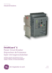
EntelliGuard™ G Trip Unit Type GT-H
User Guide
Bedienungsanleitung für Auslöseeinheit Typ GT-H
Instrukcja obsługi wyzwalaczy GT-H
GE imagination at work
EntelliGuard G
INTRO
BREAKER
TRIP UNIT
Achtung! Wichtige Forderungen!
Uwaga! Ważne zalecenia!
WARNING
Caution! Important Requirements!
CONTENT
HINTS
WARNING
During operation the device described
in this manual is connected to high and
potentially dangerous voltages.
When the circuit breaker is switching
high currents, especially short-circuit
currents, hot and ionized gas may be
emitted.
Only qualified personnel are allowed to
install, commission, maintain or modify
this device in accordance with relevant
safety requirements.
The Circuit Breaker must be equipped
with the appropriate covers and/or be
installed in a suitable enclosure or panel
taking the required safety clearances
into account.
Non Compliance with these
requirements could result in damage to
property and/or severe injury to
personnel.
WARNUNG
Während des Betriebes ist das in
diesem Handbuch beschriebene Gerät
an hohe, potenziell gefährliche
Spannungen angeschlossen.
Aparaty opisane w tej instrukcji podczas
eksploatacji są podłączone do
wysokich, potencjalnie niebezpiecznych
napięć.
Aus Leistungsschaltern können zudem
beim Ausschalten hoher Ströme,
besonders bei Kurzschlüssen, heiße und
ionisierte Gase austreten.
Na skutek rozłączania znacznych
prądów, zwłaszcza prądów
zwarciowych może dochodzić do emisji
gorących i zjonizowanych gazów.
Montage, Inbetriebnahme, Wartung,
Änderung und Nachrüstung dieser
Geräte dürfen deshalb nur von
qualifiziertem Fachpersonal unter
Befolgung der einschlägigen
Sicherheitsvorschriften ausgeführt
werden.
Instalację, uruchomienie, konserwację i
modyfikację aparatów może
wykonywać tylko odpowiednio
przeszkolony personel, zgodnie z
wymogami bezpieczeństwa.
Leistungsschalter müssen während
ihres Betriebes mit dazugehörigen
Abdeckungen versehen sein und / oder
in Gehäusen oder Schaltschränken
unter Berücksichtigung der
Sicherheitsabstände eingebaut sein.
Die Nichtbeachtung dieser Erfordernisse
kann hohe Sachschäden und / oder
schwere Körperverletzungen zur Folge
haben.
Read this manual and please retain for
future use.
1-00
OSTRZEŻENIE
Lesen Sie bitte diese Betriebsanweisung
und bewahren Sie sie bitte griffbereit auf.
Wyłącznik należy zaopatrzyć w
odpowiednie osłony i/lub zainstalować
w obudowie lub rozdzielnicy, z
zastosowaniem odpowiednich
odstępów izolacyjnych.
Nieprzestrzeganie powyższych zasad
może doprowadzić do strat
materialnych i/lub poważnych obrażeń
personelu.
Prosimy o dokładne przeczytanie instrukcji
i zachowanie jej na przyszłość.
EntelliGuard G
1.0 GENERAL INFORMATION
1.0 ALLGEMEINE INFORMATION
1.0 INFORMACJE OGÓLNE
Installation, Operation and Maintenance Manual
Installations-, Betriebs- und WartungsHandbuch
Instrukcja instalacji, obsługi i konserwacji
EntelliGuard G Power Circuit Breaker
EntelliGuard G Leistungsschalter
Wyłączniki EntelliGuard G
HAZARD CATEGORIES
The following important highlighted information
appears throughout this document refers to
potential hazards or to call attention to
information that clarifies a procedure.
Carefully read all instructions and become
familiar with the devices before trying to install,
operate, service or maintain this equipment.
GEFÄHRDUNGSKATEGORIEN
Die folgenden wichtigen, hervorgehoben
Informationen in diesem Dokument warnen vor
möglichen Gefahren oder machen auf
besondere Verfahrenweisen aufmerksam.
Lesen Sie alle Anweisungen aufmerksam durch
und machen Sie sich mit dem Gerät vertraut,
bevor Sie versuchen es zu installieren, zu
betreiben oder Service- und Wartungsarbeiten
an dieser Ausrüstung vorzunehmen.
RODZAJE ZAGROŻEŃ
Ważne informacje, w tym ostrzeżenia o
zagrożeniach i wyjaśnienia zasad obsługi są
zaznaczone kolorową i/lub pogrubioną czcionką.
Przed rozpoczęciem instalacji, użytkowania i
konserwacji należy dokładnie przeczytać całą
instrukcję i zapoznać się z urządzeniem.
1.0
HINTS
INTRO
DANGER | GEFAHR | NIEBEZPIECZEŃSTWO
Indicates a hazardous situation which, if not
avoided, could result in death or serious injury.
CAUTION: Failure to comply with these
instructions may result in product damage.
Zeigt an, dass eine vermeidbare, gefährliche
Situation entstehen kann, die zum Tod oder zu
schweren Verletzungen führen kann.
Oznacza poważne niebezpieczeństwo,
niewłaściwe postępowanie grozi poważnymi
obrażeniami lub śmiercią.
VORSICHT: Die Nichteinhaltung dieser
Anweisungen kann zu Schäden am Produkt
führen.
HINWEIS: Zeigt wichtige Informationen zur
Hilfe und Klarstellung der Angaben.
UWAGA: Postępowanie niezgodne z
zaleceniami oznaczonymi w ten sposób może
doprowadzić do uszkodzenia urządzenia.
WAŻNE: Oznacza ważną informację
ułatwiającą wykonanie danej czynności.
Zalecane jest zachowanie jej na przyszłość.
TRADEMARKS
EntelliGuard G
EntelliGuard TU
SCHUTZMARKEN
EntelliGuard G
EntelliGuard TU
ZNAKI HANDLOWE
EntelliGuard G
EntelliGuard TU
WARRANTY
This document is based on information available
at the time of its publication.
While efforts have been made to ensure
accuracy, the information contained herein does
not cover all details or variations in hardware
and software, nor does it provide for every
possible contingency in connection with
installation, operation, and maintenance.
Features may be described herein that are not
present in all hardware and software systems.
GARANTIE
Dieses Dokument basiert auf zum Zeitpunkt der
Veröffentlichung verfügbaren Informationen.
Es wurden alle Anstrengungen zur
Vollständigkeit des Handbuchs unternommen,
trotzdem kann die hierin enthaltene Information
sich nicht auf alle Details oder Variationen in
Hard- und Software oder auf alle im
Zusammenhang mit Installation, Betrieb und
Wartung auftretenden Möglichkeiten beziehen.
Außerdem können hier Funktionen beschrieben
sein, die nicht in dem vorliegenden Hard- oder
Software-System vorhanden sind.
GWARANCJA
Niniejszy dokument został opracowany na
podstawie informacji aktualnych w czasie
przygotowania do publikacji.
Pomimo dołożenia wszelkich starań, aby
publikowane dane były możliwie dokładne i
szczegółowe - nie możemy zagwarantować że
obejmują one wszystkie szczegóły lub możliwe
wersje urządzeń lub oprogramowania oraz że
zapewniają zgodność pod względem instalacji,
obsługi i konserwacji.
Możliwe jest, że cechy opisane tutaj mogą nie
występować w urządzeniach lub
oprogramowaniu.
GE Electrical Distribution & Control assumes no
obligation of notice to holders of this document
with respect to changes subsequently made.
GE Electrical Distribution & Control übernimmt
keine Verpflichtung zur Mitteilung an die Inhaber
dieses Dokuments in Bezug auf Veränderungen.
GE Electrical Distribution & Control makes no
representation or warranty, expressed, implied,
or statutory, with respect to, and assumes no
responsibility for the accuracy, completeness,
sufficiency, or usefulness of the information
contained herein.
GE Electrical Distribution & Control macht keine
Zusicherungen oder Garantien und übernimmt
keine Verantwortung für die Richtigkeit,
Vollständigkeit oder Nützlichkeit der hierin
enthaltenen Informationen.
NOTICE: An aid meant to assist the user in
performing the set task. Please retain for future
use.
No warrantees of merchantability or fitness for
purpose shall apply.
Es gibt keine Gewährleistungen der
Marktgängigkeit oder Eignung für einen
bestimmten Zweck.
Contact your local sales office if further
information is required concerning any aspect of
EntelliGuard G circuit breaker operation or
maintenance.
Wenden Sie sich bitte an Ihr Verkaufsbüro vor
Ort, falls Sie weitere Informationen zu Aspekten
des EntelliGuard G-Leistungsschalter in Betrieb
oder Wartung benötigen.
GE Electrical Distribution & Control nie ponosi
odpowiedzialności wobec użytkowników
niniejszego dokumentu za zmiany wprowadzone
po jego publikacji.
GE Electrical Distribution & Control nie
gwarantuje, zarówno bezpośrednio jak i w
sposób dorozumiany lub prawny, a także nie
ponosi odpowiedzialności za dokładność,
kompletność, wystarczalność lub użyteczność
informacji zawartych w niniejszej instrukcji.
Nie mają zastosowania jakiekolwiek gwarancje
cech użytkowych urządzenia lub jego
przydatności do określonego celu.
Dodatkowe informacje dotyczące szczegółów
użytkowania lub konserwacji i serwisu
wyłączników EntelliGuard G można uzyskać w
lokalnym biurze sprzedaży GE.
1-01
INTRO
TRIP UNIT
APPENDIX
Content
Inhaltsverzeichnis
Spis treści
2.0 General Information
2.0 Allgemeine Information
2.0 Informacje ogólne
2.1 Product description
2.1 Produktbeschreibung
2.1 Opis urządzenia
2.2 Operation
2.2 Betrieb
2.2 Obsługa
2.3 LCD Screen Mode
2.3 LCD-Display Einstellungen
2.3 Tryby pracy wyświetlacza LCD
2.4 Curves
2.4 Auslösekurven
2.4 Charakterystyki
2.5 Communication Register
2.5 Kommunikationsregister
2.5 Rejestr komunikacyjny
2.6 Installation
2.6 Montagehinweise
2.6 Instalacja
2.7 Connection Scheme
2.7 Anschlussschema
2.7 Schematy połączeń
SCREEN MODE
OPERATION
PRODUCT
GENERAL
EntelliGuard G
note
.
.
.
.
.
notizen | notatki
.
.
.
.
.
.
.
.
.
.
.
.
.
.
.
.
.
.
.
.
.
.
.
.
.
.
.
.
.
.
.
.
.
.
.
.
.
.
.
.
.
.
.
.
.
.
.
.
.
.
.
.
.
.
.
. . . . .
. . . . .
. . . . .
. . . . .
. . . . .
.
.
.
.
.
.
.
.
.
.
.
.
.
.
.
.
.
.
.
.
.
.
.
.
.
.
.
.
.
.
.
.
.
.
.
.
.
.
.
.
.
.
.
.
.
.
.
.
.
.
.
.
.
.
.
.
.
.
.
.
.
.
.
.
.
.
.
.
.
.
.
.
.
.
.
.
CONNECTION INSTALLATION
REGISTER
CURVES
.
.
.
.
.
WARNING | WARNUNG | OSTRZEŻENIE
IMPROPER DISPOSAL
Ensure battery is properly disposed of
according to all applicable regulations.
WARNING:
Only qualified personnel are allowed to install,
operate and maintain all electrical equipment.
Caution
Whilst handling the breaker avoid injury due to
moving parts.
2-00
Unsachgemäße Entsorgung
Stellen Sie bitte sicher, dass die Batterie
ordnungsgemäß, nach den einschlägigen
Bestimmungen entsorgt wird.
UTYLIZACJA
Akumulatory i baterie należy utylizować zgodnie z
obowiązującymi przepisami.
WARNUNG:
OSTRZEŻENIE:
Instalacja, obsługa i konserwacja urządzeń
elektrycznych może być wykonywana tylko przez
wykwalifikowanych specjalistów.
Uwaga
Przy przenoszeniu wyłącznika zwracać uwagę na
części ruchome, aby uniknąć obrażeń.
Nur qualifiziertes Personal darf die Installation, den
Betrieb und die Wartung der elektrischen Geräte
vornehmen.
Hinweis
Vermeiden Sie das Verletzungsrisiko durch
bewegliche Teile während der Handhabung des
Schalters.
EntelliGuard G
2.0 Trip unit
2.0 Auslöseeinheit
2.0 Wyzwalacz nadprądowy
GENERAL INFORMATION
Allgemeine Informationen
INFORMACJE OGÓLNE
2.0
GENERAL
TRIP UNIT
DANGER | GEFAHR | NIEBEZPIECZEŃSTWO
Wyłącznik powinien być otwarty (przez
wyzwolenie), wskaźnik stanu powinien wskazywać
OFF (WYŁ.), sprężyny mechanizmu napędowego
powinny być całkowicie rozluźnione.
Please ensure that the breaker is placed in
tripped position, that the operation indicator
shows OFF and that the mechanisms springs
are fully discharged.
Stellen Sie sicher, das sich der Leistungsschalter
in der Ausgelöst-Stellung befindet, AUS
angezeigt wird und die Antriebsfeder
vollständig entspannt ist.
INTRODUCTION
Einführung
WPROWADZENIE
The EntelliGuard Trip Unit is an electronic device
that interfaces with a circuit breaker. It monitors
the breaker phase currents, neutral current
and/or voltage and trips the breaker in the event
of an over-current or voltage related condition.
Die EntelliGuard Auslöseeinheit ist ein
elektronisches Gerät, das mit dem
Leistungsschalter kommuniziert. Sie überwacht
die Leistungsschalter Phasenströme,
Neutralleiterströme und / oder Spannungen und
schaltet den Leistungsschalter im Falle eines
Überstrom- oder relevanten Spannungvorgangs.
Darüber hinaus werden schützende
Relaisfunktionen, erweiterte Mess-, Diagnoseund Kommunikationsfunktionen bereitgestellt.
Die Auslöseeinheit kann vor Ort durch Entfernen
der Abdeckung des Leistungsschalter ausgebaut
werden.
Die Auslöseeinheit ist mit dem Leistungsschalter
über einen Mitnehmerhebel mechanisch
verbunden, um die elektromechanische
Auslösefunktion einleiten zu können.
Ein Eingabebereich auf der Vorderseite dient zur
Anpassung der Auslöseeinheiten-Parameter.
Kurzworte und Abkürzungen
Die folgenden Abkürzungen und Kurzworte aus
Tab. 2.1, werden in diesem Handbuch
verwendet.
Wyzwalacz nadprądowy jest urządzeniem
elektronicznym współpracującym z
wyłącznikiem. Wyzwalacz monitoruje prądy w
biegunach fazowych, biegunie neutralnym oraz
opcjonalnie napięcie, a w przypadku
nadmiernych wartości prądów lub
niewłaściwych wartości napięcia powoduje
otwarcie (wyzwolenie) wyłącznika. Wyzwalacz
może również posiadać funkcje ochronne
sterujące, funkcje pomiarowe, diagnostyczne i
komunikacyjne. Wyzwalacz nadprądowy może
być wyjęty z wyłącznika np. w celu wymiany w
miejscu eksploatacji po uprzednim odłączeniu
napięcia i zdjęciu płyty czołowej wyłącznika.
Wyzwalacz jest również połączony z
mechanizmem napędowym wyłącznika,
powodując elektromechaniczne wyzwalanie
(otwieranie).
Na płycie czołowej znajduje się panel obsługowy
służący do wprowadzania parametrów pracy
wyzwalacza.
SYMBOLE I NAZWY SKRÓTOWE
W tabeli 2.1 przedstawione są symbole i skróty
używane w tej instrukcji.
It also can provide protective relay functions,
advanced metering, diagnostic features, and
communications. The Trip Unit can be removed
or replaced in the field by de-energizing and
removing the cover of the circuit breaker.
The Trip Unit also connects with the circuit
breaker flux shifter to provide the
electromechanical tripping function.
A user interface is provided on the front panel to
allow adjustment of the Trip Unit’s parameters.
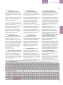
ABBREVIATIONS AND ACRONYMS
The abbreviations and acronyms in Table 2.1
used throughout this manual.
Table 2.1
Denomination / Description
Tab. 2.1
Kürzel / Beschreibung
Tabela 2.1
Oznaczenie / Opis
GF
HSIOC
Groundfault
Hi set Instantaneous protection
GF
HSIOC
Erdschluss
High-Kurzschlussstromschnellauslöser
GF
HSIOC
I2t
I²t
'Slope' setting on ST or GF device
I²t
'Anstieg' für ST- oder GF Schutz
Ie
Ig
Ie
Ig
Ii
Primary Current setting
Ground, or Earth fault Current setting
Instantaneous Short circuit Current
setting
Current rating of Breaker
LT or overload Current setting
ST or Timed Short circuit Current setting
Ie
Ig
Ii
Stromeinstellung
Erd, oder Erdschlussfehler Einstellung
Kurzschlussschnellauslösung Einstellung
In
Ir
Ist
Bemessungsstrom Leistungsschalter
Langzeit oder Überlastschutzeinstellung
ST oder zeitliche
Kurzschlussstromeinstellung
Langzeit oder Überlastschutz
LT oder Überlast-Verzögerungsbereich
Einschaltstromauslöser
Reduzierte Kurzschlussschnellauslösung
Kurzzeit oder zeitliche
Kurzschlussstromeinstellung
ST oder Kurzschluss-Verzögerungsbereich
Vielfaches vom install. Wandlerstrom (In
IEC EntelliGuard Typ = In)
Vielfaches vom Schalterwert Ie
In
Ir
Ist
LT
LTDB
MCR
RELT
ST
STDB
x CT
Long Time or Overload protection
LT or overload time delay band
Making Current Release
Reduced Instantaneous
Short Time or Timed Short circuit
Current setting
ST or short circuit time delay band
LT
LTDB
MCR
RELT
ST
STDB
x CT
Multiple of installed sensor rating (In
IEC EntelliGuard types =In)
x Ie
x Ie
Multiple of Primary Breaker setting Ie
x In
x In
Multiple of Breaker Current rating
x LT
x LT
Multiple of LT or overload Current setting
Ii
In
Ir
Ist
LT
LTDB
MCR
RELT
ST
STDB
x CT
Vielfaches vom LeistungsschalterBemessungsstrom
Vielfaches von LT oder
Überlaststromeinstellung
x Ie
x In
x LT
Zabezpieczenie ziemnozwarciowe
Zabezpieczenie wysokozwarciowe
Ustawienie 'nachylenia' charakterystyki
zabezpieczenia ST lub GF
Podstawowa nastawa prądowa
Nastawa prądowa zabezpieczenia
ziemnozwarciowego
Nastawa prądowa zabezpieczenia
zwarciowego bezzwłocznego
Prąd znamionowy wyłącznika
Nastawa prądowa zabezpieczenia
przeciążeniowego lub długozwłocznego LT
Nastawa prądowa zabezpieczenia
zwarciowego krótkozwłocznego ST
Zabezpieczenie długozwłoczne lub
przeciążeniowe
Zwłoka czasowa zabezpieczenia
długozwłocznego LT lub
przeciążeniowego
Zabezpieczenie przed załączeniem na
zwarcie
Zabezpieczenie zwarciowe bezzwłoczne z
obniżonymi progami zadziałania
Nastawa prądowa zabezpieczenia
zwarciowego krótkozwłocznego
Zwłoka czasowa zabezpieczenia
zwarciowego krótkozwłocznego
Krotność prądu znamionowego
przekładnika prądowego (w wersjach
EntelliGuard wg IEC =In)
Krotność podstawowej nastawy prądowej Ie
Krotność prądu znamionowego wyłącznika
Krotność nastawy przeciążeniowej lub
długozwłocznej
2-01
CONNECTION INSTALLATION
REGISTER
CURVES
SCREEN MODE
OPERATION
PRODUCT
GENERAL
EntelliGuard G
2-02
INTRO
TRIP UNIT
APPENDIX
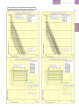
2.1 Product description
2.1 Produktbeschreibung
2.1 Opis wyzwalacza
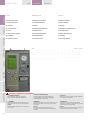
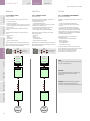
2.1.1 Appearance
The Trip Unit includes a graphical LCD. The front
panel being similar to that depicted in Figure
2.1. Normally the device is set to the English
language, optionally French, German, Spanish or
Chinese can be selected.
2.1.1 Aussehen
Die Auslöseeinheit besitzt ein grafisches LCDDisplay. Die Frontplatte sieht ähnlich der
nachfolgenden Abb. 2.1 aus. Normalerweise ist
das Gerät auf die englische Sprache eingestellt,
wahlweise kann Französisch, Deutsch, Spanisch
oder Chinesisch gewählt werden.
2.1.1 Wygląd zewnętrzny
Wyzwalacz posiada graficzny wyświetlacz
ciekłokrystaliczny (LCD). Panel obsługowy jest
przedstawiony na Fot. 2.1. Zwykle urządzenie jest
ustawione na pracę w jęz. angielskim, opcjonalnie
można wybrać język francuski, niemiecki, hiszpański
lub chiński.
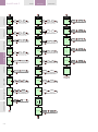
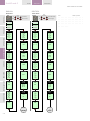
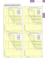
2.1.2 LCD ACCESS
The trip unit has five function keys as shown in
Figure 2.2. Any key, when pressed, powers up
the LCD.
All SETUP, STATUS, METER and EVENTS
information is accessed through these five keys.
2.1.2 LCD-Beschreibung
Die Auslöseeinheit verfügt über fünf
Funktionstasten, wie in Abb. 2.2 dargestellt. Wird
eine beliebige Taste gedrückt, so geht die LCDAnzeige in Betrieb. Auf alle SETUP-, ZÄHLER-,
ZUSTAND und VORFALL-Informationen wird
über diese fünf Tasten zugegriffen.
-- UP: Blättern nach oben oder Werterhöhung
-- DOWN: Nach unten oder Wertverringerung
-- RIGHT: Nächste Funktion oder nächste Seite
-- LEFT: Vorherige Funktion oder zurück zur
vorherigen Seite
-- ENTER: Speichern oder in den Speicher setzen
-- UP: Scroll up or increment value
-- DOWN: Scroll down or decrement value
-- RIGHT: Next function or next page
-- LEFT: Previous function or previous page
-- ENTER: Save or set in to memory
2.1.3 Electrical Requirements
None: Plug in installation. Done on de-energized
units.
2.1.3 Elektrische Anforderungen
Keine: Plug-in Installation. Durchführbar mit
ausgeschalteten Geräten.
2.1.4 Equipment Interfaces
EntelliGuard G Circuit Breakers.
2.1.4 Ausrüstungsschnittstellen
EntelliGuard G Leistungsschalter.
Trip units, for the most part, do not require direct
connections to the equipment. All wiring is
intended to connect to the circuit breaker or
cassette.
Auslöseeinheiten benötigen zum größten Teil
keine direkte Leiterverbindung zum Schalter. Alle
Leitungen sind Verbindungen mit dem
Leistungsschalter oder Einschubträger.
Connections that are required for other
equipment are the optional zone-selective
interlock, relay input and output and the neutral
sensor, which uses specifically dedicated
connection points on the breaker secondary
connection terminals.
Verbindungen sind erforderlich für andere
Ausrüstungen, wie die optionale
Zonenselektivität (ZSI), Relais Ein- und Ausgabe
und dem Neutralwandler, die zu speziellen
Anschlüssen an den Hilfstrennblöcken geführt
werden.
Zone-selective interlocking coordinates breakers
so that the downstream breaker is allowed the
first opportunity to clear a fault or overload
event. The EntelliGuard G zone-selective
interlocking device reacts to ground faults,
_short-time and instantaneous pickups.
Zonenselektivität (ZSI) koordiniert die
Leistungsschalter in der Weise, dass der
nachgeschaltete Schalter die erste Gelegenheit
zur Fehler- oder Überlasterkennung bekommt.
Der EntelliGuard G ZSI-Schutz reagiert auf
Erdschluss, Normal- und KurzzeitKurzschlussereignisse.
Fig. 2.1
LCD screen
Battery Compartment
KEY pad
AUTO/MAN reset choice
Full Range Rating Plug
Abb. 2.1
LCD-Display
Batteriefach
Einstelltasten
AUTO/HAND Auswahl
Stromeinstellmodul
2.1.2 OBSŁUGA WYŚWIETLACZA LCD
Wyzwalacz posiada pięć przycisków funkcyjnych
widocznych na Fot. 2.2. Wciśnięcie dowolnego
przycisku powoduje włączenie zasilania
wyświetlacza. Wszystkie opcje: SETUP
(USTAWIENIA), STATUS (STAN), METER (POMIARY)
oraz EVENTS (ZDARZENIA) są włączane przyciskami
funkcyjnymi.
-- UP (W GÓRĘ): Przejście w górę lub zwiększanie
wartości.
-- DOWN (W DÓŁ): Przejście w dół lub zmniejszanie
wartości.
-- RIGHT (W PRAWO): Następna funkcja lub
następna strona.
-- LEFT (W LEWO): Poprzednia funkcja lub
poprzednia strona.
-- ENTER: Zatwierdzenie lub zapisanie w pamięci.
2.1.3 Wymagania elektryczne
Brak szczególnych wymagań. Wyzwalacz jest
podłączany poprzez złącze wtykowe, przy
odłączonym zasilaniu.
2.1.4 Połączenia z urządzeniami
współpracującymi
Połączenia z wyłącznikami EntelliGuard G.
Wyzwalacze nadprądowe w większości przypadków
nie wymagają bezpośredniego połączenia z
urządzeniami zewnętrznymi. Okablowanie jest
łączone z wyłącznikiem lub podstawą.
Połączeń z innymi urządzeniami wymagają funkcje
opcjonalne: strefowe sterowanie selektywnością,
przekaźnikowe wejścia i wyjścia sterujące, oraz
przekładniki prądowe na torze neutralnym,
wykorzystujące dedykowane punkty
przyłączeniowe na listwie zaciskowej dla obwodów
pomocniczych.
Strefowe sterowanie selektywnością koordynuje
współpracę wyłączników w taki sposób, że
wyłączenie zakłócenia lub przeciążenia jest
wykonywane przez wyłącznik znajdujący się
najbliżej miejsca wystąpienia usterki od strony
Fot. 2.1
Wyświetlacz LCD
Komora baterii / akumulatora
Przyciski obsługowe
Wybór resetu AUTOMATYCZNY / RĘCZNY
Pełnozakresowy moduł nastawczy
Fig 2.2 Key pad
Abb. 2.2 Tasten
Fot. 2.2
Up
Down
Oben
Unten
W górę
W dół
Right (Next)
Left (Previous)
Rechts (Nächster)
Links (Voriger)
W prawo (Następny)
W lewo (Poprzedni)
Enter (Save)
Sichern
Enter (Zapis)
TRIP UNIT
EntelliGuard G
A signal Input (nr.1) can be programmed to allow
for the use of reduced instantaneous (RELT) or
to trip the breaker. A second input (nr. 2) can be
set to ‘OFF’ or programmed to trip the breaker
only.
GT-H-type EntelliGuard G Trip Units have two
output relays that can be assigned to the
following functions:
--· GF Alarm
--· Over-current trip (GF, INST, LT, ST)
--· Reduced Instantaneous (RELT) Active
--· Protective Relays
--· Current Alarm 1
--· Current Alarm 2
--· Health status
The trip units must have the specific option
enabled (as an example protective relay must be
present and enabled in order to allow the
function to actuate the relay).
In addition to the in- and outputs indicated
above the EntelliGuard G type H Trip Units also
can receive inputs from external voltage
conditioners. All Trip Units can be optionally
supplied by a +24 VDC control power supply.
Note: external +24 VDC control power is
required for communication, ZSI and some other
advanced functions. The extended
measurement functionality requires the use of
external voltage conditioners.
All trip unit types have a connection to an
auxiliary switch within the breaker that senses
the breaker’s position.
2.1.4.1 COMMUNICATIONS
External +24 VDC control power is required for
communications. EntelliGuard G Trip Units of the
S, N and H type can optionally support Modbus
communication protocol. In addition,
EntelliGuard G type H Trip Units support Profibus
communication.
Modbus and Profibus connections are made
directly to wiring terminations located at the
circuit breaker top. Internally all Modbus /
Profibus connections are ran through the trip
unit’s top connectors, which mate with a
receptacle on the breaker frame.
2.1.4.1.1 Modbus
The Trip Units are fully compliant with Modbus
Protocol. Full details of the Modbus protocol can
be found in the Modbus Protocol Specification.
Two wire Modbus 485 is supported.
The link Host may operate at a 300, 600, 1200,
2400, 4800, 9600 or 19200-baud rate.
2.1.4.1.2 Profibus
This protocol is integral to specific models of
EntelliGuard G type H Trip Units. ProfiBus DP over
RS485 is supported.
Ein Signal-Eingang (Nr.1) kann so programmiert
werden, dass die Nutzung der reduzierten
Schnellauslösung (RELT) oder den Schalter
auszulösen erlaubt wird. Ein zweiter Eingang
(Nr.2) kann auf ‘AUS’ gesetzt werden oder so
programmiert werden, dass der Schalter nur
auslöst.
GT-H EntelliGuard G Auslöseeinheiten haben
zwei Ausgangsrelais, die folgenden Funktionen
zugeordnet werden können:
-- GF Meldung
-- Überstromauslösung (GF, INST, LT, ST)
-- RELT Schnellauslösung Aktiv
-- Schutzrelais
-- Stromalarm 1
-- Stromalarm 2
-- Auslöserstatusangaben
Die Auslöseeinheiten müssen die spezifischen
Optionen auch aktiviert haben (als Beispiel:
Schutzrelais müssen vorhanden und aktiviert
sein, um für die Schutzfunktion die Betätigung
des Relais zu ermöglichen).
Zusätzlich zu den oben genannten Ein- und
Ausgängen können die EntelliGuard G Typ H
Auslöseeinheiten auch Eingänge von externen
Spannungswandlern erhalten. Alle
Auslöseeinheiten können wahlweise mit einer
+24 VDC Stromversorgung betrieben werden.
Hinweis: externe +24 VDC Steuerspannung ist
für die Kommunikation, ZSI und andere
erweiterte Funktionen erforderlich. Die
erweiterten Messfunktionen erfordern ebenfalls
die Verwendung externer Spannungswandler.
Alle Auslöseeinheitentypen haben eine
Verbindung zu einem Hilfsschalter innerhalb des
Leistungsschalters, der die Schalterstellungen
meldet.
2.1.4.1 KOMMUNIKATION
Eine externe +24 VDC Steuerspannung ist für die
Kommunikation erforderlich. EntelliGuard G
Auslöseeinheiten der S, N-und H-Typen können
optional das Modbus-Kommunikationsprotokoll
unterstützen. Darüber hinaus unterstützt die
EntelliGuard G Typ H-Einheit die ProfibusKommunikation.
Modbus- und Profibus-Verbindungen werden
direkt an den oberen Hilfsanschlüssen am
Leistungsschalter angeschlossen. Intern laufen
alle Modbus- / Profibus-Verbindungen durch die
oberen Anschlüsse der Auslöseeinheit, die mit
den Steckerbuchsen der Schaltergrößen
zusammenpassen.
2.1.4.1.1 Modbus
Die Auslöseeinheiten sind voll kompatibel mit
dem Modbus-Protokoll. Alle Details über das
Modbus-Protokoll finden Sie in der ModbusProtokoll-Spezifikation. Zwei-Draht Modbus 485
wird unterstützt.
Der Hostlink arbeitet mit einer 300, 600, 1200,
2400, 4800, 9600 oder 19200 Baudrate.
2.1.4.1.2 Profibus
Dieses Protokoll ist gibt es nur für die
EntelliGuard G Typ H-Auslöseeinheit. Profibus DP
über RS485 wird unterstützt.
zasilania. Strefowe sterowanie selektywnością
dla zabezpieczenia ziemnozwarciowego
EntelliGuard G reaguje na wartości zwarć
doziemnych z opóźnieniem lub bezzwłocznie.
Wejście sygnałowe (nr 1) może być
programowo ustawione na włączenie
obniżonych nastaw zabezpieczenia
zwarciowego (RELT) lub wyzwolenie (otwarcie)
wyłącznika. Drugie wejście (nr 2) może być
wyłączone (OFF) lub zaprogramowane tylko do
otwierania (wyzwalania) wyłącznika.
Wyzwalacze GT-H EntelliGuard G posiadają dwa
przekaźniki wyjściowe, które można przypisać
do następujących funkcji:
PRODUCT
2.1
--· Alarm ziemnozwarciowy (GF)
--· Wyzwolenie (otwarcie) nadprądowe (GF,
INST, LT, ST)
--· Obniżone zabezpieczenie zwarciowe
bezzwłoczne (RELT) Aktywne
--· Przekaźniki ochronne
--· Alarm prądowy 1
--· Alarm prądowy 2
--· Sygnalizacja prawidłowego działania
Określona opcja musi być włączona w
wyzwalaczu nadprądowym (przykładowo: aby
funkcja mogła sterować przekaźnikiem
ochronnym przekaźnik ten musi być
zainstalowany i włączony).
Ponadto, oprócz wejść i wyjść wspomnianych
wyżej, wyzwalacze EntelliGuard G w wersji H
posiadają wejścia do których można
doprowadzić napięcia z zewnętrznych
przetworników napięcia. Wszystkie wyzwalacze
nadprądowe mogą być opcjonalnie zasilane
napięciem +24V DC.
Uwaga: napięcie zewnętrzne +24V DC jest
konieczne do zasilania modułu
komunikacyjnego, ZSI i niektórych
zaawansowanych funkcji. Funkcje pomiarowe
wymagają zastosowania zewnętrznych
przetworników napięcia.
Wszystkie wyzwalacze nadprądowe są
połączone ze stykiem pomocniczym wyłącznika,
sygnalizującym stan wyłącznika.
2.1.4.1 MODUŁ KOMUNIKACYJNY
Zastosowanie modułu komunikacyjnego
wymaga zewnętrznego zasilania napięciem
+24V DC. Wersje S, N i H wyzwalaczy
EntelliGuard G mogą opcjonalnie obsługiwać
protokół komunikacyjny Modbus. Dodatkowo
wersja H wyzwalacza obsługuje protokół
Profibus.
Magistrale Modbus i Profibus są podłączane
bezpośrednio do zacisków przyłączeniowych w
górnej części wyłącznika. Wewnątrz wszystkie
połączenia Modbus/Profibus są prowadzone
poprzez górne złącza wyzwalacza, łączące się z
gniazdem umieszczonym w ramie wyłącznika.
2.1.4.1.1 Modbus
Wyzwalacze są w pełni zgodne z protokołem
Modbus. Szczegółowe dane protokołu Modbus
można znaleźć w jego specyfikacji technicznej.
Możliwa jest współpraca z dwuprzewodową
magistralą Modbus 485.
Jednostka nadrzędna może pracować z
prędkościami 300, 600, 1200, 2400, 4800, 9600
lub 19200 [baud].
2.1.4.1.2 Profibus
Obsługa tego protokołu jest zastosowana w
wersji H wyzwalacza nadprądowego
EntelliGuard G. Możliwa jest współpraca z
magistralą ProfiBus DP poprzez złącze RS485.
2-03
CONNECTION INSTALLATION
REGISTER
CURVES
SCREEN MODE
OPERATION
PRODUCT
GENERAL
EntelliGuard G
INTRO
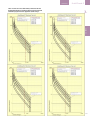
2.1.5 OVER CURRENT PROTECTION functions
The EntelliGuard G Trip Units can provide the
following over current protections:
-- Long Time (Protection against Overload
currents) LT
-- Short Time (Time delayed Protection against
Short circuit currents) ST
-- Instantaneous
(Protection against Short circuit currents) I
-- Reduce Let Through Energy Instantaneous
(Protection against Short circuit currents) RELT
-- Ground Fault Internal Summation
(Optional Protection against Ground Fault
currents) GFsum
-- Ground Fault CT External Summation
(Optional Protection against Ground Fault
currents) GFct
-- Hi level Instantaneous Override (Protection
against High Short circuit currents) HSIOC
-- Making Current Release
(Protection
against closure on a fault) MCR
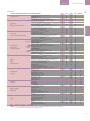
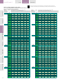
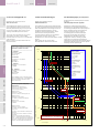
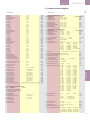
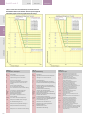
A full overview of the installed overcurrent
protection devices and other optional features
per Trip Unit version is indicated in table 2.2.
2.1.6 Remark on Manual scope
This user manual describes the installation,
connection, maintenance and use of the
EntelliGuard Electronic Trip Units type GT-H.
The functionality of the GT-E, GT-S and
GT-N type is described in a separate
manual.
2.1.7 Manual or Automatic reset function
The breaker reset mode can be chosen by a
selector switch on the Trip Unit front as
indicated in figure 2.3. There are 2 possible
positions or configurations .
1) manual
In this configuration the assembly in the trip unit
interlocks with a mechanical lockout
functionality of the circuit breaker. When the
circuit breaker trips a mechanical interlock
changes state.
This Interlock drives a assembly in the trip unit
forward so that the depicted button “pops” out
from the front of the trip unit. This device also
operates an optional Bell Alarm contact
mounted in the circuit breaker.
In order to re-close the breaker; the mechanical
interlock must be reset by depressing the button
on the front of the trip unit. This also resets the
Bell Alarm contact in the circuit breaker, if
present.
2) auto
In this configuration the assembly in the trip unit
is mechanically restrained so that the depicted
button does not “pop out” from the front of the
trip unit. The optional Bell Alarm contact in the
circuit breaker does not change state.
Fig. 2.3 Selector switch
Abb. 2.3 Auswahlschalter
Fot. 2.3 Przełącznik
2-04
TRIP UNIT
APPENDIX
2.1.5 Überstrom-Schutzfunktionen
Die EntelliGuard G Auslöseeinheiten unterstützen
die folgenden Überstromschutz-Funktionen:
-- Langzeitschutz (Schutz gegen
Überlastströme) LT
-- Kurzzeitschutz (Zeitverzögerter Schutz gegen
Kurzschlussströme) ST
-- Schnellauslösung (Schutz gegen
Kurzschlussströme) I
-- RELT-Schnellauslösung (Schutz gegen
Kurzschlussströme RELT)
-- Erdschluss interne Summierung (Optionaler
Schutz gegen Erdschluss-Ströme) GFsum
-- Erdschluss CT externe Summierung
(Optionaler Schutz gegen Erdschlussströme)
GFct
-- High-Kurzschlussstromschnellauslöser
(HSIOC)
(Schutz gegen hohe Kurzschlussströme)
-- Einschaltstromauslöser (Schutz gegen die
Schließung auf einen Fehler) MCR
Eine vollständige Übersicht des installierten
Überstromschutzes und andere optionale
Funktionen pro Auslöseeinheitenversion siehe
Tab. 2.2.
2.1.5 ZABEZPIECZENIA NADPRĄDOWE
Wyzwalacze nadprądowe EntelliGuard G mogą
posiadać następujące zabezpieczenia
nadprądowe:
-- Długozwłoczne LT (ochrona przed
przeciążeniami)
-- Krótkozwłoczne ST (ochrona zwłoczna przed
prądami zwarciowymi)
-- Bezzwłoczne I (Ochrona przed prądami
zwarciowymi)
-- Bezzwłoczne o obniżonych progach działania
- RELT (Ochrona przed prądami zwarciowymi)
-- Ziemnozwarciowe wewnętrzne sumujące
(różnicowe) GFsum (opcjonalna ochrona przed
zwarciami doziemnymi)
-- Ziemnozwarciowe zewnętrzne sumujące
(różnicowe) GFct, z zewnętrznym
przekładnikiem prądowym (opcjonalna ochrona
przed zwarciami doziemnymi)
-- Wysokozwarciowe bezzwłoczne HSIOC
(ochrona przed dużymi prądami zwarciowymi)
-- Zabezpieczenie przed załączeniem na
zwarcie - MCR
Pełny przegląd zabezpieczeń nadprądowych i
pozostałych opcjonalnych funkcji w
poszczególnych wersjach wyzwalaczy jest
zamieszczony w tabeli 2.2.
2.1.6 Zakres instrukcji
2.1.6 Handbuchanwendung
Dieses Handbuch beschreibt die Installation,
Anschluss, Wartung und Nutzung nur für
EntelliGuard Elektronik-Auslösereinheiten Typ
GT-H.
Die Funktionalität der GT-E, GT-S und
GT-N Typen ist in einem separaten
Handbuch beschrieben.
2.1.7 Manuelle oder Automatische ResetFunktion
Der Leistungsschalter-Reset-Modus kann mit
einem Wahlschalter auf der Frontseite der
Auslöseeinheit, wie in Abb. 2.3 gezeigt, bestimmt
werden. Es gibt 2 mögliche Stellungen oder
Konfigurationen.
1) Manuell (Hand)
In dieser Konfiguration verriegeln die
Auslöseeinheiten mit einer mechanischen
Sperrfunktion des Leistungsschalters. Wenn der
Leistungsschalter auslöst ändert eine
mechanische Verriegelung ihren Zustand.
Diese Verriegelung treibt eine Mechanik in der
Auslöseeinheit an, so dass der abgebildete
Knopf aus der Vorderseite des Auslöseeinheit
hervorspringt. Dieses Gerät betätigt außerdem
einen im Leistungsschalter montierten,
optionalen Störmeldeschalter.
Zur Wiederherstellung des Schaltzustands, muss
die mechanische Verriegelung durch Drücken
der Taste an der Vorderseite der Auslöseeinheit
zurückgesetzt werden. Dies setzt auch den
Störmeldeschalter im Leistungsschalter, falls
vorhanden, zurück.
2) Automatik
In dieser Konfiguration verhält sich die
Auslöseeinheit mechanisch so, dass die
abgebildete Taste nicht hervorspringt. Der
optionale Störmeldeschalter im
Leistungsschalter verändert nicht seinen
Zustand. Der Leistungsschalter kann wieder
geschlossen werden (entweder manuell oder mit
einem Abrufmagneten), ohne das Zurücksetzen
Niniejsza instrukcja zawiera opis instalacji,
podłączenia, konserwacji i obsługi wyzwalaczy
GT-H.
Funkcje wyzwalaczy GT-E, GT-S i
GT-N są opisane w odrębnych
instrukcjach.
2.1.7 Ręczny lub automatyczny reset
(odblokowanie)
Sposób resetowania (odblokowania) wyłącznika
może być wybrany przełącznikiem na panelu
frontowym wyzwalacza, przedstawionym na
Fot. 2.3. Możliwe są dwa ustawienia.
1) Reset ręczny
W tym ustawieniu mechanizm wyzwalacza
nadprądowego jest sprzężony z mechanizmem
blokującym wyłącznika. Gdy wyłącznik zostaje
wyzwolony (otwarty przez wyzwalacz) blokada
mechaniczna zmienia swój stan. Blokada ta
przesuwa do przodu podzespół blokujący
wyzwalacza nadprądowego, wskutek czego
przedstawiony przycisk 'wystaje' z płyty czołowej
wyzwalacza. Mechanizm włącza również
opcjonalny łącznik alarmowy wbudowany w
wyłączniku.
Aby zamknąć wyłącznik konieczne jest
wyłączenie (reset) blokady mechanicznej
poprzez wciśnięcie przycisku na panelu
czołowym wyzwalacza. Następuje wtedy
również zmiana położenia łącznika alarmowego,
jeśli jest on wbudowany w wyłączniku.
2) Reset automatyczny
W tym ustawieniu działanie mechanizmu
wyzwalacza nadprądowego jest mechanicznie
zredukowane w taki sposób, że nie następuje
wysunięcie przycisku z płyty czołowej
wyzwalacza. Opcjonalny łącznik alarmowy w
wyłączniku nie zmienia swego stanu.
Wyłącznik może być ponownie zamknięty
(ręcznie lub przy pomocy cewki zamykającej) bez
EntelliGuard G
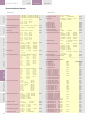
TRIP UNIT
ENGLISH
Setting Interface
Long Time
or
Overload Current Protection
Short Time
Short Circuit Current Protection
Standard
Instantaneous
Short Circuit
Current Protection
Extended
range
Reduced
Ground
or
Earth
Fault Protection
Measurement
package
Protective
Relaying
Data Acquisition
&
Diagnostics
Other
LCD Screen allowing access to 4 distinct Menu's
Touch pad adjustments
Multilingual
Adjustable Manual or Automatic RESET option
6 primary current settings Ie with FULL RANGE Rating Plug
1, 0.975. 0.9625, 0.95 , 0.45 & 0.4 x Breaker rating In
11 secondary current settings Ir
1, 0.95, 0.9. 0,85, 0.8, 0.75, 0.7, 0.65, 0.6, 0.55, 0.5
x Primary setting
Resulting setting Range 0.2 to 1 with 66 set points
22 Thermal Protection (C type) time bands available Ranging from
class 0.5 to 40 (bands at 7.2 x Ir)
2
22 I t Protection (F type {fuse} ) time bands available
Neutral Protection 0-50%-63%-100%
Cooling function and Thermal memory
Setting RANGE from 1.5 to 12 x Ir (LT setting)
Steps of 0.5 (A total of 22 settings)
Possibility to Switch OFF
17 Time delay settings (STDB) ranging from 30 to 940 milliseconds
delay setting result in a 90 to 1000 Milliseconds Clearing time
Clearance times to IEC 40979-1 and IEC 60364
2
3 I t Protection time bands available
Ii Setting RANGE from 2 to 15 x Ie (Primary Setting)
Steps of 0.5 (A total of 28 settings)
Possibility to Switch OFF
Selective Execution
Fixed Instantaneous or HSIOC protection
Ihi Setting RANGE from 2 to 30 x Ie (Primary Setting)
2-15 Steps of 0.5; 15-30x steps of 1 (A total of 43 settings)
Possibility to Switch OFF
Selective Execution
Fixed Instantaneous or HSIOC protection
Ii Setting RANGE from 1.5 to 15 x Ie (Primary Setting)
Steps of 0.5 (A total of 29 settings)
Possibility to Switch OFF
Remote and Local ON and OFF with position indication signal.
(1)
Setting RANGE from 0.1 to 1 x In (Breaker Rating)
Steps of 0.01 (A total of 92 settings)
Possibility to Switch OFF
14 Time delay settings (GFDB) ranging from 50 to 840 milliseconds
delay setting resulting in a 110 to 900 Milliseconds Clearing time
Clearance times to IEC 40979-1 and IEC 60364
2
2 I t Protection time bands available
4
1 Fuse I t Protection time band available
Residual Principle
Source Ground Return Principle
UEF, REF and SEF applications possible
Combinations of UEF, REF and SEF applications possible
Current (L1, L2, L3, N)
Voltage (L1, L2, L3)
Energy (kWh) Total Real
Real Power (L1, L2, L3, total)
Apparent Power (L1, L2, L3, total)
Reactive Power (L1, L2, L3, Total)
Total Power (L1, L2, L3, total)
Power (kW) Peak (total)
Demand Power (kW) (total)
Frequency (L1, L2, L3)
Voltage Unbalance
Under Voltage
Over Voltage
Current Unbalance
Power Reversal
Trip Target (trip reason indication)
Trip Info (Magnitude / Phase)
Waveform capture
Trip Counter
Event Logger (trip events)
Relay based on current level (load shedding)
Good & Bad Health Indicator
Watchdog
Zone Selective Interlock on ST, GF and I
Shunt trip status input (2 inputs)
UVR trip status input (2 inputs)
General Relay Outputs (2 avail)
Communication 2 way
Modbus
Profibus
24V DC Auxiliary Power supply
Text kit with Power support function
Remarks
GT-E
X
X
X
X
GT-S
X
X
X
X
GT-N
X
X
X
X
GT-H
X
X
X
X
X
X
X
X
X
X
X
X
--
X
X
X
X
-
-
-
X
---
X
X
X
X
-
X
X
X
X
-
X
X
X
X
-
X
X
X
X
X
X
X
X
X
X
X
X
X
X
O
O
O
O
O
O
O
X
X
X
X
O
O
X
X
X
X
X
X
X
O
O
O
O
X
O
O
O
O
O
O
O
O
O
X
X
X
X
O
O
O
O
X
X
X
X
X
X
X
O
O
O
O
X
X
X
X
X
O
O
O
O
O
O
O
O
O
X
X
X
X
X
X
X
X
X
X
X
X
X
O
O
O
O
O
X
X
X
X
X
X
X
O
O
O
O
X
X
X
X
X
O
O
O
O
O
O
O
O
O
O
O
O
X
X
X
X
X
X
X
X
X
X
X
X
X
X
X
X
X
X
X
X
X
X
X
O
O
O
O
X
O
O
O
O
2.1
------
PRODUCT
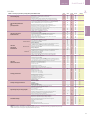
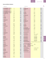
Table 2.2 EntelliGuard GT Electronic Trip Unit Functionality
-----------------------O
------------C
C
C
C
C
C
C
C
-N
N
N
N
N
--N
-----N
---N
N
N
-O
Key
X - Present ; O = Optional , - = Not Possible
Remarks If an N is indicated a 24V auxiliary power supply is required, a C indicates the need of a Power Conditioner
(1) Without a 24V auxiliary power supply, the lowest setting is 0.2.
2-05
EntelliGuard G
INTRO
TRIP UNIT
APPENDIX
Deutsch
Einstellschnittstelle
Langzeit
&
Überlaststromschutz
Kurzzeit
&
Kurzschlussstromschutz
Standard I
KurzschlussschnellAuslösungsschutz
CONNECTION INSTALLATION
REGISTER
CURVES
SCREEN MODE
OPERATION
PRODUCT
GENERAL
Tab. 2.2 EntelliGuard GT Elektronik-Auslöseeinheit: Funktionen
Erweiterter
Bereich HSIOC
Reduziert RELT
Masse- oder Erdschlussschutz
Messdatenerfassung
Schutzumfang
Datenübernahme
&
Diagnose
Sonstiges
LCD-Display erlaubt Zugang zu 4 eindeutigen Menüs
Eingabe über Bedienfeld
Mehrsprachig
Justierbare Manuelle oder Automatik-Rücksetzmöglichkeit
6 Stromeinstellungen Ie mit Stromeinstellmodul
1, 0.975. 0.9625, 0.95 , 0.45 & 0.4 x Schalterwert In
11 Sekundärstromeinstellungen Ir
1, 0.95, 0.9. 0,85, 0.8, 0.75, 0.7, 0.65, 0.6, 0.55, 0.5 x Ie Enstellung
Resultierender Einstellbereich 0,2 bis 1 mit 66 Einstellpunkten
22 I²t Therm. Schutzbereiche (C Typ) verfügbare Bandbreite von
Klasse 0.5 bis 40 (Bereich bis 7.2 Ir)
22 I²t Schutzbereiche (F-Typ Sicherung) sind verfügbar
Neutralleiter-Schutz (50%- 63%- 100%)
Abkühlungsfunktion und Thermisches Gedächtnis (Speicherung)
Einstellbereich von 1,5 bis 12 xIr (LT Einstellung)
Schritte von 0.5 (gesamt 22 Einstellungen)
AUS-Schaltmöglichkeit
17 Zeitverzögerungseinstellungen (STDB) von 30-940 ms
Verzög.zeit ergibt 90-1000ms Ausschaltzeit
Ausschaltzeit nach IEC 409791 und IEC 60364
3 I²t Schutzbereiche sind verfügbar
Ii Einstellbreite von 2 - 15 xIe Einstellung
Schritte von 0.5 (gesamt 28 Einstellungen)
AUS-Schaltmöglichkeit
Selektive Ausführung
Unverstellbarer Schnellauslöser oder HSIOC Schutz
Ihi Einstellbreite von 2 - 30 xIe-Einstellung
2-15 Stufen von 0.5; 15-30 x Stufen von 1 (insgesamt 43 Einstellungen)
AUS-Schaltmöglichkeit
Selektive Ausführung
Unverstellbar Schnellauslöser- oder HSIOC Schutz
Ii Einstellbreite von 1,5 - 15 xIe-Einstellung
Schritte von 0.5 (gesamt 29 Einstellungen)
AUS-Schaltmöglichkeit
Fern- und Vorort EIN und AUS mit Stellungsanzeigemeldung.
Einstellbereich von 0,1 bis 1 xIn (Schalterwert) (1)
Schrittweise 0.01 (gesamt 92 Einstellungen)
AUS-Schaltmöglichkeit
14 Zeitverzögerungseinstellungen (GFDB) von 50-840 ms
Verzögerungseinstellung sich ergebend in 110-900ms Ausschaltzeit
Ausschaltzeit nach IEC 409791 und IEC 60364
2 I²t Schutzbereiche sind verfügbar
1 Sicherung I4t Schutz-Zeitbereich ist verfügbar
Fehlerstromprinzip
'Source Ground Return'-Methode
UEF, REF und SEF Anwendungsmöglichkeiten
Kombination von UEF, REF und SEF Anwendungen möglich
Strom (L1, L2, L3)
Spannung (L1, L2, L3)
Energie (kWh) Total Wirkleistung
Wirkleistung (L1, L2, L3, total)
Scheinleistung (L1, L2, L3, gesamt)
Blindleistung (L1, L2, L3, total)
Gesamtleistung (L1, L2, L3, total)
Leistung (kW) Spitzenwert (total)
Energiebedarf (kW) (gesamt)
Frequenz (L1, L2, L3)
Schieflast Spannung
Unterspannung
Überspannung
Schieflast Strom
Rückspeisung
Auslösezielvorgabe (Auslösegrundanzeige)
Auslöseinformation (Größenordnung / Phase)
Kurvenstromerfassung
Auslösungszähler
Vorfallsregistrierung (Auslösevorfälle)
Lastüberwachung
Gut & Schlechtzustands-Anzeige
Überwachung (Watchdog)
Zonenselektivität (ZSI) auf ST, GF und I
A-Auslöser Zustand Eingang (2 Eingänge)
U-Auslöser Zustand Eingang (2 Eingänge)
Allgemeine Relaisausgänge (2 verfügb.) und Elektronikeingänge (2)
2 Wege-Kommunikation
Modbus
Profibus
24VDC Fremdversorgung
Tester mit Einspeisefunktion
GT-S
X
X
X
X
GT-N
X
X
X
X
GT-H
X
X
X
X
X
X
X
X
X
X
X
X
--
X
X
X
X
-
-
-
X
---
X
X
X
X
-
X
X
X
X
-
X
X
X
X
-
X
X
X
X
X
X
X
X
X
X
X
X
X
X
O
O
O
O
O
O
O
X
X
X
X
O
O
X
X
X
X
X
X
X
O
O
O
O
X
O
O
O
O
O
O
O
O
O
X
X
X
X
O
O
O
O
X
X
X
X
X
X
X
O
O
O
O
X
X
X
X
X
O
O
O
O
O
O
O
O
O
X
X
X
X
X
X
X
X
X
X
X
X
X
O
O
O
O
O
X
X
X
X
X
X
X
O
O
O
O
X
X
X
X
X
O
O
O
O
O
O
O
O
O
O
O
O
X
X
X
X
X
X
X
X
X
X
X
X
X
X
X
X
X
X
X
X
X
X
X
O
O
O
O
X
O
O
O
O
Zeichen : X = Vorhanden; O = Optional; - = Nicht möglich
Hinweis: Wenn ein N angezeigt ist, so wird eine 24V Fremdversorgung benötigt, bei C wird eine Anzeigeverbesserung benötigt.
(1) Ohne 24V Fremdspannungsversorgung, ist 0.2 der niedrigste Einstellwert.
2-06
Bemerkung
GT-E
X
X
X
X
------
-----------------------O
------------C
C
C
C
C
C
C
C
-N
N
N
N
N
--N
-----N
---N
N
N
-O
EntelliGuard G
POLSKA
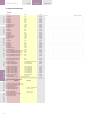
Tabela 2.2 Funkcje wyzwalaczy nadprądowych EntelliGuard GT
Wyświetlacz LCD z dostępem do 4 oddzielnych menu
Wprowadzanie ustawień przez panel dotykowy
Wielojęzyczne menu
Przełączany RESET: Ręczny (Manual) lub Automatyczny (Automatic)
6 podstawowych ustawień prądowych Ie z PEŁNOZAKRESOWYM modułem
nastawczym 1, 0,975, 0,9625, 0,95, 0,45 i 0,4 x Prąd znamionowy In wyłącznika
11 pomocniczych (wtórnych) nastaw prądowych Ir 1, 0,95, 0,9, 0,85, 0,8,
0,75, 0,7, 0,65, 0,6, 0,55, 0,5 x ustawienie podstawowe Ie
Wynikowy zakres nastaw: od 0,2 do 1 z 66 ustawieniami
Dostępne 22 ustawienia czasowe dla ochrony termicznej (typ C).
Zakres od klasy 0,5 do 40 (ustawienia dla 7,2 x Ir)
Panel obsługowy
Ochrona długozwłoczna
lub
przeciążeniowa
Dostępne 22 ustawienia czasowe dla charakterystyk zależnych I2t typu F (bezpiecznikowe)
Ochrona zwarciowa
krótkozwłoczna
Standardowa
Ochrona toru neutralnego: 0-50%-63%-100%
Funkcja chłodzenia i pamięć termiczna
ZAKRES nastaw od 1.5 do 12 x Ir (nastawa LT)
Krok ustawień 0.5 (ogółem 22 ustawień)
Możliwość wyłączenia (OFF)
17 nastaw opóźnień czasowych (STDB) w zakresie od 30 do 940
milisekund, w rezultacie czas wyłączania zwarć w zakresie
od 90 do 1000 milisekund
Czas wyłączania zwarć zgodny z normami IEC 40979-1 i IEC 60364
Dostępne 3 ch-ki czasowe zależne I2t
Ii ZAKRES nastaw od 2 do 15 x Ie (ustawienie podstawowe)
Krok ustawień 0,5 (ogółem 28 ustawień)
Możliwość wyłączenia (OFF)
Wersja selektywna
Zabezpieczenie bezzwłoczne na stałym poziomie lub wysokozwarciowe (HSIOC)
Ihi ZAKRES nastaw od 2 do 30 x Ie (ustawienie podstawowe)
Ochrona
zwarciowa
bezzwłoczna
Zakres 2-15x: w krokach =0,5; zakres 15-30x: w krokach =1 (ogółem 43 nastawy)
Rozszerzona
Zabezpieczenie bezzwłoczne na stałym poziomie lub wysokozwarciowe (HSIOC)
Obniżona
Ochrona
ziemnozwarciowa
Funkcje pomiarowe
Funkcje sterujące ochronne
Rejestracja danych i diagnostyka
Pozostałe funkcje
Możliwość wyłączenia (OFF)
Wersja selektywna
Ii ZAKRES ustawień od 1,5 do 15 x Ie (ustawienie podstawowe)
Kroki 0,5 (ogółem 29 ustawień)
Możliwość wyłączenia (OFF)
Zdalne i lokalne WŁĄCZ i WYŁĄCZ (ON i OFF) z sygnalizacją stanu
ZAKRES nastaw od 0,1 do 1 x In (Prąd znamionowy wyłącznika) (1)
Krok 0,01 (ogółem 92 ustawienia)
Możliwość wyłączenia (OFF)
14 nastaw opóźnień czasowych (GFDB) w zakresie od 50 do 840 milisek.,
w rezultacie zakres regulacji czasu wyłączania od 110 do 900 milisekund
Czasy wyłączania zgodne z normami IEC 40979-1 i IEC 60364
Dostępne 2 ch-ki czasowe zależne I2t
Dostępna 1 ch-ka bezpiecznikowa I4t
Metoda różnicowa
Metoda powrotu do źródła
Możliwe wersje ochrony: UEF, REF i SEF
Możliwe kombinacje (połączenie) wersji UEF, REF i SEF
Prąd (L1, L2, L3, N)
Napięcie (L1, L2, L3)
Energia czynna (kWh), suma
Moc czynna (L1, L2, L3, suma)
Moc pozorna (L1, L2, L3, suma)
Moc bierna (L1, L2, L3, suma)
Moc całkowita (L1, L2, L3, suma)
Moc maksymalna (kW) (suma)
Zapotrzebowanie mocy (kW) (suma)
Częstotliwość (L1, L2, L3)
Asymetria napięć
Obniżenie napięcia
Przepięcia
Asymetria prądów
Odwrotny przepływ mocy
Powód wyzwolenia (wskazanie przyczyny wyzwolenia)
Informacje o wyzwoleniu (wartość / biegun)
Rejestracja przebiegu prądu
Licznik wyzwoleń
Rejestracja zdarzeń (wyzwoleń)
Sterowanie zależne od wartości prądu (zmniejszanie obciążenia)
Sygnalizacja prawidłowego i nieprawidłowego działania
Kontrola realizacji programu (watchdog)
Strefowe sterowanie selektywnością (ZSI) dla funkcji ST, GF oraz I
Wejście stanu wyzwalacza napięciowego (2 wejścia)
Wejście stanu wyzwalacza napięciowego (2 wejścia)
Wyjścia przekaźnikowe ogólnego przeznaczenia (2 wyjścia)
Komunikacja dwukierunkowa
Modbus
Profibus
Zasilacz pomocniczy 24V DC
Tester wyzwalacza z zasilaniem pomocniczym
Uwagi
GT-E
X
X
X
X
GT-S
X
X
X
X
GT-N
X
X
X
X
GT-H
X
X
X
X
X
X
X
X
X
X
X
X
--
X
X
X
X
-
-
-
X
---
X
X
X
X
-
X
X
X
X
-
X
X
X
X
-
X
X
X
X
X
X
X
X
X
X
X
X
X
X
O
O
O
O
O
O
O
X
X
X
X
O
O
X
X
X
X
X
X
X
O
O
O
O
X
O
O
O
O
O
O
O
O
O
X
X
X
X
O
O
O
O
X
X
X
X
X
X
X
O
O
O
O
X
X
X
X
X
O
O
O
O
O
O
O
O
O
X
X
X
X
X
X
X
X
X
X
X
X
X
O
O
O
O
O
X
X
X
X
X
X
X
O
O
O
O
X
X
X
X
X
O
O
O
O
O
O
O
O
O
O
O
O
X
X
X
X
X
X
X
X
X
X
X
X
X
X
X
X
X
X
X
X
X
X
X
O
O
O
O
X
O
O
O
O
2.1
------
--------
PRODUCT
TRIP UNIT
----------------O
------------C
C
C
C
C
C
C
C
-N
N
N
N
N
--N
-----N
---N
N
N
-O
Legenda: X = Tak; O = Opcjonalnie, - = Nie jest możliwe
Uwagi: 'N' wskazuje, że wymagane jest napięcie pomocnicze 24V, 'C' oznacza, że konieczny jest przetwornik pomiarowy
(1) Bez zasilania pomocniczego 24V najniższe ustawienie wynosi 0,2
2-07
CONNECTION INSTALLATION
REGISTER
CURVES
SCREEN MODE
OPERATION
PRODUCT
GENERAL
EntelliGuard G
INTRO
The breaker can be re-closed (Either manually or
using a closing coil) without resetting the button
since it is held in the reset position.
2.1.8 Full Range Rating Plug
Each EntelliGuard Electronic Trip Unit must be
equipped with a separately available Rating Plug
to allow it to function correctly. The Full Range
Rating Plug is plugged into a jack on the trip Unit
Front Face. When this device is not installed the
Trip Unit will revert to it's minimum setting,
Fig. 2.4 Rating plug
Abb. 2.4 Stromeinstellmodul
Fot. 2.4 Moduł nastawczy
which has as value of 16-18% of the breaker
rating In.
Rating plugs can be removed with a Rating Plug
Extractor, Catalogue No. FAR reference code
432861 . (Suitable equivalents are commercially
available as 'integrated circuit (DIP) extractors'.
Grasp the rating plug tabs with the extractor
and pull the plug out.
Be sure to grab the tabs and not the front cover
of the rating plug, or the plug may be damaged.
2.1.9 Power requirements
A small amount of power is necessary to
energize the liquid crystal display (LCD) during
setup, for viewing breaker status and for
metering displays.
The power sources can be one of the following:
– Current flow: Breaker current sensors provide
sufficient power to energize the LCD when at
least 20% of the sensor's ampere rating is
flowing.
--- +24 VDC control power
— Internal battery power: Powers the unit
temporarily when any keypad key is pressed.
Battery power automatically turns off 20 sec
after the last keypad press. The battery power
supply is disabled when any current is sensed
through the current sensors.
- Test kit Catalogue No. GTUTK20 reference
code 407999 has a extra internal battery that
can be used to power the trip unit when internal
battery power is not present. The device also
has a built in 24 VDC control power supply that
can be powered up through a standard mains
connection.
The EntelliGuard G Trip Units require external
+24 VDC control power for communication.
2.1.9.1 Battery
GENERAL BATTERY INFORMATION
The trip unit has a front panel mounted battery.
When the battery is present, the user can view
data on the LCD and read or program the trip
unit via the keypads. The battery allows the user
to display data, change set points and provide
thermal memory.
The battery does not allow normal trip unit
operation; i.e. over current protection, alarms,
relays, etc., are not functional when the trip unit
is powered from the battery. The trip unit will
automatically shut off after 20 sec when battery
TRIP UNIT
APPENDIX
der Taste, da er in der Resetstellung gehalten
wird.
2.1.8 Stromeinstellmodule
Alle EntelliGuard Elektronik Auslöseeinheiten
müssen mit einem separat verfügbaren
Stromeinstellmodul ausgerüstet werden, damit
sie korrekt funktionieren. Das Stromeinstellmodul
wird in eine Vertiefung in der Vorderseite
eingesteckt. Wird dieses Modul nicht installiert,
so wird die Auslöseeinheit auf ihren Mindestwert
innerhalb einer Grenze von 16-18% des
Leistungsschalter Stromes In gesetzt.
Stromeinstellmodule können mit einer
Modulzange entfernt werden, Katalog-Nr FAR
Referenz-Code 432861. (Ähnliche Ausführungen
sind im Handel als 'Integrated circuit (DIP)
extractors' erhältlich.
Umfassen Sie das Strommodul mit der
Modulzange und ziehen Sie das Modul aus dem
Steckplatz heraus. Stellen Sie sicher, dass Sie die
Verriegelungen und nicht die vordere Abdeckung
des Stromeinstellmoduls greifen, weil sonst das
Modul beschädigt werden könnte.
2.1.9 Stromversorgung
Nur eine kleine Leistung ist erforderlich, um die
Energie für das Liquid Crystal Display (LCD)
während der Einstellungen aufzubringen, sowie
für die Anzeige von Schalterstatus und Messung.
Die Stromversorgung kann eine der folgenden
Optionen sein:
-- Stromfluss: Aktuelle LeistungsschalterWandler liefern die notwendige Versorgung für
die LCD-Energie, wenn mindestens 20% des
Wandlerstroms fließt.
--- +24 VDC Steuerspannung
--- Interner Batteriebetrieb: Versorgt die
Einheit vorübergehend, nur wenn eine Taste
gedrückt wird. Die Batterie-Stromversorgung
wird automatisch nach 20 Sek. deaktiviert,
nachdem die letzte Tastenbetätigung
vorgenommen wurde. Die BatterieStromversorgung ist deaktiviert, wenn irgendein
Strom durch die Wandler fließt.
- Der Tester, Katalog-Nr GTUTK20 ReferenzCode 407999, verfügt über eine zusätzliche
interne Batterie und kann verwendet werden,
um die Auslöseeinheit, wenn deren interne
Batteriespannung nicht ausreicht, zu versorgen.
Das Gerät verfügt außerdem über eine
eingebaute 24VDC-Stromversorgung, die über
einen Standard-Netzanschluss aufgeladen
werden kann.
Die EntelliGuard G Auslöseeinheiten erfordern
eine externe +24 VDC Versorgung für die
Kommunikation.
2.1.9.1 Batterie
Allgemeine Batterie-Informationen
Die Auslöseeinheit verfügt über eine im
Frontfenster montierte Batterie. Wenn die
Batterie vorhanden ist, kann der Nutzer Daten
anzuzeigen und lesen, oder über die Tastatur die
Auslöseeinheit programmieren. Die Batterie
ermöglicht es dem Benutzer, Daten anzuzeigen,
sie zu ändern und thermische Grenzwerte zu
konieczności odblokowania przy pomocy
przycisku, ponieważ jest on utrzymywany w
położeniu odblokowanym.
2.1.8 Pełnozakresowy moduł nastawczy
Każdy wyzwalacz nadprądowy wyłączników
EntelliGuard musi być wyposażony w oddzielnie
zamawiany moduł nastawczy umożliwiający
jego prawidłowe działanie. Pełnozakresowy
moduł nastawczy jest podłączany do gniazda w
płycie czołowej wyzwalacza nadprądowego.
Jeśli moduł nie jest podłączony wyzwalacz
pracuje z najniższymi wartościami nastaw na
poziomie 16-18% prądu znamionowego In
wyłącznika.
Moduły nastawcze można odłączyć przy użyciu
specjalnego uchwytu (ekstraktora), nr kat. FAR,
nr ref. 432861 (odpowiedniki są dostępne jako
'ekstraktory układów scalonych').
Aby odłączyć moduł wystarczy chwycić
uchwytem jego klamry i wyciągnąć z gniazda.
Należy przy tym zwrócić uwagę, aby nie chwycić
za obudowę modułu nastawczego, ponieważ
może to doprowadzić do jego uszkodzenia.
2.1.9 Zasilanie wyzwalaczy nadprądowych
Pobór mocy przez wyświetlacz ciekłokrystaliczny
(LCD) podczas wprowadzania ustawień,
przeglądania parametrów pracy oraz funkcji
pomiarowych jest niewielki.
Wyzwalacz może być zasilany z następujących
źródeł:
--- przepływ prądu w torach głównych:
przekładniki prądowe dostarczają wystarczającą
ilość energii do zasilania wyświetlacza, jeśli prąd
w obwodach przekładnika prądowego wynosi
przynajmniej 20% wartości znamionowej.
--- zasilanie pomocnicze +24V DC
--- wewnętrzna bateria / akumulator zasila
wyzwalacz tymczasowo, gdy wciśnięty jest
którykolwiek z przycisków. Zasilanie z baterii /
akumulatora jest wyłączane automatycznie po
20 sekundach od ostatniego wciśnięcia
przycisku. Zasilanie z baterii / akumulatora
zostaje wyłączone, gdy w przekładniku
prądowym zostaje wykryty jakikolwiek przepływ
prądu.
- Tester wyzwalacza (nr kat. GTUTK20, nr ref.
407999) posiada dodatkowy wewnętrzną
baterię / akumulator , używany do zasilania
wyzwalacza gdy brak zasilania z jego
wewnętrznej baterii / akumulatora. Tester jest
również wyposażony w zasilacz 24V DC, zasilany
standardowo z sieci.
Wyzwalacze EntelliGuard G wymagają
zewnętrznego zasilania +24V DC dla modułów
komunikacyjnych.
2.1.9.1 Bateria / Akumulator
INFORMACJE OGÓLNE O BATERII /
AKUMULATORZE
Wyzwalacz nadprądowy posiada baterię
wbudowaną w panel frontowy. Gdy jest
podłączona - użytkownik przy pomocy
przycisków klawiatury i wyświetlacza LCD może
WARNING | WARNUNG | OSTRZEŻENIE
IMPROPER DISPOSAL
Unsachgemäße Entsorgung
Ensure battery is properly disposed of according to Stellen Sie bitte sicher, dass die Batterie
all applicable regulations.
ordnungsgemäß, nach den einschlägigen
Bestimmungen, entsorgt wird.
2-08
UTYLIZACJA
Akumulatory i baterie należy utylizować zgodnie z
przepisami.
TRIP UNIT
EntelliGuard G
powered, this to maximize battery life.
BATTERY FUNCTION
Pressing any key on the face of the trip unit
powers the unit from its internal battery. Battery
power is maintained for 20 sec after the last key
is pressed.
This self-powered mode allows setting up the
trip unit or viewing trip targets when the breaker
is de-energized and external control power is
unavailable.
All normal setup, meter, and status functions can
be performed with battery power.
setzen.
Die Batterie erlaubt keinen normalen
Auslöseeinheiten Betrieb, d.h. Überstromschutz-,
Alarm-, Relaisfunktionen, etc., sind nicht
funktionsfähig, während die Auslöseeinheit von
der Batterie gespeist wird. Die Auslöseeinheit
schaltet sich bei Batteriebetrieb automatisch
nach 20 Sek. zur Maximierung der
Batterielaufzeit aus.
Replacement
Replace the battery if it does not power up the
trip unit when any key is pressed.
Lift the battery cover on the front of the trip unit
to expose the 3.6 V 1/2 AA lithium cell.
Batterie Funktion
Das Drücken einer beliebigen Taste auf der
Frontseite der Auslöseeinheit führt zur
Inbetriebnahme der internen Batterie. Die
Batterieenergie wird für 20 Sekunden nach dem
letzten Tastendruck bereitgestellt.
Dieser Selbstversorgungsmodus erlaubt die
Einstellung der Auslöseeinheit oder das Anzeigen
von Auslösewerten, auch wenn der
Leistungsschalter deaktiviert ist und keine
externe Spannungsversorgung verfügbar ist.
Alle normalen Einrichtungen, Mess- und
Statusfunktionen können mit Batteriebetrieb
durchgeführt werden.
-- A suitable replacement is TADIRAN part
number TLL-5902/S or SANYO part number
CR14250SE which are commonly available from
most electrical stores or industrial distributors.
Bemerkung
Bei Temperaturen über 40°C muss eine beliebige
Taste bis zu 5 Sekunden gehalten werden, damit
die Auslöseeinheit einschaltet.
Remark
For temperatures above 40°C, any key may have
to be held down for up to 5 sec for the trip unit
to be powered.
Austausch
Ersetzen Sie die Batterie, wenn ein Tastendruck
nicht zum Einschalten der Auslöseeinheit führt.
Heben Sie den Batteriedeckel auf der
Vorderseite der Auslöseeinheit an, um an die
3,6 V 1/2 AA Lithium-Batteriezelle zugelangen.
-- Ein geeigneter Ersatz ist TADIRAN
Teilenummer TLL5902 / S oder SANYO
Teilenummer CR14250SE, welche in den meisten
Elektrogeschäften verfügbar sein sollten.
odczytywać dane lub programować wyzwalacz.
Bateria pozwala wyświetlać dane, zmieniać
ustawienia i włączać pamięć termiczną.
Bateria nie umożliwia pełnej pracy wyzwalacza
nadprądowego, tj.: zabezpieczenia nadprądowe,
alarmy, przekaźniki itp. nie funkcjonują, gdy
wyzwalacz jest zasilany z baterii / akumulatora.
Wyzwalacz jest automatycznie wyłączany po 20
sekundach, aby wydłużyć trwałość baterii /
akumulatora.
ZASILANIE Z AKUMULATORA / BATERII
Wciśnięcie dowolnego przycisku w panelu
obsługi wyzwalacza nadprądowego powoduje
włączenie zasilania z wewnętrznej baterii /
akumulatora.
PRODUCT
2.1
Zasilanie jest utrzymywane przez 20 sekund po
ostatnim wciśnięciu przycisku. Przy zasilaniu z
baterii / akumulatora możliwe jest
wprowadzanie lub przeglądanie nastaw
prądowych i czasowych, gdy wyłącznik jest
odłączony od zasilania i brak jest zewnętrznego
zasilania pomocniczego.
Przy zasilaniu z baterii / akumulatora można
wykonać wszystkie standardowe funkcje
nastawcze, pomiarowe oraz sprawdzanie stanu.
Uwaga
Przy temperaturze przekraczającej 40°C do
włączenia zasilania z baterii / akumulatora może
być konieczne wciśnięcie przycisku przez czas
dłuższy niż 5 sekund.
Wymiana
Jeśli po wciśnięciu dowolnego przycisku
zasilanie nie włącza się - baterie należy
wymienić. Zdjąć pokrywę komory baterii na
płycie czołowej wyzwalacza i wyjąć baterię
litową 3.6V 1/2 AA.
-- W zamian można zastosować baterię typu
TADIRAN o numerze kat. TLL-5902/S lub SANYO
o numerze kat. CR14250SE, powszechnie
dostępne w większości sklepów elektrycznych
lub u dostawców przemysłowych.
2-09
EntelliGuard G
APPENDIX
2.2 BETRIEB
2.2 OBSŁUGA
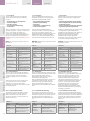
–2.2.1 OPERATING MODES
EntelliGuard G Trip Units have four operating
modes: Setup, Meter, Status and Events. These
are accessed through the five keys on the Trip
Unit front.
-- UP: Scroll up or increment value
-- DOWN: Scroll down or decrement value
-- RIGHT: Next function or next page
-- LEFT: Previous function or previous page
-- ENTER: Save or set in to memory
-2.2.1 BETRIEBSARTEN
EntelliGuard G Auslöseeinheiten können vier
Betriebsarten: Einrichten (SETUP), Messen
(ZÄHLER), ZUSTAND und Vorgänge (VORFALL)
anzeigen. Diese Anzeigen werden über die fünf
Tasten auf der Auslöseeinheiten Front
vorgenommen.
-- UP: Nach oben blättern oder Werte erhöhen
-- DOWN: Nach unten oder Werte verringern
-- RIGHT: Nächste Funktion oder nächste Seite
-- LEFT: Vorherige Funktion, o. vorherige Seite
-- ENTER: Speichern oder in den Speicher setzen.
-2.2.1 TRYBY PRACY
Wyzwalacze nadprądowe wyłączników
EntelliGuard G posiadają cztery tryby pracy:
Setup (Ustawienia), Meter (Pomiary), Status (Stan)
oraz Events (Zdarzenia). Dostęp do nich uzyskuje
się przy pomocy pięciu przycisków na panelu
obsługowym:
-- UP (W GÓRĘ): Przejście w górę lub zwiększenie
wartości
-- DOWN (W DÓŁ): Przejście w dół lub
zmniejszenie wartości
-- RIGHT (W PRAWO): Następna funkcja lub
następna strona
-- LEFT (W LEWO): Poprzednia funkcja lub strona
-- ENTER: Zapisanie lub ustawienie w pamięci
OPERATION
2.2 OPERATION
GENERAL
TRIP UNIT
PRODUCT
INTRO
Fig 2.2 Key pad
Abb. 2.2 Tasten
Fot. 2.2
Up
Down
Right (Next)
Left (Previous)
Oben
Unten
Rechts (Nächster)
Links (Voriger)
W górę
W dół
W prawo (Następny)
W lewo (Poprzedni)
CONNECTION INSTALLATION
REGISTER
CURVES
SCREEN MODE
Enter (Save) Sichern
2-10
2.2.2 SETUP MODE
SETUP Mode programming must be performed
with the rating plug installed. This procedure
applies to all trip unit types.
The SETUP procedures should only be repeated if
the trip unit or the protection characteristics are
changed, requiring different set points and timedelays.
All trip units provide long time over current
protection, long time delay, and some form of
short circuit current protection when installed in
circuit breakers. All other functions are optional.
If a specific set of trip unit functions, such as
relaying or short time over-current protection is
not installed that function will not appear on the
trip unit display. Ignore setup mode instructions
for such functions.
The trip unit must be powered by one of the
indicated four methods during SETUP. (see par.
2.1.9)
-- Press UP or DOWN until the SETUP mode is
selected.
-- Press RIGHT or LEFT to access the functions in
the SETUP mode.
-- Press ENTER to save desired values.
-- Press RIGHT to advance to the next function.
2.2.2.1 Entering Set points into Memory
1. Press UP or DOWN to select SETUP.
2. Press LEFT or RIGHT to select the desired
protection to change.
3. Press UP or DOWN to change values. The
values will start flashing.
4. Press ENTER to store the value into the
memory. The displayed value stops flashing and
the save icon appears on the top of the LCD. This
indicates that the value has been stored in
memory and is active.
5. Confirm settings on the trip unit after making
changes by exiting and re-entering SETUP mode
and rechecking each changed setting.
Enter (Zapis)
2.2.2 SETUP (Einrichtungs-) Modus
Die SETUP-Modus Programmierung muss mit
installiertem Stromeinstellmodul geschehen.
Dieses Verfahren gilt für alle Auslöseeinheiten.
Das Setup-Verfahren sollte nur wiederholt
werden, wenn die Auslöse- oder
Schutzmerkmale geändert werden müssen oder
andere Zeitverzögerungen etc. verlangt werden.
Alle Auslöseeinheiten liefern LangzeitÜberstromschutz, Langzeitverzögerung und
einige Formen von Kurzschlussstrom-Schutz,
wenn sie im Leistungsschalter installiert sind.
Alle anderen Funktionen sind optional.
Wenn eine bestimmte Reihe von
Auslösefunktionen, wie z. B. Schutzrelais oder
Kurzschlussstrom-Schutz nicht installiert sind, so
wird die Funktion auch nicht auf der
Auslöseeinheit angezeigt. Ignorieren Sie deshalb
die Setup-Anweisungen für solche Funktionen.
Das Auslösegerät muss nach einer der
beschriebenen Arten während des Setups
bedient werden: (siehe auch 2.1.9)
-- Drücken Sie UP (Rauf) oder DOWN (Runter), bis
der SETUP-Modus ausgewählt ist.
-- Drücken Sie RIGHT (Rechts) oder LEFT (Links),
für den Funktionszugriff im SETUP-Modus.
-- Drücken Sie die ENTER (Eingabetaste), um
gewünschten Werte zu sichern.
-- Drücken Sie RIGHT (Rechts), um zur nächsten
Funktion zu gelangen.
2.2.2.1 Eingabe der Sollwerte in den Speicher
1. Drücken Sie OBEN oder UNTEN, um SETUP zu
selektieren.
2. Drücken Sie LINKS oder RECHTS, um die
gewünschte Schutzart zu ändern.
3. Drücken Sie RAUF oder RUNTER, um Werte zu
ändern. Die Werte beginnen zu blinken.
4. Drücken Sie ENTER, um den Wert in den
Speicher zu setzen. Der angezeigte Wert blinkt
dann nicht mehr und das Sicherungssymbol
erscheint auf dem oberen Rand des LCDMonitors. Dies deutet darauf hin, dass der Wert
gespeichert wurde und aktiv ist.
5. Testen Sie die Einstellung der Auslöseeinheit
nach einer Änderung durch verlassen und
wieder in den SETUP-Modus springen, um jede
neue Einstellung zu überprüfen.
2.2.2 TRYB SETUP (USTAWIENIA)
Programowanie w trybie SETUP (USTAWIENIA)
wymaga podłączenia modułu nastawczego.
Procedura dotyczy wszystkich wersji
wyzwalaczy.
Procedury trybu SETUP należy powtórzyć tylko
po wymianie wyzwalacza lub gdy zmieniane są
charakterystyki zabezpieczeń, wymagające
innych nastaw prądowych i czasowych.
Wszystkie wyzwalacze nadprądowe instalowane
w wyłącznikach umożliwiają ochronę
przeciążeniową długozwłoczną, a także różne
rodzaje ochrony przed zwarciami. Pozostałe
funkcje są opcjonalne.
Jeśli określona funkcja, np. sterowanie
przekaźnikowe lub zabezpieczenie zwarciowe
krótkozwłoczne nie jest zainstalowana wówczas
nie będzie widoczna na wyświetlaczu. Instrukcje
trybu SETUP dla niezainstalowanej funkcji należy
pominąć.
W czasie pracy w trybie SETUP wyzwalacz musi
być zasilany jedną z czterech metod opisanych
w rozdziale 2.1.9.
-- Wcisnąć UP lub DOWN aż do wybrania SETUP
-- Wcisnąć RIGHT lub LEFT aby wejść do funkcji
trybu SETUP
-- Wcisnąć ENTER aby zapisać wybrane wartości
-- Wcisnąć RIGHT aby przejść do następnej
funkcji
2.2.2.1 Wprowadzanie nastaw do pamięci
1. Wcisnąć UP lub DOWN aby wyszukać SETUP
2. Wcisnąć LEFT lub RIGHT aby wybrać
zabezpieczenie do zmiany
3. Wcisnąć UP lub DOWN aby zmienić wartości.
Wartości zaczną migać.
4. Wcisnąć ENTER aby zapisać daną wartość w
pamięci. Miganie wartości ustaje i ukazuje się
ikona zapisu w górnej części wyświetlacza LCD.
Oznacza to, że wartość została zapisana w
pamięci i jest aktywna.
5. Sprawdzić zmienione ustawienia wyzwalacza
poprzez wyjście i ponowne wejście do SETUP
oraz odczytanie każdej ze zmienionych wartości.
EntelliGuard G
TRIP UNIT
2.2.3.1 Long Time Pickup
(Overload Protection setting) Ir
Installed in all Trip Units types the first SETUP
mode display is always the Long Time Pickup
setpoint. This set point establishes the breaker's
ampere rating Ir.
2.2.3.1 Langzeiteinstellungen
(Überlastschutz Einstellung) Ir
In allen Auslöserarten wurde als erste SETUPModusanzeige immer die Langzeit-SollwertEinstellung installiert. Dieser Sollwert richtet den
Leistungsschalter Stromwert Ir ein.
2.2.3.1 Ustawienia zabezpieczenia
przeciążeniowego (długozwłocznego) Ir
We wszystkich wyzwalaczach nadprądowych w
pierwszej kolejności wyświetlana jest nastawa
prądowa przeciążeniowa. Ustala ona prąd
znamionowy ciągły wyłącznika Ir.
The 1st screen allows the user to define up to 6
different user currents Ie that can be set as a
fraction of 1, 0.98, 0.97, 0.96,0.45 or 0.4 x the
breaker current rating In. These are indicated as
a current value on the screen
Das erste Display ermöglicht die Definition, von
bis zu 6 verschiedenen Nutzerströmen Ie, d.h. sie
können als ein Bruchteil von 1, 0,98, 0,97,
0.96,0.45 oder 0,4 x der Schalterstromwerte In
eingegeben werden. Diese werden als
Stromwert auf dem Display angezeigt.
Die definierte Stromeinstellung Ir wird am 2. LTEinstellbildschirm als ein Bruchteil des
Stromwerts Ie gesetzt. (xLT = LT Verstärker xIe).
Pierwszy ekran pozwala określić 6 różnych
wartości prądu użytkownika Ie, obliczanych jako
iloczyn współczynników: 1, 0.98, 0.97, 0.96, 0.45,
0.4 oraz prądu znamionowego In wyłącznika. Są
one wyświetlane na ekranie jako wartość prądu.
Sprecyzowana wartość nastawy prądowej Ir jest
ustawiana na drugim ekranie ustawień LT jako
iloczyn (ułamek) prądu użytkownika Ie (xLT =
mnożnik LT x Ie).
Do wyboru jest 11 nastaw długozwłocznych w
zakresie krotności od 0.50 do 1.00 x CT
zmienianych w krokach 0.05.
Wartość wybrana jest ustawiana na poziomie w
przybliżeniu równym '1.12 x nastawa' z
tolerancją od -10% do +10%. Dodatkowe
obniżenie dokładności rzędu ±5% ma miejsce
wtedy, gdy występują znaczne odkształcenia
harmoniczne. Przegląd możliwych ustawień
znajduje się w tabeli 2.4 na str. 2-12.
2.2.3.1.1 Ustawienia czasowe długozwłoczne
LTD (dla ochrony przeciążeniowej)
Wyzwalacz nadprądowy EntelliGuard GT-H
oferuje do wyboru 22 ustawienia czasowe
długozwłoczne dla charakterystyk o kształcie
zbliżonym do elementu termicznego w
wyłączniku z wyzwalaczem
termomagnetycznym. Maksymalne i minimalne
zwłoki czasowe oraz ich klasyfikacja wg normy
IEC 947 są przedstawione w tabeli 2.3. Dostępny
jest drugi zestaw 22 charakterystyk zwłocznych
o kształcie zbliżonym do ch-yk standardowych
bezpieczników. Minimalne i maksymalne czasy
opóźnień oraz ich klasyfikacja wg IEC 947 są
przedstawione w tabeli 2.3. Pasma tolerancji są
przedstawione jako charakterystyki czasowopradowe w załączniku 3.1 do tej instrukcji.
2.2.3.2 Ustawienia zabezpieczenia
zwarciowego krótkozwłocznego ST
Drugim w kolejności ekranem wyświetlanym w
trybie SETUP we wszystkich wersjach
wyzwalaczy są ustawienia ochrony zwarciowej
krótkozwłocznej.
Nastawa prądowa zwarciowa krótkozwłoczna
określa wartość prądu, przy której aktywowane
jest wyzwalanie krótkozwłoczne (Ist), ustawiane
w funkcji nastawy długozwłocznej Ir.
Ustawienia można wybrać w zakresie od 1.5 do
The definite current setting Ir is set on the 2nd LT
setting screen as a fraction of the user current
value Ie. (xLT = LT multiplier x Ie).
There are 11 Long Time Pickup settings ranging
from are 0.50 to 1.00 times x CT in steps of 0.05.
The pickup value is set at a value of
approximately 1.12 x the setting with a
tolerance of -10% to +10%. An additional
accuracy degradation of ±5% occurs when
waveforms with significant harmonic distortion
are present. (For an overview of all available
settings see table 2.4 on page 2-12)
2.2.3.1.1 Long Time Delay
(On overload Protection) LTD
The EntelliGuard GT-H trip unit types offer 22
long time delay bands that have a shape similar
to that of the thermal element of a thermal
magnetic circuit breaker.
The minimum and maximum delay times and
their IEC 947 classification are indicated in table
2.3. A second set of 22 delay bands is available
that offers a shape similar to that of standard
fuses. The minimum and maximum delay times
and their IEC 947 classification is indicated in
table 2.3. All 4 bands are depicted as Time
Current Diagram in appendix 3.1 of this
Application manual.
2.2.3.2 Short Time Pickup
(Delayed Short Circuit Protection) ST
Installed in all Trip Units types the second SETUP
mode display is always the Short Time Pickup set
point. The Short Time Pickup function
establishes the current at which a timed short
time trip is activated (Ist) and is adjusted in
function of the Long Time Pickup setting Ir. The
choices of pickup settings are from 1.5 to 12.0 (1)
times the long time setting, xLT ( Ir) , in steps of
0.5 xLT (Ir). see table 2.5.
Es gibt 11 Überlastschutz-Einstellungen im
Bereich von 0,50 bis 1,00 x CT in Schritten von
0,05. Der Spitzenwert ist annähernd der 1,12
fache Einstellwert mit einem Toleranzbereich
von -10% bis +10%. Eine zusätzliche
Herabsetzung der Genauigkeit um ± 5% tritt für
Kurvenformen mit erheblicher harmonischer
Verzerrung ein. (siehe Tab. 2.4 Seite 2-12)
2.2.3.1.1 Langzeitverzögerung
(für Überlastschutz) LTD
Die EntelliGuard GT-E, GT-S & GT-N
Auslöseeinheiten bieten 22 LangzeitVerzögerungsbereiche, die der Verzögerungsart
der thermischen Elemente eines thermischmagnetischen Leistungsschalter ähneln. Ein
zweiter Satz von 22 Langzeitbereichen bilden
eine Verzögerung ähnlich der StandardSicherungen. Die minimalen und maximalen
Verzögerungszeiten und ihre IEC 947
Klassifikation ist in Tab. 2.3 aufgezeigt. Die
Bereiche sind dargestellt als Zeit-StromDiagramm im Anhang 3.1.
2.2.3.2 Kurzzeitverzögerung
(verzögerter Kurzschlussschutz) ST
In allen Arten von Auslöseeinheiten zeigt der
zweite SETUP-Modus immer den
Kurzzeitverzögerungs-Einstellwert. Durch die
Kurzzeitverzögerungs-Funktion wird der Strom
gesetzt, auf dem eine zeitliche KurzzeitAuslösung aktiviert (Ist) ist, in Abhängigkeit zur
Langzeitauslösungs-Einstellung Ir. Die Wahl der
Einstellungen liegt zwischen 1,5 und 12,0 (1) mal
der Langzeit-Einstellung, xLT (Ir), in Schritten von
0,5 xLT (Ir). siehe Tab. 2.5.
Der ST Einstellwert (Ist)-Toleranzbereich beträgt -
OPERATION
2.2
Table 2.3 : Overload Tripping times at indicated overload levels per selected LTD band , in Seconds.
Tab. 2.3: Überlast-Auslösezeiten (sec)...
Tabela 2.3 : Czasy wyzwalania przeciążeniowego przy określonych poziomach przeciążeń dla wybranych ustawień czasowych LTD, w sekundach.
x Ir
Cmin
C-2
C-3
C-4
C-5
C-6
C-7
C-8
C-9
C-10
C-11
C-12
C-13
C-14
C-15
C-16
C-17
C-18
C-19
C-20
C-21 Cmax
1.5
Maximum
7.8
23.4
46.7
62.3
93.4
125
156
187
218
249
280
311
374
436
498
560
623
685
747
810
872
934
Minimum
4.0
12.0
24.0
32.0
48.0
64.1
80.1
96.1
112
128
144
160
192
224
256
288
320
352
384
416
448
480
3
Maximum
1.3
3.86
7.73
10.3
15.5
20.6
25.8
30.9
36.1
41.2
46.4
51.5
61.8
72.1
82.4
92.7
103
113
124
134
144
155
Minimum
0.80
2.41
4.82
6.43
9.64
12.9
16.1
19.3
22.5
25.7
28.9
32.1
38.6
45.0
51.4
57.8
64.3
70.7
77.1
83.6
90.0
96.4
7.2
Maximum
0.21
0.62
1.24
1.66
2.49
3.32
4.15
4.98
5.81
6.64
7.47
8.30
9.96
11.6
13.3
14.9
16.6
18.3
19.9
21.6
23.2
24.9
Minimum
0.13
0.40
0.81
1.07
1.61
2.15
2.69
3.22
3.76
4.30
4.83
5.37
6.45
7.52
8.60
9.67
10.7
11.8
12.9
14.0
15.0
16.1
10b
Motor Protection Class to IEC 947-4
Motorschutz-Klasse nach IEC 947-4
Kategoria ochrony silników wg IEC 947-4
1.5
3
7.2
10
20
30
40
x Ir
Fmin
F-2
F-3
F-4
F-5
F-6
F-7
F-8
F-9
F-10
F-11
F-12
F-13
F-14
F-15
F-16
F-17
F-18
F-19
F-20
F-21 Fmax
Maximum
1.44
4.19
7.62
11.9
17.2
23.9
32.3
42.8
56
72
93
118
150
190
239
302
380
477
600
752
942
1153
Minimum
Maximum
0.64
0.09
1.87
0.26
3.39
0.48
5.30
0.74
7.67
1.08
10.7
1.50
14.4
2.01
19.0
2.67
25
3.49
32
4.51
41
5.80
53
7.39
67
9.39
85
11.9
107
15.0
135
18.9
169
23.8
213
29.9
267
37.5
335
47.0
419
58.9
514
72.1
Minimum
0.04
0.12
0.21
0.33
0.48
0.67
0.90
1.19
1.55
2.01
2.57
3.29
4.18
5.29
6.68
8.41
10.6
13.3
16.7
20.9
26.2
32.1
Maximum
0.07
0.08
0.09
0.11
0.12
0.14
0.18
0.22
0.28
0.36
0.45
0.57
0.72
0.90
1.13
1.42
1.78
2.18
Minimum
0.01
0.02
0.03
0.04
0.05
0.06
0.08
0.10
0.13
0.16
0.20
0.25
0.32
0.40
0.50
0.63
0.79
1.03
2-11
EntelliGuard G
INTRO
TRIP UNIT
APPENDIX
= primary current settings Ie | Stromeinstellung Ie | | Podstawowa nastawa prądowa Ie (A)
= secondary current settings Ir | Stromeinstellung Ir | Nastawa prądowa przeciążeniowa Ir (A)
Breaker In
Breaker In
Multip. Primary Setting Ie and Secondary Setting Ir values in AMPS
Multip. Primary Setting Ie and Secondary Setting Ir values in AMPS
Schalter In
Primäreinstellung Ie (A) / Sekundäreinstellung Ir (A)
Schalter In
Faktor Primäreinstellung Ie (A) / Sekundäreinstellung Ir (A)
Faktor
Prąd In wył-ka Mnożnik Podstawowa nastawa prądowa Ie (A) / Nastawa prądowa przeciążeniowa Ir(A) Prąd In wył-ka Mnożnik Podstawowa nastawa prądowa Ie (A) / Nastawa prądowa przeciążeniowa Ir (A)
400
PRODUCT
GENERAL
Table 2.4: Indicating available Long time settings
Tab. 2.4: Umrechnungstabelle der verfügbaren Langzeiteinstellungen
Tabela 2.4: możliwe nastawy długozwłoczne
800
1000
CONNECTION INSTALLATION
REGISTER
CURVES
SCREEN MODE
OPERATION
630
2-12
1250
1600
1
0,95
0,9
0,85
0,8
0,75
0,7
0,65
0,6
0,55
0,5
1
0,95
0,9
0,85
0,8
0,75
0,7
0,65
0,6
0,55
0,5
1
0,95
0,9
0,85
0,8
0,75
0,7
0,65
0,6
0,55
0,5
1
0,95
0,9
0,85
0,8
0,75
0,7
0,65
0,6
0,55
0,5
1
0,95
0,9
0,85
0,8
0,75
0,7
0,65
0,6
0,55
0,5
1
0,95
0,9
0,85
0,8
0,75
0,7
0,65
0,6
0,55
0,5
400
390
385
380
180
160
380
360
340
320
300
280
260
240
220
200
371
351
332
312
293
273
254
234
215
195
366
347
327
308
289
270
250
231
212
193
361
342
323
304
285
266
247
228
209
190
171
162
153
144
135
126
117
108
99
90
152
144
136
128
120
112
104
96
88
80
630
615
610
605
280
250
599
567
536
504
473
441
410
378
347
315
584
554
523
492
461
431
400
369
338
308
580
549
519
488
458
427
397
366
336
305
575
545
514
484
454
424
393
363
333
303
266
252
238
224
210
196
182
168
154
140
238
225
213
200
188
175
163
150
138
125
800
784
776
768
350
315
760
720
680
640
600
560
520
480
440
400
745
706
666
627
588
549
510
470
431
392
737
698
660
621
582
543
504
466
427
388
730
691
653
614
576
538
499
461
422
384
333
315
298
280
263
245
228
210
193
175
299
284
268
252
236
221
205
189
173
158
1000
980
970
960
450
400
950
900
850
800
750
700
650
600
550
500
931
882
833
784
735
686
637
588
539
490
922
873
825
776
728
679
631
582
534
485
912
864
816
768
720
672
624
576
528
480
428
405
383
360
338
315
293
270
248
225
380
360
340
320
300
280
260
240
220
200
1250
1225
1210
1196
560
500
1188
1125
1063
1000
938
875
813
750
688
625
1164
1103
1041
980
919
858
796
735
674
613
1150
1089
1029
968
908
847
787
726
666
605
1136
1076
1017
957
897
837
777
718
658
598
532
504
476
448
420
392
364
336
308
280
475
450
425
400
375
350
325
300
275
250
1600
1568
1552
1536
720
630
1520
1440
1360
1280
1200
1120
1040
960
880
800
1490
1411
1333
1254
1176
1098
1019
941
862
784
1474
1397
1319
1242
1164
1086
1009
931
854
776
1459
1382
1306
1229
1152
1075
998
922
845
768
684
648
612
576
540
504
468
432
396
360
599
567
536
504
473
441
410
378
347
315
2000
2500
3200
4000
5000
6400
1
0,95
0,9
0,85
0,8
0,75
0,7
0,65
0,6
0,55
0,5
1
0,95
0,9
0,85
0,8
0,75
0,7
0,65
0,6
0,55
0,5
1
0,95
0,9
0,85
0,8
0,75
0,7
0,65
0,6
0,55
0,5
1
0,95
0,9
0,85
0,8
0,75
0,7
0,65
0,6
0,55
0,5
1
0,95
0,9
0,85
0,8
0,75
0,7
0,65
0,6
0,55
0,5
1
0,95
0,9
0,85
0,8
0,75
0,7
0,65
0,6
0,55
0,5
2000
1960
1940
1920
900
800
1900
1800
1700
1600
1500
1400
1300
1200
1100
1000
1862
1764
1666
1568
1470
1372
1274
1176
1078
980
1843
1746
1649
1552
1455
1358
1261
1164
1067
970
1824
1728
1632
1536
1440
1344
1248
1152
1056
960
855
810
765
720
675
630
585
540
495
450
760
720
680
640
600
560
520
480
440
400
2500
2450
2425
2400
1125
1000
2375
2250
2125
2000
1875
1750
1625
1500
1375
1250
2328
2205
2083
1960
1838
1715
1593
1470
1348
1225
2304
2183
2061
1940
1819
1698
1576
1455
1334
1213
2280
2160
2040
1920
1800
1680
1560
1440
1320
1200
1069
1013
956
900
844
788
731
675
619
563
950
900
850
800
750
700
650
600
550
500
3200
3136
3104
3072
1440
1280
3040
2880
2720
2560
2400
2240
2080
1920
1760
1600
2979
2822
2666
2509
2352
2195
2038
1882
1725
1568
2949
2794
2638
2483
2328
2173
2018
1862
1707
1552
2918
2765
2611
2458
2304
2150
1997
1843
1690
1536
1368
1296
1224
1152
1080
1008
936
864
792
720
1216
1152
1088
1024
960
896
832
768
704
640
4000
3920
3880
3840
1800
1600
3800
3600
3400
3200
3000
2800
2600
2400
2200
2000
3724
3528
3332
3136
2940
2744
2548
2352
2156
1960
3686
3492
3298
3104
2910
2716
2522
2328
2134
1940
3648
3456
3264
3072
2880
2688
2496
2304
2112
1920
1710
1620
1530
1440
1350
1260
1170
1080
990
900
1520
1440
1360
1280
1200
1120
1040
960
880
800
5000
4900
4850
4800
2250
2000
4750
4500
4250
4000
3750
3500
3250
3000
2750
2500
4655
4410
4165
3920
3675
3430
3185
2940
2695
2450
4608
4365
4123
3880
3638
3395
3153
2910
2668
2425
4560
4320
4080
3840
3600
3360
3120
2880
2640
2400
2138
2025
1913
1800
1688
1575
1463
1350
1238
1125
1900
1800
1700
1600
1500
1400
1300
1200
1100
1000
6400
6272
6208
6144
2880
2560
6080
5760
5440
5120
4800
4480
4160
3840
3520
3200
5958
5645
5331
5018
4704
4390
4077
3763
3450
3136
5898
5587
5277
4966
4656
4346
4035
3725
3414
3104
5837
5530
5222
4915
4608
4301
3994
3686
3379
3072
2736
2592
2448
2304
2160
2016
1872
1728
1584
1440
2432
2304
2176
2048
1920
1792
1664
1536
1408
1280
EntelliGuard G
TRIP UNIT
2.2
x Ir
1.5 x
±10%
12 x
±10%
Min
2
3
4
5
6
7
8
9
10
11
12
13
14
15
16
Max
Tripping
90
100
110
120
170
190
240
270
300
340
400
450
600
700
800
900
1000
Non Tripping
30
40
50
60
110
130
180
210
240
280
340
390
540
640
740
840
940
Tripping
90
100
110
120
170
190
240
270
300
340
400
450
600
700
800
900
1000
Non Tripping
30
40
50
60
110
130
180
210
240
280
340
390
540
640
740
840
940
(1) On Envelope 3 type limited to 10 x Ir. (2)Timings in Red meet the requirements of the IEC 60479-1 and IEC 60364 standards at a frequency of 50 cycles.
(1) Baugröße 3 limitiert auf 10 x Ir.- (2) Rote Eintragungen stimmen mit den Anforderungen von IEC 60479 mit einer Frequenz von 50 Hz überein.
(1) Dla wielkości gabarytowych 3 ograniczenie do 10 x Ir. (2) Czasy zaznaczone czerwoną czcionką spełniają wymagania normy IEC 60479-1 oraz IEC 60364 przy częstotliwości 50Hz.
The ST pickup value (Ist) tolerance band is -10%
to +10% of the set point. An additional accuracy
degradation of ±5% shall be allowed for
waveforms with significant harmonic distortion.
10% bis +10% des Einstellwertes. Eine
zusätzliche Genauigkeitsabweichung von ± 5%
tritt für Kurvenformen mit erheblicher
harmonischer Verzerrung ein.
2.2.3.2.1 Short Time Delay STDB
(Delay on delayed Short Circuit Protection)
The EntelliGuard GT-H trip unit types offer a
Short Time Delay function with both a slope
setting and a fixed delay band setting. The slope
and delay are independently selectable. The
slope setting consists of three I²t slopes (1, 2, 3)
and a fixed delay. The fixed delay bands have 17
constant time bands.
The minimum and maximum delay times are
indicated in table 2.5.
The bands of both the slope and fixed delay
types are depicted as Time Current Diagram in
appendix 3.1 of this Application manual.
2.2.3.2.1 Kurzzeit-Verzögerung STDB
(Verzögerung auf verzögerten
Kurzschlussschutz)
Die EntelliGuard GT-H Auslöseeinheiten bieten
eine Kurzzeit-Verzögerungsfunktion mit beiden,
einer Steigerungs- und einer festen
Verzögerungs-Bereichseinstellung. Die
Steigungen und Verzögerungen sind
unabhängig wählbar. Die Steigungseinstellung
besteht aus drei I²t (1, 2, 3) und einer festen
Verzögerung. Der feste Verzögerungsbereich hat
17 konstante Zeitbereiche. Die minimalen und
maximalen Verzögerungen werden in Tab. 2.5
dargestellt. Die Bereiche beider, die Steigung und
feste Verzögerungsart, werden als
Auslösekurven in der Anlage 3.1 dargestellt.
2.2.3.3 Selective Instantaneous Protection (I)
Installed in all Trip Units types GT-H the third
SETUP mode display is the adjustable Selective
Instantaneous over current protection.
This device causes an undelayed breaker trip
when the chosen current level (Ii) and proper
waveform is reached. The pickup value may be
set in steps of 0.5 x the set user current value Ie
from 2.0 xIe to 15 xIe.
2.2.3.3 Selektive Schnellauslösung (I)
In allen Auslöseeinheiten Typ GT-H, des dritten
SETUP-Modusdisplays ist der einstellbare
selektive Kurzschlussschnell-Auslösungsschutz
installiert.
Dieser Schutz verursacht eine verzögerungsfreie
Schalterauslösung, wenn das gewählte
Stromniveau (Ii) und die ordnungsgemäße
Kurvenform erreicht ist. Der Einstellwert kann in
Schritten von 0,5 x auf die eingestellten NutzerStromwerte von 2,0 xIe bis 15 xIe gesetzt
werden.
Einige GT-H Ausführungen sind mit einem
erweitertem Schnellauslösungsschutz
ausgerüstet. Dieser erreicht die maximale (Ii)
Einstellung von 10 bis 30 x Ie. Die Einstellstufung
bei 2-15 x Ie erfolgt in 0,5 er Schritten, die
Some GT-H executions are are equipped with a
extended instantaneous over current protection.
This extends the maximum (Ii) setting from 15 to
30 x Ie. The _pickup value may be set in steps of
0.5 x the set user current value Ie from 2.0 xIe to
15 xIe and in steps of 1 xIe from 15 to 30 x Ie
Table 2.6: HSIOC devices
Overview of installed
HSIOC devices in
Automatic types:
| Set values (rms)
Envelope 1
Tab. 2.6: HSIOC Schutz
Übersicht über
HSIOC Geräte in
Automatik Typen:
| Werte (rms)
Baugröße 1
GG04 S ... GG20S
GG04N ... GG20N
50.000 A
65.000 A
Envelope 2
GG04 S ... GG20S
GG04N ... GG20N
50.000 A
65.000 A
GG25N ... GG40N
GG04E ... GG20E
GG25H ... GG40H
GG25M ... GG40M
65.000 A
85.000 A
85.000 A
85.000 A
GG32G ... GG40G
GG40M ... GG64M
GG40L ... GG64L
100.000 A
100.000 A
100.000 A
Baugröße 2
GG25N ... GG40N
GG04E ... GG20E
GG25H ... GG40H
GG25M ... GG40M
65.000 A
85.000 A
85.000 A
85.000 A
GG32G ... GG40G
GG40M ... GG64M
GG40L ... GG64L
100.000 A
100.000 A
100.000 A
Envelope 3
Baugröße 3
12.0 (1) krotności nastawy prądowej
długozwłocznej, xLT (Ir), w krokach 0.5 x LT - patrz
tabela 2.5.
Dokładność nastawy prądowej ST (Ist) wynosi od 10% do +10% ustawionej wartości. Dodatkowe
obniżenie dokładności rzędu ±5% ma miejsce
wtedy, gdy występują znaczne zniekształcenia
harmoniczne.
OPERATION
Table 2.5 : Short Time tripping times at indicated levels per selected STDB band -I²t OFF. in ms (2)
Tab. 2.5: Kurzzeit-Auslösung...
Tabela 2.5 : Czasy wyzwalania zabezp. krótkozwłocznego przy określonych poziomach prądu dla wybranych charakterystyk STDB -I2t OFF, w ms (2)
2.2.3.2.1 Ustawienia czasowe zabezpieczenia
zwarciowego zwłocznego STDB
Wyzwalacze GT-H oferują zabezpieczenie
zwarciowe krótkozwłoczne z charakterystyką
zależną o ustawianym nachyleniu, oraz z
charakterystyką niezależną o stałej nastawie
czasowej. Nachylenia i czas zwłoki są ustawiane
niezależnie. W ustawieniach nachylenia można
wybrać jedną z trzech charakterystyk I²t (1, 2, 3)
oraz stałe opóźnienie. Stałe opóźnienie można
wybrać spośród 17 nastaw / charakterystyk
czasowych. Maksymalne i minimalne ustawienia
czasowe są podane w tabeli 2.5. Pasma tolerancji
zarówno dla opóźnień czasowych zależnych jak i
stałych są przedstawione w formie charakterystyk
czasowo-prądowych w załączniku 3.1 do tej
instrukcji.
2.2.3.3 Zabezpieczenie bezzwłoczne
selektywne (I)
We wszystkich wyzwalaczach GT-H trzeci ekran
wyświetlacza w menu SETUP umożliwia
wprowadzanie ustawień dla nastawnego
selektywnego zabezpieczenia zwarciowego
bezzwłocznego.
Powoduje ono natychmiastowe wyzwolenie
wyłącznika, gdy prąd przekracza nastawioną
wartość (Ii). Wartość progowa jest ustawiana w
zakresie od 2,0 xIe do 15 xIe w krokach równych 0,5
x Ie (Ie - prąd ustawiony przez użytkownika).
Niektóre wykonania GT-H są wyposażone w
rozszerzone zabezpieczenie nadprądowe
bezzwłoczne. Posiada ono rozszerzony zakres
Tabela 2.6: Wyzwalacze HSIOC |
Przegląd wyzwalaczy
HSIOC wbudowanych w
wyłącznikach:
Nastawy (rms)
Gabaryt 1
GG04 S ... GG20S
GG04N ... GG20N
50.000 A
65.000 A
GG25N ... GG40N
GG04E ... GG20E
GG25H ... GG40H
GG25M ... GG40M
65.000 A
85.000 A
85.000 A
85.000 A
GG32G ... GG40G
GG40M ... GG64M
GG40L ... GG64L
100.000 A
100.000 A
100.000 A
Gabaryt 2
Gabaryt 3
2-13
CONNECTION INSTALLATION
REGISTER
CURVES
SCREEN MODE
OPERATION
PRODUCT
GENERAL
EntelliGuard G
INTRO
The Instantaneous pickup accuracy is 10%. The
GT-H trip units have a user-selectable
switchable instantaneous over current , an
additional value of OFF appears at the end of the
listing of numerical values. Choose this setting to
disable instantaneous protection.
The bands are depicted as Time Current
Diagram in appendix 3.1 of this Application
manual.
ST and I setting Limitations
In some cases the stated maximum settable
Short time current and instantaneous current
value can exceed the Short Time withstand
current capabilities of the breaker in which they
are installed.
The GT range of trip unit always detects the
breaker in which it is installed and where needed
limits the indicated settable values as per table
2.6a and 2.6b.
APPENDIX
Einstellung von 15-30 x Ie in 1 x Ie Stufen.
Die Schnellauslösungs-Einstellungsgenauigkeit
liegt bei 10%. Die GT-H Auslöseeinheiten haben
einen vom Anwender wählbaren
Schnellauslösungs-Überstrom, ein zusätzlicher
AUS-Wert erscheint am Ende der Auflistung der
Zahlen. Wählen Sie diese Einstellung zum
deaktivieren des Schutzes.
Die Bereiche sind als Auslösekurven in diesem
Handbuch (Abschnitt 3.1) dargestellt.
ST und I (Kurzschluss) Begrenzungen
In einigen Fällen kann der angegebene
maximale einstellbare Kurzschlussstrom- und
Schnellauslösungsstrom-Wert die
BemessungskurzzeitstromfestigkeitEinsatzmöglichkeit des Schalters überschreiten,
in dem der Schutz installiert ist. Die GTAuslöseeinheiten erkennen immer den Schalter,
in dem sie installiert sind und die notwendigen
Grenzwerte nach den Tab. 2.6a und 2.6b.
nastaw (Ii) od 15 do 30 x Ie. Wartość progowa może
być ustawiana w krokach 0,5 x Ie (Ie - prąd
ustawiany przez użytkownika) od krotności 2,0 x Ie
do 15 x Ie oraz w krokach 1 x Ie od krotności 15 do
30 x Ie.
Dokładność nastaw zabezpieczenia bezzwłocznego
wynosi 10%. W wyzwalaczach GT-H użytkownik ma
możliwość wyłączenia zabezpieczenia
bezzwłocznego używając ustawienia OFF
występującego na końcu listy wartości liczbowych.
Po jego wybraniu zabezpieczenie bezzwłoczne jest
wyłączone.
Pasma tolerancji charakterystyk czasowoprądowych są przedstawione w załączniku 3.1 do
tej instrukcji.
Ograniczenia nastaw dla zabezpieczeń ST i I
W niektórych przypadkach wyżej wspomniane
maksymalne wartości nastaw zabezpieczeń
zwarciowych: krótkozwłocznego i bezzwłocznego
mogą przekroczyć wytrzymałość zwarciową torów
prądowych wyłącznika w którym wyzwalacz jest
zabudowany.
Wyzwalacz serii GT zawsze wykrywa w jakiej wersji
wyłącznika jest zainstalowany, a gdy zachodzi
Table 2.6a Maximum settable ST or I settings
Tab. 2.6a Maximale ST oder I Einstellungen
Tabela 2.6a Maksymalne nastawy zabezpieczeń ST i I
Breaker Primary
Rating
setting
In
current Ie
Schalter Primäre
Strom Einstellung
Strom Ie
In
Prąd znam. Nastawa
wyłącznika prądowa
In
podst. Ie
5000A
6400A
5000A
6400A
2000A
2500A
3200A
4000A
5000A
6400A
2000A
2500A
3200A
4000A
5000A
6400A
Breaker Icw
50kA 65kA 85kA 100kA
Maximum ST setting (x Ir)
12 x
10x
5000A
6400A
5000A
6400A
2000A
2500A
3200A
4000A
5000A
6400A
2000A
2500A
3200A
4000A
5000A
6400A
Maximum standard or extended Ii settings (x Ie)
24x
30x
30x
30x
25x
30x
30x
20x
16x
26x
21x
30x
30x
17x
25x
Leistungsschalter Icw
50kA 65kA 85kA 100kA
Maximale ST Einstellwerte (x Ir)
12 x
10x
5000A
6400A
5000A
6400A
2000A
2500A
3200A
4000A
5000A
6400A
2000A
2500A
3200A
4000A
5000A
6400A
Prąd Icw wy-łka
50kA 65kA 85kA 100kA
Maks. nastawa ST (x Ir)
12 x
10x
Maksymalne standardowe lub
rozszerzone nastawy Ii (x Ie)
Maximale Standard oder erweiterte Ii Werte (x Ie)
24x
30x
30x
30x
25x
30x
30x
20x
16x
26x
21x
30x
30x
17x
25x
24x
30x
30x
30x
25x
30x
30x
20x
16x
26x
21x
30x
30x
17x
25x
Table 2.6b Breaker type and Breaker Icw.
Breaker
Breaker
Breaker
Icw rating
Rating Ie
Rating Ie
Type
in kA
minimum
maximum
GG - S
400A
2000A
50kA
GG - N
400A
4000A
65kA
GG - H
400A
2000A
65kA
GG - E
400A
2000A
85kA
GG - H
2500A
4000A
85kA
GG - M
400A
4000A
85kA
GG - G
3200A
4000A
100kA
GG - M
4000A
6400A
100kA
GG - L
3200A
6400A
100kA
Tabela 2.6b Wersja i prąd Icw wyłącznika
2.2.3.3.1 High Set Instantaneous Protection
(HSIOC)
HSIOC is also Known as Override Pickup. The trip
units used in EntelliGuard G circuit breakers are
provided with an override instantaneous trip:
-- The HSIOC setting is normally set at 107% of
the circuit breaker Icw rating when the
adjustable selective instantaneous is set to ON.
2.2.3.3.1 High-Kurzschlussstromschnellschutz
(HSIOC)
HSIOC ist auch bekannt als 'Override Pickup'. Die
Auslöseeinheiten der EntelliGuard G
Leistungsschalter sind mit einer 'Erweiterten
Schnellauslösung' versehen:
-- Die HSIOC Einstellung ist normalerweise auf
107% des Schalter Icw-Wertes gesetzt, wenn die
einstellbare selektive Schnellauslösung auf EIN
gesetzt wurde.
-- Wenn die einstellbare selektive
Schnellauslösung auf AUS gestellt ist, dann ist
der HSIOC nominale Einstellwert auf 98% des
Schalter Icw’s reduziert. Unter Berücksichtigung
der Toleranz, ist der niedrigste Reaktionswert
91% des Leistungsschalter Icw’s Wertes.
potrzeba – ograniczają możliwe nastawy do
wartości podanych w tabelach 2.6a i 2.6b.
-- If the adjustable selective instantaneous is set
to OFF then the HSIOC nominal pick up is
reduced to 98% of the circuit breaker’s Icw and,
considering tolerance, the minimum pickup
reacts at 91% of the circuit breaker’s Icw value.
2.2.3.4 Making Current Release (MCR)
Every EntelliGuard TU circuit breaker uses a
making current release that is specifically
designed to prevent damage to the circuit
breaker when it closed on a fault. In some cases
2-14
TRIP UNIT
2.2.3.4 Einschaltstromauslöser (MCR)
Jeder EntelliGuard TU-Leistungsschalter
verwendet einen Einschaltstromauslöser, speziell
zur Vermeidung von Schäden am
Leistungsschalter, wenn dieser auf einen Fehler
Wyłącznik
Wersja
GG - S
GG - N
GG - H
GG - E
GG - H
GG - M
GG - G
GG - M
GG - L
Prąd znam.
Ie wył-ka
minimalny
400A
400A
400A
400A
2500A
400A
3200A
4000A
3200A
Prąd znam.
Ie wył-ka
maksymalny
2000A
4000A
2000A
2000A
4000A
4000A
4000A
6400A
6400A
Prąd Icw
w kA
50kA
65kA
65kA
85kA
85kA
85kA
100kA
100kA
100kA
2.2.3.3.1 Zabezpieczenie wysokozwarciowe
natychmiastowe (HSIOC)
Zabezpieczenie HSIOC stosowane w wyzwalaczach
nadprądowych wyłączników EntelliGuard jest
również nazywane bezzwłocznym nadrzędnym.
-- Nastawa HSIOC jest zwykle ustawiona na
poziomie 107% znamionowego prądu zwarciowego
krótkotrwale wytrzymywanego (Icw) wyłącznika,
gdy włączone jest (ON) regulowane zabezpieczenie
bezzwłoczne selektywne.
-- Jeśli regulowane zabezpieczenie bezzwłoczne
selektywne jest wyłączone (OFF) wtedy nastawa
HSIOC jest obniżona do 98% Icw wyłącznika, a przy
uwzględnieniu tolerancji minimalny poziom
zadziałania wynosi 91% wartości Icw.
2.2.3.4 Zabezpieczenie przed załączeniem na
zwarcie (MCR)
Każdy wyłącznik EntelliGuard TU posiada
wyzwalacz chroniący przed załączeniem przy
zwarciu w instalacji, zapobiegający uszkodzeniu
TRIP UNIT
EntelliGuard G
2.2
Overview of installed MRC
devices in Automatic types :
Set value (rms)
Envelope 1
Tab. 2.7: Installierte MCR-Geräte
und deren Einstellungen
Übersicht installierte MRC
Geräte in Automatik-Typen:
Tabela 2.7: Wyzwalacze MCR i ich ustawienia
Einstellwerte (rms)
42,000 A
50,000 A
65,000 A
GG25N to GG40N
GG04E to GG20E
GG25H to GG40H
GG25M to GG40M
65,000
85,000
85,000
85,000
GG32G to GG40G
GG40M to GG64M
GG40L to GG64L
100,000 A
100,000 A
100,000 A
Envelope 2
GG04S ... GG20S
GG04N ... GG20N
GG04H ... GG20H
42,000 A
50,000 A
65,000 A
GG25N ... GG40N
GG04E ... GG20E
GG25H ... GG40H
GG25M ... GG40M
65,000
85,000
85,000
85,000
Envelope 3
GG32G ... GG40G
GG40M ... GG64M
GG40L ... GG64L
100,000 A
100,000 A
100,000 A
A
A
A
A
Set value (rms)
Envelope 1
Übersicht installierte MRC
inTrennerversionen:
Einstellwerte (rms)
65,000 A
Envelope 2
GW04N ... GW20N
85,000 A
65,000
85,000
85,000
85,000
GG32G ...GG40G
GG40M ...GG64M
GG40L ...GG64L
100,000 A
100,000 A
100,000 A
Wyzwalacze MCR stosowane
w rozłącznikach (niesamoczynnych):
65,000 A
A
A
A
A
Nastawa (w. skut.)
GW04N ...GW20N
65,000 A
GW04M ...GW40M
85,000 A
Gabaryt 2
Baugröße 2
GW04M to GW40M
GG25N ...GG40N
GG04E ...GG20E
GG25H ...GG40H
GG25M ...GG40M
Gabaryt 1
Baugröße 1
GW04N to GW20N
42,000 A
50,000 A
65,000 A
Gabaryt 3
Baugröße 3
Overview of installed MRC
devices in Non Automatic types :
GG04S ...GG20S
GG04N ...GG20N
GG04H ...GG20H
Gabaryt 2
Baugröße 2
A
A
A
A
Nastawa (w. skut.)
Gabaryt 1
Baugröße 1
GG04S to GG20S
GG04N to GG20N
GG04H to GG20H
Wyzwalacze MCR stosowane
w wyłącznikach (samoczynnych):
OPERATION
Table 2.7: Installed MCR devices and their settings
GW04M ... GW40M
85,000 A
non Automatic EntelliGuard G types are also
equipped with this kind of release.
The making current release value varies per
circuit breaker envelope and is related to the
circuit breaker’s close and latch rating as
indicated in table 2.7
The MCR pickup is activated at the time the
circuit breaker closes and for six cycles
thereafter. When the six cycles are over, the
threshold changes to the HSIOC pickup setting.
schaltet. In einigen Fällen sind EntelliGuard GTrennertypen auch mit solchen Modulen
ausgerüstet.
Die Einschaltstromauslöser Werte variieren je
nach Leistungsschalter-Baugröße und stehen im
Zusammenhang mit dem Leistungsschalter
Schließ- und Verriegelungswert, wie in Tab. 2.7
beschrieben.
Der MCR-Einstellwert ist zum Zeitpunkt der
Leistungsschalter Schließung und für sechs
Zyklen danach aktiviert. Wenn die sechs Zyklen
vorbei sind, ändert der Schwellenwert zur HSIOC
Einstellung.
wyłącznika wskutek zamknięcia na zwarcie. W
niektórych przypadkach również rozłączniki
(niesamoczynne) są wyposażone w taki
wyzwalacz.
Wartość progowa zadziałania tego wyzwalacza
jest zależna od wielkości wyłącznika oraz jego
znamionowego prądu zwarciowego
załączalnego, wg tabeli 2.7.
Wyzwalacz MCR jest aktywowany w czasie
zamykania wyłącznika, a następnie podczas
pierwszych sześciu okresów przebiegu prądu. Po
sześciu okresach wartość progowa zmienia się
na wartość nastawy HSIOC.
2.2.3.5 Reduced Energy Let-Through
Instantaneous Protection (RELT)
The EntelliGuard G Trip Unit type GT-H provides
a Reduced Let-Through Energy Instantaneous
function (RELT) which may be enabled at the
trip’s key pad, via a 24 VDC/AC signal to INPUT 1
or via serial communications. (Modbus if
installed)
The RELT function provides a faster
instantaneous trip function that may be used in
cases where a faster and more sensitive
protection against short circuits is required
temporarily.
The device is set separately and has a pickup
value that can be set in steps of 0.5 x the set
user current value Ie with a range of 1,5 xIe to
15 xIe. (limited to a maximum 13 x Ie on the
6400A type).
To allow the use of the RELT function a input
needs to be set to the RELT function and to 'ON'
in the trip unit set up menu . A relay output
indicating that the RELT is operational can be
optionally set up in the same manner.
(see paragraph 2.4)
2.2.3.5 RELT-Schutz (reduzierter Schnellschutz)
Die EntelliGuard G Auslöseeinheit Typ GT-H
bietet eine 'Reduced Energy Let-Through
Instantaneous Protection' RELT-Funktion, die
möglicherweise über die Auslösertastatur
freigegeben wird, über ein 24 VDC/AC Signal am
Eingang 1 oder über die serielle Kommunikation.
(Modbus falls installiert)
Die RELT-Funktion bietet eine schnellere
Schnellauslösungsfunktion, die verwendet
werden kann, wenn ein schnellerer und
empfindlicherer Schutz gegen Kurzschlüsse
vorübergehend erforderlich ist.
Das Gerät ist getrennt einstellbar und hat einen
Einstellwert, der in Schritten von 0,5 x auf den
gesetzten Nutzerstromwert Ie mit einer
Bandbreite von 1,5 xIe bis 15 xIe gestellt werden
kann.(beschränkt auf max. 13 xIe für den 6400A
Typ).
Um die Verwendung der RELT-Funktion zu
nutzen, muss eine Eingang auf die RELT Funktion
gesetzt werden und 'EIN' im Menü eingerichtet
werden. Ein Relaisausgang der darauf hinweist,
dass die RELT-Funktion betriebsbereit ist kann
optional in gleicher Weise gesetzt werden. (siehe
Abschnitt 2.4)
2.2.3.5 Zabezpieczenie zwarciowe
bezzwłoczne obniżone (RELT)
Wyzwalacz w wersji GT-H posiada zabezpieczenie
bezzwłoczne RELT chroniące przed przepływem
znacznych prądów zwarciowych o dużej energii.
Funkcja może być aktywowana poprzez klawiaturę
wyzwalacza, poprzez sygnał napięciowy 24 VDC/AC
doprowadzony do WEJŚCIA 1(INPUT 1), lub poprzez
moduł komunikacyjny współpracujący z magistralą
Modbus (jeśli jest zainstalowany).
Funkcja RELT zapewnia szybsze działanie
zabezpieczenia zwarciowego bezzwłocznego.
Można ją wykorzystać w przypadku gdy celowa jest
tymczasowa szybsza i bardziej czuła ochrona przed
zwarciami.
Wyzwalacz jest ustawiany odrębnie, jego nastawy
można ustawiać w krokach 0.5 xIe (Ie - prąd
ustawiony przez użytkownika) w zakresie od 1,5 xIe
do 15 xIe (w wyłącznikach 6400A istnieje
ograniczenie do 13 xIe).
Aby możliwe było skorzystanie z funkcji RELT
konieczne jest jej włączenie poprzez odpowiednie
wejście oraz ustawienie wartości ON w menu
ustawień. Opcjonalnie możliwa jest sygnalizacja
działania funkcji RELT poprzez wyjście
przekaźnikowe ustawiane w analogiczny sposób
(patrz: rozdział 2.4).
2-15
CONNECTION INSTALLATION
REGISTER
CURVES
SCREEN MODE
OPERATION
PRODUCT
GENERAL
EntelliGuard G
INTRO
APPENDIX
2.2.3.6 Ground Fault Protection (GF)
The GT-H Trip Unit can optionally be equipped
with a ground fault protection that operates on
one of two principles:
-- residual principle. (GFsum)
-- Source Ground Return principle. (GFct)
2.2.3.6 Erdschlussschutz (GF)
Die GT-H-Auslöseeinheit kann optional mit
einem Erdschlussschutz ausgerüstet werden,
der nach einem der zwei Prinzipien arbeitet:
-- Fehlerstrom-Prinzip (GFsum)
-- Source Ground Return principle. (GFct)
The GFsum Ground Fault Protection
The device utilizes the internal Rogowski sensors
in the circuit breaker to measure and to
residually sum all phase and neutral currents.
When the groundfault option is chosen on a 3
pole breaker an additional 4th external sensor is
required for most applications (4 wire). The
distance between the circuit breaker and the
external sensor is limited to 10 metres. (33 f)
Das Fehlerstrom-Prinzip (GFsum)
Der Schutz nutzt die internen RogowskiWandler im Schalter zum Messen und zum
Summieren aller übrigbleibenden Phasen- und
Neutralströme. Wenn die Erdschluss-Option mit
einem 3-poligen Leistungsschalter gewählt wird,
ist ein zusätzlicher 4ter externen Wandler für die
meisten Anwendungen (4-Draht) erforderlich.
Der Abstand zwischen dem Leistungsschalter
und dem externen Wandler ist auf 10 Meter
begrenzt.
Wenn das Gerät einen Fehlerstrom erkennt, löst
die EntelliGuard Auslöseeinheit den
entsprechenden Leistungsschalter zur
Schaltkreistrennung oder optional zur
Signalerzeugung aus.
Der GF Einstellwert-Toleranzbereich ist 15% des
eingestellten Stroms (Ig). Die ErdschlussEinstellwerte sind als Vielfaches von xCT (CT = In
des Leistungsschalters) in Schritten von 0,01 xCT
einstellbar.
Ohne Hilfsspannung ist der Einstellbereich auf
0,2 bis 1 xCT begrenzt. Wenn eine +24VDCSpannungsversorgung angeschlossen ist,
erhöht sich der Einstellbereich auf 0,1 bis 1 x Ict.
(= In des EntelliGuard Leistungsschalters)
2.2.3.6 Zabezpieczenie ziemnozwarciowe (GF)
Wyzwalacze nadprądowe GT-H mogą być
opcjonalnie wyposażone w zabezpieczenie
ziemnozwarciowe, działające w oparciu o jedną
z poniższych zasad:
-- pomiar prądu upływowego (GFsum)
-- pomiar prądu doziemnego powrotnego (GFct)
(... GFsum)
Wyzwalacz współpracuje z wewnętrzną cewką
Rogowskiego w celu mierzenia i wektorowego
sumowania wszystkich prądów w torach
fazowych i neutralnym. Jeśli zabezpieczenie
ziemnozwarciowe jest wymagane dla
wyłącznika 3-biegunowego wtedy w większości
przypadków konieczne jest użycie 4-go,
zewnętrznego przekładnika prądowego (w
sieciach 4-przewodowych). Odległość między
wyłącznikiem i zewnętrznym przekładnikiem nie
powinna przekraczać 10m.
Gdy wyzwalacz EntelliGuard wykrywa prąd
zwarciowy – otwiera wyłącznik rozłączając w ten
sposób obwód, lub opcjonalnie wysyła sygnał
alarmowy.
Dokładność działania zabezpieczenia GF wynosi
15% nastawy prądowej (Ig). Nastawy prądowe
są ustawiane jako krotności prądu
znamionowego przekładnika (x CT) (CT=In
wyłącznika) w krokach 0.01 x CT.
Bez zasilania pomocniczego zakres nastaw
wynosi od 0.2 do 1 xCT. Gdy zastosowane jest
zasilanie pomonicze +24V DC zakres nastaw
jest szerszy, wynosi od 0.1 do 1 xCT. (= In
wyłącznika EntelliGuard)
GFct Erdschlussschutz
Dieser Schutz ist ein alternatives
Erdschlussschutzschema, in dem der
Neutralleiterstrom in einem Vierten oder
Neutralwandler, am Systemerdungspunkt,
gemessen wird.
Diese Option erfordert die Verwendung einer
Hilfsspannung von 24VDC und die ElektronikAuslöseeinheit die Einstellung: Wandler (CT)Eingang 'aktiv'. Ein Erdschlussstromwandler
muss in der Nähe des Schalters und ein
Vorschaltwandler im Leistungsschalter montiert
werden. Wenn der Wandler einen Fehlerstrom
erkennt, löst die Auslöseeinheit den damit
verbundenen Leistungsschalter aus und trennt
den Stromkreis, oder optional wird ein
Alarmsignal gemeldet.
Der Abstand zwischen dem Leistungsschalter
und dem externen Wandler ist auf 10 Meter (33
f) zu begrenzen. Der Erdschlussschutz
Ansprechbereich beträgt 15% des eingestellten
Stromes (Ig). Die Erdschlussfehler-Einstellungen
werden als ein Vielfaches von x CT (CT = In des
Leistungsschalters) in Schritten von 0,01 x CT
gesetzt.
Die Einstellreihe von 0,1 bis 1 x CT mit
angeschlossener 24 VDC Steuerspannung.
Zabezpieczenie ziemnozwarciowe GFct
Jest ono jednym z dwóch rodzajów ochrony
przed zwarciami doziemnymi, w którym prąd w
torze neutralnym jest mierzony przez 4-ty
przekładnik lub przekładnik umieszczony na
torze neutralnym przy uziemieniu.
Opcja ta wymaga zastosowania zasilania
pomocniczego 24VDC, ponadto w wyzwalaczu
powinna być włączona (aktywna) opcja wejścia
CT. Przekładnik prądowy na uziemieniu toru
neutralnego powinien znajdować się w pobliżu
wyłącznika, ponadto w wyłączniku należy
zainstalować przekładnik prądowy
międzypozycyjny. Gdy przekładnik wykryje prąd
zwarcia doziemnego - wyzwalacz otwiera
współpracujący z nim wyłącznik (obwód zostaje
otwarty) lub opcjonalnie generuje sygnał
alarmowy.
Odległość między wyłącznikiem i zewnętrznym
przekładnikiem prądowym jest ograniczona do
10 metrów.
Dokładność działania zabezpieczenia GF wynosi
15% wartości nastawionej (Ig). Nastawy są
wprowadzane jako krotności x Ct (CT=In
wyłącznika) w krokach 0,01 x CT.
Zakres nastaw wynosi od 0,1 do 1 x CT przy
zastosowaniu napięcia pomocniczego +24V DC.
2.2.3.6.1 Verzögerter Erdschluss-Schutz
(GFDB)
Diese Funktion setzt die Zeitverzögerung bevor
der Leistungsschalter auslöst, wenn ein
Erdschluss-Fehlerstrom erkannt wurde.
Der verzögerte Erdschluss-Schutz hat drei
Varianten, ein Typ mit einem festen zeitlichen
Verzögerungsbereich, zwei I²T Steigungen oder
einen Sicherungsanstieg. Einer der vierzehn
festen Zeitbereiche kann ausgewählt werden.
Feste Verzögerungsbereiche siehe in Tab. 2.8.
Die Bereiche und Steilheiten sind als
2.2.3.6.1 Zwłoka czasowa zabezpieczenia
ziemnozwarciowego (GFDB)
Funkcja ta ustala zwłokę czasową, z jaką
wyłącznik zostaje otwarty (wyzwolony) po
stwierdzeniu zwarcia doziemnego.
Zabezpieczenie posiada trzy rodzaje
charakterystyk, ze stałymi (niezależnymi od
prądu) zwłokami czasowymi, dwa nachylenia
charakterystyk zależnych I2T oraz ch-kę
bezpiecznikową o dużym nachyleniu.
Można wybrać jedną z czternastu
charakterystyk o ustalonym czasie wyzwalania
When the device detects a fault current the
EntelliGuard trip unit trips the associated Circuit
breaker thus disconnecting the circuit or ,
optionally, produces an alarm signal.
The GF pickup value tolerance band is 15% of
the set current (Ig). The ground fault pickup
settings are set as multiples of x CT (CT=In of the
circuit breaker) in steps of 0.01 x CT.
Without an auxiliary supply the setting range is
limited to 0.2 to 1 xCT. When a +24V DC control
voltage supply is connected the setting range is
increased to 0.1 to 1 x Ict. (= In of the
EntelliGuard Breaker)
GFct Ground Fault Protection
This device is an alternative earth fault
protection scheme in which the Neutral Current
is measured by a _4th, or neutral sensor placed
at the earthing point of the system.
This option requires the use of an auxiliary
supply of 24VDC and the Electronic Trip Unit
must have the option CT input 'active'. An _Earth
leg CT needs to be placed in the near vicinity of
the breaker and an interposing CT needs to be
mounted in the breaker. When the sensor
detects a fault current the EntelliGuard trip trips
the associated Circuit breaker thus
disconnecting the circuit or, optionally, produces
an alarm signal.
The distance between the circuit breaker and
the external CT is limited to 10 meters (33 f).:
The GF pickup value tolerance band is 15% of
the set current (Ig). The ground fault pickup
settings are set as multiples of x Ct (CT=In of the
circuit breaker) in steps of 0.01 x CT.
The setting range from 0.1 to 1 x CT with a
+24V DC control voltage connected.
2.2.3.6.1 Ground-Fault Delay (GFDB)
This function sets the time delay before the
breaker trips when a ground-fault pickup current
has been detected.
The Ground Fault Delay has three variants, a
type with a fixed time delay bands, two I2T slopes
or a steeper fuse type slope.
One of fourteen fixed time bands can be
selected. The fixed delay bands are listed in
Table 2.8. The bands and slopes are depicted as
Time Current Diagram in appendix 3.1 of this
Application manual.
2-16
TRIP UNIT
EntelliGuard G
TRIP UNIT
2.2
x Ir
0.2 x
±10%
0.6 x
±10%
1
2
3
4
5
6
7
8
9
10
11
12
13
14
Tripping
110
120
140
170
190
240
270
340
400
450
600
700
800
900
Non Tripping
50
60
80
110
130
180
210
280
340
390
540
640
740
840
Tripping
110
120
140
170
190
240
270
340
400
450
600
700
800
900
Non Tripping
50
60
80
110
130
180
210
280
340
390
540
640
740
840
(1) When an auxiliary supply is connected (24V DC) a extra setting range of 0,1 to 0,2 becomes available. (2)Timings in Red meet the requirements of the IEC 60479-1 and IEC
60364 standards at a frequency of 50 cycles.
(1) Wenn eine separate 24V DC Versorgung angeschlossen ist, wird ein Einstellbereich von 0,1 bis 0,2 verfügbar. (2) Rote Eintragungen stimmen mit den Anforderungen von IEC
60479 mit einer Frequenz von 50 Hz überein.
(1) Gdy zastosowane jest zasilanie pomocnicze (24V DC) dostępny jest dodatkowy zakres nastaw od 0,1 do 0,2. (2) Czasy oznaczone czerwoną czcionką spełniają wymagania
norm IEC 60479-1 i IEC 60364 przy częstotliwości 50Hz.
2.2.3.7 Groundfault GFsum and GFct in
Earthfault protection applications.
Auslösekurven in Kapitel 3.1 des Handbuchs
dargestellt.
Choosing and activating one of the mentioned
groundfault protection methods or using a
combination of both is possible.
2.2.3.7 GFsum und GFct in Erdschlussschutz
Anwendungen.
_Die Auswahl und Aktivierung eines der
genannten Erdschlussschutz Methoden oder
eine Kombination aus beiden ist möglich.
Die GFsum Methode kann als abgangseitige
Erdschlussschutz (UEF) Anwendung genutzt
werden. Alle Teile der Anlage, die sich hinter dem
Gerät befinden, werden überwacht und
geschützt.
_Die GFct Methode kann als einspeiseseitiger
Erdschlussschutz (REF) genutzt werden, mit einer
Neutralleiterstrom Messung über einen vierten
Wandler oder vorgeschaltet platziertem
Erdschlussstromwandler der Anlage.
_Diese Option bietet nur Schutz gegen
Störungen auf der Eingangsseite zwischen den
Versorgungstrafos und dem Hauptschalter.
_Die GFct Option kann auch verwendet werden,
in einer 'Backup' oder 'Standby' Erdschlussschutz
(SEF) Anwendung. Der Neutralstrom wird über
einen vierten Wandler oder vorgeschaltet
platziertem Erdschlussstromwandler in der
Anlage gemessen. Hier ist die GFsum Option
auch aktiv in der Standard-Konfiguration als
(UEF) Erdschlussschutz.
Erdschlusssschutz, vor- oder nachgeschalteter
Schutz (REF oder UEF) werden erkannt. Wird die
Anwendung eines Standby-Schutzes als BackupOption bestimmt, so ist zu gewährleisten, dass
der 'Standby'-Schutz ist für den Betrieb selektiv
ist. In der GT-H Auslöseeinheit müssen beide, die
GFsum und die GFct Optionen auf 'EIN' gestellt
sein.
_In allen Fällen, in denen die Option GFct
genutzt wird, wird ein Vorschaltwandler mit dem
Schalter montiert und ein
The GFsum method can be used as an
Unrestricted earth fault protection application.
All parts of the installation located downstream
of the device are monitored and protected.
The GFct method can be used with as a
Restricted Earth Fault protection application in
which the Neutral Current is measured by a 4th
sensor or Earth leg Current Transformer placed
upstream of the device in the Neutral to Earth
Link of the installation.
This option only provides protection against
Earth faults within a 'Restricted Zone' 'between
the utilities transformer and the mains breaker.
The GFct option can also be used in a 'backup' or
Standby earth fault protection application. The
Neutral Current is measured by a 4th or sensor
or Earth leg Current Transformer placed
upstream of the device in the Neutral to Earth
Link of the installation. Here the GFsum option is
also active and used in it's standard
configuration providing (UEF Earth fault
protection).
Earth faults Up- or downstream of the protection
devices (Restricted or Unrestricted) are detected.
As the intention here is to use a standby device
as a backup option care should be taken to
assure that the 'standby' devices is set to
operate selectively. In the GT-H Electronic Trip
Unit both the _GF sum and GF CT options must
be 'ON'.
In all cases where the GFct option is used an
OPERATION
Table 2.8 : Ground Fault tripping times at indicated levels per selected GFDB band -I²t, OFF, in Milliseconds (²)
Tab. 2.8: Erdschluss Auslösezeiten...
Tabela 2.8 : Czasy zadziałania wyzwalacza ziemnozwarciowego przy określonych poziomach dla wybranych ustawień GFDB -I²t, OFF, w milisekundach (²)
(charakterystyki niezależne). Charakterystyki
niezależne są przedstawione w Tabeli 2.8.
Charakterystyki czasowo-prądowe oraz ich
nachylenia są przedstawione w załączniku 3.1.
2.2.3.7 Zastosowania zabezpieczeń
ziemnozwarciowych GFsum i GFct
Możliwe jest zastosowanie jednej lub obydwu
metod ochrony ziemnozwarciowej
wspomnianych wyżej.
Metoda GFsum może być użyta jako
nieograniczone zabezpieczenie
ziemnozwarciowe. Wszystkie elementy instalacji
znajdujące się po stronie odbiorczej (za
zabezpieczeniem) są monitorowane i chronione.
Metoda GFct może być wykorzystana jako
zabezpieczenie ograniczone, w którym prąd w
torze neutralnym jest mierzony przez 4-ty
przekładnik lub przekładnik zainstalowany przed
wyzwalaczem (po stronie zasilania) na
uziemieniu toru neutralnego. Ta opcja zapewnia
jedynie ochronę przed zwarciami doziemnymi w
obrębie „ograniczonej strefy” między
transformatorem zasilającym i wyłącznikiem.
Opcja GFct może też być zastosowana jako
zabezpieczenie ziemnozwarciowe 'pomocnicze'
lub rezerwowe. Prąd w torze neutralnym jest
mierzony przez 4-ty przekładnik lub przekładnik
umieszczony przed wyzwalaczem na uziemieniu
toru neutralnego. Tutaj opcja GFsum jest
również aktywna i używana w standardowej
konfiguracji, umożliwiającej ochronę
ziemnozwarciową (UEF - Nieograniczone
zabezpieczenie ziemnozwarciowe).
Wykrywane są zwarcia doziemne przed i za
zabezpieczeniami (Ograniczonymi lub
Nieograniczonymi). Ponieważ intencją jest tu
wykorzystanie zabezpieczenia rezerwowego
jako pomocniczego – należy zwrócić uwagę, aby
WARNING | WARNUNG | OSTRZEŻENIE
When using an earth leg current transformer (depending
on selected earth fault application) the earth leg CT will
be open circuited. As a safety precaution it is
recommended, under such conditions, that a carriage
switch be fitted in the cassette to enable short circuiting
of the CT secondary terminals when the circuit breaker is
withdrawn.
Bei Verwendung eines Erdschlussstromwandlers
(abhängig vom selektierten Erdschlussschutz) wird, wenn
der Leistungsschalter aus dem Einschubträger gezogen
wird, der Erdschlussstromwandler offen betrieben. Stellen
Sie deshalb bitte sicher, dass ein Positionsmeldeschalter
im Einschubträger installiert ist, um das Kurzschließen der
sekundären Stromwandleranschlüsse zu erlauben, wenn
der Leistungsschalter herausgezogen wird.
W przypadku zastosowania przekładnika na
uziemieniu (zależnie od wybranego rodzaju
zabezpieczenia ziemnozwarciowego) przekładnik
prądowy na uziemieniu będzie otwarty. W celu
zwiększenia bezpieczeństwa zalecane jest użycie styku
sygnalizacji położenia wyłącznika w podstawie do
zwarcia uzwojenia wtórnego przekładnika prądowego
gdy wyłącznik jest wysunięty.
2-17
CONNECTION INSTALLATION
INTRO
_interposing CT mounted with the breaker and
supplied with the earthleg CT is needed.
The GT-H device can be interlinked to the
'standby' device and work with the associated
EntelliGuard Breaker. The GT-H can be
configured to receive a trip input from the
standby device and/or provide a signal to trip
the 'standby' device located upstream.
2.2.4 ZONE SELECT INTERLOCK (ZSI)
The GT-H type Trip Unit can optionally be
equipped with a system that allows full
selectivity independent of the chosen breaker
settings. (ZSI)
Zone-selective interlocking coordinates breakers
so that the downstream breaker is allowed the
first opportunity to clear a fault or overload
event. ZSI interlocks & coordinates reactions to a
fault on the short-time (ST), instantaneous (I),
and ground faults (GF) devices.
The Zone Select Interlock (ZSI) function operates
with a group of series-connected breakers and
can only be used when a +24VDC auxiliary
power supply is available.
In cases when more than 4 outgoing breakers
need to be coordinated with one or more mains
or incoming breakers the use of a
interconnection device or multiplier is strongly
recommended. The GE TIM device (Catalogue
number --TIM1--) can be used for these kind of
TRIP UNIT
APPENDIX
Erdschlussstromwandler erforderlich.
_Der GT-H kann mit dem 'Standby'-Schutz
gekoppelt werden und mit dem verbundenen
EntelliGuard Schalter zusammenarbeiten. Der
GT-H kann so konfiguriert werden, dass ein
Auslösungsbefehl vom 'Standby'-Schutz eingeht
und / oder ein Signal zur Auslösung des
'Standby'-Gerätes, Eingangsseitig angeordnet,
gesendet wird.
2.2.4 ZONENSELEKTIVITÄT (ZSI)
Die Typ GT-H Auslöseeinheit kann optional mit
einem System ausgerüstet werden, dass die
volle Selektivität, unabhängig von der gewählten
Leistungsschalter-Einstellung (ZSI) erlaubt.
Die Zonenselektivität (ZSI) koordiniert
Leistungsschalter so, dass dem
nachgeschalteten Leistungsschalter die erste
Gelegenheit zur Klärung einer Störung oder
eines Überlastereignisses gegeben wird. ZSI
verriegelt und koordiniert Reaktionen auf eine
Störung aus Kurzzeit- (ST), Schnellauslösung- (I),
und Erdschlussfehler- (GF) Schutzarten.
Die Zonenselektivität (ZSI)-Funktion arbeitet mit
einer Gruppe von in Reihe geschalteten
Leistungsschaltern und kann nur verwendet
werden, wenn eine +24 VDC HilfsStromversorgung zur Verfügung steht.
In Fällen, in denen mehr als 4 AbgangsLeistungsschalter koordiniert werden müssen
mit einem oder mehreren Netz- oder EinspeiseLeistungsschaltern, wird die Verwendung eines
zabezpieczenie 'rezerwowe' było ustawione do
pracy selektywnej. W wyzwalaczu
nadprądowym GT-H obie opcje, zarówno GFsum
jak i GFCt, powinny być włączone ('ON').
We wszystkich przypadkach użycia opcji GFct
konieczny jest przekładnik prądowy
międzypozycyjny CT zabudowany w wyłączniku
oraz dostarczany z przekładnikiem prądowym
na uziemieniu.
Wyzwalacz GT-H może być połączony z
urządzeniem 'rezerwowym' i współpracować z
wyłącznikiem EntelliGuard. Wyzwalacz GT-H
można skonfigurować tak, aby odbierał sygnał
wyzwalający z urządzenia rezerwowego i/lub
wysyłał sygnał wyzwalający do urządzenia
znajdującego się po stronie zasilania.
2.2.4 STREFOWE STEROWANIE
SELEKTYWNOŚCIĄ (ZSI)
Wyzwalacz GT-H może być opcjonalnie
wyposażony w funkcję sterowania
selektywnością (ZSI) pozwalającą uzyskać pełną
selektywność niezależnie od ustawień
wyłącznika.
Funkcja ta koordynuje pracę wyłączników w taki
sposób, że wyłącznik po stronie odbiorczej ma
przydzielone pierwszeństwo do wyłączenia
zwarcia lub przeciążenia. ZSI steruje i koordynuje
reagowaniem na zwarcia przez zabezpieczenia
zwarciowe krótkozwłoczne (ST), bezzwłoczne (I) i
ziemnozwarciowe (GF).
Strefowe sterowanie selektywnością (ZSI)
obejmuje kilka wyłączników podłączonych
Restricted
Earth Fault (REF)
Eingeschränkter
Erdschlussschutz
Ograniczone
zabezpieczenie
ziemnozwarciowe
(REF)
Unrestricted
Earth Fault (UEF)
Unbeschränkter
Erdschlussschutz
Nieograniczone
zabezpieczenie
ziemnozwarciowe
(UEF)
Zabezpieczenie ziemnozwarciowe
rezerwowe (SEF)
Standby Earth Fault (SEF)
Standby-Erdschlussschutz
FIG. : Earth fault protection zone diagram
Abb. Erdschlussfehlerzonen
RYS.: Schemat strefy zabezpieczenia ziemnozwarciowego
REGISTER
CURVES
SCREEN MODE
OPERATION
PRODUCT
GENERAL
EntelliGuard G
EntelliGuard Breaker with GT-H Protection Relay
EntelliGuard Schalter mit GT-H Auslöser
Wyłącznik EntelliGuard z wyzwalaczem GT-H
Table 2.8a: GFsum & GFct in Earth applications
Tab. 2.8a:
GFsum & GFct in Erdschlussfehler Anwendungen
Tabela 2.8a: Zastosowania GFsum i GFct
Network
Anlagennetz
Sieć
3 wire ( 3 phase)
3 Phasen (3 Leiter)
3 przewodowa (3 fazy)
Nr. of Poles
Polzahl
Ilość bieg.
GFsum
GFct
or / oder / lub
or / oder / lub
UEF
SEF
3
(3 fazy + neutralny)
UEF & REF
4th CT
Int.CT(1)
UEF & SEF
UEF &
REF &
SEF
4th CT
Int.CT (1)
4th CT
Int.CT (1)
4th CT
Int.CT (1)
4th CT
Int.CT(1)
3
4th CT
Int.CT (1)
4th CT
Int.CT(1)
4th Rog
Int.CT (1)
4th Rog
4th CT
Int.CT (1)
4th Rg
4th CT
Int.CT (1)
4th Rg
4
4th CT
Int.CT (1)
4th CT
Int.CT(1)
4th Rog
Int.CT (1)
4th CT
Int.CT (1)
4th CT
Int.CT (1)
4
4tg Rg
4 wire (3phase + Neutral)
4 Leiter (3 Phasen +Neutral)
4 przewodowa
REF
(1) An interposing CT is supplied and factory mounted in the breaker when a Trip Unit with Ground fault is ordered.
(1) Ein Zwischenschaltwandler wird geliefert und werkseitig montiert, wenn eine Auslöseeinheit mit Erdschlussschutz bestellt wird.
(1) Przekładnik prądowy międzypozycyjny jest montowany fabrycznie i dostarczany w wyłączniku gdy zamawiany jest wyzwalacz z zabezpieczeniem ziemnozwarciowym.
... 4th = 4ter = 4-ty ...
2-18
TRIP UNIT
EntelliGuard G
2.2
Breaker 1
Leistungsschalter 1
Wyłącznik 1
ZSIN +
ZSIN -
Breaker 2
Leistungsschalter 2
Wyłącznik 2
Breaker 3
Leistungsschalter 3
Wyłącznik 3
Downstream
Nachgeschaltet
Po stronie odbiorczej
Downstream
Nachgeschaltet
Po stronie odbiorczej
ZSO +
ZSO -
ZSO +
Power Supply
Stromversorgung
Zasilanie pomocnicze
ZSO -
+
Breaker 5
Leistungsschalter 5
Wyłącznik 5
Both the ST ZSI as the GF ZSI Delay Bands are
set independently using the same bands and
options as the standard device.
When a ZSI input received an upstream breaker
will temporarily delay it's tripping on the
Instantaneous (I) device until the fault is cleared
by the downstream device.
2.2.5.1 Inputs
The GT-H trip unit has two assignable Inputs that
allow for two main functionalities:
-- Reduced Energy Let-Through (RELT)
-- Trip the breaker
Table 2.9 shows the assignment for the inputs.
Table 2.9
Zwischengerätes oder Verstärkers dringend
empfohlen. Das GE TIM-Gerät (Katalognummer -TIM1--) kann für diese Anwendungsart
verwendet werden. Dieses Gerät erfordert auch
ein +24VDC Spannungsversorgung.
Wenn ein ZSI-Eingang empfangen wird, wird ein
vorgeschalteter Leistungsschalter nicht die
Standard-ST ZSI und / oder GF ZSI
Verzögerungsbereichs- und Steilheits-Einstellung
nutzen. Es wird automatisch in eine 2.
Einstellung übergehen, die der Benutzer speziell
setzen kann, wenn ZSI auf EIN gestellt ist. Wenn
der ZSI-Eingang storniert wird, wird der Schalter
wieder auf die Standard-Einstellungen gesetzt.
Sowohl der ST-ZSI- als auch der GF-ZSIVerzögerungsbereich sind unabhängig und
nutzen die gleichen Bereiche und Optionen wie
der Standardschutz.
Wenn ein ZSI-Eingang einen vorgeschalteten
Leistungsschalter erreicht, wird vorübergehend
die Auslösung auf dem Schnellauslösungsschutz
(I) verzögert, bis die Störung von dem
nachgeschalteten Schutz geklärt wurde.
2.2.5.1 Eingänge
Die GT-N Auslöseeinheit hat zwei zuweisbare
Eingänge für die zwei wichtigsten
Funktionalitäten:
-- 'Reduced Energy Let-Through' (RELT-Schutz)
-- Auslösung des Leistungsschalters
Tab. 2.9 zeigt die Zuordnung der Eingänge.
Tab. 2.9
Input 1
Summary Description
Eingang Eingang 1 Kurzbeschreibung
Assignment
2
szeregowo, działanie funkcji wymaga zasilania
pomocniczego +24V DC.
W przypadku gdy koordynacja ma objąć więcej
niż 4 wyłączniki odpływowe z jednym lub więcej
wyłączników zasilających zalecane jest
zastosowanie modułu pośredniczącego lub
powielającego. Dla takich zastosowań
przeznaczony jest moduł GE TIM (numer
katalogowy --TIM1--). Wymaga on również
zasilania +24V DC.
Po otrzymaniu sygnału na wejściu ZSI wyłącznik
po stronie zasilania nie używa standardowych
ustawień zwłok czasowych i nachyleń
charakterystyk zabezpieczeń ST ZSI i/lub GF ZSI.
Automatycznie użyje on 2-go zestawu ustawień
wprowadzonych przez użytkownika do
zastosowania gdy ZSI jest włączone (ON). Gdy
sygnał na wejściu ZSI znika wyłącznik powraca
do ustawień standardowych.
Nastawy czasowe zarówno dla ST ZSI jak też dla
GF ZSI są ustawiane niezależnie, przy pomocy
takich samych charakterystyk i opcji jak
zabezpieczenia standardowe.
Po otrzymaniu sygnału na wejściu ZSI wyłącznik
po stronie zasilania tymczasowo wstrzymuje
zadziałanie (wyzwolenie) zabezpieczenia
bezzwłocznego (I) do czasu wyłączenia zwarcia
przez zabezpieczenie na odpływie.
2.2.5.1 Wejścia
Wyzwalacz GT-N posiada dwa przypisywalne
wejścia pozwalające uzyskać dwie funkcje:
-- obniżone zabezpieczenie bezzwłoczne (RELT)
-- wyzwalanie (otwieranie) wyłącznika
Tabela 2.9 przedstawia sposób przypisania
wejść.
Tabela 2.9
Wejście Wejście 1 Opis ogólny
Anweisung
OFF
No action taken.
TRIP
RELT
Causes the breaker to trip.
Causes unit to use the RELT
setpoint as long as input is
active.
Note: RELT must be set
to REMOTE
No action taken.
Causes the breaker to trip.
OFF
TRIP
ZSO -
Breaker 4
Leistungsschalter 4
Wyłącznik 4
When a ZSI input is received an upstream
breaker will not use the standard ST ZSI and/or
GF ZSI delay band and slope setting.
It will automatically use a 2nd set of settings
that the user can individually set for use when
ZSI is ON. When the ZSI input is cancelled the
breaker will revert to it's standard setting.
1
ZSO +
Downstream
Nachgeschaltet
Po stronie odbiorczej
applications. This device also requires a +24VDC
control voltage power supply.
Input
ZSO -
Downstream
Nachgeschaltet
Po stronie odbiorczej
OPERATION
ZSO +
1
2
24 VDC
Przypisanie
AUS
Keine Aktion.
TRIP
RELT
Schalterauslösungsgrund
AUS
TRIP
Keine Aktion
Schalterauslösung
1
RELT Einstellwertgrund,
solange der Eingang aktiv ist.
Hinweis: RELT muss auf
REMOTE gesetzt sein.
2
OFF(WYŁ)
Bez reakcji
TRIP
(WYZWOLENIE)
RELT
OFF(WYŁ)
Powoduje że wyzwalacz
działa według ustawień RELT
dopóki wejście jest aktywne.
Uwaga:
RELT musi być ustawione
jako REMOTE
Bez reakcji
TRIP
(WYZWOLENIE)
2-19
OPERATION
PRODUCT
GENERAL
EntelliGuard G
2.2.5.2 Wyjścia
Wyzwalacz GT-H posiada dwa wyjścia, których
działanie można powiązać z następującymi
funkcjami:
-- Reduced Energy Let-Through (RELT)
--· Ground Fault Alarm
--. Protective relaying
-- Current Alarms/Load Shedding
–- Health status
------
-- Obniżone zabezpieczenie zwarciowe (RELT)
-- Alarm zabezpieczenia ziemnozwarciowego
-- Przekaźniki ochronne
-- Alarmy nadprądowe / odłączanie obciążenia
-- Sygnalizacja prawidłowego działania
Table 2.10 provides an overview of the functions
and their assignment in groups as indicated on
the GT -H LCD display. The outputs are
connected via specifically assigned points
located on the standard terminal block fitted on
the top of the EntelliGuard circuit breaker as
indicated in the connection schemes of the main
manual.
Tab. 2.10 gibt einen Überblick über die
Funktionen und deren Zuordnung in Gruppen
wie im GT-H LCD-Display angezeigt. Die
Ausgänge werden über spezielle Anschlüsse im
Hilfstrennblock (oben im Leistungsschalter)
montiert, wie in der Verbindungsübersicht im
Leistungsschalter-Handbuch beschrieben ist.
W tabeli 2.10 przedstawiony jest przegląd funkcji
i ich przypisanie do grup wskazywane na
wyświetlaczu LCD wyzwalacza GT-H. Wyjścia są
podłączone poprzez dedykowane punkty
przyłączeniowe znajdujące się w listwie
zaciskowej w górnej części wyłącznika
EntelliGuard – więcej informacji można znaleźć
na schematach połączeń w załączniku ..._
Note: The contacts are rated for 30 VDC / 25
VAC max. 1A.
Hinweis: Die Kontakte sind für 30VDC / 25VAC
max. 1A ausgelegt.
Uwaga: obciążalność styków wynosi: maks. 1A
przy 30 VDC / 25 VAC.
Tab. 2.10
Tabela 2.10
Table 2.10
SCREEN MODE
CURVES
GF alarm
Over-current trip (GF,
INST, LT, ST)
Reduced Energy LetThrough (RELT)
Group Description
1
2
6
Protective relays
2
Current alarm/Load
Shedding channel 1
3
Current alarm/Load
Shedding channel 2
4
5
REGISTER
APPENDIX
2.2.5.2 Ausgänge
Die GT-H Auslöseeinheit verfügt über zwei
zuweisbare Ausgänge, die für die folgenden
Funktionen eingesetzt werden können:
Health status
CONNECTION INSTALLATION
TRIP UNIT
2.2.5.2 Outputs
The GT-H type trip unit has two assignable
Outputs that can be used for the following
functions:
Function
2-20
INTRO
Turns on when GF alarm is
activated.
Over-current trip turn the
relay ON.
Output relay contact closes
when the RELT pickup is
enabled.
When protective relay trips
the relay contact closes.
Exceeding current alarm pickup turns closes the relay
contact.
Exceeding current alarm pickup turns closes the relay
contact.
Relay contact will be closed
or opened depending of the
Health contact setting.
2.2.4 Protective Relays
The GT-H trip unit can optionally be supplied
with a group of protective relays. Each of these
can be set to either cause the associated
EntelliGuard breaker to trip or to produce an
alarm.
If the relaying function is set to Enable on the
GT's LCD screen is set to ON, a trip will be
generated, if set to NO an alarm will be
generated. The protective relay options included
the following devices:
2.2.4.1 Voltage Unbalance Relay
This function compares the highest or lowest
phase voltage with the average of all three
phases and initiates a trip if the difference
exceeds the set point, the setting options are
indicated in table 2.11.
Table 2.11
Item
Voltage
unbalance pickup
Voltage
unbalance delay
setting
Option
Adjustable from 10% to 50%
in increments of 1%.
Adjustable from 1 sec to15
sec in increments of 1 sec.
Setting this value to zero (0)
disables this function.
RELT Schnellauslösungsfunktion
Erdschlussschutz Meldung
Schutzrelais
Stromalarme / Lastüberwachung
Auslöserstatusangaben
Funktion
GF Meldung
Gruppe
1
Beschreibung
Funkcja
Schaltet ein, wenn de Gf Alarm
aktiviert ist.
Alarm GF
(ziemnozwarc.)
Wyzwolenie nadprądowe
(GF, INST, LT, ST)
Grupa Opis
1
Włącza się gdy aktywowany jest
alarm ziemnozwarciowy.
2
Wyzwolenie nadprądow
e włącza przekaźnik (ON)
6
Styk wyjściowy przekaźnika
zamyka się po osiągnięciu
progu RELT.
2
Zadziałanie wyzwalacza
powoduje zamknięcie styku
przekaźnika.
Überstromauslösung (GF,
2
INST, LT, ST)
Reduzierte Schnellausl.
(RELT)
6
Funktion
Schutzrelais
2
Überstromauslösung schaltet
das Relais EIN.
Ausgangsrelaiskontakte
schließen, wenn der RELTGeber freigegeben ist
Stromalarm / Lastüberwachung
Kanal 1
3
Auslösungsmeldung schließt
die Relaiskontakte
Alarm prądowy /
Odłączenie obciążenia,
kanał 1
3
Przekroczenie progu
prądowego powoduje
zamknięcie styku przekaźnika
Stromalarm / Lastüberwachung
Kanal 2
4
Auslösungsmeldung schließt
die Relaiskontakte
Alarm prądowy /
Odłączenie obciążenia,
kanał 2
4
Przekroczenie progu
prądowego powoduje
zamknięcie styku przekaźnika
5
Relaiskontakt wird offen
oder geschlossen sein,
je nach Einstellung.
5
Styk przekaźnika zamknie się
lub otworzy zależnie od
ustawienia sposobu działania.
Zustandsanzeige
Wenn das Schutzrelais
auslöst, schließt Relaiskontakt.
Obniżone
zabezpieczenie
zwarciowe (RELT)
Przekaźniki ochronne
Prawidłowość działania
2.2.4 Schutzrelais
Die GT-H Auslöseeinheit kann optional mit einer
Gruppe von Schutzrelais geliefert werden. Jedes
kann so eingestellt werden, dass der
EntelliGuard Schalter ausgelöst oder eine
Alarmmeldung abgegeben wird.
Wenn die Weiterleitungsfunktion auf dem GT-H
LCD-Bildschirm aktiviert wurde, wird eine
Auslösung erzeugt, wenn NEIN eingestellt
wurde, wird eine Meldung generiert. Die
Schutzrelais-Optionen beinhalten die folgenden
Arten:
2.2.4 Przekaźniki ochronne
Wyzwalacz GT-H może być opcjonalnie
dostarczony z grupą przekaźników ochronnych.
Każdy z nich może być ustawiony tak, aby
otwierać (wyzwalać) współpracujący z nim
wyłącznik EntelliGuard lub włączać alarm.
Jeśli funkcja przekaźnikowa jest włączona - na
wyświetlaczu LCD wyzwalacza jest widoczny
napis 'ON' - wówczas generowane będzie
wyzwolenie (otwarcie), natomiast gdy jest
wyłączona (napis 'NO' na wyświetlaczu) –
generowany będzie sygnał alarmowy. Opcje
działania przekaźników ochronnych obejmują
następujące urządzenia:
2.2.4.1 Schieflastrelais Spannung
Diese Funktion vergleicht die höchste oder
niedrigste Spannung mit dem Durchschnitt aller
drei Phasen und beginnt eine Auslösung, wenn
die Differenz über dem Sollwert liegt, die
Einstellmöglichkeiten sind aufgezeigt in Tab.
2.11.
2.2.4.1 Przekaźnik asymetrii napięć
Funkcja ta porównuje najwyższe lub najniższe
napięcie fazowe z wartością średnią wszystkich
trzech napięć fazowych i uruchamia wyzwolenie
(otwarcie), jeśli różnica przekracza nastawioną
wartość; opcje ustawień przedstawione są w
tabeli 2.11.
Tab. 2.11
Punkt
Spannung
Schieflast
Spannung
Schieflast
Verzögerung
Tabela 2.11
Option
Einstellbar von 10% bis 50%
Steigerungssatz von 1%.
Einstellbar von 1 Sek. -15 Sek.
Steigerung 1 Sek.
Einstellung auf Null (0)
schaltet diese Funktion ab.
Opcje
Parametr
Wartość progowa Nastawiana od 10% do 50%
asymetrii napięcia w krokach 1%.
Nastawiane od 1 do 15 sek.
Opóźnienie
w krokach 1 sek.
działania przy
asymetrii napięcia Ustawienie zera (0)
wyłącza funkcję.
TRIP UNIT
EntelliGuard G
2.2
Table 2.12
Item
Current
unbalance pickup
Current
unbalance delay
setting
Option
Adjustable from 10% to 50%
in increments of 1%.
Adjustable from 1 sec to15
sec in increments of 1 sec.
Setting this value to zero (0)
disables this function.
2.2.4.3 Under Voltage Relay
This function measures the voltage in all phases
and initiates a trip if any phase voltage drops
below the set point, the setting options are
indicated in table 2.13.
Table 2.13
Item
Undervoltage
pickup
Undervoltage
delay setting:
Option
Adjustable from 50% to 90%
in increments of 1%.
Adjustable from 1 sec to15
sec in increments of 1 sec.
Setting this value to zero (0)
disables this function.
2.2.4.4 Under Voltage Relay Zero-Volt Trip
Enable
This function determines if the relay trips when
all _three-phase voltages drop to zero volts.
2.2.4.5 Over Voltage Relay
This function measures the voltage in all phases
and initiates a trip if any phase voltage exceeds
the set point, the setting options are indicated in
table 2.14.
Table 2.14
Item
Übervoltage
pickup
Übervoltage
delay setting:
Option
Adjustable from 110-150%
in increments of 1%.
Adjustable from 1 sec to15
sec in increments of 1 sec.
Setting this value to zero (0)
disables this function.
2.2.4.6 Power-Reversal Relay
This function measures the direction of power
flow through the breaker and initiates a trip if a
sufficient magnitude of reverse power is
detected. The setting options are indicated in
table 2.15.
Table 2.15
Item
Power reversal
pickup
Power reversal
delay setting:
Option
Adjustable from10-990 kW
in increments of 10kW.
Adjustable from 1 sec to15
sec in increments of 1 sec.
Setting this value to zero (0)
disables this function.
2.2.4.2 Schieflast Strom
Diese Funktion vergleicht die Ströme in der
höchsten oder niedrigsten Phase mit dem
Durchschnitt aller drei Phasen und erzeugt eine
Auslösung, wenn die Differenz über dem Sollwert
liegt, die Einstellmöglichkeiten sind in Tab. 2.12
angezeigt.
Tab. 2.12
Punkt
Strom
Schieflast
Strom
Schieflast
Verzögerung
Tabela 2.12
Option
Einstellbar von 10% bis 50%
Steigerungssatz von 1%.
Einstellbar von 1 Sek. -15 Sek.
Steigerung 1 Sek.
Einstellung auf Null (0)
schaltet diese Funktion ab.
2.2.4.3 Unterspannungsrelais
Diese Funktion misst die Spannung in allen
Phasen und erzeugt eine Auslösung, wenn eine
Phasenspannung unter dem Sollwert liegt, die
Einstellmöglichkeiten sind in Tab. 2.13 angezeigt.
Tab. 2.13
Punkt
Unterspannung
Werte
Unterspannung
Verzögerungseinstellung
2.2.4.3 Przekaźnik podnapięciowy
Funkcja ta mierzy napięcia wszystkich faz i
uruchamia wyzwolenie (otwarcie), jeśli
którekolwiek z napięć będzie poniżej ustawionej
wartości; opcje ustawień są przedstawione w
tabeli 2.13.
Opcje
Parametr
Wartość progowa Nastawiana od 50% do 90%
spadku napięcia
w krokach 1%.
Nastawiane
od 1 do 15 sek.
Opóźnienie
w krokach 1 sek.
przekaźnika
podnapięciowego: Ustawienie zera (0)
wyłącza funkcję.
2.2.4.4 Przekaźnik zero-napięciowy (zanikowy)
Funkcja ta określa czy przekaźnik (wyzwalacz)
powoduje wyzwolenie (otwarcie) gdy wartość
wszystkich napięć fazowych spada do zera.
2.2.4.5 Przekaźnik przepięciowy
Funkcja ta mierzy wszystkie napięcia fazowe i
uruchamia wyzwolenie (otwarcie) jeśli
którekolwiek z napięć przekracza nastawioną
wartość; opcje ustawień są przedstawione w
tabeli 2.14.
Tabela 2.14
Option
Einstellbar von 110-150%
Steigerungssatz von 1%.
Einstellbar von 1 Sek. -15 Sek.
Steigerung 1 Sek.
Einstellung auf Null (0)
schaltet diese Funktion ab.
2.2.4.6 Rückspeisungsrelais
Diese Funktion misst die Richtung des
Stromflusses durch den Leistungsschalter und
initiiert eine Auslösung, wenn eine ausreichende
Höhe der Rückspeisung erkannt wird. Die
Einstellmöglichkeiten sind in Tab. 2.15 angezeigt.
Tab. 2.15
Punkt
Rückspeisung
Werte
Rückspeisung
Verzögerungseinstellung
Opcje
Parametr
Wartość progowa Nastawiana od 10% do 50%
asymetrii prądów w krokach 1%.
Nastawiane od 1 do 15 sek.
Opóźnienie
w krokach 1 sek.
działania przy
asymetrii prądów Ustawienie zera (0)
wyłącza funkcję.
Tabela 2.13
Option
Einstellbar von 50% bis 90%
Steigerungssatz von 1%.
Einstellbar von 1 bis 15 Sek.
Steigerung 1 Sek.
Einstellung auf Null (0)
schaltet diese Funktion ab.
_2.2.4.4 Unterspannungsrelais
Null-Spannung Auslösung eingeschaltet
Diese Funktion legt fest, ob das Relais auslöst,
wenn alle drei Phasenspannungen auf Null Volt
fallen.
2.2.4.5 Überspannungsrelais
Diese Funktion misst die Spannung in allen
Phasen und erzeugt eine Auslösung, wenn eine
Phasenspannung über dem Sollwert liegt, die
Einstellmöglichkeiten sind in Tab. 2.14 angezeigt.
Tab. 2.14
Punkt
Überspannung
Werte
Überspannung
Verzögerungseinstellung
2.2.4.2 Przekaźnik asymetrii prądów
Funkcja ta porównuje najwyższy lub najniższy
prąd fazowy z wartością średnią prądów
wszystkich trzech biegunów fazowych i
uruchamia wyzwolenie (otwarcie) jeśli różnica
przekracza nastawioną wartość; opcje ustawień
są przedstawione w tabeli 2.12.
OPERATION
2.2.4.2 Current Unbalance Relay
This function compares the current in the
highest or lowest phase with the average of all
three phases and initiates a trip if the difference
exceeds the set point, the setting options are
indicated in table 2.12.
Opcje
Parametr
Wartość progowa Nastawiana od 110 - 150%
przepięcia
w krokach 1%.
Nastawiane
od 1 do 15 sek.
Opóźnienie
w krokach 1 sek.
przekaźnika
Ustawienie zera (0)
przepięciowego:
wyłącza funkcję.
2.2.4.6 Przekaźnik odwrotnego przepływu
mocy
Funkcja ta sprawdza kierunek przepływu mocy
przez wyłącznik i uruchamia wyzwolenie
(otwarcie), jeśli stwierdzony zostanie
odpowiednio duży przepływ mocy w odwrotnym
kierunku. Opcje ustawień są przedstawione w
tabeli 2.15.
Tabela 2.15
Option
Einstellbar von 10-990kW
Steigerungssatz von 10kW.
Einstellbar von 1 Sek. -15 Sek.
Steigerung 1 Sek.
Einstellung auf Null (0)
schaltet diese Funktion ab.
Opcje
Parametr
Wartość progowa Nastawiana od 10 - 990 kW
mocy zwrotnej
w krokach 10 kW.
Opóźnienie
zadziałania
przekaźnika
odwrotnego
przepływ mocy:
Ustawiane od 1 sek. do 15
sek. w krokach 1 sek.
Ustawienie zera (0)
wyłącza funkcję.
2-21
CONNECTION INSTALLATION
REGISTER
CURVES
SCREEN MODE
OPERATION
PRODUCT
GENERAL
EntelliGuard G
2-22
INTRO
TRIP UNIT
APPENDIX
2.2.5 Other settings
2.2.5 Weitere Einstellungen
2.2.5 Pozostałe ustawienia
To allow protection devices as the Power
Reversal relay and functions as measurement
and communication to function correctly the
following additional functions need to be set.
Um Schutzarten wie Rückspeisung und
Funktionen wie Messung und Kommunikation
eine korrekte Funktion zu ermöglichen, müssen
die folgenden zusätzlichen Funktionen festgelegt
werden:
Aby możliwe było działanie takich urządzeń jak:
przekaźnik odwrotnego przepływu mocy oraz
funkcji pomiarowych i komunikacyjnych – należy
ustawić następujące dodatkowe funkcje.
2.2.5.1 Power Direction Setup
This function selects the normal power flow
direction for the breaker, either from line to load
or from load to line. This direction setup also
affects the sign of the normal power metering
displays.
2.2.5.2 Potential Transformer Primary Voltage
Here the user needs to enter the primary voltage
rating of the used potential transformers. The
range of values is 120 V to 600 V, with an
increment of 1 V.
NOTICE : Incorrect set point will result in
incorrect metering values.
2.2.5.3 Potential Transformer Connection
Select the appropriate potential transformer
connection, either line-to-line (Ph-Ph) or line-toneutral (Ph-N).
2.2.5.4 Power Demand Intervals
This function sets the power demand interval,
which can be in the range of 5 min to 60 min, in
steps of 5 min. This setpoint specifies the time
interval for power demand averaging.
2.2.5.5 Communication Address
The address options are from 1 to 254, in steps
of 1 for Modbus and Profibus communication
protocols.
2.2.6 Load Shedding / Current Alarm
The GT-H type trip unit has two Load Shedding
or Current Alarm channels: Current Alarm 1 and
Current Alarm 2. The Current Alarm’s ON/OFF
pickup settings are 0.5 to 1.0 x In in steps of 0.05.
If the highest measured phase current exceeds
Current Alarm 1 or Current Alarm 2 ON setpoint,
and remains above this setpoint for more than
60 sec, the output, If assigned to either of these
alarms, will close. If the current falls below the
setpoint of Current Alarm 1 or Current Alarm 2
for more than 60 sec, the output, if assigned to
Current Alarm, will open.
The trip unit does not allow the current alarm
OFF setpoint to be set above the ON threshold.
2.2.5.1 Leistungsrichtung-Setup
Diese Funktion wählt die normalen Stromfluss in
Richtung der Schalter, entweder von Zu- oder
Ableitung. Die Setup-Richtung wirkt sich auch
auf die normale Messungsanzeige aus.
2.2.5.2 Mögliche Transformator
Primärspannung
Hier wird der Primärspannungswert des
verwendeten Transformators eingegeben. Der
Wertebereich liegt bei 120 V bis 600 V, mit einer
Zunahme von 1 V.
HINWEIS: Falsche Sollwerte führen zu
falschen Messwerten.
2.2.5.3 Mögliche Transformator
Anschlussarten
Wählen Sie das entsprechende Transformator
Verbindung, entweder line-to-line (Phase-Phase)
oder Line-to-neutral (Phase-Neutral).
2.2.5.4 Energiebedarf Intervalle
Diese Funktion setzt das
Leistungsbedarfsintervall, im Bereich von 5-60
Minuten, in Schritten von 5 Minuten. Dieser
Einstellwert spezifiziert den Energiebedarf im
Durchschnitt.
2.2.5.5 Kommunikation Adressen
Die Adressen-Optionen sind in 1er Schritten von
1 bis 254 für Modbus und ProfibusKommunikations-Protokolle vorhanden.
2.2.6 Lastüberwachung/Stromalarm
Die GT-H Auslöseeinheit verfügt über zwei
Lastüberwachung oder Stromalarm Kanäle:
Stromalarm 1 und 2. Der Stromalarm ist eine
EIN/AUS-Einstellungen von 0,5 bis 1,0 x In in
Schritten von 0,05.
Wenn der höchste gemessene Phasenstrom
über den Stromalarm 1 oder 2 EIN-Sollwert
steigt und über diesem Wert für mehr als 60
Sekunden verbleibt, wird der Ausgang bei
Einstufung einer der beiden Alarme geschlossen.
Wenn der Strom unter den Sollwert der
Stromalarm 1 oder 2-Einstellung für mehr als 60
Sekunden fällt, wird der Ausgang, wenn für
Stromalarm aktiv ist, geöffnet.
_Die Auslöseeinheit lässt den Stromalarm AUSEinstellpunkt oberhalb der EIN-Schwelle nicht zu.
2.2.7 Communication (Com)
2.2.7 Kommunikation (Com)
The GT-H type Trip Unit can optionally be
equipped with the Modbus or Profibus
communication protocol.
To allow communication to function correctly a
+24 VDC external power must supply the trip
unit.
Die Typ GT-H Auslöseeinheit kann wahlweise mit
dem Modbus oder Profibus-Protokoll zur
Kommunikation ausgerüstet werden.
Für die einwandfreie Kommunikation muss eine
externe +24 VDC Fremdspannung die
Auslöseeinheit versorgen.
The connection to a two wire Modbus or a four
wire Profibus Network can be made via
Die Verbindungen zum Modbus werden über
speziell zugeordnete Verbindungspunkte auf
2.2.5.1 Ustalenie kierunku przepływu mocy
Funkcja ta określa normalny kierunek przepływu
mocy dla wyłącznika: z linii zasilającej do
odbiornika/ów, lub z odbiornika/ów do linii.
Ustawienia te mają również wpływ na znak
wyników pomiarów wskazywanych na
wyświetlaczu.
2.2.5.2 Napięcie pierwotne przekładnika
napięciowego
Użytkownik wprowadza tu wartość
znamionowego napięcia pierwotnego
zastosowanych przekładników napięcia. Zakres
wartości wynosi od 120 V do 600 V ustawianych
w krokach 1V.
UWAGA: wprowadzenie niewłaściwej
wartości spowoduje błędne wyniki pomiarów.
2.2.5.3 Podłączenie przekładnika napięciowego
Należy wybrać odpowiedni rodzaj podłączenia
przekładnika napięciowego: międzyfazowe (PhPh) lub fazowe (Ph-N).
2.2.5.4 Odstępy czasowe pomiaru mocy
Funkcja ta określa odstępy czasowe dla pomiaru
mocy w zakresie od 5 do 60 min., ustawiane w
krokach 5 min. Ustawienie to decyduje o tym, w
jakich odstępach czasowych mierzony jest
średni pobór mocy.
2.2.5.5 Adres komunikacyjny
Adres dla komunikacji poprzez protokoły
Modbus lub Profibus może być ustawiony w
zakresie od 1 do 254, w krokach równych 1.
2.2.6 Odłączanie obciążenia / Alarm
prądowy
Wyzwalacz GT-H posiada dwa kanały dla
odłączania obciążenia lub alarmu prądowego:
Alarm prądowy 1 i Alarm prądowy 2. Wartości
progowe załączania/wyłączania (ON/OFF)
alarmu prądowego są ustawiane w zakresie od
0,5 do 1,0 x In w krokach 0,05.
Jeśli najwyższa zmierzona wartość prądu
fazowego przekroczy próg Alarmu prądowego 1
lub Alarmu prądowego 2 i utrzymuje się powyżej
tej wartości progowej dłużej niż 60 sek. –
wówczas wyjście (jeśli jest przypisane do
któregoś z tych alarmów) zostanie zamknięte.
Jeśli prąd spadnie poniżej wartości progowej dla
Alarmu prądowego 1 lub Alarmu prądowego 2
na czas dłuższy niż 60 sek - wówczas wyjście
(jeśli jest przypisane do któregoś z tych alarmów)
zostanie otwarte.
Wyzwalacz nie zezwala na ustawienie wartości
progowej alarmu prądowego dla wyłączania
(OFF) powyżej wartości dla załączania (ON).
2.2.7 Komunikacja (Com)
Wyzwalacz GT-H może być opcjonalnie
wyposażony w możliwość obsługi protokołu
Modbus lub Profibus.
Funkcja komunikacji wymaga zasilania
wyzwalacza napięciem pomocniczym +24 VDC.
Podłączenie dwuprzewodowej magistrali
Modbus lub czteroprzewodowej Profibus można
wykonać przy pomocy dedykowanych zacisków
przyłączeniowych znajdujących się w
TRIP UNIT
EntelliGuard G
2.2
The GT-H Trip Units are available in two different
versions, one fully compliant with the Modbus
Protocol and one fully compliant with the
Profibus Protocol .
Full details of the Modbus protocol can be found
in the Modbus Protocol Specification.
Two wire Modbus is supported.
The link Host may operate at a 300, 600, 1200,
2400, 4800, 9600 or 19200-baudrate.
dem Hilfstrennblock im oberen Schalterbereich
hergestellt.
standardowej listwie zaciskowej umieszczonej w
górnej części wyłącznika EntelliGuard.
Die GT-H Auslöseeinheiten sind in zwei
verschiedenen Varianten verfügbar, jeweils mit
dem Modbus-Protokoll oder aber dem ProfibusProtokoll voll kompatibel.
Wyzwalacze nadprądowe GT-H są dostępne w
dwóch różnych wersjach: jedna z nich jest w
pełni kompatybilna z protokołem Modbus, druga
w pełni kompatybilna z protokołem Profibus.
Alle Details über die Modbus-Protokoll finden Sie
in der Modbus-Protokoll-Spezifikation.
Szczegółowe informacje na temat protokołu
Modbus można znaleźć w jego specyfikacji
technicznej.
Zwei Draht-Modbus wird unterstützt.
Der Hostlink arbeitet mit einer 300, 600, 1200,
2400, 4800, 9600 oder 19200 Baudrate.
ProfiBus DP over RS485 is supported. All
registers can be read or write using a cyclic
mode. _When set to cyclic mode a limited
number of parameters is available, please
contact us for more information.
An overview of the communication parameters
and register is included in Section 2.5 of this
manual.
ProfiBus DP über RS485 wird unterstützt. Alle
Register können im azyklischen Modus gelesen
oder geschrieben werden. In diesem Modus ist
aber nur eine limitierte Anzahl der Parameter
verfügbar. Gern stehen wir Ihnen für weitere
Informationen zur Verfügung.
Eine Übersicht über die KommunikationsParameter und Register ist Teil dieses
Handbuchs in Abschnitt 2.5.
2.2.8 Thermal Memory
2.2.8 Thermische Speicherung
The thermal memory is a means to simulate
temperature rise and cooling caused by
changes in the flow of current in the conductors.
These changes may be caused by:
Die -Thermische Speicherung- ist ein Mittel zur
Simulation von Temperaturanstieg und Kühlung,
die durch Lastkraftschwankungen in den Leitern
vorkommen.
Diese Veränderungen kommen vor, durch:
-- sich wiederholende Motorstarts;
-- Lastschwankungen in der Nähe der
Schutzeinstellungen;
-- wiederholte Leistungsschalter-Schließungen
auf Störungen.
-- Repetitive motor starting;
-- Loads fluctuating near the protection settings;
-- Repeated circuit breaker closing on a fault.
Even very short overloads or short circuits can
produce a certain temperature rise. During
normal operations these event are tracked and
stored in thermal memory resulting in a
reduction in the total circuit breaker tripping
time.
If the Circuit Breaker has tripped on a
overcurrent event the thermal effects of the
current previously running in the circuit will be
taken into account. (remembered). This can
result in a prevention of breaker re-closure onto
a circuit running in 'Hot conditions' or cause the
mentioned reduction in the total tripping time
after re-closure.
The trip unit tracks these occurrences across a
time frame of 12 minutes.
Możliwa jest współpraca z dwuprzewodową
magistralą Modbus. Jednostka nadrzędna może
pracować z prędkościami 300, 600, 1200, 2400,
4800, 9600 lub 19200 [baud].
Możliwa jest współpraca z magistralą Profibus
DP poprzez złącze RS485. Wszystkie rejestry
mogą być odczytywane lub zapisywane przy
użyciu transmisji asynchronicznej.
Przegląd parametrów i rejestrów
komunikacyjnych jest przedstawiony w
Rozdziale 2.5 tej instrukcji.
OPERATION
specifically assigned connection points located
on the standard terminal block fitted on the top
of the EntelliGuard circuit breaker.
2.2.8 Pamięć termiczna
Pamięć termiczna umożliwia symulację wzrostu i
obniżenia temperatury w zależności od wartości
płynącego prądu.
Zmiany te mogą być spowodowane przez:
-- Wielokrotne uruchamianie silników;
-- Obciążenia zmienne, utrzymujące się w
pobliżu nastaw zabezpieczeń;
-- Kilkakrotne zamykanie wyłącznika na zwarcie.
Nawet bardzo krótkie przeciążenia lub zwarcia
mogą powodować wzrost temperatury. Podczas
zwykłej pracy urządzenia takie zdarzenia mogą
być monitorowne i rejestrowane w pamięci
termicznej, dzięki czemu może ulec skróceniu
całkowity czas otwierania wyłącznika przez
wyzwalacz.
Auch sehr kurze Überlast- oder Kurzschlüsse
können bestimmte Temperaturanstiege
produzieren. Im normalen Betrieb werden diese
Vorgänge verfolgt und im thermischen Speicher
gesichert, was zu einer Verringerung der
Leistungsschalter-Gesamtauslösezeit führt.
Wenn der Leistungsschalter wegen einem
Überstromvorfall ausgelöst hat, wird der
thermische Effekt der aktuellen, zuvor
abgelaufenen Schaltungen berücksichtigt.
(Erinnerungseffekt). Dies führt zur Vermeidung
von Wiedereinschaltungen auf eine Schaltung,
die unter 'heißen Bedingungen' läuft oder führt
dazu, dass die erwähnte Kürzung der GesamtAuslösezeit nach Wiedereinschaltung eintritt.
Jeśli wyłącznik został otwarty przez wyzwalacz
na skutek przeciążenia skutki termiczne
wcześniejszego przepływu prądu będą
uwzględniane (pamiętane) w jego dalszym
działaniu. W ten sposób można uniknąć
ponownego zamknięcia wyłącznika w
rozgrzanym już obwodzie, lub uzyskać
wspomniane skrócenie całkowitego czasu
wyzwalania po ponownym zamknięciu.
Die Auslöseeinheit speichert dies Vorgänge
innerhalb eines Zeitfensters von 12 Minuten.
Wyzwalacz uwzględnia zdarzenia z ostatnich
12 minut.
2-23
INTRO
TRIP UNIT
APPENDIX
2.2.9 Neutral Protection
2.2.9 Neutralschutz
2.2.9 Ochrona toru neutralnego
Four pole EntelliGuard G circuit breakers are
equipped with a neutral pole located on the left,
when viewed from the breaker front.
The EntelliGuard trip unit allows the neutral pole
to be optioned with or without a full set of
protection devices. When neutral protection is
chosen the LT (overload) protection device in the
neutral pole can be set at on of three different
values. Choosing neutral protection and the
value thereof depends on the network and
installation configuration.
Vierpolige EntelliGuard G Leistungsschalter sind
mit einer neutralen Polbahn auf der linken Seite
(von vorn gesehen) ausgestattet.
Die EntelliGuard Auslöseeinheit ermöglicht die
Bestimmung des neutralen Pols mit oder ohne
einen vollständigen Geräteschutz. Wenn ein
Neutralleiterschutz gewählt wird, kann der LT
(Überlast) Geräteschutz des neutralen Pols auf
drei verschiedene Werte eingestellt werden. Die
Wahl Neutralleiter-Schutz und deren Wert hängt
von der Netzwerk-Konfiguration ab.
W wyłącznikach cztero-biegunowych biegun
neutralny znajduje się z lewej strony (widok z
przodu wyłącznika).
Wyzwalacz nadprądowy może opcjonalnie
posiadać komplet zabezpieczeń dla bieguna
neutralnego. Jeśli zamawiana jest wersja z
ochroną toru neutralnego - jego zabezpieczenie
przeciążeniowe (LT) może mieć trzy nastawy.
Wybór ochrony bieguna neutralnego oraz
wartości jego nastaw są zależne od rodzaju i
konfiguracji sieci i instalacji.
The following options are available:
-- Neutral unprotected (0%)
– Neutral protected and the LT protection set at
one of three values:
Die folgenden Optionen stehen zur Verfügung:
-- Neutralleiter ungeschützten (0%)
-- Neutralleiter geschützt mit dem LT-Schutz
auf einen der drei Werte:
Możliwe są następujące opcje:
-- neutralny bez ochrony (0%)
-- neutralny chroniony, zabezpieczenie LT
ustawiane na jednej z trzech wartości:
-- 50% Half Neutral protection
-- 63% Neutral Protection
-- 100% Full Neutral protection)
-- 50% halber Neutralleiterschutz
-- 63% Neutralleiterschutz
-- 100% voller Neutralleiterschutz
-- zabezpieczenie na poziomie 50%
-- zabezpieczenie na poziomie 63%
-- zabezpieczenie na poziomie 100%
Setting the LT device in the Neutral pole
influences other installed protection devices (if
present) as indicated in table 2.16:
Einstellen der LT-Geräte auf Neutralleiterschutz
beeinflussen andere installierte Schutzarten
(falls vorhanden) siehe Tab. 2.16:
Nastawa zabezpieczenia LT dla bieguna
neutralnego wpływa na nastawy pozostałych
(zainstalowanych) funkcji ochronnych w sposób
przedstawiony w tabeli 2.16:
Table 2.16
Tab. 2.16
Tabela 2.16
CONNECTION INSTALLATION
REGISTER
CURVES
SCREEN MODE
OPERATION
PRODUCT
GENERAL
EntelliGuard G
Neutral
setting
100 %
63 %
50 %
0%
2-24
Protection
Device
LT
ST
I
RELT
Gf sum
LT
ST
I
RELT
Gf sum
LT
ST
I
RELT
Gf sum
LT
ST
I
RELT
Gf sum
Device setting
in Neutral pole
100%
100%
100%
100%
100%
63%
63%
63%
63%
63%
50%
50%
50%
50%
50%
0%
0%
0%
0%
0%
Neutralleiter
Einstellung
100 %
63 %
50 %
0%
Schutzart
LT
ST
I
RELT
Gf sum
LT
ST
I
RELT
Gf sum
LT
ST
I
RELT
Gf sum
LT
ST
I
RELT
Gf sum
Geräteeinstellung
im Neutral-Pol
100%
100%
100%
100%
100%
63%
63%
63%
63%
63%
50%
50%
50%
50%
50%
0%
0%
0%
0%
0%
Ustawienie dla
Zabezpieczenie Nastawa dla toru
toru neutralnego
neutralnego
LT
100%
ST
100%
I
100%
100 %
RELT
100%
Gf sum
100%
LT
63%
ST
63%
I
63%
63 %
RELT
63%
Gf sum
63%
LT
50%
ST
50%
I
50%
50 %
RELT
50%
Gf sum
50%
LT
0%
ST
0%
I
0%
0%
RELT
0%
Gf sum
0%
EntelliGuard G
TRIP UNIT
2.3 SETUP Screen Mode
/ Tryb (menu) SETUP
ENGLISH
KEY
Enter
(Save)
Up
Right (Next)
Left (Previous)
Down
SETUP Mode
SETUP
SET
CURRENT
LONG TIME
METER
1000V
STATUS
Ie
PICKUP
x In
BAND
C MIN
1.000A
EVENTS
LONG TIME
PICKUP
x In
BAND
C MIN
1.000A
0,5
0,55
1
...save chosen value
Screen modes are not in Polish.
A
B
GF SUM
GF ZSI
PICKUP
0,2 xCT
BAND
1
SLOPE
OFF
PICKUP
0,2 x CT
BAND
1
SLOPE
OFF
0
1
3
0,2
0,21
0,6
...save chosen value
2.3
...save chosen value
GF ZSI
GF
CT
PICKUP:
0,2 xCT
BAND: 1
SLOPE: OFF
0,2
0,21
0,6
...save chosen value
GF
CT
PICKUP: 0,2 xCT
BAND: 1
SLOPE: OFF
PICKUP
0,2 x CT
BAND
1
SLOPE
OFF
1
2
14
...save chosen value
GF ZSI
OFF
1
14
...save chosen value
PICKUP
0,2 x CT
BAND
1
SLOPE
OFF
0
1
3
...save chosen value
LONG TIME
PICKUP
x In
BAND
C MIN
1.000A
GF
CT
Cmin
C2
Cmax
PICKUP: 0,2 xCT
BAND: 1
SLOPE: OFF
PROT RLY
ENABLE
OFF
0
1
ON
OFF
3
...save chosen value
...save chosen value
SHORT TIME
PICKUP
1,5
BAND
1
SLOPE
OFF
VOLTAGE
UNBAL
ST ZSI
1,5
2,0
12
...save chosen value
PICKUP
1,5 xLT
BAND
1
SLOPE
OFF
PICKUP:
10%
0
1
3
10
11
50
...save chosen value
DELAY (sec): 1
...save chosen value
SHORT TIME
GF ZSI
PICKUP
1,5
BAND
1
SLOPE
OFF
PICKUP
0,2 x CT
BAND
1
SLOPE
OFF
1
2
17
...save chosen value
0,2
0,21
0,6
...save chosen value
VOLTAGE
UNBAL
PICKUP:
10%
DELAY (sec)
:1
OFF
2
SCREEN MODE
...save chosen value
15
...save chosen value
SHORT TIME
GF SUM
PICKUP
1,5
BAND
1
SLOPE
OFF
PICKUP
0,2 xCT
BAND
1
0
1
3
TRIP ON
ZERO V
0
0
For full SETUP see GFsum menu
1
...save chosen value
...save chosen value
INST
PICKUP
2
In
2
2,5
30
...save chosen value
REL INST
PICKUP
2
In
1,5
2,5
15
...save chosen value
GF CT
ALARM
PICKUP: 0,2 xCT
BAND: 1
SLOPE: OFF
UNDER
VOLTAGE
PICKUP:
50%
For full SETUP see GFct menu
ZONE SEL
INTLK
OFF
50
51
90
...save chosen value
DELAY (sec): 1
UNDER
VOLTAGE
OFF
GF
ST/GF
...save chosen value
PICKUP:
50%
DELAY (sec)
:1
OFF
1
15
...save chosen value
GF SUM
PICKUP
0,2 xCT
BAND
1
SLOPE
OFF
ST ZSI
0,2
0,21
0,6
...save chosen value
PICKUP
1,5 xLT
BAND
1
SLOPE
OFF
GF SUM
ST ZSI
PICKUP
0,2 xCT
BAND
1
SLOPE
OFF
PICKUP
1,5 xLT
BAND
1
SLOPE
OFF
OFF
1
14
...save chosen value
1,5
2
17
...save chosen value
OVER
VOLTAGE
PICKUP:
110%
110
111
190
...save chosen value
DELAY (sec): 1
OVER
VOLTAGE
1
2
17
...save chosen value
PICKUP:
110%
DELAY (sec)
:1
OFF
1
15
...save chosen value
A
B
C
2-25
PRODUCT
GENERAL
EntelliGuard G
E
CURRENT
UNBAL
ALARM1
ON
MODBUS
BAUDRATE
PICKUP
10%
10
DELAY (sec): 1
11
50
PICKUP
0,5
PICKUP
10%
PICKUP
0,5
OFF
1
0,55
1
19200
300
...save chosen value
MODBUS
ADDRESS
0,5
15
0,55
0
1
1
254
...save chosen value
...save chosen value
...save chosen value
POWER
REVERSAL
10
20
990
POWER
REVERSAL
0,5
0,55
1
...save chosen value
100%
1
2
Y
0
M
0
D
0
0
...
...save chosen value
SET TIME
NEUTRAL
PICKUP:
10kW
SCREEN MODE
PICKUP
0,5
...save chosen value
DELAY (sec): 1
CURVES
SET DATE
ALARM2
ON
50%
63%
100
15
...save chosen value
H
0
M
0
S
0
0
...
...save chosen value
...save chosen value
RELAY 1
GROUP 1
LANGUAGE
PWR DMD
INTERVAL
GROUP 1
GROUP 1
5
5
...save chosen value
GROUP 1
GROUP 1
GROUP 1
--
DISABLE
TRIP
RELT
RELT
PH-PH
PH-N
...save chosen value
PT VOLTAGE
OFF
ON
REMOTE
INPUT 2
120
120
600
...save chosen value
POWER
DIRECTION
OFF
TRIP
...save chosen value
FREQUENCY
D
0
Back to SETUP
PH-PH
50 cycles
50Hz
60Hz
...save chosen value
E
ENGLISH
FRANCAIS
...save chosen value
...save chosen value
...save chosen value
OFF
ALL
PT CONN
OFF
ENGLISH
PASSWORD
...save chosen value
OFF
60
...save chosen value
...save chosen value
OFF
6
WAVEFORM
CAPTURE
INPUT 1
2-26
19200
...save chosen value
ALARM1
OFF
DELAY (sec): 1
0,5
...save chosen value
CURRENT
UNBAL
RELAY 2
REGISTER
APPENDIX
D
DELAY (sec):
1
CONNECTION INSTALLATION
TRIP UNIT
C
PICKUP:
10kW
OPERATION
INTRO
EntelliGuard G
TRIP UNIT
2.3 Displayeinstellungen
DEUTSCH
SETUP-Modus
Enter
(Sichern)
Tasten
Auf
Rechts (Nächster)
Ab
Links (Voriger)
SETUP Modus
SETUP
SET
STROM
ÜBERLAST LT
ZÄHLER
1000V
EINSTEL.
x In
BEREICH
C MIN
1.000A
ZUSTAND
Ie
VORFALL
ÜBERLAST LT
EINSTEL.
x In
BEREICH
C MIN
1.000A
0,5
0,55
1
...Auswahl sichern
Screen modes are not in Polish.
A
B
GF SUM
GF ZSI
EINSTEL.
0,2 xCT
BEREICH
1
FLANKE
AUS
EINSTEL.
0,2 x CT
BEREICH
1
FLANKE
AUS
0
1
3
0,2
0,21
0,6
...Auswahl sichern
2.3
...Auswahl sichern
GF ZSI
GF
CT
EINSTEL.:
0,2 xCT
BEREICH: 1
FLANKE: AUS
0,2
0,21
0,6
...Auswahl sichern
GF
CT
EINSTEL.: 0,2xCT
BEREICH:1
FLANKE: AUS
EINSTEL.
0,2 x CT
BEREICH
1
FLANKE
AUS
1
2
14
...Auswahl sichern
GF ZSI
AUS
1
14
...Auswahl sichern
EINSTEL.
0,2 x CT
BEREICH
1
FLANKE
AUS
0
1
3
...Auswahl sichern
ÜBERLAST LT
EINSTEL.
x In
BEREICH
C MIN
1.000A
GF
CT
Cmin
C2
Cmax
EINSTEL.: 0,2xCT
BEREICH: 1
FLANKE: AUS
PROT RLY
ENABLE
AUS
0
1
EIN
AUS
3
...Auswahl sichern
...Auswahl sichern
KURZSCHL ST
EINSTEL.
1,5
BEREICH
1
FLANKE
AUS
ST ZSI
1,5
2,0
12
...Auswahl sichern
EINSTEL.
1,5 xLT
BEREICH
1
FLANKE
AUS
SCHIEFLAST
EINSTEL.:
10%
0
1
3
10
11
50
...Auswahl sichern
VERZÖ (sek): 1
...Auswahl sichern
KURZSCHL ST
GF ZSI
EINSTEL.
1,5
BEREICH
1
FLANKE
AUS
EINSTEL.
0,2 x CT
BEREICH
1
FLANKE
AUS
1
2
17
...Auswahl sichern
0,2
0,21
0,6
...Auswahl sichern
SCHIEFLAST
EINSTEL.:
10%
VERZÖ (sek)
:1
AUS
2
SCREEN MODE
...Auswahl sichern
15
...Auswahl sichern
KURZSCHL ST
EINSTEL.
1,5
BEREICH
1
FLANKE
AUS
TRIP ON
ZERO V
GF SUM
EINSTEL.0,2 xCT
BEREICH: 1
0
1
0
0
siehe GFsum Menü
3
1
...Auswahl sichern
...Auswahl sichern
INST
EINSTEL.
2
In
2
2,5
30
...Auswahl sichern
REL INST
EINSTEL.
2
In
1,5
2,5
15
...Auswahl sichern
GF CT
ALARM
UNTER
SPANNUNG
EINSTEL.: 0,2xCT
BEREICH: 1
FLANKE: AUS
EINSTEL.:
50%
siehe GFct Menü
ZONE SEL
INTLK
AUS
50
51
90
...Auswahl sichern
VERZÖ (sek): 1
UNTER
SPANNUNG
AUS
GF
ST/GF
...Auswahl sichern
EINSTEL.:
50%
VERZÖ (sek)
:1
AUS
1
15
...Auswahl sichern
GF SUM
EINSTEL.
0,2 xCT
BEREICH
1
FLANKE
AUS
ST ZSI
0,2
0,21
0,6
...Auswahl sichern
EINSTEL.
1,5 xLT
BEREICH
1
FLANKE
AUS
GF SUM
ST ZSI
EINSTEL.
0,2 xCT
BEREICH
1
FLANKE
AUS
EINSTEL.
1,5 xLT
BEREICH
1
FLANKE
AUS
AUS
1
14
...Auswahl sichern
1,5
2
17
...Auswahl sichern
ÜBER
SPANNUNG
EINSTEL.:
110%
110
111
190
...Auswahl sichern
VERZÖ (sek): 1
ÜBER
SPANNUNG
1
2
17
...Auswahl sichern
EINSTEL.:
110%
VERZÖ (sek)
:1
AUS
1
15
...Auswahl sichern
A
B
C
2-27
PRODUCT
GENERAL
EntelliGuard G
E
STROM
SCHIEFLAST
ALARM1
EIN
MODBUS
BAUDRATE
EINSTEL.
10%
10
11
VERZÖ (sek): 1
50
EINSTEL.
0,5
EINSTEL.
10%
EINSTEL.
0,5
AUS
1
0,55
1
19200
300
...Auswahl sichern
MODBUS
ADRESSE
0,5
15
0,55
0
1
1
254
...Auswahl sichern
...Auswahl sichern
...Auswahl sichern
POWER
REVERSAL
10
20
990
POWER
REVERSAL
0,5
0,55
1
...Auswahl sichern
100%
1
2
Y
0
M
0
D
0
0
...
...Auswahl sichern
ZEIT
NEUTRAL
EINSTEL.:
10kW
SCREEN MODE
EINSTEL.
0,5
...Auswahl sichern
VERZÖ (sek): 1
CURVES
SET
DATUM
DATE
ALARM2
EIN
50%
63%
100
15
...Auswahl sichern
H
0
M
0
S
0
0
...
...Auswahl sichern
...Auswahl sichern
RELAIS 1
GRUPPE 1
SPRACHE
PWR DMD
INTERVAL
GRUPPE 1
GRUPPE 1
5
5
...Auswahl sichern
GRUPPE 1
GRUPPE 1
GRUPPE 1
--
aus
TRIP
RELT
RELT
PH-PH
PH-N
...Auswahl sichern
PT
SPANNUNG
AUS
ON
REMOTE
EINGANG 2
120
120
600
...Auswahl sichern
POWER
RICHTUNG
AUS
AUSGELÖST
...Auswahl sichern
FREQUENZ
D
0
Zurück zum
SETUP
PH-PH
50 Hz
50Hz
60Hz
...Auswahl sichern
E
ENGLISH
FRANCAIS
...Auswahl sichern
...Auswahl sichern
...Auswahl sichern
AUS
ALLE
PT
ANSCHLUSS
AUS
ENGLISH
PASSWORD
...Auswahl sichern
AUS
60
...Auswahl sichern
...Auswahl sichern
AUS
6
KURVENFORM
ERFASSUNG
EINGANG 1
2-28
19200
...Auswahl sichern
ALARM1
AUS
VERZÖ (sek): 1
0,5
...Auswahl sichern
STROM
SCHIEFLAST
RELAIS 2
REGISTER
APPENDIX
D
VERZÖ (sek):
1
CONNECTION INSTALLATION
TRIP UNIT
C
EINSTEL.:
10kW
OPERATION
INTRO
TRIP UNIT
EntelliGuard G
Screen modes are not in Polish.
2.3
2.3 Weitere LCD-Modi
2.3 POZOSTAŁE TRYBY
2.3.1 METERING MODE
2.3.1 ZÄHLER Modus
2.3.1 TRYB POMIAROWY
METERING Mode is available on all trip unit types
and can be used to access and to indicate the
electrical parameters of the circuit in which the
circuit breaker is installed..
Der Zählermodus ist auf allen Auslöseeinheiten
verfügbar und kann den Zugang und die
elektrischen Parameter des Stromkreises, in dem
der Leistungsschalter installiert ist, anzeigen.
Tryb POMIAROWY jest dostępny we wszystkich
wyzwalaczach i może być wykorzystany do
uzyskania danych o parametrach elektrycznych
linii w której wyłącznik jest zainstalowany.
2.3.2 METERING FUNCTIONS
2.3.2 ZÄHLER-Funktionen
2.3.2 FUNKCJE POMIAROWE
The GT-H type Trip Units is supplied with a unit
that measures the parameters and units as
indicated in table 2.17. To access all voltage
related parameters the Trip Unit must be
supplied with voltage signals by using external
single pole potential transformers. These must
be selected and connected In accordance with
the characteristics of the power supply (Wye or
Delta).
Die GT-H Auslöseeinheit besitzt ein Gerät, dass
die Parameter und Einheiten, wie in Tab. 2.17
dargestellt, anzeigt, Für den Zugriff auf alle
spannungsbezogenen Parameter muss die
Auslöseeinheit mit Spannungssignalen durch
externe einpolige Potentialwandler versorgt
werden. Diese müssen ausgewählt und in
Übereinstimmung mit den Merkmalen der
Stromversorgung (Stern oder Dreieck)
angeschlossen werden.
Wyzwalacz GT-H jest dostarczany z modułem
pomiarowym, mierzącym wielkości podane w
tabeli 2.17. Aby możliwe były pomiary wszystkich
wielkości powiązanych z napięciami - do
wyzwalacza należy doprowadzić napięcia
poprzez zewnętrzne jednofazowe przekładniki
napięciowe. Muszą one być dobrane i
podłączone z uwzględnieniem rodzaju sieci
(połączenie w trójkąt lub gwiazdę).
Für eine Stern-Versorgung muss die gewählte
Anzeigeverbesserung V = L-N, für ein DreieckSystem Typ V = L-L gewählt werden.
W przypadku zasilania ze źródła połączonego w
gwiazdę przetworniki powinny mierzyć napięcie
fazowe V=L-N, natomiast w przypadku
połączenia w trójkąt powinny mierzyć napięcie
międzyfazowe (przewodowe) V=L-L.
For a power supply with a Wye construction the
chosen conditioners must use V=L-N and for a
Delta construction type V=L-L.
Potential Transformers are available as
EntelliGuard G accessories and are mounted
and connected externally.
Note: Energy reset is supported from setup
software and over communications.
Potential-Wandler sind als EntelliGuard G
Zubehör vorhanden und sind Vor-Ort montierund anschließbar.
Hinweis: Der Energie-Reset wird von der
Setup-Software und über die Kommunikation
unterstützt.
Przekładniki napięciowe są dostępne jako
wyposażenie wyłączników EntelliGuard G, są
podłączane zewnętrznie.
Uwaga: Kasowanie (zerowanie) wyników
pomiarów energii jest możliwe poprzez
ustawienia oraz poprzez moduł komunikacyjny.
SCREEN MODE
2.3 OTHER MODES
Table 2.17 | Tab. 2.17 | Tabela 2.17
Parameter
Parameter
Parametr
Phase
Phase
Pomiar
Unit
Einheit
J.m.
Resolution
Auflösung
Rozdzielczość
Accuracy at 100% breaker rating
Genauigkeit des 100% Schalterwertes
Dokładność przy 100% prądu znamionowego
Current
Voltage
Power Factor
| Strom
| Spannung
| Leistungsfaktor
| Prąd
| Napięcie
| Współczynnik mocy
L1, L2, L3, N
L1, L2, L3
L1, L2, L3
A
V
%
0000
0000
00
2%
2%
4%
Frequency
| Frequenz
| Częstotliwość
L1, L2, L3, N
Hz
00
1 cycle
Apparent power
Real Power
Reactive Power
| Scheinleistung
| Wirkleistung
| Blindleistung
| Moc pozorna
| Moc czynna
| Moc bierna
L1, L2, L3
L1, L2, L3
L1, L2, L3
kVA
kW
kVAr
000.000
000.000
000.000
4%
4%
4%
Average Power demand
| Durchschnittsenergie
| Średni pobór mocy
Energy
Peak Power Demand
| Energie
| Spitzen-Energie
| Energia
| Moc maksymalna
L1, L2, L3
L1, L2, L3
L1, L2, L3
L1, L2, L3
L1, L2, L3
kVA
kW
kVAr
kWh
kW
000.000
000.000
000.000
000.000
000.000
4%
4%
4%
4%
4%
2-29
EntelliGuard G
INTRO
TRIP UNIT
APPENDIX
Screen modes are not in Polish.
ENGLISH
DEUTSCH
CONNECTION INSTALLATION
REGISTER
CURVES
SCREEN MODE
OPERATION
PRODUCT
GENERAL
METER Mode
KEY
2-30
Up
Down
Enter
(Save)
Zähler-Modus
Tasten
Enter
(Sichern)
note
Right (Next)
Auf
Rechts (Nächster)
Left (Previous)
Ab
Links (Voriger)
SETUP
SETUP
METER
ZÄHLER
STATUS
ZUSTAND
EVENTS
VORFALL
CURRENT
APPR PWR
STROM
Scheinleistung
PHA / L1
0 A
PHB / L2
0 A
PHC / L3
0 A
PHA
2 kVA
PHB
1 kVA
PHC
0 kVA
L1 / L1
0 A
L2 / L2
0 A
L3 / L3
0 A
L1
2 kVA
L2
1 kVA
L3
0 kVA
CURRENT
APPR PWR
STROM
Scheinleistung
TOTAL
TOTAL
N 0 A
1 kVA
N 0 A
1 kVA
VOLTAGE
PWR DMD
SPANNUNG
Energiebedarf
L1
1
L2
0
L3
0
-N
V
-N
V
-N
V
VOLTAGE
L1
2
L2
1
L1
0
- L2
V
- L3
V
- L3
V
REAL PWR
PHA
0 kW
PHB
0 kW
PHC
0 kW
REAL PWR
PRST
3 kW
PEAK
2 kW
ENERGY
TOTAL
0 kWH
FREQUENCY
60 HZ
L1
1
L2
0
L3
0
-N
V
-N
V
-N
V
SPANNUNG
L1
2
L2
1
L1
0
- L2
V
- L3
V
- L3
V
Wirkleistung
L1
0 kW
L2
0 kW
L3
0 kW
PRST
3 kW
PEAK
2 kW
ENERGIE
TOTAL
0 kWH
FREQ (Hz)
60 HZ
PWR
FACTOR
Wirkleistung
0 kW
PHA %
PHB %
PHC %
0 kW
L1 %
L2 %
L3 %
REAC PWR
PWR
FACTOR
Blindleistung
POWER
FACT
TOTAL
PHA
0 kW
PHB
0 kW
PHC
0 kW
TOTAL
0%
TOTAL
L1
0 kW
L2
0 kW
L3
0 kW
REAC PWR
Blindleistung
TOTAL
TOTAL
POWER
FACT
TOTAL
0%
Back to
Zurück
zu
METER
Zähler
.
.
.
.
.
.
.
.
.
.
notizen | notatki
.
.
.
.
.
.
.
.
.
.
.
.
.
.
.
.
.
.
.
.
.
.
.
.
.
.
.
.
.
.
.
.
.
.
.
.
.
.
.
.
.
.
.
.
.
.
.
.
.
.
.
.
.
.
.
.
.
.
.
.
.
.
.
.
.
.
.
.
.
.
EntelliGuard G
TRIP UNIT
Screen modes are not in Polish.
DEUTSCH
POLSKI
2.3.3 STATUS mode
2.3.3 ZUSTAND Modus
2.3.3 Tryb STATUS (menu STATUS)
STATUS Mode is available on all trip unit types
and can be used to access information on..
Der ZUSTAND Modus ist in allen Auslöseeinheiten
verfügbar und kann zur Abfrage des
Schalterzustands verwendet werden, wie..
Tryb (menu) STATUS występuje we wszystkich
wyzwalaczach i może być wykorzystany do
uzyskania następujących danych:
-- Einstellwerte der Installationsgeräte
-- Ansprechwerte der Installationsgeräte
-- Fehlerzustände (siehe Abschnitt 5)
-- Leistungsschalterzustände (EIN/AUS)
-- Auslösungszustände
-- Software- und Herstellungsversion
-- Kommunikationsstatus (Baudrate, Gleichheit)
-- Wartości nastaw zainstalowanych
zabezpieczeń
-- Stan zainstalowanych zabezpieczeń
-- Usterka / błąd (patrz rozdział 5)
-- Stan wyłącznika lub urządzenia (ON/OFF)
-- Stan wyzwalania
-- Informacje o wersji (wersja oprogramowania,
data instalacji)
-- Status komunikacji (szybkość transmisji,
parzystość)
-- The value of the settings of the installed
devices.
-- The pickup status of the installed devices
-- Error status. (See section 5)
-- The Circuit Breaker or Device status. (ON/OFF)
-- Trip status
-- Version status. (Software version, build date)
-- Communication status. (Baud Rate, Parity)
KEY
Up
Down
Enter
(Save)
Auf
Rechts (Nächster)
Left (Previous)
Ab
Links (Voriger)
SETUP
METER
Zähler
STATUS
ZUSTAND
EVENTS
VORFALL
TRIP
STATUS
PU DLY
BREAKER
OPEN
PICKUP
STATUS
PICKUP
note
Right (Next)
SETUP
SETTING
STATUS
Enter
(Sichern)
Tasten
EINSTELLUNG
STATUS
.
.
.
.
.
notizen | notatki
.
.
.
.
.
.
.
.
.
.
.
.
.
.
.
.
.
.
.
.
.
.
.
.
.
.
.
.
.
.
.
.
.
.
.
.
.
.
.
.
.
.
.
.
.
.
.
.
.
.
.
.
.
.
.
.
.
.
.
.
.
.
.
.
.
.
.
.
.
.
AUSLÖSUNG
STATUS
PU DLY
RESET/TRIP
VERSION
SOFTWARE
VERSION:
Schalter
OFFEN
EINSTELLUNG
STATUS
Einstellung
BUILD
DATE:
Ausgelöst
Reset
AUSFÜHRUNG
SOFTWARE
Ausführung
Aufbau
Datum
ERROR
STATUS
COMM
SETTING
FEHLER
STATUS
COMM
EINSTELLUNG
E 01
BAUDRATE:
PARITY:
E 01
BAUDRATE
Parity
BREAKER
STATUS
CLOSE/OPEN
.
.
.
.
.
SCREEN MODE
2.3
ENGLISH
SCHALTER
STATUS
Back to
STATUS
Offen
Geschlossen
zurück
zu
ZUSTAND
2-31
EntelliGuard G
INTRO
TRIP UNIT
APPENDIX
CURVES
SCREEN MODE
OPERATION
PRODUCT
GENERAL
Screen modes are not in Polish.
ENGLISH
DEUTSCH
POLSKI
2.3.4 EVENTS mode
2.3.4 VORFALL Modus
2.3.4 Tryb EVENTS (ZDARZENIA)
EVENT LOGGING
Vorfallerfassung
REJESTRACJA ZDARZEŃ
The trip unit keeps a log of the last 10 events:
Wyzwalacz nadprądowy rejestruje 10 ostatnich
zdarzeń:
-- Over current trips
-- Protective relay trips
-- Shunt trip (Optional, if the coil contact is used)
-- Under voltage Release trip (Optional, if the coil
contact is used)
-- BIM Trip Unit Mismatch - Breaker Interface
Module
Die Auslöseeinheiten bewahren die letzten 10
Vorfälle im Speicher. Das sind ..
-- Überlastauslösungen
-- Schutzrelaisauslösungen
-- Arbeitsstromauslöser (nur, wenn der ModulStatusschalter eingebaut ist)
-- Unterspannungsauslöser (nur, wenn der
Modul-Statusschalter eingebaut ist)
-- Leistungsschalter Interface Modul BIM
The following information is stored with each
event:
-- RMS currents
-- Phase
-- Type of trip
-- Trip counter
-- Time and date stamps
Folgende Informationen werden bei jedem
Vorfall gespeichert:
-- RMS Strom
-- Phase
-- Auslösungsart
-- Auslösungsanzahl
-- Zeit und Datum des Vorfalls
Trips are logged under self power without time
stamp. Events with time stamps are only logged
when 24V control power is available.
Auslösungen mit Selbstversorgung haben keine
Zeit/Datum Aufzeichnung. Diese brauchen eine
24V Fremdversorgung.
KEY
Up
Enter
(Save)
Down
Enter
(Sichern)
Tasten
Right (Next)
Auf
Rechts (Nächster)
Left (Previous)
Ab
Links (Voriger)
SETUP
SETUP
METER
ZÄHLER
STATUS
ZUSTAND
EVENTS
VORFALL
EVENT 0
VORFALL 0
-- Otwarcie (wyzwolenie) nadprądowe
-- Otwarcie (wyzwolenie) przez przekaźniki
ochronne
-- Otwarcie przez wyzwalacz napięciowy
(opcjonalnie, konieczny styk sygnalizacyjny)
-- Otwarcie przez wyzwalacz podnapięciowy
(opcjonalnie, konieczny styk sygnalizacyjny)
-- Niedopasowanie wyzwalacza i złącza BIM
(Moduł Złącza Wyłącznika)
Dla każdego zdarzenia zapisywane są
następujące dane:
-- Wartości skuteczne prądów (RMS)
-- Numer bieguna
-- Rodzaj wyzwolenia
-- Licznik wyzwoleń
-- Znaczniki czasu i daty
Przy braku zasilania pomocniczego otwarcia
przez wyzwalacz są rejestrowane bez znacznika
czasu. Gdy zastosowane jest zasilanie
pomocnicze 24V wtedy zdarzenia są
rejestrowane ze znacznikami czasu.
Note:
Energy reset is supported from setup software
and over communications.
REGISTER
Die Energierückstellung wird vom SETUP der
Software und über die Kommunikation
unterstützt.
CONNECTION INSTALLATION
Hinweis:
Uwaga: Kasowanie (zerowanie) wyników
pomiarów energii jest możliwe poprzez
ustawienia oraz poprzez moduł komunikacyjny.
2-32
EVENT 9
VORFALL 9
Back to
Zurück
zu
EVENTS
VORFALL
TRIP UNIT
EntelliGuard G
Screen modes are not in Polish.
Abbreviations in use with the LCD screen (Chapter 2.3)
Abkürzungen auf dem LCD-Bildschirm der Auslöseeinheit
2.3
Skróty używane w wyświetlaczu LCD (Rozdział 2.3)
2. SETUP |
2. SETUP |
2. SETUP |
2. SETUP |
2. SETUP |
ALARM 1 OFF | ALARM 1 AUS | ALARM 1 WYŁ.
ALARM 1 ON | ALARM 1 EIN | ALARM 1 ZAŁ.
ALARM 2 OFF | ALARM 2 AUS | ALARM 2 WYŁ.
ALARM 2 ON | ALARM 2 EIN | ALARM 2 ZAŁ.
ALL | Alles | Wszystkie
2. SETUP | BAND | Bereich | Charakterystyka (Zakres)
2. SETUP | Chinese | Chinesisch | Chiński
2. SETUP | CUR AL 1 | Stromalarm 1 | Alarm prądowy 1
2. SETUP | CUR AL 2 | Stromalarm 2 | Alarm prądowy 2
2. SETUP | CURRENT UNBAL | Schieflast | Alarm
prądowy 3
2. SETUP | D | Datum | Data
2. SETUP | DELTA | DELTA | Dreieck | Trójkąt
2. SETUP | DELTAWYE SYSTEM | Dreiecksys. | Układ
trójkąt-gwiazda
2. SETUP | disable | ausschalten | abschalten |
wyłączenie
2. SETUP | English | Englisch | Angielski
2. SETUP | French | Französisch | Francuski
2. SETUP | German | Deutsch | Niemiecki
2. SETUP | GF | Erdschluss | Zwarcie doziemne
2. SETUP | GF CT | Erdschlussstrom CT | Przekładnik GF
2. SETUP | GF SUM | Erdschluss SUM | Zabezpieczenie
ziemnozwarciowe SUM
2. SETUP | GF-INST | Erdschlusssofortauslösung |
Zabezp. GF-INST
2. SETUP | GF-ST | Erdschluss-Kurzzeit |
Ziemnozwarciowe GF-ST
2. SETUP | GF-ST-IN | Erdschluss-Kurzzeit-Sofortausl. |
Ziemnozwarciowe GF-ST-IN
2. SETUP | GROUP 0 | GRUPPE 0 | GRUPA 0
2. SETUP | GROUP 1 | GRUPPE 1 | GRUPA 1
2. SETUP | GROUP 2 | GRUPPE 2 | GRUPA 2
2. SETUP | GROUP 3 | GRUPPE 3 | GRUPA 3
2. SETUP | GROUP 4 | GRUPPE 4 | GRUPA 4
2. SETUP | GROUP 5 | GRUPPE 5 | GRUPA 5
2. SETUP | GROUP 6 | GRUPPE 6 | GRUPA 6
2. SETUP | H | Stunde | Godzina
2. SETUP | INPUT 1 | EINGANG 1 | WEJŚCIE 1
2. SETUP | INPUT 2 | EINGANG 2 | WEJŚCIE 2
2. SETUP | INST | INST | Schnellauslösung | Bezzwłoczne
2. SETUP | INST FAULT | Sofortauslöser | Wyzwalacz
natychmiastowy
2. SETUP | kW | KW | kW
2. SETUP | LANGUAGE | Sprache | Język
2. SETUP | long time | b-Kanal | długozwłoczny
2. SETUP | LONG TIME | Überlast LT | DŁUGOZWŁOCZNY
2. SETUP | M | Monat | Miesiąc
2. SETUP | MANUAL | Hand / Manuell | Ręczny
2. SETUP | MODBUS ADDRESS | MODBUS ADRESSE |
ADRES MODBUS
2. SETUP | MODBUS BAUDRATE | MODBUS BAUDRATE |
PRĘDKOŚĆ MODBUS
2. SETUP | NEUTRAL POLE | NEUTRALLEITER | BIEG.
NEUTRALNY
2. SETUP | not | nicht | nie
2. SETUP |
2. SETUP |
2. SETUP |
2. SETUP |
2. SETUP |
OFF | AUS | WYŁ.
OFF | out of | AUS | WYŁ.
OVER CUR | Überstrom | Przeciążenie
Over Voltage | Überspannung | Przepięcie
overvoltage | Überspannung | Przepięcie
2. SETUP |
2. SETUP |
2. SETUP |
2. SETUP |
2. SETUP |
PASSWORD | Passwort | Hasło
PH-N | Neutralleiter | Biegun neutralny
PH-PH | PHase-Phase | Międzyfazowe
PICKUP | Einstellung | Nastawa
POWER DIR | POWER DIR | Kierunek
przepływu
2. SETUP | Power Reversal | Rückspannung | Odwrotny
przepływ mocy
2. SETUP | PROFIBUS ADDRESS | PROFIBUS ADRESSE |
ADRES PROFIBUS
2. SETUP | PROT REL | Schutzrelais | Przekaźnik
ochronny
2. SETUP | PT CONN | TRAFO VERBINDUNG | PODŁĄCZ.
PRZEKŁADNIKA NAPIĘCIA
2. SETUP | PT VOLTAGE | TRAFO SPANNUNG |
PRZEKŁADNIK NAPIĘCIOWY
2. SETUP | PWR DMD INTERVAL | PWR DMT INTERVALL |
POBÓR MOCY
2. SETUP | range | Bereich | Zakres
2. SETUP | RE INST | Reduzierte Sofortauslösung |
Bezzwłoczny obniżony
2. SETUP | REDUCED INST | reduzierter Sofortauslöser |
Bezzwłoczny obniżony
2. SETUP | RELAY 1 | RELAIS 1 | PRZEKAŹNIK 1
2. SETUP | RELAY 2 | RELAIS 2 | PRZEKAŹNIK 2
2. SETUP | S | Sekunde | Sekunda
2. SETUP | SET DATE | gesetztes Datum | Ustawienie
daty
2. SETUP | SET TIME | gesetzte Zeit | Ustawienie czasu
2. SETUP | SHORT TIME | Kurzschluss ST |
Krótkozwłoczny
2. SETUP | slope | Flanke | Steigung | Nachylenie
2. SETUP | Spanish | Spanisch | Hiszpański
2. SETUP | ST | Kurzzeit | Nastawa krótkozwłoczna
2. SETUP | ST-INST | ST-INST | Kurzzeit-Sofortauslös. |
Wyzwalacz krótkozwłoczny
2. SETUP | TRIP | AUSGELÖST | WYZWOLENIE
2. SETUP | UNDER VOLTAGE | Unterspannung |
Podnapięciowy
2. SETUP | undervoltage | Unterspannung |
Podnapięciowy
2. SETUP | VOLTAGE UNBAL | Schieflast | Asymetria
napięć
2. SETUP | WAVEFORM CAPTURE | Kurvenformerfassung
| Zapis przebiegu prądu
2. SETUP | WYE | WYE | Stern | Gwiazda
2. SETUP | x CT | x CT | z CT
2. SETUP | x In | x In | x In
2. SETUP | x LT | x LT | x LT
2. SETUP | Y | Jahr | Rok
2. SETUP | ZERO TRIP | Kurzzeitauslösung | Wyzwalanie
bezzwłoczne
2. SETUP | ZONE SEL INTLK | Zonenselektivität (ZSI) |
Selektywność strefowa (ZSI)
2. SETUP | ZSI ST | Zonenselektivität (ZSI) Kurzzeit |
Selektywność strefowa krótkozwł. ST
----------------------------------------------------------------3. METER | active power | Wirkleistung | Moc czynna
3. METER | apparent power | Scheinleistung | Moc
pozorna
3. METER | APPR PWR | Scheinleistung | Moc pozorna
3. METER | current | Strom | aktuell | Prąd
3. METER | ENERGY | ENERGIE | Energia
3. METER | FREQ | FREQ (Hz) | Częstotliwość
3. METER | PEAK | Scheitelwert | Wartość maksymalna
3. METER | PHA | L1 | BIEG. A
3. METER | PHB | L2 | BIEG. B
3. METER | PHC | L3 | BIEG. C
3. METER | PRESET | Voreinstellung | Ustawienia
wstępne
3. METER | PWR DMND | Energiebedarf |
Zapotrzebowanie mocy
3. METER | PWR FACT | POWER FACT | WSPOŁCZYNNIK
MOCY
3. METER | REAC PWR | Blindleistung | MOC CZYNNA
3. METER | reactive power | Blindleistung | MOC BIERNA
3. METER | REAL PWR | Wirkleistung | MOC CZYNNA
3. METER | TEMP | Temperatur | Temperatura
3. METER | TOTAL | TOTAL | Gesamt | Suma
3. METER | VOLTAGE | Spannung | Napięcie
-----------------------------------------------------------------
wyłącznika
4. STATUS | BUILD | Aufbau | Zabudowa
4. STATUS | closed | geschlossen | zamknięty
4. STATUS | COMM SETTING | COMM Einstellung |
Ustawienia KOMUNIKACJI
4. STATUS | DLY | DLV | ZWŁOKA
4. STATUS | ERROR STATUS | Fehler Status | Błąd
4. STATUS | even | sogar | parzysty
4. STATUS | EVEN | Vorfall | PARZYSTY
4. STATUS | I | sofort | Natychmiastowy
4. STATUS | LT | Langzeit | Długozwłoczny
4. STATUS | NONE | NICHT | NIE
4. STATUS | OPEN | offen | Otwarcie
4. STATUS | PARITY | Gleichheit | Parzystość
4. STATUS | PICKUP STATUS | EINSTELLUNG STATUS |
STAN NASTAWY
4. STATUS | PU | Pickup | Nastawa
4. STATUS | RESET | Rücksetzen | Reset
4. STATUS | reset | zurückführen | reset
4. STATUS | SETTING STATUS | EINSTELLUNG STATUS |
STAN NASTAWY
4. STATUS | SOFTWARE | Software | Oprogramowanie
4. STATUS | TRIP STATUS | Auslösungstatus | STAN
NASTAWY
4. STATUS | TRIPPED | Ausgelöst | Wyzwolony
4. STATUS | VERSION | Ausführung | Wersja
----------------------------------------------------------------5. EVENTS | A | L1
5. EVENTS | B | L2
5. EVENTS | C | L3
5. EVENTS | COM FAULT | Komunikationsfehler | Błąd
transmisji
5. EVENTS | COUNT | Zahl | Licznik
5. EVENTS | CU TRIP | Stromauslösung | Wyzwalanie
prądowe
5. EVENTS | DATE | Datum | Data
5. EVENTS | EVENT 0 | Vorfall 0 | Zdarzenie 0
5. EVENTS | EVENT 1 | Vorfall 1 | Zdarzenie 1
5. EVENTS | EVENT 2 | Vorfall 2 | Zdarzenie 2
5. EVENTS | EVENT 3 | Vorfall 3 | Zdarzenie 3
5. EVENTS | EVENT 4 | Vorfall 4 | Zdarzenie 4
5. EVENTS | EVENT 5 | Vorfall 5 | Zdarzenie 5
5. EVENTS | EVENT 6 | Vorfall 6 | Zdarzenie 6
5. EVENTS | EVENT 7 | Vorfall 7 | Zdarzenie 7
5. EVENTS | EVENT 8 | Vorfall 8 | Zdarzenie 8
5. EVENTS | EVENT 9 | Vorfall 9 | Zdarzenie 9
5. EVENTS | GF CT TRIP | Erdschlussauslösung |
Wyzwolenie przez GF CT
5. EVENTS | GF SUM TRIP | Erdschlussauslösung |
Wyzwolenie przez GF SUM
5. EVENTS | INST TRIP | Sofortauslösung | Wyzwolenie
INST
5. EVENTS | LT TRIP | Langzeitauslösung | Wyzwolenie
LT
5. EVENTS | ODD | einzeln | nieparzysty
5. EVENTS | OV TRIP | Überspannungsauslösung |
Wyzwolenie przez UVR
5. EVENTS | PHASE | Phase | Biegun
5. EVENTS | PR TRIP | Rückspannungsauslösung |
Wyzwolenie przy wznowieniu zasilania
5. EVENTS | SHNT1 TRIP | Arbeitsstromauslösung 1 |
Wyzwol. przez ST1
5. EVENTS | SHNT2 TRIP | Arbeitsstromauslösung 2 |
Wyzwol. przez ST2
5. EVENTS | ST TRIP | Kurzzeitauslösung |Wyzwolenie
przez ST
5. EVENTS | TIME | Zeit | Czas
5. EVENTS | UV TRIP | Unterspannungsauslösung |
Wyzwolenie przez UVR
5. EVENTS | UVR 2 TRIP | Unterspannungsauslösung |
Wyzwolenie przez UVR2
5. EVENTS | UVR TRIP | Unterspannungsauslösung |
Wyzwolenie przez UVR
5. EVENTS | VU TRIP | Unsym.Spannungsauslösung
|Wyzwolenie przez asymetrię napięć
5. EVENTS | WATCHDOG | Überwachung |
Samokontrola
SCREEN MODE
1.a MAIN | SETUP | SETUP | USTAWIENIA
1.b MAIN | METER | ZÄHLER | MIERNIK
1.c MAIN | STATUS | ZUSTAND | STAN
1.d MAIN | EVENTS | VORFALL | Ereignisse | Zdarzenia
-----------------------------------------------------------------
4. STATUS | BAUD RATE | Baudrate | Prędkość transmisji
4. STATUS | BREAKER | Leistungsschalter | Wyłącznik
4. STATUS | BREAKER STATUS | Schalter Ststus | Stan
2-33
INTRO
TRIP UNIT
APPENDIX
2.4 Curves see Appendix 3.1
2.4 Kurven siehe Anhang 3.1
2.4 Charakterystyki
Example of Full Time Current Curve
Time Current Curve
Beispiel für Auslösestromkurven
Auslösestromkurven
Przykładowa pełna charakterystyka czasowoprądowa
Charakterystyka czasowo-prądowa
The EntelliGuard G™ Electronic trip unit has
many sophisticated setting features and an
extremely broad setting range. On request we
can provide complete Time Current Curves
covering all installed protection devices.
Die EntelliGuard G elektronische Auslöseeinheit
hat viele hochentwickelte Merkmale und extrem
breite Einstellbereiche. Auf Anfrage können wir
komplette Auslösestromkurven, die alle
installierten Schutzgeräte betreffen, liefern.
Die Kurven können für jede aktuelle
Stromeinstellung im Bereich der installierten
Schutzgeräte, für einen oder für eine
Kombination von zwei Leistungsschaltern erstellt
werden.
Bitte wenden Sie sich an Ihre lokale
Vertriebsstelle für weitere Informationen.
The curves can be produced for any current
setting within the range of the installed
protection devices, for one or for a combination
of two breakers.
Please contact your local GE Sales Office for
more information.
EntelliGuard GT Elektronik Auslöseeinheit
x Strom in Amp, Auslösezeit in Sekunden (s)
Auslösekurve, Schalter In= 2500A
-------------------------------------------------LT - Schutzart
Einstellung Ie= 2400A
Ir auf 0,9 =2160A
Bereich C-10
Wyzwalacze nadprądowe wyłączników
EntelliGuard G™ umożliwiają kształtowanie
charakterystyk zabezpieczeń nadprądowych w
bardzo szerokim zakresie. Na zamówienie
możemy dostarczyć wersję z pełnymi
charakterystykami czasowo-prądowymi
obejmującymi wszystkie zainstalowane
zabezpieczenia. Charakterystyki mogą
uwzględniać dowolne nastawy prądowe
mieszczące się w zakresie zastosowanych
zabezpieczeń, dla jednego lub kombinacji dwóch
wyłączników. Więcej informacji można uzyskać
w lokalnym biurze sprzedaży GE.
10000
2h
ST - Schutzart
Einstellung 6x Ir von 2160A
Ist=12960A
Band STDB 10
Time Current Curve
Breaker In= 2500A
---------------------------------LT - Protection device
Set at Ie= 2400A
Ir at 0,9 =2160A
Band C-10
1000
ST - Protection device
Set at 6x Ir of 2160A
Ist=12960A
Band STDB 10
LT Band
I - Schutzart
Einstellung 12 x Ie von 2400A
Ii = 28800A
GF - Schutzart
Einstellung 0,6 x Ie von 2500A
(Ig = 1500A)
Bereich GFDB 6
I²t ON & M d
I - Protection Device
Set at 12 x Ie of 2400A
Ii = 28800A
100
GF - Protection device
Set at 0,6 x Ie of 2500A
(Ig = 1500A)
Band GFDB 6
I²t ON & M d
Grün & Hellblaue Linien = Full Clearing time
Rote & Dunkelblaue Linie = Keine Auslösung
LT Bereich, ST Bereich, I Bereich, HSIOC
Bereich, GF Bereich
10
Elektroniczny wyzwalacz nadprądowy
EntelliGuard GT
x Prąd w [A], Czas wyzwalania [s]
Charakterystyka czasowo-prądowa
Pr. znam. wył-ka In= 2500A
-------------------------------------------------------Zabezpieczenie LT
Ustawienie: Ie = 2400A
Ir przy 0,9 = 2160A, Charakterystyka C-10
1
Zabezpieczenie ST
Ustawienie: 6 x Ir (Ir=2160A)
Ist = 12960A, Charakterystyka STDB 10
GF Band
ST Band
I Band
0,1
Zabezpieczenie I
Ustawienie: 12 x Ie (Ie=2400A)
Ii = 28800A
Zabezpieczenie GF
Ustawienie: 0,6 x Ie (Ie= 2500A)
(Ig = 1500A), Charakterystyka GFDB 6
I2t ON & M d
----------Linia zielona i jasno-niebieska = Całkowity czas
wyłączania.
Linia czerwona i ciemno-niebieska = Czas bez
wyzwalania.
LT Band - charakterystyka przeciążeniowa
ST Band - charakterystyka zwarciowa zwłoczna
I Band - charakterystyka zwarciowa bezzwłoczna
HSIOC Band - charakterystyka natychmiastowa
GF Band - charakterystyka ziemnozwarciowa
0,01
HSIOC Band
0,001
Green & Light Blue Line = Full Clearing time
Red Line & Dark Blue Line = Non Tripping time
1000
x Curr in Amps
2-34
patrz Załącznik 3.1
EntelliGuard GT Electronic Trip Unit
Tripping Time in Seconds (s)
CONNECTION INSTALLATION
REGISTER
CURVES
SCREEN MODE
OPERATION
PRODUCT
GENERAL
EntelliGuard G
10000
100000
7,2 x
EntelliGuard G
TRIP UNIT
2.5 Communication register
Communications Parameters Function 2
Reg. Variable
Value
5 Relay 1 Status
0- OFF, 1- ON
6 Relay 2 Status
0- OFF, 1- ON
9 Input 1 Status
0- OFF, 1- ON
10 Long Time Protecti. Enable
18 Agency Standard
19 Breaker type
0-Disable, 1-Enable
0-UL, 1-IEC, 2-ANSI
8- EntelliGuard
20 GTU Model Type
22 Current Sensor Rating
4-GTU ACB
1-150A
2-200A
3-225A
4-400A
5-600A
6-800 A
7-1000A
ZSI Enable
MCR Level Low 16 bits
MCR Level High 16 bits
HSISC Level Low 16 bits
40 HSICS Level High 16 bits
0-Disable,
-------
3- 2400-8N2 10- 2400-8O1 17- 2400-8E1
4- 4800-8N2 11- 4800-8O1 18- 4800-8E1
5- 9600-8N2 12- 9600-8O1 19- 9600-8E1
6- 19200-8N2 13- 19200-8O1 20- 19200-8E1
Read/Write
Read
Read
Read
10 Input 2 Status
0- OFF, 1- ON
Read
27 Breaker position
0- OFF, 1- ON
Read
34 Cassette Indication
0- OFF, 1- ON
Read
35 Draw Out
0- OFF, 1- ON
Read
44 Remote Close
0- OFF, 1- ON
Read
-----------------------------------------------------------------------------------------------------Communications Parameters Function 3
Reg. Variable
Value
Read/Write
2 GF Protection Sum Enable 0-Disable,
1-Enable
Read
5 No. of Poles
0-3 Pole,
1- 4 Pole
Read
7 Full Metering Enable
0-Disable,
1-Enable
Read
8 Neutral Position
0-Disable,
1-Enable
Read
35
37
38
39
2.5
ENGLISH
8-1200A
9-1600A
10-2000A
11-2500A
12-3000A
13-3200A
14-4000A
1-GT-ST (Z),
215 Long Time Trip Pickup
1- 0.5
2- 0.55
3- 0.6
4- 0.65
5- 0.7
6-0.75
7-0.8
8-0.85
9- 090
10- 0.95
11- 1.0
Read/Write
216 Long Time Trip Delay
0- Off
1- Band1 2- Band2...Max 22
Read/Write
217 Long Time Cooling Constant 0- goes to 0
2-GR-ST-Inst (T)
---
Read
Read
Read
Read
0- 50Hz 1- 60Hz 2- 400Hz
Read/Write
222 Short Time Trip Pickup
1- 1.5
2- 2.0
3- 2.5
4- 3.0
5- 3.5
6- 4.0
7- 4.5
8- 5.0
Read/Write
223 Short Time Trip Delay
0- Off
1- Band1
2- Band2
3- Band3
4- Band4
5- Band5
6- Band6
7- Band7
8- Band8
9- Band9
10- Band10
11- Band11
12- Band12 Read/Write
13- Band13
14- Band14
15 - Band 15
16 - Band 16
17 - Band 17
224 Short Time Kst
0- OFF
3- I2T High
1- I2T Low
2- I2T Med.
225 Instantaneous Trip Pickup
0 Off (For switchable Inst only)
1- Invalid
11- 6.5
21- 11.5
2- 0
12- 7
22- 12
3- 2.5
13- 7.5
23- 12.5
4- 3
14- 8
24- 13
5- 3.5
15- 8.5
25- 13.5
6- 4
16- 9
26- 14
7- 4.5
17- 9.5
27- 14.5
8- 5
18- 10
28- 15
9- 5.5
19- 10.5
10- 6
20- 11
Read
81 Instantaneous
0-Disable,
98 Breaker Serial Number - Low 16 bit
99 Breaker Serial Number - High 16 bits
1-15X Switchable.
-
Read
Read
Read
107 Reduce Instantaneous
0- Disable,
1-Enable
Read
202 EntelliGuard Ie setting
0- Undefined
1- 250,
2 - 280,
3 - 315,
4 - 350,
5 - 400,
6 - 450,
7 - 500,
8 - 560,
9 - 605,
10- 610,
11- 615,
12 - 630,
13 - 720,
14 - 768,
15 - 776,
16 - 784,
17 - 800,
18 - 900,
19 - 960,
20- 970,
21- 980,
22 -1000,
23 - 1125,
46 - 3072,
24 - 1196,
47 - 3104,
25 - 1210,
48 - 3136,
26 - 1225,
49 - 3200,
27 - 1250,
50- 3840,
28 - 1280,
51- 3880,
29 - 1440,
52 - 3920,
30- 1536,53 - 4000,
31- 1552,54 - 4800,
32 - 1568,
55 - 4850,
33 - 1600,
56 - 4900,
34 - 1800,
57 - 5000,
35 - 1920,
58 - 6144,
36 - 1940,
59 - 6208,
37 - 1960,
60- 6272,
38 - 2000,
61- 6400,
39 - 2250,
62 - 160,
40- 2400,63 - 180,
41- 2425,64 - 380,
42 - 2450,
65 - 385,
43 - 2500,
66 - 390,
44 - 2560,
45 - 2880,
206 Neutral Pole Rating
0-50%,
1-63%,
207 ZSI Combination
0
1-GF
2-GF&ST
3-ST
4-Instantaneous
5-GF and Inst
7-GF, ST and Inst
208 PT Primary Voltage
209 PT Connection
120- 600
0- Ph-N
1- Ph-Ph
210 Password Protection
211 Modbus Slave Address
0 to 20
8 bit value
213 Comm. Setting
2-100%
Read&Write
226 Reduced Instantaneous Trip Pickup
1- 1.5
2- 2
3- 2.5
4- 3
5- 3.5
6- 4
8- 5
9- 5.5
10- 6
233 GF Sum Trip Pickup
Read/Write
Read/Write
220 Frequency
Read
Read
Read
15-5000A
Read
16-6000A
17-630A
18-1250A
19-6400A
20-Universal spare
1-12 min. cooling
9- 5.5
10- 6.0
11- 6.5
12- 7.0
13- 7.5
14- 8.0
15- 8.5
16- 9.0
17- 9.5
18- 10.0
19- 10.5
20- 11
21- 11.5
22- 12
0- OFF (for switchable only)
11- 6.5
21- 11.5
12- 7
22- 12
13- 7.5
23- 12.5
14- 8
24- 13
15- 8.5
25- 13.5
17- 9.5
27- 14.5
18- 10
28- 15
19- 10.5
20- 11
1- 0.10
2- 0.11
3- 0.12
4- 0.13
5- 0.14
6- 0.15
7- 0.16
8- 0.17
9- 0.18
10- 0.19
In steps
of 0.01
Until
Read/Write
Read/Write
Read/Write
REGISTER
ENGLISH
82- 0.91
83- 0.92
84- 0.93
85- 0.94
86- 0.95
87- 0.96
88- 0.97
89- 0.98
90- 0.99
91- 1.00
234 GF Sum Delay Band
0- Off
1- Band1
2- Band2
3- Band3
4- Band4
5- Band5
Read/Write
Read/Write
235 GF Sum K Value
0- OFF
1- I2T Low
2- I2T Medium 3- I2T High'
Read/Write
Read/Write
Read/Write
Read/Write
271 Relay1 (Output1) Function
7- Group 7
Read/Write
0- 300-8N2 7- 300-8O1 14- 300-8E1 Read/Write
1- 600-8N2 8- 600-8O1 15- 600-8E1
2- 1200-8N2 9- 1200-8O1 16- 1200-8E1
272 Relay2 (Output2) Function
1- Group 1
2- Group 2
3- Group 3
1- Group 1
2- Group 2
3- Group 3
7- Group 7
Read/Write
Read/Write
16- Lock
19- Unlock
6- Band6
7- Band7
8- Band8
9- Band9
10- Band10
11- Band11
4- Group 4
5- Group 5
6- Group 6
4- Group 4
5- Group 5
6- Group 6
12- Band12
13- Band13
14- Band14
Read/Write
2-35
EntelliGuard G
INTRO
TRIP UNIT
APPENDIX
Communication register
ENGLISH
CONNECTION INSTALLATION
REGISTER
CURVES
SCREEN MODE
OPERATION
PRODUCT
GENERAL
275 Input 1 Function
2-36
276 Input 2 Function
286 Language
287
288
289
290
291
292
293
294
Time Sync Year
Time Sync Month
Time Sync Date
Time Sync Day
Time Sync Hour
Time Sync Minute
Time Sync Second
Health status output type
ENGLISH
0- None
1- Trip Breaker
2- Reduc. Instant.
0- None
1- Trip Breaker
0- English
1- French
8 bit
8 bit
8 bit
8 bit
8 bit
8 bit
8 bit
0- NC
2- Spanish
3- German
Read/Write
Read/Write
4- Chinese
302 ZSI Short Time Delay Band
0- Off
6- Band6
1- Band1
7- Band7
2- Band2
8- Band8
3- Band3
9- Band9
4- Band4
10- Band10
5- Band5
11- Band11
12- Band12 Read/Write
13- Band13
14- Band14
15- Band 15
16- Band 16
17- Band 17
303 ZSI Short Time Kst
0- OFF
3- I2T High
2- I2T MediumRead/Write
304 ZSI GF Trip Delay
0- Off
6- Band6
1- Band1
7- Band7
2- Band2
8- Band8
3- Band3
9- Band9
4- Band4
10- Band10
5- Band5
11- Band11
1- I2T Low
12- Band12
13- Band13
14- Band14
32 bit
32 bit
-
Read
Read
Read
Read
60
61
62
63
64
65
66
67
68
69
Power Apparent Ph. L3 - Lo 16 bits
Power Apparent Ph. L3 - Hi 16 bits
Power Apparent Phase Total - Lo 16 bits
Power Apparent Phase Total - Hi 16 bits
Power Demand Total - Hi 16 bits
Power Demand Total - Hi 16 bits
Frequency Measured
Event 1
Year
Month
32 bit
32 bit
32 bit
16 bit
8 bit
8 bit
8 bit
Read
Read
Read
Read
Read
Read
Read
Read
Read
Read
70
71
72
73
74
75
76
77
78
79
Date
Hour
Minute
Second
Phase
Event Specific 1
Event Specific 2
Event 2
Year
Month
8 bit
8 bit
8 bit
8 bit
8 bit
16 bit
16 bit
8 bit
8 bit
8 bit
Read
Read
Read
Read
Read
Read
Read
Read
Read
Read
80
81
82
83
84
85
86
87
88
89
Date
Hour
Minute
Second
Phase
Event Specific 1
Event Specific 2
Event 3
Year
Month
8 bit
8 bit
8 bit
8 bit
8 bit
16 bit
16 bit
8 bit
8 bit
8 bit
Read
Read
Read
Read
Read
Read
Read
Read
Read
Read
90
91
92
93
94
95
96
97
98
99
Date
Hour
Minute
Second
Phase
Event Specific 1
Event Specific 2
Event 4
Year
Month
8 bit
8 bit
8 bit
8 bit
8 bit
16 bit
16 bit
8 bit
8 bit
8 bit
Read
Read
Read
Read
Read
Read
Read
Read
Read
Read
100
101
102
103
104
105
106
107
108
109
Date
Hour
Minute
Second
Phase
Event Specific 1
Event Specific 2
Event 5
Year
Month
8 bit
8 bit
8 bit
8 bit
8 bit
16 bit
16 bit
8 bit
8 bit
8 bit
Read
Read
Read
Read
Read
Read
Read
Read
Read
Read
110
111
112
113
114
115
116
117
118
119
Date
Hour
Minute
Second
Phase
Event Specific 1
Event Specific 2
Event 6
Year
Month
8 bit
8 bit
8 bit
8 bit
8 bit
16 bit
16 bit
8 bit
8 bit
8 bit
Read
Read
Read
Read
Read
Read
Read
Read
Read
Read
120
121
122
123
124
125
126
127
128
129
Date
Hour
Minute
Second
Phase
Event Specific 1
Event Specific 2
Event 7
Year
Month
8 bit
8 bit
8 bit
8 bit
8 bit
16 bit
16 bit
8 bit
8 bit
8 bit
Read
Read
Read
Read
Read
Read
Read
Read
Read
Read
8 bit
8 bit
8 bit
Read
Read
Read
Read/Write
305 ZSI GF Trip K Value
0- OFF
1- I2T Low
2- I2T MediumRead/Write
3- I2T High
306 Breaker Position
1-close 0-open
Read/Write
312 Reduced Instantaneous Let Through (RELT)
0- OFF
Read/Write
1- ON
------------------------------------------------------------------------------------------------------Communication Parameters Function 4
Reg. Variable
16 GTU Rev
17 Software Rev
18 Voltage Ph. L1
19 Voltage Ph. L2
Value
8 bit
8 bit
16 bit
16 bit
Read/Write
Read
Read
Read
Read
20
21
22
23
24
25
26
27
28
29
Voltage Ph. L3
Current Ph. L1(LO 16 bits)
Current Ph. L1(HI 16 bits)
Current Ph. L2(LO 16 bits)
Current Ph. L2(HI 16 bits)
Current Ph. L3(LO 16 bits)
Current Ph. L3(HI 16 bits)
Current Phase N(LO 16 bits)
Current Phase N(HI 16 bits)
Rating Plug Value
16 bit
32 bit
32 bit
32 bit
32 bit
-
Read
Read
Read
Read
Read
Read
Read
Read
Read
Read
31
32
33
34
35
36
37
38
39
Energy Total (0-15 bits)
Energy Total (16-3 1 bits)
Energy Total (32-47 bits)
Energy Total (48-63 bits)
Energy Rollover Count
Power Factor Ph. L1
Power Factor Ph. L2
Power Factor Ph. L3
Power Factor Total
16 bit
16 bit
16 bit
16 bit
16 bit
16 bit
16 bit
16 bit
16 bit
Read
Read
Read
Read
Read
Read
Read
Read
Read
40
41
42
43
44
45
46
47
48
49
Real Power Ph. L1Lo 16 bits
Real Power Ph. L1Hi 16 bits
Real Power Ph. L2Lo 16 bits
Real Power Ph. L2Hi 16 bits
Real Power Ph. L3Lo 16 bits
Real Power Ph. L3Hi 16 bits
Real Power Phase TotalLo
Real Power Phase TotalHi
Reactive Power Ph. L1Lo
Reactive PowerPh. L1Hi
32 bit
32 bit
32 bit
32 bit
32 bit
-
Read
Read
Read
Read
Read
Read
Read
Read
Read
Read
50
51
52
53
54
55
Reactive PowerPh. L2Lo
16 bits
Reactive PowerPh. L2Hi
16 bits
Reactive PowerPh. L3Lo
16 bits
Reactive PowerPh. L3Hi
16 bits
Reactive PowerPhase TotalLo 16 bits
Reactive PowerPhase TotalHi 16 bits
32 bit
32 bit
32 bit
-
Read
Read
Read
Read
Read
Read
16 bits
16 bits
16 bits
16 bits
Power Apparent Ph. L1Lo 16 bits
Power Apparent Ph. L1Hi 16 bits
Power Apparent Ph. L2Lo 16 bits
Power Apparent Ph. L2Hi 16 bits
Read/Write
Read/Write
Read/Write
Read/Write
Read/Write
Read/Write
Read/Write
Read/Write
Read/Write
1- NO
56
57
58
59
130 Date
131 Hour
132 Minute
EntelliGuard G
TRIP UNIT
2.5 Kommunikations-Register
ENGLISH
Second
Phase
Event Specific 1
Event Specific 2
Event 8
Year
Month
8 bit
8 bit
16 bit
16 bit
8 bit
8 bit
8 bit
Read
Read
Read
Read
Read
Read
Read
140
141
142
143
144
145
146
147
148
Date
Hour
Minute
Second
Phase
Event Specific 1
Event Specific 2
Event 9
Year
8 bit
8 bit
8 bit
8 bit
8 bit
16 bit
16 bit
8 bit
8 bit
Read
Read
Read
Read
Read
Read
Read
Read
Read
150
151
152
153
154
155
156
157
158
159
Date
Hour
Minute
Second
Phase
Event Specific 1
Event Specific 2
Event 10
Year
Month
8 bit
8 bit
8 bit
8 bit
8 bit
16 bit
16 bit
8 bit
8 bit
8 bit
Read
Read
Read
Read
Read
Read
Read
Read
Read
Read
160
161
162
163
164
165
166
167
168
169
Date
Hour
Minute
Second
Phase
Event Specific 1
Event Specific 2
Long Time Trip Count
Short Time Trip Count
Instantaneous Trip Count
8 bit
8 bit
8 bit
8 bit
8 bit
16 bit
16 bit
8 bit
8 bit
8 bit
Read
Read
Read
Read
Read
Read
Read
Read
Read
Read
170 Ground Fault Sum Trip Count
179 Shunt 1 Trip Count
8 bit
8 bit
Read
Read
180 Shunt 2 Trip Count
196 Software Rev
8 bit
8 bit
Read
Read
227 Breaker Position
228 Error Code Log
229 Error Code Log
1-CLOSE, 0-OPEN
See Comment
See Comment
Read
Read
Read
Nr.
5
6
9
Kommunikationsparameter Funktion 2
Bezeichnung
Wert
Relais 1 Status
0- AUS, 1- EIN
Relais 2 Status
0- AUS, 1- EIN
Eingabe 1 Status
0- AUS, 1- EIN
10 Eingabe 2 Status
0- AUS, 1- EIN
Lesen
27 Schalterstellung
0- AUS, 1- EIN
Lesen
34 Einschubträgeranzeige
0- AUS, 1- EIN
Lesen
35 Ausfahrtechnik
0- AUS, 1- EIN
Lesen
44 Fernschliessung
0- AUS, 1- EIN
Lesen
-----------------------------------------------------------------------------------------------------Kommunikationsparameter Funktion 3
Nr. Bezeichnung
Wert
Lesen / Schreiben
2 ERD Schutz Sum Aktiv
0- Inaktiv,
1-Aktiv
Lesen
5 Nr. der Pole
0- 3 Pole,
1- 4 Pole
Lesen
7 Vollmessung Aktiv
0- Inaktiv,
1-Aktiv
Lesen
8 Neutral Stellung
0- Inaktiv,
1-Aktiv
Lesen
10 Langzeit Schutz Aktiv
18 Vorschrift Standard
19 Schaltertyp
0-Inaktiv,
0-UL,
1-IEC,
8- EntelliGuard
20 GTU Modeltyp
22 Stromwandler Werte
4-GTU ACB
1-150A
2-200A
3-225A
4-400A
5-600A
6-800 A
7-1000A
112
113
116
117
118
Relay 1 State
Relay 2 State
Clear All Events
Clear EPROM
Clear Energy Total
0- Off, 1- ON
0- Off, 1- ON
-
8-1200A
9-1600A
10-2000A
11-2500A
12-3000A
13-3200A
14-4000A
ZSI Aktiv
0-Inaktiv, 1-GT-ST (Z),
Einschaltstromauslöser MCR Level Low 16 bits
Einschaltstromauslöser MCR Level Hoch 16 bits
HSISC Level Low 16 bits
---
40
81
98
99
HSICS Level Hoch 16 bits
Schnellauslösung
Schalterseriennummer
Schalterseriennummer
--0-Inaktiv,
- Low 16 bits
- High 16 bits
Lesen
Lesen
Lesen
15-5000A
Lesen
16-6000A
17-630A
18-1250A
19-6400A
20-Uni. Zubehör
2-GR-ST-Inst (T)
-----
1-15X schaltbar
-
Lesen
Lesen
Lesen
Lesen
Lesen
Lesen
Lesen
Lesen
107 Red. Schnellauslösung
0- Inaktiv,
1-Aktiv
202 EntelliGuard Ie Einstellung
0- undef.
1- 250,
2- 280,
3- 315,
4- 350,
5- 400,
6- 450,
7- 500,
8- 560,
9- 605,
10- 610,
11- 615,
12- 630,
13- 720,
14- 768,
15- 776,
16- 784,
17- 800,
18- 900,
19- 960,
20- 970,
21- 980,
22-1000,
23- 1125,
24- 1196,
25- 1210,
26- 1225,
27- 1250,
28- 1280,
29- 1440,
30- 1536,
31- 1552,
32- 1568,
33- 1600,
34- 1800,
35- 1920,
36- 1940,
37- 1960,
38- 2000,
39- 2250,
40- 2400,
41- 2425,
42- 2450,
43- 2500,
44- 2560,
45- 2880,
46- 3072,
47- 3104,
48- 3136,
49- 3200,
50- 3840,
51- 3880,
52- 3920,
53- 4000,
54- 4800,
55- 4850,
56- 4900,
57- 5000,
58- 6144,
59- 6208,
60- 6272,
61- 6400,
62- 160,
63- 180,
64- 380,
65- 385,
66- 390,
Beides
206 Neutralleiter Schutz
0- 50%,
1- 63%,
2- 100%
Beides
207 ZSI Kombination
0
1-ERD
2-ERD&ST
3-ST
4-Instantaneous
5-ERD and Inst
7-ERD, ST and Inst
208 PT Primärspannung
209 PT Anschluss
120- 600
0- Ph-Null
1- Ph-Ph
210 Passwortschutz
211 Modbus Nebenadresse
0 bis 20 16- Lock 19- Unlock
8 bit Wert
Communication Parameters Function 5
Reg.
Parameter
Values
0- Reset, 1- Trip
0- Off, 1- ON
1- Aktiv
2-ANSI
35
37
38
39
230 Error Code Log
See Comment
Read
231 Error Code Log
See Comment
Read
232 Error Code Log
See Comment
Read
233 Error Code Log
See Comment
Read
234 Error Code Log
See Comment
Read
235 Error Code Log
See Comment
Read
236 Error Code Log
See Comment
Read
237 Error Code Log
See Comment
Read
238 Error Counter
1 to 10
Read
239 Long Time pickup State
0-Not in Pickup, 1-Near Pickup, 2-In Pickup Read
------------------------------------------------------------------------------------------------------
Save Real Time Clock Registers
Read Real Time Clock Registers
Save EPROM Data
Upload to BIM
Trip Breaker
Reduced Instantaneous
Lesen / Schreiben
Lesen
Lesen
Lesen
213 Kommunikationseinstellung 0- 300-8N2
1- 600-8N2
2- 1200-8N2
3- 2400-8N2
Lesen
REGISTER
133
134
135
136
137
138
139
103
104
105
107
108
109
2.5
DEUTSCH
Beides
Beides
Beides
Beides
Beides
7- 300-8O1 14- 300-8E1 Beides
8- 600-8O1 15- 600-8E1
9- 1200-8O1 16- 1200-8E1
10- 2400-8O1 17- 2400-8E1
2-37
EntelliGuard G
INTRO
TRIP UNIT
APPENDIX
Kommunikations-Register
GENERAL
DEUTSCH
DEUTSCH
4- 4800-8N2 11- 4800-8O1 18- 4800-8E1
5- 9600-8N2 12- 9600-8O1 19- 9600-8E1
6- 19200-8N2 13- 19200-8O1 20- 19200-8E1
215 Überlastauslösung Pickup
1- 0.5
2- 0.55
3- 0.6
4- 0.65
REGISTER
CONNECTION INSTALLATION
1- Bereich1 2- Ber. 2...max 22
Beides
220 Frequenz
0- 50Hz 1- 60Hz 2- 400Hz
Beides
222 Kurzzeitauslösung Pickup
1- 1.5
2- 2.0
3- 2.5
4- 3.0
5- 3.5
6- 4.0
7- 4.5
8- 5.0
Beides
223 Kurzzeitauslösung verzög.
224 Kurzzeit Kst
225 Schnellauslösung Pickup
6- Ber.6
7- Ber.7
8- Ber.8
9- Ber.9
10- Ber.10
11- Ber.11
12- Ber.12
13- Ber.13
14- Ber.14
15- Ber. 15
16- Ber.16
17- Ber.17
Beides
0- AUS
3- I2T Hoch
1- I2T Nied.
2- I2T Med.
Beides
1- 0.10
2- 0.11
3- 0.12
4- 0.13
5- 0.14
6- 0.15
7- 0.16
8- 0.17
9- 0.18
10- 0.19
0- Aus (nur für schaltbare..)
11- 6.5
21- 11.5
12- 7
22- 12
13- 7.5
23- 12.5
14- 8
24- 13
15- 8.5
25- 13.5
17- 9.5
27- 14.5
18- 10
28- 15
19- 10.5
20- 11
..in
Schritten
von 0.01
bis..
0- Aus
1- Bereich1
2- Bereich2
3- Bereich3
4- Bereich4
5- Bereich5
235 ERD Sum K Wert
0- AUS
2- I2T Medium
271 Relais1 (Ausg.1) Funktion
1- Grup. 1
2- Grup. 2
3- Grup. 3
1- Grup. 1
2- Grup. 2
3- Grup. 3
0- keine
0- Englisch 2- Spanisch
1- Frankreich 3- Deutsch
287
288
289
290
291
292
293
294
8 bit
8 bit
8 bit
8 bit
8 bit
8 bit
8 bit
0- Öffner
Zeit Sync Jahr
Zeit Sync Monat
Zeit Sync Datum
Zeit Sync Day
Zeit Sync Stunden
Zeit Sync Minute
Zeit Sync Sekunden
Zustandanzeige Ausgabe
Beides
4- China
Beides
Beides
Beides
Beides
Beides
Beides
Beides
Beides
Beides
1- Schließer
302 ZSI Kurzzeit verzög. Bereich 0- Aus
1- Bereich1
2- Bereich2
3- Bereich3
4- Bereich4
5- Bereich5
6- Ber.6
7- Ber.7
8- Ber.8
9- Ber.9
10- Ber.10
11- Ber.11
12- Ber.12
13- Ber.13
14- Ber.14
15- Ber. 15
16- Ber. 16
17- Ber. 17
Beides
303 ZSI Kurzzeit Kst
0- AUS
1- I2T Niedrig 2- I2T Med.
3- I2T Hoch
Beides
304 ZSI ERD Auslös. verzög.
0- Aus
1- Bereich1
2- Bereich2
3- Bereich3
4- Bereich4
5- Bereich5
6- Ber.6
7- Ber.7
8- Ber.8
9- Ber.9
10- Ber.10
11- Ber.11
Beides
12- Ber.12
13- Ber.13
14- Ber.14
305 ZSI ERD Auslös. K Wert
0-Aus (nur für schaltbare Schnellaus)
1- unwirksam 11- 6.5
21- 11.5
2- 0
12- 7
22- 12
3- 2.5
13- 7.5
23- 12.5
4- 3
14- 8
24- 13
5- 3.5
15- 8.5
25- 13.5
6- 4
16- 9
26- 14
7- 4.5
17- 9.5
27- 14.5
8- 5
18- 10
28- 15
9- 5.5
19- 10.5
10- 6
20- 11
234 ERD Sum verzög. Bereich
275 Eingabe 1 Funktion
16- 9.0
17- 9.5
18- 10.0
19- 10.5
20- 11
21- 11.5
22- 12
Beides
0- AUS
1- Bereich1
2- Bereich2
3- Bereich3
4- Bereich4
5- Bereich5
226 Reduced Schnellauslösung Pickup
1- 1.5
2- 2
3- 2.5
4- 3
5- 3.5
6- 4
8- 5
9- 5.5
10- 6
233 ERD Sum Auslös. Pickup
1-12 min. Kühlung
9- 5.5
10- 6.0
11- 6.5
12- 7.0
13- 7.5
14- 8.0
15- 8.5
286 Sprachen
Beides
0- gegen 0
272 Relais2 (Ausg.2) Funktion
2-38
9- 090
10- 0.95
11- 1.0
217 Langzeitkühlung Konst.
CURVES
SCREEN MODE
OPERATION
PRODUCT
216 Überlastauslösung verzög. 0- AUS
5- 0.7
6-0.75
7-0.8
8-0.85
2- Reduz.Schnellauslö..
0- keine
1- Schalterauslös.
276 Eingabe 2 Funktion
Beides
Beides
82- 0.91
83- 0.92
84- 0.93
85- 0.94
86- 0.95
87- 0.96
88- 0.97
89- 0.98
90- 0.99
91- 1.00
6- Ber.6 12- Ber.12
7- Ber.7 13- Ber.13
8- Ber.8 14- Ber.14
9- Ber.9
10- Ber.10
11- Ber.11
1- I2T Niedrig
3- I2T Hoch
4- Grup. 4
7- Grup. 7
5- Grup. 5
6- Grup. 6
4- Grup. 4
7- Grup. 7
5- Grup. 5
6- Grup. 6
1- Schalterauslös.
Beides
Beides
Beides
Beides
Beides
Beides
0- AUS
1- I2T Nied. 2- I2T Med. Beides
3- I2T Hoch
306 Schalterzustand
1-Geschlossen
0-Offen
Beides
312 Red. Schnellauslös. Let Through (RELT)
0- AUS
Beides
1- EIN
------------------------------------------------------------------------------------------------------Kommunikationsparameter Funktion 4
Nr. Bezeichnung
16 GTU Rev.
17 Software Rev.
18 Spannung Ph. L1
19 Spannung Ph. L2
Wert
8 bit
8 bit
16 bit
16 bit
20
21
22
23
24
25
26
27
28
29
Spannung Ph. L3
Strom Ph. L1 (LO 16 bits)
Strom Ph. L1 (HI 16 bits)
Strom Ph. L2 (LO 16 bits)
Strom Ph. L2 (HI 16 bits)
Strom Ph. L3 (LO 16 bits)
Strom Ph. L3 (HI 16 bits)
Strom Phase N (LO 16 bits)
Strom Phase N (HI 16 bits)
Stromeinstellmodul Wert
16 bit
32 bit
32 bit
32 bit
32 bit
-
Lesen
Lesen
Lesen
Lesen
Lesen
Lesen
Lesen
Lesen
Lesen
Lesen
31
32
33
34
35
36
37
38
39
Energie Total (0-15 bits)
Energie Total (16-3 1 bits)
Energie Total (32-47 bits)
Energie Total (48-63 bits)
Energie Rollover Count
Leistungsfaktor Ph. L1
Leistungsfaktor Ph. L2
Leistungsfaktor Ph. L3
Leistungsfaktor Total
16 bit
16 bit
16 bit
16 bit
16 bit
16 bit
16 bit
16 bit
16 bit
Lesen
Lesen
Lesen
Lesen
Lesen
Lesen
Lesen
Lesen
Lesen
40
41
42
43
44
45
46
47
48
49
Wirkleistung Ph. L1Lo 16 bits
Wirkleistung Ph. L1Hi 16 bits
Wirkleistung Ph. L2Lo 16 bits
Wirkleistung Ph. L2Hi 16 bits
Wirkleistung Ph. L3Lo 16 bits
Wirkleistung Ph. L3Hi 16 bits
Wirkleistung Phase Total Lo-16 bits
Wirkleistung Phase Total Hi-16 bits
Blindleistung Ph. L1
Lo-16 bits
Blindleistung Ph. L1
Hi-16 bits
32 bit
32 bit
32 bit
32 bit
32 bit
-
Lesen
Lesen
Lesen
Lesen
Lesen
Lesen
Lesen
Lesen
Lesen
Lesen
50
51
52
53
54
55
56
Blindleistung Ph. L2
Blindleistung Ph. L2
Blindleistung Ph. L3
Blindleistung Ph. L3
Blindleistung Ph. Total
Blindleistung Ph. Total
Scheinleistung Ph. L1
32 bit
32 bit
32 bit
32 bit
Lesen
Lesen
Lesen
Lesen
Lesen
Lesen
Lesen
Lo-16 bits
Hi-16 bits
Lo-16 bits
Hi-16 bits
Lo-16 bits
Hi-6 bits
Lo-16 bits
Lesen/Schreiben
Lesen
Lesen
Lesen
Lesen
TRIP UNIT
EntelliGuard G
Kommunikations-Register
57 Scheinleistung Ph. L1
58 Scheinleistung Ph. L2
59 Scheinleistung Ph. L2
2.5
DEUTSCH
Hi-16 bits
Lo-16 bits
Hi-16 bits
32 bit
-
Lesen
Lesen
Lesen
60
61
62
63
64
65
66
67
68
69
Scheinleistung Ph. L3 Lo-16 bits
Scheinleistung Ph. L3 Hi-16 bits
Scheinleistung Ph. Total Lo-16 bits
Scheinleistung Ph. Total Hi-16 bits
Energiebedarf Total
Hi-16 bits
Energiebedarf Total
Hi-16 bits
Frequenz Messung
Vorfall1
Jahr
Monat
32 bit
32 bit
32 bit
16 bit
8 bit
8 bit
8 bit
Lesen
Lesen
Lesen
Lesen
Lesen
Lesen
Lesen
Lesen
Lesen
Lesen
70
71
72
73
74
75
76
77
78
79
Datum
Stunden
Minuten
Sekunden
Phase
Vorfall Specific 1
Vorfall Specific 2
Vorfall 2
Jahr
Monat
8 bit
8 bit
8 bit
8 bit
8 bit
16 bit
16 bit
8 bit
8 bit
8 bit
Lesen
Lesen
Lesen
Lesen
Lesen
Lesen
Lesen
Lesen
Lesen
Lesen
80
81
82
83
84
85
86
87
88
89
Datum
Stunden
Minuten
Sekunden
Phase
Vorfall Specific 1
Vorfall Specific 2
Vorfall 3
Jahr
Monat
8 bit
8 bit
8 bit
8 bit
8 bit
16 bit
16 bit
8 bit
8 bit
8 bit
Lesen
Lesen
Lesen
Lesen
Lesen
Lesen
Lesen
Lesen
Lesen
Lesen
90
91
92
93
94
95
96
97
98
99
Datum
Stunden
Minuten
Sekunden
Phase
Vorfall Specific 1
Vorfall Specific 2
Vorfall 4
Jahr
Monat
8 bit
8 bit
8 bit
8 bit
8 bit
16 bit
16 bit
8 bit
8 bit
8 bit
Lesen
Lesen
Lesen
Lesen
Lesen
Lesen
Lesen
Lesen
Lesen
Lesen
100
101
102
103
104
105
106
107
108
109
Datum
Stunden
Minuten
Sekunden
Phase
Vorfall Specific 1
Vorfall Specific 2
Vorfall 5
Jahr
Monat
8 bit
8 bit
8 bit
8 bit
8 bit
16 bit
16 bit
8 bit
8 bit
8 bit
Lesen
Lesen
Lesen
Lesen
Lesen
Lesen
Lesen
Lesen
Lesen
Lesen
110
111
112
113
114
115
116
117
118
119
Datum
Stunde
Minuten
Sekunden
Phase
Vorfall Specific 1
Vorfall Specific 2
Vorfall 6
Jahr
Monat
8 bit
8 bit
8 bit
8 bit
8 bit
16 bit
16 bit
8 bit
8 bit
8 bit
Lesen
Lesen
Lesen
Lesen
Lesen
Lesen
Lesen
Lesen
Lesen
Lesen
120
121
122
123
124
125
126
127
128
129
Datum
Stunden
Minuten
Sekunden
Phase
Vorfall Specific 1
Vorfall Specific 2
Vorfall 7
Jahr
Monat
8 bit
8 bit
8 bit
8 bit
8 bit
16 bit
16 bit
8 bit
8 bit
8 bit
Lesen
Lesen
Lesen
Lesen
Lesen
Lesen
Lesen
Lesen
Lesen
Lesen
130
131
132
133
Datum
Stunden
Minuten
Sekunden
8 bit
8 bit
8 bit
8 bit
Lesen
Lesen
Lesen
Lesen
134
135
136
137
138
139
Phase
Vorfall Specific 1
Vorfall Specific 2
Vorfall 8
Jahr
Monat
8 bit
16 bit
16 bit
8 bit
8 bit
8 bit
Lesen
Lesen
Lesen
Lesen
Lesen
Lesen
140
141
142
143
144
145
146
147
148
Datum
Stunden
Minute
Sekunden
Phase
Vorfall Specific 1
Vorfall Specific 2
Vorfall 9
Jahr
8 bit
8 bit
8 bit
8 bit
8 bit
16 bit
16 bit
8 bit
8 bit
Lesen
Lesen
Lesen
Lesen
Lesen
Lesen
Lesen
Lesen
Lesen
150
151
152
153
154
155
156
157
158
159
Datum
Stunden
Minute
Sekunden
Phase
Vorfall Specific 1
Vorfall Specific 2
Vorfall 10
Jahr
Monat
8 bit
8 bit
8 bit
8 bit
8 bit
16 bit
16 bit
8 bit
8 bit
8 bit
Lesen
Lesen
Lesen
Lesen
Lesen
Lesen
Lesen
Lesen
Lesen
Lesen
160
161
162
163
164
165
166
167
168
169
Datum
Stunden
Minute
Sekunden
Phase
Vorfall Specific 1
Vorfall Specific 2
Überlastauslösung Zahl
Kurzzeit Auslös. Zahl
Schnellauslösung Zahl
8 bit
8 bit
8 bit
8 bit
8 bit
16 bit
16 bit
8 bit
8 bit
8 bit
Lesen
Lesen
Lesen
Lesen
Lesen
Lesen
Lesen
Lesen
Lesen
Lesen
170 ERD Sum Auslös. Zahl
179 Shunt 1 Auslös. Zahl
8 bit
8 bit
Lesen
Lesen
180 Shunt 2 Auslös. Zahl
196 Software Rev.
8 bit
8 bit
Lesen
Lesen
227 Schalterstellung
228 Fehlercode Log
229 Fehlercode Log
1-ZU,
0-OFFEN
siehe Anzeige
siehe Anzeige
Lesen
Lesen
Lesen
230 Fehlercode Log
siehe Anzeige
Lesen
231 Fehlercode Log
siehe Anzeige
Lesen
232 Fehlercode Log
siehe Anzeige
Lesen
233 Fehlercode Log
siehe Anzeige
Lesen
234 Fehlercode Log
siehe Anzeige
Lesen
235 Fehlercode Log
siehe Anzeige
Lesen
236 Fehlercode Log
siehe Anzeige
Lesen
237 Fehlercode Log
siehe Anzeige
Lesen
238 Fehlervorfallnummer
1 to 10
Lesen
239 Langzeit pickup Status
0-kein Pickup, 1-nahe Pickup, 2- Pickup Lesen
-----------------------------------------------------------------------------------------------------Kommunikationsparameter Funktion 5
Nr.
Parameter
Werte
103
104
105
107
108
109
Sichern
Real Time Clock Registers
Lesen
Real Time Clock Registers
Sichern
EPROM Data
Upload zu BIM
Schalterauslösung
Red. Schnellauslösung
0- Reset, 1- Auslösen
0- AUS, 1- EIN
112
113
116
117
118
Relais 1 Status
Relais 2 Status
Löschen Alle Vorfälle
Löschen EPROM
Löschen Energie Gesamt
0- AUS, 1- EIN
0- AUS, 1- EIN
-
REGISTER
DEUTSCH
2-39
EntelliGuard G
INTRO
TRIP UNIT
APPENDIX
2.5 Rejestr komunikacyjny
CONNECTION INSTALLATION
REGISTER
CURVES
SCREEN MODE
OPERATION
PRODUCT
GENERAL
Polski
Parametry komunikacyjne Funkcja 2
Rej. Zmienna
Wartość
5 Stan przekaźnika 1
0- OFF, 1- ON
6 Stan przekaźnika 2
0- OFF, 1- ON
9 Stan wejścia 1
0- OFF, 1- ON
Odczyt / Zapis
Odczyt
Odczyt
Odczyt
10 Stan wejścia 2
0- OFF, 1- ON
Odczyt
27 Stan wyłącznika
0- OFF, 1- ON
Odczyt
34 Położenie w podstawie
0- OFF, 1- ON
Odczyt
35 Odłączenie
0- OFF, 1- ON
Odczyt
44 Zdalne załączenie
0- OFF, 1- ON
Odczyt
-----------------------------------------------------------------------------------------------------Parametry komunikacyjne Funkcja 3
Rej.
Zmienna
Wartość
Odczyt/Zapis
2 Ziemnozw. różn. GF włącz. 0-Wyłącz.,
1-Włącz.
Odczyt
5 Ilość biegunów
0-3bieg.
1-4bieg.
Odczyt
7 Pełny pomiar
0-Wyłącz.,
1-Włącz.
Odczyt
8 Tor neutralny
0-Wyłącz.,
1-Włącz.
Odczyt
10 Włącz. zabezp. długozwł.
18 Norma klasyfikacyjna
19 Wersja wyłącznika
0-Wyłącz.,
1-Włącz.
0-UL..,
1-IEC,
2-ANSI
8- EntelliGuard
20 Model GTU
22 Pr. znam. przekładn. prąd.
4-GTU ACB
1-150A
2-200A
3-225A
4-400A
5-600A
6-800 A
7-1000A
1-GT-ST (Z),
40
81
98
99
HSICS Poziom wysoki 16 bit
--Bezzwłoczny
0-Wyłączony, 1-15X Możl. wyłącz.
Numer seryjny wyłącznika Niski 16 bit
Numer seryjny wyłącznika Wysoki 16 bit
-
2-GR-ST-Inst (T) Odczyt
Odczyt
Odczyt
Odczyt
1- Włączone
206 Nastawy bieg. neutralnego 0-50%,
207 ZSI Kombinacja
208 PT Napięcie sieci
209 PT Podłączenie
0
1-GF
2-GF i ST
3-ST
120- 600
0- Ph-N
1-63%,
213 Ustawienia komunik.
0- 300-8N2
1- 600-8N2
2- 1200-8N2
3- 2400-8N2
4- 4800-8N2
9- 090
10- 0.95
11- 1.0
Odczyt/Zapis
1- Ch-ka 1 2- Chyka 2...Maks.22 Odczyt/Zapis
0- równy 0
220 Częstotliwość
0- 50Hz 1- 60Hz 2- 400Hz
Odczyt/Zapis
222 Nastawa. zwarc. zwł.
1- 1.5
2- 2.0
3- 2.5
4- 3.0
5- 3.5
6- 4.0
7- 4.5
8- 5.0
Odczyt/Zapis
223 Zwłoka czasowa zwarc.
0- Wył.
1- Ch-ka1
2- Ch-ka2
3- Ch-ka3
4- Ch-ka4
5- Ch-ka5
224 Nachyl. ch-ki zwarc. Kst
0- WYŁ. 1- I2T Małe
3- I2T Duże
225 Nastawa zwarc. bezzwł.
0 Wył. (Tylko dla bezzwł. wyłączaln.) Odczyt/Zapis
1- Brak
11- 6.5
21- 11.5
2- 0
12- 7
22- 12
3- 2.5
13- 7.5
23- 12.5
4- 3
14- 8
24- 13
5- 3.5
15- 8.5
25- 13.5
6- 4
16- 9
26- 14
7- 4.5
17- 9.5
27- 14.5
8- 5
18- 10
28- 15
9- 5.5
19- 10.5
10- 6
20- 11
Odczyt
226 Zwarc. bezzwłoczne obniżone
1- 1.5
2- 2
3- 2.5
4- 3
5- 3.5
6- 4
8- 5
9- 5.5
10- 6
1-12 min. stygnięcie
9- 5.5
10- 6.0
11- 6.5
12- 7.0
13- 7.5
14- 8.0
15- 8.5
16- 9.0
17- 9.5
18- 10.0
19- 10.5
20- 11
21- 11.5
22- 12
6- Ch-ka6
7- Ch-ka7
8- Ch-ka8
9- Ch-ka9
10- Ch-ka10
11- Ch-ka11
Odczyt/Zapis
12- Ch-ka 12 Odczyt/Zapis
13- Ch-ka 13
14- Ch-ka 14
15 - Ch-ka 15
16 - Ch-ka 16
17 - Ch-ka 17
2- I2T Śred.
Odczyt/Zapis
0- WYŁ. (tylko dla wyłączaln.)Odczyt/Zapis
11- 6.5
21- 11.5
12- 7
22- 12
13- 7.5
23- 12.5
14- 8
24- 13
15- 8.5
25- 13.5
17- 9.5
27- 14.5
18- 10
28- 15
19- 10.5
20- 11
233 Nast. ziemnozw. GF różn.
1- 0.10
2- 0.11
3- 0.12
4- 0.13
5- 0.14
6- 0.15
7- 0.16
8- 0.17
9- 0.18
10- 0.19
234 Zwłoka czasowa GF różn.
0- Wył. 6- Ch-ka6
12- Ch-ka12 Odczyt/Zapis
1- Ch-ka1
7- Ch-ka7
13- Ch-ka13
2- Ch-ka2
8- Ch-ka8
14- Ch-ka14
3- Ch-ka3
9- Ch-ka9
4- Ch-ka4
10- Ch-ka10
5- Ch-ka5
11- Ch-ka11
235 Nachyl. ch-ki GF różn. K
0- WYŁ.
1- I2T Małe
2- I2T Średn. 3- I2T Duże
1- Grupa 1
4- Grupa 4 7- Grupa 7
2- Grupa 2
5- Grupa 5
3- Grupa 3
6- Grupa 6
1- Grupa 1
4- Grupa 4 7- Grupa 7
2- Grupa 2
5- Grupa 5
3- Grupa 3
6- Grupa 6
0- Nie ma
1- Wyzwol. wył-ka
2- Bezzwł. obniż.
0- Nie ma
1- Wyzwol. wył-ka
2-100% Odczyt/Zapis
Odczyt/Zapis
Odczyt/Zapis
Odczyt/Zapis
271 Funk.przekaźn.1 (Wyj.1)
19- Odblokowanie Odczyt/Zapis
Odczyt/Zapis
272 Funk.przekaźn.1 (Wyj.1)
7- 300-8O1 14- 300-8E1 Odczyt/Zapis
8- 600-8O1 15- 600-8E1
9- 1200-8O1 16- 1200-8E1
10- 2400-8O1 17- 2400-8E1
11- 4800-8O1 18- 4800-8E1
5- 0.7
6-0.75
7-0.8
8-0.85
217 Czas stygnięcia
4-Bezzwłoczny
5-GF i Bezzwł.
7-GF, ST i Bezzwł.
1- Ph-Ph
1- 0.5
2- 0.55
3- 0.6
4- 0.65
216 Zwłoka przeciążeniowa 0- Wył.
Odczyt
Odczyt
Odczyt
Odczyt
202 Nastawa Ie EntelliGuard0- Nieokreśl. 23 - 1125, 46 - 3072,
Odczyt + Zapis
1- 250,
24 - 1196,
47 - 3104,
2 - 280,
25 - 1210,
48 - 3136,
3 - 315,
26 - 1225,
49 - 3200,
4 - 350,
27 - 1250,
50- 3840,
5 - 400,
28 - 1280,
51- 3880,
6 - 450,
29 - 1440,
52 - 3920,
7 - 500,
30- 1536,53 - 4000,
8 - 560,
31- 1552,54 - 4800,
9 - 605,
32 - 1568,
55 - 4850,
10- 610,
33 - 1600,
56 - 4900,
11- 615,
34 - 1800,
57 - 5000,
12 - 630,
35 - 1920,
58 - 6144,
13 - 720,
36 - 1940,
59 - 6208,
14 - 768,
37 - 1960,
60- 6272,
15 - 776,
38 - 2000,
61- 6400,
16 - 784,
39 - 2250,
62 - 160,
17 - 800,
40- 2400,63 - 180,
18 - 900,
41- 2425,64 - 380,
19 - 960,
42 - 2450,
65 - 385,
20- 970,
43 - 2500,
66 - 390,
21- 980,
44 - 2560,
22 -1000,
45 - 2880,
210 Ochrona hasłem
0 do 20 16- Blokada
211 Adres jedn. podrz. Modbus 8 bitowy
2-40
Odczyt
15-5000A
Odczyt
16-6000A
17-630A
18-1250A
19-6400A
20-Uniwersalny zapasowy
ZSI
MCR Poziom niski 16 bit
MCR Poziom wysoki 16 bit
HSISC Poziom niski 16 bit
0- Wyłączone,
215 Nastawa przeciążeniowa
Odczyt
Odczyt
35
37
38
39
107 Bezzwłoczne obniżone
0-Wyłącz.
-------
8-1200A
9-1600A
10-2000A
11-2500A
12-3000A
13-3200A
14-4000A
5- 9600-8N2 12- 9600-8O1 19- 9600-8E1
6- 19200-8N2 13- 19200-8O1 20- 19200-8E1
275 Wejście 1 - Funkcja
276 Wejście 2 - Funkcja
82- 0.91
83- 0.92
W krokach
84- 0.93
0.01
85- 0.94
aż do
86- 0.95
87- 0.96
88- 0.97
89- 0.98
90- 0.99
91- 1.00
Odczyt/Zapis
Odczyt/Zapis
Odczyt/Zapis
Odczyt/Zapis
Odczyt/Zapis
Odczyt/Zapis
TRIP UNIT
EntelliGuard G
Rejestr komunikacyjny
286 Język
0- Angielski 2- Hiszpański 4- Chiński Odczyt/Zapis
1- Francuski 3- Niemiecki
287
288
289
290
291
292
293
294
8 bit
8 bit
8 bit
8 bit
8 bit
8 bit
8 bit
0- NC
Czas Synchr. Rok
Czas Synchr. Miesiąc
Czas Synchr. Data
Czas Synchr. Dzień
Czas Synchr. Godzina
Czas Synchr. Minuta
Czas Synchr. Sekunda
Wyj. sygnaliz. prawidł. dział.
1- NO
6- Ch-ka6
7- Ch-ka7
8- Ch-ka8
9- Ch-ka9
10- Ch-ka10
11- Ch-ka11
Odczyt/Zapis
Odczyt/Zapis
Odczyt/Zapis
Odczyt/Zapis
Odczyt/Zapis
Odczyt/Zapis
Odczyt/Zapis
Odczyt/Zapis
302 ZSI zwłoka czas. zwarc. ST
0- Wył.
1- Ch-ka1
2- Ch-ka2
3- Ch-ka3
4- Ch-ka4
5- Ch-ka5
12- Ch-ka12 Odczyt/Zapis
13- Ch-ka13
14- Ch-ka14
15- Ch-ka 15
16- Ch-ka 16
17- Ch-ka 17
303 ZSI nachyl. ch-ki ST (Kst)
0- WYŁ. 1- I2T Małe
3- I2T Duże
304 ZSI zwłoka czasowa GF
0- Wył. 6- Ch-ka6
12- Ch-ka12 Odczyt/Zapis
1- Ch-ka1
7- Ch-ka7
13- Ch-ka13
2- Ch-ka2
8- Ch-ka8
14- Ch-ka14
3- Ch-ka3
9- Ch-ka9
4- Ch-ka4
10- Ch-ka10
5- Ch-ka5
11- Ch-ka11
2- I2T Średn. Odczyt/Zapis
305 ZSI nachyl. ch-ki GF
0- WYŁ. 1- I2T Małe 2- I2T Średn. Odczyt/Zapis
3- I2T Duże
306 Stan wyłącznika
1-zamknięty 0-otwarty
Odczyt/Zapis
312 Obniżone zwarc. bezzwłoczne (RELT) 0- WYŁ.
Odczyt/Zapis
1- ZAŁ.
------------------------------------------------------------------------------------------------------Parametry komunikacyjne Funkcja 4
Rej.
Zmienna
Wartość
Odczyt/Zapis
16 Wersja GTU
8 bit
Odczyt
17 Wersja oprogramowania
8 bit
Odczyt
18 Napięcie Bieg. L1
16 bit
Odczyt
19 Napięcie Bieg. L2
16 bit
Odczyt
20
21
22
23
24
25
26
27
28
29
Napięcie Bieg. L3
Prąd Bieg. L1 (DOLNE 16 bit)
Prąd Bieg. L1 (GÓRNE 16 bit)
Prąd Bieg. L2 (DOLNE 16 bit)
Prąd Bieg. L2 (GÓRNE 16 bit)
Prąd Bieg. L3 (DOLNE 16 bit)
Prąd Bieg. L3 (GÓRNE 16 bit)
Prąd Bieg. N (DOLNE 16 bit)
Prąd Bieg. N (GÓRNE 16 bit)
Moduł nastawczy
16 bit
32 bit
32 bit
32 bit
32 bit
-
Odczyt
Odczyt
Odczyt
Odczyt
Odczyt
Odczyt
Odczyt
Odczyt
Odczyt
Odczyt
31
32
33
34
35
36
37
38
39
Energia Suma (0-15 bit)
Energia Suma (16-31 bit)
Energia Suma (32-47 bit)
Energia Suma (48-63 bit)
Energia Czas pomiaru
Współcz. mocy Bieg. L1
Współcz. mocy Bieg. L2
Współcz. mocy Bieg. L3
Współcz. mocy Ogólny
16 bit
16 bit
16 bit
16 bit
16 bit
16 bit
16 bit
16 bit
16 bit
Odczyt
Odczyt
Odczyt
Odczyt
Odczyt
Odczyt
Odczyt
Odczyt
Odczyt
40
41
42
43
44
45
46
47
48
49
Moc czynna Bieg. L1 Dolne 16 bit
Moc czynna Bieg. L1 Górne 16 bit
Moc czynna Bieg. L2 Dolne 16 bit
Moc czynna Bieg. L2 Górne 16 bit
Moc czynna Bieg. L3 Dolne 16 bit
Moc czynna Bieg. L3 Górne 16 bit
Moc czynna Suma Dolne
16 bit
Moc czynna Suma Górne 16 bit
Moc bierna Bieg. L1 Dolne 16 bit
Moc bierna Bieg. L1 Górne 16 bit
32 bit
32 bit
32 bit
32 bit
32 bit
-
Odczyt
Odczyt
Odczyt
Odczyt
Odczyt
Odczyt
Odczyt
Odczyt
Odczyt
Odczyt
50
51
52
53
54
55
56
57
58
59
Moc bierna Bieg. L2 Dolne 16 bit
Moc bierna Bieg. L2 Górne 16 bit
Moc bierna Bieg. L3 Dolne 16 bit
Moc bierna Bieg. L3 Górne 16 bit
Moc bierna Suma Dolne 16 bit
Moc bierna Suma Górne 16 bit
Moc pozorna Bieg. L1 Dolne 16 bit
Moc pozorna Bieg. L1 Górne 16 bit
Moc pozorna Bieg. L2 Dolne 16 bit
Moc pozorna Bieg. L2 Górne 16 bit
32 bit
32 bit
32 bit
32 bit
32 bit
-
Odczyt
Odczyt
Odczyt
Odczyt
Odczyt
Odczyt
Odczyt
Odczyt
Odczyt
Odczyt
60 Moc pozorna Bieg. L3 - Dolne 16 bit
32 bit
Odczyt
-
61
62
63
64
65
66
67
68
69
Moc pozorna Bieg. L3 - Górne 16 bit
Moc pozorna Suma - Dolne 16 bit
32 bit
Moc pozorna Suma - Górne 16 bit
Zapotrzebowanie mocy - Suma - Górne 16 bit 32 bit
Zapotrzebowanie mocy - Suma - Górne 16 bit Częstotliwość zmierzona
16 bit
Zdarzenie 1
8 bit
Rok
8 bit
Miesiąc
8 bit
Odczyt
Odczyt
Odczyt
Odczyt
Odczyt
Odczyt
Odczyt
Odczyt
Odczyt
70
71
72
73
74
75
76
77
78
79
Data
Godzina
Minuta
Sekunda
Biegun
Zdarzenie Typ 1
Zdarzenie Typ 2
Zdarzenie 2
Rok
Miesiąc
8 bit
8 bit
8 bit
8 bit
8 bit
16 bit
16 bit
8 bit
8 bit
8 bit
Odczyt
Odczyt
Odczyt
Odczyt
Odczyt
Odczyt
Odczyt
Odczyt
Odczyt
Odczyt
80
81
82
83
84
85
86
87
88
89
Data
Godzina
Minuta
Sekunda
Biegun
Zdarzenie Typ 1
Zdarzenie Typ 2
Zdarzenie 3
Rok
Miesiąc
8 bit
8 bit
8 bit
8 bit
8 bit
16 bit
16 bit
8 bit
8 bit
8 bit
Odczyt
Odczyt
Odczyt
Odczyt
Odczyt
Odczyt
Odczyt
Odczyt
Odczyt
Odczyt
90
91
92
93
94
95
96
97
98
99
Data
Godzina
Minute
Sekunda
Biegun
Zdarzenie Typ 1
Zdarzenie Typ 2
Zdarzenie 4
Rok
Miesiąc
8 bit
8 bit
8 bit
8 bit
8 bit
16 bit
16 bit
8 bit
8 bit
8 bit
Odczyt
Odczyt
Odczyt
Odczyt
Odczyt
Odczyt
Odczyt
Odczyt
Odczyt
Odczyt
100
101
102
103
104
105
106
107
108
109
Data
Godzina
Minuta
Sekunda
Biegun
Zdarzenie Typ 1
Zdarzenie Typ 2
Zdarzenie 5
Rok
Miesiąc
8 bit
8 bit
8 bit
8 bit
8 bit
16 bit
16 bit
8 bit
8 bit
8 bit
Odczyt
Odczyt
Odczyt
Odczyt
Odczyt
Odczyt
Odczyt
Odczyt
Odczyt
Odczyt
110
111
112
113
114
115
116
117
118
119
Data
Godzina
Minuta
Sekunda
Biegun
Zdarzenie Typ 1
Zdarzenie Typ 2
Zdarzenie 6
Rok
Miesiąc
8 bit
8 bit
8 bit
8 bit
8 bit
16 bit
16 bit
8 bit
8 bit
8 bit
Odczyt
Odczyt
Odczyt
Odczyt
Odczyt
Odczyt
Odczyt
Odczyt
Odczyt
Odczyt
120
121
122
123
124
125
126
---127
128
129
Data
Godzina
Minuta
Sekunda
Biegun
Zdarzenie Typ 1
Zdarzenie Typ 2
8 bit
8 bit
8 bit
8 bit
8 bit
16 bit
16 bit
Odczyt
Odczyt
Odczyt
Odczyt
Odczyt
Odczyt
Odczyt
Zdarzenie 7
Rok
Miesiąc
8 bit
8 bit
8 bit
Odczyt
Odczyt
Odczyt
130
131
132
133
134
135
136
137
Data
Godzina
Minuta
Sekunda
Biegun
Zdarzenie Typ 1
Zdarzenie Typ 2
Zdarzenie 8
8 bit
8 bit
8 bit
8 bit
8 bit
16 bit
16 bit
8 bit
Odczyt
Odczyt
Odczyt
Odczyt
Odczyt
Odczyt
Odczyt
Odczyt
REGISTER
2.5
Polski
2-41
EntelliGuard G
INTRO
TRIP UNIT
APPENDIX
2.5 Rejestr komunikacyjny
CONNECTION INSTALLATION
REGISTER
CURVES
SCREEN MODE
OPERATION
PRODUCT
GENERAL
Polski
2-42
138 Rok
139 Miesiąc
8 bit
8 bit
Odczyt
Odczyt
140
141
142
143
144
145
146
147
148
Data
Godzina
Minuty
Sekunda
Biegun
Zdarzenie Typ 1
Zdarzenie Typ 2
Zdarzenie 9
Rok
8 bit
8 bit
8 bit
8 bit
8 bit
16 bit
16 bit
8 bit
8 bit
Odczyt
Odczyt
Odczyt
Odczyt
Odczyt
Odczyt
Odczyt
Odczyt
Odczyt
150
151
152
153
154
155
156
157
158
159
Data
Godzina
Minuty
Sekunda
Biegun
Zdarzenie Typ 1
Zdarzenie Typ 2
Zdarzenie 10
Rok
Miesiąc
8 bit
8 bit
8 bit
8 bit
8 bit
16 bit
16 bit
8 bit
8 bit
8 bit
Odczyt
Odczyt
Odczyt
Odczyt
Odczyt
Odczyt
Odczyt
Odczyt
Odczyt
Odczyt
160
161
162
163
164
165
166
167
168
169
Data
Godzina
Minuta
Sekunda
Biegun
Zdarzenie Typ 1
Zdarzenie Typ 2
Licznik wyzwoleń przeciążeniowych
Licznik wyzwoleń zwarciowych zwł.
Licznik wyzwoleń zwarc. bezzwł.
8 bit
8 bit
8 bit
8 bit
8 bit
16 bit
16 bit
8 bit
8 bit
8 bit
Odczyt
Odczyt
Odczyt
Odczyt
Odczyt
Odczyt
Odczyt
Odczyt
Odczyt
Odczyt
170 Licznik wyzwoleń ziemnozw. różnic.
179 Licznik wyzwoleń przez SHT1
8 bit
8 bit
Odczyt
Odczyt
180 Licznik wyzwoleń przez SHT2
196 Wersja oprogramowania
8 bit
8 bit
Odczyt
Odczyt
227 Stan wyłącznika
228 Rejestr kodów błędów
229 Rejestr kodów błędów
1-ZAMKNIĘTY, 0-OTWARTY
Patrz: objaśnienia
Patrz: objaśnienia
Odczyt
Odczyt
Odczyt
230
231
232
233
234
235
236
237
238
239
Rejestr kodów błędów
Rejestr kodów błędów
Rejestr kodów błędów
Rejestr kodów błędów
Rejestr kodów błędów
Rejestr kodów błędów
Rejestr kodów błędów
Rejestr kodów błędów
Licznik błędów
Stan zabezp. przeciążen.
Patrz: objaśnienia
Odczyt
Patrz: objaśnienia
Odczyt
Patrz: objaśnienia
Odczyt
Patrz: objaśnienia
Odczyt
Patrz: objaśnienia
Odczyt
Patrz: objaśnienia
Odczyt
Patrz: objaśnienia
Odczyt
Patrz: objaśnienia
Odczyt
1 do 10
Odczyt
0-Nierówne nastawie,
1-Blisko nastawy, 2-Równe nastawie
Odczyt
------------------------------------------------------------------------------------------------------Parametry komunikacyjne Funkcja 5
Rej.
Parametr
Wartości
103
104
105
107
108
109
Zapis rejestrów zegara czasu rzecz.
Odczyt rejestrów zegara czasu rzecz.
Zapis danych EPROM
Przesłanie do BIM
Wyzwolenie wyłącznika
Obniżone bezzwłoczne
0- Reset, 1- Wyzwolenie
0- Wył., 1- Zał.
112
113
116
117
118
Stan przekaźnika 1
Stan przekaźnika 2
Kasowanie wszystkich zdarzeń
Kasowanie EPROM
Clear Energy Total
0- Wył., 1- Zał.
0- Wył., 1- Zał.
-
note
.
.
.
.
.
.
.
.
.
.
.
.
.
.
.
.
.
.
.
.
.
.
.
.
.
.
.
.
.
.
.
.
.
.
.
.
.
.
notizen | notatki
.
.
.
.
.
.
.
.
.
.
.
.
.
.
.
.
.
.
.
.
.
.
.
.
.
.
.
.
.
.
.
.
.
.
.
.
.
.
.
.
.
.
.
.
.
.
.
.
.
.
.
.
.
.
.
.
.
.
.
.
.
.
.
.
.
.
.
.
.
.
.
.
.
.
.
.
.
.
.
.
.
.
.
.
.
.
.
.
.
.
.
.
.
.
.
.
.
.
.
.
.
.
.
.
.
.
.
.
.
.
.
.
.
.
.
.
.
.
.
.
.
.
.
.
.
.
.
.
.
.
.
.
.
.
.
.
.
.
.
.
.
.
.
.
.
.
.
.
.
.
.
.
.
.
.
.
.
.
.
.
.
.
.
.
.
.
.
.
.
.
.
.
.
.
.
.
.
.
.
.
.
.
.
.
.
.
.
.
.
.
.
.
.
.
.
.
.
.
.
.
.
.
.
.
.
.
.
.
.
.
.
.
.
.
.
.
.
.
.
.
.
.
.
.
.
.
.
.
.
.
.
.
.
.
.
.
.
.
.
.
.
.
.
.
.
.
.
.
.
.
.
.
.
.
.
.
.
.
.
.
.
.
.
.
.
.
.
.
.
.
.
.
.
.
.
.
.
.
.
.
.
.
.
.
.
.
.
.
.
.
.
.
.
.
.
.
.
.
.
.
.
.
.
.
.
.
.
.
.
.
.
.
.
.
.
.
.
.
.
.
.
.
.
.
.
.
.
.
.
.
.
.
.
.
.
.
.
.
.
.
.
.
.
.
.
.
.
.
.
.
.
.
.
.
.
.
.
.
.
.
.
.
.
.
.
.
.
.
.
.
.
.
.
.
.
.
.
.
.
.
.
.
.
.
.
.
.
.
.
.
.
.
.
.
.
.
.
.
.
.
.
.
.
.
.
.
.
.
.
.
.
.
.
.
.
.
.
.
.
.
.
.
.
.
.
.
.
.
.
.
.
.
.
.
.
.
.
.
.
.
.
.
.
.
.
.
.
.
.
.
.
.
.
.
.
.
.
.
.
.
.
.
.
.
.
.
.
.
.
.
.
.
.
.
.
.
.
.
.
.
.
.
.
.
.
.
.
.
.
.
.
.
.
.
.
.
.
.
.
.
.
.
.
.
.
.
.
.
.
.
.
.
.
EntelliGuard G
TRIP UNIT
Instruction sheet
Gebrauchsanleitung
Instrukcja
2.6 INSTALLATION
2.6 INSTALLATION
2.6 INSTALACJA
Short description
All the EntelliGuard G power circuit breakers are
equipped with a digital electronic trip unit
available in four basics versions E, S, N & H.
Each has a common design that comes with a
screen providing an ammeter and following a
simple and accurate menu driven adjustment of
the breaker parameters across a board current
range.
Kurzbeschreibung
Alle EntelliGuard G Leistungsschalter sind mit
einer digitalen elektronischen Auslöseeinheit
ausgestattet, die in vier Grundversionen E, S, N,
& H verfügbar ist.
Alle haben ein gemeinsames Design, mit einem
Display mit Amperemeter und einem einfachen,
exakten Menü mit Möglichkeiten zur Anpassung
der Schalterparameter an den aktuellen
Strombereich.
Alle Menüfunktionen können mit 4 Einstell- und
einer Enter-Taste vorgenommen werden, so
dass eine schnelle und exakte Einstellung des
Schalters gewährleistet ist.
Opis ogólny
Wszystkie wyłączniki EntelliGuard G są
wyposażone w elektroniczny, cyfrowy
wyzwalacz nadprądowy, dostępny w czterech
podstawowych wersjach E, S, N i H.
Wszystkie wersje są łatwe w obsłudze, zawierają
wyświetlacz z możliwością włączenia
amperomierza, oraz przejrzyste menu do
wprowadzania ustawień i parametrów pracy
wyłącznika w szerokim zakresie prądowym.
Wszystkie funkcje są dostępne w menu
obsługiwanym przy pomocy 4 przycisków
wyboru i jednego przycisku zatwierdzającego
(enter), umożliwiających szybkie i dokładne
wprowadzanie ustawień.
Instalacja wyzwalacza nadprądowego
1. Odkręcić 6 wkrętów (Fot.A) mocujących płytę
czołową wyłącznika, zdjąć płytę czołową.
2. Wyzwalacz nadprądowy EntelliGuard jest
mocowany na płycie wsporczej [PMU] w sposób
przedstawiony na Fot. B. Wcisnąć dźwignię i
ustawić wyzwalacz w sposób pokazany na
zdjęciu.
3. Wsunąć pokrętło wyzwalania w płytę [PMU] w
sposób pokazany na Fot. C.
4. Po prawidłowym wsunięciu wyzwalacza
zwolnić dźwignię, zwolnienie dźwigni spowoduje
zatrzaskowe zamocowanie wyzwalacza na
płycie [PMU], widoczne na Fot. D.
5. Zamocować płytę czołową.
All the functionality is menu driven by using 4
setting and one enter key thus allowing a fast
and accurate setting of device.
TRIP UNIT INSTALLATION
1. Loosen the 6 screws (Fig. A) on the breaker
fascia assembly and remove the fascia
2. EntelliGuard Trip unit is mounted on PMU
base as shown in Fig. B. Press the lever and align
the trip unit as shown.
3. Insert the trip unit knob into the PMU base
properly as shown in Fig. C
4. Release the lever once the trip unit is insert
properly, thus the release of lever will lock the
trip unit to the PMU base as per Fig. D
5. Then install the front cover.
Keys
Installation der Auslöseeinheit
1. Lösen sie die 6 Befestigungsschrauben
(Abb.A) an der Schalterfrontseite und entfernen
Sie die vordere Abdeckung.
2. Die EntelliGuard Auslöseeinheit wird auf den
Basisträger [PMU] wie in Abb.B dargestellt
montiert. Drücken Sie den Hebel und gleichen
Sie die Auslöseeinheit wie gezeigt an.
3. Drücken Sie den Auslöseeinheiten Knopf
ordnungsgemäß in die Trägeraufnahme wie in
Abb.C gezeigt.
4. Lassen Sie den Hebel los, wenn die Einheit
richtig eingefügt wurde, damit durch die
Freigabe des Hebels die Einheit in der
Trägeraufnahme festgesetzt wird (Abb.D)
5. Installieren Sie dann wieder die vordere
Abdeckung (A).
2.6
Up
Down
Right (Next)
Up - W górę
Down - W dół
A
Enter (Save)
Right (Next)
W prawo (Następny)
B
Left (Previous)
W lewo (Poprzedni)
Enter (Save)
Enter (Zapis)
[PMU]
C
INSTALLATION
Left (Previous)
Keys- Przyciski
B
D
2-43
EntelliGuard G
INTRO
GENERAL
2.7 Trip Units: Connection scheme
A31
-
+24VDC
A36
+
-
-
-
-
-
-
-
-
N
GT-E
Electronic Trip Unit
Elektronische Auslöseeinheit
Elektroniczny wyzwalacz nadprądowy
A31
-
-
A32
A36
24V+ 24V+24VDC
CURVES
REGISTER
CONNECTION INSTALLATION
A37
N-RC N-RC
-
2.7 Wyzwalacze nadprądowe: Schematy połączeń
Connection scheme | Anschlüsse | Schemat połączeń
SCREEN MODE
OPERATION
A32
-
-
-
-
-
-
A37
N-RC N-RC
-
+
-
-
-
-
-
-
B28
B29
B30
ZSI
ZSI
OUT+ OUT-
ZSI
IN+
ZSI
IN-
-
-
B27
N
Connection scheme | Anschlüsse | Schemat połączeń
GT-S
Electronic Trip Unit
Elektronische Auslöseeinheit
Elektroniczny wyzwalacz nadprądowy
A27
A28
Relay O/P1
A29
A30
Relay O/P2
A31
A32
A36
24V+ 24V+24VDC
A37
N-RC N-RC
-
+
-
-
B1
-
B2
Communication
RX
TX
-
-
B3
Relay I/P
-
-
B35
B34
B27
B28
B29
B30
ZSI
ZSI
OUT+ OUT-
ZSI
IN+
ZSI
IN-
N
Connection scheme | Anschlüsse | Schemat połączeń
Electronic Trip Unit
Elektronische Auslöseeinheit
Elektroniczny wyzwalacz nadprądowy
GT-N
Relay | Relais | Przekaźnik
Voltage Conditioner | Spannungswandler | Przetwornik napięć
2-44
APPENDIX
2.7 Auslöseeinheiten: Anschlüsse
24V+ 24V-
PRODUCT
-
TRIP UNIT
Signal Input from
Voltage Conditioner
V-C V-B V-A GND
L3
B39
L2
B38
L1
B37
Communication
RX
TX
N
B36
B35
B34
EntelliGuard G
TRIP UNIT
2.7
A27
A29
A28
Relay O/P1
A30
A31
Relay O/P2
A32
A36
24V+ 24V-
A37
N-RC N-RC
TU
97
TU
98
07
+24VDC
08
A38
A39
B1
ELCT
+
B2
B3
B27
Relay I/P
I1
N
I2
Icom
B28
B29
B30
ZSI
ZSI
OUT+ OUT-
ZSI
IN+
ZSI
IN-
TU
N
+
- +
ZSI
-
ZSI
Connection scheme | Anschlüsse | Schemat połączeń
Electronic Trip Unit
Elektronische Auslöseeinheit
GT-H
Elektroniczny wyzwalacz nadprądowy
L3
Relay | Relais | Przekaźnik
Voltage Conditioner | Spannungswandler | Przetwornik napięć
L2
L1
B38
B39
Abkürzungen Anschlussschema:
------------------------------------------------------------24V+/24V- : Spannungsversorgung Auslöseeinheit
N-RC:
Neutral ROGOWSKI Spule
ZSI OUT:
ZSI IN:
ZONE SELECTIVE INTERLOCK OUT
ZONE SELECTIVE INTERLOCK IN
ZSI OUT:
ZSI IN:
Zonenselektivität (ZSI) Ausgang
Zonenselektivität (ZSI) Eingang
RXD:
TXD:
MODBUS / Profibus COMMUNICATION
MODBUS / Profibus COMMUNICATION
RXD:
TXD:
MODBUS / Profibus Kommunikation
MODBUS / Profibus Kommunikation
TX EN I
5V ISO
ISO GND
ELCT
Profibus Communication
Profibus
Profibus
Earth leg CT
TX EN I
5V ISO
ISO GND
ELCT
Profibus Kommunikation
Profibus
Profibus
Erdschlussstromwandler
RELAY O/P: RELAY OUT PUT
RELAY I/P: RELAY IN PUT
RELAY O/P: Relais Ausgang
RELAY I/P: Relais Eingang
V-A/V-B/V-C: SIGNAL INPUT FROM
VOLTAGE CONDITIONER (L1-L2-L3)
GND:
GROUND FOR VOLTAGE
V-A/V-B/V-C: SIGNAL-Eingang
Spgs-Wandler (L1-L2-L3)
RX
TX
TX EN I
ISO
GND
5V ISO
5V
B36
B34
B35
B33
B32
B31
Objaśnienia skrótów na schematach:
---------------------------------------------------------------24V+/24V- Zasilanie pomocnicze wyzwalacza
nadprądowego
N-RC:
Cewka Rogowskiego na torze
neutralnym
ZSI OUT:
Wyjście selektywności strefowej
ZSI IN:
Wejście selektywności strefowej
RXD:
TXD:
Komunikacja MODBUS / Profibus
Komunikacja MODBUS / Profibus
TX EN I
5V ISO
ISO GND
ELCT
Profibus
Profibus
Profibus
Przekładnik prądowy na uziemieniu
RELAY O/P.: Wyjście przekaźnikowe
RELAY I/P: Wejście przekaźnikowe
V-A/V-B/V-C: Wejście z przetwornika napięcia (L1-L2-L3)
GND:
Masa napięciowa (uziemienie)
Erdung für Spannung
notizen | notatki
.
.
.
.
.
.
.
.
.
.
.
.
.
.
.
.
.
.
.
.
.
.
.
.
.
.
.
.
.
.
.
.
.
.
.
.
.
.
.
.
.
.
.
.
.
.
.
.
.
.
.
.
.
.
.
.
.
.
.
.
.
.
.
.
.
.
.
.
.
.
.
.
.
.
.
.
.
.
.
.
.
.
.
.
.
.
.
.
.
.
.
.
.
.
.
.
.
.
.
.
.
.
.
.
.
.
.
.
.
.
.
.
.
.
.
.
.
.
.
.
.
.
.
.
.
.
.
.
.
.
.
.
.
.
.
.
.
.
.
.
.
.
.
.
.
.
.
.
.
.
.
.
.
.
.
.
.
.
.
.
.
.
.
.
.
.
.
.
.
.
.
.
.
.
.
.
.
.
.
.
.
.
.
.
.
.
.
.
.
.
.
.
.
.
.
.
.
.
.
.
.
.
.
.
.
.
.
.
.
.
.
.
.
.
.
.
.
.
.
.
.
.
.
.
.
.
.
.
.
.
.
.
.
.
.
.
.
.
.
.
.
.
.
.
.
.
.
.
.
.
.
.
.
.
.
.
.
.
.
.
.
.
.
.
.
.
.
.
.
.
.
.
.
.
.
.
.
.
.
.
.
.
.
.
.
.
.
.
.
.
.
.
.
.
.
.
.
.
.
.
.
.
.
.
.
.
.
.
.
.
.
.
.
.
.
.
.
.
.
.
.
.
.
.
.
.
.
.
.
.
.
.
.
.
.
.
.
.
.
.
.
.
.
.
.
.
.
.
.
.
.
.
.
.
.
.
.
.
.
.
.
.
.
.
.
.
.
.
.
.
.
.
.
.
.
.
.
.
.
.
.
.
.
.
.
.
.
.
.
Note
note
.
.
.
.
.
.
.
.
Communication
N
B37
Abbreviations Connection scheme:
------------------------------------------------------------24V+/24V-: AUXILIARY POWER SUPPLY TO TRIP UNIT
N-RC:
NEUTRAL ROGOWSKI COIL
GND:
.
.
.
.
.
.
.
.
Signal Input from
Voltage Conditioner
V-C V-B V-A GND
2-45
INTRO
TRIP UNIT
APPENDIX
Content
Inhaltsverzeichnis
Spis treści
3.1 Time Current Curves
3.1 Auslösekurven
3.1 Charakterystyki czasowo-prądowe
3.2 Troubleshooting
3.2 Fehlersuche
3.2 USUWANIE USTEREK
3.3 Service
3.3 Service
3.3 Serwis
SERVICE
TROUBLE
CURVES
CONTENT
EntelliGuard G
Table 2.1
Denomination / Description
Tab. 2.1
Kürzel / Beschreibung
Tabela 2.1
Oznaczenie / Opis
GF
HSIOC
Groundfault
Hi set Instantaneous protection
GF
HSIOC
Erdschluss
High-Kurzschlussstromschnellauslöser
GF
HSIOC
I2t
I²t
'Slope' setting on ST or GF device
I²t
'Anstieg' für ST- oder GF Schutz
Ie
Ig
Ie
Ig
Ii
Primary Current setting
Ground, or Earth fault Current setting
Instantaneous Short circuit Current
setting
Current rating of Breaker
LT or overload Current setting
ST or Timed Short circuit Current setting
Ie
Ig
Ii
Stromeinstellung
Erd, oder Erdschlussfehler Einstellung
Kurzschlussschnellauslösung Einstellung
In
Ir
Ist
Bemessungsstrom Leistungsschalter
Langzeit oder Überlastschutzeinstellung
ST oder zeitliche
Kurzschlussstromeinstellung
Langzeit oder Überlastschutz
LT oder Überlast-Verzögerungsbereich
Einschaltstromauslöser
Reduzierte Kurzschlussschnellauslösung
Kurzzeit oder zeitliche
Kurzschlussstromeinstellung
ST oder Kurzschluss-Verzögerungsbereich
Vielfaches vom install. Wandlerstrom (In
IEC EntelliGuard Typ = In)
Vielfaches vom Schalterwert Ie
In
Ir
Ist
LT
LTDB
MCR
RELT
ST
STDB
x CT
Long Time or Overload protection
LT or overload time delay band
Making Current Release
Reduced Instantaneous
Short Time or Timed Short circuit
Current setting
ST or short circuit time delay band
Multiple of installed sensor rating (In
IEC EntelliGuard types =In)
LT
LTDB
MCR
RELT
ST
STDB
x CT
x Ie
Ii
In
Ir
Ist
LT
LTDB
MCR
RELT
ST
STDB
x CT
3-00
x Ie
Multiple of Primary Breaker setting Ie
x In
x In
Multiple of Breaker Current rating
x LT
x LT
Multiple of LT or overload Current setting
Vielfaches vom LeistungsschalterBemessungsstrom
Vielfaches von LT oder
Überlaststromeinstellung
x Ie
x In
x LT
Zabezpieczenie ziemnozwarciowe
Zabezpieczenie wysokozwarciowe
Ustawienie 'nachylenia' charakterystyki
zabezpieczenia ST lub GF
Podstawowa nastawa prądowa
Nastawa prądowa zabezpieczenia
ziemnozwarciowego
Nastawa prądowa zabezpieczenia
zwarciowego bezzwłocznego
Prąd znamionowy wyłącznika
Nastawa prądowa zabezpieczenia
przeciążeniowego lub długozwłocznego LT
Nastawa prądowa zabezpieczenia
zwarciowego krótkozwłocznego ST
Zabezpieczenie długozwłoczne lub
przeciążeniowe
Zwłoka czasowa zabezpieczenia
długozwłocznego LT lub
przeciążeniowego
Zabezpieczenie przed załączeniem na
zwarcie
Zabezpieczenie zwarciowe bezzwłoczne z
obniżonymi progami zadziałania
Nastawa prądowa zabezpieczenia
zwarciowego krótkozwłocznego
Zwłoka czasowa zabezpieczenia
zwarciowego krótkozwłocznego
Krotność prądu znamionowego
przekładnika prądowego (w wersjach
EntelliGuard wg IEC =In)
Krotność podstawowej nastawy prądowej Ie
Krotność prądu znamionowego wyłącznika
Krotność nastawy przeciążeniowej lub
długozwłocznej
Time Current Curves (cold state), Protection Device
Auslösekennlinien (aus kaltem Zustand), Schutzgerät
Charakterystyki czasowo-prądowe (stan zimny)
EntelliGuard G
3.1
CURVES
APPENDIX
3-01
EntelliGuard G
INTRO
TRIP UNIT
SERVICE
TROUBLE
CURVES
CONTENT
Time Current Curves (cold state), Protection Device
Auslösekennlinien (aus kaltem Zustand), Schutzgerät
Charakterystyki czasowo-prądowe (stan zimny)
3-02
APPENDIX
Time Current Curves (cold state), Protection Device
Auslösekennlinien (aus kaltem Zustand), Schutzgerät
Charakterystyki czasowo-prądowe (stan zimny)
EntelliGuard G
3.1
CURVES
APPENDIX
3-03
EntelliGuard G
INTRO
TRIP UNIT
SERVICE
TROUBLE
CURVES
CONTENT
Time Current Curves (cold state), Protection Device
Auslösekennlinien (aus kaltem Zustand), Schutzgerät
Charakterystyki czasowo-prądowe (stan zimny)
3-04
APPENDIX
Time Current Curves (cold state), Protection Device
Auslösekennlinien (aus kaltem Zustand), Schutzgerät
Charakterystyki czasowo-prądowe (stan zimny)
EntelliGuard G
3.1
CURVES
APPENDIX
3-05
EntelliGuard G
INTRO
TRIP UNIT
SERVICE
TROUBLE
CURVES
CONTENT
Time Current Curves (cold state), Protection Device
Auslösekennlinien (aus kaltem Zustand), Schutzgerät
Charakterystyki czasowo-prądowe (stan zimny)
3-06
APPENDIX
Time Current Curves (cold state), Protection Device
Auslösekennlinien (aus kaltem Zustand), Schutzgerät
Charakterystyki czasowo-prądowe (stan zimny)
EntelliGuard G
3.1
CURVES
APPENDIX
3-07
EntelliGuard G
INTRO
TRIP UNIT
APPENDIX
SERVICE
TROUBLE
CURVES
CONTENT
Time Current Curves (cold state), Protection Device
Auslösekennlinien (aus kaltem Zustand), Schutzgerät
Charakterystyki czasowo-prądowe (stan zimny)
Table 2.1
Denomination / Description
Tab. 2.1
Kürzel / Beschreibung
Tabela 2.1
Oznaczenie / Opis
GF
HSIOC
Groundfault
Hi set Instantaneous protection
GF
HSIOC
Erdschluss
High-Kurzschlussstromschnellauslöser
GF
HSIOC
I2t
I²t
'Slope' setting on ST or GF device
I²t
'Anstieg' für ST- oder GF Schutz
Ie
Ig
Ie
Ig
Ii
Primary Current setting
Ground, or Earth fault Current setting
Instantaneous Short circuit Current
setting
Current rating of Breaker
LT or overload Current setting
ST or Timed Short circuit Current setting
Ie
Ig
Ii
Stromeinstellung
Erd, oder Erdschlussfehler Einstellung
Kurzschlussschnellauslösung Einstellung
In
Ir
Ist
Bemessungsstrom Leistungsschalter
Langzeit oder Überlastschutzeinstellung
ST oder zeitliche
Kurzschlussstromeinstellung
Langzeit oder Überlastschutz
LT oder Überlast-Verzögerungsbereich
Einschaltstromauslöser
Reduzierte Kurzschlussschnellauslösung
Kurzzeit oder zeitliche
Kurzschlussstromeinstellung
ST oder Kurzschluss-Verzögerungsbereich
Vielfaches vom install. Wandlerstrom (In
IEC EntelliGuard Typ = In)
Vielfaches vom Schalterwert Ie
In
Ir
Ist
LT
LTDB
MCR
RELT
ST
STDB
x CT
Long Time or Overload protection
LT or overload time delay band
Making Current Release
Reduced Instantaneous
Short Time or Timed Short circuit
Current setting
ST or short circuit time delay band
Multiple of installed sensor rating (In
IEC EntelliGuard types =In)
LT
LTDB
MCR
RELT
ST
STDB
x CT
x Ie
Ii
In
Ir
Ist
LT
LTDB
MCR
RELT
ST
STDB
x CT
3-08
x Ie
Multiple of Primary Breaker setting Ie
x In
x In
Multiple of Breaker Current rating
x LT
x LT
Multiple of LT or overload Current setting
Vielfaches vom LeistungsschalterBemessungsstrom
Vielfaches von LT oder
Überlaststromeinstellung
x Ie
x In
x LT
Zabezpieczenie ziemnozwarciowe
Zabezpieczenie wysokozwarciowe
Ustawienie 'nachylenia' charakterystyki
zabezpieczenia ST lub GF
Podstawowa nastawa prądowa
Nastawa prądowa zabezpieczenia
ziemnozwarciowego
Nastawa prądowa zabezpieczenia
zwarciowego bezzwłocznego
Prąd znamionowy wyłącznika
Nastawa prądowa zabezpieczenia
przeciążeniowego lub długozwłocznego LT
Nastawa prądowa zabezpieczenia
zwarciowego krótkozwłocznego ST
Zabezpieczenie długozwłoczne lub
przeciążeniowe
Zwłoka czasowa zabezpieczenia
długozwłocznego LT lub
przeciążeniowego
Zabezpieczenie przed załączeniem na
zwarcie
Zabezpieczenie zwarciowe bezzwłoczne z
obniżonymi progami zadziałania
Nastawa prądowa zabezpieczenia
zwarciowego krótkozwłocznego
Zwłoka czasowa zabezpieczenia
zwarciowego krótkozwłocznego
Krotność prądu znamionowego
przekładnika prądowego (w wersjach
EntelliGuard wg IEC =In)
Krotność podstawowej nastawy prądowej Ie
Krotność prądu znamionowego wyłącznika
Krotność nastawy przeciążeniowej lub
długozwłocznej
APPENDIX
EntelliGuard G
3.2 TROUBLESHOOTING | Fehlersuche
Table 3.1 reviews common problems, their possible cause(s) and solution(s). If problems persist please contact our After Sales Service Department.
Tab. 3.1 bewertet allgemeine Probleme, deren mögliche Ursache und Lösung. Wenn weitere Probleme bestehen, so wenden Sie sich bitte an unseren Kundenservice.
Troubleshooting Guide Trip Unit
The trip unit display is blank.
Possible Cause
Solution
External +24 VDC is absent.
At least 20% of the current sensor rat ing, (xC T) must be flowing through the
break er to activate the display.
The load current fluctuates near 20% of the
breaker sensor rating.
If not, pow er the t rip unit wit h the internal battery.
3.2
The battery pow er supply is disabled when any current is sensed through the
current sensors .
--Check t hat the control power supply is present and operational.
No communication with the BIM Check t he BIM harness.
The trip unit display E02.
BIM error.
The trip unit display E03.
Memory failure.
Return the unit to GE.
The trip unit display E06.
Internal failure.
Return the unit to GE.
The trip unit display E08.
Invalid rat ing plug.
Check t he rating plug. The rating plug value shall not exceed and be below
40% of the breaker sensor.
Ensure t he rating plug is properly sited.
The communication w ires are shorted or
improperly connected.
Locate and repair t he short or the incorrect connection.
Incorrect baud rat e.
Check t hat the baud rat e assigned to the trip unit, agrees with the baud rate
at the host.
Incorrect address.
Check t hat the address assigned to the trip unit, agrees with the address at
the host .
Incorrect rat ing plug value.
Check t he rating plug label.
The potential transformer (PT) primary voltage
was defined incorrectly.
Read t he PT primary rating from the PT name plate and set trip unit PT to this
value.
The PT connection was defined incorrectly.
Set the trip unit phase to phase PH-PH or phase t o neutral PH-N according to
the syst em.
The display is blank or t he Low Batt ery
symbol appears when the BATTERY key is
pressed.
The batt ery is discharged.
Replace the battery.
Line current is below 20% of the breaker
sensor rating.
The batt ery was stored t oo long with no power
applied to the trip unit.
Power the trip unit w ith ex ternal power or by energizing the break er for
several days to freshen the bat tery.
Unit does not communicate w ith the
Master.
Current readings are incorrect.
Voltage readings are incorrect.
Fehlersuche Auslöseeinheit
Das Auslöseinheiten-Display zeigt nichts an.
Mögliche Ursache
Lösung
Externe +24 VDC Spannungsversorgung fehlt.
Mindestens 20% des Wandlerstromes (xCT) muss durch den
Leistungsschalter fließen, um das Display zu akt ivieren.
Der Abgangsstrom schwankt um 20% der
Wandlerwerte des Leistungsschalters.
Wenn nicht, versorgen Sie die Auslöseeinheit bit te mit der interne Bat terie.
Das Auslöseeinheiten-Display zeigt E02.
BIM Fehler
Das Auslöseeinheiten-Display zeigt E03.
Das Auslöseeinheiten-Display zeigt E06.
Memory Fehler
Interner Fehler
Das Auslöseeinheiten-Display zeigt E08.
Falsches Stromeinstellmodul
Die Kommunikations-Verdrahtung ist
kurzgeschlossen oder falsch angeschlossen.
Auslöseeinheit kommuniziert nicht mit dem
MASTER.
Falsche Baudrate
Falsche Adresse
Stromablesung ist falsch
Spannungsablesung ist falsch
Falsches Stromeinstellmodul
Die Wandler (PT) Primärspannung wurde
falsch definiert .
Der PT Anschluss wurde falsch definiert .
Das Display ist leer oder das Symbol für eine
leere Batterie erscheint, wenn die Bat terietaste
gedrückt wird.
Der Eingangsstrom ist niedriger als 20% des
Wandlerstroms des Schalters.
TROUBLE
Mis match trip unit / BIM option
Die Bat teriestromversorgung ist auch deak tiviert, wenn nur ein geringer
Strom durch die Wandler fließt.
Prüf en Sie bitte, ob die Steuerspannungsversorgung vorhanden ist und
arbeitet .
Keine Kommunikation mit BIM.
Prüf e den BIM Kabelbaum.
Fehlanpassung Auslöseeinheit / BIM Opt ion
Senden Sie die Auslöseeinheit an GE.
Senden Sie die Auslöseeinheit an GE.
Prüf en Sie das Stromeinstellmodul.
Der Stromeinstellmodul Wert darf nicht überschritten werden und sich nicht
unter 40% der Leist ungsschalter W andlerwerte befinden.
Stellen Sie den einwandfreien Festsit z des Stromeinstellmoduls sicher.
Lokalis ieren Sie den Kurzschluss oder dei Falsche Anschlussverbindung.
Prüf en Sie die Baudrate der Auslöseinheit und stimmen Sie diese mit dem
HOST ab.
Prüf en Sie die Adresse der Auslöseinheit und stimmen Sie diese mit dem
HOST ab.
Prüf en Sie die Dat en auf dem Stromeinst ellmodul Schild.
Lesen Sie die Primärwerte vom PT-Leist ungsschild und stellen Sie die
Auslöseeinheit auf diesen Wert ein.
Stellen Sie die Auslöseeinheit auf Phase-Phase (PH-PH) oder Phase-Neutral
(PH-N) in Übereinstimmung mit dem System.
Die Batterie ist entladen
Wechseln Sie die Bat terie.
Die Batterie wurde zu lange ungeladen in der
Auslöseinheit verwendet.
Betreiben Sie die Auslöseinheit mit ex terner Stromversorgung oder
betreiben Sie den L eistungsschalter f ür längere Zeit um die Bat terie
aufzufrischen.
3-09
EntelliGuard G
INTRO
TRIP UNIT
APPENDIX
3.2 USUWANIE USTEREK
CONTENT
Tabela 3.1 zawiera opis najczęściej występujących problemów, ich możliwe przyczyny i sposoby rozwiązania. Jeśli proponowane metody nie przyniosą skutku prosimy o kontakt z naszym Działem Serwisu.
--------------------------------------------------------------------------
--------------------------------------------------------------------------
------------------------------------------------------------------------------------
Usterki wyzwalacza nadprądowego
Możliwe przyczyny
Rozwiązanie
-------------------------------------------------------------------------Brak zasilania +24 V DC.
-------------------------------------------------------------------------Prąd w torach główny oscyluje w pobliżu 20% prądu
znamionowego wyłącznika.
-------------------------------------------------------------------------------------------------------------------------------------------------------------------------------------------------------------------------------- -------------------------------------------------------------------------Błąd BIM
Wyzwalacz nadprądowy wyświetla E02.
-------------------------------------------------------------------------- -------------------------------------------------------------------------Uszkodzona pamięć.
Wyzwalacz nadprądowy wyświetla E03.
-------------------------------------------------------------------------- -------------------------------------------------------------------------Błąd wewnętrzny
Wyzwalacz nadprądowy wyświetla E06.
-------------------------------------------------------------------------- -------------------------------------------------------------------------Niewłaściwy moduł nastawczy.
Wyzwalacz nadprądowy wyświetla E08.
-------------------------------------------------------------------------- -------------------------------------------------------------------------Przewody transmisyjne są zwarte lub nieprawidłowo
Brak komunikacji z jednostką nadrzędną.
podłączone.
-------------------------------------------------------------------------Niewłaściwa szybkość transmisji.
-------------------------------------------------------------------------Nieprawidłowy adres.
-------------------------------------------------------------------------- -------------------------------------------------------------------------Niewłaściwy moduł nastawczy.
Nieprawidłowe wyniki pomiarów prądu.
-------------------------------------------------------------------------- -------------------------------------------------------------------------Napięcie pierwotne przekładnika napięciowego (PT Nieprawidłowe wyniki pomiarów napięcia.
ang. 'potential transformer') jest nieprawidłowo
określone.
-------------------------------------------------------------------------Podłączenie przekładnika napięciowego (PT) jest
nieprawidłowe.
-------------------------------------------------------------------------- -------------------------------------------------------------------------Wyświetlacz jest wygaszony lub po wciśnięciu przycisku Bateria jest rozładowana.
BATTERY wyświetla komunikat 'Low Battery' (niski
poziom naładowania baterii / akumulatora).
-------------------------------------------------------------------------- -------------------------------------------------------------------------Bateria była przechowywana zbyt długo bez podłączenia
Prąd w torach głównych jest poniżej 20% prądu
znamionowego przekładnika prądowego w wyłączniku. zasilania do wyzwalacza nadprądowego.
SERVICE
TROUBLE
CURVES
-------------------------------------------------------------------------Wyświetlacz wyzwalacza jest wygaszony.
-----------------------------------------------------------------------------------Aktywacja wyświetlacza wymaga przepływu prądu o wartości
przynajmniej 20% prądu znamionowego przekładnika (xCT).
-----------------------------------------------------------------------------------W przeciwnym przypadku wyzwalacz nadprądowy jest zasilany z
wewnętrznej baterii.
-----------------------------------------------------------------------------------Zasilanie z baterii jest wyłączone gdy przekładniki wykrywają
przepływ jakiegokolwiek prądu.
-----------------------------------------------------------------------------------Sprawdzić czy zasilanie pomocnicze jest podłączone i sprawne.
-----------------------------------------------------------------------------------Brak komunikacji z BIM. Sprawdzić połączenie BIM.
-----------------------------------------------------------------------------------Niedopasowanie między wyzwalaczem nadprądowym / BIM.
-----------------------------------------------------------------------------------Przekazać wyzwalacz do GE.
-----------------------------------------------------------------------------------Przekazać wyzwalacz do GE.
-----------------------------------------------------------------------------------Sprawdzić moduł nastawczy. Prąd znamionowy modułu
nastawczego nie powinien być większy lub mniejszy o 40% w
stosunku do prądu przekładnika w wyłączniku.
-----------------------------------------------------------------------------------Sprawdzić czy moduł nastawczy jest prawidłowo podłączony.
-----------------------------------------------------------------------------------Zlokalizować i usunąć zwarcie lub naprawić niewłaściwe
podłączenie.
-----------------------------------------------------------------------------------Sprawdzić czy szybkość transmisji przypisana do wyzwalacza
nadprądowego jest zgodna z szybkością ustawioną w jednostce
nadrzędnej.
-----------------------------------------------------------------------------------Sprawdzić czy adres przypisany do wyzwalacza nadprądowego
jest zgodny z adresem ustawionym w jednostce nadrzędnej.
-----------------------------------------------------------------------------------Sprawdzić dane modułu nastawczego.
-----------------------------------------------------------------------------------Odczytać znamionowe napięcie pierwotne przekładnika
napięciowego (PT) z jego tabliczki znamionowej i ustawić
parametry PT w wyzwalaczu wg tej wartości.
-----------------------------------------------------------------------------------Ustawić w wyzwalaczu wartość napięcia międzyfazowego PHPH lub fazowego PH-N zgodnie z układem sieci.
-----------------------------------------------------------------------------------Wymienić baterię.
-----------------------------------------------------------------------------------Podłączyć zewnętrzne zasilanie wyzwalacza lub zasilanie
wyłącznika, po kilku dniach bateria zostanie naładowana.
n o t e
.
.
.
.
.
.
.
.
.
.
.
.
.
3-10
.
.
.
.
.
.
.
.
.
.
.
.
.
.
.
.
.
.
.
.
.
.
.
.
.
.
n o t i z e n
.
.
.
.
.
.
.
.
.
.
.
.
.
.
.
.
.
.
.
.
.
.
.
.
.
.
.
.
.
.
.
.
.
.
.
.
.
.
.
.
.
.
.
.
.
.
.
.
.
.
.
.
.
.
.
.
.
.
.
.
.
.
.
.
.
.
.
.
.
.
.
.
.
.
.
.
.
.
.
.
.
.
.
.
.
.
.
.
.
.
.
.
.
.
.
.
.
.
.
.
.
.
.
.
.
.
.
.
.
.
.
.
.
.
.
.
.
.
.
.
.
.
.
.
.
.
.
.
.
.
.
.
.
.
.
.
.
.
.
.
.
.
.
. . . . . . . . . . . . . . . . . . . . . . . . . . . . .
. . . . . . . . . . . . . . . . . . . . . . . . . . . . .
. . . . . . . . . . . . . . . . . . . . . . . . . . . . .
. . . . . . . . . . . . . . . . . . . . . . . . . . . . .
. . . . . . . . . . . . . . . . . . . . . . . . . . . . .
. . . . . . . . . . . . . . . . . . . . . . . . . . . . .
. . . . . . . . . . . . . . . . . . . . . . . . . . . . .
. . . . . . . . . . . . . . . . . . . . . . . . . . . . .
. . . . . . . . . . . . . . . . . . . . . . . . . . . . .
. . . . . . . . . . . . . . . . . . . . . . . . . . . . .
. . . . . . . . . . . . . . . . . . . . . . . . . . . . .
. . . . . . . . . . . . . . . . . . . . . . . . . . . . .
. . . . . . . . . . . . . . . . . . . . . . . . . . . . . .
.
.
.
.
.
.
.
.
.
.
.
.
.
.
.
.
.
.
.
.
.
.
.
.
.
.
.
.
.
.
.
.
.
.
.
.
.
.
.
.
.
.
.
.
.
.
.
.
.
.
.
.
.
.
.
.
.
.
.
.
.
.
.
.
.
.
.
.
.
.
.
.
.
.
.
.
.
.
|
.
.
.
.
.
.
.
.
.
.
.
.
.
n o t a t k i
.
.
.
.
.
.
.
.
.
.
.
.
.
.
.
.
.
.
.
.
.
.
.
.
.
.
.
.
.
.
.
.
.
.
.
.
.
.
.
.
.
.
.
.
.
.
.
.
.
.
.
.
.
.
.
.
.
.
.
.
.
.
.
.
.
.
.
.
.
.
.
.
.
.
.
.
.
APPENDIX
EntelliGuard G
GE Consumer & Industrial
Power Protection
Service for Low Voltage Equipment
Wartung von Niederspannungsanlagen
Serwis Aparatury Niskiego Napięcia
You have invested in low voltage equipment and
rely on your switchgear to protect your critical
business processes. GE Consumer & Industrial
offers you quality services to ensure and prolong
the usability of this equipment. Preventive
maintenance is a important activity which helps
you find equipment problems before they cause
failure, leaving you with fewer repairs and less
unscheduled downtime.
Whether you are a large corporation with multiple
sites or a small business owner with a single
location, GE will enable you to have a constant
supply of services to keep your business up and
running.
Sie haben in Niederspannungssysteme investiert
und verlassen sich auf diese Schaltanlagen, um Ihre
Energieversorgung zu gewährleisten. GE Consumer
& Industrial bietet Ihnen Dienstleistungen, um den
Betrieb dieser Anlagen zu optimieren und deren
Nutzungsdauer zu verlängern. Präventive Wartung
hilft Ihnen, Probleme in Ihren Anlagen bereits
frühzeitig zu erkennen und zu beseitigen, bevor es
zu Ausfällen kommt. Profitieren Sie von optimierten
Stillstandszeiten und somit höherer
Anlagenverfügbarkeit.
Ob für Großunternehmen mit mehreren
Betriebsstätten oder Kleinbetriebe an einem
einzelnen Standort: GE bietet Ihnen die richtigen
Service-Leistungen, um Ihren Betrieb am Laufen zu
halten.
Dzięki nakładom poniesionym na aparaturę
niskiego napięcia wzrasta niezawodność
najważniejszych procesów w Państwa działalności.
GE Consumer & Industrial oferuje wysokiej jakości
usługi zapewniające długotrwałą eksploatację
urządzeń elektrycznych. Konserwacja
zapobiegawcza jest bardzo ważnym czynnikiem
ułatwiającym wczesne wykrywanie problemów
technicznych zanim doprowadzą one do awarii,
dzięki niej można zmniejszyć ilość napraw i skracać
nieplanowane przestoje.
Niezależnie od tego czy Państwa firma jest dużą
korporacją z wieloma oddziałami lub niewielką
firmą jedno-oddziałową – GE może zapewnić stałą
opiekę techniczną dzięki której Państwa działalność
będzie rozwijać się bez zakłóceń.
Die Wartung Ihrer elektrischen Anlagen können Sie
getrost den Service-Teams von GE überlassen: Wir
verfügen über Experten für alle Branchen und sind
auf Lösungen und Dienstleistungen im Bereich der
elektrischen Infrastruktur spezialisiert.
Nasi Klienci mogą polegać na Zespołach
Serwisowych GE w pełnym zakresie urządzeń
elektrycznych, ponieważ jesteśmy obecni we
wszystkich branżach i specjalizujemy się w
rozwiązaniach i usługach dla instalacji
elektrycznych.
Warto wydłużać eksploatację urządzeń
zasilających.
You can rely on GE’s Field Service teams for all your
electrical infrastructure, as we are at home in all
industries, specialized in solutions and services for
your electrical infrastructure.
Extent the life of your Power Equipment.
GE offers a comprehensive portfolio of power
quality services including:
On-Site & Emergency Services
•
24/7 Emergency assistance
•
Installation
•
Commissioning, start-up
•
Cleaning, lubrication
•
Repair, upgrade, retrofit solutions
•
Assessment, inspection, audits
•
Thermo graphic imaging
Parts and Repairs
•
Spare parts supply
•
Repair services
•
Retrofit kits for legacy products
•
Product replacement / return
•
Equipment rentals
Contractual Services
•
Maintenance service contracts
•
Preventive maintenance
•
Resident technical services
•
Upgrade management
•
Project & site management
•
Consultancy and audits
Global Services
We are at home in all industries, specialized in
solutions and services for your electrical
infrastructure, including:
Air Circuit Breaker
•
EntelliGuard G
!
M-Pact I, M-Pact Plus
•
ME07, MEG, MEY
•
ME... 06
•
ME00/05, M series
•
Spectronic SP/SPE, L, S
•
GERAPID S/SE, Gerapid
•
M23, M80, APU30/50
Power Distribution and MCC
•
SEK / SEV32 Power Center + MCC
•
SEN Plus, SE Digital Power
•
SV18, SV 90
•
Vynconstruct, OK Center
•
System4
•
CCM
For further information and contract details please
contact your local sales representative or After
Sales & Service team (next page).
Verlängern Sie die Lebensdauer ihrer elektrischen
Ausrüstung
Vor-Ort- und Notfall-Service
•
Notfallhilfe rund um die Uhr
•
Installation
•
Inbetriebnahme
•
Reinigung und Inspektion
•
Reparatur, Aufrüstungen, Erweiterungen
•
Messungen und Prüfungen
•
Thermografische Untersuchungen
Teile und Reparaturen
•
Lieferung von Ersatzteilen
•
Reparaturdienste
•
Nachrüst-Kits für vorhandene Produkte
•
Austausch/Rückgabe von Produkten
•
Anmietung von Geräten
Vertragsleistungen
•
Service-Verträge
•
Technische Dienstleistungen
•
Upgrade-Management
•
Projektmanagement
•
Beratung und Begutachtung
Wir bieten u.a. Unterstützung für folgende
Produkte:
Offene Leistungsschalter
•
EntelliGuard G
!
M-Pact I, M-Pact II
•
ME…07, MEG, MEY
•
ME...06
•
ME00/05, M-Serie
•
Spectronic SP/SPE, L, S
•
GERAPID S/SE, Gerapid
•
APU, DS
Energieverteilung und Motorschaltschränke
(MCC)
•
SEK / SEV32: Verteilung + MCC
•
SEN Plus, SE Digital Power
•
SV18, SV 90
•
Vynconstruct, OK Center
•
System4, CCM
Wenn Sie weitere Informationen und Details zu
Service-Verträgen erhalten möchten, wenden Sie
sich an Ihren lokalen Vertriebsmitarbeiter oder das
Service-Team (nächste Seite).
GE imagination at work
GE oferuje wszechstronne usługi podnoszące
jakość zasilania, obejmujące:
Stałą opiekę techniczną i w przypadkach awarii
!
Pomoc w usuwaniu awarii – przez całą dobę
!
Montaż
!
Uruchomienia urządzeń
!
Czyszczenie, smarowanie
!
Naprawy, modernizacje, rozbudowy
!
Opinie, przeglądy, ekspertyzy
!
Analizy termograficzne
Części i naprawy
!
Dostawy części zamiennych
!
Usługi remontowe
!
Wymiana urządzeń przestarzałych
!
Wymiana urządzeń / zwrot
!
Wypożyczanie urządzeń
Usługi kontraktowe
!
Umowy konserwacyjne
!
Konserwacja zapobiegawcza
!
Usługi techniczne dla obiektów mieszkalnych
!
Prowadzenie modernizacji
!
Prowadzenie inwestycji i obiektów
!
Konsultacje i kontrole
SERVICE
3.3
Usługi globalne
Jesteśmy obecni we wszystkich branżach,
specjalizujemy się w rozwiązaniach i usługach dla
instalacji elektrycznych, obejmujących:
Wyłączniki powietrzne
EntelliGuard G
M-Pact I, M-Pact Plus
ME07, MEG, MEY
ME... 06
ME00/05, seria M
Spectronic SP/SPE, L, S
GERAPID S/SE, Gerapid
M23, M80, APU30/50
Aparaturę rozdzielczą i sterowanie silnikami
(MCC)
!
SEK / SEV32 Power Center + MCC
!
SEN Plus, SE Digital Power
!
SV18, SV 90
!
Vynconstruct, OK Center
!
System4
!
CCM
!
!
!
!
!
!
!
!
Więcej informacji uzyskać można w naszym
lokalnym biurze sprzedaży lub w Oddziale
Serwisowym (patrz: następna strona).
3-11
EntelliGuard G
Germany
UK
GE Consumer & Industrial
Berliner Platz 2-6
24534 Neumünster
T +49 180 4 437378
F +49 4321 201 490
E [email protected]
Netherlands
GE PowerControls NL
Parallelweg 10
7482 CA Haaksbergen
T +31 53 573 03 03
F +31 53 572 63 15
E [email protected]
Poland
Spain
France
GE Power Controls Spain
Marques de Comillas
08225 Terrassa
T +34 93 736 5742
F +34 93 789 0943
E [email protected]
Italy
GE Power Controls UK
Foundry Lane
Widnes
T +44 151 420 9 636
F +44 151 420 9 634
E [email protected]
GE Power Controls Italy
Via Monte Avaro 7
24060 Chiuduno Bergamo
T +39 35 83 63 321
F +39 35 83 63 301
E [email protected]
Belgium
GE Power Controls
ul. Leszczyńska 6
43-300 Bielsko-Biala
T +48 33 828 6343
F +48 33 811 8702
E [email protected]
GE Power Controls France
1572, route de Guise
02100 Harly (Saint-Quentin)
T +33 3 23 50 70 66/67
F +33 3 23 50 70 65
E [email protected]
GE Consumer & Industrial GmbH
Berliner Platz 2-6
D-24534 Neumünster
Germany
Telefon ++49 4321-201-0
Fax ++49 4321-201-444
Weitere Infos über GE Consumer & Industrial:
www.ge.com/de
GE imagination at work
GE Power Controls Belgium
Nieuwe Vaart 51
9000 Gent
T +32 9 265 21 11
F +32 9 265 28 12
E [email protected]