1
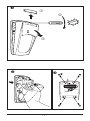
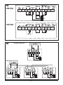
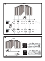
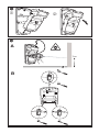
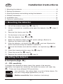
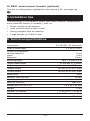
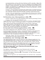
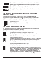
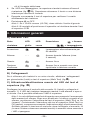
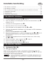
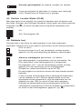
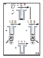
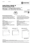
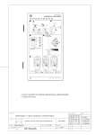
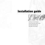
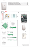
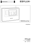
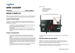
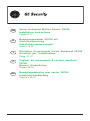
GB D I F NL Vector Enhanced Motion Sensor VE700 Installation Instructions Pages 8-13 Bewegungsmelder VE700 mit Vektorauswertung Installationsanweisungen Seiten 14-20 Rivelatore di movimento Vector Enhanced VE700 Istruzioni per l’installazione Pagg. 21-27 Capteur de mouvement à vecteur amélioré VE700 Manuel d’installation Pages 28-34 Bewegingsdetector met vector VE700 Installatie-handleiding Pagina’s 35-41 Click! 1 2 3 4 5 6 7 8 9 10 11 -1- VE735 VE736 Single device: Multiple device: 1 2 -2- 3 Detectors (ex-factory) 1 2 3 4 J1 6 7 1 2 ON -3- 9 10 11 3 4 8 COM port J3 CON 5 J2 VE700 J1 Low sensitivity J2 Medium sensitivity (ex-factory) J2 High sensitivity J2 -4- VE700 J1 Off (ex-factory) J2 J1 On J2 3 sec. 3 sec. a VE700 Left Day 3 -5- 1 2 ON B Night A ---- Alarm B Chime Alarm Day 4 A 1 2 ON 3 4 Right Night A Chime Alarm ---- Alarm B b c A 1m B -6- d e 20 m 60 m f g h -7- Installation Instructions GB 1. Mounting the detector .............................................................................. 8 2. Setting the detector ................................................................................. 8 3. Aligning the beam and walking testing the detector .............................. 10 4. General information ............................................................................... 11 5. Installation tips ....................................................................................... 13 6. Technical specifications ......................................................................... 13 1. Mounting the detector 1. Lift off the custom insert (fig. 2. Using a screwdriver, carefully prise open the detector (fig. and 3). , step 1). 3. Remove the interior part (fig. 4. Fix the base to the wall (fig. 5. Wire the detector (figs. 6. Select the desired jumper and DIP switch settings (Section 2). , steps 2 ). ). and ). 7. Replace the interior part (fig. b). 8. Align the detector, as shown (figs. c and i , and see Aligning the beam and walk testing the detector (section 3). 9. Remove the blinders and add the stickers, as required (figs. d and e) 10. Insert the insect-protection caps (fig. f, step 1). 11. Close the cover (fig. f, step 2). 12. Replace the custom insert (fig. f, step 3). 2. Setting the detector Jumpers (figs. ) J1 : PIR sensitivity It changes the distance-to-alarm delay (the speed of the decision algorithm); the higher the sensitivity, the faster the sensor will react (fig. ). There are three different PIR sensitivities. Low sensitivity: Use where there is a risk of false alarms. Do not use in long-range applications (>20 m). Medium sensitivity: Most situations (ex-factory) -8- High sensitivity: Use for high-risk situations. Recommended for use in corridors. J2 : Curtain Location Mode (CLM) It allows you to identify where the edges of the curtains are precisely located. When an intruder enters a curtain, the red and yellow LEDs flash alternatively (fig. 3). ). J2 is also used for long range alignment (see section Off On. See Section 3 B. J3 : Dual loop It is used to set the alarm and tamper relay. It allows you to connect the detector to any control panel. EOL Loop (4K7) Terminals 4 and 5 of the alarm output must be used when connecting to the control panel. Isolated Alarm and Tamper Loop (ex-factory) Tamper is isolated from the alarm relay. The EOL resistor in the tamper circuit is short-circuited. Terminals 3 and 4 of the alarm output must be used when connecting to the control panel. Dual Loop (only available on VE735) Tamper and alarm loop can be monitored over two wires. In a normal situation (no alarm) the Dual Loop impedance is 4K7. For a detector alarm, the alarm relay contact opens and the impedance of the Dual Loop increases to 9K4, indicating an alarm. When the detector housing is opened, the tamper circuit opens and the Dual Loop is interrupted, indicating a ). DIP switches (fig. ) (ex-factory) Table 1: DIP switches 1 2 ON 3 4 tamper alarm (fig. Function DIP switch On DIP switch Off 4. LEDs LEDs On LEDs Off 3. Chime direction Left-to-right Right-to-left 2. Chime Chime On Chime off 1. Polarity Active High Active Low -9- DIP switch 1: Control voltage (CV) On: “Active High” provides the standard Aritech logic with “Active High” logic to enable Walk test and Day/Night (Latch) inputs. Off: “Active Low” provides “Active Low” logic to enable Walk Test and Day/ Night (Latch) inputs. DIP switch 2: Chime (fig. ) The detector can distinguish the direction of the intruder during day time. Disable by setting the detector to Chime Off. When the chime is On, the detector will trigger an alarm when the intruder moves right-to-left or left-toright across the curtains. Note: If the Day/Night terminal is not used and the chime is On, the chime will be On both during arm and disarm (Day/Night) mode. DIP switch 3 : Chime direction (fig. ) On: Alarm when an intruder walks from left-to-right. Off: Alarm when an intruder walks from right-to-left. (Stand with your back to the detector to determine left and right directions.) DIP switch 4: LEDs On: Enables both LEDs on the detector at all times. Off: Puts both LEDs under the control of the Walk test and Armed/ Disarmed input when the system is disarmed. 3. Aligning the beam and walk testing the detector A) Using VE710 alignment tool: (fig. c) 1. Insert the VE710 in the sub-frame with the On/Off switch facing the floor. 2. Connect to the COM port. 3. Turn on the VE710. WARNING! Do not look into the laser beam. The VE710 laser is classifed by IEC60825-1 as a Class 2 laser. Consequently the output power is less than 1 mW. The eye’s blinking reflex is fast enough to prevent any permanet damage to the eye. 4. The laser spot indicates the product alignment (Fig. c A). If this spot on the wall veers from the centre of the desired detection area 1 m ) and from the ground, then loosen the base fixation screws (Fig. use the three adjustment screws in the base to realign it to the centre, as shown in Fig. c B. When the spot is correctly realigned, retighten the base fixation screws. 5. Remove the alignment tool and replace the cover. - 10 - 6. Carry out the walk test. Make sure that the red LED is On after the walk test. B) Without the alignment tool: (fig. i, back cover) 1. Insert the mirror blinders in order to ensure that the detector is in single-curtain mode. 2. Put J2 to on and wait until both LEDs are Off. 3. Walk in front of the detector across the field of view at normal speed (without pausing) and at some distance away (>10 m). When you enter the beam, both LEDs will start to blink simultaneously. After crossing the beam, if: 1. The red LED is on (fig. i A), the alignment is OK. 2. The red and yellow LEDs are blinking simultaneously then the field of view is obstructed and is insufficient to verify an alarm. There are two options: If the blinking started near the end of the detection area, you need to align the laser beam to the left (fig. i B). If the blinking started near the start of the detection area, you need to align the laser beam to the right (fig. i C). Loosen the base fixation screws (fig. ) and use the three adjustment screws in the base to realign the beam to the centre, as shown in fig. c B. When the beam is correctly realigned, retighten the base fixation screws. 4. If the LEDs do not blink, the curtain is outside of the detection range (fig.i D) . Walk across the beam at a shorter distance to try to detect it. 5. Redo the walk test to confirm that the detector is correctly aligned. 6. Put J2 to Off. Note 1: If the CLM is on, the Trouble output is activated. Note 2: It is advised to place the cover on the detector during the CLM walk test. 4. General information A) LED indication Detector Yellow Red status LED LED Power on Alarm Trouble High/Low voltage Description = On = Blinking Blinks alternatively for 50 sec. --- On during alarm period - nominally 3 sec. --- Continually On. On until correct voltage is restored. - 11 - B) Latching When using multiple detectors in a single loop, wire for Day/Night (Latch) . and Walk Test, as shown in figure C) Remotely enabling/disabling the walk test LED (fig. ) Disconnect the CV to terminal 10 (latch) and connect it to terminal 11. The detector’s LED will blink as the alarm relay opens and closes. The walk test can now be carried out. Note 1: Only enabling the walk test will not clear the alarm memory. After disarming the system following an alarm, switch the walk test to On. When you switch walk test to Off, the indication of memorised alarms will reappear. Only when CV is re-applied to terminal 10 (i.e., the system is rearmed) will the memory be cleared and the LEDs turned off. Note 2: To enable the walk test LED without a remote CV input, set DIP switch 4 to the on position. After the walk test, set DIP switch 4 to the off position. Note 3: We recommend that the detector is regularly walk tested and the communication with the control panel checked. D) Setting the Alarm Memory (fig. ) Note: First set the appropriate active Control Voltage (CV) using DIP switch 1. Connect the CV to terminal 10 when the system is armed. When the system is disarmed, disconnect the CV. If an alarm occurs during the armed period, a flashing red LED will indicate which the detector(s) caused the alarm. Re-applying the CV (re-arming the system) will reset the LED indication and memory. E) Selecting the coverage pattern (fig. e) The coverage pattern can be changed to fit specific requirements by using the mirror stickers (enclosed), as shown. It is recommended to blind unused curtains that are looking at walls or windows located very close to the detector. Caution: Removing the stickers can damage the mirror surface! F) Masking the curtains (fig. d) The mirror blinders are fitted ex-factory on the mirror. To remove a blinder, first remove the interior part of the detector. Then lift the lower part of the blinder and wiggle the upper part to loosen it. When long-range detection is not required (>20 m), remove the long-range mirror (fig. g). G) Pry-off and cover tamper The detector has both pry-off and cover tamper. It is important to use the screw indicated in figure in order to ensure pry-off tamper. For corner-mount applications, the pry-off tamper cannot be activated. - 12 - H) SB01 swivel-mount bracket (optional) Use this for ceiling-mount applications that require a 90° coverage (fig. h ). 5. Installation tips The technology in this detector resists false alarm hazards. Nevertheless avoid potential causes of instability, such as: Direct sunlight on the detector. Heat sources within a field of view. Strong draughts onto the detector. Large animals in a field of view. 6. Technical specifications Input power 9 to15 VDC (12 Vnominal) Peak-to-peak ripple 2 V (at 12 VDC) Current consumption: Normal operation Alarm Maximum 11 mA 9 mA 15 mA Mounting height Min. 1.8 max 3.0 m Target speed range 20 cm/sec to 3 m/sec Alarm output 80 mA at 30 VDC max. Tamper output 80 mA at 30 VDC max. Trouble output 80 mA at 30 VDC max. Alarm time 3 sec Detector start-up time 50 sec Operating temperature -10 °C to +55 °C Relative humidity Max. 95% Dimensions (H x W x D) 175 x 93 x 66 mm Weight 275 g Number of curtains 11 at 20 m + 1 at 60 m Viewing angle 86° at 20 m + 3° at 60 m IP/IK rating IP30 IK02 - 13 - D Installationsanweisungen 1. Befestigen des Melders ....................................................................... 14 2. Einstellen des Melders ......................................................................... 14 3. Ausrichtung des Erfassungsbereiches und Durchführung eines Gehtests für den Melder ...................................... 16 4. Allgemeine Informationen .................................................................... 18 5. Installationshinweise ............................................................................ 20 6. Technische Daten ................................................................................. 20 1. Befestigen des Melders 1. Nehmen Sie die individuelle Abdeckung ab (Abb. , Schritt 1). 2. Öffnen Sie vorsichtig mit einem Schraubendreher den Melder (Abb. Schritt 2 und 3). 3. Entnehmen Sie das Innenteil (Abb. 4. Befestigen Sie den Meldersockel an der Wand (Abb. ). und ). ). 5. Verdrahten Sie den Melder (Abb. 6. Wählen Sie die gewünschten Steckbrücken- und DIPSchaltereinstellungen aus (Abschnitt 2). 7. Setzen Sie das Innenteil wieder ein (Abb. b). 8. Richten Sie den Melder aus, wie in Abb. c und i dargestellt und beachten Sie die Hinweise für Ausrichtung des Erfassungsbereiches und Durchführung eines Gehtests für den Melder (Abschnitt 3). 9. Entfernen Sie die Spiegel-Abdeckungen, und bringen Sie die Aufkleber an (jeweils nach Bedarf, siehe Abbildungen d und e) 10. Setzen Sie die Insektenschutzkappen ein (Abb. f , Schritt 1). 11. Schließen Sie die Abdeckung (Abb. f , Schritt 2). 12. Setzen Sie die individuelle Abdeckung wieder ein (Abb. f, Schritt 3). 2. Einstellen des Melders Steckbrücken (Abb. ) J1: PIR-Empfindlichkeit Diese Option ändert die “Entfernung-zu-Alarm Verzögerung” (die Geschwindigkeit des Entscheidungs-Algorithmus); je höher die Empfindlichkeit, desto schneller reagiert der Melder (Abb. verfügt über drei unterschiedliche PIR-Empfindlichkeiten. - 14 - ). Der Melder , Geringe Empfindlichkeit: Verwenden Sie diese Einstellung, wenn ein Risiko für Falschalarme besteht. Verwenden Sie die Einstellung nicht bei Anwendungen mit großer Reichweite (>20 m). Mittlere Empfindlichkeit: In den meisten Fällen die richtige Einstellung (Werkseinstellung). Hohe Empfindlichkeit: Für Situationen mit besonders hohem Risiko geeignet. Empfohlen für Korridor-Anwendungen. J2: Vorhang-Lokalisierungs-Modus (CLM) Diese Funktion ermöglicht es Ihnen, präzise die Enden des Erfassungsvorhangs zu lokalisieren. Wenn eine eindringende Person einen Vorhang betritt, blinken die rote und die gelbe LED abwechselnd auf (Abb. ). J2 wird auch für für die Langstreckeneinstellung verwendet (siehe Abschnitt 3). Aus Ein. Siehe Abschnitt 3B. J3: Dual-MG Diese Funktion wir verwendet um das Alarm-und Sabotagerelais einzustellen. Sie ermöglicht die Anschaltung des Melders an jede konventionelle Einbruchmeldezentrale. Meldegruppen-Abschlusswiderstand (4K7) Die Anschlüsse 4 und 5 mit 4K7 Endwiderstand des Alarmausgangs können verwendet werden, wenn der Anschluss an einer Aritech-Einbruchmeldezentrale erfolgt. Getrennter Alarm- und Sabotageausgang (Werkseinstellung) Der Sabotageausgang ist vom Alarmrelais getrennt. Der Abschlusswiderstand in der Sabotageschaltung ist kurzgeschlossen. Die Anschlüsse 3 und 4 des Alarmausgangs müssen verwendet werden, wenn der Anschluss an eine konventionelle Einbruchmeldezentrale erfolgt. Dual-MG Ausgang (nur verfügbar bei VE735) Sabotage- und Alarmrelais können über zwei Drähte (Dual-MG) angeschaltet werden. Im Ruhezustand des Melders (kein Alarm) beträgt die DualMG-Impedanz 4K7. Bei einem Bewegungsalarm öffnet sich der Alarmrelaiskontakt, und die Impedanz der Dual-MG ändert sich auf 9K4 (Alarmzustand). Wenn das Meldergehäuse geöffnet wird, öffnet sich die Sabotageschaltung, und die Dual-MG wird unterbrochen, was einen Sabotagealarm verursacht (Abb. ). - 15 - DIP-Schalter (Abb. ) Tabelle 1: DIP-Schalter Funktion DIP-Schalter Ein DIP-Schalter Aus LEDs Ein LEDs Aus 3. Gongrichtung Links nach rechts Rechts nach links 2. Gong Gong ein Gong aus 1. Polarität Aktiv-High Aktiv-Low 1 2 ON 3 4 Werkseinstellung 4. LEDs DIP-Schalter 1: Steuerspannung (CV) Ein: “Aktiv-High” stellt der standardmäßigen Aritech-Logik die “Aktiv-High”Logik zur Verfügung, um die Eingänge für Gehtest und Scharf/Unscharf (Speicherung) zu ermöglichen. Aus: “Aktiv-Low” stellt “Aktiv-Low”-Logik zur Verfügung, um die Eingänge für Gehtest- und Scharf/Unscharf (Speicherung) zu ermöglichen. DIP-Schalter 2: Gong (Abb. ) Der Melder kann die Gehrichtung einer Person während der Tageszeit erkennen. Deaktivierung durch Einstellen des Melders auf Gong aus. Wenn die “Gong-Funktion” eingeschaltet ist, löst der Melder einen Alarm aus wenn eine eindringende Person von rechts-nach-links oder von links-nach-rechts durch den Erfassungsvorhang schreitet. Hinweis: Falls die Scharf/Unscharf -Anschlussklemme nicht beschaltet wird und die Gong-Funktion eingeschaltet ist, wird die Gong-Funktion im scharfen und unscharfen Zustand der EMA aktiviert. DIP-Schalter 3: Gongrichtung (Abb. ) Ein: Alarm, wenn eine Person von links nach rechts geht. Aus: Alarm, wenn eine Person von rechts nach links geht. (Stellen Sie sich mit dem Rücken zum Melder um die links und rechts Richtung festzulegen.) DIP-Schalter 4: LEDs Ein: Aktiviert ständig beide LEDs auf dem Detektor. Aus: Beide LEDs werden bei dieser Einstellung durch den Eingang für Gehtest und Scharf/Unscharf gesteuert, wenn das System unscharfgeschaltet ist. 3. Ausrichtung des Erfassungsbereiches und Durchführung eines Gehtests für den Melder A) Verwendung des VE710-Ausrichtungswerkzeuges: (Abb. c) 1. Führen Sie das VE710 in den Unterrahmen ein, wobei der Schalter On / Off in Richtung des Bodens zeigt. - 16 - 2. Schließen Sie es an den COM-Port an. 3. Schalten Sie das VE710 ein. WARNUNG! Schauen Sie nicht in den Laserstrahl. Der VE710 Laser ist durch die IEC60825-1 Norm als Klasse 2 Laser klassifiziert. Konsequenter Weise beträgt die Ausgangsleistung weniger als 1 mW. Unter normalen Umständen wird das menschliche Auge durch das reflexartige schnelle Blinzeln vor dauerhaften Schädigungen geschützt. 4. Der Laserpunkt gibt die Geräteausrichtung an (Abb c A). Wenn dieser Punkt auf der Wand vom Zentrum des gewünschten Überwachungsbereiches 1 m über den Boden abweicht, lösen Sie die ) und verwenden Befestigungsschrauben des Meldersockels (Abb. Sie zur Ausrichtung des Laserpunkts die drei Einstellschrauben wie in Abb. c B dargestellt. Nachdem der Laserpunkt korrekt eingestellt wurde, sind die Befestigungsschrauben des Meldersockels wieder festzuziehen. 5. Entfernen Sie das Ausrichtungswerkzeug, und setzen Sie die Abdeckung wieder ein. 6. Führen Sie den Gehtest durch. Stellen Sie sicher, dass die rote LED nach dem Gehtest eingeschaltet ist. B) Ohne das Ausrichtungswerkzeug: (Abb. i , rückseitige Abdeckung) 1. Setzen Sie die Spiegelabdeckungen ein, um sicherzustellen, dass sich der Melder im Ein-Vorhang-Modus befindet. 2. Stellen Sie J2 auf Ein, und warten Sie, bis beide LEDs aus sind. 3. Gehen Sie vor dem Melder quer durch den Erfassungsbereich mit normaler Geschwindigkeit (ohne Pausen) und in einem gewissen Abstand (>10 m). Wenn Sie in den Erfassungsbereich eintreten, beginnen beide LEDs, gleichzeitig zu blinken. Nachdem Sie den Erfassungsvorhang durchquert haben, gilt Folgendes: 1. Die rote LED ist EIN (Abb. i A): in diesem Fall ist die Ausrichtung OK. 2. Die rote und gelbe LED blinken gleichzeitig: in diesem Fall ist das Sichtfeld eingeschränkt und nicht ausreichend, um einen Alarm zu bestätigen. Es gibt zwei Optionen: Wenn das Blinken in der Nähe des Endes des Überwachungsbereichs begonnen hat, müssen Sie den Erfassungsvorhang nach links ausrichten (Abb. i B). Wenn das Blinken in der Nähe des Anfangs des Überwachungsbereichs begonnen hat, müssen Sie den Erfassungsvorhang nach rechts ausrichten (Abb. i C). Lösen Sie die Befestigungsschrauben des Meldersockels (Abb. - 17 - ) und verwenden Sie die drei Einstellschrauben, um den Erfassungsvorhang in das Zentrum wie in Abb. c B dargestellt einzurichten. Nachdem der Vorhang korrekt eingestellt wurde, ziehen Sie die Befestigungsschrauben des Meldersockels wieder fest. 4. Wenn die LEDs nicht blinken, befindet sich der Vorhang außerhalb des Überwachungsbereichs (Abb.i D). Gehen Sie in kürzerem Abstand quer durch den Vorhang, um die Erfassung nochmals zu testen. 5. Wiederholen Sie den Gehtest, um zu bestätigen, dass der Melder richtig ausgerichtet ist. 6. Stellen Sie J2 auf Aus. Hinweis 1: Wenn der CLM-Modus eingeschaltet, wird der Störungsausgang aktiviert. Hinweis 2: Es wird empfohlen, die Abdeckung auf den Melder aufzusetzen, während der CLM-Gehtest durchgeführt wird. 4. Allgemeine Informationen A) LED-Anzeige Melder Gelb Rot Status LED LED Störung = Ein = Blinkend Blinkt abwechselnd 50 Sek. lang. Spannung angelegt Alarm Beschreibung --- Während Alarmzeitraum nominal 3 Sek. --- Ständig ein. Über-/ Bis richtige Spannung Unterspannung wiederhergestellt ist B) Alarmspeicherung Wenn mehrere Melder in einer einzelnen Meldegruppe verwendet werden, verkabeln Sie die Melder für die Funktion Scharf/Unscharf (Speicherung) und Gehtest wie in Abbildung ‘ dargestellt (Abb. ). C) Aktivieren/Deaktivieren der Gehtest-LED von einem entfernten Standort (EMZ) aus (Abb. ) Trennen Sie die “CV-Steuerspannung” von Anschluss 10 (Speicherung), und legen Sie sie diese an den Anschluss 11 an. Die LED des Melders blinkt, wenn sich das Alarmrelais öffnet und schließt. Der Gehtest kann jetzt durchgeführt werden. Hinweis 1: Wenn Sie lediglich den Gehtest aktivieren, wird dadurch der Alarmspeicher nicht gelöscht. Wenn Sie das System nach einem Alarm - 18 - unscharfschalten, müssen Sie den Gehtest auf Ein schalten. Wenn Sie den Gehtest auf Aus schalten, wird eine Anzeige zu den gespeicherten Alarmen erneut erscheinen. Nur wenn das Scharf/Unscharf-Signal (CV) wieder an Anschluss 10 angelegt wird (das heißt, wenn das System wieder scharfgeschaltet wird), erfolgt ein Löschen des Speichers, und die LEDs werden ausgeschaltet. Hinweis 2: Um die Gehtest-LED ohne eine abgesetzte CV-Steuerspannung zu aktivieren, schalten Sie den DIP-Schalter 4 in die Position Ein. Schalten Sie nach dem Gehtest den DIP-Schalter 4 wieder in die Position Aus. Hinweis 3: Es wird empfohlen, in regelmäßigen Abständen einen Gehtest für den Melder durchzuführen und die Kommunikation mit der Einbruchmeldezentrale zu überprüfen. D) Einstellen des Alarmspeichers (Abb. ) Hinweis: Stellen Sie zuerst die geeignete aktive Steuerspannung (Control Voltage, “CV”) mit dem DIP-Schalter 1 ein. Legen Sie die CV an Anschluss 10 an, wenn das System scharfgeschaltet wird. Wenn das System unscharfgeschaltet ist, trennen Sie die CV wieder. Wenn während der Scharfschaltperiode ein Alarm auftritt, weist eine blinkende rote LED auf die Melder hin, die den Alarm ausgelöst haben. Wenn Sie die CV erneut anlegen (das System erneut scharfschalten), werden LED-Anzeige und Speicher zurückgesetzt. E) Auswahl des Erfassungsbereiches (Abb. e) Der Erfassungsbereich kann geändert werden, um spezifischen Anforderungen Rechnung zu tragen. Verwenden Sie hierzu wie gezeigt die Spiegelaufkleber (beigefügt). Es wird empfohlen, nicht verwendete Vorhänge abzudecken, die in Richtung von Wänden oder Fenstern zeigen, welche sich in der unmittelbaren Nähe des Melders befinden. Achtung: Wenn Sie die Aufkleber entfernen, kann dadurch die Spiegeloberfläche beschädigt werden! F) Abdecken der Vorhänge (Abb. d) Die Spiegelabdeckungen sind werkseitig auf dem Spiegel angebracht. Um eine Spiegelabdeckung zu entfernen, muss zunächst der Meldereinsatz aus dem Sockel entfernt werden. Heben Sie nachfolgend das untere Teil der Abdeckung an und lösen Sie die Abdeckung durch vorsichtiges Verwinden. Wenn eine Erfassung mit hoher Reichweite nicht erforderlich ist (>20 m), entfernen Sie den Spiegel für hohe Reichweite (Abb. g). G) Abreisskontakt und Gehäuse-Deckelkontakt zum Schutz vor Sabotage Der Melder verfügt sowohl über einen Abreisskontakt und einen Deckelkontakt zum Schutz vor Sabotage. Es ist wichtig, die mit markierte Schraube in Abbildung verwenden zu können. zu verwenden, um den Abreisskontakt Bei der Eckmontage kann der Abreisskontakt nicht aktiviert bzw. verwendet werden. - 19 - H) SB01 Dreh-Befestigungshalterung (optional) Verwenden Sie diese für Anwendungen bei Deckenmontage, bei denen eine Erfassung von 90° erforderlich ist (Abb. h). 5. Installationshinweise Die Technologie in diesem Melder dient zur Vermeidung falscher Alarmmeldungen. Dennoch sollten Sie potenzielle Instabilitätsfaktoren vermeiden, darunter: Direkte Einstrahlung von Sonnenlicht auf den Melder. Hitzequellen innerhalb des Erfassungsbereiches. Starke Zugluft am Melder. Große Tiere innerhalb des Erfassungsbereiches. 6. Technische Daten Versorgungsspannung 9 bis 15 V Gleichstrom (12 V nominal) Spitze/Spitze-Brummspannung 2 V (bei 12 V Gleichspannung) Stromaufnahme: Normalbetrieb Alarm maximal 11 mA 9 mA 15 mA Befestigungshöhe Min. 1,8 max 3,0 m Detektionsgeschwindikeit 20 cm/sek bis 3 m/sek Alarmausgang 80 mA bei 30 V Gleichspannung max. Sabotageausgang 80 mA bei 30 V Gleichspannung max. Störungsausgang 80 mA bei 30 V Gleichspannung max. Alarmdauer 3 sek Melder Aufwärmzeit 50 sek Betriebstemperatur -10 °C bis +55 °C Relative Luftfeuchtigkeit Max. 95% Abmessungen (H x B x T) 175 x 93 x 66 mm Gewicht 275 g Anzahl der Vorhänge 11 bei 20 m + 1 bei 60 m Erfassungswinkel 86° bei 20 m + 3° bei 60 m IP/IK-Einstufung IP30 IK02 VdS Nr: G 104XXX Klasse X - 20 - Istruzioni per l’installazione I 1. Montaggio del rivelatore ......................................................................... 21 2. Impostazione del rivelatore .................................................................... 21 3. Allineamento della tenda centrale e test di copertura del rivelatore ..... 24 4. Informazioni generali .............................................................................. 25 5. Consigli per l’installazione ...................................................................... 27 6. Specifiche tecniche ............................................................................... 27 1. Montaggio del rivelatore 1. Sollevare la chiusura a incastro (fig. 2. Aprire il rivelatore facendo leva con un cacciavite (fig. 3). , passo 1). 3. Rimuovere la parte interna (fig. 4. Fissare la base al muro (fig. 5. Collegare il rivelatore (fig. 6. Selezionare le impostazioni desiderate dei ponticelli e dei commutatori DIP switch (sezione 3). , passi 2 e ). ). e ). 7. Riposizionare la parte interna (fig. b). 8. Allineare il rivelatore come illustrato (fig. c e i) e consultare la sezione 4 Allineamento della tenda centrale e test di copertura del rivelatore. 9. Rimuovere la schermatura e applicare gli adesivi secondo necessità (fig. d e e). 10. Inserire i tappi di protezione dagli insetti (fig. f, passo 1). 11. Chiudere il coperchio (fig. f, passo 2). 12. Riposizionare la chiusura a incastro (fig. f, passo 3). 2. Impostazione del rivelatore Ponticelli (fig. ) J1: Sensibilità PIR Questa impostazione agisce sulle semitende da interessare per ottenere un allarme; più alta è la sensibilità, più veloce sarà la reazione del sensore (fig. ) Sono disponibili tre diverse sensibilità PIR. - 21 - Sensibilità bassa: da utilizzare quando vi è il rischio di falsi allarmi. Non utilizzare in applicazioni a lungo raggio (>20 m). Sensibilità media: per la maggior parte delle situazioni (impostazione di fabbrica). Sensibilità alta: per situazioni ad alto rischio. Raccomandata per l’utilizzo nei corridoi. J2: Modalità di individuazione posizione della tenda centrale (CLM) Questa funzione permette di identificare dove sono precisamente posizionati i margini della tenda. Quando un intruso entra in una tenda, i ). J2 è anche utilizzato per LED rosso e giallo lampeggiano (fig. l’allineamento della tenda centrale a lungo raggio (vedi sezione 3) Disattivata (OFF) Attivata (ON) (vedere la sezione 3B) J3: Doppio bilanciamento (fig. ) E’ utilizzato per impostare i relè di allarme e manomissione. Permette di collegare il rilevatore a qualsiasi centrale. Da utilizzare per l’impostazione dei relè di allarme e manomissione. Circuito con resistenza di fine linea singola (4K7) Per il collegamento del relè di allarme alla centrale utilizzare i morsetti 4 e 5 . Circuiti di allarme e antimanomissione isolati (impostazione di fabbrica) Il relè di manomissione è isolato dal relè di allarme. Il resistore di fine linea del circuito antimanomissione è cortocircuitato. Per il collegamento del relè di allarme alla centrale utilizzare i morsetti 3 e 4 . Doppio bilanciamento (solo su VE735) I circuiti di allarme e antimanomissione possono essere monitorati su due fili. In condizioni normali (nessun allarme) l’impedenza del circuito è 4K7. Nell’allarme del rivelatore, il contatto del relè di allarme si apre e l’impedenza del circuito sale a 9K4, indicando un allarme. Quando il contenitore del rivelatore viene aperto, il circuito antimanomissione si apre e il circuito viene interrotto, indicando così un allarme manomissione (fig. - 22 - ). ) Funzione DIP switch ON 1 2 Tabella 1: Commutatori DIP switch ON 3 4 Commutatori DIP switch (fig. Impostazione di fabbrica DIP switch OFF 4. LED LED accesi LED spenti 3. Direzione controllo giorno Da sinistra a destra Da destra a sinistra 2. Controllo giorno Controllo giorno attivato Controllo giorno disattivato 1. Polarità Attiva alta Attiva bassa Commutatore DIP switch 1: Tensione di controllo (CV) ON: “Attiva alta” fornisce la logica standard Aritech attiva alta che abilita gli ingressi test di copertura (Walk Test) e giorno/notte (Latch). OFF: “Attiva bassa” fornisce la logica attiva bassa che abilita gli ingressi test di copertura (Walk Test) e giorno/notte (Latch). Commutatore DIP switch 2: Controllo giorno (fig. a) Il rivelatore è in grado di distinguere la direzione di movimento dell’intruso durante il giorno. Per disattivare la funzione, impostare il rivelatore su Controllo giorno disattivato. Quando il controllo giorno è On, il rilevatore attiverà un allarme quando l’intruso si sposta da sinistra verso destra oppure da destra verso sinistra attraversando le tende. Nota: se l’ingresso giorno/notte non viene utilizzato e il controllo giorno è in On, il controllo giorno sarà attivo sia durante il periodo di inserimento che di disinserimento del sistema. Commutatore DIP switch 3: Direzione controllo giorno (fig. a) ON: l’allarme scatta quando l’intruso procede da sinistra a destra. OFF: l’allarme scatta quando l’intruso procede da destra a sinistra. (tenersi il rilevatore alle spalle per determinare la direzione da destra o da sinistra). Commutatore DIP switch 4: LED Acceso: attiva entrambi i LED del rivelatore in qualsiasi momento. Spento: mette entrambi i LED sotto il controllo degli ingressi test di copertura (Walk Test) e inserito/disinserito (Day/Night ) quando il sistema è disinserito. - 23 - 3. Allineamento della tenda centrale e test di copertura del rivelatore A) Con lo strumento di allineamento VE710: (fig. c) 1. Inserire il VE710 nell’apposito alloggiamento , con l’interruttore On/Off rivolto verso il pavimento. 2. Collegarlo alla porta COM. 3. Accendere il VE710. ATTENZIONE: Non guardare il raggio laser. Il VE710 è classificato dalle IEC60825-1 come laser di Classe 2. Di conseguenza la potenza di uscita è minore di 1 mW. Il riflesso incondizionato della palpebra dell’occhio è sufficientemente veloce per prevenire qualsiasi danno permanente all’occhio. 4. Il punto luminoso generato dal laser indica l’allineamento del prodotto (fig. c A). Se il punto luminoso sulla parete si discosta dal centro dell’area di rivelazione desiderata e da 1 m da terra, allentare le viti di ) e utilizzare le tre viti di regolazione poste fissaggio della base (fig. nella base per riallinearlo al centro (fig. c B). Quando il punto luminoso è correttamente allineato serrare le viti di fissaggio della base. 5. Rimuovere lo strumento di allineamento e riposizionare il coperchio. 6. Eseguire il test di copertura. Assicurarsi che il LED rosso sia acceso dopo il test di copertura. B) Senza lo strumento di allineamento: (fig. i, copertina posteriore) 1. Inserire gli schermi dello specchio per fare in modo che il rivelatore sia in modalità di copertura monofascio a tenda. 2. Portare J2 su ON e attendere che entrambi i LED si spengano. 3. Camminare davanti al rivelatore, attraverso il campo visivo, a velocità normale (senza fermarsi) e ad una certa distanza (>10 m). Entrando nel fascio, entrambi i LED iniziano a lampeggiare simultaneamente. Dopo aver attraversato il fascio: 1. Se il LED rosso è acceso (fig. i A), l’allineamento è corretto. 2. Se il LED giallo e quello rosso lampeggiano simultaneamente, il campo visivo è ostruito e non è sufficiente a verificare un allarme. Esistono due possibilità: e il lampeggiamento è iniziato verso la fine dell’area di rivelazione, è necessario allineare il sensore verso sinistra (fig. i B). Se il lampeggiamento è iniziato verso l’inizio dell’area di rivelazione, è necessario allineare il sensore verso destra (fig. i C). Allentare le viti di fissaggio della base (fig. ) e utilizzare le tre viti di regolazione poste nella base per riallinearlo al centro, come mostrato in fig. cB. Quando la tenda è correttamente riallineata serrare le - 24 - viti di fissaggio della base. 4. Se i LED non lampeggiano, la copertura a tenda è esterna all’area di rivelazione (fig. i D). Camminare attraverso il fascio a una distanza inferiore per cercare di rivelarla. 5. Eseguire nuovamente il test di copertura per verificare il corretto allineamento del rivelatore. 6. Posizionare J2 su OFF. Nota 1: Se il CLM è acceso (J2 ON), viene attivata l’uscita di guasto. Nota 2: Si consiglia di posizionare il coperchio sul rivelatore durante il test di copertura CLM. 4. Informazioni generali A) Indicatori LED Stato LED LED rivelatore giallo rosso Accensione Allarme Descrizione = Acceso = Lampeggiante Lampeggiano alternativamente per 50 secondi Acceso durante l’allarme (circa 3 secondi) --- Guasto Tensione alta/bassa --- Acceso fisso Acceso fino a quando non viene ripristinata la tensione corretta B) Collegamenti Se si utilizzano più rivelatori in un unico circuito, effettuare i collegamenti per giorno/notte (Latch) e test di copertura (Walk Test) (fig. ). C) Attivazione/disattivazione remota del LED del test di copertura (fig. ) Scollegare la tensione di controllo dal morsetto 10 (Latch) e collegarla al morsetto 11. Il LED del rivelatore lampeggia mentre il relè allarme si apre e si chiude. Ora è possibile effettuare il test di copertura. Nota 1: La sola abilitazione del test di copertura non comporta l’azzeramento della memoria di allarme. Dopo aver disattivato il sistema a seguito di un allarme, posizionare l’interruttore del test di copertura (Walk Test) su On (acceso). Posizionando l’interruttore del test di copertura (Walk Test) su Off (spento), compare nuovamente l’indicazione degli allarmi memorizzati. Soltanto quando la tensione di controllo viene ricollegata al morsetto 10 (ovvero il sistema viene nuovamente inserito) la memoria viene azzerata e i LED si spengono. - 25 - Nota 2: Per abilitare il LED del test di copertura senza un comando remoto della tensione di controllo, impostare il commutatore DIP switch 4 su ON (acceso). Dopo aver effettuato il test di copertura, impostare il commutatore DIP switch 4 su OFF (spento). Nota 3: Si consiglia di effettuare periodicamente test di copertura e controlli delle comunicazioni con la centrale. D) Impostazione della memoria di allarme (fig. ) Nota: Impostare innanzitutto la tensione di controllo attiva appropriata mediante il commutatore DIP switch 1. Collegare la tensione di controllo al morsetto 10 quando il sistema è inserito. Scollegare la tensione di controllo quando il sistema è disinserito. In caso di allarme con sistema inserito, un LED rosso lampeggiante indica quale dei rivelatori ha causato l’allarme. Collegando nuovamente la tensione di controllo (ovvero inserendo nuovamente il sistema), l’indicazione del LED e la memoria vengono azzerati. E) Selezione del campo di copertura (fig. e) È possibile modificare il campo di copertura per adattarlo a determinate esigenze utilizzando gli adesivi per gli specchi (forniti con il sensore), come illustrato. È opportuno schermare le tende non utilizzate rivolte verso pareti o finestre in prossimità del rivelatore. Attenzione: La rimozione degli adesivi potrebbe danneggiare la superficie dello specchio. F) Schermatura delle tende (fig. d) Gli schermi per lo specchio sono montati sullo specchio in fabbrica. Per rimuovere una maschera, per prima cosa rimuovere il corpo del rilevatore. Poi sollevare la parte bassa della maschera e tirare verso l’esterno per rimuoverla. Quando la rivelazione a lungo raggio non è necessaria (>20 m), rimuovere lo specchio a lungo raggio (fig. g). G) Protezione antirimozione e antimanomissione Il rivelatore è dotato di protezione antirimozione e antimanomissione. Per fissare correttamente la protezione antirimozione, è importante utilizzare la vite contrassegnata da un nella figura . Nelle applicazioni con installazione ad angolo, il tamper antirimozione non può essere attivato. Nota: per la conformità al II° livello delle norme CEI 79-2 è obbligatorio l’utilizzo della protezione antirimozione H) Supporto mobile SB01 (opzionale) Utilizzare il supporto per applicazioni con montaggio a soffitto che richiedano una copertura a 90° (fig. h). Nota: Il supporto mobile SB01 non è certificato IMQ-SISTEMI DI SICUREZZA. - 26 - 5. Consigli per l’installazione La tecnologia contenuta nel rivelatore è a prova di falsi allarmi. Tuttavia è opportuno evitare possibili fattori di instabilità, quali: Esposizione del rivelatore alla luce solare diretta. Fonti di calore all’interno del campo visivo. Forti correnti d’aria in prossimità del rivelatore. Animali di grossa taglia all’interno del campo visivo. 6. Specifiche tecniche Alimentazione 9 -15 V (12 V nominale) Ondulazione residua picco-picco 2 V (a 12 V ) Consumo di corrente: Funzionamento normale Massimo 11 mA 15 mA Altezza di montaggio Min 1,8 - max 3,0 m Gamma velocità bersaglio 20 cm/s - 3 m/s Uscita allarme 80 mA a 30 V max Uscita protez. antimanomissione. 80 mA a 30 V max Uscita guasto 80 mA a 30 V max Tempo di allarme 3 secondi Tempo di avvio rivelatore 50 secondi Temperatura di funzionamento Da -10°C a +55°C Certificata da +5°C a +40°C Umidità relativa Max 95% Dimensioni (A x L x P) 175 x 93 x 66 mm Peso 275 g Numero di tende 11 a 20 m + 1 a 60 m Angolo visivo 86° a 20 m + 3° a 60 m Gradi di protezione IP/IK IP30 IK02 Omologazione IMQ allarme I° & II° Livello solo VE735 Omologazione IMQ allarme VE735 (Per conformità alle norme CEI 79-2 per II° Livello l’utilizzo della protezione antirimozione è obbligatorio) - 27 - Manuel d’installation F 1. Montage du détecteur ............................................................................ 28 2. Réglage du détecteur ............................................................................ 28 3. Alignement du faisceau et test de marche du détecteur ...................... 31 4. Informations générales .......................................................................... 32 5. Avant d’installer ..................................................................................... 34 6. Spécifications techniques ...................................................................... 34 1. Montage du détecteur 1. Relevez l’insert personnalisé (figure 2. A l’aide d’un tournevis, ouvrez délicatement le détecteur en faisant 3. Retirez la partie interne (figure 4. Fixez la base au mur (figure 5. Raccordez le détecteur (figures 6. Sélectionnez le cavalier requis et la configuration des commutateurs DIP (paragraphe 2). levier (figure , étape 1). , étapes 2 et 3). ). ). et ). 7. Replacez la partie interne (figure b). 8. Alignez le détecteur, comme indiqué (figures c et if, et reportezvous à Alignement du faisceau et test de marche du détecteur (paragraphe 3). 9. Retirez les œillères et placez les autocollants (figures d et e). 10. Insérez les couvercles de protection contre les insectes (figure f, étape 1). 11. Refermez le couvercle (figure f, étape 2). 12. Refermez l’insert personnalisé (figure f, étape 3). 2. Réglage du détecteur Cavaliers (figure ) J1 : Sensibilité de l’IRP Le cavalier change la vitesse de l’algorithme de décision ; plus la sensibilité est élevée, plus le détecteur réagira vite (figure Il existe trois niveaux de sensibilité d’IRP. - 28 - ). Basse sensibilité : à utiliser dans les zones à risque de fausses alarmes. N’utilisez pas ce réglage pour les grandes distances (>20 m). Sensibilité moyenne : à utiliser dans la plupart des situations (en usine). Sensibilité haute : à utiliser dans les situations à haut risque, son utilisation est aussi recommandée dans des couloirs. J2 : Mode de Localisation de Rideau (MLR) Le cavalier permet de localiser précisément les bords des rideaux. Quand un intrus entre dans un rideau, les LEDs rouge et jaune s’allument alternativement. (Fig. 9). J2 est aussi utilisé pour l’alignement en longue portée (Voir paragraphe 3). Off (Désactivé) On (Activé). Voir la section 3B. J3 : Boucle double Utilisée pour régler le relais d’alarme et d’autoprotection, ce cavalier permet la connexion de ce détecteur avec toutes les centrales de détection. Boucle de fin de ligne (4K7) Les bornes 4 et 5 de la sortie d’alarme doivent être utilisées lors de l’établissement d’une connexion à la centrale. Boucle d’alarme et d’autoprotection isolée (en usine) L’autoprotection est isolée du relais de l’alarme. La résistance de fin de ligne dans le circuit d’autoprotection est courtcircuitée. Les bornes 3 et 4 de la sortie d’alarme doivent être utilisées lors de l’établissement d’une connexion à la centrale. Boucle double (disponible uniquement sur VE735) La boucle d’autoprotection et d’alarme peut être contrôlée via deux câbles. Dans une situation normale (pas d’alarme) l’impédance de la boucle double est de 4K7. Pour une alarme de détecteur, le contact de relais d’alarme s’ouvre et l’impédance de la boucle double augmente à 9K4, indiquant une alarme. Lorsque le boîtier du détecteur est ouvert, le circuit d’autoprotection s’ouvre et la boucle double est interrompue, indiquant une alarme d’autoprotection (figure - 29 - ). 4 ) (en usine) 1 2 ON 3 Commutateurs DIP (figure Tableau 1 : Commutateurs DIP Fonction Commutateur DIP On (Activé) Commutateur DIP Off (Désactivé) 4. Témoins lumineux Témoins lumineux On (Activés) Témoins lumineux Off (Désactivés) 3. Direction du carillon De gauche à droite De droite à gauche 2. Carillon Carillon On (Activé) Carillon Off (Désactivé) 1. Polarité Logique active haute Logique active basse Commutateur DIP n°1: Tension de contrôle (CV) On (Activé) : « Logique active haute » fournit la logique Aritech standard avec la logique active haute pour activer les entrées de test de marche et de jour/nuit (latch). Off (Désactivé) : « Logique active basse » fournit la logique active basse pour activer les entrées de test de marche et de jour/nuit (latch). Commutateur DIP n°2: Carillon (figure ) Le détecteur distingue la direction de l’intrus pendant le jour. Désactivez ce paramètre en réglant le carillon du détecteur sur Off (Désactivé). Quand le carillon est réglé sur On, le détecteur générera une alarme quand l’intrus ira de la gauche vers la droite (ou inversement selon la position du DIP n°3) à travers les faisceaux. Note : Si la borne jour/nuit est inutilisée, et que le carillon est sur on, alors le carillon sera sur on aussi bien durant l’armement que le désarmement (mode jour/nuit). Commutateur DIP n°3: Direction du carillon (figure ) On (Activé) : Alarme activée lorsqu’un intrus se déplace de la gauche vers la droite. Off (Désactivé) : Alarme activée lorsqu’un intrus se déplace de la droite vers la gauche. Se positionner le dos face au detecteur pour déterminer la gauche et la droite Commutateur DIP n°4: Témoins lumineux On (Activé) : Active les deux témoins lumineux du détecteur en permanence. Off (Désactivé) : Place les deux témoins lumineux sous le contrôle des entrées de test de marche et d’armement/désarmement lorsque le système est désarmé. - 30 - 3. Alignement du faisceau et test de marche du détecteur A) Avec l’outil d’alignement VE710 : (figure c ) 1. Insérez le VE710 dans le sous-cadre avec le commutateur orienté vers le bas. 2. Connectez-vous au port COM. 3. Allumez le VE710. AVERTISSEMENT ! Ne regardez pas directement dans le faisceau du laser. Le laser du VE710 est de classe 2 par l’IEC60825-1 ; en conséquence, la puissance de sortie du laser est de 1mW. Le réflexe de clignotement de l’œil sera suffisamment rapide pour éviter tout dommage irréversible à l’œil. 4. Le point du laser indique l’alignement du produit (figure c A). Si ce point sur le mur vire du centre de la zone de détection souhaitée (1 m ) à partir du sol), enlever les vis de fixation de la base (figure utilisez les trois vis de réglage de la base pour l’aligner de nouveau sur le centre, comme indiqué à la figure c B. Lorsque le spot est aligné correctement, replacer les vis de fixation de la base. 5. Retirez l’outil d’alignement et remettez en place le cache. 6. Effectuez le test de marche. Assurez-vous que le voyant lumineux est allumé après le test de marche. B) Sans l’outil d’alignement : (figure i, cache arrière) 1. Insérez les œillères du miroir pour assurer le fonctionnement du détecteur en mode rideau simple. 2. Allumez J2 et patientez jusqu’à l’extinction des voyants lumineux. 3. Déplacez-vous dans le champ de vue du détecteur, à une vitesse normale (sans pause), et à une distance d’environ 10 m. Lorsque vous entrez dans la zone du faisceau, les deux voyants lumineux clignotent simultanément. Après avoir traversé le faisceau, si : 1. Le voyant lumineux rouge est allumé (figure i A), l’alignement est correct. 2. Les voyants lumineux rouge et jaune clignotent simultanément, le champ de vue est obstrué et insuffisant pour vérifier l’alarme. Il existe deux possibilités : Si le clignotement a commencé près de la fin de la zone de détection, vous devez aligner le faisceau laser vers la gauche (figure i B). Si le clignotement a commencé près du début de la zone de détection, vous devez aligner le faisceau laser vers la droite (figure i C). Enlever les vis de fixation de la base (Fig. utiliser les 3 vis d’ajustement dans la vase pour réaligner le - 31 - ) et faisceau au centre, comme montré à la fig. c. Quand le faisceau est aligné correctement, replacer les vis de fixation de la base. 4. Si les voyants lumineux ne clignotent pas, le rideau est hors de la portée de détection (figure i D). Déplacez-vous dans le faisceau sur une distance plus courte pour le détecter. 5. Répétez le test pour confirmer l’alignement correct du détecteur. 6. Eteignez J2. Remarque 1 : si le CLM est allumé, la sortie de Perturbation est activée. Remarque 2 : il est conseillé de couvrir le détecteur pendant le test de marche du CLM. 4. Informations générales A) Indication des voyants lumineux Etat du Voyant Voyant détecteur lumineux jaune lumineux rouge Sous tension Alarme Description = On (Activé) = Clignotement Clignote alternativement pendant 50 secondes. --- Perturbation Allumé pendant la période d’alarme - 3 secondes. --- Toujours allumé. Tension Allumé jusqu’à restauration de haute/basse la tension correcte. B) Verrouillage Lorsque vous utilisez plusieurs détecteurs en boucle, câblez pour jour/nuit (latch) et test de marche, comme indiqué à la figure . C) Activation/désactivation distante du voyant lumineux de test de marche (figure ) Déconnectez la tension de contrôle de la borne 10 (latch) et connectez-la à la borne 11. Le voyant lumineux du détecteur clignote pendant que le relais d’alarme s’ouvre et se ferme. Vous pouvez maintenant effectuer le test de marche. Remarque 1 : l’activation du test de marche uniquement n’efface pas la mémoire. Après le désarmement du système à la suite d’une alarme, activez le test de marche. Lorsque vous désactivez le test de marche de nouveau, l’indication d’alarmes mémorisées réapparaît. La mémoire sera effacée et les voyants lumineux désactivés uniquement lorsque vous appliquerez la tension de contrôle de nouveau à la borne 10 (par exemple, le système est réarmé). - 32 - Remarque 2 : pour activer le voyant lumineux de test de marche sans une entrée de tension de contrôle distante, paramétrez le commutateur DIP 4 sur On (Activé). Après le test de marche, paramétrez le commutateur DIP 4 sur Off (Désactivé). Remarque 3 : il est conseillé d’effectuer régulièrement des tests de marche du détecteur et de vérifier la communication avec la centrale. D) Réglage de la mémoire d’alarme (figure ) Remarque : définissez tout d’abord la tension de contrôle (CV) correcte, à l’aide du commutateur DIP 1. Connectez la CV à la borne 10 lorsque le système est armé. Lorsque le système est désarmé, déconnectez la CV. Si une alarme se produit pendant la période armée, un voyant lumineux rouge clignotant indique le détecteur ayant déclenché l’alarme. Si vous appliquez la tension de contrôle de nouveau (en réarmant le système), vous réinitialisez l’indication de voyant lumineux et la mémoire. E) Sélection de la couverture (figure e) La couverture peut être modifiée pour répondre à des besoins spécifiques en utilisant les autocollants de miroir (fournis avec le détecteur), comme indiqué. Il est recommandé de masquer les rideaux non utilisés donnant sur des murs ou des fenêtres situés très près du détecteur. Attention! le retrait des autocollants risque d’endommager la surface des miroirs ! F) Masquage des rideaux (figure d) Les œillères de rideaux sont installées en usine sur le miroir. Lorsque la détection de grandes distances n’est pas requise (>20 m), retirez le miroir de grande distance (figure g). Pour supprimer un masque, lever la parte basse du masque et tortiller la partie supérieure pour le retirer. G) Autoprotection au retrait et du couvercle Le détecteur est équipé d’une autoprotection au retrait et du couvercle. Il est important d’utiliser la vis marquée protection au retrait. à la figure pour assurer la Pour des montages en angle, la protection à l’arrachement ne doit pas être activée. H) Patte de fixation à pivot SB01 (facultatif) Utilisez la patte de fixation à pivot pour les applications requérant une couverture de 90 ° (figure h). - 33 - 5. Conseils d’utilisation La technologie utilisée dans ce détecteur est conçue pour résister aux risques de fausses alarmes. Toutefois, il est conseillé d’éviter les causes d’instabilité potentielles, telles que : l’exposition du détecteur à la lumière directe ; les sources de chaleur dans le champ de vision ; les courants d’air puissants sur le détecteur ; la présence de grands animaux dans le champ de vision. 6. Spécifications techniques Puissance d’entrée 9 à 15 VCC (12 V nominal) Ondulation crête à crête 2 V (à 12 VCC) Consommation électrique : Fonctionnement normal Alarme Maximum 11 mA 9 mA 15 mA Hauteur de montage Min. 1,8 max 3 m Vitesse cible 20 cm/s à 3 m/s Sortie d’alarme 80 mA à 30 VCC max. Autoprotection 80 mA à 30 VCC max. Perturbation 80 mA à 30 VCC max. Temps d’alarme 3 secondes Temps de démarrage du détecteur 50 secondes Température de fonctionnement -10 °C à +55 °C Humidité relative 95 % max Dimensions (Hauteur x Largeur x Profondeur) Poids 175 x 93 x 66 mm 275 g Nombre de rideaux 11 à 20 m + 1 à 60 m Angle de visualisation 86 ° à 20 m + 3 ° à 60 m Classe IP/IK IP30 IK02 - 34 - Installatie-handleiding NL 1. De detector monteren ............................................................................ 35 2. De detector instellen .............................................................................. 35 3. De straalbundel uitlijnen en de looptest van de detector uitvoeren ...... 37 4. Algemene informatie .............................................................................. 38 5 Installatie tips ........................................................................................ 40 6. Technische specificaties ........................................................................ 40 1. De detector monteren 1. Til het afdekplaatje omhoog (fig. 2. Open de detector voorzichtig open met een schroevendraaier (fig. stappen 2 en 3). , stap 1). 3. Verwijder het binnengedeelte (fig. 4. Bevestig de basis aan de wand (fig. 5. Sluit de draden van de detector aan (fig. 6. Selecteer de gewenste instellingen voor de jumper en DIP-schakelaars (paragraaf 2). 7. Plaats het binnengedeelte terug (fig. b). 8. Regel het detectie bereik in, zoals is weergegeven (fig. c en i en zie De laser bundel uitlijnen en de looptest van de detector uitvoeren (paragraaf 3). 9. Verwijder de spiegelmaskers en breng de stickers aan, indien nodig (fig. i en e). , ). ). en ). 10. Plaats de plaatjes tegen insecten (fig. f , stap 1). 11. Plaats de deksel terug (fig. f, stap 2). 12. Plaats het afdekplaatje terug (fig. f, stap 3). 2. De detector instellen Jumpers (fig. ) J1: PIR-gevoeligheid Heeft invloed op de alarm situatie (de detectie snelheid algoritme) hoe hoger de gevoeligheid hoe sneller de detector reageert (fig. verschillende Detectie-gevoeligheden. ). Er zijn drie Lage gevoeligheid: te gebruiken in situaties met gevaar voor valse alarmen. Niet gebruiken in langeafstandstoepassingen (> 20 m). - 35 - Normale gevoeligheid: de meeste situaties (af fabriek). Hoge gevoeligheid: te gebruiken in situaties met verhoogd risico. Aanbevolen bij toepassing in gangen. J2: Curtain Locatie Mode (CLM) Met deze optie is het mogelijk om precies te bepalen waar de beams zich bevinden. Wanneer een indringer de beams inloopt gaan de rode en gele led knipperen (fig sectie3). ) J2 wordt ook gebruikt bij long beam applicaties (zie Uit Aan. Zie paragraaf 3B. J3: Dubbele lus) Hiermee stelt u het alarm en sabotagerelais in als twee weerstand applicatie. Hierdoor kunt u de detector aansluiten op alle inbraak panelen.. EOL-lus (4K7) De aansluitingen 4 en 5 van de detector moeten worden gebruikt voor de doorverbinding de detector aansluitingen. Alarm en sabotagelus gescheiden (af fabriek) Het sabotagerelais is gescheiden van het alarmrelais. De EOL-weerstand in het sabotagecircuit is kortgesloten. De uitgangen 4 en 7 van de alarmuitgang moeten worden gebruikt voor de aansluiting op het controlepaneel. Dubbele lus (alleen beschikbaar op de VE735) De sabotagelus en alarmlus kunnen met twee draden worden bewaakt. In een normale situatie (geen alarm) bedraagt de weerstand van de dubbele lus 4K7. Bij een detectoralarm wordt het alarmrelaiscontact geopend en stijgt de weerstand van de dubbele lus naar 9K4, en wordt zo een alarm gegeven. Wanneer de detectorbehuizing wordt geopend, wordt het sabotagecircuit geopend en wordt de dubbele lus onderbroken, en wordt zo een sabotagealarm gegeven (fig. - 36 - ). Tabel 1: DIP-schakelaars (af fabriek) 1 2 3 4 ) ON DIP-schakelaars (fig. Functie DIP-schakelaar Aan DIP-schakelaar Uit 4. LED’s LED’s Aan LED’s Uit 3. Looprichting Links naar rechts Rechts naar links 2. Deurbel Bel Aan Bel Uit 1. Polariteit Actieve hoog Actieve laag DIP-schakelaar 1: Controlespanning (CS) Aan: “Actief hoog” biedt de standaard Aritech-logica met “Actief hoog” om de ingangen ( Looptest) en (Dag/nacht (geheugen)) in te schakelen. Uit: “Actief laag” biedt “Actieve laag”-logica om de ingangen ( Looptest) en (Dag/nacht (geheugen)) in te schakelen. DIP-schakelaar 2: Deurbel (fig. ) Overdag kan de detector de richting van de indringer onderscheiden. U schakelt die functie uit door de detector in te stellen op Chime Off (Bel uit). Wanneer de deurbel functie aan staat zal de functie aangestuurd worden wanneer een indringer van links naar rechts loopt of van rechts naar links. Opmerking: Als de in/uit aansluiting niet wordt gebruikt en de deurbel functie staat aan dan gaat de deurbel bij in of uitgeschakeld systeem DIP-schakelaar 3: Deurbel richting (fig. ) Aan: Alarm wordt geactiveerd wanneer een indringer van links naar rechts loopt. Uit: Alarm wordt geactiveerd wanneer een indringer van rechts naar links loopt. (Met de rug naar de detector toe bepaalt wat de rechterzijde en linker zijde is). DIP-schakelaar 4: LED’s Aan: Beide LED’s op de detector blijven altijd ingeschakeld. Uit: Wanneer het systeem is uitgeschakeld, worden beide LED’s aangestuurd door de ingang (Looptest) en (In-/uitschakelen). 3. De Laserbundel uitlijnen en de looptest van de detector uitvoeren A) Met behulp van het VE710-uitlijningsgereedschap: (fig. c) 1. Plaats de VE710 in de geleiders, met de schakelaar Aan/Uit naar de grond gericht. 2. Sluit de connector aan op de ingang. - 37 - 3. Schakel de VE710 in. WAARSCHUWING! Kijk nooit recht in de laserstraal. De VE 700 laser is gekeurd volgens IEC60825-1 als een klasse 2 laser, het continue uitgangs vermogen van de laser is lager dan 1 mW. De oog reactie (knipperen) is snel genoeg om permanente beschadiging te voorkomen. 4. De laserstip geeft de afregeling van de detector aan (fig. c A). Als die stip op de wand afwijkt van het midden van het gewenste detectiegebied, gebruikt u de drie bijstelschroeven in de basis om het detectie gebied weer in het midden uit te lijnen, zoals in fig. c B is weergegeven. 5. Verwijder het uitlijningsgereedschap en plaats de deksel terug. 6. Voer de looptest uit. Controleer dat de rode LED AAN is gedurende de looptest. B) Zonderde laser unit: (fig. i, achterzijde) 1. Plaats de maskers voor spiegels zodat de detector zich in de mode single-curtain (met één gordijn) bevindt. 2. Plaats J2 op AAN positie en wacht tot beide LED’s uit zijn. 3. Loop op een kleine afstand (>10 m) met een normale snelheid door het detectieveld van de detector (zonder te stoppen). Wanneer u in de beam terechtkomt, beginnen beide LED’s gelijktijdig te knipperen. Als, nadat u door de straal bent gelopen: 1. de rode LED AAN is (fig. i A), is de afregeling geslaagd. 2. de rode en gele LED’s gelijktijdig knipperen, dan bevindt er zich een obstructie in het detectieveld en is het detectiebereik ontoereikend om een alarmsituatie te verifiëren. In dat geval zijn er twee mogelijkheden: Als het knipperen begon aan het einde van het detectiegebied, dient u de laserbundel meer naar links uit te lijnen (fig. i B). Als het knipperen begon aan het begin van het detectiegebied, dient u de laserbundel meer naar rechts uit te lijnen (fig. i C). Schroef in de basis eerst de montage schroeven (fig. ) los en gebruik de 3 afregeling schroeven in de basis om de beams in te regelen aangegeven in fig. c B. Wanneer de beams correct zijn ingeregeld schroef de montage schroeven weer vast. 4. Als de LED’s niet knipperen, bevindt het gordijn zich buiten het detectiebereik (fig. i D) . Loop op een kleinere afstand door het detectie bereik heen om te proberen het te detecteren. 5. Voer de looptest opnieuw uit om te controleren dat de detector nu juist is afgeregeld. 6. Plaats J2 op UIT positie. Opmerking 1: Als de Laser unit Aan is, is de storingsuitgang geactiveerd. Opmerking 2: Het verdient aanbeveling de deksel van detector te plaatsen - 38 - voordat u de CLM-looptest uitvoert. 4. Algemene informatie A) LED-indicatie Detector- Gele Rode status LED LED Op spanning sec. Alarm Beschrijving = Aan = Knipperend Knipperen afwisselend gedurende 50 --- Storing Stuur spanning Aan tijdens alarmperiode - normaal 3 sec. --- Continu aan. Aan tot de juiste spanning is hersteld. B) In geheugen Bij het gebruik van meerdere detectors in een enkelvoudige lus, bedraadt u voor (Dag/nacht (geheugen)) en (Looptest), zoals in figuur weergegeven. is C) De looptest-LED op afstand in-/uitschakelen (fig. ) Koppel de “Aansturing” los van de klem10 (geheugen) en sluit deze aan op aansluiting 11. De LED van de detector zal knipperen wanneer het alarmrelais wordt geopend en gesloten. De looptest kan nu worden uitgevoerd. Opmerking 1: Het alarmgeheugen wordt niet gewist door alleen de looptest in te schakelen. Wanneer u na een alarm het systeem uitschakelt, moet u de looptest op Aan instellen. Wanneer u de looptest op Uit instelt, zal de indicatie van de in het geheugen opgeslagen alarmen opnieuw verschijnen. Pas nadat de Ansturing opnieuw op aansluiting 10 is aangesloten (lees: nadat het systeem opnieuw is ingeschakeld), zal het geheugen worden gewist en zullen de LED’s niet branden. Opmerking 2: Als u de looptest-LED wilt inschakelen zonder een Aansturingingang op afstand, stelt u DIP-schakelaar 4 in op de Aan-stand. Na de looptest stelt u DIP-schakelaar 4 in op de Uit-stand. Opmerking 3: Het verdient aanbeveling regelmatig de looptest van de detector uit te voeren en de communicatie met het controlepaneel te controleren. D) Het alarmgeheugen instellen (fig. ) Opmerking: Stel eerst de juiste actieve Controlespanning (“Aansturing) in met DIP-schakelaar 1. - 39 - Sluit de Aansturing aan op aansluiting 10 wanneer het systeem is ingeschakeld. Wanneer het systeem is uitgeschakeld, koppelt u de Aansturing los. Als in de ingeschakelde periode een alarm wordt geactiveerd, geeft een knipperende rode LED aan welke detectors het alarm hebben veroorzaakt. Wanneer u de Aansturing weer aansluit (lees: het systeem opnieuw inschakelt), worden de LED-indicatie en het geheugen weer op de beginwaarden ingesteld. E) Het dekkingspatroon selecteren (fig. e) Het dekkingspatroon kan aan specifieke vereisten worden aangepast met behulp van de spiegelstickers (Toegevoegd), zoals is weergegeven. Het verdient aanbeveling niet-gebruikte gordijnen die gericht zijn naar wanden of vensters die zich dicht bij de detector te bevinden, te maskeren. Let op: Bij het verwijderen van de stickers kunt u het spiegeloppervlak beschadigen! F) De gordijnen maskeren (fig. d) De spiegelmaskers zijn in de fabriek op de spiegel bevestigd. Om de Spiegel maskers te verwijderen moet eerst het binnenste deel van de detector verwijderd worden. Til het onderste deel van het masker op en beweeg met het masker zodat deze verwijderd kan worden. Wanneer langeafstandsdetectie (>20 m) niet vereist is, verwijdert u de langeafstandsspiegel (fig. g). G) Afneem- en dekselsabotagebeveiliging De detector is uitgerust met een afneem- en dekselsabotagebeveiliging. Om de afneemsabotagebeveiliging mogelijk te maken, moet de schroef die in figuur met - is gemarkeerd, worden bevestigd. Bij hoekmontage kan de afneem sabotage beveiliging niet gebruikt worden H) SB01-montage beugel (optioneel) Wordt gebruikt voor plafondmontage in situaties waar een dekking van 90° is vereist (fig. h). 5. Voordat u aan de installatie begint De technologie in deze detector is bestand tegen de oorzaken van valse alarmen. Vermijd niettemin alle mogelijke oorzaken van instabiliteit, zoals: Rechtstreeks zonlicht op de detector. Hittebronnen in het detectieveld. Veel tocht op de detector. Grote dieren in het detectieveld. - 40 - 6. Technische specificaties Aansluitspanning 9 tot 15 Vdc (12 V nominaal) Max rimpelspanning 2 V (bij 12 Vdc) Stroomverbruik: Normale werking Alarm Maximum 11 mA 9 mA 15 mA Montagehoogte Min. 1,8 - Max 3,0 m Bewegingssnelheid 20 cm/sec. tot 3 m/sec. Alarmuitgang 80 mA bij 30 Vdc max. Sabotage-uitgang 80 mA bij 30 Vdc max. Storingsuitgang 80 mA bij 30 Vdc max. Alarm tijd 3 sec. Opstarttijd detector 50 sec. Werkingstemperatuur -10 °C tot +55 °C Relatieve vochtigheid Max. 95% Afmetingen (H x B x D) 175 x 93 x 66 mm Gewicht 275 g Aantal zones 11 bij 20 m + 1 bij 60 m Detectiegebied 86° bij 20 m + 3° bij 60 m IP/IK-klasse IP30 IK02 - 41 - i A 60 m VE700 B C VE700 VE700 D VE700 © 2004 GE Security BV. All rights reserved. 5797-1A