1
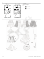
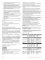
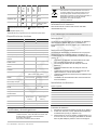
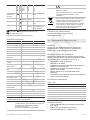
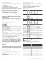
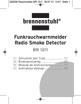
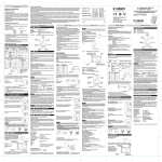
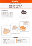
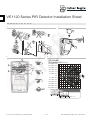
VE1120 Series PIR Detector Installation Sheet
EN DE ES FR
IT
NL
PL
PT
SV
2
1
1
2
3
3
4
VE1120(AM)
20 m range (65 ft. 7 in.)
12 m (39 ft. 4 in.)
10 m (32 ft. 9 in.)
8 m (26 ft. 2 in.)
6 m (19 ft. 8 in.)
4 m (13 ft. 1 in.)
2 m (6 ft. 6 in.)
0m
2 m (6 ft. 6 in.)
4 m (13 ft. 1 in.)
6 m (19 ft. 8 in.)
8 m (26 ft. 2 in.)
10 m (32 ft. 9 in.)
12 m (39 ft. 4 in.)
4
m
(optimum) 2.4 m
(7 ft. 10 in.)
1.2 m (3 ft. 11 in.)
4 m (13 ft. 1 in.)
20.0 m (65 ft. 7 in.)
© 2011 UTC Fire & Security. All rights reserved.
1 / 20
P/N 146279999-5 • REV 00.01 • ISS 29JUL11
5
VE1120
VE1120AM
J1: Not used
J3 and J4: See Figure 7.
J6:
J4
J3
J4
J3
CV + polarity
CV – polarity
J6
J1
J6
J1
6
2 / 20
P/N 146279999-5 • REV 00.01 • ISS 29JUL11
CP
Zone Y
11
1
2
3
4
5
6
7
8
9
11
J3
10
J4
1
2
3
4
5
6
7
8
9
Normal 4.7 kΩ
9.4 kΩ
Alarm
Tamper
0Ω
Short
AM/TF
10
GND
+12V
Alarm
Alarm
Tamper
Tamper
WT
D/N
AM
AM
Rtest
J3
GND
+12V
Alarm
Alarm
Tamper
Tamper
WT
D/N
AM
AM
Rtest
11
10
GND
+12V
Alarm
Alarm
Tamper
Tamper
WT
D/N
AM
AM
Rtest
1
2
3
4
5
6
7
8
9
J4
CP
8
1
2
3
4
5
6
7
8
J3
J4
GND
+12V
Alarm
Alarm
Tamper
Tamper
WT
D/N
AM
AM
Rtest
GND
+12V
Alarm
Alarm
Tamper
Tamper
WT
D/N
8
8
Zone X
J4
J3
J4
Zone Y
GND
+12V
Alarm
Alarm
Tamper
Tamper
WT
D/N
CP
GND
+12V
Alarm
Alarm
Tamper
Tamper
WT
D/N
J3
1
2
3
4
5
6
7
8
GND
+12V
Alarm
Alarm
Tamper
Tamper
WT
D/N
J4
1
2
3
4
5
6
7
8
VE1120AM
J3
Normal 4.7 kΩ
9.4 kΩ
Alarm
Tamper
0Ω
Short
Zone X
8
Zone X
8
Normal < 33 Ω
Alarm
VE1120
J4
11
CP
Normal < 33 Ω
Alarm
2
10
J3
J3
1
2
3
4
5
6
7
8
9
J4
Zone X
J4
VE1120AM
GND
+12V
Alarm
Alarm
Tamper
Tamper
WT
D/N
VE1120
1
2
3
4
5
6
7
8
1
GND
+12V
Alarm
Alarm
Tamper
Tamper
WT
D/N
AM
AM
Rtest
7
J4
Zone Y
8
8
Normal 4.7 kΩ
9.4 kΩ
Alarm
Tamper
Short
0Ω
AM/TF
Zone X
CP
Zone X
8
Normal 4.7 kΩ
9.4 kΩ
Alarm
Tamper
Short
0Ω
11
J3
10
1
2
3
4
5
6
7
8
9
1
2
3
4
5
6
7
8
J3
EN: Installation Sheet
Introduction
•
Installing two detectors facing each other and less than
50 cm (20 in.) apart (only AM detectors)
Installing the detector
The VE1120 series includes the VE1120 PIR and VE1120AM
PIR-AM motion sensors. They have a patented mirror, pyro,
and signal processing technology.
Figure 7 legend
Note: VE1120AM has not been evaluated by UL/cUL.
Installation guidelines
The technology used in these detectors resists false alarm
hazards. However, avoid potential causes of instability (see
Figure 1) such as:
•
•
•
•
•
•
Direct sunlight on the detector
Strong draughts onto the detector
Heat sources within the detector field of view
Animals within the detector field of view
Obscuring the detector field of view with large objects,
such as furniture
Objects within 50 cm (20 in.) of the anti-masking (AM)
detector
P/N 146279999-5 • REV 00.01 • ISS 29JUL11
Item
Description
1.
Standard connection (factory default)
2.
Dual loop connection
CP
Control panel
WT
Walk test
AM
Antimasking
D/N
Day/night
Rtest
Remote test
To install the detector:
1.
2.
3.
Lift off the custom insert and remove the screw
(see Figure 2, step 1).
Using a screwdriver, carefully prise open the detector (see
Figure 2, steps 2 and 3).
Fix the base to the wall between 1.8 and 3.0 m (5.9 and
9.8 ft.) from the floor. For flat mounting use a minimum of
3 / 20
4.
5.
6.
7.
8.
9.
two screws (DIN 7998) in positions A. For corner-mounting
use screws in positions B or C (Figure 3). To install a pryoff tamper, use position A or C.
Note: Using the pry-off tamper has not been evaluated by
UL/cUL.
Wire the detector (see Figures 3 and 7).
UL/cUL installations: All wiring must be made according
to National Electrical Code, NFPA70, and CSA C72.1,
Canadian Electrical Code Part I, Safety Standards for
Electrical Installations.
Select the desired jumper and DIP switch settings (see
Figure 5). See “Jumper settings” below for more
information.
Remove the blinders and add the stickers, if required (see
Figure 6 for an example).
For ceiling-mount applications that require a 90° coverage
use the SB01 swivel-mount bracket.
Note: Using the swivel-mount bracket has not been
evaluated by UL/cUL. Ceiling mount application has not
been evaluated by UL/cUL.
Close the cover.
Insert the screw and place the custom insert.
•
Controls the AM relay functionality during the NIGHT
mode together with SW1.
The WT input controls the LED functionality together with the
D/N input.
When the detector is in the Day mode and Walk Test On
mode, the LEDs of the detector can be activated. See “LED
indication” below for more information.
During the Night mode the LEDs are always switched off.
If a PIR intruder alarm if detected in the Night mode and the
detector switches back to Day mode, the red LED starts
flashing to indicate an alarm in memory.
The alarm memory is reset by switching the detector to Night
mode.
DIP switch settings
Factory default:
5
4
3
2
1
ON
For EN 50131 Grade 3 installations, do not use mounting
position B.
SW 1: When to signal AM (anti-masking) or TF (technical
fault) output
Jumper settings
On: Signals AM or TF only when the system is in Day mode
(factory default).
See Figure 5 for the jumper locations in the detector.
Off: Always signals AM or TF during Day and Night mode.
J1: Not used
SW 2: AM sensitivity
J3 and J4: Dual loop setting
On: Selects a higher level of AM sensitivity. AM relay reacts
within 6 seconds.
This sets the alarm and tamper relays. It allows you to connect
the detector to any control panel. Use jumpers 3 and 4. See
Figure 7.
Use Remote Test (RT) to test the detector from the control
panel. The detector will activate the Alarm relay if the test
result is positive, and the AM relay if the test result is negative.
J6: Polarity setting of the control voltage (CV)
On (factory default):
•
•
•
•
The detector is in Day mode (system disarmed) when the
D/N input is connected to GND (terminal 1)
The detector is in Night mode (system armed) when the
D/N input is connected to +12 V (terminal 2)
The detector is in Walk Test Off mode (LEDs are disabled)
when the WT input is connected to GND (terminal 1)
The detector is on Walk Test On mode (LEDs are
enabled) when the WT input is connected to +12 V
(terminal 2)
Off:
•
•
•
•
The detector is in Day mode (system disarmed) when the
D/N input is connected to +12 V (screw terminal 2).
The detector is in Night mode (system armed) when the
D/N input is connected to GND (terminal 1).
The detector is in Walk Test Off mode (LEDs are disabled)
when the WT input is connected to +12 V (terminal 2).
The detector is on Walk Test On mode (LEDs are
enabled) when the WT input is connected to GND
(terminal 1).
Off: Selects the standard AM sensitivity. AM relay reacts within
12 seconds (factory default).
SW 3: Resetting the AM/TF output
The system will only reset an AM alarm if it has ensured that
the cause of the AM alarm has been removed. If the AM
circuitry cannot return to its original reference levels, then
either the detector is still masked or possibly has been
damaged. The owner should then visually check that the
detector is still fully functional.
On: Resets the AM or TF status 40 seconds after a PIR alarm.
Off: Resets the AM or TF status after a PIR alarm when the
system is in Day and Walk Test mode. The yellow LED will
blink quickly. When the system is in Night status, the yellow
LED will turn off and the system is reset (factory default).
SW 4: Signaling AM or TF output
On: Signals AM on both the AM and Alarm relays. Signals TF
on the AM relay only (EN 50131).
Off: Signals AM and TF on the AM relay (factory default).
SW 5: Setting LEDs
On: Enables both LEDs on the detector at all times (factory
default).
Off: Puts both LEDs under the control of the Walk Test and
Day/Night input. This activates the memory feature of the
detector.
D/N and WT functionality
LED indication
The D/N input:
PIR
•
•
Start up
Controls the LED functionality together with the WT input.
Resets the alarm memory
4 / 20
Red
LED
Yellow
LED
Alarm
relay
Closed
AM
relay
To reset
Automatically
after 25 s
P/N 146279999-5 • REV 00.01 • ISS 29JUL11
Low voltage
Open
(Alarm)
Apply correct
voltage
PIR intruder
alarm
Open
(Alarm)
Automatically
after 3 s
PIR/AM
Red
LED
Yellow
LED
Alarm
relay
AM
relay
To reset
Start up
Closed
Closed
Automatically
after 60 s
Low voltage
Open
(Alarm)
Open
(Alarm)
Apply correct
voltage
PIR intruder
alarm
Open
(Alarm)
Switch to Night
mode
Open*
(Alarm)
Open
(Alarm)
After AM
reset
See DIP
switch 3
Open
(Alarm)
VE1120AM
95% max. noncondensing
(UL/cUL Installations)
Weight
150 g
IP/IK rating
IP30 IK02
Regulatory information
Manufacturer
UTC Fire & Security Americas Corporation, Inc.
1275 Red Fox Rd., Arden Hills, MN 55112-6943, USA
Authorized EU manufacturing representative:
UTC Fire & Security B.V.
Kelvinstraat 7, 6003 DH Weert, Netherlands
Certification
UL/cUL
Switch to Night
mode
Technical
fault
Continuously on
Relative humidity
Automatically
after 3 s
Latched PIR
(Memory)
AM alarm
VE1120
The product must be connected to a listed burglar
system compatible control unit or power supply unit,
which provides a minimum 4 hours of standby power
and has a voltage output between 10 and 15 VDC.
All wiring must be made according to National
Electrical Code, NFPA70, and CSA C22.1, Canadian
Electrical Code Part I, Safety Standards for Electrical
Installations.
Do a successful
walk test
Normal blinking (1 Hz)
Perform walk test at least one per year.
Use only a listed power-limited supply.
Fast blinking (4 Hz)
* Depends on the setting of the DIP switch SW4.
VE1120AM has not been evaluated by UL/cUL.
Specifications
2002/96/EC (WEEE directive): Products marked with
this symbol cannot be disposed of as unsorted
municipal waste in the European Union. For proper
recycling, return this product to your local supplier
upon the purchase of equivalent new equipment, or
dispose of it at designated collection points. For more
information see: www.recyclethis.info.
VE1120
Detector
VE1120AM
PIR
PIR with AM
Signal processing
V2E
Range
20 m
Optical
11 high-density mirror curtains
Memory
Yes
Input power
For UL/cUL installations
9 to 15 VDC (12 V nominal)
10 to 15 VDC (12 V nominal)
Peak-to-peak ripple
Detector start-up time
For contact information see our Web site:
utcfireandsecurity.com.
2 V (at 12 VDC)
25 s
60 s
Normal current
For UL/cUL installations
6.5 mA
0.078 W
10 mA
—
Current in alarm
1.2 mA
3.8 mA
Maximum current
(LED on)
11 mA
24 mA
Mounting height
Contact information
1.8 to 3.0 m (5.9 ft.to 9.8 ft.)
DE: Installationsanweisungen
Einführung
Die Serie VE1120-D/VE1120AM-D besteht aus PIR/PIR-AMBewegungsmeldern. Letztere verfügen über einen patentierten
Spiegel sowie Pyro- und Signalverarbeitungstechnologie.
Dead zones
0.9 m (3 ft.) at minimum mounting height
1.5 m (5 ft.) at maximum mounting height
Installationsanleitungen
Target speed range
30 cm/s to 3 m/s
(1 ft./s to 10 ft./s)
20 cm/s to 3 m/s
(0.65 ft./s to 10 ft./s)
Alarm (NC) / Tamper
relay characteristic
80 mA, 30 VDC,
resistive
80 mA, 30 VDC
Die in diesen Meldern eingesetzte Technologie dient zur
Vermeidung falscher Alarmmeldungen. Dennoch sollten Sie
potenzielle Instabilitätsfaktoren vermeiden (Abb. 1), darunter:
Pry-off tamper (not
evaluated by UL/cUL)
Optional
Onboard (yes)
AM relay characteristic
—
80 mA
at 30 VDC max.
PIR Alarm time
Operating temperature
For UL/cUL installations
Dimensions (H x W x D)
•
•
•
•
•
3s
•
−10 to +55°C (14 to 130°F)
0 to 49°C ( 32 to 120°F )
•
125 × 55 × 60 mm
(4.92 x 2.16 x
2.36 in.)
P/N 146279999-5 • REV 00.01 • ISS 29JUL11
125 × 65 × 60 mm
(4.92 x 2.6 x 2.36 in.)
Direkte Sonneneinstrahlung auf den Melder
Starke auf den Melder gerichtete Zugluft
Hitzequellen innerhalb des Erfassungsbereichs
Tiere innerhalb des Erfassungsbereichs des Melders
Verdecken des Erfassungsbereichs des Melders durch
große Objekte, z. B Möbel
Objekte innerhalb von 50 cm des Melders mit
Abdeckerkennung (AM)
Montage zweier gegenüberliegender Melder in einem
Abstand von weniger als 50 cm
5 / 20
Installation des Melders
DIP-Schaltereinstellung
Abbildung 7 Positionen
Werkseinstellung:
Position
Beschreibung
1.
Standard Anschaltung (Werkseinstellung)
2.
Dual-MG Anschaltung
CP
Einbruchmeldezentrale
WT
Gehtest
AM
Abdeckerkennung
D/N
Scharf/Unscharf
Rtest
Ferntest
5
4
3
2
1
ON
SW 1: Wann eine Abdeckungs(AM)- oder Technischer
Fehler(TF)-Ausgabe signalisiert werden sollte
Ein: Signalisiert AM oder TF nur, wenn sich das System im
Tagbetrieb (unscharf) befindet (Werkseinstellung).
Aus: Signalisiert AM oder TF immer im Scharf- und
Unscharfbetrieb.
SW 2: AM-Empfindlichkeit
Installation des Melders:
1.
2.
3.
4.
5.
6.
7.
8.
9.
Nehmen Sie die kundenspezifische Abdeckkappe ab und
entfernen Sie die Schraube (Abb. 2, Schritt 1).
Öffnen Sie den Melder vorsichtig mit einem
Schraubendreher (Abb. 2, Schritte 2 und 3).
Befestigen Sie die Basis in einem Abstand von 1,80 m bis
3 m vom Boden an der Wand. Verwenden Sie bei der
Wandmontage mindestens 2 Schrauben (DIN 7998) in den
Positionen A. Verwenden Sie für eine Eckmontage
Schrauben in den Positionen B oder C (Abb. 3). Bei
Installation eines Abreißkontakts, verwenden Sie die
Positionen A oder C.
Verkabeln Sie den Melder (Abb. 3 und 7).
Wählen Sie die gewünschten Steckbrücken- und DIPSchaltereinstellungen aus (Abb. 5). Weitere Informationen
finden Sie im Abschnitt „Steckbrückeneinstellungen“.
Entfernen Sie die Spiegel-Abdeckungen und bringen Sie
bei Bedarf die Aufkleber an (Abb. 6 enthält ein Beispiel)
Verwenden Sie für Deckenmontagen, bei der eine
Überwachung von 90° erforderlich ist, den
Befestigungssatz für Wand- und Deckenmontagen (SB01).
Schließen Sie die Abdeckung.
Setzen Sie die Schraube und die kundenspezifische
Abdeckkappe wieder ein.
Ein: Wählt eine höhere Stufe der Abdeckungsempfindlichkeit
aus. AM-Relais reagiert innerhalb von 6 Sekunden.
Aus: Wählt die Standard-Abdeckungsempfindlichkeit aus. AMRelais reagiert innerhalb von 12 Sekunden (Werkseinstellung).
SW 3: Zurücksetzen des AM/TF-Ausgangs
Das System setzt einen AM-Alarm nur zurück, wenn
sichergestellt ist, dass die Ursache des AM-Alarms behoben
wurde. Wenn der AM-Schaltkreis nicht zu seiner
ursprünglichen Referenzebene zurückkehren kann, ist
entweder der Melder noch abgedeckt oder wurde
möglicherweise beschädigt. Der Betreiber sollte dann
nachschauen, ob der Melder noch voll funktionsfähig ist.
Ein: Setzt den AM- oder TF-Status 40 Sekunden nach einem
PIR-Alarm zurück.
Aus: Setzt den AM- oder TF-Status nach einem PIR-Alarm
zurück, wenn das System in den Unscharf- und GehtestModus geschaltet wurde. Die gelbe LED wird schnell blinken.
Wenn sich das System im Scharfmodus befindet, erlischt die
gelbe LED-Anzeige und das System wird zurückgesetzt
(Werkseinstellung).
SW 4: Signalisiert AM- oder TF-Ausgang
Bei EN50131 Grad 3 Installationen darf die Montageposition B
nicht verwendet werden.
Ein: Signalisiert AM (Abdeckung) auf dem AM- und auf dem
Alarmrelais. Signalisiert TF nur auf dem AM-Relais
(EN 50131).
Steckbrückeneinstellungen
Aus: Signalisiert AM und TF auf dem AM-Relais
(Werkseinstellung).
Siehe Abbildung 5 für die Steckbrückenpositionen (J1-6) im
Melder.
J1: Nicht verwendet
J3 und J4: Einstellung für Dual-Meldegruppe
Dient zur Einstellung des Alarm- und Sabotagerelais. Sie
können damit den Melder an eine beliebige
Einbruchmeldezentrale anschließen. Verwenden Sie die
Steckbrücken 3 und 4. Siehe Abbildung 7.
Verwenden Sie den Ferntest (RT) um den Melder von der
Zentrale aus zu testen. Der Melder aktiviert das Alarmrelais,
wenn das Testergebnis positiv ist. Bei einem negativen
Testergebnis wird das Abdeckungs (AM)-Relais aktiviert.
J6: Polaritätseinstellung der Steuerspannung (CV)
Ein: Der Signalpegel „Aktiv High“ aktiviert die Standard
GE Security Logikfunktion für den Gehtest (WT),
Alarmspeicher (D/N) und Ferntest (RT) Eingang
(Werkseinstellung).
SW 5: Einstellen von LEDs
Ein: Aktiviert ständig beide LEDs auf dem Melder
(Werkseinstellung).
Aus: Beide LEDs werden durch den Eingang für Gehtest und
durch die Einstellung für Scharf/Unscharf gesteuert. Dies
aktiviert die Alarmspeicherfunktion des Melders.
LED-Anzeige
PIR
Rote
LED
Gelbe AlarmLED
relais
AMZurücksetzen
Relais
Start
Geschlossen
Automatisch nach
25 Sek.
Unterspannung
Offen
(Alarm)
Verwenden Sie die
korrekte Spannung
PIREinbruchalarm
Offen
(Alarm)
Automatisch nach
3 Sek.
Aus: Der Signalpegel „Aktiv low“ aktiviert die Logikfunktion für
den Gehtest (WT), Alarmspeicher (D/N) und Ferntest (RT)
Eingang.
6 / 20
P/N 146279999-5 • REV 00.01 • ISS 29JUL11
PIR/AM
Rote
LED
Gelbe Alarm- AMZurücksetzen
LED
relais
Relais
Start
Gesch- Gesch- Automatisch nach
lossen lossen 60 Sek.
Unterspannung
Offen
Offen
Verwenden Sie die
(Alarm) (Alarm) korrekte Spannung
PIREinbruchalarm
Offen
(Alarm)
Automatisch nach
3 Sek.
PIR-Speicher
Hersteller
Zertifizierung
2002/96/EC (WEEE): Produkte die mit diesem Symbol
gekennzeichnet sind, dürfen nicht als unsortierter
städtischer Abfall in der europäischen Union entsorgt
werden. Für die korrekte Wiederverwertung bringen
Sie dieses Produkt zu Ihrem lokalen Lieferanten nach
dem Kauf der gleichwertigen neuen Ausrüstung
zurück, oder entsorgen Sie das Produkt an den
gekennzeichneten Sammelstellen. Weitere
Informationen hierzu finden Sie auf der folgenden
Website: www.recyclethis.info.
Offen* Offen
Siehe DIP-Schalter
(Alarm) (Alarm) 3
Nach Zurücksetzen von AM
Schalten Sie 1 x
Scharf/Unscharf
Technischer
Fehler
Offen
Führen Sie einen
(Alarm) erfolgreichen
Gehtest durch
Kontaktinformation
Normales Blinken (1 Hz)
Kontaktinformationen erhalten Sie von unserer Webseite:
utcfireandsecurity.com.
Schnell blinkend (4 Hz)
* Abhängig von der Einstellung von DIP-Schalter SW4.
Technische Daten
Melder
VE1120-D
VE1120AM-D
PIR
PIR + AM
Signalauswertung
V2E
Reichweite
20 m
Optik
11 Spiegelvorhänge mit hoher Dichte
Speicher
Versorgungsspannung
Spitze/SpitzeBrummspannung
Meldereinschaltzeit
Ja
9 bis 15 V Gleichspannung (12 V
nominal)
2 V (bei 12 V Gleichspannung)
25 s
60 s
Normale Stromaufnahme
6.5 mA
10 mA
Stromaufnahme bei Alarm
1.2 mA
3.8 mA
Maximale Stromaufnahme
11 mA
24 mA
Montagehöhe
Min. 1.8 m, max. 3.0 m
Erfassungsgeschwindigkeitsbereich
20 cm/s bis 3 m/s
Eigenschaften Alarm(NC) / Sabotagerelais
80 mA, 30 VDC
80 mA, 30 VDC
Optional
Intern (Ja)
—
80 mA bei 30 V
Gleichspannung
max.
Abreisskontakt
Eigenschaften AM-Relais
Abmessungen (H x B x T)
La gama VE1120/VE1120AM está fabricada con sensores de
movimiento PIR/PIR-AM. Cuentan con tecnología patentada
de espejos, sensores piroeléctricos y procesamiento de la
señal.
Instrucciones para la instalación
La tecnología utilizada en estos detectores resiste riesgos de
falsas alarmas. Sin embargo, debe evitar posibles causas de
inestabilidad, como por ejemplo (consulte la figura 1):
•
•
•
•
•
•
•
Luz solar directa en el detector
Fuertes corrientes de aire sobre el detector
Fuentes de calor dentro del campo de visión del detector
Animales dentro del campo de visión del detector
Oscurecer el campo de visión del detector con objetos de
gran tamaño, como por ejemplo mobiliario
Objetos a menos de 50 cm del detector antimáscara (AM)
Instalar dos detectores uno en frente del otro a menos de
50 cm de distancia
Instalación del detector
Figura 7 elementos
Elemento
Descripción
1.
Conexión estandar (Valores por defecto)
−10 bis +55°C
2.
Conexión Doble resistencia
CP
Panel de control
Max. 95%
WT
Prueba de paseo
150 g
AM
Antimáscara
IP30 IK02
D/N
Día/Noche
Rtest
Prueba remota
Gewicht
IP/IK-Einstufung
Introducción
3s
125 × 55 × 60 mm
Relative Luftfeuchtigkeit
ES: Instrucciones de instalación
10 cm/s bis 4 m/s
Alarmdauer
Betriebstemperatur
UTC Fire & Security Americas Corporation, Inc.
1275 Red Fox Rd., Arden Hills, MN 55112-6943, USA
Autorisierter EU-Herstellungsrepräsentant:
UTC Fire & Security B.V.
Kelvinstraat 7, 6003 DH Weert, Niederlande
Schalten Sie 1 x
Scharf/Unscharf
AM-Alarm
Ständig An
Zertifizierung und Einhaltung
125 × 65 × 60 mm
Hinweise für VdS-Installationen
In VdS-Installationen muß ein VdS-Plombiersiegel über den
Deckel und den Meldersockel geklebt werden.
Die VdSPlombiersiegel können unter der Bestellnummer
Aritech VS00 (50 Siegel pro Blatt) bestellt werden.
P/N 146279999-5 • REV 00.01 • ISS 29JUL11
Instalación del detector:
1.
Levante la tapa de la carcasa retire el tornillo (consulte la
figura 2, paso 1).
7 / 20
2.
Usando un destornillador, abra el detector con cuidado
(consulte la figura 2, pasos 2 y 3).
Fije la base a la pared a una altura de entre 1,8 m y 3 m
del suelo. Para montaje plano utilice un mínimo de dos
tornillos (DIN 7998) en las posiciones A. Para los
montajes en esquinas los tornillos tienen que colocarse en
las posiciones B o C (figura 3). Para instalar un tamper de
pared, utilice las posiciones A o C.
Conecte los cables del detector (consulte las figuras 3
y 7).
Seleccione la configuración de puente e interruptor DIP
que desee (consulte la figura 5). Consulte la sección
“Configuración de puentes” más adelante para obtener
más información.
Retire las máscaras y pegue las etiquetas si es necesario
(consulte la figura 6 como ejemplo).
Para aplicaciones de montaje en el techo que precisen de
una cobertura de 90º utilice el soporte de montaje
giratorio SB01.
Cierre la carcasa.
Ponga el tornillo en su sitio y vuelva a colocar la tapa de la
carcasa.
3.
4.
5.
6.
7.
8.
9.
Para instalaciones EN 50131 grado 3, no utilice la posición B
de montaje.
Configuración de puentes
Consulte la figura 5 para saber dónde están situados los
puentes en el detector.
INTERRUPTOR 2: Sensibilidad de AM
Activado: Selecciona un nivel más alto de sensibilidad de AM.
El relé de AM reacciona a los 6 segundos.
Desactivado: Selecciona la sensibilidad estándar de AM. El
relé de AM reacciona a los 12 segundos (programación por
defecto).
INTERRUPTOR 3: Restablecimiento de la salida AM/FT
El sistema sólo restablecerá una alarma de AM si tiene total
seguridad de que la causa de la alarma de AM se ha
eliminado. Si el circuito de AM no puede volver a sus niveles
de referencia originales, entonces es que el detector aún está
enmascarado o que ha sufrido algún posible daño. En este
caso, el propietario debe examinar el detector y comprobar
que aún está totalmente operativo.
Activado: Restablece los estados de AM o FT 40 segundos
después de una alarma PIR.
Desactivado: Restablece el estado de AM o FT después de
una alarma PIR si el sistema está en los estados de Prueba de
paseo y Día. El indicador LED amarillo parpadeará
rápidamente. Si el sistema está en estado Noche, el indicador
LED amarillo se apagará y el sistema se restablecerá
(programación por defecto).
INTERRUPTOR 4: Señalización de salida AM o FT
Activado: Señala AM en el relé de AM y el relé de alarma.
Señala FT en el relé de AM solamente (EN 50131).
PJ1: No se utiliza
Desactivado: Señala AM y FT en el relé de AM (programación
por defecto).
PJ3 y PJ4: Configuración de bucle doble
INTERRUPTOR 5: Configuración de indicadores LED
Configura los relés de alarma y tamper. Le permite conectar el
detector a cualquier panel de control. Utilice los puentes 3 y 4.
Consulte la figura 7.
Activado: Activa ambos LED en el detector en todo momento
(programación por defecto).
Utilice el test remoto (RT) para probar el detector desde el
panel de control. El detector activará el relé de alarma si la
prueba da resultados positivos, y el relé de AM si la prueba da
resultados negativos.
Desactivado: Pone a ambos indicadores LED bajo el control
de las entradas Prueba de paseo y Día/Noche. Esto activa la
función de memoria del detector.
Indicación LED
Automáticamente
después de 25 s
Tensión baja
Desactivado: “Active Low” (Activo bajo) permite la lógica
“Activa por nivel bajo” para habilitar entradas de Prueba de
paseo — Walk Test (WT), Día/Noche — Day/Night (D/N) y
Prueba remota — Remote Test (RT).
Abierto
(alarma)
Aplicar el voltaje
adecuado
Alarma PIR de
intruso
Abierto
(alarma)
Automáticamente
después de 3 s
3
2
1
Inicio
Cerrado Cerrado Automáticamente
después de 60 s
Tensión baja
Abierto Abierto Aplicar el voltaje
(alarma) (alarma) adecuado
Alarma PIR de
intruso
Abierto
(alarma)
ON
INTERRUPTOR 1: Para señalar la salida AM (antimáscara)
o FT (fallo técnico)
Activado: Señala AM o FT sólo cuando el sistema está en
modo Día (programación por defecto).
Desactivado: Siempre señala AM o FT en el modo Día y
Noche.
8 / 20
Restablecimiento
4
Relé de
AM
5
Relé de
alarma
Programación por defecto:
LED
amarillo
LED rojo
PIR/AM
Configuración de interruptor DIP
Restable
cimiento
Cerrado
Relé de
AM
Inicio
Relé de
alarma
Activado: “Active High” (Activo alto) permite la lógica estándar
GE Security con lógica “Activa por nivel alto” para habilitar
entradas de Prueba de paseo — Walk Test (WT), Día/Noche
— Day/Night (D/N) y Prueba remota — Remote Test (RT)
(Programación por defecto).
LED
amarillo
PIR
LED rojo
PJ6: Configuración de polaridad del voltaje de control
(VC)
PIR cerrado
(memoria)
Automáticamente
después de 3 s
Cambio a modo
Noche
P/N 146279999-5 • REV 00.01 • ISS 29JUL11
Alarma AM
Certificado
Restablecimiento
Relé de
AM
Relé de
alarma
LED
amarillo
LED rojo
PIR/AM
2002/96/EC (WEEE): Los productos marcados con
este símbolo no se pueden eliminar como basura
normal sin clasificar en la Unión Europea. Para el
reciclaje apropiado, devuelva este producto a su
distribuidor al comprar el nuevo equipo equivalente, o
deshágase de él en los puntos de reciclaje
designados. Para mas información :
www.recyclethis.info.
Abierto* Abierto Ver interruptor
(alarma) (alarma) DIP 3
Después de
restablecer AM
Cambio a modo
Noche
Fallo técnico
Abierto Realizar una
(alarma) prueba de paseo
con éxito
Encendido de forma continua
Parpadeo normal (1 Hz)
Información de contacto
Para información de contacto visite nuestro sitio Web:
utcfireandsecurity.com.
Parpadeo rápido (4 Hz)
*Dependiendo de la programacion de los microinterruptores SW4.
FR: Manuel d’installation
Especificaciones técnicas
Detector
VE1120
VE1120AM
PIR
PIR + AM
Procesamiento de la señal
V2E
Alcance
20 m
Óptico
La gamme VE1120/VE1120AM est constituée de détecteurs
de mouvements IRP/IRP-AM. Ceux-ci possèdent une
technologie brevetée de miroir, capteur pyro et traitement du
signal.
11 cortinas de espejo de alta densidad
Memoria
Instructions d'installation
Sí
Alimentación de entrada
9 a 15 VCC (12 V nominal)
Onda de pico a pico
Tiempo de arranque del
detector
2 V (a 12 VCC)
25 s
60 s
Consumo de corriente en
estado normal
6.5 mA
10 mA
Consumo de corriente en
alarma
1.2 mA
3.8 mA
Consumo máximo de
corriente
11 mA
24 mA
Altura de instalación
20 cm/s a 3 m/s
(0.65 ft./s a 10 ft./s)
Característica del relé de
alarma (NC) / tamper
80 mA, 30 VDC
80 mA, 30 VDC
Opcional
En la placa (Sí)
—
80 mA a 30 VCC
máx.
Característica del relé
de AM
Dimensiones (Al x An x
Pro)
Humedad relativa
•
•
L’exposition du détecteur à la lumière directe du soleil
Les courants d’air puissants sur le détecteur
Les sources de chaleur dans le champ de vision du
détecteur
La présence d'animaux dans le champ de vision du
détecteur
L’obstruction du champ de vision du détecteur par des
objets volumineux, comme des meubles
La présence d’objets à moins de 50 cm du détecteur antimasque (AM)
L’installation de deux détecteurs face à face à moins de
50 cm de distance
Installation du détecteur
Figure 7 légende
Numéro
Description
3s
1.
Connexion standard (défaut usine)
−10 a +55°C (14 a 130°F)
2.
Connexion double boucle
CP
Centrale
WT
Test de marche
AM
Anti-masque
D/N
Jour/Nuit
Rtest
Test à distance
Tiempo de alarma
Temperatura de
funcionamiento
•
•
•
•
Mín. 1.8 m, máx. 3.0 m
(Mín. 5.90 ft., máx. 9.84 ft.)
30 cm/s a 3 m/s
(1 ft./s a 10 ft./s)
Tamper de pared
La technologie utilisée dans ces détecteurs est conçue pour
résister aux risques de fausses alarmes. Toutefois, il est
conseillé d’éviter les causes d'instabilité potentielles, telles que
(voir fig. 1) :
•
Rango de velocidades de
destino
125 × 55 × 60 mm
(4.92 x 2.16 x
2.36 in.)
125 × 65 × 60 mm
(4.92 x 2.6 x
2.36 in.)
Máx. 95%
Peso
Rango de IP/IK
Introduction
150 g
IP30 IK02
Installation du détecteur:
Certificados y homologaciones
Fabricante
UTC Fire & Security Americas Corporation, Inc.
1275 Red Fox Rd., Arden Hills, MN 55112-6943, USA
Representante autorizado en UE del fabricante:
UTC Fire & Security B.V.
Kelvinstraat 7, 6003 DH Weert, Holanda
P/N 146279999-5 • REV 00.01 • ISS 29JUL11
1.
2.
3.
Soulevez le couvercle et retirez la vis (voir fig. 2, étape 1).
A l’aide d’un tournevis, ouvrez délicatement le détecteur
en faisant levier (voir fig. 2, étapes 2 et 3).
Fixez la base au mur à une hauteur comprise entre 1,8 m
et 3 m du sol. Pour un montage à plat utiliser au minimum
deux vis (DIN 7998) en position A. Pour le montage en
9 / 20
La boucle double permet de régler les relais d’alarme et
d’autoprotection. Elle permet de connecter le détecteur à tout
type de centrale. Elle utilise les cavaliers 3 et 4. Voir fig. 7.
Utiliser l'entrée Test à distance (RT) pour tester le détecteur à
partir de la centrale. Le détecteur active le relais d’alarme si le
résultat du test est positif et le relais AM si le résultat du test
est négatif.
J6 : Réglage de la polarité de tension de contrôle (TC)
Activé : « Sortie active » fournit la logique GE Security
standard avec une sortie active pour activer les entrées test de
marche (WT), jour/nuit (D/N) et Test à distance (RT). Sortie
d’usine.
Désactivé : « Sortie non active » fournit une sortie non active
pour activer les entrées test de marche (WT), jour/nuit (D/N) et
test à distance (RT).
Désactivé : Met les deux témoins sous contrôle des entrées
test de marche et jour/nuit. Ceci active la fonction de mémoire
du détecteur.
Explication des témoins
IRP
Démarrage
Fermé
Automatiquement
après 25 s
Basse tension
Ouvert
(alarme)
Utiliser une tension
correcte
Alarme
intrusion IRP
Ouvert
(alarme)
Automatiquement
après 3 s
IRP/AM
Réglage commutateur DIP
Sortie d’usine:
5
4
3
2
1
ON
SW 1 : Quand signaler les sorties AM (anti-masque) ou PT
(problème technique)
Activé : Signale les alarmes AM ou PT uniquement quand le
système est en mode jour (sortie d’usine).
Désactivé : Signale toujours l’AM ou le PT en mode Jour et
Nuit.
SW 2 : Sensibilité d’anti-masque
Activé : Augmente la sensibilité d’anti-masque. Le relais AM
réagit en moins de 6 secondes.
Désactivé : Sélectionne la sensibilité d’anti-masque standard.
Le relais AM réagit en moins de 12 secondes (sortie d’usine).
SW 3 : Réinitialisation des sorties AM/PT
Le système réinitialise une alarme AM une fois qu’il est sûr
que la cause de l’alarme AM a été supprimée. Si le circuit AM
ne peut pas revenir à ses niveaux de référence d’origine, soit
le détecteur est toujours masqué, soit il a été endommagé. Le
10 / 20
Réinitialisa
tion
J3 et J4 : Configuration de la boucle double
Activé : Active en permanence les deux témoins lumineux du
détecteur (sortie d’usine).
Réinitialisa
tion
J1 : Non utilisé
SW 5 : Réglage des témoins lumineux
Relais AM
Reportez-vous à la figure 5 pour connaître les emplacements
du cavalier dans le détecteur.
Désactivé : Signale les sorties AM et PT sur le relais AM
(sortie d’usine).
Relais AM
Réglage du cavalier
Activé : Signale les sorties AM à la fois sur les relais AM et
d’alarme. Signale les sorties PT sur le relais AM uniquement
(EN 50131).
Relais
d'alarme
Pour les installations EN 50131 Grade 3, ne pas utiliser le
montage en position B.
SW 4 : Signalisation des sorties AM ou PT
Relais
d'alarme
8.
9.
Témoin
jaune
7.
Désactivé : Réinitialise l’état AM ou PT suite au
déclenchement d’une alarme IRP, lorsque le système est en
mode jour et test de marche. Le témoin jaune clignote
rapidement. Lorsque le système est en état nuit, le témoin
jaune s’éteint et le système se réinitialise (sortie d’usine).
Témoin
jaune
6.
Activé : Réinitialise l’état AM ou PT 40 secondes après une
alarme IRP.
Témoin
rouge
4.
5.
propriétaire doit alors vérifier physiquement si le détecteur est
toujours fonctionnel.
Témoin
rouge
coin, utilisez les vis en positions B ou C (fig. 3). Utiliser la
position A ou C pour installer l'autoprotection.
Raccordez le détecteur (voir figures 3 et 7).
Sélectionnez le cavalier requis et la configuration des
commutateurs DIP (voir fig. 5). Pour plus d’informations,
consultez la section « Réglage du cavalier » ci-dessous.
Retirez les masques et ajoutez les autocollants si
nécessaire (voir fig. 6 pour exemple).
Pour les applications de montage au plafond requérant
une couverture de 90°, utilisez la patte de fixation à
pivot SB01.
Fermez le panneau de couverture.
Insérez la vis et remettez le couvercle en place.
Démarrage
Fermé
Basse tension
Ouvert Ouvert Utiliser une tension
(alarme) (alarme) correcte
Alarme
intrusion IRP
Ouvert
(alarme)
IRP verrouillé
(mémoire)
Automatiquement
après 60 s
Automatiquement
après 3 s
Passer au mode
nuit
Alarme AM
Ouvert* Ouvert Voir commutateur
(alarme) (alarme) DIP 3
Après réinitialisation de l’AM
Passer en mode
nuit
Problème
technique
Allumé en continu
Fermé
Ouvert Réussir un test de
(alarme) marche
Clignotement normal (1 Hz)
Clignotement rapide (4 Hz)
* Dépend du paramétrage du commutateur DIP SW4.
P/N 146279999-5 • REV 00.01 • ISS 29JUL11
Spécifications techniques
Détecteur
VE1120AM : NFA2P grade 3
n°263110009
VE1120
VE1120AM
IRP
IRP + AM
Traitement du signal
V2E
Catégorie
20 m
Optique
11 miroirs à rideau haute densité
Mémoire
Oui
Puissance d’entrée
Ondulation crête à crête
Temps de démarrage du
détecteur
2 V (à 12 V CC)
25 s
60 s
Consommation
électrique normale
6.5 mA
10 mA
Consommation actuelle
en mode Alarme
1.2 mA
3.8 mA
Consommation
électrique maximale
11 mA
24 mA
Hauteur de montage
Vitesse cible
Caractéristiques du
relais d’alarme (NC) /
d’autoprotection
Protection contre
l’arrachement
Caractéristiques du
relais AM
De 30 cm/s à 3 m/s
De 20 cm/s à 3 m/s
80 mA, 30 V CC
80 mA, 30 V CC
Non
Oui
—
80 mA à 30 V CC
max.
AFNOR Certification
www.afnor.org
2002/96/EC (WEEE): Les produits marqués de ce
symbole peuvent pas être éliminés comme déchets
municipaux non triés dans l'Union européenne. Pour le
recyclage, retourner ce produit à votre fournisseur au
moment de l'achat d'un nouvel équipement équivalent,
ou à des points de collecte désignés. Pour plus
d'informations, voir: www.recyclethis.info.
Température de
fonctionnement
De −10 C à +55 C
125 × 55 × 60 mm
Humidité relative
Pour de plus amples informations consulter notre site internet:
utcfireandsecurity.com.
IT: Istruzioni per l'installazione
125 × 65 × 60 mm
La famiglia VE1120/1120AM è costituita da rivelatori di
movimento PIR/PIR-AM. Sono dotati di uno specchio
brevettato, sensore pirolettrico ed elaborazione del segnale.
Max. 95%
Poids
150 g
Classe IP/IK
Contact
Introduzione
3s
IP30 IK02
Certification et conformité
Fabriquant
CNPP Cert
www.cnpp.com
- NF324 H58
Min. 1.8 m, max. 3.0 m
Temps d’alarme
Dimensions (H x L x P)
Classe d’environnement II
Certifié suivant les référentiels :
- EN50131-2-2 - RTC50131-2-2
9 à 15 V CC (12 V nominal)
UTC Fire & Security Americas Corporation, Inc.
1275 Red Fox Rd., Arden Hills, MN 55112-6943, USA
Mandataire agréé UE:
UTC Fire & Security B.V.
Kelvinstraat 7, 6003 DH Weert, Pays-Bas
Certification
Linee guida per l'installazione
La tecnologia utilizzata per questi rivelatori è a prova di falsi
allarmi. È tuttavia necessario evitare potenziali cause di
instabilità, quali (vedere la fig. 1):
•
•
•
•
•
•
Esposizione del rivelatore alla luce solare diretta
Forti correnti d'aria in prossimità del rivelatore
Fonti di calore nel campo visivo del rivelatore
Animali nel campo di copertura del rilevatore
Oscuramento del campo visivo del rivelatore con oggetti di
grandi dimensioni (es. mobilio)
Presenza di oggetti nel raggio di 50 cm dal rivelatore
antimascheramento (AM)
Installazione di due rivelatori l'uno di fronte all'altro a meno
di 50 cm di distanza
Remarque importante VE1120AM : lors d’une
installation en association avec la rotule SB01, il est
obligatoire d’utiliser le kit de détection d’arrachement
référence ST400, afin que le produit soit conforme à
sa certification NFA2P.
•
VE1120 : NFA2P grade 2
n°26211000010
Figura 7 oggetti
P/N 146279999-5 • REV 00.01 • ISS 29JUL11
Installazione del rivelatore
Oggetto
Descrizione
1.
Connessione standard (impostazione di fabbrica)
2.
Connessione a doppio bilanciamento
CP
Centrale
WT
Test di copertura
AM
Antimascheramento
D/N
Giorno/notte
Rtest
Test remoto
11 / 20
Installazione del rivelatore:
SW 2: sensibilità AM
1.
On: Seleziona un elevato livello di sensibilità
antimascheramento. Il relè antimascheramento reagisce entro
6 secondi.
Sollevare la chiusura a incastro e rimuovere la vite (vedere
fig. 2, punto 1).
Aprire il rivelatore facendo leva con un cacciavite (fig. 2,
punti 2 e 3).
Fissare la base al muro ad un'altezza dal pavimento
compresa tra 1,8 e 3 m. Per il fissaggio a parete utilizzare
almeno due viti (DIN7998) nelle posizioni A. Per il
montaggio angolare, utilizzare le viti nelle posizioni B o C
(fig. 3). Per installare un contatto antirimozione, utilizzare
la posizione A o C.
Collegare il rivelatore (fig. 3 e 7).
Selezionare le impostazioni desiderate dei ponticelli e dei
commutatori DIP switch (vedere fig. 5). Per ulteriori
informazioni, vedere la sezione “Impostazioni dei
ponticelli” più sotto.
Rimuovere la schermatura e applicare gli adesivi secondo
necessità (per un esempio vedere la fig. 6).
Per applicazioni con montaggio a soffitto che richiedano
una copertura a 90°, utilizzare il supporto mobile SB01.
Il montaggio a soffitto non è una prestazione certificata
EN 50131.
Chiudere il coperchio.
Inserire la vite e riposizionare al suo posto la chiusura a
incastro.
2.
3.
4.
5.
6.
7.
8.
9.
Per installazioni l'EN 50131 grado 3, non utilizzare la
posizione B.
Impostazioni dei ponticelli
Off: Seleziona la sensibilità antimascheramento standard. Il
relè antimascheramento reagisce entro 12 secondi
(impostazione di fabbrica).
SW 3: reset dell'uscita AM/TF
Il sistema consente il reset di un allarme antimascheramento
solo dopo aver accertato che la causa dell'allarme è stata
rimossa. Se i circuiti antimascheramento non possono tornare
ai livelli di riferimento iniziali, significa che il rivelatore è ancora
mascherato o è possibile che sia stato danneggiato. L'utente
deve accertarsi tramite ispezione visiva della corretta
funzionalità del rivelatore.
On: Resetta lo stato AM o TF da 40 secondi dopo l’attivazione,
mediante un allarme PIR.
Off: Resetta lo stato AM o TF mediante un allarme PIR,
quando il sistema è impostato nello stato giorno e l’ingresso
test di copertura (walk test) è attivato. Il LED giallo lampeggerà
velocemente. Quando il sistema è nello stato notte, il LED
giallo si spegne e il sistema si resetta (impostazione di
fabbrica).
SW 4: segnalazione uscita AM o TF
On: Segnala AM su entrambi i relè AM e allarme e TF solo sul
relè AM (EN 50131).
Per le posizioni dei ponticelli nel rivelatore, vedere la figura 5.
Off: Segnala AM e TF solo sul relè AM (impostazione di
fabbrica).
J1: non utilizzato
SW 5: impostazione dei LED
J3 e J4: impostazione circuito doppio bilanciamento
On: Attiva entrambi i LED del rivelatore in qualsiasi momento
(impostazione di fabbrica).
Aperto: “Attiva Bassa” fornisce la logica attiva bassa che abilita
gli ingressi Test di copertura (WT), Giorno/Notte (D/N) e Test
Remoto (RT).
Impostazione commutatore DIP-switch
Impostazione di fabbrica:
Bassa tensione
Aperto
(allarme)
Applicazione della
tensione corretta
Allarme anti
intrusione PIR
Aperto
(allarme)
Automatico dopo 3 s
PIR/AM
ON
SW 1: quando segnalare l'uscita AM (antimascheramento)
o TF (guasto tecnico)
On: Segnala l'uscita AM o TF solo quando il sistema è nel
modo giorno (impostazione di fabbrica).
Avviamento
Chiuso
Bassa tensione
Aperto
Aperto
Applicazione della
(allarme) (allarme) tensione corretta
Allarme anti
intrusione PIR
Aperto
(allarme)
Off: Segnala sempre AM o TF durante il modo giorno e notte.
12 / 20
Chiuso
Reset
1
Relè AM
2
Automatico dopo
25 s
Relè di
allarme
3
Chiuso
LED giallo
4
Avviamento
LED rosso
5
Reset
PIR
Chiuso: “Attiva Alta” fornisce la logica standard GE Security
attiva alta che abilita gli ingressi Test di copertura (WT),
Giorno/Notte (D/N) e Test Remoto (RT) (Impostazione di
fabbrica).
Relè AM
Indicatori LED
Relè di
allarme
J6: impostazione della polarità della tensione di controllo
(CV)
Per garantire la conformità alla EN 50131 grado di prestazione
3 il DIP-switch SW5 deve essere impostato in posizione Off.
LED giallo
Utilizzare l'ingresso Test Remoto (RT) per testare il rivelatore
dalla centrale. Il rivelatore attiva il relè allarme se il risultato del
test è positivo e il relè antimascheramento se il risultato del
test è negativo.
Off: Mette entrambi i LED sotto il controllo degli ingressi test di
copertura (walk test) e giorno/notte (day/night). Ciò attiva la
funzione di memoria del rivelatore.
LED rosso
Imposta i relè di allarme e antimanomissione e consente di
collegare il rivelatore a qualsiasi centrale. Utilizzare i ponticelli
3 e 4. Vedere la figura 7.
Automatico dopo 60 s
Automatico dopo 3 s
P/N 146279999-5 • REV 00.01 • ISS 29JUL11
IMQ
Reset
Relè AM
Certificazione
Relè di
allarme
LED giallo
LED rosso
PIR/AM
PIR
memorizzato
(memoria)
Certificazione IMQ Sistemi di Sicurezza
EN50131-2-2:2008
VE1120: Grado di Sicurezza 2, Classe Ambientale II
Commutazione modo
notte
Allarme AM
VE1120AM: Grado di Sicurezza 3, Classe
Ambientale II
I prodotti contrassegnati con questo simbolo, non
possono essere smaltiti nei comuni contenitori per lo
smaltimento rifiuti, nell' Unione Europea. Per il loro
corretto smaltimento, potete restituirli al vostro
fornitore locale a seguito dell'acquisto di un prodotto
nuovo equivalente, oppure rivolgervi e consegnarli
presso i centri di raccolta preposti. Per maggiori
informazioni vedere: ww.recyclethis.info.
Aperto* Aperto
Vedere DIP switch 3
(allarme) (allarme)
Dopo il reset AM
Commutazione modo
notte
Guasto tecnico
Aperto
Effettuazione con
(allarme) esito positivo di un
test di copertura
Acceso fisso
Lampeggiamento normale (1 Hz)
Contatto per informazioni
Lampeggio veloce (4 Hz)
Per informazioni vedere il nostro sito Web:
utcfireandsecurity.com.
* Dipende dall'impostazione del DIP switch SW4.
Specifiche tecniche
Rivelatore
VE1120
VE1120AM
PIR
PIR + AM
Elaborazione segnale
V2E
Portata
20 m
Caratteristiche ottiche
Inleiding
11 tende a specchio ad alta densità
Memoria
NL: Installatie-instructies
De VE1120 / VE1120AM-serie bestaat uit PIR/PIR-AMbewegingssensors. Ze zijn voorzien van gepatenteerde
spiegel-, pyro- en signaalverwerkingstechnologie.
Sì
Corrente d'ingresso
9-15 V (12 V nominale)
Ondulazione residua
picco-picco
2 V (a 12 V)
Tempo di avvio rivelatore
25 s
60 s
Consumo di corrente
normale
6.5 mA
10 mA
Consumo di corrente in
stato di allarme
1.2 mA
3.8 mA
Consumo di corrente
max.
11 mA
24 mA
Altezza di montaggio
Velocità di rilevamento
Min. 1.8 m, max. 3.0 m
Da 30 cm/s a 3 m/s
Da 20 cm/s a 3 m/s
Relè antimanomissione /
allarme (NC) caratt.
80 mA, 30 V
80 mA, 30 V
Protezione antirimozione
Opzionale (ST400)
Su scheda (sì)
—
80 mA a 30 V max
Relè AM caratt.
Tempo di allarme
3s
Da −10 a +55°C (da 14 a 130°F)
Temperatura di
funzionamento
Dimensioni (A x L x P)
125 × 55 × 60 mm
Umidità relativa
125 × 65 × 60 mm
Max. 95%
Peso
150 g
Grado di protezione IP/IK
IP30 IK02
Richtlijnen voor de installatie
De technologie in deze detectors maakt het systeem minder
gevoelig voor valse alarmen. Vermijd echter bepaalde situaties
die instabiliteit kunnen veroorzaken, zoals (zie fig. 1):
•
•
•
•
•
•
•
Rechtstreeks zonlicht op de detector
Veel tocht op de detector
Warmtebronnen binnen het detectieveld van de detector
Huisdieren in het detectie veld
Het kijkveld van de detector afschermen met grote
objecten, zoals meubels
Objecten binnen 50 cm van de AM-detector (antimaskering)
Twee detectors recht tegenover elkaar en met minder dan
50 cm tussenruimte installeren
De detector installeren
Figuur 7 items
Item
Beschrijving
1.
Standaard aansluiting (fabrieks instelling)
2.
Dubbellus aansluiting
CP
Controlepaneel
WT
Loopteststatus
AM
Anti-maskering
D/N
Dag/Nacht
Certificazione e conformità
Rtest
Test op afstand
Costruttore
De detector installeren:
UTC Fire & Security Americas Corporation, Inc.
1275 Red Fox Rd., Arden Hills, MN 55112-6943, USA
Rappresentante costruttore EU autorizzato:
UTC Fire & Security B.V.
Kelvinstraat 7, 6003 DH Weert, Netherlands
P/N 146279999-5 • REV 00.01 • ISS 29JUL11
1.
2.
Til het afdekplaatje omhoog en verwijder de schroef (zie
fig. 2, stap 1).
Maak de detector voorzichtig open met een
schroevendraaier (zie fig. 2, stappen 2 en 3).
13 / 20
3.
Monteer de achter box tegen de muur tussen 1,8 m en 3,0
m vanaf de vloer. Gebruik voor vlakke montage minimaal
twee schroeven (DIN 7998), in positie A. Gebruik voor
hoekmontage schroeven in de positie B of C (fig. 3). Bij
installatie van de afneem sabotage beveiliging gebruik
positie A of C.
Breng de bedrading van de detector aan (zie fig. 3 en 7).
Selecteer de gewenste instellingen voor de jumper en
DIP-schakelaars (zie fig. 5). Zie het gedeelte
“Jumperinstellingen” hieronder voor meer informatie.
Verwijder de spiegelsegment afscherm kapjes en breng de
stickers aan, indien nodig (zie fig. 6).
Als u de detector aan het plafond wilt bevestigen voor een
90° dekking, moet u de SB01-beugel gebruiken.
Plaats het front terug.
Breng de schroef weer aan en zet het afdekplaatje terug.
4.
5.
6.
7.
8.
9.
Voor EN 50131 Grade 3 installaties, maak geen gebruik van
montagepositie B.
Jumperinstellingen
Zie figuur 5 voor de locatie van de jumpers in de detector.
J1: Niet in gebruik
visueel controleren of de detector nog steeds volledig
functioneel is.
Aan: Stelt de AM- of TF-status 40 seconden na een PIR-alarm
opnieuw in.
Uit: De AM- of TF-status wordt gereset na een PIR-alarm, mits
ingesteld op een Dag- en Loopteststatus. De gele lLED gaat
snel knipperen. Als het systeem zich in de stand Nacht
bevindt, gaat de gele LED uit en wordt het systeem gereset
(fabrieksinstelling).
SW 4: Signalering van AM- of TF-uitgang
Aan: Antimaskeringssignaal afgeven op zowel het AM-relais
als het alarmrelais. Technische storing alleen melden op het
AM-relais (EN 50131).
Uit: AM en TF alleen melden op het AM-relais
(fabrieksinstelling).
SW 5: LEDs instellen
Aan: Beide leds op de detector blijven permanent ingeschakeld
(fabrieksinstelling).
Uit: Wanneer het systeem is uitgeschakeld, worden beide leds
geregeld door de ingang Looptest en Dag/Nacht in te
schakelen. Dit activeert de geheugenfunctie van de detector.
J3 en J4: Dubbele lusinstelling
Gesloten
Automatisch na
25 sec
Lage spanning
Open
(Alarm)
Correcte spanning
toepassen
PIR-inbraakalarm
Open
(Alarm)
Automatisch na
3 sec
5
4
3
2
1
ON
SW 1: Wanneer u AM (anti-maskering) of TF (technische
fout) moet melden
Aan: AM of TF alleen melden wanneer het systeem in de
modus Dag staat uitgeschakeld (fabrieksinstelling).
Uit: Geeft altijd het signaal AM of TF tijdens Dag- en Nachtmodus.
Opstarten
Gesloten Gesloten Automatisch na
60 sec
Lage spanning
Open
(Alarm)
PIR-inbraakalarm
Open
(Alarm)
Na AM-reset
Technische storing
Open*
(Alarm)
14 / 20
Automatisch na
3 sec
Open
(Alarm)
Zie DIPschakelaar 3
Overschakelen
naar Nacht-modus
Open
(Alarm)
Uit: De standaard AM-gevoeligheid selecteren. AM-relais
reageert binnen 12 seconden (fabrieksinstelling).
Continu aan
Correcte spanning
toepassen
Overschakelen
naar Nacht-modus
AM-alarm
Aan: Een hoge AM-gevoeligheid selecteren. AM-relais
reageert binnen 6 seconden.
Het systeem zal alleen een AM-alarm resetten als is
geconstateerd dat de oorzaak van het AM-alarm is verwijderd.
Als het AM-niveau niet kan terugkeren naar de oorspronkelijke
referentieniveaus, dan is de detector nog steeds gemaskeerd
of is mogelijk beschadigd. De eigenaar moet vervolgens
Open
(Alarm)
Vergrendeld PIR
(geheugen)
SW 2: AM-gevoeligheid
SW 3: De AM/TF-uitgang resetten
AM-relais
Fabrieksinstelling:
Alarmrelais
Instelling DIP-switch
Gele LED
PIR/AM
Rode LED
Uit: Aktief Laag (−) bied de standaard GE Security logica om
de Ingangen Looptest en Dag/Nacht in te schakelen.
Opnieuw
instellen
Opstarten
J6: Polariteitsinstelling van de regelspanning (CV)
Aan: Aktief Hoog (+) bied de standaard GE Security logica om
de Ingangen Looptest (en Dag/Nacht in te schakelen
((fabrieksinstelling).
Opnieuw
instellen
AM-relais
Alarmrelais
PIR
Gele LED
Gebruik de externe test (RT) om de detector te testen vanaf
het controlepaneel. De detector activeert het alarmrelais als
het testresultaat positief is en activeert het AM-relais als het
testresultaat negatief is.
LED-indicatie
Rode LED
Hiermee stelt u de alarm- en sabotagerelais in. U kunt de
detector hiermee op elk controlepaneel aansluiten. Gebruik de
jumpers 3 en 4. Zie figuur 7.
Een looptest goed
uitvoeren
Normaal knipperend (1 Hz)
Snel knipperen (4 Hz)
* Is afhankelijk van de instelling van dip schakelaar SW4.
P/N 146279999-5 • REV 00.01 • ISS 29JUL11
Technische specificaties
Detector
PL: Instrukcja instalacji
VE1120
VE1120AM
PIR
PIR + AM
Signaalverwerking
V2E
Bereik
20 m
Optisch
11 spiegelgordijnen met hoge dichtheid
Geheugen
Ja
Aansluitspanning
9 VDC tot 15 VDC (12 V nominaal)
Max rimpelspanning piektot-piek
2 V (bij 12 VDC)
Opstarttijd detector
25 s
60 s
Normaal stroomverbruik
6.5 mA
10 mA
Stroomverbruik in
alarmtoestand
1.2 mA
3.8 mA
Maximaal stroomverbruik
11 mA
24 mA
Montagehoogte
Min. 1,8 m en max. 3,0 m
Bewegingsnelheid
30 cm/s tot 3 m/s
20 cm/s tot 3 m/s
80 mA, 30 VDC
80 mA, 30 VDC
Afneembeveiliging
Optioneel
Ingebouwd (Ja)
AM-relais kenmerk
—
80 mA bij 30 VDC
max.
Alarm (NC) /
Sabotagerelais kenmerk
3s
−10 tot +55°C
Omgevingstemperatuur
125 × 55 × 60
mm
Relatieve luchtvochtigheid
125 × 65 × 60 mm
Max. 95%
Gewicht
150 g
IP/IK-klasse
IP30 IK02
Certificatie en naleving
Fabrikant
Rodzina VE1120/VE1120AM obejmuje czujki ruchu PIR/PIRAM. W czujkach zastosowano opatentowany system luster,
detektor podczerwieni, a także technologię przetwarzania
sygnału.
Instalacja — wskazówki
Technologia zastosowana w tych czujkach zabezpiecza je
przed fałszywymi alarmami. Tym niemniej należy unikać
potencjalnych przyczyn niestabilności, takich jak (patrz rys. 1):
•
•
•
•
•
•
•
Alarmtijd
Afmetingen (H x B x D)
Wprowadzenie
UTC Fire & Security Americas Corporation, Inc.
1275 Red Fox Rd., Arden Hills, MN 55112-6943, USA
Fabrikant geautoriseerde EU vertegenwoordiger:
UTC Fire & Security B.V.
Kelvinstraat 7, 6003 DH Weert, Nederland
Instalacja czujki
Legenda dla rysunku 7
Element
Opis
1.
Połączenie standardowe (ustawienia fabryczne)
2.
Połaczenie w pętli dualnej
CP
Centrala alarmowa
WT
Test
AM
Maskowanie
D/N
Dzień/noc
Rtest
Zdalny test
Aby zainstalować czujkę:
1.
2.
Certificatie
3.
2002/96/EC (WEEE): Producten met deze label
mogen niet verwijdert worden via de gemeentelijke
huisvuilscheiding in de Europese Gemeenschap. Voor
correcte vorm van kringloop, geef je de producten
terug aan jou locale leverancier tijdens het aankopen
van een gelijkaardige nieuw toestel, of geef het af aan
een gespecialiseerde verzamelpunt. Meer informatie
vindt u op de volgende website: www.recyclethis.info.
4.
5.
Contact informatie
Voor contact informatie zie onze website:
utcfireandsecurity.com.
Światło słoneczne padające bezpośrednio na czujkę
Silne strumienie powietrza skierowane na czujkę
Źródła ciepła w polu widzenia czujki
Zwierzęta w polu widzenia czujki
Przesłonięcie pola widzenia czujki przez duże przedmioty,
takie jak meble
Obiekty w odległości do 50 cm (20 cali) od czujki z
układem AM
Instalacja dwóch czujek naprzeciw siebie w odległości
poniżej 50 cm (20 cali)
6.
7.
8.
9.
Unieś maskownicę i wyjmij śrubę (rys. 2, krok 1).
Otwórz czujkę, podważając ją ostrożnie wkrętakiem
(rys. 2, kroki 2 i 3).
Umocuj podstawę do ściany na wysokości od 1,8 m do
3,0 m (od 5,9 do 9,8 stopy) od podłogi. W przypadku
montażu płaskiego użyj co najmniej dwóch śrub (DIN
7998) w pozycjach A. W przypadku montażu narożnego
użyj śrub w pozycji B lub C (rys. 3). Jeżeli jest wymagane
zainstalowanie czujnika oderwania od ściany, użyj pozycję
A lub C.
Podłącz czujkę (rys. 3 i 7).
Wybierz żądane ustawienia zworek i przełączników DIP
(rys. 5). Szczegółowe informacje można znaleźć w części
„Ustawienia zworek” na stronie 16.
Zdejmij przesłony i w razie potrzeby dodaj naklejki
(przykład: rys. 6).
W przypadku montażu do sufitu, gdzie wymaga się
obszaru pokrycia o kącie 90°, zastosuj wspornik obrotowy
SB01.
Zamknij pokrywę.
Wsuń śrubę i załóż maskownicę.
W przypadku instalacji EN50131 stopnia 3 nie należy używać
otworu B do montażu.
P/N 146279999-5 • REV 00.01 • ISS 29JUL11
15 / 20
Ustawienia zworek
SW 5: Konfiguracja diod LED
Lokalizacja zworek czujki została przedstawiona na rysunku 5.
Włączony: Włącza obie diody LED czujki w każdej sytuacji
(ustawienie fabryczne).
Zerowanie
PIR
Przekaźnik
AM
Tryb zdalnego testu (Remote Test, RT) umożliwia
przeprowadzenie testu czujki z centrali. Czujka aktywuje
przekaźnik alarmu, jeśli wynik testu jest pozytywny, lub
przekaźnik AM, jeśli wynik testu jest negatywny.
Dioda LED
Przekaźnik
alarmu
Ustawia przekaźniki alarmu i sabotażu. Pozwala na
podłączenie detektora do centrali. Użyj zworek 3 i 4. Patrz rys.
7.
Wyłączony: Sterowanie dwiema diodami LED zostaje przejęte
przez centralę i wejścia testu czujek i trybu Dzień/Noc.
Uruchamia to funkcję pamięci czujki.
Żółta LED
J3 i J4: Ustawienie linii dualnej
Czerw. LED
J1: Nieużywany
J6: Ustawienie polaryzacji napięcia sterującego (CV)
Zwarty
Automatycznie po
25 s.
Niskie
napięcie
Rozwarty
(alarm)
Zastosuj prawidłowe
napięcie
Alarm intruza
PIR
Rozwarty
(alarm)
Automatycznie po
3 s.
Zwarty
Zwarty
Niskie
napięcie
Rozwarty Rozwarty Zastosuj
prawidłowe
(alarm)
(alarm)
napięcie
Włączony: Sygnalizuje AM lub TF, jeśli system pracuje w trybie
Dzień (ustawienie fabryczne).
Alarm intruza
PIR
Rozwarty
(alarm)
Wyłączony: Zawsze sygnalizuje AM lub TF w trybie Dzień i
Noc.
Zablokowany
PIR (pamięć)
SW 2: Czułość AM
Alarm AM
Ustawienie fabryczne:
5
4
3
2
1
ON
SW 1: Czas sygnalizacji AM ( maskowania) lub TF (usterka
techniczna) na wyjściu
Włączony: Ustawienie wyższej czułości AM. Wyjście AM działa
w czasie 6 sekund.
Wyłączony: Ustawienie standardowej czułości AM. Wyjście AM
działa w czasie 12 sekund (ustawienie fabryczne).
System wyzeruje alarm AM wyłącznie w sytuacji, kiedy
otrzyma potwierdzenie o usunięciu alarmu AM . Jeśli obwód
AM nie może powrócić do wyjściowych poziomów odniesienia,
oznacza to, że czujka jest nadal maskowana lub została
uszkodzona. Użytkownik powinien wizualnie sprawdzić, czy
czujka nadal funkcjonuje.
Automatycznie po
3 s.
Rozwarty Rozwarty Patrz Przełącznik
(alarm)*
(alarm)
DIP 3
Po zerowaniu
AM
Przełącz w tryb Noc
Usterka
techniczna
Rozwarty Przeprowadź
prawidłowy test
(alarm)
czujki
Świeci w sposób ciągły
Miga normalnie (1 Hz)
Miga szybko (4 Hz)
* Funkcjonalność zależy od pozycji przełącznika DIP SW4.
Parametry techniczne
Włączony: Zeruje stan AM lub TF po 40 sekundach od
alarmu PIR.
Wyłączony: Zeruje stan AM lub TF po alarmie PIR, kiedy
system pracuje w stanie Dzień i testu czujek. Żółta dioda LED
zacznie szybko migać. Jeśli system pracuje w trybie Noc, żółta
dioda LED zgaśnie, a system zostanie wyzerowany
(ustawienie fabryczne).
Automatycznie po
60 s.
Przełącz w tryb Noc
SW 3: Zerowanie wyjścia AM/TF
VE1120
Czujka
VE1120AM
PIR
PIR + AM
Przetwarzanie sygnału
V2E
Zakres
20 m
Optyka
11 kurtyn lustrzanych o wysokiej
gęstości
SW 4: Sygnalizacja wyjścia AM lub TF
Pamięć
Włączony: Sygnalizuje AM zarówno na przekaźniku AM,
jak i Alarm. Sygnalizuje TF tylko na przekaźniku AM
(EN 50131).
Zasilanie
Wyłączony: Sygnalizuje AM i TF tylko na przekaźniku AM
(ustawienie fabryczne).
Czas uruchamiania czujki
16 / 20
Zerowanie
Uruchomienie
Ustawienia przełączników DIP
Żółta LED
Przekaźnik
AM
PIR/AM
Przekaźnik
alarmu
Wyłączony: „Aktywny niski” zapewnia stan „aktywny niski” do
włączenia wejść testu czujek, dzień/noc oraz zdalnego testu
(RT).
Uruchomienie
Czerw. LED
Włączony: „Aktywny wysoki” zapewnia standardowy dla central
GE Security stan „aktywny wysoki” w celu włączania wejść
testu czujek (WT), dzień/noc (D/N) oraz zdalnego testu (RT).
Ustawienie fabryczne.
Tak
Napięcie stałe od 9 do 15 V (nominalnie
12 V)
Dopuszczalne tętnienia (pp)
Nominalny pobór prądu
2 V (przy napięciu stałym 12 V)
25 s
60 s
4.4 mA
10 mA
P/N 146279999-5 • REV 00.01 • ISS 29JUL11
VE1120
VE1120AM
Pobór prądu w stanie
alarmowym
1.2 mA
3.8 mA
Maksymalny pobór prądu
11 mA
24 mA
Wysokość montażu
Od 30 cm/s do
3 m/s
Od 20 cm/s do
3 m/s
Charakterystyka
przekaźnika Alarm (NC) /
Sabotaż
80 mA przy 30
VDC
80 mA przy 30
VDC
•
Que obscurecem o campo de visão do detector com
objectos grandes, tais como mobília
Objectos a uma distância de 50 cm do detector antimáscara (AM)
Instalação de dois detectores virados um para o outro e a
uma distância inferior a 50 cm
Instalação do detector
Figura 7 itens
Item
Descrição
Loop Simples (de fábrica)
Opcjonalne
Zastosowane
(Tak)
1.
2.
Loop Dupla
—
80 mA przy 30 V
(maks.), prąd stały
CP
Painel de controlo
WT
Walk test
AM
Anti-máscara
D/N
Dia/Noite
Rtest
Teste remoto
Charakterystyka
przekaźnika AM
Czas alarmu
3s
Od −10 do +55°C
Temperatura działania
Wymiary (S x W x G)
•
Od 1.8 m do 3.0 m
Zakres prędkości celu
Zabezpieczenie przed
oderwaniem
•
125 × 55 × 60 mm
Wilgotność względna
125 × 65 × 60 mm
Maks. 95%
Waga
150 g
Klasa IP/IK
IP30 IK02
Instalação do detector:
1.
Certyfikaty i zgodność
2.
Producent
3.
UTC Fire & Security Americas Corporation, Inc.
1275 Red Fox Rd., Arden Hills, MN 55112-6943, USA
Autortyzowany przedstawiciel producenta w EU:
UTC Fire & Security B.V.
Kelvinstraat 7, 6003 DH Weert, Netherlands
4.
5.
Certyfikaty
2002/96/EC (WEEE): W Unii Europejskiej produkty
oznaczone tym symbolem mogą być usuwane tylko
jako posegregowane odpady komunalne. Dla
zapewnienia właściwej utylizacji, należy zwrócić ten
produkt do dostawcy przy zakupie ekwiwalentnego,
nowego urządzenia albo dostarczyć go do
wyznaczonego punktu zbiórki. Więcej informacji
można znaleźć na stronie internetowej
www.recyclethis.info.
Informacje kontaktowe
Informacje kontaktowe można znaleźć na naszej witrynie:
utcfireandsecurity.com.
PT: Instruções de instalação
6.
7.
8.
9.
Levante o insert personalizado e remova o parafuso
(consulte a fig. 2 passo 1).
Inserindo uma chave de parafusos, abra cuidadosamente
o detector (consulte a fig. 2, passos 2 e 3).
Prenda a base à parede entre 1,8 m e 3,0 m do solo. Para
montagem normal utilize dois parafusos (DIN7998) na
posição A. Para montagem em canto, utilize os parafusos
nas posições B ou C (fig. 3). Para instalação com tamper
contra remoção utilize as posições A ou C.
Ligue o detector (consulte as figs. 3 e 7).
Seleccione o jumper desejado e as configurações DIP
switch (consulte a fig. 5). Consulte a secção “Definições
do jumper” abaixo para obter mais informações.
Retire as máscaras e adicione os autocolantes, se
necessário (consulte a fig. 6 para obter um exemplo)
Para aplicações em tectos onde seja necessária uma
cobertura de 90°, utilize o suporte de montagem
rotativo SB01.
Feche a tampa.
Insira o parafuso e substitua o insert personalizado.
Para instalações EN50131 Grade 3, não utilizar a posição de
montagem B.
Definições do jumper
Consulte a figura 5 para saber quais as localizações do jumper
no detector.
J1: Não utilizado
Introdução
J3 e J4: Definição de loop dupla
A família VE1120/VE1120AM é composta por sensores de
movimento PIR/PIR-AM. Incluem um espelho patenteado,
tecnologia piro e de processamento de sinais.
Isto define o relé tamper e de alarme. Isto permite-lhe ligar o
detector a qualquer painel de controlo. Utilize os jumpers 3 e
4. Consulte a figura 7.
Orientações de instalação
A tecnologia utilizada nestes detectores é resistente a riscos
de falsos alarmes. No entanto, evite potenciais causas de
instabilidade como, por exemplo (consulte a fig. 1):
•
•
•
•
Luz solar directa no detector
Correntes de ar fortes que incidam no detector
Fontes de calor dentro do campo de visão do detector
Animais no campo de visão do detector
P/N 146279999-5 • REV 00.01 • ISS 29JUL11
Utilize o Teste Remoto (RT) para testar o detector a partir da
central. O detector activa o relé de alarme se o resultado do
teste for positivo e o relé AM se o resultado do teste for
negativo.
J6: Definição de polaridade da tensão de controlo (CV)
Ligado: “Active High” oferece a lógica standard da GE Security
(Activo Nível Alto) para activar as entradas de Walk Test (WT),
Dia/Noite /D/N) e Teste Remoto (R/T) (De fábrica).
17 / 20
Configuração do DIP switch
4
3
Para
repor
Relé AM
Arranque
Fechado Fechado Automaticamente
após 60 s
1
Baixa tensão
Aberto
Aberto
Aplicar tensão
(Alarme) (Alarme) correcta
ON
Alarme contra
intrusos PIR
Aberto
(Alarme)
De fábrica:
5
Relé de
alarme
LED
amarelo
PIR/AM
LED
vermelho
Desligado: “Active Low” oferece a lógica “Activo nível baixo”
para activar as entradas de Walk Test (WT), Dia/Noite /D/N) e
Teste Remoto (R/T).
2
SW 1: Quando sinalizar AM (anti-máscara) ou output TF
(falha técnica)
Ligado: Assinala AM ou TF apenas quando o sistema estiver
no modo Dia (de fábrica).
Desligado: Assinala sempre AM ou TF durante o modo Dia e
Noite.
SW 2: Sensibilidade AM
Automaticamente
após 3 s
PIR em latch
(memória)
Mudar para o
modo Noite
Alarme AM
Aberto* Aberto
Consulte DIP
(Alarme) (Alarme) switch 3
Depois da
reposição AM
Mudar para o
modo Noite
Falha técnica
Aberto
Efectue um walk
(Alarme) test bem sucedido
Ligado: Selecciona um nível mais elevado de sensibilidade
AM. O relé AM reage dentro de 6 segundos.
Desligado: Selecciona a sensibilidade AM padrão. O relé AM
reage dentro de 12 segundos (de fábrica).
Ligado de forma contínua
Piscar rápido (4HZ)
Começa a piscar normalmente (1 Hz)
* Depende da configuração do DIP switch SW4.
SW 3: Repor a saída AM/TF
O sistema repõe apenas um alarme AM depois de garantir
que a causa do alarme AM foi removida. Se não for possível
repor o circuito AM para os níveis originais de referência, o
detector continua com máscara ou provavelmente está
danificado. Em seguida, o proprietário deve inspeccionar
visualmente se o detector continua a funcionar.
Ligado: Repõe o estado de AM ou TF 40 segundos após um
alarme PIR.
Desligado: Repõe o estado de AM ou TF depois de um alarme
PIR quando o sistema está no estado Dia e Walk Test. O LED
amarelo começa a piscar rapidamente. Quando o sistema
estiver no estado Noite, o LED amarelo desliga-se e o sistema
é reposto (fora de fábrica).
SW 4: Sinalizar a saída AM ou TF
Especificações técnicas
Detector
VE1120
VE1120AM
PIR
PIR + AM
Processamento de
sinais
V2E
Intervalo
20 m
Óptico
11 cortinas de espelho de elevada
densidade
Memória
Entrada de alimentação
Sim
9 a 15 VDC (12 V nominal)
Ripple pico a pico
2 V (a 12 VDC)
Tempo de início do
detector
25 s
60 s
Consumo normal de
corrente
6.5 mA
10 mA
SW 5: Configurar LEDs
Consumo de corrente
no alarme
1.2 mA
3.8 mA
Ligado: Activa ambos os LED no detector em qualquer altura
(fora da fábrica).
Consumo máx. de
corrente
11 mA
24 mA
Desligado: Coloca ambos os LEDs sob o controlo da entrada
Walk Test e Dia/Noite. Isto activa a função de memória do
detector.
Altura da instalação
Ligado: Sinaliza AM em ambos os relés AM e Alarme. Sinaliza
TF apenas no relé AM (EN 50131).
Desligado: Sinaliza AM e TF no relé AM (fora de fábrica).
Para repor
Relé AM
Relé de
alarme
LED
amarelo
PIR
LED
vermelho
Indicação do LED
Arranque
Fechado
Automaticamente
após 25 s
Baixa tensão
Aberto
(Alarme)
Aplicar tensão
correcta
Aberto
(Alarme)
Automaticamente
após 3 s
Alarme contra
intrusos PIR
18 / 20
Mín. 1.8 m, máx. 3.0 m
(Mín. 5.90 ft., máx. 9.84 ft.)
Velocidade ao “alvo”
30 cm/s a 3 m/s
(1 ft./s a 10 ft./s)
20 cm/s a 3 m/s
(0.65 ft./s a 10 ft./s)
Característica do
alarme (NC) / relé do
tamper
80 mA, 30 VDC
80 mA, 30 VDC
Tamper de remoção
Opcional
No equipamento
(Sim)
—
80 mA a um máx. de
30 VDC
Característica de
relé AM
Hora de alarme
3s
Temperatura de
funcionamento
−10 a +55°C (14 a 130°F)
Dimensões (A x L x P)
125 × 55 × 60 mm
(4.92 x 2.16 x
2.36 in.)
125 × 65 × 60 mm
(4.92 x 2.6 x 2.36 in.)
P/N 146279999-5 • REV 00.01 • ISS 29JUL11
VE1120AM
VE1120
Humidade relativa
Máx. 95%
Peso
150 g
Classificação de IP/IK
IP30 IK02
Certificação e conformidade
Fabricante
UTC Fire & Security Americas Corporation, Inc.
1275 Red Fox Rd., Arden Hills, MN 55112-6943, USA
Representante autorizado do farbricante na EU:
UTC Fire & Security B.V.
Kelvinstraat 7, 6003 DH Weert, Netherlands
Certificação
2002/96/EC (WEEE): Produtos marcados com este
símbolo não podem ser eliminados como resíduos
urbanos indiferenciados na União Europeia. Para
proceder à reciclagem adequada, devolva este
produto ao seu fornecedor local na compra de novo
equipamento equivalente, ou entregue-o nos pontos
de recolha designados para o efeito. Para mais
informações, ver www.recyclethis.info.
Montering av detektorn:
1.
Lyft av luckan och ta bort den bifogade skruven (se bild 2,
Steg 1).
2. Bänd försiktigt med hjälp av en skruvmejsel, öppna
detektorn (se bild 2, Steg 2 och 3).
3. Montera botten på väggen mellan 1,8 m och 3,0 m från
golvet. För plan montering använd minst två skruvar (DIN
7998), minst en skruv i position A och en i läge B. För
hörnmontering använd skruvar i positionerna B eller C
(bild 3). För att installera bortbrytningsskydd använd
position A och B.
4. Koppla in detektorn (se bild 3 och 7).
5. Välj önskade byglar och DIP switchinställningar (se bild 5).
Se avsnittet “Inställningar av detektorn” nedan för mer
information.
6. Ta bort maskskydden och sätt dit klisterskydd på spegeln,
om så krävs (se bild 6 för ett exempel).
7. Tillämpningar för takmontering som kräver en 90° täckning
använd SB01 vridbart tak-och väggfäste.
8. Sätt på fronen.
9. Sätt i skruven och tryck fast luckan.
För EN 50131 klass 3 anläggningar, använd ej
monteringsläge C.
Informação de contacto
Para informações de contacto consulte o nosso site:
utcfireandsecurity.com.
Inställningar av detektorn
Se figur 5 för byglarnas placering i detektorn.
J1: Används ej
SV: Installationsmanual
Introduktion
VE1120/1120AM familjen består av PassivIR / PassivIR-AM
rörelse-detektorer. De har en patenterad spegel, pyro och
signalbehandling teknik.
J3 och J4: Utgångar för larm- och sabotagerelä
Använd bygel 3 och 4 för att välja brytande funktion eller
använda inbyggda motstånd. Se figur 7.
J4
Larm och sabotageutgångarna har en brytande
funktion vid aktivering (Fabriksinställd).
J3
J4
Detektorn använder Inbyggda motstånd för larmoch slutmotstånd (4,7 kOhm var). Anslutning av
larmslingan på skruv 4 och 6 för att få
dubbelbalanserad slinga.
J3
Riktlinjer för installation
Den teknik som används i dessa detektorer förebygger
falsklarms risker. Undvik dock att utsätta detektorn för
potentiella orsaker till instabilitet som t.ex. (se bild 1):
•
•
•
•
•
•
•
Direkt solljus på detektorn
Kraftigt drag på detektorn
Värmekällor i detektorns täckningsområde
Stora djur i detektorns täckningsområde
Avskärmning av detektorns täckningsområde med stora
föremål, såsom möbler, skyltar
Föremål inom 50 cm av antimaskdetektor (AM)
Installera inte två detektorer mot varandra, närmare än
50 cm
J6: Polaritet på styrspänningen
På: För att aktivera Gångtest ska en hög styrspänning (+12 V)
anslutas till skruv 7 (Walk Test). För att aktivera
Dag/Nattläge/Fjärrtest ska en styrspänning (+12 V) anslutas till
skruv 8. (Fabriksinställning).
Av: För att aktivera Gångtest ska en låg spänning (0 V)
anslutas till skruv 7 (Walk Test). För att aktivera
Dag/Nattläge/Fjärrtest ska en låg spänning (0 V) anslutas till
skruv 8.
Montering av detektorn
För att släcka LED-indikering (gäller VE1120). Om
styrspänning inte används ska en bygel läggas in mellan
dag/natt skruv 8 och antingen mot skruv 1 eller 2 beroende på
bygel J6 (Av: mot 1, På: mot 2).
Figur 7 Artikel
DIP-switch inställningen
Fabriksinställd:
Artikel
Beskrivning
1.
Brytande kontakt (fabriksinställning)
2.
Dubbelbalansering
CP
Centralapparat
WT
Gångtest
AM
Antimask
D/N
Dag/Natt
Rtest
Fjärrtest
P/N 146279999-5 • REV 00.01 • ISS 29JUL11
5
4
3
2
1
ON
SW 1: Aktivering av AM- (antimask) eller TF- (tekniskt fel)
utgången
På: Aktivera AM eller TF endast då systemet är i dagläge.
EN 50131-2-2 kompatibel (Fabriksinställning).
Av: Alltid aktiv utgång vid AM eller TF under både dag- och
nattläge.
19 / 20
SW 2: AM känslighet
Tekniska specifikationer
På: Högre AM känslighet. AM-relä reagerar inom 6 sekunder.
Av: Standard AM känslighet. AM-relä reagerar inom 12
sekunder (Fabriksinställning).
SW 3: Återställning av AM / TF (tekniskt fel) utgången
Systemet kommer bara att återställa en AM-larm om den har
säkerställt att orsaken till AM-larmet har tagits bort. Om AMövervakningen inte kan återgå till sina ursprungliga
referensnivåer, då är antingen detektorn fortfarande
maskerade eller eventuellt har skadats. Anläggningsskötaren
ska sedan visuellt kontrollera att detektorn fortfarande är fullt
fungerande.
På: Återställning av AM eller TF-larm sker tidigast efter
40 sekunder och att detektorn detekterat en aktivering av PIR.
Av: Den gula lampan blinkar snabbt när detektorn är i Nattläge
vid AM/TF-larm Återställning av AM eller TF-larm sker efter en
aktivering av PIR när detektorn är i Dag och Gångtest läge och
den gula lampan kommer att släckas och detektorn är
återställd. (Fabriksinställning).
Detektor
VE1120
VE1120AM
PIR
PIR + AM
Signalprocess
V2E
Täckningsområde
20 m
Optik
11 high-density spegelridåer
Minne
Ja
Spänningsmatning
9 to 15 VDC (12 V nominellt)
Peak-till-peak ripple
2 V (vid 12 VDC)
Detektorns uppstartstid
25 s
60 s
Normal strömförbrukning
6.5 mA
10 mA
Strömförbrukning i larm
1.1 mA
3.8 mA
Max. strömförbrukning
11 mA
24 mA
Monteringshöjd
Min. 1.8 m, max. 3.0 m
Avkänning av
rörelsehastighet
30 cm/s till 3 m/s
Larm (NC) / Sabotage relä
SW 4: AM eller TF utgång
Bortbrytningsskydd
På: Aktiverar AM på både AM- och Larmrelä. Aktiverar TF
endast på AM-relä (EN 50131).
AM relay
Av: Aktiverar AM och TF på AM-relä. (Fabriksinställning).
Larmtid
SW 5: Inställning av LED (lysdioder)
Temperatur
På: Aktiverar både lysdioderna på detektorn vid alla tillfällen
(Fabriksinställning).
Dimension (H x B x D)
Av: Lysdioder aktiveras av Gångtest och Dag/natt styrning.
Dessa aktiverar minnet i detektorn.
Vikt
LED indikering
Miljöklass
PIR
Röd Gul Larmrelä
LED LED
AM-relä Återställning
20 cm/s till 3 m/s
80 mA, 30 VDC
Tillval (ST400)
Ingår (Ja)
—
80 mA vid 30 VDC
max.
3s
−10 till +55°C
125 × 55 × 60 mm 125 × 65 × 60 mm
Relative fuktighet
Max. 95%
150 g
IP/IK rating
IP30 IK02
II
Larmklass
3
Uppstart
Sluten
Automatiskt efter
25 s
Användarinstruktion
Låg spänning
Öppen
(Larm)
Använd rätt
styrspänning
Informera användaren att inte skärma av detektorns
bevakningsområde genom att placera föremål framför
detektorn.
PIR
inbrottslarm
Öppen
(Larm)
Automatiskt efter 3 s
PIR/AM
Röd Gul Larmrelä
LED LED
Certifiering och efterlevnad
AM-relä Återställning
Uppstart
Sluten
Sluten
Automatiskt efter
60 s
Låg spänning
Öppen
(Larm)
Öppen
(Larm)
Använd rätt
styrspänning
PIR
inbrottslarm
Öppen
(Larm)
Automatiskt efter 3 s
Latched PIR
(Minne
AM larm
Växla till Nattläge
Öppen
(Larm)*
Öppen
(Larm)
Efter AM återställning
Tekniskt fel
Fast LED
3
Se DIP-switch 3
Tillverkare
UTC Fire & Security Americas Corporation, Inc.
1275 Red Fox Rd., Arden Hills, MN 55112-6943, USA
Auktoriserad EU representant för tillverkaren:
UTC Fire & Security B.V.
Kelvinstraat 7, 6003 DH Weert, Netherlands/Holland
Certifiering
2002/96/EC (WEEE): Produkter märkta med denna
symbol får inte kastas i allmänna sophanteringssytem
inom den europeiska unionen. För korrekt återvinning
av utrustningen skall den returneras din lokala
återförsäljare vid köp av liknande ny utrustning eller
lämnas till en därför avsedd deponering. För mer
information, se: www.recyclethis.info.
Växla till Nattläge
Öppen
(Larm)
Blinkande LED (1 Hz)
Efter en lyckad
gångtest
Kontaktinformation
För kontaktinformation se vår websida: utcfireandsecurity.com.
Snabb blinkande (4 Hz)
* Beror på inställlning av DIP switch SW4.
20 / 20
P/N 146279999-5 • REV 00.01 • ISS 29JUL11