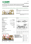
1
Istruzioni per installazione, uso e manutenzione
Montage und Bedienungs Anleitung
Installation, use and maintenance instructions
Manuel d’entretien
I
Bruciatore di nafta
D
Heizölbrenner
GB
F
Heavy oil burner
Brûleur à fioul lourd
Funzionamento bistadio
Zweistufiger Betrieb
Two-stage operation
Fonctionnement à deux allures
CODICE
CODE
MODELLO - MODELL
MODELE - MODEL
TIPO - TYP
TYPE
3433723
3433724
PRESS 30 N
PRESS 30 N
614 M
614 M
2915827 (3) - 01/2009
I
NOTA
In conformità con la Direttiva Rendimento 92/42/CEE, l’applicazione del bruciatore alla caldaia, la regolazione e il collaudo, devono essere eseguiti nell’osservanza del manuale
d’istruzione della caldaia stessa, compreso il controllo della concentrazione di CO e CO2 nei
fumi, della loro temperatura e di quella media dell’acqua della caldaia.
D
BEMERKUNG
In Konformität mit der Wirkungsgradrichtlinie 92/42/EWG müssen die Anbringung des Brenners am Heizkessel, die Einstellung und die Inbetriebnahme unter Beachtung der Betriebsanleitung des Heizkessels ausgeführt werden, einschließlich Kontrolle der Konzentration
von CO und CO2 in den Abgasen, der Abgastemperatur und der mittleren Kesseltemperatur.
GB NOTE
In conformity with Efficiency Directive 92/42/EEC the application of the burner on the boiler,
adjustment and testing must be carried out observing the instruction manual of the boiler, including verification of the CO and CO2 concentration in the flue gases, their temperatures
and the average temperature of the water in the boiler.
F
NOTE
Conformément à la Directive rendement 92/42/CEE, suivre les indications du manuel de la
chaudière pour monter le brûleur, effectuer le réglage et l’essai, contrôler la concentration
de CO et CO2, dans les fumées, leur température et celle moyenne de l’eau de la chaudière.
INDICE
1.
1.1
DESCRIZIONE DEL BRUCIATORE. . . . . . 1
Materiale a corredo . . . . . . . . . . . . . . . . . . 1
2.
2.1
2.2
2.3
DATI TECNICI . .
Dati tecnici . . . . .
Dimensioni . . . . .
Campo di lavoro .
3.
3.1
3.2
INSTALLAZIONE. . . . . . . . . . . . . . . . . . . . 3
Impianti alimentazione olio combustibile . . . . 3
Collegamenti elettrici . . . . . . . . . . . . . . . . . 4
1.
.
.
.
.
.
.
.
.
.
.
.
.
.
.
.
.
.
.
.
.
.
.
.
.
.
.
.
.
.
.
.
.
..
..
..
..
...
...
...
...
....
....
....
....
4.
4.1
4.2
4.3
4.4
4.5
4.6
4.7
4.8
...2
...2
...2
...2
FUNZIONAMENTO . . . . . . . . . . . . . . . . . .
Scelta degli ugelli . . . . . . . . . . . . . . . . . . .
Pressione della pompa . . . . . . . . . . . . . . .
Regolazione testa di combustione . . . . . . . .
Regolazione motorino serranda aria . . . . . . .
Regolazione temperatura di polverizzazione .
Programma di avviamento . . . . . . . . . . . . . .
Diagnostica programma di avviamento . . . . .
Diagnostica mal funzionamento . . . . . . . . . .
5
5
5
5
6
6
7
8
8
DESCRIZIONE DEL BRUCIATORE
Bruciatore di nafta con funzionamento bistadio.
O Il bruciatore risponde al grado di protezione IP 40 secondo EN 60529.
O Bruciatore con marcatura CE in conformità alle Direttive CEE: CEM 89/336/CEE, Bassa Tensione
73/23/CEE, Macchine 98/37/CEE e Rendimento 92/42/CEE.
Fig. 1
D2625
1
2
3
4
5
6
7
10
11
12
13
14
15
16
17
18
-
Raccordo di aspirazione
Raccordo di ritorno
Regolatore pressione pompa
Attacco manometro (G1/8)
Attacco vacuometro (G3/8)
Motorino apriserranda
Pulsante di sblocco apparecchiatura con
segnalazione di blocco
8 - Condensatore
9 - Vite regolazione testa di combustione
1.1
-
Filtro con guaina per termometro
Gruppo valvole
Manometro con rubinetto di protezione
Termostato di regolazione
Contattore preriscaldatore
Trasformatore
Morsettiera
Bocchettoni pressacavo
Valvola antigas
MATERIALE A CORREDO
Tubi flessibili . . . . . . . . . . . . . . . . . . . . . . . . . . . . .
Guarnizioni . . . . . . . . . . . . . . . . . . . . . . . . . . . . . .
Schermo per flangia . . . . . . . . . . . . . . . . . . . . . . .
Prolunghe per guide (per versione testa allungata)
. . N° 2
. . N° 2
. . N° 1
. . N° 2
Nipples . . . . . . . . . . . . . . . . . . . . . . . . . N° 2
Viti . . . . . . . . . . . . . . . . . . . . . . . . . . . . N° 4
Ugelli . . . . . . . . . . . . . . . . . . . . . . . . . . N° 2
5827
1
I
2.
DATI TECNICI
2.1
DATI TECNICI
TIPO
614 M
Potenza termica - Portata
85/171 ÷ 342 kW
Combustibile
Olio viscosità max. a 50° C 50 mm2/s (7° E)
con kit fino a
150 mm2/s (20° E)
Alimentazione elettrica
Monofase, 230 V ± 10%
Motore
3,2 A
Trasformatore d’accensione
Primario 2 A
Riscaldatori
2,8 kW
Potenza elettrica assorbita
3,5 kW
Pompa
65 kg/h a 20 bar
2.2
-
–
7,5/15 ÷ 30 kg/h
~ 50Hz
Condensatore 12,5 µF / 450V
–
Secondario 2 x 6,5 kV – 35 mA
DIMENSIONI
Piastra caldaia
Bruciatore
D2626
D2628
versione testa allungata.
* Per
Per l’arretramento del bruciatore servirsi delle prolunghe ai perni fornite a corredo.
2.3
CAMPO DI LAVORO (2 ugelli funzionanti)
Pressione in camera di
combustione – mbar
D2627
kg/h
kW
Potenzialità bruciatore
Quando il bruciatore funziona con un solo ugello, le condizioni di pressurizzazione sono più favorevoli e
non pongono problemi. Portata minima con un solo ugello: 7,5 kg/h - 85 kW
5827
2
I
3.
INSTALLAZIONE
3.1
IMPIANTI ALIMENTAZIONE OLIO COMBUSTIBILE
IMPIANTO PER GRAVITÀ
Per olio leggero con viscosità max. 7°E / 50°C.
Innesco pompa:
allentare il tappo dall’attacco vacuometro
(5, fig. 1) ed attendere la fuoriuscita del
combustibile.
H: Dislivello
L: Lunghezza del tubo di aspirazione
H
metri
0
0,5
1
1,5
2
L metri
ø 3/4”
ø 1”
5
10
8
15
11
20
14
25
17
30
D2629
IMPIANTO IN ASPIRAZIONE
Per olio leggero con viscosità max. 7°E / 50°C.
D2630
Sconsigliato, a meno che non ci si trovi
in presenza si un impianto già preesistente.
Non si deve superare la depressione max.
di 0,5 bar (38 cm Hg) misurata all’attacco
vacuometro (5, fig. 1).
Si raccomanda che le tubazioni siano a
perfetta tenuta. Quando la cisterna è ad un
livello inferiore del bruciatore, si consiglia
di far arrivare la tubazione alla stessa altezza della tubazione di aspirazione.
In questo caso non è necessaria la valvola
di fondo.
H
metri
0
0,5
1
1,5
2
2,5
3
L metri
ø 1”
ø 1 1/4”
24
45
21
40
18
35
15
30
12
25
9
20
6
15
IMPIANTO AD ANELLO
Per olio denso con viscosità fino a 20°E / 50°C.
D2631
1 - Cisterna (riscaldata per olio denso)
2 - Filtro (con resistenza per olio > 7°E / 50°C)
3 - Bruciatore (con kit per olio denso)
4 - Saracinesche per esclusione bruciatore (accoppiate)
5 - Pompa di trasferimento
6 - Manometro di controllo
7 - Pompa bruciatore
8 - Regolatore di pressione
Nota importante: per agevolare il flusso di combustibile tutte le tubazioni devono essere opportunamente dimensionate, coibentate e riscaldate. (elettricamente o tramite vapore o acqua calda).
Attenzione: accertarsi prima di mettere in funzionamento il bruciatore che il tubo di ritorno non abbia occlusioni.
Un eventuale impedimento provocherebbe la rottura dell’organo di tenuta della pompa.
5827
3
I
3.2
COLLEGAMENTI ELETTRICI
IMPIANTO ELETTRICO DEL BRUCIATORE (eseguito in fabbrica)
RMO88.53A2
TB
16 11
B
4
15 12
5
1
18 9
13 8
17
3 10
FR
C
SM
TE
7
8
6
11
TA
M
MV2 HS1 ST0
Marrone
Nero
Blu
Tm
MV
TM
ST1
S
2
TB
5
5
A2
3
K1
10
A1
1
9
4
1
A1
V1
M +
6
6
-
2 4
2
R1
CR
F
ST2
A2
R2
1 3 5
V2
D2571
R
1
C
CR
F
FR
H
IN
K1
MB
MV
PS
R
RMO
S
SM
TA
TB
TE
TL
TR
TS
Tm
TM
V1
V2
2
3 4
5
Condensatore
Contattore preriscaldatore
Soppressore
Fotoresistenza
Segnalazione di blocco a distanza
Interruttore manuale
Relè
Morsettiera bruciatore
Motore ventilatore
Pulsante di sblocco
Resistenza portaspruzzo
Apparecchiatura elettrica
Preriscaldatore
Servomotore
Trasformatore d’accensione
Terra bruciatore
Termostato di regolazione nafta
Telecomando di limite
Telecomando di regolazione
Telecomando di sicurezza
Termostato min. nafta
Termostato max. nafta
Valvola 1° stadio
Valvola 2° stadio
6
7 8 9
10
11 12
MB
COLLEGAMENTI ELETTRICI ALLA MORSETTIERA
(a cura dell’installatore)
D2572
COLLEGAMENTI RESISTENZE
PRERISCALDATORE
NOTA
Sezione dei conduttori: min. 1 mm2.
(Salvo diverse indicazioni di norme e leggi locali).
FUNZIONAMENTO BISTADIO
Si ottiene mediante il telecomando collegato ai morsetti 7 - 8
(togliendo il ponte) che comanda la seconda valvola.
5827
4
I
D2634
FISSAGGIO CAVI ELETTRICI
Fig. 2
Tutti i cavi elettrici da collegare alla morsettiera (16, fig. 1) vanno
fatti passare per gli opportuni bocchettoni a pressacavo (17, fig. 1),
vedi figura 2.
1 - Alimentazione monofase: . . . . . . . . . . . .
2 - Termostato regolazione: . . . . . . . . . . . . .
3 - Termostato sicurezza: . . . . . . . . . . . . . .
4 - Termostato 2° stadio: . . . . . . . . . . . . . . .
5 - Foro pretranciato
bocchettone Pg 16
bocchettone Pg 13,5
bocchettone Pg 13,5
bocchettone Pg 13,5
D2635
Eventuali altre segnalazioni o comandi possono essere collegati alla morsettiera del bruciatore asportando
la pastiglia metallica dal foro pretranciato e inserendo un comune bocchettone a pressacavo per il passaggio
e fissaggio dei cavi. Per garantire il grado di protezione IP 40 secondo EN 60529 chiudere i fori di passaggio
dei cavi di eventuali bocchettoni inutilizzati con opportune pastiglie.
NOTE
- Eseguire un buon collegamento di terra.
- Verificare l’arresto del bruciatore aprendo il termostato di caldaia e il blocco oscurando la fotoresistenza.
4.
FUNZIONAMENTO
4.1
SCELTA DEGLI UGELLI
4.2
Ugello
GPH (45° - 60°)
20 bar
kg/h
25 bar
kg/h
1,25 + 1,25
15,00
17,00
1,50 + 1,50
18,00
20,30
1,75 + 1,75
21,00
23,80
2,00 + 2,00
24,00
27,10
2,25 + 2,25
27,00
30,50
2,50 + 2,50
30,00
–
Pressione consigliata:
- Olio fluido: 20 bar
- Olio denso: 25 bar (vedi kit di trasformazione)
Le portate degli ugelli indicate in tabella sono nominali, ricavate per un olio combustibile leggero
(viscosità 3 ÷ 5 °E a 50 °C riscaldato a 100 °C).
La portata reale può variare rispetto a quella nominale del ± 5%. Se si desiderano valori intermedi di
portata rispetto a quelli indicati nella tabella è possibile variare la pressione in pompa o comporre diversamente gli ugelli.
La pompa lascia la fabbrica tarata a 20 bar.
In particolare per olio combustibile denso
utilizzare ugelli ad alta resistenza all’usura
(es. Monarch F 80 H0).
4.3
PRESSIONE DELLA POMPA
REGOLAZIONE TESTA DI COMBUSTIONE
kg/h
Si effettua ruotando la vite A, fig. 3 fino a
che la tacca, rilevata dal diagramma, collima con il piano del manicotto B, fig. 3.
D2636
Fig. 3
B
Tacca 4
D2637
A
n° tacche
5827
5
I
4.4
REGOLAZIONE MOTORINO SERRANDA ARIA
SOSTA - Leva azzurra
La leva azzurra è posizionata in fabbrica verticalmente e corrisponde alla condizione di serranda aria totalmente chiusa.
Per avere un’apertura parziale della serranda, spostare tale
leva verso sinistra (segno + sulla targhetta).
La nuova posizione della serranda potrà essere verificata con
l’arresto del bruciatore. Non superare, in ogni caso, la posizione
della leva arancio di 1° stadio.
PRIMO STADIO - Leva arancio
La leva arancio regola la posizione della serranda di prima fiamma, ed è tarabile sia in apertura che in chiusura.
Leva nera
Leva rossa
Leva arancio
Leva azzurra
SECONDO STADIO - Leva rossa e nera
La leva rossa regola la posizione della serranda di seconda
fiamma, ed è tarabile sia in apertura che in chiusura.
La leva nera comanda l’apertura della seconda valvola olio e
deve sempre anticipare di poco la leva rossa, ma mai la leva
arancio di 1° stadio.
4.5
Apertura +
– Chiusura
D2638
REGOLAZIONE TEMPERATURA DI POLVERIZZAZIONE
Termostati di regolazione - di minima - di massima
Il termostato di regolazione impedisce l’avviamento del bruciatore se la temperatura del combustibile non ha
raggiunto il valore necessario per una buona polverizzazione come indicato nel diagramma seguente.
mm2/s °E
Viscosità a 50° C
Guaina per termometro
Manopola di regolazione
termostato
Preriscaldatore
°C
D2640
Scarico impurità
D2641
Temperatura di polverizzazione
Esempio
Un olio combustibile 7 °E a 50 °C va preriscaldato a 110 °C.
Il termostato deve essere generalmente tarato ad un valore di temperatura superiore di quello desiderato
(120° letti sulla manopola per avere circa 100 °C agli ugelli).
La lettura va fatta dopo qualche minuto di funzionamento, poi effettuare i necessari ritocchi.
Il termostato a contatto di minima interviene arrestando il bruciatore nel caso che la temperatura del combustibile scenda sotto il valore necessario per aver una buona combustione.
Il termostato a contatto di massima disinserisce le resistenze quando, a causa di un’avaria del termostato
di regolazione, si registra un sensibile aumento della temperatura nel preriscaldatore. In caso di interventi
anomali accertarsi del regolare funzionamento del termostato di regolazione e della resistenza a contatto
della sonda del termostato stesso.
5827
6
I
NOTE IMPORTANTI
Nel caso si dovesse sostituire il termostato del preriscaldatore o la resistenza a contatto della sonda, questa deve essere posizionata, dopo aver allentato le viti
di fissaggio del pacco tavolette, a contatto della resistenza e delle tubazioni dell’ultima tavoletta come in figura a lato.
Nel caso che durante il funzionamento si registrassero
elevati scarti o punte eccessive di temperatura, verificare con un ohmetro la continuità della resistenza posta a contatto della sonda di temperatura (valore circa
35 Ohm).
Utilizzare soltanto filtri con una scanalatura sull’esagono di avvitamento.
Tubazioni tavoletta
Tavoletta
Resistenza
D2751
Sonda del termostato
NOTE
y Il preriscaldatore può essere dotato di un secondo termostato a contatto di massima.
Questo termostato può essere impiegato per agire da interruttore su un contattore esterno per togliere corrente al preriscaldatore in caso di sovratemperatura (kit cod. 3000800).
y La resistenza R sul portaspruzzo viene collegata alla linea di alimentazione del preriscaldatore (vedi pag. 4).
Quando il bruciatore viene spento, la linea del preriscaldatore deve rimanere alimentata.
Se si disinserisce l’alimentazione del preriscaldatore, bisogna preriscaldare il combustibile per almeno 30 minuti prima di accendere il bruciatore. In caso contrario provvedere ad alimentare la resistenza sul portaspruzzo con una linea monofase indipendente, protetta da un fusibile da 1 A.
Questa linea non dovrà mai essere interrotta quando il bruciatore viene spento.
y Prima dell’avviamento del bruciatore è consigliabile accertarsi che la pompa sia piena di combustibile per non
farla girare a secco per troppo tempo.
y Pulizia dei filtri:
deve essere eseguita periodicamente per non causare inconvenienti al funzionamento del bruciatore.
y Filtro di linea:
posto in aspirazione, provoca l’aumento della depressione in pompa con conseguente rumorosità della stessa. Non superare un valore di depressione, misurato all’attacco vacuometro (5, fig. 1), di 38 cm Hg (5 m.c.a.).
y Filtro preriscaldatore (10, fig. 1):
posto in mandata, provoca una diminuzione della pressione di polverizzazione controllabile al manometro
(12, fig. 1).
RUBINETTO DI PROTEZIONE MANOMETRO
Una volta controllata la pressione di polverizzazione in funzionamento, è conveniente escludere il manometro
(12, fig. 1) dai colpi di pressione che subisce ad ogni avviamento del bruciatore.
Per questo, a bruciatore fermo e manometro a 0 bar, chiudere il rubinetto di protezione.
4.6
PROGRAMMA DI AVVIAMENTO
Normale
Blocco per mancata accensione
Termostato
Motore
Trasf. d’accensione
Valvola 1a fiamma
Valvola 2a fiamma
Spia di blocco
D2713
5827
7
I
4.7
DIAGNOSTICA PROGRAMMA DI AVVIAMENTO
Durante il programma di avviamento, le indicazioni sono esplicate nella seguente tabella:
TABELLA CODICE COLORE
Sequenze
Codice colore
Preventilazione
Fase di accensione
Funzionamento con fiamma ok
Funzionamento con fiamma debole
Alimentazione elettrica inferiore a
~ 170V
Blocco
Luce estranea
Legenda:
4.8
Spento
Giallo
Verde
Rosso
DIAGNOSTICA MAL FUNZIONAMENTO
L’apparecchiatura in dotazione ha una sua funzione diagnostica attraverso la quale è possibile facilmente
individuare le possibili cause di mal funzionamento (segnalazione: LED ROSSO).
Per utilizzare tale funzione, bisogna aspettare almeno dieci secondi dall’istante di messa in sicurezza
dell’apparecchiatura e premere il pulsante di sblocco per un tempo minimo di tre secondi.
Rilasciato il pulsante, il LED ROSSO comincerà a lampeggiare, come illustrato nella seguente figura.
LED ROSSO acceso
aspettare per almeno 10 s
Premere pulsante
per > 3 s
Segnale
Intervallo
3s
Segnale
Gli impulsi del LED costituiscono un segnale intervallato da 3 secondi circa.
Il numero degli impulsi darà le informazioni sui possibili guasti, secondo la seguente tabella:
SEGNALE
CAUSA PROBABILE
2 lampeggi
Non viene rilevato un segnale stabile di fiamma nel tempo di sicurezza:
– guasto alla fotoresistenza;
– guasto alla valvola olio;
– inversione fase/neutro;
– guasto al trasformatore di accensione
– bruciatore non regolato (nafta insufficiente).
3 lampeggi
Il pressostato aria di minima (se installato) non chiude:
– guasto al pressostato aria;
– pressostato aria non regolato;
– intervento del pressostato aria di massima (se installato).
4 lampeggi
Il pressostato aria di minima (se installato) non commuta, oppure luce presente in camera prima dell’accensione:
– guasto al pressostato aria;
– pressostato aria non regolato.
7 lampeggi
Sparizione della fiamma durante il funzionamento:
– bruciatore non regolato (nafta insufficiente);
– guasto alla valvola olio;
– cortocircuito tra la fotoresistenza e la terra.
8 lampeggi
– Guasto termostato di consenso olio;
– Interruzione resistenze riscaldanti.
10 lampeggi
– Errore di collegamento o guasto interno.
5827
8
I
INHALT
1.
1.1
BESCHREIBUNG DES BRENNERS . . . . . 1
Mitgeliefertes Zubehör . . . . . . . . . . . . . . . . 1
2.
2.1
2.2
2.3
TECHNISCHE MERKMALE .
Technische Daten . . . . . . . .
Abmessungen . . . . . . . . . . .
Betriebsbereich . . . . . . . . . .
3.
3.1
3.2
INSTALLATION . . . . . . . . . . . . . . . . . . . . . 3
Brennstoffzuführung . . . . . . . . . . . . . . . . . . 3
Elektrisches Verdrahtungsschema . . . . . . . 4
1.
BESCHREIBUNG DES BRENNERS
.
.
.
.
.
.
.
.
.
.
.
.
.
.
.
.
.
.
.
.
.
.
.
.
.
.
.
.
.
.
.
.
.
.
.
.
.
.
.
.
.
.
.
.
4.
4.1
4.2
4.3
4.4
4.5
4.6
4.7
4.8
2
2
2
2
BETRIEB . . . . . . . . . . . . . . . . . . . . . . . . .
Wahl Der Düsen . . . . . . . . . . . . . . . . . . . .
Pumpendruck . . . . . . . . . . . . . . . . . . . . . .
Einstellung des Brennerkopfes . . . . . . . . . . .
Luftklappenmotor. . . . . . . . . . . . . . . . . . . . . .
Einstellung der Zerstäubungstemperatur . .
Betriebsablauf . . . . . . . . . . . . . . . . . . . . . . .
Diagnostik Betriebsablauf . . . . . . . . . . . . . .
Diagnostik Betriebsstörungen . . . . . . . . . . .
5
5
5
5
6
6
7
8
8
Heizölbrenner mit zweistufigem Betrieb.
O Der Brenner entspricht der Schutzart IP 40 gemäß EN 60529.
O Brenner mit CE-Kennzeichnung gemäß der EWG-Richtlinien: EMV 89/336/EWG, Niederspannungsrichtlinie
73/23/EWG, Maschinenrichtlinie 98/37/EWG und Wirkungsgradrichtlinie 92/42/EWG.
Abb. 1
D2625
1
2
3
4
5
6
7
8
9
-
10
11
12
13
14
15
16
17
18
Vorlaufanschluss
Rücklaufanschluss
Pumpendruckregler
Manometeranschluss (G1/8)
Vakuummeteranschluss (G3/8)
Luftklappenmotor
Entstörtaste des Schaltgerätes mit Störanzeiger
Kondensator
Schraube zur Einstellung des Brennerkopfes
-
Filter mit Schutzmantel für das Thermometer
Ventilgruppe
Manometer mit Schutzabsperrhahn
Einstellbarer Thermostat
Kontaktgeber des Vorwärmers
Transformator
Klemmleiste
Stopfbuchsverschraubungen
Gegengasbildungventil
1.1 MITGELIEFERTES ZUBEHÖR
Schläuche . . . . . . . . . . . . . . . . . . . . . . . . . . . . . . . . . . .
Dichtungen . . . . . . . . . . . . . . . . . . . . . . . . . . . . . . . . . . .
Flanschdichtung . . . . . . . . . . . . . . . . . . . . . . . . . . . . . . .
Gleitverlängerungen (für Ausführung mit verlängertem Kopf)
. 2 St.
. 2 St.
. 1 St.
. 2 St.
5827
1
D
Nippel . . . . . . . . . . . . . . . . . . . . . 2 St.
Schrauben . . . . . . . . . . . . . . . . . . 4 St.
Düsen . . . . . . . . . . . . . . . . . . . . . 2 St.
2.
TECHNISCHE MERKMALE
2.1 TECHNISCHE DATEN
TYP
614 M
Feuerungswärmeleistung - Durchsatz
85/171 ÷ 342 kW
Brennstoff
Öl mit max. Viskosität bis 50° C 50 mm2/s (7° E)
mit Kit bis zu
150 mm2/s (20° E)
Stromversorgung
Einphase,
Motor
Stromaufnahme 3,2A
Zündtransformator
Primär 2 A
Heizpatronen
2,8 kW
Leistungsaufnahme
3,5 kW
Pumpe
65 kg/h bei 20 bar
–
~ 50Hz
–
7,5/15 ÷ 30 kg/h
230 V ± 10%
-
Kondensator 12,5 µF / 450V
Sekundär 2 x 6,5 kV – 35 mA
2.2 ABMESSUNGEN
Kesselplatte
Brenner
D2626
D2628
Ausführung mit verlängertem Kopf.
* Für
Zum Zurückziehen des Brenners die mitgelieferten Stiftverlängerungen benutzen.
2.3 BETRIEBSBEREICH (2 Düsen in Betrieb)
Druck im Feuerraum
mbar
D2627
kg/h
kW
Brennerleistung
Wenn der Brenner mit nur einer Düsen arbeitet, sind die Luftverdichtungsdedingungen günstiger und verursachen
keine Probleme. Mindestdurchsatz mit nür einer Düse: 7,5 kg/h - 85 kW.
5827
2
D
3.
INSTALLATION
3.1 BRENNSTOFFZUFÜHRUNG
FALLSPEISUNG
Für Öl mit einer max. Viskosität von 7°E / 50°C.
Auffüllen der Pumpe:
Den Verschluss des Vakuummeteranschlusses (5, Abb. 1) lösen und das Austreten des Heizöls abwarten.
H: Höhenunterschied
L: Länge der Ansaugschlauches
H
Meter
0
0,5
1
1,5
2
L Meter
ø 3/4”
ø 1”
5
10
8
15
11
20
14
25
17
30
D2629
ANSAUGZULEITUNG
Für Öl mit einer max. Viskosität von 7°E / 50°C.
D2630
Nicht empfehlenswert, ausser es handelt sich um eine schon bestehende
Anlage.
Der am Vakuummeteranschluss
(5, Abb. 1) max. Unterdruck von 0,50 bar
(38 cm Hg) darf nicht überschritten werden.
Wenn der Tank tiefer als der Brenner angebracht ist, empfehlen wir, die Leitungen des Tankes in gleicher Höhe wie die
der Saugleitung enden zu lassen.
In diesem Fall ist ein Fussventil nicht nötig.
H
Meter
0
0,5
1
1,5
2
2,5
3
L Meter
ø 1”
ø 1 1/4”
24
45
21
40
18
35
15
30
12
25
9
20
6
15
RINGLEITUNG
Für Öl mit Viskosität bis zu 20°E / 50°C.
D2631
1
2
3
4
-
Tank (beheizt für dickflüssiges Öl)
Filter (mit Widerstand für Öl > 7°E / 50°C)
Brenner (mit Kit für dickflüssiges Öl)
Gekuppelte Absperrhähne um den Brenner auszuschliessen
5
6
7
8
-
Förderpumpe
Kontrollmanometer
Brennerpumpe
Druckregler
Wichtiger hinweis: um den Fluss des Brennstoffes zu erleichtern, müssen alle Leitungen angemessene
Ausmasse haben, wärmeisoliert und mit Hilfserhitzern versehen sein.
Achtung: vor Anlauf des Brenners überprüfen, dass die Rücklaufleitung nicht verstopft ist.
Eventuelle Behinderungen könnten Beschädigungen an der Wellendichtung der Pumpe hervorrufen.
5827
3
D
3.2 ELEKTRISCHES VERDRAHTUNGSSCHEMA
INNERE BRENNERVERDRAHTUNG (in der Fabrik fertig montiert)
RMO88.53A2
TB
16 11
B
4
15 12
5
1
18 9
13 8
17
3 10
FR
C
SM
TE
7
8
6
11
TA
M
MV2 HS1 ST0
Braun
Schwarz
Blau
Tm
MV
TM
ST1
S
2
TB
5
5
A2
3
K1
10
A1
1
9
4
1
A1
V1
M +
6
6
-
2 4
2
R1
CR
F
ST2
A2
R2
1 3 5
V2
D2571
R
1
C
CR
F
FR
H
IN
K1
MB
MV
PS
R
RMO
S
SM
TA
TB
TE
TL
TR
TS
Tm
TM
V1
V2
2
3 4
5
6
7 8 9
10
11 12
MB
Motorkondesator
Kontaktgeber der Heizwinderstande
ELEKTRISCHE ANSCHLÜSSE AN DER KLEMMELEISTE
Funkentstörer
(vom Installateur auszuführen)
Fotowinderstand
Störabschaltung-Fernmeldung
Schalter für das manuelle Ausschalten des Brenners
Relais
Brenner-Klemmleiste
Gebläsemotor
Entriegelungtaste
Düsenstockwiderstand
Steuergerät
Vorwarmebehälter
Stellmotor
Zündtransformator
Brenner-erdung
D2572
Einstallbarer Thermostat mit Anlaufentblockung
Grenzwert-Fernsteuerung
Einstell-Fernsteuerung
Sicherheits-Fernsteuerung
Kontaktthermostat der min. Temperatur
Kontaktthermostat der max. Temperatur
ANSCHLÜSSE DER WIDERSTÄNDE
1° Stufe Ventil
DES VORWÄRMERS
2° Stufe Ventil
BEMERKUNG
Leiterdurchmesser: min. 1 mm2.
(Außer im Falle anderslautender Angaben durch Normen und örtliche Gesetze).
ZWEISTUFIGER BETRIEB
Man kann durch die zwischen der Klemmen 7 und 8 geschaltete Fernsteuerung (durch Wegnehmen des Bruckes) erhalten, der das 2. Ventil steuert.
5827
4
D
D2634
KABELBEFESTIGUNG
Abb. 2
Alle Kabel, die an die Klemmleiste (16, Abb. 1) angeschlossen werden, müssen gemäss dem untenstehenden Schema durch des
Stopfbuchsverschraubungen (17, fig. 1) geführt werden, see Abb 2.
1 - Einphasesenspeisung: . . .
2 - Regelthermostat: . . . . . . .
3 - Sicherheisthermostat: . . . .
4 - 2. Stufe Thermostat: . . . . .
5 - Vorgestanzte Öffnung
Stopfbuchsverschraubung Pg 16
Stopfbuchsverschraubung Pg 13,5
Stopfbuchsverschraubung Pg 13,5
Stopfbuchsverschraubung Pg 13,5
D2635
Weitere Signalisierungen oder Steuerungen können an die Klemmleiste des Brenners angeschlossen werden,
indem man die Metallscheibche von der vorgestanzten Öffnung entfernt und einen normale Stopfbuchsverschraubung einführt der als Kabeldurchgang dient und für die Befestigung der Kabel sorgt.
BEMERKUNGEN
- Für eine gute Erdung sorgen.
- Durch Öffnen des Kesselthermostaten die Brennerabschaltung überprüfen; durch Verdunkelung des Photowiderstandes die Störabschaltung überprüfen.
4.
BETRIEB
4.1 WAHL DER DÜSEN
4.2 PUMPENDRUCK
GPH (45° - 60°)
20 bar
kg/h
25 bar
kg/h
1,25 + 1,25
15,00
17,00
1,50 + 1,50
18,00
20,30
1,75 + 1,75
21,00
23,80
2,00 + 2,00
24,00
27,10
2,25 + 2,25
27,00
30,50
2,50 + 2,50
30,00
–
Düse
Empfohlener Druck:
- flüssiges Öl: 20 bar
- dickflüssiges Öl: 25 bar (siehe Kit zum Umbau)
Die in der Tabelle angegebenen Durchsätze der Düsen sind nominal und wurden für einen leichten
Brennstoff ermittelt (Viskosität 3 ÷ 5°E / 50°C erhitzt
auf 100°C).
Der wirkliche Durchsatz kann vom nominalen Wert
um ± 5% abweichen. Werden bezüglich der in der
Tabelle angegebenen Durchsätze Zwischenwerte
gewünscht, so kann Pumpendruck geändert oder die
Düsen anderst zusammengestellt werden.
Die Pumpe verlässt die Fabrik auf 20 bar eingestellt.
Ins Besondere für dickflüssiges Öl Düsen mit hoher
Widerstandsfähigkeit gegen Abnutzung verwenden
(z. B. Monarch F 80 H0).
4.3 EINSTELLUNG DES BRENNERKOPFES
Die Einstellung erfolgt indem die Schraube A,
Abb. 3 so gedreht wird, dass die im Diagramm
ermittelte Einstellzahl mit der Ebene der Muffe
B, Abb. 3 übereinstimmt.
D2636
kg/h
Abb. 3
B
Einstellzahl 4
D2637
A
N° Einstellzahl
5827
5
D
4.4 LUFTKLAPPENMOTOR
STILLSTAND - hellblauer Hebel
Der hellblaue Hebel wird in der Fabrik senkrecht eingestellt.
Mit dieser Stellung des Hebels ist die Luftklappe völlig geschlossen. Um eine Teilöffnung der Klappe zu erhalten den
Hebel nach links verstellen (+ Zeichen auf dem Schild).
Die neue Klappenstellung kann bei Brennerstillstand geprüft
werden.
Aus jeden Fall darf die Stellung des orangenen Hebels in der
1. Stufe nicht überschritten werden.
ERSTE STUFE - orangener Hebel
Der orangene Hebel regelt die Stellung der Klappe der zweiten Flamme und kann sowohl in Richtung offen als auch in
Richtung zu eingestellt werden.
Schwarzer Hebel
Roter Hebel
Orangener Hebel
Hellblauer Hebel
Offen +
ZWEITE STUFE - roter und schwarzer Hebel
Der rote Hebel regelt die Stellung der Klappe der zweiten
Flamme und kann sowohl in Richtung offen als auch in Richtung zu eingestellt werden. Der schwarze Hebel regelt die
Öffnung des zweiten Ölventils und muss dem roten Hebel immer leicht voraus sein, darf aber den orangenen Hebel der 1. Stufe nicht überschreiten.
– Zu
D2638
4.5 EINSTELLUNG DER ZERSTÄUBUNGSTEMPERATUR
Einstellbare Temperaturregler - der min. Temp. und max. Temp.
Der einstellbare Temperaturregler verhindert, dass der Brenner anfährt, solange der Brennstoff die zur
optimalen Zerstübung nötige Temperatur noch nicht erreicht hat (s. Tabelle unten).
mm2/s °E
Viscosität bei 50° C
D2640
Schutzmantel für
das Thermometer
Thermostat
einstellknopf
Vorwärmer
°C
Abfluss von
Unreinheiten
D2641
Zerstäubungstemperatur
Beispiel
Brennstoff mit 7°E bei 50°C wir auf ca. 110°C erwärmt.
Der Thermostat muss im allgemeinen auf einen höheren als den gewünschten. Temperaturwert eingestellt
werden (120°, gelesen auf dem Einstellknof um bei den Düsen eine Temperatur von 100° C zu erhalten).
Nach einigen Minuten des Betriebes ablesen und eventuelle Nacheinstellungen durchführen.
Der Kontaktthermostat der min. Temperatur schaltet den Brenner aus, wenn die Brennstofftemperatur
unter den für eine gute Verbrennung nötigen Wert abfällt.
Der Kontaktthermostat der max. Temperatur schaltet den Winderstand aus wenn im Vorwärmer auf
Grund einer Fehlfunktion des Einstellthermostates eine spürbare Temperaturerhöhung festgestellt wird.
Bei anomalen Einstellungen, nachprüfen, dass der Einstellthermostat und der Widerstand in Kontakt mit der
Sonde desselben Thermostates ordnungsgemäss funktionieren.
5827
6
D
WICHTIGE HINWEISE
Müssen der Temperaturregler des Vorwärmers oder der
Widerstand, der mit dem Fühler in Kontakt ist, ausgetauscht werden, so muss dieser Widerstand, nachdem
man die Befestigungsschrauben der Leisteneinheit aufgeschraubt hat, in Kontakt mit dem Widerstand und den
Leitungen der letzten Leiste angebracht werden, (siehe
seitliche Zeichnung).
Falls während des Betriebes zu hohe Temperaturspitzen auftreten, muss mit einem Ohmmeter die Kontinuität
des Widerstandes, der in Kontakt mit dem Temperaturfühler ist, geprüft werden (Wert ca. 35 Ohm).
Nur Filter mit einer Kerbe in der Sechskantverschraubung verwenden.
Leitungen in der Leiste
Leiste
Widerstand
D2751
Fühler des
Temperaturreglers
BEMERKUNGEN
y Der Vorwärmer kann mit einem zweiten Kontaktthermostat der max. Temperatur ausgerüstet sein. Dieser
Thermostat kann als Ausschalter auf einen äusseren Kontaktgeber fungieren, um die Stomzufuhr an den Vorwärmer zu unterbrechen, wenn Übertemperatur vorliegt (Kit Best. Nr. 3000800).
y Der Widerstand R am Düsenstock wird mit der Zuleitung des Vorwärmers verbunden (siehe Seite 4).
Wenn der Brenner ausgeschaltet wird, muss die Zuleitung des Vorwärmers weiter gespeist werden. Wird die
Speisung des Vorwärmers unterbrochen, so muss der Brennstoff für mindestens 30 Minuten erwärmt werden,
bevor man den Brenner einschaltet. Anderenfalls muss der Widerstand am Düsenstock mit einer unabhängigen Monophasenleitung gespeist werden, welche von einer Sicherung 1 A geschützt wird.
Diese Zuleitung darf nie unterbrochen werden, wenn der Brenner ausgeschaltet wird.
y Es ist ratsam, vor Brenneranlauf zu überprüfen, dass die Pumpe mit Brennstoff aufgefüllt ist, damit sie nicht
zu lange Zeit trocken läuft.
y Filterreinigung:
muss regelmässig ausgeführt werden, um Unannehmlichkeiten beim Brennerbetrieb zu vermeiden.
y Filter der Speiseleitung:
in der Ansaugleitung verursacht er erhöhten Unterdruck in der Pumpe und somit geräuschvollen Betrieb dergleichen. Der Unterdruck, gemessen am Vakuummeteranschluss (5, Abb. 1), darf den Wert von 38 cm Hg (5 m
c.a.) nicht überschreiten.
y Vorwärmefilter (10, Abb. 1):
in der Förderlinie verursacht er die Verminderung des Zerstäubungsdruckes, welcher am Manometer (12,
Abb. 1) nachgeprüft werden kann.
SCHUTZABSPERRHAHN DES MANOMETERS
Einst die Zerstäubungsdruck im Betrieb übergeprüft ist, ist es zweckmässig das Manometer (12, Abb. 1) aus den
Druckstossen ausschliessen, die es bei jedem Brenneranlauf trägt.
Daher, bei Stillstand des Brenners und 0 mbar des Manometers, den Schutzabsperrhahn zudrehen.
4.6 BETRIEBSABLAUF
Normal
Störabschaltung wegen Nichtzündung
Thermostat
Motor
Zündtransformator
1. Stufe Ventil
2. Stufe Ventil
Störanzeiger
D2713
5827
7
D
4.7 DIAGNOSTIK BETRIEBSABLAUF
Die Bedeutung der verschiedenen Anzeigen während des Anlaufprogramms ist in folgender Tabelle erklärt:
FARBCODETABELLE
Sequenzen
Farbcode
Vorspülung
Zündung
Betrieb mit Flamme OK
Betrieb mit schwachter Flamme
Stromversorgung unter ~ 170V
Störabschaltung
Fremdlicht
Erläuterung:
aus
gelb
grün
rot
4.8 DIAGNOSTIK BETRIEBSSTÖRUNGEN
Das mitgelieferte Steuergerät hat eine Diagnosefunktion, mit der die möglichen Ursachen von Betriebsstörungen leicht auffindbar sind (Anzeige: ROTE LED).
Um diese Funktion zu benützen, muss man mindestens zehn Sekunden ab dem Augenblick warten, ab dem
das Gerät in Sicherheitszustand ist, dann mindestens drei Sekunden lang auf den Entriegelungsschalter drükken. Nach dem Loslassen des Schalters beginnt die ROTE LED zu blinken, wie in der hier folgenden Abbildung gezeigt.
ROTE LED eingeschaltet
Mindestens 10 s Warten
Mindestens 3 s
auf Entriegelungsschalter
drücken
Signal
3s
Pause
Signal
Die Impulse der LED verursachen ein Signal, das ca. alle 3 Sekunden gegeben wird.
Die Anzahl der Impulse wird Informationen über die möglichen Defekte geben, nach der hier folgenden Tabelle:
SIGNAL
MÖGLICHE URSACHE
2-maliges Blinken
Innerhalb der Sicherheitszeit wird keine stabile Flamme festgestellt:
– Defekt an der Photozelle;
– Defekt an den Ölventilen;
– Umkehrung von Phase/Nullleiter;
– Defekt am Zündtransformator;
– Brenner nicht eingestellt (Schweröl nicht ausreichend).
3-maliges Blinken
Minimalluftdruckwächter (falls installiert) schließt nicht:
– Defekt am Luftdruckwächter;
– Luftdruckwächter schlecht eingestellt;
– Ansprechen des Maximalluftdruckwächters (falls installiert).
4-maliges Blinken
Minimalluftdruckwächter (falls installiert) öffnet nicht oder Licht in der Kammer vor
der Zündung vorhanden:
– Defekt am Luftdruckwächter;
– Luftdruckwächter schlecht eingestellt.
7-maliges Blinken
Erlöschen der Flamme während des Betriebs:
– Brenner nicht eingestellt (Schweröl nicht ausreichend);
– Defekt an den Ölventilen;
– Kurzschluss zwischen Photozelle und Erde.
8-maliges Blinken
– Defekt am Öltemperaturregler;
– Widerstand unterbrochen.
10-maliges Blinken
– Anschlussfehler oder interne Störung.
5827
8
D
INDEX
1.
1.1
BURNER DESCRIPTION . . . . . . . . . . . . . . 1
Burner equipment . . . . . . . . . . . . . . . . . . . 1
2.
2.1
2.2
2.3
TECHNICAL DATA
Technical data . . . .
Overall dimensions
Working field . . . . .
3.
3.1
3.2
INSTALLATION . . . . . . . . . . . . . . . . . . . . . 3
Fuel oil gravity feed systems . . . . . . . . . . . 3
Electrical wiring . . . . . . . . . . . . . . . . . . . . . 4
1.
BURNER DESCRIPTION
.
.
.
.
.
.
.
.
.
.
.
.
.
.
.
.
.
.
.
.
.
.
.
.
.
.
.
.
.
.
.
.
.
.
.
.
.
.
.
.
.
.
.
.
.
.
.
.
.
.
.
.
.
.
.
.
.
.
.
.
.
.
.
.
.
.
.
.
4.
4.1
4.2
4.3
4.4
4.5
4.6
4.7
4.8
.2
.2
.2
.2
WORKING . . . . . . . . . . . . . . . . . . . . . . . .
Choice of nozzles . . . . . . . . . . . . . . . . . . .
Pump pressure . . . . . . . . . . . . . . . . . . . . .
Combustion head setting . . . . . . . . . . . . . . .
Adjustment of the air damper motor . . . . . . .
Spray temperature adjustment . . . . . . . . . . .
Burner start-up cycle . . . . . . . . . . . . . . . . . .
Burner start-up cycle diagnostics . . . . . . . .
Operating fault diagnostics . . . . . . . . . . . . .
5
5
5
5
6
6
7
8
8
Two stage heavy oil burner.
O The burner meets protection level of IP 40, EN 60529.
O Burner with CE marking in conformity with EEC directives: EMC 89/336/EEC, Low Voltage 73/23/EEC,
Machines 98/37/EEC and Efficiency 92/42/EEC.
Fig. 1
D2625
1
2
3
4
5
6
7
8
9
-
1.1
10
11
12
13
14
15
16
17
18
Suction line
Return line
Pump pressure adjustment screw
Manometer plug (G1/8)
Vacuometer plug (G3/8)
Air shutter opening motor
Control box reset push-button and lock-out lamp
Capacitor
Regulating bush for combustion head
-
Sheathed filter for the thermometer
Valves group
Manometer with protection valve
Adjustment thermostat
Pre-heater relay
Ignition transformer
Burner terminal strip
Fair leads
Back-pressure valve
BURNER EQUIPMENT
Flexible tubes . . . . . . . . . . . . . . . . . . . . . .
Seals . . . . . . . . . . . . . . . . . . . . . . . . . . . .
Gasket for flange. . . . . . . . . . . . . . . . . . . .
Extensions for bars (for long - head version)
.
.
.
.
.
.
.
.
.
.
.
.
.No. 2
.No. 2
.No. 1
.No. 2
Nipples. . . . . . . . . . . . . . . . . . . . . . . . . . . No. 2
Screws. . . . . . . . . . . . . . . . . . . . . . . . . . . No. 4
Nozzles . . . . . . . . . . . . . . . . . . . . . . . . . . No. 2
5827
1
GB
2.
TECHNICAL DATA
2.1
TECHNICAL DATA
TYPE
614 M
Thermal power - Output
85/171 - 342 kW
Fuel
Oil with max. viscosity at 50° C 50 mm2/s (7° E)
for oil up to
150 mm2/s (20° E) with kit
Electrical supply
Single phase, 230 V ± 10%
Motor
Run current 3.2 A
Ignition transformer
Primary 2 A
Heaters
2.8 kW
Absorbed electrical power
3.5 kW
Pump
65 kg/h at 20 bar
2.2
–
–
-
7.5/15 - 30 kg/h
~ 50Hz
Capacitor 12.5 µF / 450V
Secondary 2 x 6.5 kV – 35 mA
OVERALL DIMENSIONS
Boiler plate
Burner
D2626
D2628
long - head version.
* For
Apply the extensions provided as accessories for the burner withdrawing.
2.3
WORKING FIELD (2 nozzles in operation)
Pressure in combustion
chamber – mbar
D2627
kg/h
kW
Thermal power
When the burner operates with only one nozzle, the pressurization conditions are improved and no problems arise. Minimal fuel capacity with one only nozzle: 7.5 kg/h - 85 kW.
5827
2
GB
3.
INSTALLATION
3.1
FUEL OIL GRAVITY FEED SYSTEMS
GRAVITY SYSTEM
For fuel oil with viscosity max. 7°E at 50°C.
Priming pump:
loose the tap of the vacuometer plug (5,
fig. 1) and wait for the fuel flow.
H
meters
0
0.5
1
1.5
2
H: Difference in the pipes height
L: Length of the suction pipe
L meters
ø 3/4”
ø 1”
5
10
8
15
11
20
14
25
17
30
D2629
SUCTION SYSTEM
For fuel oil with viscosity max. 7°E at 50°C.
D2630
Not advised, to be used only in
case of previously existing system.
Never overcome the max. depression of 0.5 bar (38 cm Hg).
With higher values the fuel emanates
gas. The pipes shall be perfectly
sealead. When the tank is placed below of the burner level, the return
pipe should reach the same level of
the suction pipe. In this case the foot
valve is not required.
H
meters
0
0.5
1
1.5
2
2.5
3
L meters
ø 1”
ø 1 1/4”
24
45
21
40
18
35
15
30
12
25
9
20
6
15
RING SUPPLY
For heavy oil with viscosity up to 20°E / 50°C.
D2631
1 - Tank (properly heated for heavy oil)
2 - Filter (with resistance for oil > 7°E / 50°C)
3 - Burner (with kit for heavy oil)
4 - Couple of cocks (excluding the burner)
5 - Forwarding pump
6 - Manometer
7 - Burner pump
8 - Pressure adjuster
Notice: all the pipes have to be properly seized, sealed and heated (elec. resistance or hot steam or water) to let
the fuel flow.
Warning: before to put the burner in operation verify that no obstruction exists into the pipes, any obstruction
may damage the sealing of the pump.
5827
3
GB
3.2
ELECTRICAL WIRING
ELECTRICAL WIRING CONNECTIONS (carried out by the factory)
RMO88.53A2
TB
16 11
B
4
15 12
5
1
18 9
13 8
17
3 10
FR
C
SM
TE
7
8
6
11
TA
M
MV2 HS1 ST0
Brown
Black
Blue
Tm
MV
TM
ST1
S
2
TB
5
5
A2
3
K1
10
A1
1
9
4
1
A1
V1
V2
M +
6
6
-
2 4
2
R1
CR
F
ST2
A2
R2
1 3 5
D2571
R
1
C
CR
F
FR
H
IN
K1
MB
MV
PS
R
RMO
S
SM
TA
TB
TE
TL
TR
TS
Tm
TM
V1
V2
2
3 4
5
6
Capacitor
Pre-heater contactor
Suppressor
Photoresistance
Remote lock-out signal
Manual burner stop switch
Relay
Burner terminal strip
Fan motor
Reset push-button
Nozzle holder resistance
Control box
Pre-heater
Servomotor
Ignition transformer
Burner earth
Start-up adjustment thermostat
Limit control device system
High-low mode control device system
Safety control device system
Min. value contact thermostat
Max. value contact thermostat
1st stage valve
2nd stage valve
7 8 9
10
11 12
MB
ELECTRICAL CONNECTIONS TO THE BURNER
TERMINAL STRIP (carried out by the installer)
D2572
PRE-HEATING RESISTANCES
CONNECTIONS
NOTE
Wires of min. 1 mm2 section.
(Unless requested otherwise by local standards and legislation).
TWO STAGE OPERATION
It can be achieved by the control device TR, that controls 2nd stage valve,
connected to terminals 7 and 8 (removing the bridge).
5827
4
GB
D2634
FASTENING OF THE ELECTRICAL WIRES
Fig. 2
All the wires, which have to be connected to the burner terminal
strip (16, fig. 1) shall pass through the fair leads (17, fig. 1), see fig.
2.
1 - Motor mono-phase supply: . . . . . . . . . . . . . . fair lead Pg 16
2 - Control thermostat: . . . . . . . . . . . . . . . . . . . . fair lead Pg 13.5
3 - Safety thermostat:. . . . . . . . . . . . . . . . . . . . . fair lead Pg 13.5
4 - 2nd stage thermostat: . . . . . . . . . . . . . . . . . . fair lead Pg 13.5
5 - Pre-sheared hole
D2635
Further prospective signals or controls can be connected to the burner terminal strip by removing the metal weldnuts from the pre-sheared holes and inserting a commun fair lead for the passage and the clamping of the leads.
NOTES
- Carry out a safe earth connection.
- Verify the burner stop by opening the boiler thermostat and the burner lock-out by darkening the photoresistance.
4.
WORKING
4.1
CHOICE OF NOZZLES
4.2
Nozzle
GPH (45° - 60°)
20 bar
kg/h
25 bar
kg/h
1.25 + 1.25
15.00
17.00
1.50 + 1.50
18.00
20.30
1.75 + 1.75
21.00
23.80
2.00 + 2.00
24.00
27.10
2.25 + 2.25
27.00
30.50
2.50 + 2.50
30.00
–
PUMP PRESSURE
Advised pressure:
- Light oil: 20 bar
- Heavy oil: 25 bar (see modification kit)
Rated deliveries of the nozzles are indicated on the
above list and refer to a light oil having viscosity
from 3 to 5°E at 50° C pre-heated at 100°C.
The effective delivery may vary of ± 5% against the
rated one. In case of requirement of intermediate
values, the pump pressure or the nozzles match
could be changed.
The pump is set by the factory set at 20 bar
In case of very heavy oil it is advised to use
high wear resistance nozzles
(for instance Monarch F 80 H0).
4.3
COMBUSTION HEAD ADJUSTMENT
Turn the screw A, fig. 3 till the set-point,
detected from the diagram, is on the line
with the washer B, fig. 3.
kg/h
D2636
Fig. 3
B
Set-point 4
D2637
A
Set-point
5827
5
GB
4.4
ADJUSTMENT OF THE AIR DAMPER MOTOR
STOP - Blue lever
This lever leaves the factory vertically positioned and corresponds to the complete closing of the air damper. A partial
opening of the air damper might be obtained by moving leftwards this lever (+ on the label).
The new position of the air damper is detectable when the burner is off. Do not overcome the position of the orange lever for the
1st stage.
1st STAGE - Orange lever
The orange lever controls the air damper position for the first
flame, it is adjustable both for opening and closing.
Black lever
Red lever
Orange lever
Blue lever
nd
2 STAGE - Red and black levers
The red lever controls the air damper position for the second
flame, it is adjustable both for closing and opening.
The black lever controls the opening of the second oil valve and
it must always anticipate - for a bit - the red lever, but never the
orange one.
4.5
Opening +
– Closing
D2638
SPRAY TEMPERATURE ADJUSTMENT
Thermostat for adjustment - maximum value - minimum value
Adjustment thermostat prevents the burner start up if the fuel temperature has not reached the required value
for a good spray as indicated in the diagram below.
mm2/s °E
Viscosity at 50° C
Sheath for thermometer
Adjusting knob
of thermostat
Pre-heater
°C
D2640
Purge
D2641
Spray temperature
Example
Fuel oil with viscosity of 7 °E at 50 °C is pre-heated to approximately 110 °C.
The thermostat has to be generally set at a value higher than the required one (120°C indicated on the knob to
get approximately 100°C at the nozzles).
The value read has to be done after some minutes of performance and later the necessary adjustments could be
carried out.
Minimum value contact thermostat intervenes by stopping the burner if the fuel temperature decreases under
the value necessary for a good combustion.
Maximum value contact thermostat switches off the resistances when in case of failure of the adjustment
thermostat, the temperature increases inside the pre-heater. In case of abnormal temperature, make sure of the
regular functioning of control thermostat and of the resistance in contact with the probe of the thermostat.
5827
6
GB
NOTICE
If the pre-heater thermostat or the resistance contacting
the probe should be replaced, the probe has to be positioned in contact with the resistance and with the pipes of
the last aluminium plate, after loosening of the fixing
screws of the aluminium plate, see drawing.
If during the operation exceptional changes or too much
high temperatures should be detected, verify the continuity of the resistance, using and ohmmeter, contacting the
temperature probe (approximately 35 Ohm).
Use only filters marked with a recognizable printing on the
screwing hexagon.
Tubes into aluminium plate
Aluminium
plate
Resistance
D2751
Thermostat probe
NOTE
y The pre-heater might be provided with a second thermostat of maximum value with a manual reset. That ther-
mostat can be used as a switch operating by means of an external commutator, which can take off the current
from the pre-heater in case of over-temperature (Kit code no. 3000800).
y The resistance R placed on the nozzle-holder is wired to the supply line of the pre-heater (see pag. 4).
When the burner is off, the pre-heater supply line shall remain fed. Should the pre-heater line be turned off,
the fuel must be pre-heated for approximately 30 minutes before the burner start-up.
On the contrary, the nozzle-holder resistance shall be supplied with an independent single-phase line, protected by a fuse of 1A.
This line shall never be switched off, when the burner is off.
y Before the burner start-up, verify that the pump is filled of fuel in order to avoid any idling for too long time.
y Filters cleaning:
periodically clean the filters in order to avoid any trouble at the burner operation.
y Supply line filter:
positioned on the suction line, it causes the increase of the depression in the pump with the consequent flow
of gas and noise. Do not overcome the depression of 38 cm Hg (5 m W.c.) (5, fig. 1).
y Pre-heater filter (10, fig. 1):
positioned in the delivery line, it causes a decrease of the spraying pressure which is detectable by use of a
manometer (12, fig. 1).
MANOMETER PROTECTION VALVE
After spray pressure check, it is recommended to cut out the manometer (12, fig. 1) to avoid pressure shock that
it can suffer at every burner starting. Close protection valve when the burner is not working and the manometer
indicate 0 bar.
4.6
BURNER START-UP CYCLE
Normal
Lock-out because no ignition
Thermostat
Motor
Ignition transformer
1st flame valve
2nd flame valve
Lock-out lamp
D2713
5827
7
GB
4.7
BURNER START-UP CYCLE DIAGNOSTICS
During start-up, indication is according to the followin table:
COLOUR CODE TABLE
Sequences
Colour code
Pre-purging
Ignition phase
Operation, flame ok
Operating with weak flame signal
Electrical supply lower than ~ 170V
Lock-out
Extraneous light
Key:
4.8
Off
Yellow
Green
Red
OPERATING FAULT DIAGNOSTICS
The control box has a self-diagnostic system, which easily allows identifying the operating faults (RED LED
signal).
To use this function, wait at least ten seconds from the safety lock out, and then press the reset button for
a minimum of 3 seconds.
After releasing the button, the RED LED starts flashing as shown in the diagram below.
RED LED on
wait at least 10 s
Press button
for > 3 s
Signal
Interval
3s
Signal
The pulses of the LED constitute a signal spaced by approximately 3 seconds.
The number of pulses will provide the information on the possible faults, according to the table below:
SIGNAL
PROBABLE CAUSE
2 flashes
The flame does not stabilise at the end of the safety time:
– faulty photocell;
– faulty or soiled oil valves;
– neutral/phase exchange;
– faulty ignition transformer
– poor burner regulation (insufficient heavy oil).
3 flashes
Min. air pressure switch (if installed) does not close:
– air pressure switch faulty;
– air pressure switch incorrectly regulated;
– max. air pressure switch triggered (if installed).
4 flashes
Min. air pressure switch (if installed) does not open or light in the chamber
before firing:
– air pressure switch faulty;
– air pressure switch incorrectly regulated.
7 flashes
Loss of flame during operations:
– poor burner regulation (insufficient heavy oil);
– faulty or soiled oil valves;
– short circuit between photocell and earth.
8 flashes
– Faulty thermostat for oil permissive signal;
– Heating resistances blown.
10 flashes
– Wiring error or internal fault.
5827
8
GB
SOMMAIRE
1.
1.1
DESCRIPTION DU BRULEUR . . . . . . . . . . 1
Matériel fourni . . . . . . . . . . . . . . . . . . . . . . 1
2.
2.1
2.2
2.3
DONNEES TECHNIQUES
Données techniques . . . .
Dimensions . . . . . . . . . . .
Plage de travail . . . . . . . .
3.
3.1
3.2
INSTALLATION . . . . . . . . . . . . . . . . . . . . . 3
Installation tuyauteris fuel . . . . . . . . . . . . . . 3
Raccordements électriques . . . . . . . . . . . . 4
1.
DESCRIPTION DU BRULEUR
.
.
.
.
.
.
.
.
.
.
.
.
.
.
.
.
.
.
.
.
.
.
.
.
.
.
.
.
.
.
.
.
.
.
.
.
.
.
.
.
.
.
.
.
.
.
.
.
.
.
.
.
4.
4.1
4.2
4.3
4.4
4.5
4.6
4.7
4.8
2
2
2
2
FONCTIONNEMENT. . . . . . . . . . . . . . . . .
Choix des gicleurs . . . . . . . . . . . . . . . . . . .
Pression pompe . . . . . . . . . . . . . . . . . . . .
Réglage tête de combustion . . . . . . . . . . . .
Réglage du moteur du volet d’air . . . . . . . .
Réglage de la temperature de pulverisation .
Cycle de démarrage . . . . . . . . . . . . . . . . . . .
Diagnostic cycle de démarrage . . . . . . . . .
Diagnostic mauvais fonctionnement . . . . .
5
5
5
5
6
6
7
8
8
Brûleur de fioul lourd à fonctionnement à deux allure.
O Brûleur conforme au degré de protection IP 40 selon EN 60529.
O Brûleur avec label CE conformément aux directives CEE: EMC 89/336/CEE, Basse Tension 73/23/
CEE, Machines 98/37/CEE et rendement 92/42/CEE.
Fig. 1
D2625
1
2
3
4
5
6
7
8
9
-
10
11
12
13
14
15
16
17
18
Raccord d’aspiration
Raccord de retour
Régulateur pression pompe
Raccord manomètre (G1/8)
Raccord vacuomètre (G3/8)
Moteur volet d’air
Bouton réarmement et signalisation sécurité
Condensateur
Vis régulation tête de combustion
-
Filtre avec gaine pour thermomètre
Groupe électrovannes
Manomètre avec robinet de protection
Thermostat de régulation
Contacteur préchauffeur
Transformateur
Bornier
Passe-câbles
Vanne antigaz
1.1 MATERIEL FOURNI
Flexibles . . . . . . . . . . . . . . . . . . . . . . . . . . . . . . .
Joints . . . . . . . . . . . . . . . . . . . . . . . . . . . . . . . . .
Joint pour bride . . . . . . . . . . . . . . . . . . . . . . . . . .
Prolonges pour guides (pour version tête longue) .
. . . N° 2
. . . N° 2
. . . N° 1
. . . N° 2
Raccords . . . . . . . . . . . . . . . . . . . . . . . N° 2
Vis . . . . . . . . . . . . . . . . . . . . . . . . . . . . N° 4
Gicleurs . . . . . . . . . . . . . . . . . . . . . . . . N° 2
5827
1
F
2.
DONNEES TECHNIQUES
2.1
DONNEES TECHNIQUES
TYPE
614 M
Puissance thermique - Débit
85/171 ÷ 342 kW
Combustible
Fuel-oil viscosité max. à 50° C
avec Kit, jusqu’à
Alimentation électrique
Monophasée, 230 V ± 10%
Moteur
3,2 A absorbés -
Transformateur d’allumage
Primaire 2 A
Réchauffeurs
2,8 kW
Puissance électrique absorbée
3,5 kW
Pompe
65 kg/h à 20 bar
2.2
–
–
7,5/15 ÷ 30 kg/h
50 mm2/s (7° E)
150 mm2/s (20° E)
~ 50Hz
Condensateur 12,5 µF / 450V
Secondaire 2 x 6,5 kV – 35 mA
DIMENSIONS
Plaque chaudière
Brûleur
D2626
D2628
version tête longue.
* Pour
Pour l’ouverture du brûleur, se servir des prolonges de guides fournies dans ce cas.
2.3
PLAGE DE TRAVAIL (2 gicleurs en fonction)
Pression dans la chambre de
combustion – mbar
D2627
kg/h
kW
Puissance du brûleur
Quand le brûleur fonctionne avec un seul gicleur, les conditions de pressurisation sont plus favorables et ne posent aucun problème. Avec un seul gicleur le débit minimum est: 7,5 kg/h - 85 kW.
5827
2
F
3.
INSTALLATION
3.1
INSTALLATION TUYAUTERIS FUEL
INSTALLATION PAR GRAVITE
Pour huile légère viscosité max. 7°E / 50°C.
Amorçage de la pompe:
desserrer le bouchon du raccord vacuomètre (5, fig. 1) et attendre la sortie du combustible.
H: Denivellation
L: Longueur de la tuyauterie d’aspiration
H
mètres
0
0,5
1
1,5
2
L mètres
ø 3/4”
ø 1”
5
10
8
15
11
20
14
25
17
30
D2629
INSTALLATION EN ASPIRATION
Pour huile légère viscosité max. 7°E / 50°C.
D2630
Déconseillé, sauf si l’on est en présence d’une installation préexistante.
On ne doit pas dépasser la depression
max. de 0,40 bar (30 cm Hg). Au-dessus
de cette valeur, il y a liberation de gaz
dans le combustible.
Les tuyauteries doivent être parfaitement
étanches. Si la citerne est à un niveau inférieur au brûleur, il est conseillé de ramener la tuyauterie retour au même niveau
que celle d’aspiration.
Dans ce cas le clapet de fond n’est pas
d’une absolue necessité.
H
mètres
0
0,5
1
1,5
2
2,5
3
L mètres
ø 1” ø 11/4”
24
45
21
40
18
35
15
30
12
25
9
20
6
15
INSTALLATION EN BOUCLE
Pour huile dense viscosité jusqu’à 20°E / 50°C.
D2631
1 - Citerne (réchauffée pour huile lourd)
2 - Filtre (avec résistance pour huile > 7°E / 50°C)
3 - Brûleur (avec kit pour huile lourd)
4 - Vannes d’isolement du brûleur
5 - Pompe de transfert
6 - Manomètre de contrôle
7 - Pompe brûleur
8 - Régulateur de pression
Notes importante: pour faciliter le flux du combustible, toutes les tuyauteries doivent être correctement
dimensionnées, calorifugées et réchauffées (électriquement, ou à l’aide de vapeur ou d’eau chaude).
Attention: s’assurer, avant de mettre en route du brûleur, que la tuyauterie de retour ne soit pas obstrué.
Si tel était le cas, le dispositif d’étanchéité de la pompe serait endommagé.
5827
3
F
3.2
RACCORDEMENTS ELECTRIQUES
INSTALLATION ELECTRIQUE DU BRULEUR (exécuté en usine)
RMO88.53A2
TB
16 11
B
4
15
12
5
1
18
9
13 8
17
3 10
FR
C
SM
TE
7
8
6
11
TA
M
MV2 HS1 ST0
Marron
Noir
Bleu
Tm
MV
TM
ST1
S
2
TB
5
A2
3
A1
9
4
1
A1
V1
+
10
M
K1
-
6
1
R1
2 4
2
F
ST2
A2
CR
5
R2
1 3 5
6
V2
D2571
R
1
C
CR
F
FR
H
IN
K1
MB
MV
PS
R
RMO
S
SM
TA
TB
TE
TL
TR
TS
Tm
TM
V1
V2
2
3
4
Condesateur du moteur
Contacteur préchauffeur
Suppresseur
Cellule photoresistance
Signalisation de sécurité à distance
Interrupteur manuel
Relais
Bornier brûleur
Moteur ventilateur
Bouton réarmement
Résistance portegicleur
Boîte de contrôle
Reservoir préchauffeur
Servomoteur
Transformateur d’allumage
Terre brûleur
Thermostat de réglage fioul lourd
Télécommande de limite
Télécommande de réglage
Télécommande de sécurité
Thermostat min. fioul lourd
Thermostat max. fioul lourd
Vanne 1ère allure
Vanne 2ème allure
5
6
7
8
9
10
11 12
MB
RACCORDEMENTS ELECTRIQUES AU BORNIER
(réalisés par l’installateur)
D2572
RACCORDEMENTS RESISTANCES
ELECTRIQUES
NOTE
Section conducteurs: min. 1 mm2.
(Sauf des indications différentes prévues par les normes et les lois locales).
FONCTIONNEMENT A DEUX ALLURE
L’on obtient par le télécommande connecté aux bornes 7 et 8 (enlevant le
pont), que commande la seconde vanne.
5827
4
F
D2634
FIXATION CABLES ELECTRIQUES
Fig. 2
Tous les câbles électriques à raccorder au bornier (16, fig. 1) vont
fait passer pour le passe-câble (17, fig. 1), voir fig. 2.
1 - Alimentation monophasée: . . . . . . . . . . . . . . . . goulot Pg 16
2 - Thermostat régulation: . . . . . . . . . . . . . . . . . . . goulot Pg 13,5
3 - Thermostat sûreté: . . . . . . . . . . . . . . . . . . . . . . goulot Pg 13,5
4 - Thermostat 2ème allure: . . . . . . . . . . . . . . . . . . . goulot Pg 13,5
5 - Trou pré-cisaillagé
D2635
Des éventuelles autres signalisations ou commandes peuvent être raccordées au bornier du brûleur en elevant
la plaquette pre-cisaillagée et en entroduisant un passe-câble pour le passage et la fixation des câbles.
NOTE
- Réalisér un bon raccordement de terre.
- Vérifier l’arrêt du brûleur en ouvrant le thermostat de chaudière et la mise en sécurité en obscurcissant la cellule
photorésistance.
4.
FONCTIONNEMENT
4.1
CHOIX DES GICLEURS
4.2
Gicleurs
GPH (45° - 60°)
20 bar
kg/h
25 bar
kg/h
1,25 + 1,25
15,00
17,00
1,50 + 1,50
18,00
20,30
1,75 + 1,75
21,00
23,80
2,00 + 2,00
24,00
27,10
2,25 + 2,25
27,00
30,50
2,50 + 2,50
30,00
–
Pression conseillée:
- Huile fluide: 20 bar
- Huile lourde: 25 bar (voir kit de transformation)
Les débits des gicleurs indiqué sur le tableau sont
nominaux, déterminés pour une huile combustible légère (viscosité 3 ÷ 5° E à 50°C réchauffé à 100°C).
Le débit réel peut varier par rapport au débit nominal
d’environ ±5%. Si l’on désire des valeurs de débits
intermédiaires par rapport à ceux indiqués dans le tableau, on peut faire varier la pression de la pompe ou
composer différemment les gicleurs.
La pompe sort d’usine tarée à 25 bar.
Particulièrement pour huiles combustibles lourdes,
utiliser des gicleurs à haute résistance à l’usure
(ex. Monarch F 80 H0).
4.3
PRESSION POMPE
REGLAGE TETE DE COMBUSTION
S’effectue en tournant la vis A, fig. 3 jusqu’à ce que l’encoche, relevée sur le diagramme, coïncide avec le plan du
manchon B, fig. 3.
D2636
kg/h
Fig. 3
B
Encoche 4
D2637
A
n° encoches
5827
5
F
4.4
REGLAGE DU MOTEUR DU VOLET D’AIR
ARRET - Levier bleu
Le levier bleu, en usine, est positionné verticalement et correspond à la position du volet d’air totalement fermé. Pour avoir
une ouverture partielle du volet d’air déplacer le levier vers la
gauche (signe + sur l’etiquette). La nouvelle position du volet
peut être controlée à l’arrêt du brûleur. Ne pas dépasser, dans
chaque cas, la position du levier orange de 1ère allure.
PREMIERE ALLURE - Levier orange
Le levier orange règle la position du volet en 1ère allure, et est
réglable tant en ouverture qu’en fermeture.
DEUXIEME ALLURE - Levier rouge et noir
Le levier rouge règle la position du volet d’air en seconde allure,
et est réglable tant en ouverture qu’en fermeture. Le levier noire
commande l’ouverture de la seconde électrovanne fuel et doit
toujours précéder de peu le levier rouge, mais jamais le levier
orange de première allure.
4.5
Levier noire
Levier rouge
Levier orange
Levier bleu
Overture +
– Fermeture
D2638
REGLAGE DE LA TEMPERATURE DE PULVERISATION
Thermostat de réglage - de minimum - de maximum
Le thermostat de réglage empêche le démarrage du brûleur si la température du combustible n’a pas atteint la
valeur nécessaire pour une bonne pulvérisation comme indiqué dans le diagramme suivant.
mm2/s °E
Viscosité à 50° C
D2640
Gaine pour thermomètre
Bouton de réglage
du thermostat
Réchauffeur
°C
Purge
D2641
Température de pulvérisation
Exemple
Une huile combustible à 7 °E à 50 °C sera réchauffée à 110 °C environ.
Le thermostat doit être généralement réglé à une température supérieure de celle désirée (120° sur le thermostat pour avoir 100° C aux gicleurs).
La lecture sera faite après quelques minutes de fonctionnement; faire ensuite d’eventuelles retouches si necessaire.
Le thermostat à contact de minima intervient en arrètant le brûleur si la température du combustible descend au-dessous de la valeur nécessaire pour avoir une bonne combustion.
Le thermostat à contact de maxima coupe les resistances lorsque, après un incident du thermostat de
régulation, on constate une augmentation sensible de la température dans le réchauffeur. Dans le cas où il
y avait des interventions anomaux s’assurer du fonctionnement régulier du thermostat de régulation et de
la résistance à contact de la sonde du thermostat même.
5827
6
F
NOTE IMPORTANT
Dans le cas où l’on doit changer le thermostat du réchauffeur ou la résistance à contact de la sonde, celleci doit être positionnée, après avoir desserré les vis de
fixation des plaquettes, au contact de la résistance et
des tuyauteries de la dernière plaquette, comme indiqué dans la figure ci-contre.
Si, pendant le fonctionnement, on énregistre des écarts
élevés ou des pointes excessives de température, verifier avec un ohmètre la continuité de la résistance disposée au contact de la sonde de température (valeur
environ 35 Ohm).
Utiliser seulement des filtres ayant une rainure sur
l’hexagone de vissage.
Tuyauteries plaquette
Plaquette
Résistance
D2751
Sonde du thermostat
NOTE
y Le préchaffeur peut être doté d’un second thermostat à contact de maxima à réarmement manuel.
Ce thermostat peut être utilisé pour agir d’interrupteur sur un contacteur externe afin de couper l’alimentation
électrique du préchauffeur en cas de surchauffe (Kit code 3000800).
y La résistance R sur le portegicleur est branchée à la ligne d’alimentation du réchauffeur (voir page 4).
Quand le brûleur est arrêté, la ligne du réchauffeur doit être alimentée. Si on coupe l’alimentation du réchauffer, alors il faut réchauffeur le fuel pour 30 minutes au moins avant l’allumage du brûleur. Cas contraire, il faut
alimenter la résistance sur le portegicleur par une ligne monophasée indépendante protégée par un fusible
de 1A. Quand on arrête le brûleur, cette ligne ne doit jamais être coupée.
y Avant de mettre en route le brûleur il est conseillé de s’assurer que la pompe est pleine de combustible pour
éviter de la faire tourner à sec trop longtemps.
y Nettoyage des filtres:
doit être réalisé régulièrement afin de en pas nuire au fonctionnement du brûleur.
y Filtre de ligne:
disposé sur l’aspiration, le colmatage de celui-ci provoque l’augmentation de la depression dans la pompe, avec
pour conséquence la libération de gaz. La pompe devient bruyante. Ne pas dépasser une dépression, mesurée
au raccord du vacuomètre (5, fig. 1), de 38 cm Hg (5 m c. e.).
y Filtre du préchauffeur (10, fig. 1):
disposé après la pompe, provoque une diminution de la pression de pulvérisation, contrôlable au manomètre
(12, fig. 1).
ROBINET DE PROTECTION DU MANOMETRE
Une fois vérifiée la pression de pulvérisation en fonctionnement, il est convenable d’isoler le manomètre (12, fig. 1)
de les coups de pression qu’il subit à chaque mise en route du brûleur.
Pour ce motif il faut fermer le robinet de protection lorsque le brûleur est inactif et le manomètre marque 0 bar.
4.6
CYCLE DE DEMARRAGE
Normal
Mise en sécurité par défaut d’allumage
Thermostat
Moteur
Transf. d’allumage
Vanne 1ère allure
Vanne 1ème allure
Signalisation sécurité
D2713
5827
7
F
4.7
DIAGNOSTIC CYCLE DE DÉMARRAGE
Pendant le programme de démarrage, les indications sont expliqées dans le tableau suivant:
TABLEAU CODE COULEUR
Séquences
Code couleur
Préventilation
Phase d’allumage
Fonctionnement avec flamme ok
Fonctionnement avec signal de flamme faible
Alimentation électrique inférieure à ~ 170V
Sécurité
Lumière étrangère
Légende:
4.8
eteint
jaune
vert
rouge
DIAGNOSTIC MAUVAIS FONCTIONNEMENT
La boîte de contrôle fournie de série a une fonction diagnostic qui permet de localiser facilement les causes possibles de mauvais fonctionnement (signalisation: LED ROUGE).
Pour utiliser cette fonction, il faut attendre au moins dix secondes après la mise en sécurité de la boîte de
contrôle et appuyer sur le bouton de déblocage pendant au moins trois secondes.
Le LED ROUGE se met à clignoter après avoir relâché le bouton, comme indiqué sur la figure suivante.
LED ROUGE allumé
attendre au moins 10 s
Appuyer sur le bouton
pendant > 3s
Signal
Intervalle
3s
Signal
Les impulsions du led constituent un signal espacé d'environ 3 secondes.
Le nombre d'impulsions donne des informations sur les pannes possibles, selon le tableau suivant:
SIGNAL
CAUSE PROBABLE
2 clignotements
Un signal stable de flamme n’est pas détecté durant le temps de sécurité:
– anomalie de la photorésistance;
– anomalie vannes fioul;
– inversion phase/ neutre;
– anomalie transformateur d'allumage
– brûleur pas réglé (fioul lourd insuffisant).
3 clignotements
Le pressostat air minimum (s’il est prévu) ne se ferme pas:
– anomalie du pressostat air;
– pressostat air pas réglé;
– intervention du pressostat air maximum (s’il est prévu).
4 clignotements
Le pressostat air minimum (s’il est prévu) ne s’ouvre pas ou il y a une ouverture dans la chambre avant l’allumage:
– anomalie du pressostat air;
– pressostat air pas réglé.
7 clignotements
Disparition de la flamme durant le fonctionnement:
– brûleur pas réglé (fioul lourd insuffisant);
– anomalie vannes fioul;
– court-circuit entre la photorésistance et la terre.
8 clignotements
– Anomalie du thermostat d’accord fioul;
– Résistances interrompu.
10 clignotements
– Erreur de connexion ou avarie à l’intérieur.
5827
8
F
RIELLO S.p.A.
I-37045 Legnago (VR)
Tel.: +39.0442.630111
http:// www.rielloburners.com
Con riserva di modifiche - Änderungen vorbehalten! - Subject to modifications - Sous réserve de modifications