1
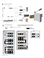
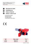
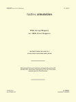
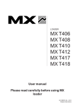
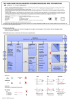
SEM1720 SMART POWERED PROCESS SIGNAL ISOLATOR/CONDITIONER
IMPORTANT - CE & SAFETY REQUIREMENTS
This product is suitable for environment Installation category II pollution degree.
The product is classed as "PERMANENTLY CONNECTED EQUIPMENT".
Product must be DIN rail mounted, inside a suitable enclosure providing environmental protection to IP65 or greater.
Dc supply must be derived from a local supply and not a distribution system.
To maintain CE EMC requirements , input and supply wires must be less than 30 metres.
The product contains no serviceable parts , or internal adjustments. No attempt must be made to repair this product. Faulty units must be returned to supplier for repair.
This product must be installed by a qualified person. All electrical wiring must be carried out in accordance with the appropriate regulations for the place of installation.
Before attempting any electrical connection work, please ensure all supplies are switched off.
The safety of any system incorporating this equipment is the responsibility of the assembler of the system.
ABSOLUTE MAXIMUM CONDITIONS ( To exceed may cause damage to the unit):Supply Voltage
Input Voltage
Input Current
Output
Ambient
External Supply
Isolation
± 240 V dc ± 240 V ac (Protected for over voltage )
± 5 V between any terminals
± 20 mA between terminals
30 V dc
Temperature (-20 to 75) °C Humidity (10 to 95) % RH (Non condensing)
1 Amp anti surge fuse recommended
Between all five ports (C1 Input , Ch2 Input, Ch1 Output, Ch2 Output, Supply) 3.75 KV DC
Every effort has been taken to ensure the accuracy of this document, however we do not accept responsibility for damage, injury, loss or expense resulting from errors and omissions, and we reserve the right of amendment
without notice.
RECEIVE AND UNPACKING
Please inspect the packaging and instrument thoroughly for any signs of transit damage. If the instrument has been damaged, please
notify your supplier immediately.
CLEANING : only clean using damp cloth with water or a mild soap solution.
OPERATION (please refer to data sheet for full technical specification.)
CONFIGURATION
This product is configured using the USB port of a PC running USB_Speed_Link software, available from your supplier. During configuration,
the product is powered directly from the usb port, removing the need for additional power. If the user wishes to monitor live process data
during configuration, then power must be applied.
Note CH1 output and USB port of the device share the same ground, therefore care must be taken to ensure isolation between PC and output
circuit. This is best achieved by using a portable laptop or notebook PC. USB_Speed_Link software is provided with a detailed help menu to
guide the user through the configuration procedure.
For programing / configuration information see help file in USB Speedlink.
D2572-01-01 SEM1720 User Guide
MECHANICAL INSTALLATION
MOUNTING
70°C
Screw driver
Ø 3 mm
-20°C
>= IP65
EN50022 DIN RAIL
ALL DIMS IN mm
ELECTRICAL INSTALLATION
1.0 TURN OFF SUPPLY BEFORE WORKING ON ANY ELECTRICAL CONNECTION.
2.0 SUPPLY IS OVER VOLTAGE PROTECTED AND FUSED WITH INTERNAL FUSE.
3.0 FUSE SUPPLY WITH 1A ANTI SURGE FUSE.
CONNECTION
Use recommended types for cable length (3 to 30)
metres.
Screened Cable
INPUT
Screw Driver
Ø 3 mm
SUPPLY
OUTPUT
Thermocouple
(mV)
+
104
204
205
103
105
Voltage
+
V
out
203
RTD
103
203
102
202
Vdc
S2
206
106
207
107
205
105
-
-
+
mA
207
107
-
101
201
(4 to 20) mA Loop
Slide Wire
104
D2572-01-01 SEM1720 User Guide
207
107
208
108
204
103
203
102
202
101
201
+
S1
+
Vs
-
Vac