1
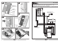
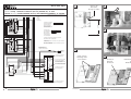
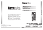
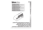
INSTALLATION MANUAL
ADDITIONAL BUTTONS
NOTICE TECHNIQUE
EXTENSION TOUCHES
Bitron Video adotta una politica di continuo sviluppo. Bitron Video
si riserva il diritto di effettuare modifiche e miglioramenti a qualsiasi
prodotto descritto nel presente documento senza preavviso.
Bitron Video follows a policy of continuous evolution of its products.
Therefore Bitron Video reserves the right to introduce changes or
modifications all its products in any moment and without prior
notice.
AV1407/050 • AV1407/051
MANUALE ISTRUZIONI
AGGIUNTIVO TASTI
Bitron Video applique une mèthode de dèveloppement continu.
Par conséquent, Bitron Video se réserve le droit d’apporter des
changements et des améliorations à tout produt décrit dans ce
document, sans aucun préavis.
AV 1407/050 AGGIUNTIVO TASTI - AV 1407/051 AGGIUNTIVO B-fast
ADDITIONAL BUTTONS UNIT AV1407/050 - Bfast ADDITIONAL BUTTONS UNIT AV1407/051
EXTENSION TOUCHES AV1407/050 - EXTENSION TOUCHES Bfast AV1407/051 B-fast
BITRON VIDEO s.r.l.
Via Torino 21/B - 10044 PIANEZZA (Torino) Italy
Tel. +39 011 968.46.11 (r.a.) - Fax +39 011 968.46.18
http://www.bitronvideo.com
e-mail : [email protected]
012175866.00
1
1
2
A175 946 51/D
IMPIANTO VIDEOCITOFONICO “5 FILI” - 1 POSTO ESTERNO VIDEO, 1 UTENTE
“5 WIRES” VIDEO DOORPHONE SYSTEM - WITH 1 VIDEO VISITOR PANEL, 1 USER
SISTEME VIDEO A “5 FILS”, AVEC 1 PLATINE, 1 UTILIZATEURS
Tasti T1÷T6
Pushbutton T1÷T6
Touches T1÷T6
AV 1407/050
All rights reserved - Diritti riservati a Norma di Legge
AV 1423/001 +
AV 1423/010
T1
Led verde
Led green
Del verte
T5
4
H
G/T
G/T2
T3
T4
Rubrica
Directory
Répertoire
L
T2
T6a
T6b
NC
C
NO
3
Led rosso
Led red
Del rouge
LV
LR
+LED
off
J1
segreto
SW1
Deviatore
Switch
Commutateur
Q1
Q1
Q2
Q2
LD
P
T
C
E
B
A
3
1
Suoneria Esterna in CC
Sonnerie additionnelle en CC
External DC Ringer
+
_
Pre-rotture
Pre-cut segments
Pré-découpages
RETE MAINS
AV 7362
230 0
A 70/IRC
3 3
M 1 C _+ D R
Da asportare
Remove
A extraire
1
5
Serratura
Lock
Gache
N N
ANCP
Apriporta esterno
External door opener
Bouton de sortie
Serratura supplementare
Additional lock
Gache additionnelle
6
P1
P2
L
L
CD 1-2
1
3
A
B
V
S
0
CP
CH
CD
9
Ap
+
_
AN 6082/L ( GVM 70/1 )
2
012175866.00
012175866.00
11
A179 233 39/C
1
7
Accesso cavi
Wire access
Passage des câbles
(SISTEMA “4 + n”) - IMPIANTO INTERCOM (AN1349) CON POSTO ESTERNO “N” UTENTI
(“4 + n” SYSTEM) - INTERCOM SYSTEM WITH (AN1349) OUTDOOR SET, “N” USER
(SYSTEME “4 + n”) - SYSTEME INTERCOM (AN1349) AVEC PORTIER ELECTRONIQUE, “N” USAGERS
1
8
All rights reserved - Diritti riservati a Norma di Legge
Level -1
T1
T2
G/T
AK 7034
11
6
Ad altri
citofoni
to other
doorphones
G/T2
T3
Connettore di Chiusura
Senza Collegamenti
T4
T5
T6b
C
NO
LV
LR
+LED
AV 1407/050
C7
P
1
2
9
6
Au
Au
1,5 m
Closure Connector
without connection
T6a
NC
Connecteur Fermeture
sans connections
Connettore Bus
Con Collegamenti
AV 1407/001
9
BUS Connector
with connection
Connecteur BUS
avec connections
Level 0
T1
T2
G/T
AK 7034
11
6
G/T2
In questa configurazione eliminare la funzione
del ponticello "RC" nel GAM3000
In this configuration remove the "RC" jumper function
on GAM3000
T3
T4
T5
T6a
T6b
NC
C
NO
LV
LR
+LED
AV 1407/050
C7
P
1
2
9
6
Au
Au
Dans cette configuration enlever la fonction du pontet
"RC" dans le GAM3000
Apriporta esterno
External door opener
Touche ouvre exterieur
serratura
lock
Serrure
AV 1407/001
Connettore di Chiusura
Senza Collegamenti
RC
0
2 2PE
1PE +
_
1
0
RETE
MAINS
RESEAU
6
C1
240 C
220 3B
110 3A
0
CP
AN 1349
1
2
CH
Y
CP
C2
C1
AV 0052/52
GAM 3000
(4+n)
Int
Est
Per le funzioni dei ponticelli
Vedi manuale istruzioni
10
Viti di fissaggio
Fastenings screws
Vis de fixation
For jumpers' function
see the instructions manual
Pour la function des pontets
voir le manuel d'istructions
11
Connettore
Connector
Connecteur
Canalizzazione
Duct
Canalisation
R E
Connettore di Chiusura
Senza Collegamenti
P1
P2
P3
CP
CD
P4
P5
P6
AV 0045/..
PSM 3000/..
0
Connettore di Chiusura
Senza Collegamenti
10
012175866.00
012175866.00
3
ITALIANO
T6a - T6b
N.C.
C
N.O.
LV
AGGIUNTIVO TASTI AV1407/050 (fig. 1)
L’aggiuntivo tasti può essere utilizzato in abbinamento con i citofoni e con i monitor dotati di staffa della
linea T-LINE.
LR
+LED
L’aggiuntivo rende disponibile:
• 6 pulsanti (T1÷T6) per chiamate intercomunicanti o attivazione di qualsiasi comando (luci scale ecc.): i
pulsanti possono essere utilizzati, fino ad un massimo di tre gruppi di alimentazioni separate;
• 1 deviatore “•°” rende disponibile un contatto libero in scambio;
• un led verde di segnalazione vincolato alla posizione del deviatore “•°”: solo con il deviatore in posizione
premuta, il led sarà in grado di accendersi. L’utilizzo più frequente del pulsante “•°” e del led verde
di segnalazione è comandare automaticamente l’apertura dell’elettroserratura a seguito di una chiamata
citofonica con l’ausilio di un relè di attuazione universale AN0614 (RU60). L’accensione del LED segnala
l’attivazione della funzione;
• un led rosso disponibile per segnalare qualsiasi informazione, ad esempio lo stato di apertura della porta.
Tutti i contatti disponibili, non possono essere utilizzati per attuare carichi alimentati a tensioni
superiori a 24V o con consumi maggiori di 200mA.
AGGIUNTIVO TASTI B-Fast AV1407/051
Contact normalement ouvert;
Extrémité du contact normalement fermée du commutateur “__”;
Commun du commutateur “__”;
Extrémité du contact normalement ouverte du commutateur “__”;
Retour pour activer la signalisation lumineuse de la diode verte. L’activation de la signalisation
dépend directement de la position du commutateur “__”: le voyant pourra s’allumer uniquement
si le commutateur est en position enfoncée. L’utilisation la plus fréquente de la touche “__” et
du voyant vert de signalisation consiste à commander automatiquement l’ouverture de la serrure
électrique en cas d’appel interphone. L’illumination de la DEL signale cet automatisme;
Retour pour activer la signalisation lumineuse rouge : une utilisation possible est la signalisation
de l’état de porte ouverte;
Positif d’alimentation commune aux deux signalisations lumineuses.
CONTENU DE LA BOITE
La boîte contient :
• Extension touches
• Manuel d’instructions
• Confection de deux chevilles et des vis relatives
• Deux vis autotaraudeuses par déformation 3x10 mm
• Câble plat pour connexion à étrier Bi-Fast (uniquement pour AV1407/051)
CARACTERISTIQUES TECHNIQUES
♦ Tension d’alimentation des voyants del:........................................................................... 12 ± 5% Vdc
♦ Courant maximum absorbé par +LED avec alimentation +12Vdc:....................................................50 mA
♦ Tension maximale contacts touches/commutateur: .....................................................................30 Vcc
♦ Courant maximum contacts touches/commutateur: .................................................................... 200mA
♦ Température de service:................................................................................................ -5°C ÷ +50°C
♦ Température de stockage: ............................................................................................-10°C ÷ +60°C
L’aggiuntivo AV1407/051 incrementa le funzioni di un qualsiasi posto interno installato nell’impianto:
• 5 pulsanti (T1÷T5) sono disponibili per essere programmati come chiamate intercomunicanti o come
comandi per attuatori remoti;
• un pulsante (T6) è disponibile sulla morsettiera per pilotare un carico con l’ausilio di un relè di attuazione
universale AN0614 (RU60);
• un deviatore “•°” permette di realizzare la funzione di apertura automatica della porta a seguito di
chiamata;
• un led verde segnala l’attivazione della funzione di apriporta automatico attivato dal deviatore “•°”;
• un led rosso permette di visualizzare lo stato “porta aperta” nel caso sia stato cablato sul posto esterno
“Principale” un sensore porta sui morsetti “SAP / 0”.
Sur interphones série T-Line
PROGRAMMAZIONE TASTI
3)
La procedura di programmazione dei tasti T1÷T5 è la medesima descritta nel libretto istruzioni della
staffa B=FAST AV1423/011 per quanto riguarda le chiamate intercomunicanti e sul libretto della decodifica
AV4005/018 per quanto riguarda le attivazioni di comandi remoti.
La cancellazione delle programmazioni è simultanea alla cancellazione delle programmazioni eseguite sui tasti
presenti sul monitor (vedi libretto istruzioni della staffa B=FAST AV1423/011);
4)
Morsetti:
1)
2)
1)
2)
3)
5)
6)
012175866.00
fixer au mur l’extension touches à l’aide des chevilles fournies en veillant à faire correspondre la sortie
des câbles avec l’œillet prévu pour le passage des câbles ;
exécuter le câblage de l’extension conformément aux indications des schémas d’installation appropriés
(voir schémas d’installation en annexe)
ouvrir le cache de l’interphone et fixer sa base sur l’extension à l’aide de deux vis autotaraudeuses par
déformation 3x10 fournies de série dans les orifices indiqués à la fig. 2 ;
exécuter le câblage de l’interphone.
Sur les étriers pour vidéophones série T-Line
4)
T1, T2
contatti normalmente aperti rispetto al loro morsetto comune G/T;
G/T
comune dei pulsanti T1 e T2
G/T2
comune dei pulsanti T3, T4 e T5
T3, T4 e T5 contatti normalmente aperti rispetto al loro morsetto comune G/T2;
T6a - T6b contatto normalmente aperto;
C
comune del deviatore T7;
4
INSTALLATION
séparer le fond de l’extension au niveau des lignes de pré-découpage prévues (fig. 3);
Extraire les deux éléments indiqués sur l’étrier du moniteur (fig. 4 - 5):
fixer l’étrier au mur à l’aide des chevilles fournies en veillant à faire correspondre la sortie des câbles avec
l’œillet prévu pour le passage des câbles (fig. 6 - 7);
monter l’extension au-dessus de l’étrier conformément au dessin et le fixer au moyen des vis
autotaraudeuses par déformation 2,2x8 fournies de série (fig. 8 - 9 - 10);
uniquement pour l’extension AV1407/051 à utiliser dans les installations B=FAST: raccorder le câble plat
fourni en le faisant passer sous la canalisation (fig. 11);
câbler l’étrier selon les indications du schéma relatif.
012175866.00
9
N.C.
N.O.
LV
FRANÇAIS
capo del contatto normalmente chiuso del deviatore T7;
capo del contatto normalmente aperto del deviatore T7;
ritorno per attivare la segnalazione luminosa verde il led verde. L’attivazione della segnalazione è
direttamente collegata alla posizione del deviatore T7: solo con il deviatore in posizione premuta,
il led sarà in grado di accendersi. L’utilizzo più frequente del pulsante T7 e del led verde
di segnalazione è comandare automaticamente l’apertura dell’elettroserratura a seguito di una
chiamata citofonica. L’accensione del LED segnala tale automatismo;
ritorno per attivare la segnalazione luminosa rossa: un possibile utilizzo è la segnalazione dello
stato di porta aperta;
positivo di alimentazione comune alle due segnalazioni luminose.
EXTENSION TOUCHES AV1407/050 (fig. 1)
LR
L’extension touches peut être utilisée avec les interphones et les moniteurs de la ligne T-LINE.
+LED
Cette extension permet de disposer de:
• 6 touches (T1÷T6) pour les appels intercom ou pour l’activation d’une commande quelconque (éclairage
palier etc.): les touches peuvent être utilisées, avec trois unités d’alimentation séparées. Chaque unité
dispose de son propre commun.
• Un commutateur “•°” permet de disposer d’un contact libre en échange;
• Un voyant vert de signalisation lié à la position du commutateur “•°”: le voyant pourra s’allumer
uniquement si le commutateur est en position enfoncée. La touche “•°” et le voyant vert de signalisation
sont habituellement utilisés pour commander automatiquement l’ouverture de la serrure électrique en cas
d’appel interphone opéré au moyen d’un relais d’activation universel AN0614 (RU60). L’illumination du
voyant signale l’activation de la fonction;
• Un voyant rouge pour signaler une information quelconque, par exemple l’état d’ouverture de la porte.
CONTENUTO DELLA CONFEZIONE
Tous les contacts disponibles ne peuvent être utilisés pour activer des charges présentant une
alimentation supérieure à 24 V ou des consommations supérieures à 200 mA.
EXTENSION TOUCHES Bfast AV1407/051
L’extension AV1407/051 permet d’accroître les fonctions d’un poste interne quelconque situé dans
l’installation:
• 5 touches (1 ÷ 5) sont disponibles et peuvent être programmées en tant qu’appels intercom ou commandes
d’actionneurs distants;
• une touche “6” est disponible sur le bornier pour piloter une charge par le biais d’un relais d’activation
universel AN0614 (RU60);
• une touche de commutation “•°” permet de réaliser la fonction d’ouverture automatique de la porte en cas
d’appel;
• un voyant vert signale l’activation de la fonction ouvre-porte automatique au moyen de la touche de
commutation “•°”;
• un voyant rouge permet de visualiser l’état de “porte ouverte” en cas de câblage sur la platine extérieure
“Principale” d’un capteur porte sur les bornes “SAP / 0”.
La confezione contiene:
• Aggiuntivo tasti
• Manuale istruzioni
• Confezione di due tasselli completi di viti
• Due viti autoformanti 3x10mm
• Cavo piatto per connessione a staffa Bi-Fast (solo per AV1407/051)
CARATTERISTICHE TECNICHE
♦ Tensione di alimentazione dei led: ................................................................................... 12 ±5% Vdc
♦ Corrente massima assorbita da +LED con alimentazione +12Vdc: ...................................................50 mA
♦ Massima tensione contatti pulsanti/deviatore:.......................................................................... 30 Vdc
♦ Massima corrente contatti pulsanti/deviatore: .......................................................................... 200mA
♦ Temperatura di funzionamento: ..................................................................................... -5°C ÷ +50°C
♦ Temperatura di immagazzinamento: ............................................................................. -10°C ÷ +60°C
INSTALLAZIONE
Su citofoni serie T-Line
1)
2)
3)
4)
installare a muro con i tasselli in dotazione, facendo coincidere l’uscita cavi in corrispondenza dell’asola
prevista per l’ingresso cavi;
eseguire il cablaggio dell’aggiuntivo come indicato negli schemi di installazione opportuni (vedi schemi
allegati)
aprire la cappa del citofono e fissarne la base sull’aggiuntivo con le due viti autoformanti 3x10 fornite a
corredo nei fori indicati (fig. 2);
eseguire il cablaggio del citofono.
PROGRAMMATION TOUCHES
Su staffe per monitor T-Line
La procédure de programmation des touches 1÷5 correspond à celle décrite dans la notice d’instructions
de l’étrier Bfast AV1423/011 concernant les appels intercom et dans la notice du décodeur AV4005/018
concernant les activations de commandes distantes.
Les programmations sont éliminées simultanément à la suppression des programmations exécutées sur les
touches présentes sur le moniteur (voir notice d’instructions de l’étrier Bfast AV1423/011);
1)
2)
3)
Bornes:
5)
T1, T2
G/T
G/T2
T3, T4 et T5
8
4)
6)
Contacts normalement ouverts par rapport à leur borne commune G/T;
Commun des touches T1 et T2
Commun des touches T3, T4 et T5
Contacts normalement ouverts par rapport à leur borne commune G/T2;
012175866.00
separare il fondo dell’aggiuntivo in corrispondenza delle previste linee di pre-rottura (fig. 3);
asportare i due particolari indicati sulla staffa del monitor (fig. 4 -5);
fissare la staffa a muro con i tasselli in dotazione, facendo coincidere l’uscita cavi in corrispondenza
dell’asola prevista per l’ingresso cavi a 1,5m da terra (fig. 6 -7);
montare l’aggiuntivo sopra la staffa come a disegno e fissarlo con le viti autoformanti 2,2x8 fornite a
corredo (fig. 8 - 9 - 10);
solo per l’aggiuntivo AV1407/051 da utilizzare in impianti B-Fast: collegare il cavo piatto a corredo
facendolo passare sotto la canalizzazione (fig. 11);
cablare la staffa come indicato nello schema relativo.
012175866.00
5
ENGLISH
LR
+LED
of the “•°” switch: the LED will light up only when the switch is in pressed position. The
“•°” button and green LED are most frequently used to automatically operate the lock after
receiving a doorphone call. The LED will light up to indicate that this automatic function is
active;
Feedback for red LED indicator: this may be used for indicating that the door is open;
Common power positive to the two light sources.
ADDITIONAL BUTTONS UNIT AV1407/050 (fig. 1)
CONTENTS
The additional buttons unit may be used in combination with T-LINE doorphones and monitors.
The box contains:
• Additional buttons unit
• Instruction manual
• Two bolts and screws.
• Two self-tapping screws 3x10mm
• Flat wire for connecting to Bi-Fast bracket (AV1407/051 only)
The additional unit provides:
• 6 buttons (T1-T6) for intercom calls or for operating a variety of controls of any type (staircase lights, etc.):
the buttons may be used with three separate power groups. Each group has its own common.
• A switch “•°” provides a free switching contact;
• The operation of a green LED is linked to the position of switch “•°”: the LED will light up only when
the switch is in pressed position. The most common use of button “•°” and green LED is to automatically
indicate the opening of the lock after receiving a door phone call with the use of a universal actuating relay
AN0614 (RU60). The LED will light up to indicate that the function is on;
• A red LED may be used to indicate any other information, e.g. when a door is open.
The available contacts may only be used to actuate loads powered at no higher than 24V or with
consumption no higher than 200mA.
TECHNICAL SPECIFICATIONS
♦ LED power voltage: ........................................................................................................ 12 ±5% Vdc
♦ Maximum current absorbed by +LED with +12Vdc power: .............................................................50 mA
♦ Maximum voltage button/switch contacts: ............................................................................... 30 Vdc
♦ Maximum current button/switch contacts: ............................................................................... 200mA
♦ Working temperature range: ...........................................................................................-5°C - +50°C
♦ Storage temperature range:.......................................................................................... -10°C - +60°C
B-Fast ADDITIONAL BUTTONS UNIT AV1407/051
INSTALLATION
The additional unit AV1407/051 increases the functions of any apartment station in the system:
• 5 buttons (1-5) are available to be programmed for intercom calls or to control remote actuators;
• button “6” is available on the panel to operate an auxiliary load with an AN0614 (RU60) universal actuating
relay;
• A switching button “•°” may be used to automatically open the door following reception of a call;
• A green LED indicates activation of the automatic door opening function after the switching button is
pressed “•°”;
• A red LED indicates “open door” status: a door sensor must be fitted on the “SAP / 0” terminals of the “Main”
entrance panel for this function.
On T-Line doorphones
BUTTON PROGRAMMING
On T-Line video doorphone brackets
The programming procedure of buttons 1-5 is described in the B-Fast AV1423/011 bracket instruction manual
(intercom calls) and in the AV4005/018 decoder manual (remote control actuation).
Settings are deleted along with the monitor button settings (see B-Fast bracket AV1423/011 instruction
manual);
1)
2)
3)
1)
2)
3)
4)
4)
Terminals:
5)
T1, T2
G/T
G/T2
T3, T4 and T5
T6a - T6b
N.C.
C
N.O.
LV
6
Normally open contacts with respect to common G/T terminal
T1 and T2 button common
T3, T4 and T5 button common
Normally open contacts with respect to common G/T2 terminal
Normally open contact
Contact terminal normally closed by “•°” switch;
“•°” switch common;
Contact terminal normally opened by “•°” switch;
Feedback for activating green LED light button. The signal is directly connected to the position
012175866.00
6)
Install the additional buttons unit on the wall using the bolts provided making the wire outlet corresponds
to the slot for wire entrance.
Connect wires of the additional buttons unit as shown in the attached installation diagrams (see
diagrams).
Open the doorphone hood and fix the base onto the additional buttons unit with the two self-tapping
screws 3x10 supplied in the holes shown in fig. 2.
Connect doorphone wires.
Break the bottom of the additional buttons unit at the pre-cut lines (fig. 3).
Remove the two parts shown on the monitor bracket (fig. 4 - 5).
Install on the wall using the bolts provided making the wire outlet corresponds to the slot for wire
entrance at 1.5 m from the ground (fig. 6 - 7).
Fit the additional buttons unit over the bracket as shown in the drawing and fasten it with the selftapping screws 2.2x8 supplied (fig. 8 - 9 - 10).
For additional buttons unit AV1407/051 used in B=FAST systems: connect the flat wire supplied passing
it underneath the duct (fig. 11).
Connect the bracket as shown in the corresponding diagram.
012175866.00
7


![[ AN 0614 ] I F](http://vs1.manualzilla.com/store/data/006435313_1-38aab84b606e33e62f5bc457d36ab56a-150x150.png)