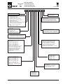
1
All rights reserved © WAMGROUP
BELLOJET®
•
LOADING BELLOWS
•
VERLADEGARNITUREN
•
CHARGEURS TELESCOPIQUES
•
SCARICATORI TELESCOPICI
CATALOGUE No. TO.500EX
ISSUE
CIRCULATION
LATEST UPDATE
A1
100
11.07
All the products described in this catalogue are manufactured according to TOREX® S.p.A. Quality System
procedures.
The Company’s Quality System, certified in July 1994 according to International Standards UNI EN ISO 9001-2000
ensures that the entire production process, starting from the processing of the order to the technical service after
delivery, is carried out in a controlled manner that guarantees the quality standard of the product.
Alle in diesem Katalog beschriebenen Erzeugnisse werden in Konformität mit dem Qualitätssystem der TOREX®
S.p.A. hergestellt.
Das im Juli 1994 zertifizierte Qualitätssystem entspricht der Norm UNI EN ISO 9001-2000 und gewährleistet
dem Kunden eine strenge Qualitätskontrolle in jeder Phase des Produktionprozesses bis hin zum Kundendienst
nach Auslieferung der Ware.
Tous les produits décrits dans ce catalogue ont été réalisé selon les modalités opérationnelles définies Système
de Qualité de TOREX® S.p.A.
Le système de Qualité de l’entreprise, certifié au mois de juillet 1994 en conformité aux Normes Internationales UNI
EN ISO 9001-2000 est en mesure d’assurer que le procédé entier de production, à partir de la formulation de la
commande jusqu’au service technique après la livraison, soit effectué de manière contrôlée et appropriée afin de
garantir le standard de qualité du produit.
Tutti i prodotti descritti in questo catalogo sono stati realizzati secondo modalità operative definite Sistema
Qualità di TOREX ® S.p.A.
Il Sistema Qualità aziendale, certificato dal luglio 1994 in conformità alle Normative Internazionali UNI EN ISO
9001-2000 è in grado di assicurare che l’intero processo produttivo, dalla formulazione dell’ordine fino all’assistenza tecnica successiva alla consegna, venga effettuato in modo controllato ed adeguato a garantire lo
standard qualitativo del prodotto.
UNI EN ISO 9001-2000
Certified Company
This publication cancels and replaces any previous edition and revision.
We reserve the right to implement midifications without notice.
This catalogue cannot be reproduced, even partially, without prior consent.
Diese Veröffentlichung annuliert und ersetzt jeder hergehende Edition oder Revision.
WAM® behält sich das Recht vor, Anderungen ohne vorherige Informationen durchzuführen.
Cette publication annule et remplace toutes les autres précédentes.
Nous nous réservons le droit d’apporter toutes modifications à nos produits.
La reproduction et la publication partielle ou totale de ce catalogue est interdite sans notre autorisation.
Questa pubblicazione annulla e sostituisce ogni precedente edizione o revisione.
Ci riserviamo il diritto di apportare modifiche senza preavviso.
E’ vietata la riproduzione anche parziale senza autorizzazione.
- INDEX
BELLOJET
11.07
- INHALTSVERZEICHNIS
- INDEX
- INDICE
TO.500EX INDEX
DESCRIPTION AND TECHNICAL CHARACTERISTICS........................................................
MODULAR CODE KEY................................................................................................................
MANUFACTURING DATA...........................................................................................................
SCOPE AND IMPORTANCE OF THE MANUAL.......................................................................
WARNING.....................................................................................................................................
INDICATIONS FOR THE USE....................................................................................................
OPERATING CONDITIONS .......................................................................................................
SPECIAL FEATURES...................................................................................................................
DECLARATION OF CONFORMITY............................................................................................
APPLICATION OF DIRECTIVE ATEX..........................................................................................
DECLARATION OF CONFORMITY............................................................................................
INSTALLATION..............................................................................................................................
MAINTENANCE: ADJUSTEMENT OF UP/DOWN LIMIT SWITCH.........................................
RESIDUAL RISKS........................................................................................................................
BESCHREIBUNG UND TECHNISCE MERKMALE...................................... M .01
SUCHCODESCHLÜSSEL.....................................................................................02→.05
KONSTRUKTIONSDATEN....................................................................................06
ZWECK UND BEDEUTUNG DES HANDBUCHS...............................................07
HINWEISE...............................................................................................................08→.11
ANGABEN ZUM GEBRAUCH............................................................................. .12→.14
EINSATZEINSCHRÄNKUNGEN ..........................................................................15
SPEZIELLE EINGENSCHAFTEN........................................................................ .16
KONFORMITÄTSERKLÄRUNG.......................................................................... .17
ANWENDUNGEN DER ATEX-RICHTLINIE........................................................18
KONFORMITÄTSERKLÄRUNG............................................................................19→.22
EINBAU.................................................................................................................. .23→.27
WARTUNGSANLEITUNG: EINSTELLUNG ENDSCHALTER OBEN/UNTEN. .28→.30
RESTRISIKEN...................................................................................................... .31→.32
DESCRIPTION ET CATACTERISTIQUES TECNIQUES.........................................................
CODE SIGLE MODULAIRE..........................................................................................................
DONNÉES COSTRUCTIVES......................................................................................................
BUT ET IMPORTANCE DU MANUEL.........................................................................................
RECOMMANDATIONS................................................................................................................
MODES D’EMPLOI.......................................................................................................................
LIMITES D’EMPLOI .....................................................................................................................
CARACTÉRISTIQUES SPÉCIALES............................................................................................
DECLARATION DE CONFORMITE............................................................................................
APPLICATION DE LA DIRECTIVE ATEX.....................................................................................
DECLARATION DE CONFORMITE............................................................................................
INSTALLATION..............................................................................................................................
ENTRETIEN: REGLAGE DU FIN DE COURSE HAUT/BAS.....................................................
RISQUES RESIDUELS.................................................................................................................
M .01
DESCRIZIONE E CARATTERISTICHE TECHNICHE....................................
CHIAVE SIGLA MODULARE.................................................................................02→.05
DATI COSTRUZIONE............................................................................................06
SCOPO ED IMPORTANZA DEL MANUALE.........................................................07
AVVERTENZE....................................................................................................... .08→.11
INDICAZIONI PER L’USO.....................................................................................12→.14
LIMITI DI IMPIEGO............................................................................................... .15
CARATTERISTICHE SPECIALI............................................................................16
DICHIARAZIONE DI CONFORMITÀ...................................................................17
APPLICAZIONE DELLA DIRETTIVA ATEX......................................................... .18
DICHIARAZIONE DI CONFORMITÀ...................................................................19→.22
INSTALLAZIONE .................................................................................................. .23→.27
MANUTENZIONE: REGOLAZIONE FINE CORSA ALTO/BASSO.....................28→.30
RISCHI RESIDUI....................................................................................................31→.32
11.07
- DESCRIPTION AND TECHNICAL CHARACTERISTICS
®
BELLOJET
- BESCHREIBUNG UND TECHNISCHE MERKMALE
- DESCRIPTION ET CARACTERISTIQUES TECHNIQUES
TO.500EX . 01
- DESCRIZIONE E CARATTERISTICHE TECNICHE
General data sheet - Scheda tecnica generale - Fiche technique générale- Scheda tecnica generale
Throughput - Fördermenge - Débit - Portata
250 m3/h
Ambient temperature - Umgebungstemperatur
Température ambiante - Temperature ambiente
-20°C +40°C
Temperature of materials- Temperatur Materialien
Température matériaux- Temperature materiali
-20°C +40°C
Lift motor - Hebemotor - Moteur de levage - Motore di sollevamento
Motor power - Motorleistung - Puissance moteur - Potenza motore
0.55 kW
Motor speed - Motordrehzahl - Vitesse moteur - Velocità motore
1400 rpm (4P)
Power supply - Stromversorgung - Alimentation - Alimentazione
230-400 V
Rated current (380 V 50 Hz) - Bemessungsstrom (380 V 50 Hz)
Courant nominal (380 V 50 Hz) - Corrente nominale (380 V 50 Hz)
1.6 A
cos phi - Leistungsfaktor - cos phi - cos phi
0,75
Efficiency - Effizienz - Efficacité - Efficienza
71%
Construction - Bauform - Forme de construction - Forma costruttiva
B3
Size - Baugröße - Taille - Taglia
80
Protection - Schutzart - Protection - Protezione
IP 55
Filters unit (if present) - Filtergruppe (wo vorgesehen) - Groupe filtres (si prévu) - Gruppo filtri (ove previsto)
Filter STD
No. 8 cartridges made of antistatic polyester. Rated filtering surface10 m2.
8 Filtereinsätze aus antistatischem Polyester. Nenn-Filterfläche 10 m 2.
N.8 cartouches, en polyester antistatique - Surface filtrante nominale 10 m 2.
N° 8 cartucce, in poliestere antistatico. Superfice filtrante 10 m 2
Filter short
No. 8 cartridges made of antistatic polyester. Rated filtering surface 5 m 2.
8 Filtereinsätze aus antistatischem Polyester. Nenn-Filterfläche 5 m 2.
N.8 cartouches, en polyester antistatique - Surface filtrante nominale 5 m2.
N° 8 cartucce, in poliestere antistatico. Superfice filtrante 5 m 2
Installation areas and Machine Classification -Installations- und Klassifikationsbereiche der Maschine
Zones d'installation et Classification de la Machine - Aree di Installazione e Classificazione della Macchina
Internal or Process Atmosphere - Innen- oder Prozessluft
Atmosphère Interne ou de Procédé - Atmosfera Interna o di Processo
External or Installation Atmosphere - Außen/ oder Einbauluft
Atmosphère Externe ou d'Installation - Atmosfera Esterna o di Installazione
Machine classification - Klassifikation der Maschine
Classification de la machine - Classificazione della macchina
Maximum surface temperature - Max. Oberflächentemperatur
Température de surface Maximum - Massima Temperatura superficiale
Zone 20,21,22
Zone 22
Group II (Surface Industry) Category 3D Group II (Surface Industry)
Gruppe II (Nichtbergbau) Kategorie 3D
Groupe II (Industrie de Surface) Catégorie 3D
Gruppo II (Industria di Superficie) Categoria 3D
185°C
11.07
- MODULAR CODE KEY
®
BELLOJET
- SUCHCODESCHLÜSSEL
- CODE SIGLE MODULAIRE
TO.500EX . 02
- CHIAVE SIGLA MODULARE
1
2
3
4
5
6
7
8
9 10 11 12 13
E = loading bellow ATEX 22
A
B
C
D
E
F
G
H
J
I
K
N
+
=
=
=
=
=
=
=
=
=
=
=
=
=
M
A
B
H
P
= carbon steel
= 304 stainless steel
= 316 stainless steel
= HARDOX 400
= polyurethane-coated steel
0 = without element
2 = antistatic element
with filter for tank
with short filter for tank
with filter for open truck
with short filter for open truck
with filter for tank and open truck
with short filter for tank and open truck
without filter for tank
without filter for open truck
for tanker with end bearing assembly DN400
without filter for tank and open truck
loader for open truck DN 400 mm
EM
Special head or end piece
0 = manual
A = junction box ATEX
B = electric panel and pushbutton panel ATEX
C = junction box and puschbutton box ATEX
D = electric panel withput pushbutton panel ATEX
0 = without bottom closure cone
1 = with bottom closure cone
2 = without bottom closure cone with vibrator
3 = with bottom closure cone and vibrator
F = 1 single bellow food-grade Polyester 60
G = 2 double bellow food-grade Polyester 60 30
L = 1 single bellow food-grade Polyester EM
0 = without level indicator
Q= ATEX double vibrating level indicator
R= Capacitive indicator ATEX cat II 3D
U = rotary level indicator 24 Volt ATEX
W = rotary level indicator 110 Volt ATEX
X = rotary level indicator 230 Volt ATEX
Z =Vibrating level indicator ATEX
H =Double rotary level indicator 24 Volt ATEX
A= small cones 30 60
B= big cones 60
D= 304 st. st. cones small 30 60
E= 304 st. st. cones large 60
F = 304 st. st. cones large 80
G= 316 st. st. cones small 30 60
H= 316 st. st. cones large 60
L =small cones 60 30 polyurethane-coated
M=large cones 60 polyurethane-coated
N= large cones 80 polyurethane-coated
O = HARDOX 400 cones small 60 30
P = HARDOX 400 cones large 60
R = Large internal cones Ø 350 mm
0 = without cones
0 = travel
1 = travel
2 = travel
3 = travel
4 = travel
5 = travel
6 = travel
7 = travel
8 = travel
9 = travel
0
1
2
3
4
5
6
7
8
9
m
m
m
m
m
m
m
m
m
m
0 = manual
1 = 230/400 V 50 Hz
2 = 230/460 V 60 Hz
3 = 260/440V 60 Hz
4 = 290/500 V 60 Hz
A= travel 10 m
B= travel 11 m
C= travel 12 m
D= travel 13 m
E = travel 14 m
F = travel 15 m
G= travel 16 m
H= travel 17 m
+ = Special execution
A= type A winch (with driving gear)
B= type B winch
T = drive 0.55 kW (1st class make)
C= Drive unit for CAT 3D ATEX
+ = Special execution
0 = travel 00 mm
2 = travel 250 mm
5 = travel 500 mm
7 = travel 750 mm
+ = Special execution
11.07
- MODULAR CODE KEY
®
BELLOJET
- SUCHCODESCHLÜSSEL
- CODE SIGLE MODULAIRE
TO.500EX . 03
- CHIAVE SIGLA MODULARE
1
2
3
4
5
6
7
8
9 10 11 12 13
0 = ohne Elemente
2 = antistatische Elemente
E = Verladegarnitur ATEX 22
A
B
C
D
E
F
G
H
J
K
I
N
+
=
=
=
=
=
=
=
=
=
=
=
=
=
mit Filter für Silofahrzeuge
mit kurzem Filter für Silofahrzeuge
mit Filter für offene LKW
mit kurzem Filter für offene LKW
mit Filter für Silofahrzeuge und offene LKW
mit kurzem Filter für Silofahrzeuge und offene LKW
ohne Filter für Silofahrzeuge
ohne Filter für offene LKW
für Silofahrzeug mit Oberteil DN400
Verladegarnitur für offenen LKW DN 400 mm
ohne Filter für Silofahrzeuge und offene LKW
EM
Oberkopf oder Aufsetzkonus in Spezialversion
0 = manuell
A = Klemmenkasten ATEX
B = Steuerung und Bedienflasche ATEX
C = Klemmenkasten und Bedienflasche ATEX
D = Steuerung ohne Bedienflasche ATEX
0 = ohne Verschlußkegel
1 = mit Verschlußkegel
2 = ohne Verschlußkegel mit Rüttler
3 = mit Verschlußkegel und Rüttler
M = Stahl
A = Edelstahl 1.4301
B = Edelstahl 1.4401
H = HARDOX 400
P = Stahl polyurethanbeschichtet
F = 1 Balg aus nahrungsmittelechtem Polyester 60
G = 2 Balg aus nahrungsmittelechtem Polyester 60 30
L = 1 Balg aus nahrungsmittelechtem Polyester EM
0 = ohne Vollmelder
Q = Doppelter Schwingungsfüllstandsmelder ATEX
R= Kapazitiver Vollmelder ATEX Kat II 3D
U = Drehflügel-Vollmelder 24 Volt ATEX
W = Drehflügel-Vollmelder 110 Volt ATEX
X = Drehflügel-Vollmelder 230 Volt ATEX
Z =Vibrations-Vollmelder ATEX
H =Doppelter Drehflügel-Füllstandsmelder 24 Volt ATEX
A= kleine Tassen 30 60
B= große Tassen 60
D= kleine Tassen 30 60 aus 1.4301
E= große Tassen 60 aus 1.4301
F = große Tassen 80 aus 1.4301
G= kleine Tassen 30 60 aus 1.4401
H= große Tassen 60 aus 1.4401
L =kleine Tassen 60 30 polyurethanbeschichtet
M=große Tassen 60 polyurethanbeschichtet
N= große Tassen 80 polyurethanbeschichtet
O = kleine Tassen 60 30 HARDOX 400
P = große Tassen 60 HARDOX 400
R = Große Innenkonen Ø 350 mm
0 = ohne Tassen
0 = Hub
1 = Hub
2 = Hub
3 = Hub
4 = Hub
5 = Hub
6 = Hub
7 = Hub
8 = Hub
9 = Hub
0
1
2
3
4
5
6
7
8
9
m
m
m
m
m
m
m
m
m
m
0 = manuell
1 = 230/400 V 50 Hz
2 = 230/460 V 60 Hz
3 = 260/440V 60 Hz
4 = 290/500 V 60 Hz
A= Hub 10 m
B= Hub 11 m
C= Hub 12 m
D= Hub 13 m
E = Hub 14 m
F = Hub 15 m
G= Hub 16 m
H= Hub 17 m
+ = Spezialausführung
A = Winde Typ A (mit Umlenkung)
B = Winde Typ B
T = Antrieb 0,55 kW (Sonderfabrikat)
C = Motor für KAT 3D ATEX
+ = Spezialausführung
0 = Hub 00 mm
2 = Hub 250 mm
5 = Hub 5 mm
7 = Hub 750 mm
+ = Spezialausführung
11.07
- MODULAR CODE KEY
®
BELLOJET
- SUCHCODESCHLÜSSEL
- CODE SIGLE MODULAIRE
TO.500EX . 04
- CHIAVE SIGLA MODULARE
1
2
3
4
5
6
7
8
9 10 11 12 13
0 = sans éléments filtrants
2 = éléments antistatiques
E = chargeur télescopique ATEX 22
A
B
C
D
E
F
G
H
J
K
I
N
+
M
A
B
H
P
=
=
=
=
=
=
=
=
=
=
=
=
=
à filtre pour citerne
à filtre court pour citerne
à filtre pour camion ouvert
à filtre court pour camion ouvert
à filtre pour citerne et camion ouvert
à filtre court pour citerne et camion ouvert
sans filtre pour citerne
sans filtre pour camion ouvert
pour citerne avec tête DN400
déchargeur pour camion ouvert DN 400 mm
sans filtre pour citerne et camion ouvert
EM
Tête ou moteur/réducteur spécial
0 = manuel
A = boîtier derivation ATEX
B = panneau éléctrique et bouton-poussoir ATEX
C = boîtier dérivation et bouton-poussoir ATEX
D=panneau éléctrique sans bouton-poussoir ATEX
0 = sans
1 = avec
2 = sans
3 = avec
= Acier au carbone
= AISI 304
= AISI 316
= HARDOX 400
= Acier revêtu en polyuréthane
dispositif
dispositif
dispositif
dispositif
anti-gaspillage
anti-gaspillage
anti-gaspillage et avec vibrateur
anti-gaspillage et vibrateur
F = 1 Soufflet en Polyester alimentaire 60
G = 2 Soufflets en Polyester alimentaire 60 30
L = 1 Soufflet en Polyester alimentaire EM
0 = sans indicateur de niveu
A= indicateur de niveu rotatif 24 Volt ADPE
Q = Double Indicateur de niveau à vibration ATEX
R = Indicateur capacitif ATEX cat II 3D
U = indicateur de niveu rotatif 24 Volt ATEX
W = indicateur de niveu rotatif 110 Volt ATEX
Z =Indicateur de niveau à vibration ATEX
H =Double indicateur de niveau rotatif 24 Volt ATEX
A= cônes petits 30 60
B= cônes grands 60
D= cônes AISI 304 petits 30 60
E= cônes AISI 304 grands 60
F = cônes AISI 304 grands 80
G= cônes AISI 316 petits 30 60
H= cônes AISI 316 grands 60
L = cônes petits 60 30 revêtus en polyuréthane
M= cônes grand 60 revêtus en polyuréthane
N= cônes grand 80 revêtus en polyuréthane
O= cônes HARDOX 400 petits 60 30
P = cônes HARDOX 400 grands 60
R = cônes internes grands Ø 350 mm
0 = sans cônes
0 = Course
1 = Course
2 = Course
3 = Course
4 = Course
5 = Course
6 = Course
7 = Course
8 = Course
9 = Course
0
1
2
3
4
5
6
7
8
9
m
m
m
m
m
m
m
m
m
m
0 = manuel
1 = 230/400 V 50 Hz
2 = 230/460 V 60 Hz
3 = 260/440 V 60 Hz
4 = 290/500 V 60 Hz
A= Course 10 m
B= Course 11 m
C= Course 12 m
D= Course 13 m
E = Course 14 m
F = Course 15 m
G= Course 16 m
H= Course 17 m
+ = Version spéciale
A= treuil type A (avec renvoi)
B= treuil type B
T = motorisé 0,55 kW (marque primaire)
C = Motorisation pour CAT 3D ATEX
+ = Version spéciale
0 = Course 00 mm
2 = Course 250 mm
5 = Course 500 mm
7 = Course 750 mm
+ = Version spéciale
11.07
- MODULAR CODE KEY
®
BELLOJET
- SUCHCODESCHLÜSSEL
- CODE SIGLE MODULAIRE
TO.500EX . 05
- CHIAVE SIGLA MODULARE
1
2
3
4
5
6
7
8
9 10 11 12 13
E = scaricatore telescopico ATEX 22
A
B
C
D
E
F
G
H
J
K
I
N
+
=
=
=
=
=
=
=
=
=
=
=
=
=
0 = Senza cartucce
2 = Cartucce antistatiche
con filtro per cisterna
con filtro corto per cisterna
con filtro per camion aperto
con filtro corto per camion aperto
con filtro per cisterna e camion aperto
con filtro corto per cisterna e camion aperto
senza filtro per cisterna
senza filtro per camion aperto
per cisterna con testata DN400
scaricatore per camion aperto DN 400 mm
senza filtro per cisterna e camion aperto
EM
Testata o terminale speciale
0 = Manuale
A = Scatola di derivazione ATEX
B = Pannello elettrico e pulsantiera ATEX
C = Scatola derivazione e pulsantiera ATEX
D = Pannello elettrico senza pulsantiera ATEX
0 = Senza antispreco
1 = Con antispreco
2 = Senza antispreco con vibratore
3 = Con antispreco e con vibratore
M = Ferro
A = AISI 304
B = AISI 316
H = HARDOX 400
P = Ferro rivestito in poliuretano
F = 1 Soffietto Poliestere alimentare 60
G = 2 Soffietti Poliestere alimentare 60 30
L = 1 Soffietto Poliestere alimentare EM
A
B
D
E
F
G
H
L
M
N
O
P
R
0
= Coni piccoli 60 30
= Coni grandi 60
= Coni AISI 304 piccoli 60 30
= Coni AISI 304 grandi 60
= Coni AISI 304 grandi 80
= Coni AISI 316 piccoli 60 30
= Coni AISI 316 grandi 60
= Coni piccoli 60 30 e rivestimento poliuretanico
= Coni grandi 60 e rivestimento poliuretanico
= Coni grandi 80 e rivestimento poliuretanico
= Coni HARDOX 400 piccoli 60 30
= Coni HARDOX 400 grandi 60
= Coni interni grandi Ø 350 mm
= Senza coni
0 = Corsa
1 = Corsa
2 = Corsa
3 = Corsa
4 = Corsa
5 = Corsa
6 = Corsa
7 = Corsa
8 = Corsa
9 = Corsa
0
1
2
3
4
5
6
7
8
9
m
m
m
m
m
m
m
m
m
m
0 =Senza indicatore di livello
Q=Doppio indicatore di livello vibrazione ATEX
R=Indicatore capacitivo ATEX Cat. II 3D
U =Indicatore livello rotativo 24 Volt ATEX
V =Indicatore livello rotativo 48 Volt ATEX
W =Indicatore livello rotativo 110 Volt ATEX
X =Indicatore livello rotativo 230 Volt ATEX
Z =Indicatore livello vibrazione ATEX
H =Doppio Indicatore livello rotativo 24 Volt ATEX
0 = Manuale
1 = 230/400 V 50 Hz
2 = 230/460 V 60 Hz
3 = 260/440V 60 Hz
4 = 290/500V 60 Hz
A= Corsa 10 m
B= Corsa 11 m
C= Corsa 12 m
D= Corsa 13 m
E = Corsa 14 m
F = Corsa 15 m
G= Corsa 16 m
H= Corsa 17 m
+ = Esecuzione speciale
A= Argano tipo A (con rinvio)
B= Argano tipo B
T = Motorizzato 0,55 kW (marca primaria)
C= Motorizzato per Cat. 3D ATEX
+ = Esecuzione speciale
0 = Corsa 00 mm
2 = Corsa 250 mm
5 = Corsa 500 mm
7 = Corsa 750 mm
+ = Esecuzione speciale
11.07
- MANUFACTURING DATA
®
BELLOJET
- KONSTRUKTIONSDATEN
- DONNÉES CONSTRUCTIVES
TO.500EX . 06
- DATI COSTRUZIONE
IDENTIFICATION
OF THE MACHINE
IDENTIFIKATION
DER MASCHINE
Refer to the code on the rating Für die korrekte Identifikation
plate affixed to the machine, to Bezug auf die Angaben auf dem
identify equipment.
an der Maschine angebrachten
Typschild, wie unten dargestellt,
nehmen.
Type
IDENTIFICATION
DE LA MACHINE
IDENTIFICAZIONE
DELLA MACCHINA
Pour identifier correctement la
machine, vous devez vous référer au code qui se trouve sur la
confirmation de commande, sur
la facture et sur la plaque qui se
trouve sur l’emballage.
Per una corretta identificazione
della macchina, bisogna fare
riferimento al codice che si trova sulla targhetta posta sulla stessa.
1 Year Product
EGMG012N11120
Serial No.
2
05-122
6
5
II 3 D c 185°C (T4)
R
2005
4
Op.
3
N.C.
R
TOREX SpA
R
WAMGROUP
Tamb. -20°C / +40°C
1)
2)
3)
4)
5)
6)
Machine code
Machine serial number
Assembly operator code
Year of construction
Group and category
Surface Tmax
1)
2)
3)
4)
5)
6)
Maschinencode
Serien-Nr. Maschine
Monteur-Code
Baujahr der Maschine
Gruppe und Kategorie
Tmax Oberfläche
1)
2)
3)
4)
Code machine
Matricule de la machine
Code opérateur assembleur
Année de fabrication machine
5) Groupe et catégorie
6) Tmax superficiel
1) Codice macchina
2) Numero matricola
3) Codice operatore assemblatore
4) Anno di costruzione macchina
5) Gruppo e categoria
6) Tmax superficiale
- SCOPE AND IMPORTANCE OF THE MANUAL
®
BELLOJET
11.07
- ZWECK UND BEDEUTUNG DES HANDBUCHS
- BUT ET IMPORTANCE DU MANUEL
- SCOPO E IMPORTANZA DEL MANUALE
This Manual, prepared by the
manufacturer, forms an integral
part of the ATEX loading bellows
kit. It must therefore accompany
the loading bellows right up to
its final scrapping, and must be
available ready at hand for quick
consultation by the operators
concerned and those in charge
of operations at the work site.
If the machine changes hands,
this Manual must be handed over
to the new owner.
Before carrying out any operation on or using the loading bellows, the personnel concerned
must have read this manual carefully and completely. If the manual is lost, or in such a condition
as to make it illegible, download
a new copy from the TOREXÒ
web site, and check the date of
the last revision.
This manual provides warnings
and indications concerning the
safety regulations for preventing accidents at the work site.
However, the operators MUST
scrupulously follow the safety
regulations meant for them according to the existing legislation.
Modifications to the safety regulations made over time must be
integrated and implemented.
Dieses Handbuch, das vom Hersteller geschrieben wurde, ist
integrierender Teil der Verladegarnitur ATEX. Als solches muss
es unbedingt der Verladegarnitur bis zu ihrer Demontage begleiten und zum schnellen Nachschlagen seitens der betroffenen Bediener und der Baustellenleitung verfügbar sein.
Bei einem Eigentumswechsel
muss das Handbuch dem neuen
Besitzer ausgehändigt werden.
Bevor jeder beliebige Vorgang an
oder mit der Verladegarnitur
ATEX ausgeführt wird, muss das
Personal dieses Handbuch unbedingt mit großer Aufmerksamkeit durchgelesen haben. Falls
das Handbuch verloren geht
oder unleserlich wird, kann man
sich eine neue Kopie von den
Internetseiten des Herstellers
TOREX® herunterladen, um dann
das Datum der letzten Aktualisierung des Handbuchs zu prüfen.
Dieses Handbuch liefert Hinweise und Angaben zu den Sicherheits- und Unfallverhütungsbestimmungen am Arbeitsplatz. Die
Sicherheitsbestimmungen, die
laut der geltenden Bestimmungen
vom Bedienungspersonal zu beachten sind, müssen auf jeden
Fall immer beachtet werden.
Etwaige Änderungen der Sicherheitsvorschriften, die im
With the basic features of Laufe der Zeit vorgenommen
the machines as described, werden, sind immer zu ergänthe Manufacturer reserves zen und durchzuführen.
every right to make modifications to parts, details and Der Hersteller behält sich
accessories considered to das Recht vor, unter Beibebe necessary for improving haltung der wesentlichen Eithe product for design or genschaften der beschriecommercial reasons, at any benen Maschinen etwaige
time without any obligation Änderungen an Organen,
to update the publication Teilen und Zubehör vorzuimme-diately.
nehmen, die im Zuge der
The latest version of the Produktverbesserung erpresent catalogue is availa- forderlich sind oder aus konble
under struktiven oder kommerziwww.wamgroup.com
ellen Erfordernissen heraus
ausgeführt werden. Solche
Änderungen
können
jederzeit
vorgenommen
werden und verpflichten
den Hersteller nicht, diese
Veröffentlichung gleichzeitig auf den neuesten Stand
zu bringen.
Die letzte Version dieses
Katalogs steht im Internet
unter www.wamgroup.com.
Le présent manuel, rédigé par le
constructeur, fait partie intégrante du chargeur ATEX ; comme tel
il doit absolument suivre le chargeur jusqu’à son démantèlement
et être conservé à portée de la
main afin d’être consultable par
les opérateurs concernés et par
la direction des travaux du chantier.
En cas de changement de propriété de la machine, le manuel
doit être remis au nouveau propriétaire.
Avant d’effectuer une quelconque opération avec ou sur le
chargeur ATEX, le personnel
concerné doit absolument et obligatoirement avoir lu très attentivement le présent manuel. Si le
manuel est égaré ou abîmé de
manière à ne plus être lisible, une
copie doit être téléchargée à partir du site internet de TOREX® en
vérifiant la date de la dernière
mise à jour. Le présent manuel
fournit les recommandations et
les indications concernant les
consignes de sécurité pour la
prévention contre les accidents
du travail. Dans tous les cas les
consignes de sécurité conformément aux normes en vigueur
doivent être observées avec la
plus grande attention par les différents opérateurs.
Toutes modifications des consignes de sécurité qui seraient
apportées au fil du temps, doivent être adoptées et appliquées.
Les caractéristiques essentielles des machines décrites demeurant inchangées,
le constructeur se réserve
le droit d’apporter à tout
moment des modifications
aux organes, pièces et accessoires qu’il estimera
avantageuses pour l’amélioration du produit ou pour
des exigences de fabrication ou de commercialisation, sans engagement de
mettre à jour en temps utile
cette publication.
La version toujours mise à
jour du présent catalogue
est disponible sur le site Internet
www.wamgroup.com.
TO.500EX . 07
Il presente manuale, redatto dal
costruttore, è parte integrante
del corredo dello scaricatore
ATEX; come tale deve assolutamente seguire lo scaricatore fino
al suo smantellamento ed essere facilmente reperibile per una
rapida consultazione da parte
degli operatori interessati e della
direzione lavori del cantiere. In
caso di cambio di proprietà della
macchina il manuale deve essere consegnato alla nuova proprietà. Prima di eseguire qualsiasi operazione con, o sullo scaricatore ATEX ; il personale interessato deve assolutamente ed
obbligatoriamente aver letto con
la massima attenzione il presente manuale. Qualora il manuale
venga smarrito, sgualcito e tale
da non essere completamente
leggibile, si deve scaricare una
nuova copia dal sito internet della TOREX® e verificarne la data
dell’ultimo aggiornamento. Il presente manuale fornisce avvertenze ed indicazioni relative alle
norme di sicurezza per la prevenzione degli infortuni sul lavoro. Vanno comunque, ed in ogni
caso, osservate con il massimo
scrupolo da parte dei vari operatori le norme di sicurezza poste a loro carico dalle vigenti normative.
Eventuali modifiche delle norme
di sicurezza che nel tempo dovessero aver luogo dovranno
essere recepite ed attuate.
Ferme restando le caratteristiche essenziali delle macchine descritte, il costruttore si riserva il diritto di apportare le eventuali modifiche di organi, dettagli ed accessori che riterrà convenienti per il miglioramento
del prodotto, o per esigenze di carattere costruttivo o
commerciale, in qualunque
momento e senza impegnarsi ad aggiornare tempestivamente questa pubblicazione.
La versione sempre aggiornata del presente catalogo è
reperibile sul sito internet
www.wamgroup.com
11.07
- WARNING
®
BELLOJET
- HINWEISE
- RECOMMANDATIONS
TO.500EX . 08
- AVVERTENZE
- The loader must be activated
and used only by properly
trained, qualified operators,
after reading the loading bellows instruction manual.
- The foreman and department
heads are responsible for training
of the operator(s).
- If you are not familiar with the
loader, we recommend you read
the instruction manual carefully
a second time, with special attention to each of the operations.
- Always observe the existing
local regulations as regards
safety and safeguarding the
environment.
- Ensure that every one operating the loader is familiar with the
position of the emergency stop
pushbutton, and that it is used
only in an emergency.
- Read the warning and hazard
notices and the labels on the
machine carefully.
Do not remove or cover these
notices.
- Do not start working with these
guards open or open them during operations.
- Do not remove the panels and
guards fitted on the loader,
while it is in operation.
- Illegible, damaged, or worn labels must be cleaned and/or
replaced.
- Do not start working with the
guards open or open them during operations.
- Do not remove the guards and
safety devices present on the
device.
- Make sure that the electrical
system is earthed.
- The customer/user has to fill in
the sheet with the features of the
powders handled and the plant
fitter has to attach it to the rest
of the documentation and hand
it over to the customer/user so
that during each operation on the
equipment, the safety precautions relevant to the material
handled are indicated.
- Die Verladegarnitur darf nur
durch qualifiziertes und richtig
angeleitetes Personal eingeschaltet und benutzt werden,
das zuvor die Betriebsanleitung
der Verladegarnitur gelesen
hat.
- Schulung und Überwachung des
Betriebspersonals liegen in der
Verantwortung des Betriebsleiters.
- Wenn Sie nicht mit Verladegarnituren vertraut sind, lesen Sie
die Betriebsanleitung ein zweites Mal durch und prüfen Sie die
verschiedenen Anweisungen
Stück für Stück.
- Immer die vor Ort geltenden Bestimmungen in Sachen Unfallschutz beachten in Sachen
Unfallverhütung und Umweltschutz beachten..
- Sicherstellen, daß jede Person,
die an der Verladegarnitur arbeitet, die Position der Not-Ausvorrichtung kennt und daß diese nur dann benutzt ist, wenn
es unbedingt erforder-lich ist.
- Die Hinweis- und Gefahrenschilder und die Aufkleber auf
der Maschine aufmerksam lesen. Es ist außerdem verboten, diese Schilder zu entfernen oder unleserlich zu machen.
- Entfernen Sie keine Schutzplatten oder Abdeckungen zum
Schutz der Verladegarnitur,
wenn diese in Betrieb ist.
- Falls die Aufkleber undeutlich,
beschädigt oder verschlissen
sind, müssen sie gereinigt und/
oder ersetzt werden.
- Es ist verboten, den Betrieb mit
offenen Schutzvorrichtungen
aufzunehmen oder diese während des Betriebs zu öffnen.
- Es ist verboten, die am Gerät
vorhandenen Schutz- und
Sicherheitsvorrichtungen zu entfernen.
- Sicherstellen, daß die elektrische Anlage geerdet ist.
- Der Anlagenaufsteller muss der
Herstellerdokumentation das
vom Betreiber ausgefüllte Datenblatt mit den Eigenschaften
des zu behandelnden Mediums
beilegen und dem Kunden selbst
komplett aushändigen, damit
während jedes Eingriffs am Gerät
die spezifischen Vorsichtsmaßnahmen gegenüber dem behandelten Medium nachgelesen
werden können.
- Le chargeur doit être activé et
utilisé exclusivement par du personnel qualifié et correctement
formé à son utilisation qui a lu le
manuel d’instruction.
- La formation du personnel
préposé à l’utilisation doit être
faite et contrôlée par le contremaître et les chefs d’atelier.
- Pour vous familiariser avec le
chargeur nous vous conseillons
de lire une deuxième fois le
manuel d’instructions, en examinant les différentes opérations une après l’autre.
- Respecter toujours les normes
locales en vigueur en matière
de sécurité pour la préventions
des accidents et de protection
de l’environnement.
- S’assurer que toute personne
qui travaille avec le chargeur
connaît la position du bouton
d’arrêt d’urgence et qu’il soit
utilisé seulement quand cela est
indispensable.
- Lire attentivement les plaques
de signalisation, de danger et
les étiquettes placées sur la
machine.
Il est interdit d’enlever ou de
dissimuler ces plaques signalétiques.
- N’enlever pas les panneaux ou
protecteurs du chargeur quand
il est en marche.
- Si les étiquettes sont illisibles,
endommagées ou usée, elles
devront être nettoyées ou remplacées.
- Il est interdit de travailler avec
les protections ouvertes ou de
les ouvrir pendant le travail.
- Il est interdit d’enlever les protections et les sécurités présentes sur la machine.
- S’assurer que l’installation électrique est équipée de mise à la
terre.
- L’installateur devra joindre à la
documentation du constructeur, la fiche des caractéristiques des matières à traiter rédigée par le client et remettre
le tout à ce même client. De
cette manière les consignes de
sécurité spécifiques des matières traitées pourront être indiquées pour chaque intervention sur la machine.
- Lo scaricatore deve essere attivato ed utilizzato esclusivamente da personale qualificato e correttamente addestrato che abbia preventivamente letto il manuale di istruzioni dello scaricatore.
- L’istruzione del personale preposto all’uso è da realizzare e
verificare a cura del capo officina
e dei capi reparto.
- Se non avete dimestichezza con
lo scaricatore, vi consigliamo di
consultare una seconda volta il
manuale delle istruzioni, esaminando una ad una le varie operazioni.
- Osservate sempre le normative
locali vigenti in materia di sicurezza per la prevenzioni di incidenti e di salvaguardia ambientale.
- Assicuratevi che ogni persona
che lavora con lo scaricatore
conosca la posizione del pulsante di arresto d'emergenza e
che questo venga usato solo se
indispensabile.
- Leggere con attenzione le targhe di avvertenza e pericolo e le
etichette poste sulla macchina.
E’ inoltre vietato rimuovere o occultare tali targhe.
- Non rimuovete pannelli o coperture protettive dallo scaricatore
mentre è in funzione.
- Qualora delle etichette risultino
illeggibili, danneggiate o consumate, dovranno essere pulite e/
o sostituite, come risulterà opportuno.
- E’ vietato iniziare il lavoro con tali
protezioni aperte o aprirle durante il lavoro.
- E’ vietato rimuovere le protezioni
e le sicurezze presenti sulla
macchina.
- Assicuratevi che l’impianto elettrico sia provvisto di messa a
terra.
- L’installatore dovrà allegare assieme alla documentazione del
costruttore, la scheda compilata dal cliente sulle caratteristiche delle polveri da trattare, e
consegnare il tutto al cliente
stesso, in modo tale che durante ogni intervento alla macchina
siano indicate le precauzioni di
sicurezza specifiche delle polveri trattate.
11.07
- WARNING
®
BELLOJET
- HINWEISE
- RECOMMANDATIONS
TO.500EX . 09
- AVVERTENZE
- Before proceeding with instal- - Bevor er mit der Installation der - Avant de procéder à l’installa- - Prima di procedere all’installalation of the loading bellows, Verladegarnitur beginnt, muss tion du chargeur télescopique, zione dello scaricatore telethe plant technician/installer der Installateur/Anlagenbauer l’équipementier/installateur, de- scopico, l’impiantista/installatomust check to ensure that the geprüft haben, ob das bestell- vra vérifier si le modèle com- re, dovrà aver cura di verificamodel ordered corresponds to te Modell dem entspricht, das mandé, correspond à celui qu’il re se il modello ordinato, corrithe one in his possession (val- er besitzt (siehe Daten auf dem a dans ses mains (valeurs in- sponde a quello in possesso
ues indicated on the rating Typenschild) und dass es diquées sur la plaque) et qu’il (valori indicati in targhetta), e
plate), and that it has not been während des Transports kei- n’a pas subi de dégâts pendant che non abbia subito danni dudamaged during transport and ne Schäden erlitten hat oder le transport ou présentes des rante il trasporto, o presenti
anomalie.
has no faults.
sonstige Anomalien aufweist.
anomalies.
- Installation of the loading bel- - Die Installation der Verladegar- - La mise en place du chargeur - L’installazione dello scaricatolows must be done according nitur muss unter Befolgung der télescopique doit être effec- re telescopico deve essere
to the indications in this Manu- Angaben dieses Handbuchs tuée en suivant les indications eseguita seguendo le indicaal, by the installer/plant techni- durch den Installateur/Anla- de ce manuel, par l’installateur/ zioni del seguente manuale,
cian who must carry out a func- genbauer erfolgen, der für fol- équipementier qui doit prévoir : dall’installatore/impiantista che
tional check, make the neces- gendes sorgt: die Funktionsprü- la vérification fonctionnelle, le dovrà provvedere: alla verifisary adjustments and check fung, die Einstellung und eine réglage et le contrôle du posi- ca funzionale, alla regolazione
e ad un controllo del corretto
the correct positioning.
Kontrolle auf korrekte Positio- tionnement correct.
If a filter unit is present on nierung.
Si le groupe filtre est embar- posizionamento. Se provvisto
board, the electronic controller Wenn auf der Verladegarnitur qué sur le chargeur, il faut con- del gruppo filtro a bordo, ocand the fan setting must be eine Filtergruppe vorhanden ist, trôler le réglage de la carte correrà controllare, il settaggio della scheda elettronica e
checked.
ist die Einstellung der elektro- électronique et le ventilateur.
Assembly/disassembly opera- nischen Karte und des Lüfters Les opérations éventuelles de del ventilatore. Eventuali opetions on the loading bellows zu prüfen.
montage et de démontage de razioni di smontaggio e monmust only be carried out for Etwaige Montage- und Demon- pièces du chargeur télescopi- taggio di parti dello scaricatomaintenance and cleaning pur- tagevorgänge von Teilen der que sont effectuées unique- re telescopico sono effettuate
poses and must be carried out Verladegarnitur dürfen nur zur ment pour l’entretien ou le net- soltanto per scopi di manutenexclusively by personnel qual- Zwecken der Wartung oder toyage et elles ne peuvent être zione o di pulizia e possono esified and authorized for the Reinigung vorgenommen wer- exécutées que par du person- sere eseguiti dal solo persooperations: assembly/disas- den, und zwar durch qualifi- nel qualifié et habilité pour ces nale qualificato ed abilitato per
sembly instructions for the ziertes Personal, das zu die- opérations. Les indications de tali operazioni: le indicazioni
loading bellows parts are de- sen Vorgängen befugt ist. Die montage et de démontage des necessarie per il montaggio e
scribed in the «Maintenance» für Montage und Demontage pièces du chargeur télescopi- lo smontaggio delle parti dello
chapter.
erforderlichen Vorgänge der que sont décrites dans le cha- scaricatore telescopico sono
descritte nel capitolo “ManuBefore carrying out any oper- Teile der Verladegarnitur sind pitre « Entretien ».
tenzione”.
ation on the loading bellows, im Kapitel „Wartung» beschriemake sure it is set in safety ben.
- Avant d’effectuer une quelconcondition.
que intervention sur le char- - Prima di effettuare un qualsia- Bevor irgendein Eingriff an der geur télescopique, s’assurer si intervento sullo scaricatore
telescopico assicurarsi che
Verladegarnitur vorgenommen qu’il a été mis en sécurité.
questo sia messo in sicurezwird, ist sicherzustellen, dass
za.
diese sich im sicheren Zustand
befindet.
IMPORTANT: «setting the
loading bellows and the
plant on which it is installed
in safety condition» will be
referred to in this Manual by
means of the following operations:
- Make sure the machine is disconnected from all electric
power sources.
- Make sure the machine is completely stopped.
- Make sure the machine is disconnected from the compressed air supply.
- Make sure the area around the
loading bellows is lighted properly.
WICHTIG: Auf den folgenden
Seiten dieses Handbuchs geben
wir mit der Aussage „die Verladegarnitur oder die Anlage,
in der er installiert ist, in den
sicheren Zustand bringen»
die folgenden Vorgänge an:
- Sicherstellen, dass die Maschine von allen Stromversorgungen getrennt ist.
- Sicherstellen, dass die Maschine ganz still steht.
- Sicherstellen, dass die Maschine vom Druckluftverteilungsnetz getrennt ist.
- Dafür sorgen, dass der Berech
rings um die Verladegarnitur
korrekt ausgeleuchtet ist.
IMPORTANT : Dans la suite du
présent manuel nous indiquons
avec la mention «mettre en
sécurité le chargeur télescopique et l’appareillage sur
lequel il est installé» les opérations suivantes :
- S’assurer que la machine est
débranchée de toutes les alimentations électriques.
- S’assurer que la machine est
complètement arrêtée.
- S’assurer que la machine est
débranchée du réseau de distribution de l’air comprimé.
Prévoir un éclairage correct de
la zone qui entoure le chargeur
télescopique.
IMPORTANTE: in seguito nel
presente manuale indicheremo
con la dicitura “mettere in sicurezza lo scaricatore telescopico e l’impianto sul quale è installato” le seguenti operazioni:
- Accertarsi che la macchina sia
scollegata da tutte le alimentazioni elettriche.
- Accertarsi che la macchina sia
completamente ferma.
- Accertarsi che la macchina sia
scollegata dalla rete di distribuzione d’aria compressa.
- Provvedere a illuminare correttamente la zona circostante allo
scaricatore telescopico.
11.07
- WARNING
®
BELLOJET
- HINWEISE
- RECOMMANDATIONS
TO.500EX . 10
- AVVERTENZE
- Vor jedem Eingriff an der Verladegarnitur die Staubschichten, die darauf abgelagert sind,
sorgfältig entfernen und dafür
sorgen, dass keine Staubwolken entstehen.
- Bevor sie irgendeinen Vorgang
auf der Verladegarnitur (Wartung und Reinigung) ausführen,
müssen die Bediener mit den
angemessenen persönlichen
Schutzausrüstungen (PSA)
ausgestattet sein:
- unfallsicheres antistatisches
Schuhwerk (zertifiziert)
- antistatische Schutzkleidung
(zertifiziert)
- Schutzhelm
- antistatische SchnittschutzHandschuhe.
- Atemmaske
- Schutzbrille
- Außerdem sind alle Schutzvorrichtungen zu benutzen, die im
Sicherheitsdatenblatt des behandelten Produkts vorgesehen sind.
- Alle elektrischen Geräte, die
eventuell für die Wartungseingriffe oder die Reinigungsarbeiten benutzt werden, die außerhalb der Verladegarnitur
vorgenommen werden, müssen nach ATEX für Kategorie II
3 D für Anwendungen in der
Zone 22 zertifiziert sein.
Der
Schutzgrad
muss
mindestens IP 5X betragen.
Falls die Eingriffe innerhalb der
Verladegarnitur vorgenommen
werden, mit montierten MaAll electrical and non-electrical schine und ohne eine vorherimaintenance operations must be ge Reinigung, müsse die bein accordance with the follow- nutzten elektrischen Geräte
nach ATEX für die Kategorie II
ing standards:
1D für Anwendungen in der
CEI EN 60204-1
Zone 20 zertifiziert sein.
UNI EN 1037
Der
Schutzgrad
muss
UNI EN 1088
mindestens IP 6X betragen.
UNI EN 953
- Before acting on the loading
bellows, clean it carefully to remove the layer of dust, avoiding formation of dust clouds in
the air.
- For all operations to be carried
out on the loading bellows
(maintenance and cleaning),
the operators must use the
personal protection devices
supplied (PPD):
- Antistatic safety footwear (certified)
- Protective antistatic clothing
(certified)
- Helmet
- Antistatic cut-proof gloves
- Safety masks
- Safety glasses
- The operators must also use
all the safety devices specified in the safety sheet of the
product handled.
- All electrical equipment used
for maintenance or cleaning
operations outside the loading
bellows must have ATEX category II 3 D certification for area
22 applications.
The minimum protection degree
must be IP 5X.
For operations carried out inside the loading bellows, with
the machine assembled and
without cleaning, the electrical
equipment used must be ATEX
category II 1D certified for zone
20 applications.
The minimum protection degree
must be IP 6X.
- Avant d’intervenir sur le chargeur télescopique, éliminer soigneusement les couches de
poussière déposée en faisant
attention à ne pas disperser
des nuages dans l’air.
- Pour toute opération à effectuer sur le chargeur télescopique (entretiens et nettoyage)
les opérateurs devront être
munis des équipements de protection individuelle appropriés
(EPI) :
- Chaussures de sécurité antistatiques (certifiées)
- Vêtements de protection antistatiques (certifiés)
- Casque
- Gants anti-coupure antistatiques
- Masques de protection
- Lunettes de protection
- En outre il faut utiliser tous les
équipements de protection prévus par la fiche de sécurité du
produit traité.
- Tous les appareillages électriques éventuellement utilisés
pour les interventions d’entretien ou de nettoyage exécutés
à l’extérieur du chargeur, doivent être certifiés ATEX de catégorie II 3D pour applications
en Zone 22.
Le degré de protection devra
être au moins IP 5X.
Si les interventions sont effectuées à l’intérieur du chargeur,
avec la machine montée et sans
nettoyage préalable, les appareillages électriques utilisés devront être certifiés ATEX de catégorie II 1D pour applications
en zone 20.
Le degré de protection devra
être au moins IP 6X.
- Prima di intervenire sullo scaricatore telescopico, rimuovere accuratamente gli strati di
povere di deposito avendo
cura di non provocare nubi
aerodisperse.
- Per qualsiasi operazione da effettuarsi sullo scaricatore telescopico (manutenzioni e pulizia), gli operatori dovranno essere muniti degli appositi dispositivi di protezione individuale
(DPI):
- Scarpe antinfortunistiche antistatiche (certificate)
- Indumenti protettivi antistatici
(certificati)
- Casco
- Guanti antitaglio antistatici
- Mascherine protettive
- Occhiali protettivi
- Inoltre occorre utilizzare tutti i
dispositivi di protezione previsti dalla scheda di sicurezza
del prodotto trattato.
- Tutte le apparecchiature elettriche eventualmente utilizzate
per interventi manutentivi o di
pulizia eseguite all’esterno dello scaricatore devono essere
certificate ATEX di categoria II
3 D per applicazioni in zona 22.
Il grado di protezione dovrà
essere almeno IP 5X. Nel caso
in cui gli interventi siano effettuati all’interno dello scaricatore, con la macchina montata e
senza una preventiva pulizia,
le apparecchiature elettriche
utilizzate dovranno essere certificate ATEX di categoria II 1D
per applicazioni in zona 20. Il
grado di protezione dovrà essere almeno IP 6X.
Qualsiasi manutenzione elettrica e non elettrica deve attenersi
Tout entretien électrique et non alle norme :
électrique doit respecter les nor- CEI EN 60204-1
mes :
UNI EN 1037
Jede elektrische oder auch nicht CEI EN 60204-1
UNI EN 1088
elektrische Wartung muss die UNI EN 1037
UNI EN 953
folgenden Normen beachten:
UNI EN 1088
CEI EN 60204-1
UNI EN 953
UNI EN 1037
UNI EN 1088
UNI EN 953
N.B. It is forbidden to act on Anm.: Während des Betriebs N.B. Il est interdit d’interve- N.B. Durante il funzionamenthe loading bellows while der Anlage, in der man die nir sur le chargeur téles- to dell’impianto sul quale
the plant on which the load- Verladegarnitur eingebaut copique pendant le fonc- è inserito lo scaricatore teing bellows is inserted hat (Befüllen des Kraftfahr- tionnement de l’installation lescopico (caricamento
(loading truck) is working. zeugs), ist es verboten, sur le quel il est inséré dell’automezzo), è vietato
If the plant is controlled Eingriffe an der Verladegar- (chargement du véhicule). intervenire sullo scaricatofrom a main panel, the lat- nitur selbst vorzunehmen. Si l’installation est comman- re telescopico stesso. Se
ter must be provided with Wenn die Anlage von einer dée par un tableau géné- l’impianto viene comandaa safety key for protection Hauptschalttafel her ge- ral, ce dernier doit être to da un quadro generale,
against accidental start-up, steuert wird, muss letzte- muni d’une clé de sécurité quest’ultimo deve essere
and the key must be kept re mit einem Sicherheits- contre le démarrage acci- provvisto di chiave di sicuin the custody of the per- schlüssel gegen unbeab- dentel, et la clé doit être en- rezza contro l’avviamento
son responsible for main- sichtigtes Einschalten ver- tre les mains de la person- accidentale, e la chiave
tenance operations.
sehen sein und der Schlüs- ne qui effectue l’opération deve essere in possesso
della persona che esegue
sel muss im Besitz der d’entretien.
l’operazione di manutenPerson sein, die den Warzione.
tungsvorgang ausführt.
11.07
- WARNING
®
BELLOJET
- HINWEISE
- RECOMMANDATIONS
TO.500EX . 11
- AVVERTENZE
- If the loading bellows is installed at
a height, the user/maintenance personnel must use suitable means for
carrying out assembly and maintenance operations: overhead work
platforms, personal protection
against falling from heights, to carry out the operations in complete
safety.
- The maximum temperature value
indicated on the rating plate is relative to the measurements made in
environmental conditions between
-20°C and +40°C.
There is possibility of heating owing to variations in environmental
temperature if the loading bellows
is installed in a closed, poorly ventilated place.
- Always use genuine spare parts for
replacement.
- Do not carry out maintenance operations on the loading bellows, in
case of a blackout.
- According to the plant control logic,
in case of a blackout, the On-Off
valve upline of the loading bellows
must cut off the product flow.
- Prevent heavy objects falling on or
knocking against the loading bellows.
- The loading bellows is handled using a system of cables wound
around the drive unit casing placed
beside the gear motor.
Do not open the gearbox or access
the moving parts of the loading
bellows while the machine is in operation.
Access to these parts of the machine is only allowed when the loading bellows and the plant on which it
is installed are in safe conditions.
- Do not use the machine if there are
significant operating faults (excessive noise, vibrations, excessive
heating of certain points of the
machine, incorrect raising/lowering
movements, malfunctioning of the
filter unit, breakage of bellows, imperfect electrical connections…).
- Do not use the machine after maintenance and/or repairs without carrying out the inspections mentioned
in the “MAINTENANCE”, “STARTUP AND STOP PROCEDURE”, and
PERIODIC CHECKS” sections.
- Do not start up the loading bellows
unless the machine or the plant on
which it is installed has been declared as conforming to the provisions of the Machinery Directive
22/06/1998 (98/ 37/CE).
- Wenn die Verladegarnitur nicht am
Boden, sondern hoch installiert ist,
ist es erforderlich, dass der Bediener/das Wartungspersonal sich für
Montage, Wartung und Reinigung
mit geeigneten Mitteln bestückt,
beispielsweise: Arbeitsbühnen, persönliche Schutzausrüstungen gegen
die Absturzgefahr, um die erforderlichen Vorgänge auf der sicheren
Seite auszuführen.
- Der Wert der Höchsttemperatur auf
dem Typenschild bezieht sich auf
Messungen der Umgebungsbedingungen zwischen –20° C und +40°C.
Es besteht die Möglichkeit einer
plötzlichen Steigerung der Wärmeentwicklung, beispielsweise wegen
der Variation der Umgebungstemperatur, wegen einer Aufstellung der
Verladegarnitur an einem geschlossenen oder wenig belüfteten Ort.
In Übereinstimmung mit den einschlägigen geltenden Bestimmungen sollte für eine angemessene
Lüftung gesorgt werden.
- Beim Ersetzen von Teilen immer Originalersatzteile verwenden.
- Bei einem Stromausfall keine Wartungsarbeiten an der Verladegarnitur vornehmen.
- In der Logik der Steuerung der Anlage ist es erforderlich, dass die
Absperrklappe oberhalb der Verladegarnitur bei einer Unterbrechung
der Stromversorgung den Produktfluss unterbricht.
- Vermeiden, dass Gegenstände mit
höherem Gewicht in die Verladegarnitur fallen oder dagegen stoßen.
- System von Seilen bewegt, die im
Windwerk der Elekrowinde aufgewickelt werden, das sich am Oberkopfs befindet.
Es ist verboten, das Gehäuse des
Hebemotors zu öffnen oder Zugriff
zu den bewegenden Teilen der Verladegarnitur zu erlangen, während
die Maschine in Betrieb ist.
Der Zugriff zu diesen Teilen der Maschine ist nur dann zulässig, wenn
die Verladegarnitur und die Anlage,
in der diese installiert ist, sich im
sicheren Zustand befinden.
- Es ist verboten, die Maschine zu
benutzen, falls diese irgendwelche
Betriebsstörungen aufweist (lauter
Betrieb, Schwingungen, Temperaturerhöhungen einiger Stellen der Maschine, falsche Hebe- oder Senkbewegung, Betriebsstörungen der
Filtergruppe, Risse in den Bälgen,
nicht perfekte Verankerung der elektrischen Anschlüsse ...).
- Es ist verboten, die Maschine nach
Wartungseingriffen und/oder Reparaturen zu benutzen, ohne vorher
die Kontrollen angeführt zu haben,
die in den Teilen “WARTUNG”, “EINUND AUSSCHALTVERFAHREN”,
REGELMÄSSIGE KONTROLLEN”
stehen.
- Es ist außerdem verboten, die Verladegarnitur in Betrieb zu nehmen,
bevor die Maschine oder die Anlage, in der sie installiert werden muss,
mit den Bestimmungen der Maschinen-Richtlinie vom 22.06.1998 (98/
37/EG) konform erklärt worden ist.
- Si le chargeur télescopique est installé en hauteur, pour les opérations
de montage, entretien et nettoyage
l’utilisateur/responsable de l’entretien doit s’équiper des moyens appropriés, par exemple : plate-forme
de travail aérienne, équipement de
protection individuelle contre la chute pour effectuer les opérations
nécessaires en condition de sécurité.
- La valeur de température maximum
indiquée sur la plaque se réfère à
des mesures effectuées dans des
conditions ambiantes comprises
entre -20°C et +40°C.
Il existe la possibilité que le dégagement de chaleur augmente à cause par exemple de la variation de la
température ambiante ou de la mise
en place du chargeur télescopique
dans un lieu fermé ou peu ventilé.
Il faut garantir une ventilation suffisante conformément aux normes
en la matière.
- En cas de remplacement de pièces, utiliser toujours des pièces
d’origine.
- Ne jamais réaliser des travaux d’entretien sur le chargeur télescopique
en cas de coupure de courant.
- Dans la logique du tableau de commande de l’installation, il faut que
dans le cas de coupure de courant,
la vanne de coupure en amont du
chargeur interrompe l’arrivée de produit.
- Eviter que des objets tombent ou
heurtent le chargeur télescopique.
- Le déchargeur télescopique est animé par un système de câbles enroulés à l’intérieur du boîtier motorisation, placé à côté de la tête.
Il est interdit d’ouvrir le boîtier motorisation ou d’accéder aux parties
en mouvement du chargeur quand
la machine est en marche.
L’accès à ces parties est autorisé
seulement quand le chargeur et l’installation dans laquelle il est monté
ont été mis en sécurité.
- Il est interdit d’utiliser la machine
quand des anomalies de fonctionnement appréciables se manifestent (machine bruyante, vibrations,
augmentation de température de
certains points de la machine, mouvement incorrect de soulèvement
et descente, mauvais fonctionnement du groupe filtrant, rupture des
soufflets, raccordement des connexions électriques imparfait...).
- Il est interdit d’utiliser la machine
après des interventions d’entretien
et/ou de réparation sans avoir effectué les contrôles indiqués dans
les sections « ENTRETIEN »,
« PROCÉDURE DE MISE EN MARCHE ET ARRET », « CONTROLES
PERIODIQUES ».
- En outre il est interdit de mettre en
service le chargeur avant que la
machine ou installation dans laquelle
il doit être monté n’a été déclarée
conforme aux dispositions de la directive 98/37/CE du 22/06/1998.
- Se lo scaricatore telescopico è installato in quota, per le operazioni di
montaggio, manutenzione e pulizia
è necessario che l’utilizzatore/manutentore, si attrezzi con idonei
mezzi, ad esempio: piattaforme aree
di lavoro, dispositivi per la protezione individuale contro le cadute dall’alto, al fine di eseguire in sicurezza le operazioni richieste.
- Il valore di temperatura massima
indicato in targa, è relativo a misurazioni condizioni ambiente comprese tra -20°C e +40°C. Vi è la possibilità di un aumento di sviluppo di
calore, a causa della variazione della
temperatura ambiente ad esempio,
a causa di una collocazione dello
scaricatore telescopico in un luogo
chiuso o poco ventilato. E’ opportuno garantire una ventilazione sufficiente in accordo alle normative vigenti in materia.
- In caso di sostituzione di parti, utilizzare sempre ricambi originali.
- Non eseguire lavori di manutenzione allo scaricatore telescopico, in
caso di black-out.
- Nella logica del quadro di comando
dell’impianto, occorre che in caso
di black-out, la valvola di intercettazione a monte dello scaricatore,
interrompa il flusso di prodotto.
- Evitare che oggetti di peso elevato
cadano o urtino contro scaricatore
telescopico.
- Lo scaricatore telescopico è movimentato attraverso un sistema di
cavi avvolti all’interno della cassetta
motorizzazione, posta di fianco alla
testata. E’ vietato aprire la cassetta motorizzazione o comunque accedere alle parti in movimento dello
scaricatore mentre la macchina è
in funzione. L’accesso a queste parti
della macchina è consentito solo
quando lo scaricatore e l’impianto
all’interno cui è installato sono stati
messi in sicurezza.
- E’ vietato l’utilizzo della macchina
qualora si manifestino apprezzabili
anomalie di funzionamento (eccessiva rumorosità, vibrazioni, aumenti
di temperatura di alcuni punti della
macchina, non corretto movimento
di sollevamento o discesa, malfunzionamento del gruppo filtrante, rotture sui soffietti, non perfetto ancoraggio delle connessioni elettriche…).
- E’ vietato l’uso della macchina dopo
interventi di manutenzione e/o riparazione senza avere effettuato i
controlli indicati nelle sezioni “MANUTENZIONE”, “PROCEDURA DI
AVVIAMENTO E ARRESTO”, CONTROLLI PERIODICI”.
- E’ Inoltre vietato mettere in funzione lo scaricatore prima che la macchina o l’impianto nel quale deve
essere installato sia dichiarato conforme alle disposizioni della direttiva macchine del 22/06/1998 (98/
37/CE).
- INDICATIONS FOR THE USE
®
BELLOJET
11.07
- ANGABEN ZUM GEBRAUCH
- MODES D’EMPLOI
- INDICAZIONI PER L’USO
TO.500EX . 12
- The user must make sure the - Der Benutzer muss sicherstel- - L’utilisateur devra s’assurer - L’utilizzatore dovrà assicurarplant in which the loading bel- len, dass die Anlage, in wel- que l’équipement dans lequel si che l’impianto all’interno del
lows is to be installed is set in che die Verladegarnitur einge- sera installé le chargeur téles- quale verrà installato lo scarisafety status from the point of baut wird, was die Explosions- copique a été mis en sécurité catore telescopico sia stato
view of risk of explosion be- gefahr angeht angemessen in du point de vue des risques adeguatamente messo in sicurezza da un punto di vista di
fore being started up and that den sicheren Zustand versetzt d’explosion avant d’être mis en
rischio esplosione prima di esthe «document regarding worden ist, bevor sie in Betrieb marche et que le «document sere avviato e che inoltre sia
protection from explo- genommen wird und dass sur la protection contre les stato redatto il “documento
sions» is drafted in accord- außerdem das Explosions- explosions» a été rédigé sulla protezione contro le
ance with ATEX Directive 99/ schutzdokument
abge- comme prévu par la Directive esplosioni” come previsto
92/CE.
fasst worden ist, das von ATEX 99/92/CE.
dalla Direttiva ATEX 99/92/CE.
(This only applies to the Euro- der ATEX-Richtlinie 99/92/EG (Ceci n’est valable que pour le (Questo vale unicamente per il
mercato europeo).
pean market).
marché européen).
vorgesehen wird.
(Dieses gilt nur für den europäischen Markt).
Importante:
Important:
Important :
Wichtig:
- the ATEX version of the - Die ATEX-Version der Ver- - La version ATEX du char- - La versione ATEX dello
loading bellows is de- ladegarnitur ist entwickelt geur a été conçue pour tra- scaricatore è stata progetsigned for handling dusts, worden, um mit Stäuben zu vailler avec des poudres tata per operare con polveri che durante il trattamenwhich do not release po- arbeiten, die während der qui, pendant le traitement
to di dosaggio non rilascitentially explosive gases.
Dosierung keine als explo- de dosage, ne dégagent no gas considerati esplo- The loading bellows is not siv zu betrachtenden Gase pas de gaz considérés ex- sivi.
flameproof.
abgeben.
plosifs.
- Lo scaricatore non è a te- Die Verladegarnitur ist - Le chargeur n’est pas à te- nuta fiamma.
nue au feu.
nicht flammenfest.
11.07
- INDICATIONS FOR THE USE
®
BELLOJET
- ANGABEN ZUM GEBRAUCH
- MODES D’EMPLOI
TO.500EX . 13
- INDICAZIONI PER L’USO
The customer must specify the features of the dusts to be handled and
the process temperature while placing the order: see Table below.
The Table is followed by a form in
which the customer must enter all the
remaining features of the loading bellows in his possession and the material to be handled.
Es ist wichtig, dass der Kunde bei der
Bestellung die Eigenschaften der zu
behandelnden Stäube und auch der
Prozesstemperaturen angibt, siehe die
folgende Tabelle.
Nach der Tabelle folgt das Bestellformular, wo der Kunde alle restlichen
Eigenschaften der Verladegarnitur und
des zu behandelnden Materials angibt.
Dans la phase de commande il est
important que le client spécifie les
caractéristiques des poudres à traiter
ainsi que les températures du processus, voir tableau ci-dessous.
Dans la page qui suit le tableau cidessous il y a un formulaire de demande où le client note toutes les
caractéristiques du chargeur et de la
matière à traiter.
E’ importante da parte del cliente in
fase d’ordine specificare le caratteristiche delle polveri da trattare e anche le temperature di processo, vedi
tabella sotto.
A seguito della tabella viene riportato
il modulo di richiesta dove il cliente
inserisce tutte le restanti caratteristiche proprie dello scaricatore e del
materiale da trattare.
POWDERS - STAUB- POUDRE- POLVERE
Parameter - Parameter
Paramètre - Parametro
Unit of measurement- Maßeinheit
Unità di misura - Unità di misura
Value - Wert - Valeur- Valore
Description of powder- Staubbeschreibung Description poudree - Descrizione polvere
Grain size (Average, D50) - Körngröße (Durchschnitt, D50)
Granulométrie (Moyenne, D50) - Granulometria (Media, D50)
Kst
µm
bar m/s
Minimum ignition temperature of a 5 mm layer of dust (GT)
Mindestzündtemperatur einer Staubschicht von 5 mm (GT)
Température minimum d'inflammation d'une couche de poudre de 5 mm (GT)
Temperatura minima di ignizione di uno strato di polvere di 5 mm (LIT)
°C
Minimum ignition temperature of suspended dust (MIT)
Mindestzündtemperatur des schwebenden Staubs (MIT)
Température minimum d'inflammation poudre en suspension (MIT)
Temperatura minima di ignizione di polvere sospesa (MIT)
°C
Lowest explosion limit (LEL)
Mindestkonzentration zur Explosion (LEL)
Concentration minimum d'explosion (LEL)
Concentrazione minima di esplosione (LEL)
g/m3
Minimum ignition energy (MIE)
Mindestzündenergie (MIE)
Energie minimum d'ignition (MIE)
Energia minima di ignizione (MIE)
mJ
Maximum explosion pressure (Pmax)
Max. Explosionsdruck (Pmax)
Pression maximum d'explosion (Pmax)
Pressione massima di esplosione (Pmax)
bar
Limit of oxygen concentration (LOC)
Sauerstoffgrenzkonzentration (LOC)
Concentration limite d'oxygène (LOC)
Concentrazione limite di ossigeno (LOC)
% by volum
Surface resistivity - Oberflächenwiderstand
Résistivité superficielle - Resistività superficiale
Gohm x m
Classification of powder - Klassifikation des Staubs
Classement de la poudre - Classificazione della polvere
ATEX Classification required-Group-Category - Klassifikation ATEX verlangt
Classificazione ATEX richiesta- Classificazione ATEX richiesta
Reduced pressure (Pred)- Reduzierter Druck (Pred)
Pression réduite (Pred) - Pressione ridotta (Pred)
ST1
Gruop - Gruppe
Groupe - Gruppo
ST2
ST3
Category - Kategorie
Dust or Gas
Catégorie - Categoria
bar
GENERAL DATA- ALLGEMEINE DATEN - CARACTÉRISTIQUES GÉNÉRALES - DATI GENERALI
Air flow rate- Luftfördermenge
Débit d'air - Portata d'aria
m3/h
Specific weight - Spez. Gewicht
Poids spécifique - Peso specifico
kg/
Humidity - Feuchtigkeit - Humidité - Umidità
%
Ambient temperature - Umgebungstemperatur
Température ambiante - Temperatura ambiente
°C
Corrosive components - Korrosive Komponenten
Composants corrosifs - Componenti corrosivi
Acidity - Säurewert - Acidité - Acidità
Ph
≤ Tamb ≤
-INDICATIONS FOR THE USE
®
BELLOJET
11.07
-ANGABEN ZUM GEBRAUCH
-MODES D’EMPLOI
-INDICAZIONI PER L’USO
TO.500EX . 14
- The loading bellows is de- - Die Verladegarnitur wurde so - Le chargeur télescopique a été - Lo scaricatore telescopico è
signed and constructed in such entwickelt und konstruiert, conçu et construit de manière stato progettato e costruito in
a manner as to avoid abnormal dass es während des Betriebs à ne pas provoquer d’échauf- modo tale da non provocare
overheating during operation.
nicht zu anomalen Überhitzun- fements anormaux pendant le surriscaldamenti anomali durante il funzionamento. Per poIn order to be able to operate in gen kommt.
fonctionnement.
complete safety, check to make Um unter sicheren Verhältnis- Pour travailler en condition de ter operare in condizioni di sisure the minimum ignition sen arbeiten zu können, ist si- sécurité il faut vérifier que la curezza occorre verificare che
le polveri trattate abbiano
temperature of the pow- cherzustellen, dass die be- température d’inflammauna minima temperatura di
ders handled is higher than handelten Stäube eine tion minimale des poudres ignizione superiore al vathe temperature value in- M i n d e s t z ü n d t e m p e r a t u r traitées est supérieure à la lore di temperatura indicadicated on the rating plate. haben, die über dem Tem- valeur de température in- to sulla targhetta.
peraturwert liegt, der auf diquée sur la plaque signa- The loading bellows must be dem Typenschild steht.
létique.
- Lo scaricatore telescopico dovrà essere installato con uno
installed with sufficient clearance around it to allow normal - Die Verladegarnitur muss in ei- - Le chargeur télescopique de- spazio circostante sufficiente
assembly/disassembly, clean- nem Raum installiert werden, vra être installé avec un espa- per effettuare le normali opeing and maintenance opera- der ringsum die Mindestfrei- ce suffisant tout autour pour razioni di montaggio/smontagtions.
räume vorsieht, um die norma- effectuer les opérations ordi- gio, pulitura e manutenzione.
len Ein- und Ausbauten, wie die naires de montage/démontage,
- In caso di utilizzo della macchi- If the machine is used with very Wartung und die Reinigung nettoyage et entretien.
na con materiali molto caldi, tali
hot materials for which the sur- ausführen zu können.
che la temperatura superficiaface temperatures exceed 60°,
- Si la machine est employée le superi i 60°, l’installatore dothe installer must make provi- - Bei Benutzung der Maschine avec des matériaux très chaud, vrà provvedere ad installare
sion for mechanical barriers to mit sehr heißen Materialien, bei dont la température superficiel- barriere meccaniche che impeprevent contact with the hot denen die Oberflächentempe- le dépasse 60°, l’installateur discono al personale di ragparts.
ratur über 60°C liegen kann, devra installer des barrières giungere le parti calde. Ed inolThe necessary notices and muss der Installateur dafür sor- mécaniques interdisant au per- tre dovrà apporre la necessasymbols must also be provid- gen, dass mechanische Barri- sonnel d’atteindre les parties ria cartellonistica o pittogrammi.
ed.
eren installiert werden, damit chaudes.
das Personal die heiß werden- Il faut en outre apposer des
den Teile nicht berühren kann. panneaux indicateurs ou picAußerdem ist es erforderlich, togrammes appropriés.
Hinweisschilder oder Piktogramme anzubringen.
11.07
- OPERATING CONDITIONS
®
BELLOJET
- EINSATZEINSCHRÄNKUNGEN
- LIMITES D’EMPLOI
TO.500EX . 15
- LIMITI DI IMPIEGO
The noise level of the machine
depends on the type of material
batched and the operating and
installation conditions.
The noise level of the loading
bellows is estimated in the following values measured at a distance of 1 m in the most unfavourable position.
78 dB(A) in normal operation
128 dB(A)Filters cleaning valve
noise.
Der Lärmpegel der Maschine
hängt von der Beschaffenheit des
dosierten Materials und den Betriebs- und Installationsbedingungen ab.
Der Lärmpegel der Verladegarnitur wird auf die folgende Werte
geschätzt, die im Abstand von 1
m von der ungünstigsten Stelle
gemessen werden.
78 dB(A) bei normalem Betrieb
128 dB(A) Lärm bei Abreinigungsvorgang der Filter.
Le niveau sonore des machines
dépend de la nature de la matière dosée et des conditions opérationnelles et de montage.
Le niveau sonore du chargeur est
évalué aux valeurs suivantes,
mesurées à la distance de 1 m
dans la position la plus défavorable.
78 dB(A) en fonctionnement normal
128 dB(A) Bruit d’actionnement
des vannes de nettoyage des filtres.
Il livello di rumorosità delle macchine dipende dalla natura del
materiale dosato e dalle condizioni operative e di installazione.
La rumorosità dello scaricatore è
stimata nei seguenti valori, misurati alla distanza di 1 mt. nella
posizione più sfavorevole.
78 dB(A) in funzionamento normale
128 dB(A)Rumore sparo valvole
pulizia filtri.
Operating temperature:
Environmental temperature
-20°C to + 40°C.
Temperature of powders
-20°C to 40°C.
For temperature ranges different from those indicated above,
contact the Manufacturer.
Benutzungstemperaturen:
Umgebungstemperatur
-20°C bis + 40°C.
Temperatur der Stäube
-20°C bis 40°C.
Bei Temperaturbereichen, die
von den oben angegebenen abweichen, Kontakt mit dem Hersteller aufnehmen.
Températures d’utilisation :
Température ambiante
-20°C à + 40°C.
Température des poussières
-20°C à 40°C.
Pour des plages de température différentes de celles indiquées ci-dessus, veuillez contacter le Constructeur.
Temperature di utilizzo:
Temperatura ambiente
–20°C a + 40°C.
Temperatura delle polveri
-20°C a 40°C.
Per campi di temperatura diversa da quelli sopra indicati contattare il Costruttore.
Powders - Staub
Poussières - Polveri
St 1
Powders - Staub
Poussières - Polveri
St 2
> 3
> 3
MINIMUM IGNITION TEMPERATURE (°C) M.I.T.
TIEFSTE ZÜNDTEMPERATUR (°C) M.I.T.
TEMPERATURE MINIMUM D’INFLAMMABILITE' (°C) M.I.T.
MINIMA TEMPERATURA DI IGNIZIONE (°C) M.I.T.
≥ 160
≥ 160
IGNITION TEMPERATURE OF POWDER LAYER DEPOSITED (°C) L.I.T.
ZÜNDTEMPERATUR DER ABGELAGERTEN STAUBSCHICHT (°C) L.I.T.
TEMPÉRATURE D'IGNITION DE LA COUCHE DE POUSSIÊRE
DEPOSÉE (°C) L.I.T.
TEMPERATURA DI IGNIZIONE DELLO STRATO
DI POLVERE DEPOSITATO (°C) LIT.
≥ 160
≥ 160
≤9
≤9
< 300
< 300
MINIMUM IGNITION ENERGY ( mJ )
ZÜNDENERGIE ( mJ )
ENERGIE D’INFLAMMATION MINIMUM ( mJ )
MINIMA ENERGIA DI IGNIZIONE ( mJ )
MAXIMUM EXPLOSION PRESSURE (bar)
HÖCHSTER EXPLOSIONSDRUCK (bar)
PRESSION MAXIMUM D’EXPLOSION (bar)
MASSIMA PRESSIONE DI ESPLOSIONE (bar)
REACTIVITY PARAMETER Kst (bar m/s)
REAKTIVITÄTSPARAMETER Kst (bar m/s)
PARAMÉTRE DE RÉACTIVITÉ Kst (bar m/s)
PARAMETRO DI REATTIVITA' Kst (bar m/s)
SURFACE RESISTIVITY (Ω m)
OBERFLÄCHENWIDERSTAND (Ω m)
RÉSISTIVITÉ SUPERFICIELLE (Ω m)
RESISTIVITA' SUPERFICIALE (Ω m)
NOTE:
If MIE < 3mJ (minimum ignition energy) or with surface
resistivity <1x10¹² Ohm, contact the TOREX® Commercial
Technical Department.
N.B.:
Wenn MIE < 3 mJ (tiefste Zündungsenergie) oder mit Oberflächenwiderstand <1x10 12 Ohm,
wenden Sie sich an TOREX® Verkaufsbüro.
< 1 x 10¹²
N.B.:
Si MIE <3mJ (ènergie d’inition
minimum) ou la rèsistivitè superficielle < 1x10 12 Ohm contacter le Service Technique et
Commercial TOREX®
< 1 x 10¹²
N.B.:
Se MIE <3mJ (minima energia
di ignizione) o con la resistività
superficiale < 1x10¹² Ohm contattare l’Ufficio Tecnico Commerciale TOREX®.
- SPECIAL FEATURES
®
BELLOJET
11.07
- SPEZIELLE EIGENSCHAFTEN
- CARACTÉRISTIQUES SPÉCIALES
- CARATTERISTICHE SPECIALI
TO.500EX . 16
- Most of the loading bellows - Der größte Teil der Bestandtei- - La plupart des composants du - La maggior parte dei compocomponents are made of con- le der Verladegarnitur wird mit chargeur télescopique sont nenti dello scaricatore telescoductor materials (metallic) con- leitenden Materialien (Metall) réalisés avec des matériaux pico sono realizzati con matenected to the equipotential hergestellt, die an einen poten- conducteurs (métalliques) re- riali conduttori (metallici) collesafety circuit; the synthetic tialfreien Schutzstromkreis an- liés au circuit de protection équi- gati al circuito di protezione
materials used are antistatic geschlossen werden. Die syn- potentielle. Les matériaux syn- equipotenziale; i materiali sintetici utilizzati sono di tipo antiand are in contact with metal thetischen Materialien, die ver- thétiques utilisés sont de type
statico e sono in contatto con
parts so that the electric charg- wendet werden, haben anti- antistatique et sont en contact le parti metalliche in modo da
es formed can be discharged. statische Eigenschaften und avec les parties métalliques de scaricare le cariche elettrostaThe materials of the circular haben Kontakt mit den Metall- manière à décharger les char- tiche che si possono formare.
bellows, filter cartridges and teilen, damit die elektrostati- ges électrostatiques qui peu- In particolare i materiali del sofoutlet spout lining are of the anti- schen Ladungen, die entste- vent se former.
fietto circolare, delle cartucce
static type.
hen können, abgeleitet wer- Notamment les matériaux du filtranti ed il rivestimento della
- The various metal components den.
soufflet circulaire, des cartou- bocca di scarico sono di tipo
of the loading bellows (gear Insbesondere der kreisförmige ches filtrantes et le revêtement antistatico.
motor, unloading end, interme- Balg, die Filtereinsätze und die de la bouche de chargement - I diversi componenti metallici
dello scaricatore (Testata, terdiate cones, if present) are Verkleidung der Auslauföff- sont de type antistatique.
minale di scarico , coni interconnected electrically and nung bestehen aus antistati- - Les différents composants
medi ove presenti) sono colletherefore maintained in equipo- schen Materialien.
métalliques du chargeur (Tête, gati elettricamente e mantenuti
- Die verschiedenen Metallbe- embout de chargement, avec quindi in equipotenzialità.Lo
tential.
On the gear motor, the loading standteile der Verladegarnitur pièces intercalaires si pré- scaricatore è munito, sulla tebellows is provided with a con- (Oberteil, Auslaufkonus, Zwi- vues) sont raccordés électri- stata, di una connessione per
nection for earthing with the schenkonen, sofern vorhan- quement et donc maintenu en il collegamento a terra con il
resto dell’impianto.
den) sind elektrisch ange- liaison équipotentielle.
rest of the plant.
- The paint thickness must, in any schlossen und werden damit Le chargeur est équipé, sur la - Lo spessore della vernice è
im potentialfreien Zustand ge- tête, d’une connexion de rac- sempre comunque inferiore a
case, be less than 0.2 mm.
halten.
cordement à la terre avec le 0,2 mm.
Die Verladegarnitur ist am reste de l’installation.
Oberteil mit einer Verbindung - L’épaisseur de la peinture est
für den Erdanschluss mit dem toujours inférieure à 0,2 mm.
Rest der Anlage versehen.
- Die Lackschichtdicke liegt auf
jeden Fall immer unter 0,2 mm.
- DECLARATION OF CONFORMITY
®
BELLOJET
11.07
- KONFORMITÄTSERKLÄRUNG
- DECLARATION DE CONFORMITE
- DICHIARAZIONE DI CONFORMITA’
The ATEX loading bellows are designed
and manufactured in accordance with
the essential requisites for safety and
health as regards appliances meant
for use in potentially explosive atmosphere (94/9/CE).
Die Verladegarnituren ATEX sind in
Übereinstimmung mit den wesentlichen Anforderungen in Sachen Sicherheit und Gesundheit für die Geräte
geplant und hergestellt, die für den
Einsatz in explosionsgefährdeten Bereichen bestimmt sind (94/9/EG).
Les chargeurs ATEX sont conçus et
réalisés conformément aux exigences essentielles en matière de sécurité et de santé pour les appareils
destinés à être utilisés en atmosphère explosible (94/9/CE).
TO.500EX . 17
Gli scaricatori ATEX sono progettati e
realizzati in accordo ai requisiti essenziali in materia di sicurezza e di
salute per gli apparecchi destinati ad
essere utilizzati in atmosfera potenzialmente esplosiva (94/9/CE).
The loading bellows is accompanied Die Verladegarnitur wird mit Konfor- Le chargeur télescopique est fourni Lo scaricatore telescopico viene forby a declaration of conformity to: mitätserklärung zur: ATEX Richtlinie avec la déclaration de conformité à nito con dichiarazione di conformità
ATEX DIRECTIVE 94/ 9/CE
94/ 9/EG geliefert.
la : DIRECTIVE ATEX 94/ 9/CE
alla: DIRETTIVA ATEX 94/9/CE
With reference to Directive 98/ 37/
CE (Machine Directive), 89/ 336/EEC
(Electromagnetic Compatibility) and
73/23/EEC (Low Voltage) the manufacturer issues a «Declaration of incorporation» in accordance with art
4.2 para. 1 and Annex II.B, according
to which:
« This appliance must not be started up unless the plant in which it
has been incorporated has been
declared as conforming to the provisions of the applicable Directives.»
Mit Bezug auf die Richtlinie 98/37/EG
(Maschinen-Richtlinie), 89/336/EWG
(elektromagnetische Verträglichkeit)
und 73/23/EWG (Niederspannung)
stellt der Hersteller eine „Einbauerklärung» im Sinne von Art. 4.2, Komma 1 und Anhang II B zu diesem
Zweck aus:
„Dieses Gerät darf nicht in Betrieb
genommen werden, bevor die Anlage, in die es eingebaut worden
ist, mit den Bestimmungen der geltenden Richtlinien konform erklärt
worden ist.»
Par référence aux directives 98/ 37/
CE (Directive Machines) , 89/ 336/
CEE (Compatibilité électromagnétique) et 73/23/EEC (Basse tension) le
fabricant délivre une « déclaration d’incorporation» aux termes de l’art 4.2
1er alinéa 1 et Annexe II.B, à ce propos :
« Le présent appareillage ne doit
pas être mis en service avant que
l’installation dans laquelle il a été
incorporé n’a pas été déclarée
conforme aux dispositions des Directives en vigueur ».
Con riferimento alle direttiva 98/37/
CE (Direttiva Macchine) , 89/336/
EEC (Compatibilità elettromagnetica)
and 73/23/EEC (Bassa tensione) il
costruttore rilascia una “ dichiarazione di incorporazione” ai sensi dell’art
4.2 comma 1 ed Allegato II.B, a tal
proposito:
“ La presente apparecchiatura non
deve essere messa in servizio, prima che l’impianto all’interno del
quale sia stata incorporata, non
sia stato dichiarato conforme alle
disposizioni delle Direttive vigenti.”
Improper use of the loading bellows with failure to follow the instructions given in the Manual will
free TOREX ® of all responsibility
for poor working of the loading
bellows.
Since this matter is subject to continuous evolution as regards technology and standards, TOREX® reserves the right to upgrade its
products as soon as possible with
all the technological knowledge
and official standards applicable
(EN, UNI) as and when they become available.
Jede bestimmungswidrige Benutzung der Verladegarnitur ohne die
Befolgung der in diesem Handbuch stehenden Angaben befreit
Firma TOREX® von jeglicher Haftung hinsichtlich des schlechten
Betriebs der Verladegarnitur
selbst.
Da es sich um einen Bereich mit
starker technischer und normenmäßiger Evolution handelt, behält
Firma TOREX® sich das Recht vor,
die eigenen Erzeugnisse mit maximaler Schnelligkeit an alle technologischen Kenntnisse und die
anwendbaren offiziellen Normen
(EN, UNI) anzupassen, die von Fall
zu Fall bereitgestellt werden sollten.
Toute utilisation impropre du chargeur télescopique sans suivre les
indications du présent manuel
dégage TOREX® de toute responsabilité due à un mauvais fonctionnement du chargeur télescopique.
S’agissant de matériel en forte évolution technique et réglementaire,
TOREX® se réserve le droit d’adapter ses produits le plus rapidement possible à toutes les connaissances technologiques et aux
normes officielles applicables (EN,
UNI) rendues disponibles au fur
et à mesure.
Ogni utilizzo improprio dello scaricatore telescopico senza seguire le indicazioni del presente manuale solleverà la TOREX® da ogni
responsabilità inerenti ad un cattivo funzionamento dello scaricatore telescopico stesso.
Trattandosi di materia in forte evoluzione tecnica e normativa, TOREX® si riserva di adeguare con la
massima celerità i propri manufatti a tutte le conoscenze tecnologiche e le norme ufficiali applicabili
(EN, UNI) che di volta in volta si
rendessero disponibili.
N.B.: the loading bellows must be
installed on a plant provided with
suitable prevention/protection systems and compartmentalization in
accordance with the standard ATEX
94/9/CE.
Anm.: Die Verladegarnitur muss in
einer Anlage eingebaut werden, die
angemessen mit Schutz-/ Vorbeugungs- und Unterbrechungssystemen in Übereinstimmung mit den
ATEXNormen 94/9/EG versehen ist.
N.B.: le chargeur doit être monté
sur une installation dotée de système approprié de prévention/protection et cloisonnement conformément aux normes ATEX 94/9/CE.
N.B.: lo scaricatore deve essere
installato su un impianto adeguatamente dotato di sistemi di prevenzione/protezione e compartimentazione in accordo con le norme ATEX 94/9/CE.
- APPLICATION OF DIRECTIVE ATEX
®
BELLOJET
11.07
- ANWENDUNGEN DER ATEX-RICHTLINIE
- APPLICATION DE LA DIRECTIVE ATEX
- APPLICAZIONE DELLA DIRETTIVA ATEX
TO.500EX . 18
Considerations on the Applica- Betrachtungen zur Anwendung Remarques sur l’Application de Considerazioni sull’Applicazione
tion of Directive ATEX to the Load- der ATEX-Richtlinie bei der Verla- la Directive ATEX au chargeur della Direttiva ATEX allo scaricadegarnitur BELLOJET®.
tore telescopico BELLOJET®.
ing Bellow BELLOJET®.
télescopique BELLOJET®.
As a result of the assessment work
about the ignition hazards and
all other verification activities to
the Essential Heath And Safety
Requirements conformity expressed by the Directive 94/9/CE
(based on provisional results and
in comparison with the harmonized standards) the Manufacturer
has found that the only source of ignition hazards potentially present in
the inner zone (or process zone) of
the Loading Bellow is the electrostatics charging due to the passage
of the dust through the contact parts
of the bellow.
Since all the metallic materials
used are equipotential or dissipative type certified and considering the Directive 94/9/CE emitted by the European Community
(ATEX Guidelines - second edition - May 2007) that defines:
Im Anschluss an die Beurteilung
der Zündgefahr und aller anderen Tätigkeiten zur Konformitätsprüfung an die R.E.S.S, die in
der Richtlinie 94/9/EG stehen
(basierend auf Versuchsergebnissen und dem Vergleich mit den
harmonisierten Normen), hat der
Hersteller eine einzige potentielle
Zündquelle festgestellt, die im
Innenbereich (oder im Prozessbereich des Geräìts vorhanden ist ,
und zwar die elektrostatische Aufladung, zu der es zwischen den
Bestandteilen der Verladegarnitur
kommen kann, wenn Schüttgut
durch sie hindurch läuft.
Da alle verwendeten Materialien
Metalle mit Potentialausgleich
oder der ableitenden Art mit Zertifizierung sind und unter Berücksichtigung der Anleitung zu der Richtlinie
94/9/EG, die von der Europäischen
Union ausgestellt wurde (Atex Guidelines – zweite Ausgabe – Mai
2007), die folgendes festlegt:
Après évaluation du risque d’inflammation et de toutes les autres
activités de contrôle de conformité aux Exigences Essentielles
de Sécurité et de Santé, exprimées par la Directive 94/9/CE (fondées sur des résultats expérimentaux et de confrontation avec les
standards harmonisés), le Constructeur a relevé que l’unique source d’inflammation potentiellement
présente dans la zone interne (ou
de processus) du chargeur est la
charge électrostatique pouvant être
engendrée entre les parties du
chargeur pendant le passage du
produit pulvérulent.
Etant donné que tous les matériaux utilisés sont métalliques à
liaison équipotentielle ou de
type dissipatif certifiés, et compte tenu de ce qui est prévu par le
guide à la Directive 94/9/CE émise par la Communauté Européenne (Atex Guidelines – deuxième
édition – Mai 2007) qui définit :
A seguito della valutazione del pericolo d’accensione e di tutte le altre
attività di verifica di conformità ai
R.E.S.S espressi dalla Direttiva 94/
9/CE (basate su risultati sperimentali e di confronto con gli standard
armonizzati) il Costruttore ha rilevato che l’unica sorgente d’innesco
potenzialmente presente nella zona
interna (o di processo) dello scaricatore è la carica elettrostatica che
si può presentare tra le parti dello
scaricatore durante il passaggio del
materiale polverulento.
Poiché tutti i materiali utilizzati sono
metallici equipotenzializzati o di tipo
dissipativo con certificazione, e considerando quanto previsto dalla
Guida alla Direttiva 94/9/CE emessa dalla Comunità Europea (Atex
Guidelines – seconda edizione –
May 2007) che definisce:
“If the only source of electrostatic
charging comes from the process,
such items are not considered to
have their own source of ignition,
and they are not in scope of directive 94/9/EC. In these cases
they
should not be Ex or CE marked
according to directive 94/9/EC”
“If the only source of electrostatic
charging comes from the process,
such items are not considered to
have their own source of ignition,
and they are not in scope of directive 94/9/EC. In these cases
they should not be Ex or CE marked according to directive 94/9/EC”.
“If the only source of electrostatic
charging comes from the process,
such items are not considered to
have their own source of ignition,
and they are not in scope of directive 94/9/EC. In these cases
they should not be Ex or CE marked according to directive 94/9/
EC”.
“If the only source of electrostatic
charging comes from the process,
such items are not considered to
have their own source of ignition, and
they are not in scope of directive 94/
9/EC. In these cases they should
not be Ex or CE marked according
to directive 94/9/EC”
The equipment, in the inner zone
(zone 20), cannot be considered
in the field of application of the
Directive 94/9/CE for which it had
been demanded a certification for
category 1, having no other sources of risk outside of those electrostatics charging generated by the
flow of the dust material against
the contact surfaces.
The remaining part of the technical issue, being the product realized for category 3, does not demand for the certification the presence of a Notified Agency on obligatory base.
Das Gerät kann im internen Bereich
(Zone 20) nicht im Anwendungsrahmen der Richtlinie 94/9/EG betrachtet werden, da es keine weiteren
Zündquellen außerhalb der elektrostatischen hat, die durch ein Aufladen der Oberflächen infolge des
Durchlaufs des Schüttguts zustandekommt:
L’équipement, dans la zone interne (zone 20), ne peut pas être
considéré dans le cadre d’application de la Directive 94/9/CE,
n’ayant pas d’autres sources d’inflammation en dehors de celles
électrostatiques que le chargement des surfaces engendre par
l’écoulement de produit.
L’attrezzatura, nella zona interna
(zona 20), non può essere considerata nel campo d’applicazione
della Direttiva 94/9/CE, non avendo
altre sorgenti d’innesco al di fuori
di quelle elettrostatiche generate
dal caricamento delle superfici per
opera del flusso del materiale.
Da der restliche Teil des Geräts für
die Kategorie 3 ausgelegt ist, erfordert sie für die Zertifizierung nicht,
dass eine benannte Stelle obligatorisch eingreift.
La partie restante de la machine
étant réalisée pour la catégorie
3, sa certification n’est pas soumise à l’obligation de faire intervenir un Organisme certificateur.
Essendo la restante parte della
macchina realizzato per categoria 3,
non richiede per la certificazione
l’intervento di un Ente Notificato su
base obbligatoria.
Therefore, there will not be any
reference of the process category, neither on the equipment label nor on the Conformity Declaration, but the Loading Bellow
will still remain suitable to work
with a process zone classified as
ZONE 20
Aus diesem Grund gibt es keinen
Bezug auf die Prozesskategorie des
Geräts oder das Typenschild oder
auf die Konformitätserklärung,
obwohl für die Verladegarnitur die
Möglichkeit beibehalten wird, in
internen Zonen verwendet werden
zu können, die als ZONE 20 eingestuft sind.
Pour cette raison il n’y a aucune
référence à la catégorie de processus de la machine, ni sur la
plaque signalétique, ni sur l’attestation de conformité, même si
le chargeur télescopique maintient la possibilité d’être utilisé
dans les zones internes classées
ZONE 20.
Per questo motivo non sarà presente nessun riferimento alla categoria di processo della macchina, né
sulla targhetta, né sulla dichiarazione di conformità, pur mantenendo
la possibilità per lo scaricatore telescopico di essere impiegato con
zone interne classificate come ZONA
20.
11.07
- DECLARATION OF CONFORMITY
®
BELLOJET
- KONFORMITÄTSERKLÄRUNG
- DECLARATION DE CONFORMITE
TO.500EX . 19
- DICHIARAZIONE DI CONFORMITA’
TOREX S.p.A.
Via Canaletto, 139/a – I - 41030 S.Prospero, (MO)
ITALY
DECLARATION OF CONFORMITY
with the Directives of the European Union
The family of ATEX loading bellows
has been designed and is manufactured in conformity
with the following directives:
- Directive “ATEX” 94/9/CE of 23rd March, 1994
- Directive “Machines” 98/37/CE of 22nd June, 1998
- Directive “Electromagnetic Compatibility” 89/336/CE of 3rd May, 1989
The conformity has been verified on the basis of the requisites of the
main standards and the following harmonized standard:
• EN 1127-1
• EN 13463-1
• EN 13463-5
II 3 D c T185°C
Environmental temperature - 20°C / + 40°C
This equipment must never be put into operation before the machine into which
it has been integrated has been declared in conforming to the provisions of
Directive 98/37/CE, and the national legislation implemented.
S. Prospero, 3rd September 2007
TOREX S.p.A.
Nino Ratti
(General Manager)
11.07
- DECLARATION OF CONFORMITY
®
BELLOJET
- KONFORMITÄTSERKLÄRUNG
- DECLARATION DE CONFORMITE
- DICHIARAZIONE DI CONFORMITA’
TO.500EX . 20
TOREX S.p.A.
Via Canaletto, 139/a – San Prospero (MO)
ITALIEN
KONFORMITÄTSBESCHEINIGUNG
mit den Richtlinien der Europäischen Gemeinschaft
Die Familie der Verladegarnituren ATEX
wurde in Konformität mit den folgenden Richtlinien projektiert und konstruiert:
- Richtlinie “ATEX” 94/9/CE vom 23. März 1994
- Richtlinie “Maschinen” 98/37/CE vom 22. Juni 1998
- Richtlinie “Elektromagnetische Kompatibilität ”89/336/CE vom 3. Mai 1989
Die Konformität wurde aufgrund der Hauptnormen und der folgenden
harmonisierten Normen geprüft:
• EN 1127-1
• EN 13463-1
• EN 13463-5
II 3 D c T185°C
Umgebungstemperatur - 20°C / + 40°C
Diese Geräte dürfen nicht in Betrieb genommen werden, bevor die Anlage
oder Maschine, in welche sie eingebaut wurden, mit den Bestimmungen der Richtlinie
98/37/EG und ihren nationalen Durchführungsbestimmungen für konform erklärt
wurden.
Nino Ratti
San Prospero, 3. September 2007
(General Manager)
TOREX S.p.A.
11.07
- DECLARATION OF CONFORMITY
®
BELLOJET
- KONFORMITÄTSERKLÄRUNG
- DECLARATION DE CONFORMITE
TO.500EX . 21
- DICHIARAZIONE DI CONFORMITA’
TOREX S.p.A.
Via Canaletto, 139/a – San Prospero (MO)
ITALIE
DÉCLARATION DE CONFORMITE
aux Directives de la Communauté Européenne
La famille des chargeurs télescopiques ATEX
a été projetée et construite conformément aux directives:
- Directive “ATEX” 94/9/CE du 23 Mars 1994
- Directive “Machines” 98/37/CE du 22 Juin 1998
- Directive “Compatibilité électromagnétique” 89/336/CE du 3 May 1989
La conformité a été vérifiée sur la base des exigences des principales
réglementations et des normes harmonisées suivantes :
• EN 1127-1
• EN 13463-1
• EN 13463-5
II 3 D c T185°C
Température ambiante - 20°C / + 40°C
Le présent appareillage ne doit pas être mis en service avant que la machine
dans laquelle il a été incorporé n’a pas été déclarée conforme aux dispositions
de la Directive 98/37/CE et aux dispositions nationales de transposition.
San Prospero, le 3 Septembre 2007
TOREX S.p.A.
Nino Ratti
(Directeur Généal)
11.07
- DECLARATION OF CONFORMITY
®
BELLOJET
- KONFORMITÄTSERKLÄRUNG
- DECLARATION DE CONFORMITE
TO.500EX . 22
- DICHIARAZIONE DI CONFORMITA’
TOREX S.p.A.
Via Canaletto, 139/a – San Prospero (MO)
ITALIA
ATTESTATO DI CONFORMITA’
alle Direttive Della Comunità Europea
La famiglia degli scaricatori telescopici ATEX
è stata progettata e costruita in conformità alle direttive:
- Direttiva “ATEX” 94/9/CE del 23 marzo 1994
- Direttiva “Macchine” 98/37/CE del 22 giugno 1998
- Direttiva “Compatibilità Elettromagnetica” 89/336/CE del 3 maggio 1989
The conformity has been verified on the basis of the requisites of the
main standards and the following harmonized standard:
• EN 1127-1
• EN 13463-1
• EN 13463-5
II 3 D c T185°C
Temperatura ambiente - 20°C / + 40°C
La presente apparecchiatura non deve essere messa in servizio prima che la
macchina all’interno della quale sia stata incorporata non sia stata dichiarata
conforme alle disposizioni della Direttiva 98/37/CE e alle disposizioni nazionali
da attuazione.
San Prospero, 3 Settembre 2007
TOREX S.p.A.
Nino Ratti
(General Manager)
11.07
- INSTALLATION
®
BELLOJET
- EINBAU
- INSTALLATION
TO.500EX . 23
- INSTALLAZIONE
WIRING
- Before carrying out any operation on the machine, make sure
it is set in safety condition!
The installer must provide for interfacing the machine (if necessary) with the necessary commands in accordance with the
standards applicable (CEI EN
60204-1, UNI EN 1037, UNI EN
1088, UNI EN 953)
- The loading bellows wiring
must be done by qualified personnel, in conformity with local standards.
- When making the connections,
make sure the cable lengths are
sufficient.
- Make the wiring connections
according to the wiring diagrams attached to the loading
bellows.
- The wiring diagram of the control panel or the junction box
and the instruction manual for
the filter cleaning electronic
controller board setting (if
present) are enclosed with the
machine, separate from the
Manual.
- The installer must connect the
loading bellows to the plant’s
earth circuit by means of the
special connection provided
and make sure all its parts are
in equipotential, before starting up the machine (see
Fig.10).
ELEKTRISCHE ANSCHLÜSSE
- Bevor irgendein Eingriff an der
Maschine vorgenommen wird,
ist sicherzustellen, dass diese
sich im sicheren Zustand befindet.
Der Installateur muss dafür sorgen, die Maschine (wo erforderlich) mit den notwendigen Bedienelementen zu verbinden, wobei die geltenden Normen zu beachten sind (CEI EN 60204-1, UNI
EN 1037, UNI EN 1088, UNI EN
953).
- Die elektrischen Anschlüsse
der Verladegarnitur müssen
von qualifiziertem Personal und
unter Beachtung der lokalen
Bestimmungen vorgenommen
werden.
- Wenn man die Anschlüsse vornimmt, sicherstellen, dass die
Kabel eine ausreichende Länge haben.
- Die elektrischen Anschlüsse
gemäß den Stromlaufpläne vornehmen, die zum Lieferumfang
der Verladegarnitur gehören.
- Der Stromlaufplan der Steuerung oder des Klemmenkastens und die Betriebsanleitung
für die Einstellung der elektronischen Karte zur Abreinigung
des Filters (sofern vorhanden)
befinden sich im Lieferumfang
der Maschine, vom Handbuch
getrennt.
- Der Installateur muss die Verladegarnitur am Erdungskreis
der Anlage über den dedizierten Anschluss anschließen
und die effektive Potentialfreiheit aller seiner Teile prüfen,
bevor er die Maschine in Betrieb nimmt (siehe Abb.10).
Fig.10
RACCORDEMENTS ÉLECTRIQUES
- Avant d’effectuer une quelconque intervention sur la machine, s’assurer qu’elle a été mise
en sécurité !
L’installateur devra interfacer la
machine (où cela est prévu)
avec les commandes nécessaires, en respectant les normes
en vigueur (CEI EN 60204-1, UNI
EN 1037, UNI EN 1088, UNI EN
953).
- Les raccordements électriques
dans le chargeur doivent être
effectués par du personnel
qualifié, conformément aux
normes locales.
- Lors des raccordements vérifier que la longueur des câbles
est suffisante.
- Réaliser les raccordements
électriques en suivant les schémas électriques qui sont annexés au chargeur.
- Le schéma électrique du tableau de commande ou du boîtier de dérivation et le manuel
d’instructions du paramétrage
de la carte électronique de nettoyage du filtre (si prévu) sont
annexés à la machine séparément du manuel.
- L’installateur devra brancher le
chargeur télescopique au circuit de mise à la terre de l’équipement à travers la connexion
prévue et vérifier l’équipotentialité effective de toutes ses
parties avant de mettre la machine en marche (voir fig.10).
COLLEGAMENTI ELETTRICI
- Prima di effettuare un qualsiasi
intervento sulla macchina assicurarsi che questa sia messa in sicurezza!
L’installatore dovrà provvedere
a interfacciare la macchina (ove
necessario) con i necessari
comandi,rispettando le normative vigenti (CEI EN 60204-1, UNI
EN 1037, UNI EN 1088, UNI EN
953)
- I collegamenti elettrici nello scaricatore devono essere effettuati da personale qualificato,
in conformità alle norme locali.
- Quando effettuate i collegamenti
accertatevi che i cavi siano di
lunghezza sufficiente.
- Effettuate i collegamenti elettrici seguendo gli schemi elettrici
che troverete allegati allo scaricatore.
- Lo schema elettrico del quadro
di comando o della scatola di
derivazione,ed il manuale di
istruzioni per il settaggio della
scheda elettronica pulizia filtro
(se presente) sono allegati alla
macchina separatamente dal
manuale.
- L’installatore dovrà collegare lo
scaricatore telescopico al circuito di terra dell’impianto tramite la connessione dedicata e
verificarne l’effettiva equipotenzialità di tutte le sue parti
prima di avviare la macchina
(vedi fig.10).
11.07
- INSTALLATION
®
BELLOJET
- EINBAU
- INSTALLATION
TO.500EX . 24
- INSTALLAZIONE
Before starting with loading
operations, the user must
earth the vehicle (tank truck)
using special pliers with
safety earth wire.
Der Anwender ist verpflichtet, vor der Ausführung des
Ladevorgangs die Erdung
des Kraftfahrzeugs (Kastenwagen oder Tankwagen)
mittels der Sicherheitszange mit Erdungskabel vorzunehmen.
L’utilisateur à l’obligation,
avant d’effectuer le chargement, de mettre le véhicule
à la terre (caisson ou citerne) au moyen de pinces avec
câble de mise à la terre de
sécurité.
Fig.11
E’ fatto obbligo all’utilizzatore, prima di effettuare il caricamento, la messa a terra
dell’automezzo (cassone o
cisterna) tramite apposite
pinze con cavo di messa a
terra di sicurezza.
11.07
- INSTALLATION
®
BELLOJET
- EINBAU
- INSTALLATION
TO.500EX . 25
- INSTALLAZIONE
CONTROL PANEL AND
STEUERUNG UND
PANNEAU DE CONTROLE ET PANNELLO DI CONTROLLO E
PUSHBUTTON PANEL
PULSANTIERA DI COMANDO
SCHALTSCHRANK
BOITIER DE COMMANDE
The loading bellows may be Die Verladegarnitur kann mit Le chargeur télescopique peut Lo scaricatore telescopico può
supplied with a control panel Steuerung und Schaltschrank être fourni avec un panneau venire fornito con pannello di
and pushbutton panel.
geliefert werden.
de contrôle et boîtier de com- controllo e pulsantiera di comando.
Before starting with installation Bevor man mit der Installation mande.
of the loading bellows, read the der Verladegarnitur beginnt, Avant de commencer l’installa- Prima di iniziare l’installazione
instructions below.
sind die folgenden Angaben zu tion du chargeur prendre vision dello scaricatore prendere visione delle indicazioni sottolesen.
des indications ci-dessous.
stanti.
Pushbutton panel on the
front
FOR LOADING BELLOWS
WITHOUT DUST FILTER
(Fig.12)
A series of commands are provided for the operator on the
front of the panel for carrying
out and displaying the primary
operations for starting up the
plant.
Emergency pushbutton panel PEM
Pressing this button will deactivate all the field utilities.
To re-enable the electric panel,
restore the button to the release position by turning it
clockwise.
Light L
Displays correct powering of
the electric panel.
2-positions selector SM
Used to enable the two different automatic plant sequences.
- LH: Enables automatic unloading to tank.
- RH: Enables automatic unloading to open truck.
2-positions selector QS1
Used to enable powering of
electric panel
- OFF:
Panel not powered.
- ON:
Panel powered.
Druckknöpfe auf der Frontseite
VERLADEGARNITUR OHNE FILTER (Abb. 12)
Auf der Frontseite der Schalttafel stehen dem Bediener eine
Reihe von Bedienelementen
zur Verfügung, die es ihm gestatten, die Hauptvorgänge für
die Inbetriebnahme der Anlage
vorzunehmen und anzuzeigen.
NOTAUS-Taste PEM
Das Betätigen der Taste gestattet es, die Steuerung aller
Stromverbraucher im Feld zu
sperren.
Um die Steuerung rückzustellen, ist die Taste in die entriegelte Position zu bringen, indem
man sie im Uhrzeigersinn dreht.
Lampe L
Zeigt die korrekte Stromversorgung der Steuerung an.
2-Stellungs-Wahlschalter SM
Gestattet das Freigeben von
zwei unterschiedlichen automatischen Sequenzen der Anlage.
- Stellung SX: Freigabe zum Entladen in den Silo-LKW.
- Stellung DX: Freigabe zum Entladen in offenen Lkw.
2-Stellungs-Wahlschalter
SQ1
Gestattet die Freigabe der
Stromversorgung der Steuerung
- Stellung OFF:
Steuerung nicht versorgt.
- Stellung ON:
Steuerung versorgt.
QS1
SM
Pulsanteria a fronte quadro
PER SCARICATORE SENZA
FILTRO (fig.12)
Sulla parte frontale del quadro,
l’operatore ha a disposizione
una serie di comandi che permettono di effettuare e visualizzare le operazioni primarie
per la messa in funzione dell’impianto.
Pulsante di emergenza PEM
L’inserzione del pulsante permette di disabilitare il comando
di tutte le utenze in campo.
Per riabilitare il quadro elettrico
bisogna riportare il pulsante in
posizione di rilascio ruotandolo in senso orario.
Lampada L
Visualizza la corretta alimentazione del quadro elettrico.
Selettore a 2 posizioni SM
Permette di abilitare le due differenti sequenze automatiche
dell’impianto.
- posizione SX:
Abilitazione scarico in cisterna.
- posizione DX:
Abilitazione scarico camion
aperto
Sezionatore a 2 posizioni
QS1
Permette di abilitare l’alimentazione del quadro elettrico
Sélecteur à 2 positions QS1
Permet d’activer l’alimentation - posizione OFF:
Quadro non alimentato.
du tableau électrique
- posizione ON:
- position OFF:
Quadro alimentato.
Tableau hors tension.
- position ON:
Tableau sous tension.
Boîtier frontal de commande du tableau
POUR CHARGEUR SANS FILTRE
(fig. 12)
Sur la partie frontale du tableau, l’opérateur dispose
d’une série de commandes qui
permettent d’exécuter et de signaler les opérations principales pour la mise en service de
l’installation.
Bouton d’arrêt d’urgence
PEM
La pression du bouton permet
de désactiver la commande de
toutes les utilisations présentes.
Pour réactiver le tableau électrique il faut réarmer le bouton
en le tournant dans le sens des
aiguilles d’une montre.
Lampe L
Signale l’alimentation correcte
du tableau électrique.
Sélecteur à 2 positions SM
Permet d’activer les deux différentes séquences automatiques de l’installation.
- position G.: Activation chargement de la citerne.
- position D.: Activation chargement camion ouvert
L
PEM
Fig.12
11.07
- INSTALLATION
®
BELLOJET
- EINBAU
- INSTALLATION
TO.500EX . 26
- INSTALLAZIONE
Front pushbutton panel FOR Druckknöpfe auf der Frontseite Boîtier frontal de commande du Pulsanteria a fronte quadro PER
LOADING BELLOWS WITH DUST FÜR VERLADEGARNITUR MIT tableau POUR CHARGEUR AVEC SCARICATORE CON FILTRO
FILTER (fig.12a)
(fig.12a)
FILTER (Abb. 12a)
FILTRE (fig. 12a)
Emergency pushbutton PEM
Insertion of the pushbutton will
deactivate all the field utilities.
To re-enable the electric panel,
restore the pushbutton to the
release position by turning it
clockwise.
Light L
Displays correct powering of
electric panel.
2-positions selector SM
Used to enable the two different automatic sequences of the
plant.
- LH:
Enables unloading into covered
truck.
- RH:
Enables unloading into open
truck.
2-positions disconnect switch
QS1
Used to enable powering of the
electric panel
- OFF:
Panel not powered.
- ON:
Panel powered.
2-positions luminous selector
SV:
Used to enable use of the fan in
automatic mode:
- position 0:
Fan disenabled.
- position 1:
Fan enabled.
2-positions luminous selector
SF:
Used to enable use of the filter
in automatic mode:
- position 0:
Filter disenabled.
- position 1:
Filter enabled.
NOTAUS-Taste PEM
Das Betätigen der Taste gestattet es, die Steuerung aller
Stromverbraucher im Feld zu
sperren.
Um die Steureung rückzustellen, ist die Taste in die entriegelte Position zu bringen, indem
man sie im Uhrzeigersinn dreht.
Lampe L
Zeigt die korrekte Stromversorgung der Steureung an.
2-Stellungs-Wahlschalter SM
Gestattet das Freigeben von
zwei unterschiedlichen automatischen Sequenzen der Anlage.
- Stellung SX:
Freigabe zum Entladen in den
Silo-Lkw.
- Stellung DX:
Freigabe zum Entladen in den
offenen Lkw.
2-Stellungs-Wahlschalter SQ1
Gestattet die Freigabe der
Stromversorgung der Steureung
- Stellung OFF:
Steureung nicht versorgt.
- Stellung ON:
Steureung versorgt.
2-Stellungs-Leuchtwahlschalter
SV:
Gestattet die Freigabe der Benutzung des Ventilators bei Automatikbetrieb:
- Stellung 0:
Ventilator gesperrt.
- Stellung 1:
Ventilator freigegeben.
2-Stellungs-Leuchtwahlschalter
SF:
Gestattet die Freigabe der Benutzung des Filters bei Automatikbetrieb:
- Stellung 0:
Filter gesperrt.
- Stellung 1:
Filter freigegeben.
QS1
Bouton d’arrêt d’urgence PEM
La pression du bouton permet
de désactiver la commande de
toutes les utilisations présentes.
Pour réactiver le tableau électrique il faut réarmer le bouton
en le tournant dans le sens des
aiguilles d’une montre.
Lampe L
Signale l’alimentation correcte
du tableau électrique.
Sélecteur à 2 positions SM
Permet d’activer les deux différentes séquences automatiques
de l’installation.
- position G:
Validation déchargement dans
camion couvert
- position D :
Validation déchargement dans
camion découvert.
Sectionneur à 2 positions QS1
Permet d’activer l’alimentation
du tableau électrique
- position OFF:
Tableau hors tension.
- position ON:
Tableau sous tension.
Sélecteur lumineux à 2 positions SV :
Permet d’activer l’utilisation du
ventilateur en mode automatique :
- position 0:
Ventilateur Désactivé.
- position 1:
Ventilateur Activé.
Sélecteur lumineux à 2 positions SF :
Permet d’activer l’utilisation du
filtre en mode automatique :
- position 0:
Filtre Désactivé.
- position 1:
Filtre Activé.
L
SM
L3
L2
SV/L3
SV/L3
PEM
Pulsante di emergenza PEM
L’inserzione del pulsante permette di disabilitare il comando di tutte le utenze in campo.
Per riabilitare il quadro elettrico bisogna riportare il pulsante
in posizione di rilascio ruotandolo in senso orario.
Lampada L
Visualizza la corretta alimentazione del quadro elettrico.
Selettore a 2 posizioni SM
Permette di abilitare le due differenti sequenze automatiche
dell’impianto.
- posizione SX:
Abilitazione scarico in camion
coperto.
- posizione DX:
Abilitazione scarico in camion
scoperto.
Sezionatore a 2 posizioni QS1
Permette di abilitare l’alimentazione del quadro elettrico
- posizione OFF:
Quadro non alimentato.
- posizione ON:
Quadro alimentato.
Selettore luminoso a 2 posizioni SV:
Permette di abilitare l’utilizzo
in automatico del ventilatore:
- posizione 0:
Ventilatore Disabilitato.
- posizione 1:
Ventilatore Abilitato.
Selettore luminoso a 2 posizioni SF:
Permette di abilitare l’utilizzo
in automatico del filtro:
- posizione 0:
Filtro Disabilitato.
- posizione 1:
Filtro Abilitato.
11.07
- INSTALLATION
®
BELLOJET
- EINBAU
- INSTALLATION
TO.500EX . 27
- INSTALLAZIONE
Wander pendant (fig.13)
Handbedienflasche (Abb.13) Boîtier de commandes pen- Pulsantiera pensile (fig.13)
Al quadro è collegata una pulA wander pendant is connect- An dem Schaltschrank ist eine dentif (fig.13)
ed to the panel and is used by Handbedienflasche ange- Un boîtier de commande pen- santiera pensile da cui l’operathe operator to control the un- schlossen, mit welcher der dentif est relié au tableau pour tore gestisce il ciclo di scarico.
loading cycle.
Bediener den Entladezyklus permettre à l’opérateur de gérer le cycle de chargement.
steuert.
PEM
PA
PS
PC
PD
Fig.13
Bouton d’arrêt d’urgence Pulsante di emergenza PEM1
Emergency
pushbutton NOTAUS-Taste PEM1
L’inserzione del pulsante, come
PEM1
Das Betätigen der Taste ge- PEM1
Activating this pushbutton, like stattet es, wie mit der Taste La pression du bouton, comme per il pulsante PEM su fronte
the pushbutton PEM on the PEM auf der Frontseite des pour le bouton PEM sur le fron- quadro, permette di disabilitare
front of the panel, will make it Schaltschranks, die Steuerung tal du tableau, permet de dé- il comando di tutte le utenze in
possible to deactivate all the aller Stromverbraucher im Feld sactiver la commande de tou- campo.Per riabilitare il quadro
elettrico bisogna riportare il
tes les utilisations présentes.
field utilities.
zu sperren.
pulsante in posizione di rilascio
To re-enable the electric panel, Um die Steureung rückzustel- Pour réactiver le tableau élec- ruotandolo in senso orario.
the pushbutton must be re- len, ist die Taste in die entrie- trique il faut réarmer le bouton
stored to the release position gelte Position zu bringen, indem en le tournant dans le sens des Pulsante di salita PS
man sie im Uhrzeigersinn dreht. aiguilles d’une montre.
by turning it clockwise.
Comanda la salita dello scaricatore.
Ascent pushbutton PS
Taste für Heben PS
Bouton De montée PS
Loading bellows ascent com- Befehl zur Aufwärtsbewegung Commande la montée du char- Pulsante di discesa PD
Comanda la discesa dello scageur.
mand.
der Verladegarnitur.
ricatore.
Bouton de descente PD
Taste für Senken PD
Descent pushbutton PD
Pulsante di apertura PA
Loading bellows descent com- Befehl zur Abwärtsbewegung Commande la descente du
Comanda l’apertura della valder Verladegarnitur.
chargeur.
mand.
vola di scarico materiale.
Open pushbutton PA
Taste für Öffnen PA
Bouton d’ouverture PA
Pulsante di chiusura PC
Material unloading valve open- Befehl zum Öffnen der Materi- Commande l’ouverture de la Comanda la chiusura della valvanne déchargement matière.
ing command.
alaustragsklappe.
vola di scarico.
Bouton de fermeture PC
Taste für Schließen PC
Close button PC
Unloading valve close com- Befehl zum Schließen der Ma- Commande la fermeture de la
vanne de déchargement.
terialaustragsklappe.
mand.
11.07
- MAINTENANCE - ADJUSTMENT OF UP/DOWN LIMIT SWITCH
®
BELLOJET
- WARTUNGSANLEITUNG - EINSTELLUNG ENDSCHALTER OBEN/UNTEN
- ENTRETIEN - REGLAGE DU FIN DE COURSE HAUT / BAS
- MANUTENZIONE - REGOLAZIONE FINE CORSA ALTO/BASSO
Before carrying out any
maintenance operation on
the machine, set the loading
bellows and the plant on
which it is installed in safety
conditions.
Bevor irgendwelched Wartungseingriffe am Gerät
durchgeführt werden, sind die
Verladegarnitur und die
Anlage, in die sie eingebaut
wird, in einen sicheren Zustand
zu bringen.
Avant d’effectuer une quelconque intervention d’entretien sur la machine, mettre
le déchargeur télescopique
et l’installation sur laquelle
il est monté en sécurité.
TO.500EX . 28
Prima di effettuare un qualsiasi intervento di manutenzione
sulla macchina, mettere in sicurezza lo scaricatore telescopico e l’impianto sul quale è
installato.
- The operator must reach the - Der Bediener muss die Ein- - L’opérateur doit atteindre les - L’operatore deve raggiungere i
action points in safe conditions. griffsstellen in voller Sicherheit points d’intervention en toute punti di intervento in sicurezza.
Lo scaricatore telescopico è geThe loading bellows is usually erreichen.
sécurité.
at a height; the installer must Die Verladegarnitur befindet Le déchargeur télescopique neralmente in quota, l’installatoindicate in the User Manual the sich in der Regel in einer ge- est généralement positionné en re dovrà indicare nel manuale
d’uso l’utilizzo di idonea piattause of a suitable mobile work wissen Höhe. Der sie einbauen- hauteur; l’installateur devra informa mobile di lavoro ovvero
platform or must provide suita- de Monteur muss in der Be- diquer dans le manuel d’utilisa- dovrà predisporre apposite strutble access structures. In any triebsanleitung die Verwendung tion l’emploi d’une plate-forme ture di accesso. In ogni caso pricase, before acting on the load- geeigneter Arbeitsbühnen ange- mobile de travail appropriée et ma di ogni intervento sullo scaing bellows it is necessary to ben bzw. muss er geeignete Zu- il devra mettre à disposition des ricatore telescopico è necessastop the entire machine and the griffsstrukturen vorbereiten. Vor structures d’accès. Avant tou- rio fermare ed accertarsi dell’avplant on which the loading bel- jedem Eingriff an der Verla- te intervention sur le déchar- venuto arresto dell’intera maclows is installed and check to degarnitur ist es erforderlich, das geur télescopique il faut arrê- china e dell’impianto su cui è inmake sure these are actually komplette Gerät und die Anlage, ter et contrôler que l’arrêt de la serito lo scaricatore telescopico.
stopped.
in welche die Verladegarnitur ein- machine et de l’installation dans
gebaut ist, abzuschalten und si- laquelle est inséré le décharATEX CERTIFIED UP/DOWN
cherzustellen, dass der völlige geur télescopique sont interLIMIT SWITCH
venus correctement.
Stillstand eingetreten ist.
ENDSCHALTER OBEN/UNTEN
MIT ATEX ZERTIFIZERUNG
FIN DE COURSE HAUT/BAS
CERTIFIÉ ATEX
ATEX CERTIFIED UP/DOWN LIMIT SWITCH - ENDSCHALTER OBEN/UNTEN MIT ATEX-ZERTIFIZERUNG
FIN DE COURSE HAUT/BAS CERTIFIE ATEX - FINECORSA ALTO/BASSO CERTIFICATO ATEX
11.07
- MAINTENANCE - ADJUSTMENT OF UP/DOWN LIMIT SWITCH
®
BELLOJET
- WARTUNGSANLEITUNG - EINSTELLUNG ENDSCHALTER OBEN/UNTEN
- ENTRETIEN - REGLAGE DU FIN DE COURSE HAUT / BAS
- MANUTENZIONE - REGOLAZIONE FINE CORSA ALTO/BASSO
TO.500EX . 29
The limit switch is already Der Endschalter wird werks- Le fin de course est fourni Il fine corsa viene spedito già
adjusted when supplied
seitig eingestellt zum Versand déjà réglé.
regolato.
gebracht.
Cams lock screw - Nockensperrschraube
Vis de blocage cames- Vite blocco camme
Cam 1 adjustment - Einstellung Nocken 1
Réglage cames 1 - Regolazione camme 1
Cams 1 - Einstellung Nocken 1
Camme 1 - Camme 1
Cam 2 adjustment
Einstellung Nocken 2
Réglage cames 2
Regolazione camme 2
Cams 2 - Einstellung Nocken 2
Camme 2 - Camme 2
Earthing connection - Verbindung zur Erdung - Raccordement de mise à la terre - Collegamento per messa a terra
ADJUSTING “UP” POSITION
- Turn the main switch on.
- Press the “ASCENT” pushbutton on
the control pushbutton panel to the
fully retracted point (the length of
the loading bellows in the fully retracted position must not be less
than that indicated on the Tables in
section 1of this Manual)
- Turn the main switch off.
- Open the drive unit guard by unscrewing the two black knobs.
- Using a wrench No. 5 meant for
sunken-head hex screws, slacken
the six fixing screws and remove
the limit switch box cover.
EINSTELLUNG DER POSITION
„OBEN”
- Den Hauptschalter einschalten.
- Die Taste „AUFWÄRTS” der
Steuerung bis zur Position des
vollkommenen Einfahrens drücken (die Verladegarnitur in der
gänzlich eingefahrenen Position
darf nicht unter der liegen, die in
den Tabellen dieses Handbuchs
im Teil 1 angegeben sind).
- Den Hauptschalter ausschalten.
- Das Motorschutzgehäuse öffnen,
indem man die beiden schwarzen
Drehgriffe losschraubt.
- Mit einem Inbus-Schlüssel Nr. 5
die sechs Befestigungsschrauben lösen und den Deckel vom
Gehäuse des Endschalters abnehmen.
REGLAGE DE LA POSITION
« HAUT »
- Allumer l’interrupteur général.
- Appuyer sur le bouton « MONTÉE »
sur le panneau des boutons-poussoirs, jusqu’à la position entièrement
rentrée (la longueur du déchargeur
en position entièrement rentrée ne
doit pas être inférieure de celle indiquée sur les tables de ce manuel,
section 1).
- Eteindre l’interrupteur général.
- Ouvrir le carter de protection motorisation en dévissant les deux pommeaux noirs.
- Avec une clé pour vis à six pans
creux n. 5, dévisser les 6 vis de
fixation et enlever le couvercle du
boîtier de fin de course.
REGOLAZIONE POSIZIONE “ALTO”
- Accendere interruttore principale
- Premere pulsante “SALITA” della
pulsantiera di comando fino al
punto di tutto retratto (la lunghezza dello scaricatore in posizione
di tutto retratto non deve essere
inferiore a quella indicata sulle
tabelle di questo manuale nella
sezione 1)
- Spegnere interruttore principale
- Aprire il carter di protezione motorizzazione svitando i due pomelli
neri
- Con una chiave per viti a testa incassata esagonale n. 5 svitare le
6 viti di fissaggio e togliere il coperchio della scatola finecorsa.
- Slacken the central cam locking - Die zentrale Nockensperrschraube - Desserrer la vis centrale de blocage - Allentare la vite centrale del blocco
camme utilizzando un cacciavite
screw using a flat screwdriver.
mit einem flachen Schraubenzieher
des cames en utilisant un tournepiatto.
- Turn screw 2 ANTICLOCKWISE to
lockern.
vis plat.
retract the loader further (while al- - Die Schraube 2 ENTGEGEN DEM - Tourner la vis 2 dans le sens ANTI- - Ruotare la vite 2 in senso ANTIORARIO per ritrarre maggiormente
UHRZEIGERSINN drehen, um die
HORAIRE, pour rétracter encore
ways taking care to ensure that the
lo scaricatore (facendo sempre atlength of the loader in the fully reVerladegarnitur noch weiter einzuplus le chargeur (en faisant toujours
tenzione che la lunghezza dello scatracted position IS NOT less than
fahren (wobei immer zu beachten
attention à ce que la longueur du
ricatore in posizione tutto retratto
ist, dass die Länge der Verladegarchargeur entièrement rétracté NE
that indicated on the Tables in secNON deve essere inferiore a quella
nitur in der ganz eingefahrenen Posoit PAS inférieure de celle indiquée
tion 1 of this Manual) or CLOCKindicata sulle tabelle di questo maWISE to increase the length of the
sition NICHT unter der liegt, die in
dans les tableaux de ce manuel,
nuale nella sezione 1) o in senso
ORARIO per aumentare la lunghezden Tabellen dieses Handbuchs im
section 1) ; ou dans le sens HOloader in the retracted position.
za dello scaricatore in posizione reTeil 1 angegeben ist) oder IM UHRRAIRE pour augmenter la longueur
tratto.
ZEIGERSINN, um die Länge der
du chargeur dans la position rétracVerladegarnitur in der eingefahretée.
nen Position zu erhöhen.
- MAINTENANCE - ADJUSTMENT OF UP/DOWN LIMIT SWITCH
®
BELLOJET
11.07
- WARTUNGSANLEITUNG - EINSTELLUNG ENDSCHALTER OBEN/UNTEN
- ENTRETIEN - REGLAGE DU FIN DE COURSE HAUT / BAS
- MANUTENZIONE - REGOLAZIONE FINE CORSA ALTO/BASSO
TO.500EX . 30
- IMPORTANT: Consider that a 10- - WICHTIG: Berücksichtigen, dass - IMPORTANT : La rotation de la - IMPORTANTE: Considerare che
una rotazione di 10 gradi della vite
degrees rotation of the adjuster
eine Umdrehung von 1 Grad der
vis de réglage de 10 degrés cordi registrazione corrisponde ad
screw corresponds to a variation
Stellschraube einer Variation
respond à une variation de la
una variazione della lunghezza
of the length of the loader by
der Länge der Verladegarnitur
longueur du déchargeur de 260
dello scaricatore di 260 mm
260 mm
von 260 mm entspricht.
mm.
- After finding the required length, - Wenn man die gewünschte Län- - Une fois que la longueur dési- - Una volta trovato la lunghezza desiderata, posizionare la CAMME 2
position CAM 2 in such a mange gefunden hat, den NOCKEN
rée a été trouvée, positionner
in modo che azioni il proprio miner that it activates its micro
2 so einstellen, dass er den eila CAME 2 de manière à ce
crointerruttore
switch
genen Mikroschalter betätigt.
qu’elle actionne son propre mi- Serrare la vite centrale del blocco
- Tighten the cam locking central - Die zentrale Nockensperrschraucro-contacteur.
camme utilizzando un cacciavite
screw using the flat screwdriver
be mit einem flachen Schrau- - Serrer la vis centrale de blocapiatto
benzieher anziehen.
ge des cames en utilisant un
tournevis plat.
ADJUSTING THE “DOWN” POSITION
- Turn the main switch on.
- Press the DESCENT pushbutton
on the control pushbutton panel until the loader reaches the
fully extended position (The
value of this measurement must
not exceed the value indicated
in the Tables in section 1 of this
Manual)
- Turn the main switch off.
- - Open the drive unit guard (if
not already open) by unscrewing the two black knobs.
- Using a wrench No. 5 meant for
sunken-head hex screws, slacken the six fixing screws and remove the limit switch box cover
(if not already open)
- Slacken the cam locking central
screw using a flat screwdriver.
- Turn screw 1 ANTICLOCKWISE
to reduce the extension of the
loader or CLOCKWISE to increase the length of the loader
in the fully extended position
(while always taking care to ensure that the length of the loader in the fully extended position
IS NOT less than that indicated
on the Tables in section 1 of
this Manual)
- IMPORTANT: Consider that a 10degrees rotation of the adjuster
screw corresponds to a variation
of the length of the loader by
260 mm
- After finding the required length,
position CAM 1 in such a manner that it activates its micro
switch
- Tighten the cam locking central
screw using the flat screwdriver
After making the adjustment:
- Refit the limit switch box cover
- Close the drive unit guard taking care to tighten the two knobs
holding the guard properly.
- Turn the main switch on and
test the working of the loader.
EINSTELLUNG DER POSITION
„UNTEN”
- Den Hauptschalter einschalten.
- Die Taste ABWÄRTS der Steuertafel drücken, bis die Verladegarnitur die ganz ausgefahrene Länge erreicht (Der Wert
dieses Maßes darf nicht größer
als der sein, der in den Tabellen des Teils 1 dieses Handbuchs angegeben ist).
- Den Hauptschalter ausschalten.
- Das Motorschutzgehäuse öffnen
(wenn es nicht geöffnet ist), indem man die beiden schwarzen
Drehgriffe losschraubt.
- Mit einem Schlüssel für Inbusschrauben Nr. 5 die 6 Befestigungsschrauben losdrehen und
den Deckel vom Gehäuse des
Endschalters abnehmen (wenn
es noch nicht geöffnet ist).
- Die zentrale Nockensperrschraube mit einen flachen Schraubenzieher lockern.
- Die Schraube 1 ENTGEGEN
DEM UHRZEIGERSINN drehen,
um die Länge der Verladegarnitur zu verringern, oder IM
UHRZEIGERSINN, um die Länge der Verladegarnitur in der
ganz ausgefahrenen Position zu
erhöhen (wobei immer zu beachten ist, dass die Länge der
Verladegarnitur in der ganz ausgefahrenen Position NICHT unter der liegt, die in den Tabellen dieses Handbuchs im Teil 1
angegeben ist).
- WICHTIG: Berücksichtigen, dass
eine Umdrehung von 1 Grad der
Stellschraube einer Variation
der Länge der Verladegarnitur
von 260 mm entspricht.
- Wenn man die gewünschte Länge gefunden hat, den NOCKEN
1 so einstellen, dass er den eigenen Mikroschalter betätigt.
- Die zentrale Nockensperrschraube mit einem flachen Schraubenzieher anziehen.
Am Ende der Einstellung:
- Den Deckel des Gehäuses des
Endschalters wieder anbringen.
- Das Motorschutzgehäuse wieder
schließen und sicherstellen,
dass man die beiden Drehgriffe, die das Gehäuse tragen, gut
anschraubt.
- Den Hauptschalter einschalten
und versuchen, ob die Verladegarnitur ordnungsgemäß funktioniert.
REGLAGE DE LA POSITION
« BAS »
- Allumer l’interrupteur général.
- Appuyer sur le bouton « DESCENTE » sur le panneau des
boutons-poussoirs, jusqu’à la position entièrement déployée (la
valeur de cette mesure ne doit
pas être inférieure de celle indiquée sur les tables de ce manuel, section 1).
- Eteindre l’interrupteur général.
- Ouvrir le carter de protection
motorisation (s’il n’est pas déjà
ouvert) en dévissant les deux
pommeaux noirs.
- Avec une clé pour vis à six pans
creux n. 5, dévisser les 6 vis de
fixation et enlever le couvercle
du boîtier de fin de course (s’il
n’est pas déjà ouvert).
- Desserrer la vis centrale de blocage des cames en utilisant un
tournevis plat.
- Tourner la vis 1 dans le sens
ANTIHORAIRE, pour diminuer
l’extension du chargeur ou dans
le sens HORAIRE pour augmenter la longueur du chargeur en
position entièrement déployée
(en faisant toujours attention à
ce que la longueur du chargeur
dans la position entièrement déployé NE soit PAS supérieure
de celle indiquée dans les tableaux de ce manuel, section
1).
REGOLAZIONE POSIZIONE “BASSO”
- Accendere interruttore principale
- Premere il pulsante DISCESA della pulsantiera di comando fino a
che lo scaricatore raggiunge la
lunghezza di tutto esteso (Il valore
di questa misura non deve essere superiore a quello indicato nelle tabelle della sezione 1 di questo manuale)
- Spegnere interruttore principale
- Aprire il carter di protezione motorizzazione (se non già aperto) svitando i due pomelli neri
- Con una chiave per viti a testa incassata esagonale n. 5 svitare le
6 viti di fissaggio e togliere il coperchio della scatola finecorsa (se
non già aperto)
- Allentare la vite centrale del blocco camme utilizzando un cacciavite piatto
- Ruotare la vite 1 in senso ANTIORARIO per ridurre l’estensione
dello scaricatore o in senso ORARIO per aumentare la lunghezza
dello scaricatore in posizione tutto esteso (facendo sempre attenzione che la lunghezza dello scaricatore in posizione tutto esteso
NON deve essere superiore a
quella indicata sulle tabelle di
questo manuale nella sezione 1).
- IMPORTANT : La rotation de la
vis de réglage de 10 degrés correspond à une variation de la
longueur du déchargeur de 260
mm.
- Une fois que la longueur désirée a été trouvée, positionner
la CAME 1 de manière à ce
qu’elle actionne son propre micro-contacteur.
- Serrer la vis centrale de blocage des cames en utilisant un
tournevis plat.
A la fin du réglage :
- Remettre le couvercle du boîtier du fin de course.
- Refermer le carter de protection
de la motorisation en vérifiant
de bien avoir serrer les 2 pommeaux qui soutiennent le carter.
- Allumer l’interrupteur général et
vérifier le bon fonctionnement
du déchargeur.
- IMPORTANTE: Considerare che
una rotazione di 10 gradi della vite
di registrazione corrisponde ad
una variazione della lunghezza
dello scaricatore di 260 mm
- Una volta trovato la lunghezza desiderata, posizionare la CAMME 1
in modo che azioni il proprio microinterruttore
- Serrare la vite centrale del blocco
camme utilizzando un cacciavite
piatto.
Al termine della regolazione:
- Riposizionare il coperchio della
scatola finecorsa
- Richiudere il carter protezione
motorizzazione assicurandosi di
avvitare per bene i due pomelli che
sorreggono il carter
- Accendere l’interruttore principale e provare il buon funzionamento dello scaricatore.
11.07
- RESIDUAL RISKS
®
BELLOJET
- RESTRISIKEN
- RISQUES RESIDUELS
TO.500EX . 31
- RISCHI RESIDUI
The main risks present on the
loading bellows are mentioned
below.
The complete list of residual risks
must be prepared by the installer on the basis of the risk evaluation carried out on the entire
plant in which the loading bellows is installed.
Untenstehend werden die wichtigsten Resterisiken angegeben,
die bei den Verladegarnituren
vorliegen.
Für die vollständige Liste der
Restrisiken ist der Installateur
aufgrund des Resultats analogen Beurteilungen zuständig, die
er auf der vollständigen Anlage
vorgenommen hat, in welche die
Verladegarnitur installiert wird.
Les principaux risques présents
sur les chargeurs sont indiqués
ci-dessous.
La liste complète des risques
résiduels incombe à l’installateur
en fonction du résultat d’évaluations similaires faites sur l’ensemble de l’installation dans laquelle est monté le chargeur.
Si riportano qui di seguito i principali rischi presenti sugli scaricatori.
L’elenco completo dei rischi residui spetta all’installatore in base
al risultato di analoghe valutazioni fatte sull’impianto completo
in cui viene installato lo scaricatore.
Presence of potentially haz- Schutz vor möglicherweise Présence de poudres poten- Presenza di polveri potenzialmente pericolose
ardous dusts
gefährlichen Stäuben
tiellement dangereuses
- For both routine and extraordi- - Im Fall laufender oder außeror- - En cas d’interventions ordinai- - Nel caso di interventi sia ordinary maintenance operations, dentlicher Wartungseingriffe res ou extraordinaires d’entre- nari che straordinari di manuthe operator must use suitable muss der Bediener sich mit per- tien, l’opérateur doit se doter tenzione l’operatore deve dopersonal protection equipment, sönlichen Schutzausrüstun- d’équipements de protection in- tarsi di idonei dispositivi di proespecially respiratory masks gen
ausrüsten
und dividuelle et notamment utiliser tezione individuale ed in particolare utilizzare maschere a
belonging to a class suitable insbesondere Masken zum des masques de protection
protezione delle vie respiratofor the powder handled, in ad- Schutz den Atemwege der des voies respiratoires de rie di classe idonea in base al
dition to gloves and clothing. Klasse benutzen, die sich für classe appropriée en fonction tipo di polvere trattata nonché
For more details, refer to the den behandelten Staubtyp eig- du type de poudre traitée, ainsi di guanti o indumenti. Per magsafety sheet of the product net, aber auch Handschuhe que des gants ou des vête- giori dettagli si deve far riferihandled.
oder Schutzkleidung. Für nä- ments. Pour tout complément mento alla scheda di sicurezhere Angaben ist Bezug auf d’information, faire référence à za prodotto trattato.
das Sicherheitsdatenblatt des la fiche de sécurité du produit
behandelten Produkts zu neh- traité.
men.
- In certain dust handling opera- - Bei der Behandlung bestimmter - Pour des traitements donnés - In determinati trattamenti di poltions where harmful substanc- Stäube, wo schädliche Stoffe de poudres contenant des veri dove vi è la presenza di
es are present, the operator vorhanden sind, muss der Be- substances nocives, l’opéra- sostanze nocive, l’operatore
must use suitable personal pro- diener, falls er im Laufe von or- teur qui doit intervenir pour l’en- che dovesse accedere, nel
tection devices as indicated on dentlichen oder außerordentli- tretien ordinaire / extraordinai- corso di interventi ordinari straordinari, deve indossare gli idothe warning notices, for car- chen Wartungsarbeiten ein- re, doit porter des équipements
nei dispositivi di protezione
rying out routine/extraordinary greifen muss, geeignete per- de protection comme indiqué come indicato dalla cartellonioperations.
sönliche Schutzausrüstungen par la fiche du produit et par stica ivi presente.
tragen, so wie es von den dort les panneaux signalétiques
installierten Schildern ange- d’avertissement.
zeigt wird.
- RESIDUAL RISKS
®
BELLOJET
11.07
- RESTRISIKEN
- RISQUES RESIDUELS
- RISCHI RESIDUI
TO.500EX . 32
- All maintenance operations - Alle Wartungsarbeiten außer- - Tous les entretiens extérieurs - Tutte le manutenzioni esterne
outside the loading bellows or halb der Verladegarnitur oder au chargeur ou avec des par- allo scaricatore o con parti delwith parts of the loading bel- mit offenen Teilen der Verlade- ties du chargeur ouvertes DOI- lo scaricatore aperte DEVONO
lows open MUST be carried garnitur MÜSSEN bei stehen- VENT être effectués quand essere effettuate ad impianto
out with the plant stopped and der Anlage und ohne vorhan- l’installation est arrêtée et en fermo e in assenza di polvere
without airborne dust; there- dene Staubwolken ausgeführt absence de poussière disper- aerodispersa; è pertanto nefore, the loading bellows must werden. Daher ist es erforder- sée dans l’air ; il est par con- cessario aprire lo scaricatore
dopo aver fatto trascorrere un
be opened only after allowing lich, die Verladegarnitur zu öff- séquent nécessaire d’ouvrir le
tempo sufficiente a far deposienough time for the dust to set- nen, nachdem ein ausreichen- chargeur en laissant passer un tare la polvere. In caso di lavotle. In case of operations involv- der Zeitraum abgelaufen ist, in temps suffisant pour que la ri a caldo (saldatura, taglio) è
ing heating (sealing, cutting) dem der Staub sich absetzen poussière se dépose. En cas necessario bonificare preventhe loading bellows must be konnte. Bei Feuerarbeiten de travaux à chaud (soudure, tivamente lo scaricatore, ricleaned first to remove all dust (Schweißen, Schneiden) ist es découpe) il faut préalablement muovendo tutti i depositi di poldeposits (layers, deposits and erforderlich, die Verladegarni- nettoyer le chargeur en enle- vere (gli strati, i depositi ed i
build-up of combustible dusts tur vorher zu reinigen, indem vant tous les dépôts de pous- cumuli di polvere combustibile
MUST be considered as simi- man alle Staubablagen entfernt sières (les couches, les dépôts DEVONO essere considerati
lar to any other source which (die Staubschichten, die Anhäu- et les cumuls de poussière come qualsiasi altra sorgente
can result in an explosive at- fungen und Ablagerungen von combustible DOIVENT être che può dare origine ad un’atmosphere).
brennbarem Staub MÜSSEN considérés comme une quel- mosfera esplosiva). L’autorizAuthorization for carrying out wie jede andere Quelle be- conque autre source pouvant zazione all’esecuzione dei laoperations involving heating trachtet werden, die eine ex- être à l’origine d‘une atmosphè- vori a caldo DEVE essere data
da personale tecnico speciaMUST be given by specialist plosionsgefährdete Atmosphä- re explosive).
lizzato e formato sul rischio
technical personnel trained in re erzeugen kann).
L’autorisation pour exécuter les
esplosione da polveri (in grado
handling risk of explosion from Die Genehmigung zur Ausfüh- travaux à chaud DOIT être di verificare il rischio residuo,
dusts (capable of checking re- rung von Feuerarbeiten MUSS donnée par du personnel tech- l’idoneità degli utensili la conosidual risk, suitability of tools von dem spezialisierten tech- nique spécialisé et formé sur scenza delle procedure).
used and understanding of the nischen Personal erteilt wer- le risque explosion des pous- (Il responsabile della sicurezprocedures).
den, das über die Explosions- sières (en mesure de vérifier za dovrà rilasciare un “per(The person responsible for gefahr durch Stäube ausgebil- le risque résiduel, l’aptitude des messo di lavoro fuoco” all’opesafety must issue a “Fire work det ist (in der Lage ist, Restri- outils, la connaissance des ratore).
permit” to the operator).
siken zu prüfen, die Eignung procédures).
der Werkzeuge, die Kenntnis (Le responsable de la sécurité
der Verfahrensweisen).
doit délivrer un « permis de
(Der Sicherheitsbeauftragte feu » à l’opérateur pour son tramuss dem Arbeitnehmer einen vail).
„Erlaubnisschein für Feuerarbeiten” erteilt haben).
N.B. Rights reserved to modify technical specifications
N.B. Angaben ohne Gewähr. Änderungen können ohne Vorankündigung vorgenommen werden.
N.B. Toutes données portées dans le présent catalogue n’engagent pas le fabricant. Elles peuvent être modifiéès à tout moment.
N.B. Tutti i dati riportati nel presente catalogo non sono impegnativi e possono subire variazioni in qualsiasi momento.
TOREX S.p.A.
Via Canaletto, 139/A
I - 41030 San Prospero
(MO) - ITALY
+ 39 / 059 / 8080811
fax + 39 / 059 / 908204
e-mail [email protected]
internet www.torex.it