1
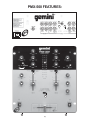
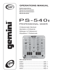
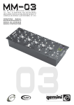
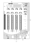
OPERATORS MANUAL
BEDIENUNGSHANDBUCH
MANUAL DEL OPERADOR
MANUEL D’INSTRUCTIONS
PMX-500
PROFESSIONAL STEREO PREAMP MIXER
PROFESSIONNELLER STEREO VORVERSTÄRKERMISCHPULT
MEZCLADOR-PREAMPLIFICADOR ESTEREOFÓNICO PARA
EL PROFESIONAL
MÉLANGEUR-PRÉAMPLIFICATEUR STÉRÉOPHONIQUE POUR
LE PROFESSIONNEL
MISCELATORE-PREAMPLIFICATORE STEREOFONICO PER
IL PROFESSIONALE
MULTI-LANGUAGE INSTRUCTIONS:
ENGLISH................................................................................................................................PAGE 3
DEUTSCH..............................................................................................................................PAGE 4
ESPAÑOL...............................................................................................................................PAGE 5
FRANCAIS.............................................................................................................................PAGE 6
(1)
PMX-500 FEATURES:
3
4
5
9
6
7
2
3
4
5
10
11
10
11
8
6
1
14
15
21
16
22
20
37
31
17
23
18
24
34
30
32
33
35
19
36
25
29
27
28
28
26
12
13
(2)
4. CROSSFADER SECTION: The CROSSFADER (26) allows the mixing
INTRODUCTION:
of one source into another. The left side of the CROSSFADER (26) is
CHANNEL 1 and the right side is CHANNEL 2. The CROSSFADER (26)
in your unit is removable and if the need arises can be easily replaced.
Your Gemini mixer comes with an RG-45 PRO (RAILGLIDE™) DualRail Crossfader. RAIL GLIDE™ crossfaders have internal dual
stainless steel rails that allow the slider to ride smoothly and accurately
from end to end. Also available is our CF-45 PRO (PROGLIDE™) DualRail Crossfader. This unique crossfader features, state of the art
conductive plastic technology, for unlimited useage. Another
crossfader we have available is the PSF-45 (PRO SCRATCH™)
crossfader with a special curve designed for scratch mixing. Just
purchase one from your Gemini dealer and follow the instructions:
Congratulations on purchasing the Gemini PMX-500 mixer. This state
of the art mixer includes the latest features and is backed by a three
year limited warranty, excluding crossfader and channel slides. Prior
to use, we suggest that you carefully read all the instructions.
FEATURES:
•
•
•
•
•
•
2 Stereo channels
2 Phono/Line Convertible, 1 Phono, 1 Line and 1 Mic input
1/4" DJ Mic jack
Bass, Mid, High and Gain controls on each channel
Master output control
Cue section
1. Unscrew the outside FADER PLATE SCREWS (B).
Do not touch the INSIDE SCREWS (C).
2. Carefully lift the fader and unplug the CABLE (D).
CAUTIONS:
3. Plug the new fader into the cable and place it
back in the mixer.
1. All operating instructions should be read before using this equipment.
4. Screw the fader to the mixer.
2. To reduce the risk of electrical shock, do not open the unit. There are
NO USER REPLACEABLE PARTS INSIDE. Please refer servicing to a
qualified service technician.
5. The CROSSFADER REVERSE SWITCH (27) allows you to reverse the
crossfader so that CHANNEL 2 is controlled by the left side of the
crossfader and CHANNEL 1 is controlled by the right side of the crossfader.
In the U.S.A., if you have any problems with this unit, call 1-732-7389003 for customer service. Do not return equipment to your dealer.
NOTE: WHEN THE CROSSFADER REVERSE SWITCH (27) IS ACTIVATED
(MOVED TO THE RIGHT), ONLY THE CROSSFADER REVERSES. THE
CHANNEL SLIDES, GAIN, AND TONAL CONTROLS DO NOT REVERSE.
3. Do not expose this unit to direct sunlight or to a heat source such as a
radiator or stove.
6. PUNCH IN: The PUNCH IN BUTTONS (28) allow you to add a channel’s
signal to the mix when the crossfader is set to the opposite channel.
4. This unit should be cleaned only with a damp cloth. Avoid solvents or
other cleaning detergents.
7. OUTPUT CONTROL SECTION: The level of the MASTER OUTPUT (3)
is controlled by the MASTER (29) control.
5. When moving this equipment, it should be placed in its original carton
and packaging. This will reduce the risk of damage during transit.
NOTE: THE RECORD OUT (4) HAS NO LEVEL CONTROL. THE LEVEL IS SET
BY THE CHANNEL SLIDES AND THE GAIN CONTROLS OF THE SELECTED
CHANNEL. THE TONAL QUALITIES ARE SET BY THE BASS, MID AND
HIGH CONTROLS OF THAT SAME CHANNEL.
6. DO NOT EXPOSE THIS UNIT TO RAIN OR MOISTURE.
8. TALKOVER SECTION: The purpose of the TALKOVER section is to
allow the program playing to be muted so that the MIC can be heard
above the music. The MIC/TALKOVER (30) switch has three settings.
When the MIC/TALKOVER (30) switch is in the left position, the MIC
and TALKOVER are both off. When the MIC/TALKOVER (30) switch
is in the center position the MIC is on, the MIC INDICATOR (31) will
glow, but talkover is off. When the MIC/TALKOVER (30) switch is in
the right position, the MIC and TALKOVER will be on and the volume of
all sources except the MIC input are lowered by 16 dB. MIC LEVEL
(33) controls the level of the MIC. The MIC EQ (32) control allows you to
fully adjust the tone of the MIC.
7. DO NOT USE ANY SPRAY CLEANER OR LUBRICANT ON ANY
CONTROLS OR SWITCHES.
CONNECTIONS:
1. Before plugging in the 15V AC Adapter into the POWER JACK (2) on
rear panel, make sure that the POWER (1) switch is in the off position.
2. The PMX-500 is supplied with 2 sets of output jacks. The MASTER
OUTPUT (3) jacks are used to connect to your main amplifier. The
REC OUTPUT (4) jacks can be used to connect the mixer to the record
input of your recorder enabling you to record your mix.
9. CUE SECTION: By connecting a set of headphones to the HEADPHONE
JACK (13), you can monitor either channel or both together. Move the
CUE SWITCH (34) to the left to monitor CHANNEL 1. Move the CUE
SWITCH (34) to the right to monitor CHANNEL 2. By rotating the CUE
PGM PAN (35) control to the left you will be able to monitor the assigned
cue signal. Rotating to the right will monitor the PGM (program) output.
Use the CUE LEVEL (36) control to adjust the headphone volume without
affecting the overall mix.
3. The DJ MIC (12) input (found on the front panel) accepts a 1/4"
connector and accepts balanced and unbalanced microphones.
4. On the rear panel are 2 stereo PHONO/LINE (6, 10) inputs, 1 stereo
PHONO (11) input and 1 stereo LINE (5) input. The PHONO/LINE
SWITCHES (7, 8) enable you to set the (6, 10) inputs to Phono or
Line. The Phono inputs will accept only turntables with a MAGNETIC
CARTRIDGE. A GROUND SCREW (9) for you to ground your
turntables is located on the rear panel. The stereo line inputs will
accept any line level input such as a CD player, a cassette player, etc.
10.DISPLAY: DISPLAY (37) indicates the MASTER OUTPUT (3) left and right
levels, as controlled by the MASTER (29) level.
SPECIFICATIONS:
5. Headphones plug into the front panel mounted HEADPHONE (13) jack.
INPUTS:
DJ Mic........................................................................................1.5 mV 2 kOhm
Phono @1kHz...............................................................................2 mV 47 kOhm
Line.........................................................................................100 mV 10 kOhm
OPERATION:
1. POWER ON: Once you have made all the equipment connections to
your mixer, press the POWER (1) switch.
OUTPUTS:
Amp.........................................................................................0 dB 1V 400 Ohm
Max-18V Peak to Peak
2. CHANNEL 1: The GAIN (14), HIGH (15), MID (16), and BASS (17)
controls allow you to fully adjust the selected source. SWITCH # (18)
allows you to select either the PHONO 1 (11) or the PHONO 2/LINE 1 (10)
input. The CHANNEL SLIDE (19) controls the output level of this channel.
GENERAL:
BASS (Channels 1-2)......................................................................+ 12 dB/-32 dB
Mid (Channels 1-2).........................................................................+ 12 dB/-32 dB
High (Channels 1-2).......................................................................+ 12 dB/-32 dB
Gain (Channels 1-2)............................................................................0 to -20 dB
Frequency Response...........................................................20 Hz-20 kHz +/- 2 dB
Distortion....................................................................................less than 0.02%
S/N Ratio..................................................................................better than 80 dB
Talkover Attenuation..................................................................................-16 dB
Power Source...............................................................Adapter-115V/15V AC 0.5A
..........................................................................................or 230V/15V AC 0.5A
Dimensions...............................................10” x 10.24” x 3.3” (254 x 260 x 84 mm)
Weight..........................................................................................6.25 lbs (3 kg)
3. CHANNEL 2: The GAIN (20), HIGH (21), MID (22), and BASS (23)
controls allow you to fully adjust the selected source. SWITCH #
(24) allow you to select either the PHONO 3/LINE 2 (6) or the LINE 3
(5) input. The CHANNEL SLIDE (25) controls the output level of this
channel.
NOTE: THERE IS BASS, MID AND HIGH EQUALIZATION FOR EACH CHANNEL
WITH AN EXTREMELY WIDE RANGE OF ADJUSTMENT GIVING YOU A
SMOOTHER MIX.
Specifications and designs are subject to change without notice for the purpose of improvement.
(3)
4. ÜBERBLENDER-BEREICH: Der CROSSFADER (26) ermöglicht das Mischen von
Tonquellen. Die linke Seite des CROSSFADER (26) ist Kanal 2 und die rechte ist
Kanal 3. Der CROSSFADER (26) Ihres Geräts kann entfernt werden und läßt sich
bei Bedarf leicht ersetzen. Überblender sind in drei Größen verfügbar. Der RG-45
PRO (RAIL GLIDETM) Dual-Rail Crossfader. Die Rail Glide™ Überblender
enthalten innere Schienen aus rostfreiem Stahl, die dem Benutzer ermöglichen,
den Überblender sanft und genau von der einen zur anderen Seite zu schieben.
Auch ist unser CF-45 PRO (PROGLIDE™) Dual-Rail Crossfadervorhanden.
Dieses einzigartige Überblender Eigenschaften, Zustand der kunstleitenden
Plastiktechnologie, für unbegrenztes useage. Ein anderes Überblender, das wir
haben ist Teile-Nr. PSF-45 mit einer Spezialkrümmung für Raspelmischen
verfügbar. Sie können einen dieser Überblender bei Ihrem Gemini-Händler beziehen
und diese Anweisungen befolgen:
EINLEITUNG:
Wir gratulieren Ihnen zum Kauf eines Gemini PMX-500 Mischpults. Dieses
moderne Mischpult enthält die neuesten Funktionen mit dreijähriger Garantie,
ausscheließlich crossfader und Kanalschieber. Vor Anwendung dieses Mischpults
bitte alle Anweisungen sorgfältig durchlesen.
FUNKTIONEN:
• 2 Stereokanäle
• 2 konvertierbare Eingänge für Phonoleitungen/Leitung,
Eingänge für 1 Phonoleitungen, Eingänge für 1 Leitungen,
Eingang für 1 Mikrophon
• Buchse für DJ Mikrophon (1/4")
• Steuerungen für Tiefton, Mitte, Hochton und
Verstärkungsfaktor für jeden Kanal
• Ausgänge für Master mit regler/Cue
• Symmetrische und unsymmetrische Hauptausgänge
1. Die äußeren SCHRAUBEN DER ÜBERBLENDERPLATTE (B) losschrauben.
Nicht die INNENSCHRAUBEN (C) losschrauben.
2. Den Überblender vorsichtig anheben und das
KABEL (D) herausziehen.
3. Den neuen Überblender in das Kabel hineinfügen und
wieder in das Mischpult setzen.
VORSICHTSMAßNAHMEN:
4. Den neuen Überblender mit den
Schrauben am Mischpult befestigen.
1. Vor Anwendung dieses Geräts bitte alle Anweisungen sorgfältig durchlesen.
5. Der CROSSFADER REVERSE SWITCH (27) ermöglicht den Rückwärtsgang des
Crossfaders KANAL 2 wird nun kontrolliert durch die linke Seite des Crossfader
und KANAL 1 durch die rechte Seite.
2. Das Gerät nicht öffnen, um das Risiko elektrischen Schocks zu vermeiden. Es
enthält KEINE VOM ANWENDER ERSETZBAREN TEILE. Die Wartung darf nur
von befähigten Wartungstechnikern durchgeführt werden.
HINWEIS: IST DER CROSSFADER REVERSE-SCHALTER (31) AKTIVIERT
(NACH RECHTS GESCHOBEN), LÄUFT NUR DER ÜBERBLENDER IN
GEGENRICHTUNG. DIE KANAL-SCHIEBEREGLER, TONSTÄRKE- UND
ÜBERBLENDERSCHALTER SOWIE DIE TONREGLER LAUFEN NICHT IN
GEGENRICHTUNG.
Falls Sie in den USA irgendwelche Probleme mit Ihrem Gerät haben, wenden Sie sich an den
Gemini-Kundendienst unter 1-732-738-9003. Das Gerät bitte nicht an Ihren Händler zurückschicken.
3. Das Gerät von direktem Sonnenlicht oder einer Wärmequelle wie Heizkörper oder
Ofen aussetzen.
6. PUNCH IN: Die Taste PUNCH IN (28) ermöglicht Ihnen, ein Signal eines Kanals
dem Tongemisch hinzuzufügen, wenn der Überblender auf den gegenüberleigenden
Kanal eingestellt ist.
4. Dieses Gerät darf nur mit einem feuchten Tuch gesäubert werden. Keine
Lösungs-oder Reinigungsmittel benutzen.
7. AUSGANGSREGELUNG: Der Pegel des MASTER OUTPUT (3) wird mittels der
Steuervorrichtung MASTER (29) gesteuert.
5. Bei Umzügen sollte das Gerät in seinem ursprünglichen Versandkarton und
Verpackungsmaterial verpackt werden. Dadurch verhindert man, daß das Gerät
während des Transportes beschädigt wird.
HINWEIS: DER AUFZEICHNUNGSAUSGANG RECORD OUT (4) IST NICHT MIT
PEGELSTEUERUNG AUSGERÜSTET. DER PEGEL WIRD MITTELS
KANALSCHIEBERN UND DER VERSTÄRKUNGSFAKTORSTEUERUNG DES
AUSGEWÄHLTEN KANALS EINGESTELLT. DIE TONQUALITÄT WIRD
MITTELS DER STEUERVORRICHTUNGEN TIEFTON, MITTE UND HOCHTON
DESSELBEN KANALS EINGESTELLT.
6. DIESES GERÄT NICHT REGEN ODER FEUCHTIGKEIT AUSSETZEN.
7. AN DEN REGLERN ODER SCHALTERN KEIN SPRAYREINIGUNGSMITTEL ODER SCHMIERMITTEL BENUTZEN.
8. TALKOVER: Durch die TALKOVER-Funktion wird das abgespielte Programm
gedämpft, um eine Ansage über das Mikrophon hören zu können. Der Schalter
MIC/TALKOVER (30) hat drei Einstellungen. Wenn der Schalter MIC/TALKOVER
(30) in der links Position steht, sind MIC und TALKOVER beide ausgeschaltet.
Steht der Schalter MIC/TALKOVER (30) in der mittleren Position, ist MIC
eingeschaltet. Der MIC-ANZEIGER (31) ist erleuchtet, jedoch ist TALKOVER
ausgeschaltet. Wenn der Schalter MIC/TALKOVER (30) in der rechts Position
steht, sind MIC und TALKOVER eingeschaltet, und Lautstärken aller Tonquellen,
außer des MIC-Eingangs, werden um 16 dB reduziert. MIC LEVEL (33) reguliert
die Tonstärke von MIC. Der Regler MIC EQ (32) ermöglicht Ihnen, den Ton von
MIC vollständig zu regulieren.
ANSCHLÜSSE:
1. Vor der Verstopfung im Wechselstrom 15V Adapter in die POWER JACK (2) auf
Rückwandblech, überprüfen Sie, ob der POWER (1) Schalter in der
Ausschaltstellung ist.
2. Beim Mischpult PMX-500 sind 2 Sätze von Ausgangsanschlüssen vorgesehen.
Die Anschlüsse MASTER OUTPUT (3) (Verkstärkerausgang) dienen zum
Anschließen des Hauptverstärkers. Die Anschlüsse REC OUTPUT (4)
(Aufzeichungsausgang) können dazu verwendet werden, das Mischpult an
den Aufzeichnungseingang des Rekorders anzuschließen, um die Mischung
aufzuzeichnen.
9. CUE: Indem Sie die Kopfhörer an der KOPFHÖRER-Buchse (13) anschlieben,
können Sie einen oder beide Kanäle zusammen überwachen. Den CUE-SCHALTER
(34) nach links schieben, um KANAL 1 zu überwachen. Den CUE-SCHALTER (34)
nach rechts schieben, um KANAL 2 zu überwachen. Indem Sie den Regler CUE
PGM PAN (35) nach links drehen, können Sie das zugewiesene Mithörsignal
kontrollieren. Nach rechts drehen wird die PGM-(Programm) Ausgabe kontrolliert.
Mit Hilfe des CUE-PEGEL-Reglers (36) kann die Kopfhörerlautstärke eingestellt
werden, ohne dabei die allgemeine Tonmischung zu beeinträchtigen.
3. Der Eingang DJ MIC (12) (an der Vorderseite) nimmt Anschlüsse mit Durchmesser
von 0,38 mm (1/4"), und balancierte und unbalancierte Mikrophone auf.
4. An der Rückwand sind jeweils 2 Stereoeingänge PHONO/LINE (6, 10),
1 Stereoeingänge für PHONO (11) und 1 LEITUNG-LINE (5) angebracht. Die
Schalter PHONO/LINE SWITCHES (7, 8) ermöglichen Ihnen, die Eingänge (6, 10)
an Phono oder Line anzuschließen. Die Phono-Eingänge werden nur Plattenspieler
mit einem magnetischem Tonabnehmer aufnehmen. Eine Erdungschraube
GROUND SCREW (9) zur Erdung des Plattenspielers ist an der Rückwand
angebracht. Die Stereo-Leitungseingängen nehmen Geräte wie CD-oder
Kassettenspieler auf.
10. ANZEIGE: Die ANZEIGE - DISPLAY (37) zeigt den REGIEPULT-AusgangspegelMASTER (3) links und rechts an aus das MASTER (29).
SPEZIFIKATIONEN:
EINGÄNGE:
DJ-Mikrophon...............................................................................1.5 mV 2 kOhm
Phono......................................................................................... 2 mV, 47 kOhm
Leitung.....................................................................................100 mV, 10 kOhm
5. Kopfhörer können an der an der Vorderwand montierten Kopfhörer-Buchse
HEADPHONE (13) eingesteckt werden.
AUSGÄNGE:
Amp........................................................................................0 dB 1 V 400 Ohm
Max-18V Spitze-Spitze
BEDIENUNG:
ALLGEMEINES:
Tiefenregler (Kanäle 1-2).................................................................+ 12 dB/-32 dB
Mittenregler (Kanäle 1-2)................................................................. + 12 dB/-32 dB
Höhenregler (Kanäle 1-2).................................................................+ 12 dB/-32 dB
Tonstärkenregler (Kanäle 1-2)...............................................................0 bis -20 dB
Frequenzgang....................................................................20 Hz-200 kHz +/- 2 dB
Klirrfaktor...............................................................................................< 0,02%
Störabstand................................................................................besser als 80 dB
Talkover-Dämpfung...................................................................................-16 dB
Stromversorgung..........................................................Adapter-115V/15V AC 0.5A
..........................................................................................or 230V/15V AC 0.5A
Abmessungen.........................................................................254 x 260 x 84 mm
Gewicht.......................................................................................................3 kg
1. STROM EIN: Nachdem Sie das Gerät am Mischpult angeschlossen haben,
drücken Sie auf die Taste POWER (1).
2. KANAL 1: Die Regelelemente GAIN (14), HIGH (15), MID (16), und BASS (17)
ermöglichen ein vollkommenes Regulieren der ausgewählten Tonquelle.
SCHALTER # (18) ermöglicht, den Eingang von PHONO 1 (11) oder PHONO 2/
LINE 1 (10) auszuwählen. CHANNEL SLIDE (19) regelt den Ausgangstonsignal
dieses Kanals.
3. KANAL 2: Die Regelelemente GAIN (20), HIGH (21), MID (22) und BASS (23)
ermöglichen ein vollkommenes Regulieren der ausgewählten Tonquelle. SCHALTER #
(24) ermöglicht, den Eingang von PHONO 3/LINE 2 (6) oder LINE 3 (5) auszuwählen.
CHANNEL SLIDE (25) regelt den Ausgangstonsignal dieses Kanals.
Die Spezifikationen können zu Verbesserungszwecken ohne vorherige Bekanntgabe geändert werden.
HINWEIS: FÜR JEDEN KANAL GIBT ES NIEDRIGE (BASS), MITTLERE (MID) UND
HOHE (HIGH) ENTZERRUNG MIT EINEM ÄUßERST BREITEN
REGULIERBEREICH, WELCHES EINE GLEICHFÖRMIGERE MISCHUNG BIETET.
(4)
INTRODUCCIÓN:
4. SECCIÓN DE ATENUADOR DE TRANSFERENCIA: El CROSSFADER (26)
permite la mezcla de una fuente con otra. El lado izquierdo del CROSSFADER (26)
corresponde al canal 2 y el lado derecho al canal 3. El CROSSFADER (26) de su
aparato es removible y, en caso de necesidad, su reemplazo es fácil. Se ofrecen
unidades de atenuador de transferencia de tres tamaños. La RG-45 PRO (RAIL
GLIDETM) Dual-Rail Crossfader. Estos crossfaders contienen dos rieles internos
de acero inoxidable que permiten al deslizador de moverse sin problema y con
precisión de una extremidad a otra. También disponible está nuestro Cf-45 PRO
(PROGLIDE™) Dual-Rail Crossfader. Características únicas de este
crossfader, tecnología plástica conductora avanzada, para el useage ilimitado.
Otro crossfader que tenemos disponible es el crossfader Psf-45 (PRO
SCRATCH™) con curva especial diseñada para mezclar el efecto de frotamiento.
Simplemente compre cualquiera de estas unidades de atenuador de transferencia
de su distribuidor Gemini y siga las instrucciones siguientes:
Felicitaciones por su compra del mezclador PMX-500 de Gemini. Este mezclador
de la más avanzada tecnología está dotado de características ultramodernas y
está respaldado por una garantía de tres años, salvo el crossfader y los mandos
corredizos de canal. Antes de usarlo, le recomendamos leer cuidadosamente
todas las instrucciones.
CARACTERÍSTICAS:
• 2 canales estereofónicos
• 2 entradas fono/línea convertibles, 1 entrada de fono, 1 entrada
de línea, y 1 entrada para micrófono
• Jack para micrófono DJ tipo 1/4 de pulgada
• Controles de tonos Bajos, Medios y Agudos y de Ganancia en cada canal
• Salidas para maestras con la llave corrediza maestra
• Seccion de referencia
• Salidas principales equilibradas y desequilibradas
1. Destornille los TORNILLOS EXTERIORES de la PLACA DEL ATENUADOR (B).
No toque LOS TORNILLOS INTERNOS (C).
2. Levante cuidadosamente el atenuador y desenchufe
el CABLE (D).
PRECAUIONES:
3. Conecte el nuevo atenuador al cable y póngalo de
nuevo dentro del mezclador.
1. Deberán leerse todas las instrucciones de operación antes de usar el equipo.
4. Atornille el atenuador en el mezclador.
2. Para reducir el riesgo de shock eléctrico, no abra esta unidad. No contiene
PIEZAS REEMPLAZABLES POR EL USUARIO. Por favor, refiera el servicio a
un técnico de servicio calificado.
5. El CROSSFADER REVERSE SWITCH (27) le permite invertir el crossfader; asi el
CANAL 2 será mandado por el lado izquierdo del crossfader y el CANAL 1 lo será
por el lado derecho del crossfader.
En los EE.UU., si Ud tiene problemas con el aparato, por favor llame al Servicio Post-Venta al
1-732-738-9003. No devuelva el aparato a la tienda donde lo compró.
NOTA: CUANDO SE ACTIVA EL CROSSFADER REVERSE SWITCH (31),
SOLAMENTE SE PRODUCE LA INVERSIÓN DEL CROSSFADER. NO SE
PRODUCE EN LOS CURSORES CORREDIZOS DE CANALES, EN EL GAIN, EN
LOS INTERRUPTORES KILL Y EN LOS MANDOS DE TONALIDAD.
3. No exponga la unidad a la luz solar directa ni a una fuente de calor, por ejemplo,
un radiador o estufa.
6. PUNCH IN: El botón PUNCH IN (28) le permite añadir la señal de un canal a la
mezcla cuando el atenuador de transferencia está arreglado para el canal opuesto.
4. Esta unidad sólo deberá limpiarse con un paño húmedo. Evite el uso de
disolventes u otros detergentes de limpieza.
7. SECCIÓN DE CONTROL DE LA SALIDA: El nivel de la salida del amplificador
MASTER OUTPUT (3) se controla con la llave corrediza maestra MASTER (29).
5. Para mover este equipo, colóquelo en la caja y empaque original, a fin de reducir
el riesgo de daños durante el transporte.
NOTA: LA SALIDA RECORD OUT (4) NO TIENE CONTROL DE VOLUMEN. EL NIVEL
LO DETERMINAN LAS LLAVES CORREDIZAS DE CANAL Y EL CONTROL DE
GANANCIA DEL CANAL SELECCIONADO. LAS CARACTERÍSTICAS TONALES
SON DETERMINADAS POR LOS CONTROLES DE TONOS BAJOS, MEDIOS Y
ALTOS DEL MISMO CANAL.
6. NO DEJE ESTA UNIDAD EXPUESTA A LLUVIA O HUMEDAD.
7. NO USE LIMPIADORES DE ROCÍO O LUBRICANTES EN CUALESQUIER
CONTROLES O INTERRUPTORES.
8. SECCIÓN TALKOVER: El propósito de la sección talkover es de permitir al
programa de ponerse sordina para que se pueda oír el mensaje del micrófono por
encima de la música. El interruptor MIC/TALKOVER (30) tiene tres arreglos.
Cuando el interruptor MIC/TALKOVER (30) ocupa la posición izquierda, el MIC y la
función talkover están ambos apagados. Cuando el interruptor MIC/TALKOVER
(30) ocupa la posición central, el MIC está activado, el INDICADOR MIC (31) se
prenderá pero la función talkover está apagada. Cuando el interruptor MIC/
TALKOVER (30) ocupa la posición derecha, el MIC y la función talkover estarán
prendidos y el volumen de todas las fuentes salvo las entradas MIC serán
reducidas por 16 dB. El MIC LEVEL (33) controla el volumen del micrófono. El
mando MIC EQ (32) le permite ajustar completamente el tono del MIC.
CONEXIONES:
1. Antes de tapar en el ADAPTADOR de la CA 15V en el gato de la POWER
JACK (2) en panel trasero, cerciórese de que el interruptor de la POWER (1)
está en la posición de reposo.
2. El aparato PMX-500 incorpora juegos de receptáculos de salida. Los receptáculos
de salida a amplficador MASTER OUTPUT (3) se emplean para conectar al
amplificador principal. Los receptáculos de salida a grabadora REC OUTPUT (4)
pueden emplearse para conectar el mezclador a la entrada de grabación del
grabador, lo que permite grabar la mezcla.
9. SECCIÓN CUE: Al conectar audífonos al jack de HEADPHONE (13), se puede
monitorear el CANAL 1, el CANAL 2 o ambos a la vez. Mueva el CUE SWITCH
(34) a la izquierda para monitorear el CANAL 1. Mueva el CUE SWITCH (34) a la
derecha para monitorear el CANAL 2. Girando el control CUE PGM PAN (35) hacia
la izquierda, Ud podrá monitorear la señal cue asignada. Girándolo a la derecha,
podrá monitorear la salida del PROGRAMA (PGM). Utilice el mando del CUE
LEVEL (36) para ajustar el volumen del audífono sin afectar la mezcla global.
3. La entrada DJ MIC (12) (que se encuentra en el panel delantero) acepta conector
de 1/4 de pulgada y micrófonos equilibrados y no equilibrados.
4. En el panel trasero hay 2 entradas estereofónicas PHONO/LINE (6, 10 ), 1
entrada estereofónica de FONÓGRAFO- PHONO (11) y 1 entrada estereofónica
de LINE (5). Los conmutadores PHONO/LINE SWITCHES (7, 8) le permiten
arreglar las entradas (6, 10) a Phono o Line (fonográfico o línea). Las entradas
fonográficas solamente aceptarán giradiscos con cartucha magnética. Un
GROUND SCREW (9) para poner el giradiscos a tierra se encuentra en el panel
trasero. Las entradas de línea estereofónicas aceptarán cualquier entrada de
nivel de línea tal como tocadisco de discos compactos o casetera, etc.
10. DISPLAY : El visualizador DISPLAY (37), indica los niveles de salida derecha e
izquierda del control MASTER LEVEL (29).
ESPECIFICACIONES TÉCNICAS:
ENTRADAS:
Micrófono DJ...............................................................................1.5 mV 2 kOhm
Fonógrafo.................................................................................2 mV 47 Kohmios
Línea....................................................................................100 mV 27 Kohmios
5. Los audífonos se enchufan en el jack de HEADPHONE (13) (audífonos) montado
en el panel delantero.
FUNCIONAMIENTO:
SALIDAS:
Amplificador.........................................................................0 dB 1 V 400 ohmios
Máx-18V pico-pico
1. ENCENDIDO: Una vez que haya efectuado todas las conexiones de los equipos
a su mezclador, oprima el INTERRUPTOR DE ENERGÍA-POWER (1).
2. CANAL 1: Los mandos de GAIN (14) (ganancia), HIGH (15) (alto), MID (16)
(mediano) y BASS (17) (bajo) le permiten arreglar plenamente la fuente
seleccionada. El INTERRUPTOR # (18) le permite seleccionar la entrada PHONO
1 (11) o PHONO 2/LINE 1 (10). El CHANNEL SLIDE (19) (cursor corredizo de
canal) controla el volumen de salida de este canal.
GENERALES:
Bass (canales 1-2).........................................................................+ 12 dB/-32 dB
Medianos (canales 1-2)...................................................................+ 12 dB/-32 dB
Altos (canales 1-2).........................................................................+ 12 dB/-32 dB
Ganancia (canales 1-2).....................................................................de 0 a -20 dB
Respuesta de frecuencia.......................................................20 Hz-20 kHz +/- 2dB
Distorsión..............................................................................................< 0,02%
Relación señal/ruido.....................................................................superior a 80 dB
Atenuación talkover...................................................................................-16 dB
Fuente de energía.........................................................Adapter-115V/15V AC 0.5A
..........................................................................................or 230V/15V AC 0.5A
Dimensiones...........................................................................254 x 260 x 84 mm
Peso...........................................................................................................3 kg
3. CANAL 2: Los mandos de GAIN (20) (ganancia), HIGH (21) (alto), MID (22)
(mediano) y BASS (23) (bajo) le permiten arreglar plenamente la fuente
seleccionada. El interruptor # (24) le permite seleccionar la entrada PHONO 3/
LINE 2 (6), o LINE 3 (5). El CHANNEL SLIDE (25) (cursor corredizo de canal)
controla el volumen de salida de este canal.
NOTA: EXISTE IGUALACIÓN DE LOS TONOS BAJOS, MEDIANOS Y ALTOS PARA
CADA CANAL CON MUY AMPLIO ALCANCE DE AJUSTE LO QUE LE PERMITE
OBTENER MEJOR MEZCLA.
Las especificaciones y el diseño pueden cambiar sin preaviso por razones de mejoras.
(5)
INTRODUCTION:
4. SECTION CROSSFADER: Le CROSSFADER (26) permet le mélange d’une source
avec une autre Le côté gauche du CROSSFADER (26) est la voie 2 et le côté droit est la
voie 3. Le CROSSFADER (26) de votre appareil est amovible et s’il le faut, il est
facilement remplacé. Des appareils crossfader sont
disponibles en
trois genres. La RG-45 PRO (RAIL GLIDETM) Dual-Rail Crossfader. Ces crossfaders
comportent à l’intérieur deux voies en inox qui permettent au coulisseur de se
déplacer aisément et avec précision d’une extrémité à l’autre. En outre disponible
est notre Cf-45 PRO (PROGLIDE™) Dual-Rail Crossfader. Dispositifs uniques de
ce crossfader, technologie en plastique conductrice du dernier cri, pour l’useage
illimité. Un autre crossfader que nous avons disponible est le crossfader Psf-45
(PRO SCRATCH™) avec courbe spéciale conçue pour le mélange de l’effet de
frottement. Il suffit d’acquérir un de ces genres auprès de votre concessionnaire Gemini et
de suivre les instructions suivantes:
Nos félicitations à l’occasion de votre achat du mélangeur PMX-500 de Gemini.
Ce mélangeur très moderne inclut les caractéristiques technologiques les plus
récentes et il est accompagné d’une garantie de trois ans, à l’exclusion du
crossfader et des curseurs de canal. Avant de vous en servir, lisez attentivement
toutes les instructions ci-après.
CARACTÉRISTIQUES:
• 2 canaux stéreo
• 2 entrées phono/ligne convertibles, 1 entrée phono, 1 entrée ligne et 1
entrée micro
• Jack for micro d’animateur à raccord 1/4 de pouce
• Basse, médiane, aigu et réglage du gain sur chaque canal
• Sorties principales et la commande master/ Cue
• Sorties principales équilibrées et déséquilibrées
1. Dévissez les VIS externes DE LA PLAQUE DE L’ATTÉNUATEUR (B).
Ne touchez pas aux VISSES INTERNES (C).
2. Soulevez soigneusement l’atténuateur et
débranchez le CÂBLE (D).
AVERTISSEMENTS:
3. Branchez le nouvel atténuateur au câble et
replacez-le dans le mélangeur.
1. On devrait lire toutes les consignes d’exploitation avant d’utiliser ce matériel.
4. Vissez l’atténuateur au mélangeur.
2. Afin de réduire le risque de choc électrique, n’ouvrez pas l’appareil. Il n’y a pas de
PIÈCES REMPLAÇABLES À L’INTÉRIEUR. Veuillez soumettre l’entretien/la
réparation à un technicien qualifié.
5. Le CROSSFADER REVERSE SWITCH (34) vous permet de renverser le
crossfader; ainsi le CANAL 2 ser commandé par le côté gauche du crossfader et
le CANAL 1 par le côté droit du crossfader.
Aux États-Unis, si vous cet appareil vous donne des problèmes, appelez le Service Après-Vente
au 1-732-738-9003. Ne renvoyez pas l’appareil au détaillant.
REMARQUE: LORSQUE LE CROSSFADER REVERSE SWITCH (31) EST ACTIVÉ
(DÉPLACÉ À DROITE), SEUL LE CROSSFADER SERA RENVERSÉ. LES
CURSEURS COULISSANTS DES CANAUX, LE GAIN, LES INTERRUPTEURS
KILL ET LES COMMANDES DE TONALITÉ NE SONT PAS RENVERSÉS.
3. Ne pas exposer cet appareil aux rayons du soleil direct ou à une source de
chaleur telle qu’un radiateur ou un poêle.
4. Cet appareil devrait être nettoyé seulement avec un chiffon humide. Evitez les
solvants et autres détergents de nettoyage.
6. PUNCH IN: El botón PUNCH IN (28) le permite añadir la señal de un canal a la
mezcla cuando el atenuador de transferencia está arreglado para el canal opuesto.
5. Quand on déplace ce matériel, il devrait être mis dans son carton et son
emballage d’origine. Ceci réduira le risque de dégâts pendant le transport.
7. SECTION OUTPUT CONTROL: Le niveau de MASTER OUTPUT (3) est
commandé par la commande MASTER (29).
6. NE PAS EXPOSER CET APPAREIL À LA PLUIE OU À L’HUMIDITÉ.
NOTE: LE RECORD OUT (4) (ENREGISTREMENT SORTIE) N’A PAS DE
COMMANDE DE NIVEAU. LE NIVEAU EST RÉGLÉ PAR LES GLISSIÈRES DE
CANAL ET LA COMMANDE DE GAIN DU CANAL CHOISI. LES QUALITÉS
DES SONS SONT DÉTERMINÉES PAR LES COMMANDES DE BASSE, DE
MÉDIANE ET D’AIGU DE CE MÊME CANAL.
7. N’UTILISEZ PAS DE PRODUIT DE NETTOYAGE AVEC VAPORISATEUR OU
LUBRIFIANT SUR AUCUN DES BOUTONS OU DES INTERRUPTEURS.
CONNEXIONS:
8. SECTION TALKOVER: Le propos de cette section est de permettre au
programme en marche d’être assourdi de sorte que le message transmis par le
micro puisse être entendu par-dessus la musique. Le MIC/TALKOVER (30)
comporte trois réglages. Lorsque le MIC/MIC/TALKOVER (30) occupe la position
de gauche, le MIC et la fonction talkover sont au repos. Lorsque le MIC/
TALKOVER (30) occupe la position centrale, le MIC est sous tension, le MIC
INDICATOR (31) s’allumera mais la fonction talkover est au repos. Lorsque le
MIC/TALKOVER (30) occupe la position droite, le MIC et la fonction talkover
seront activés et le volume de toutes les sources, sauf les entrées MIC, sera
réduit de 16 dB. Le MIC LEVEL (33) commande le volume du microphone. La
commande MIC EQ (32) vous permet d’ajuster entièrement le ton du MIC.
1. Avant le branchement dans l’ADAPTEUR à C.A. 15V dans le cric de POWER
JACK (2) sur le panneau arrière, assurez-vous que le commutateur de la POWER
(1) est dans la position de repos.
2. Le PMX-500 est fourni avec 2 jeux de jacks de sortie. Les jacks de MASTER
OUTPUT (3) sont utilisés pour relier à votre amplificateur principal. Les jacks de
REC OUTPUT (4) peuvent être utilisés pour relier le mélangeur à l’entrée
d’enregistrement de votre enregistreur ce qui vous permettra d’enregistrer votre
mélange.
9. SECTION CUE: En branchant des écouteurs au jack de HEADPHONE (13), vous
pouvez suivre le CANAL 1, le CANAL 2 ou les deux à la fois. Déplacez le CUE
SWITCH (34) à gauche pour suivre le CANAL 1. Déplacez le CUE SWITCH (34) à
droite pour suivre le CANAL 2. En tournant la commande CUE PGM PAN (35) à
gauche, vous pourrez surveiller le signal cue assigné. Le fait de tourner à droite,
surveillera la sortie PGM (programme). Servez-vous de la commande CUE
LEVEL (36) pour ajuster le volume des écouteurs sans affecter le mélange global.
3. L’entrée DJ MIC (12) (retrouvée sur le panneau avant) accepte un connecteur de
1/4 de pouce et des microphones équilibrés et non équilibrés.
4. Sur le panneau arrière, il y a 2 entrées stéréo PHONO/LINE (6, 10), 1 entrée
PHONO (11) stéréo et 1 entrée LINE (3) stéréo. Les PHONO/LINE SWITCHES
(7, 8) (commutateurs phono/ligne) vous permettent de régler les entrées (6, 10)
sur Phono ou Line. Les entrées phono n’acceptent que des tables tournantes
avec cartouche magnétique. Une GROUND SCREW (9) (vis de terre) pour la
mise à la masse des tables tournantes est située sur le panneau arrière. Les
entrées de ligne stéréo accepteront n’importe quelle entrée de ligne telle que CD
player, cassette player, etc.
10. DISPLAY: DISPLAY (37) indique les volumes de sortie du côté gauche et du côté
droit du MASTER LEVEL (29).
CARACTÉRISTIQUES TECHNIQUES:
ENTRÉES:
DJ Mic........................................................................................1.5 mV 2 kOhm
Phono..........................................................................................2 mV 47 kOhm
Ligne........................................................................................100 mV 27 kOhm
5. Les écouteurs peuvent être branchés au jack HEADPHONE (13) que l’on retrouve
sur le panneau avant.
FONCTIONNEMENT:
SORTIES:
Amplificateur.............................................................................0 dB 1V 400 Ohm
Maxi-18V crête-crête
1. POWER ON: Dès que tous les branchements sont effectués à votre mélangeur,
appuyez sur le POWER (1) (touche de mise sous tension).
2. CANAL 1: Les commandes GAIN (14), HIGH (15) (élevé), MID (16) (moyen) et
BASS (17) (bas) vous permettent de régler entièrement la source choisie. Le
COMMUTATEUR # (18) vous permet de choisir l’entrée PHONO 1 (11) ou PHONO
2/LINE 1 (10). Le CHANNEL SLIDE (19) (curseur de canal) commande la sortie
de ce canal.
GÉNÉRALITÉS:
Basses (canaux 1-2)......................................................................+ 12 dB/-32 dB
Moyenne (canaux 1-2)....................................................................+ 12 dB/-32 dB
Hautes (canaux 1-2).......................................................................+ 12 dB/-32 dB
Gain (canaux 1-2)...........................................................................de 0 à - 20 dB
Réponse de fréquence..........................................................20 Hz-20 kHz+/- 2 dB
Distorsion..............................................................................................< 0,02%
Rapport signal/bruit....................................................................supérieur à 80 dB
Atténuation talkover...................................................................................-16 dB
Source d’énergie...........................................................Adapter-115V/15V AC 0.5A
.......................................................................................... or 230V/15V AC 0.5A
Dimensions............................................................................254 x 260 x 84 mm
Poids..........................................................................................................3 kg
3. CANAL 2: Les commandes GAIN (20), HIGH (21) (élevé), MID (22) (moyen) et
BASS (23) (bas) vous permettent de régler entièrement la source choisie. Le
COMMUTATEUR # (24) vous permet de choisir l’entrée PHONO 3/LINE 2 (6) ou
LINE 3 (5). Le CHANNEL SLIDE (25) (curseur de canal) commande la sortie de ce
canal.
NOTE: CHAQUE CANAL DISPOSE D’UNE ÉGALISATION DES BASSES, MOYENNES
ET AIGÜES AVEC UNE TRÈS GRANDE GAMME DE RÉGLAGE, CE QUI VOUS
PERMET UN MEILLEUR MÉLANGE.
Les spécifications et la conception peuvent changer sans préavis pour des raisons d’amélioration.
(6)
NOTES:
(7)
In the USA: If you experience problems with this unit,
call 1-732-738-9003 for GeminiCustomer Service.
Do not attempt to return this equipment to your dealer.
Parts of the design of this product may be protected by worldwide
patents.
Information in this manual is subject to change without notice and does
not represent a commitment on the part of the vendor. GeminiSound
Products Corp. shall not be liable for any loss or damage whatsoever
arising from the use of information or any error contained in this
manual.
No part of this manual may be reproduced, stored in a retrieval system or
transmitted, in any form or by any means, electronic, electrical,
mechanical, optical, chemical, including photocopying and recording, for
any purpose without the express written permission of GeminiSound
Products Corp.
It is recommended that all maintenance and service on this product is
performed by GeminiSound Products Corp. or its authorized agents.
GeminiSound Products Corp. will not accept liability for loss or damage
caused by maintenance or repair performed by unauthorized personnel.
Worldwide Headquarters • 120 Clover Place, Edison, NJ 08837 • USA
Tel: (732) 738-9003 • Fax: (732) 738-9006
France • G.S.L. France • 11, Avenue Leon Harmel, Z.I. Antony, 92160 Antony, France
Tel: + 33 (0) 1 55 59 04 70 • Fax: + 33 (0) 1 55 59 04 80
Germany • GeminiSound Products GmbH • Ottostrasse 6, 85757 Karlsfeld, Germany
Tel: 08131 - 39171-0 • Fax: 08131 - 39171-9
UK • GeminiSound Products • Unit C4 Hazleton Industrial Estate, Waterlooville, UK P08 9JU
Tel: 087 087 00880 • Fax: 087 087 00990
Spain • GeminiSound Products S.A. • Rosello, 516, Barcelona, Spain, 08026
Tel: 349-3435-0814 • Fax: 3493-347-6961
© GeminiSound Products Corp. 2002
(8)
All Rights Reserved