1
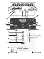
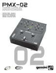
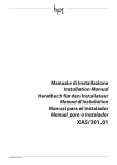
OPERATIONS MANUAL
Bedienungsanleltung
Manual de Funcionamiento
Manual de Fonctionnement
Manual del Utente
P M X -3 5 0
®
PROFESSIONAL STEREO PREAMP MIXER
Professionneller Stereo Vorverstärkermischpult
Mezclador-preamplificador estereofónico para el profesional
Mélangeur-préamplificateur stéréophonique pour le professionnel
Miscelatore-preamplificatore stereofonico per il professionale
Multi-Language Instructions
English...........................................................Page
Deutsch..........................................................Page
Español..........................................................Page
Francais.........................................................Page
Italiano.......................................................................Page
Page 1
3
4
5
6
7
123456
123456
123456
123456
123456
123456
123456
123456
123456
123456
123456
123456
123456
123456
123456
123456
123456
123456
123456
123456
123456
123456
123456
123456
12345
12345
12345
12345
12345
12345
123456
123456
123456
123456
123456
123456
123456
123456
123456
123456
123456
123456
123456
123456
123456
123456
123456
123456
123456
123456
123456
123456
123456
123456
123456
123456
123456
123456
123456
123456
1
5
4
2
6
3
8
16
7
9
6
21
10
21
22
11
13
12
13
23
21
13
24
19
17
27
24
14
13
25
24
18
19
19
20
20
26
15
26
Page 2
Introduction
®
Congratulations on purchasing a Gemini model PMX -350 mixer. Thisstate-of-the-art mixer includes the latest features and is backed by a
three year warranty, excluding crossfader and channel slides. Prior to
use, we suggest that you carefully read all the instructions.
Features
•
2 Phono/Line Convertible, 1 Phono, 1 Line and 1 Mic input
•
Gain controls for each channel
•
Removable Crossfader
•
Cue Section
Cautions
4. CROSSFADER SECTION: The CROSSFADER (20) allows the mixing of
one source into another. The left side of the CROSSFADER is
CHANNEL 1 and the right side is CHANNEL 2. The CROSSFADER in
your unit is removable and, should the need arise, can be easily
replaced. Crossfader units are available in two varieties: part RF-45
(which is identical to the crossfader supplied with this mixer) has a
45 mm travel from side-to-side, while the PSF-45 is equipped with a
special “curve” designed for scratch mixing.
To install a new crossfader:
1. Unscrew the outside FADER plate screws (B). Do not
touch the INSIDE SCREWS (C).
2. Carefully lift the fader and unplug the CABLE (D).
3. Plug the new fader into the cable and place it back in the
mixer.
4. Screw the fader to the mixer.
1. All operating instructions should be read before using this equipment.
2. To reduce the risk of electrical shock, do not open the unit. There are
NO USER REPLACEABLE PARTS INSIDE. Please refer servicing to a
qualified service technician.
In the USA: If you experience problems with this unit,
call 1 (732) 738-9003 for Gemini Customer Service.
Do not attempt to return this equipment to y
our dealer
your
dealer..
3. Do not expose this unit to direct sunlight or to a heat source such as a
radiator or stove.
4. This unit should be cleaned only with a damp cloth. Avoid solvents or
other cleaning detergents.
5. When moving this equipment, it should be placed in its original carton
and packaging. This will reduce the risk of damage during transit.
6. DO NOT EXPOSE THIS UNIT TO RAIN OR MOISTURE.
7. DO NOT USE SPRAY CLEANERS OR LUBRICANTS ON CONTROLS
OR SWITCHES.
Connections
1. Make sure that the POWER (22) switch is in the off position.
2. This unit comes supplied with a 15 volt AC adaptor. Plug the male pin
of the adaptor into the rear panel POWER JACK (6). Then plug the
adaptor into a proper power source.
3. To connect the mixer to your amplifier, use the MASTER (1) jacks on
the rear panel.
4. The unit is equipped with one microphone input. The MIC JACK (15)
is a 1/4" (6.35 mm) and is located on the front panel.
5. On the rear panel are 2 stereo PHONO/LINE (3, 4) inputs, 1 stereo
PHONO (5) input and 1 stereo LINE (2) input. The PHONO/LINE
SWITCHES (8, 9) enable you to set the (3, 4) inputs to Phono or Line.
The PHONO (5) input will accept turntable inputs only. A GROUND (7)
screw for you to ground your turntables is located on the rear panel.
The stereo LINE (2) input will accept any line level input such as a CD
player or a cassette player.
6. Headphones can be plugged into the front panel mounted
HEADPHONE (26) jack.
5. TALKOVER SECTION: The purpose of the talkover section is to allow
the program playing to be muted so that the mic can be heard above
the music. When the TALKOVER (11) button is pushed, the
TALKOVER INDICATOR (10) will glow and the volume of all sources
except MIC are reduced by -16 dB. MIC (17) controls the level of the
talkover MIC.
6. CUE SECTION: By connecting a set of headphones (26), you can
monitor either Channel 1 or Channel 2. Select Channel 1 by moving
the CUE SWITCH (19) to the left. Move to the right for Channel 2.
Use the CUE (18) control to adjust the headphone volume without
affecting the overall mix.
7. DISPLAY: The DISPLAY (16) indicates the MASTER output left and
right levels as controlled by the MASTER LEVEL (27).
Specifications
INPUTS:
Mic....................................................................................1.5mV 600 Ohm
Phono.......................................................................................3 mV 47 kOhm
Line...................................................................................150 mV 27 kOhm
OUTPUTS:
Amp................................................................................0 dB 1V 400 Ohm
Max............................20V Peak to Peak
GENERAL:
Gain (Channels 1 - 2)..................................................................0 to -20 dB
Frequency Response...........................................20 Hz - 20 kHz +/- 2 dB
Operation
Distortion...............................................................................................0.02%
S/N Ratio.........................................................................better than 80 dB
1. POWER ON: Once you have made all the equipment connections to
your mixer, press the POWER (22) switch. The power will turn on and
the POWER LED (21) will glow RED.
2. CHANNEL 1: The GAIN (12) control allows you to individually adjust
the gain of Channel 1. Switch (13) allows you to select PHONO 1 (5)
or the LINE 1/PHONO 2 (4) inputs. CHANNEL SLIDE (14) controls the
input level of this channel.
3. CHANNEL 2: The GAIN (23) control allows you to individually adjust
the gain of Channel 2. Switch (24) allows you to select the LINE 2/
PHONO 3 (3) or the LINE 3 (2) input. The CHANNEL SLIDE (25)
controls the input level of this channel.
Page 3
Talkover Attenuation.........................................................................-16 dB
Headphone Impedance..................................................................16 Ohm
Power Source.............................................................115V/15V AC 7.5 W
230V/15V AC 7.5 W
Dimensions.........................................6.5" x 9" x 3" (165 x 221 x 85 mm)
Weight...................................................................................3 lbs. (1.3 kg)
Einleitung
Wir gratulieren Ihnen zum Kauf eines Gemini PMX®-350 Mischpults. Dieses
moderne Mischpult enthält die neuesten Leistungsmerkmale mit dreijähriger
Garantie, ausschließlich crossfader und Kanalschieber. Vor Anwendung
dieses Mischpults bitte alle Anweisungen sorgfältig durchlesen.
Leistungsmerkmale
•
•
•
•
2 konvertierbare Eingänge für Phonoleitungen/Leitung, Eingänge für 1
Phonoleitungen, Eingänge für 1 Leitungen, Eingang für 1 Mikrophon
Tonstärken für jeden Kanal
Entfernbarer Überblender
Cue-Überblender
3. KANAL 2: Der Tonstärkenregler GAIN (23) erlaubt Ihnen, die Tonstärke
des Kanals individuell zu regulieren. Schalter (22) ermöglicht, den
Eingang von LINE 2/PHONO 3 (3) oder LINE 3 (2) auszuwählen.
CHANNEL SLIDE (25) regelt den Eingangstonsignal dieses Kanals.
4. ÜBERBLENDER: Der Überblender CROSSFADER (20) ermöglicht das
Mischen von Tonquellen. Links des CROSSFADER ist KANAL 1 und die
rechte ist KANAL 2. Der CROSSFADER Ihres Geräts kann entfernt
werden und läßt sich bei Bedarf leicht ersetzen. Überblender sind in
zwei Größen verfügbar. Teile-Nr. RF-45 (die mit dem Überblender Ihres
Geräts identisch ist) hat eine Seitenverschiebbarkeit von 45 mm. TeileNr. PSF-45 mit einer Spezialkrümmung für Raspelmischen verfügbar.
Sie können einen dieser Überblender bei Ihrem Gemini-Händler
beziehen und diese Anweisungen befolgen.
1. Die äueren SCHRAUBEN DER ÜBERBLENDERPLATTE (B)
losschrauben. Nicht die INNENSCHRAUBEN (C)
losschrauben.
2. Den Überblender vorsichtig anheben und das KABEL (D)
herausziehen.
3. Den neuen Überblender in das Kabel hineinfügen und wieder
in das Mischpult setzen.
4. Den neuen Überblender mit den Schrauben am Mischpult
befestigen.
Vorsichtsmanahmen
1. Vor Anwendung dieses Geräts bitten alle Anweisungen sorgfältig
durchlesen.
2. Das Gerät nicht öffnen, um das Risiko elektrischen Schocks zu mindern.
Es enthält KEINE VOM ANWENDER ERSETZBAREN TEILE. Die
Wartung darf nur von befähigten Wartungstechnikern durchgeführt
werden.
3. Das Gerät von direktem Sonnenlicht oder einer Wärmequelle wie
Heizkörper oder Ofen aussetzen.
4. Dieses Gerät darf nur mit einem feuchten Tuch gesäubert werden.
Keine Lösungs- oder Reinigungsmittel benutzen.
5. Bei Umzügen sollte das Gerät in seinem ursprünglichen Versandkarton
und Verpackungsmaterial verpackt werden. Dadurch verhindert man, da
das Gerät während des Transportes beschädigt wird.
6. DIESES GERÄT NICHT REGEN ODER FEUCHTIGKEIT AUSSETZEN.
7. AN DEN REGLERN ODER SCHALTERN KEIN SPRAYREINIGUNGSMITTEL ODER SCHMIERMITTEL BENUTZEN.
Anschlüsse
1. Darauf achten, da der LEISTUNGSSCHALTER - POWER (22) in OffPosition steht.
2. Dieses Gerät wird mit einem 150-V-Wechselstromadapter geliefert. Den
Adapterstecker in die LEISTUNGSBUCHSE - POWER JACK (6) an
der Rückwand stecken. Dann den Adapter an der vorschriftsmäigen
Stromquelle anschlieen.
3. Um das Mischpult am Verstärker anzuschlieen, benutzen Sie die
OUTPUT AMP (1) Buchsen an der Rückwand.
4. Das Gerät ist mit einem Mikrophonanschlu ausgerüstet. Die
MIKROPHON-BUCHSE - MIC JACK (15) hat einen Durchmesser von
0,38 mm und befindet sich an der Vorderwand.
5. An der Rückwand sind jeweils 2 Stereoeingänge PHONO/LINE (3, 4), 1
Stereoeingänge für PHONO (5) und 1 Stereoeingänge für LEITUNG LINE (2) angebracht. Die Schalter PHONO/LINE SWITCHES (8, 9)
ermöglichen Ihnen, die Eingänge (3, 4) an Phono oder Line
anzuschließen. An den PHONO (5) Eingängen kann nur der
Plattenspieler angeschlossen werden. Eine ERDUNGS-Schraube GROUND (7) zur Erdung des Plattenspielers ist an der Rückwand
angebracht. An den LEITUNGS-Eingängen - LINE (2) können nur
Geräte wie CD- oder Kassettenspieler angeschlossen werden.
6. Kopfhörer können an der KOPFHöRER-Buchse - HEADPHONE (26)
an der Vorderwand angeschlossen werden.
Bedienung
1. STROM EIN: Nachdem Sie das Gerät am Mischpult angeschlossen
haben, drücken Sie auf die LEISTUNGS-Taste - POWER (22). Der
Strom wird eingeschaltet und die rote LEISTUNGS - POWER LED (21)
wird erleuchten.
2. KANAL 1: Der Tonstärkenregler GAIN (12) erlaubt Ihnen, die Tonstärke
des Kanals individuell zu regulieren. Schalter (11) ermöglicht, den
Eingang von PHONO 1 (5) oder LINE 1/PHONO 2 (4) auszuwählen.
CHANNEL SLIDE (14) regelt den Eingangstonsignal dieses Kanals.
5. SPRECHTEIL: Der Zweck des Sprechteils besteht darin, das Programm
zu dämpfen, damit das Mikrophon über die Musik zu hören ist. Wenn die
Taste TALKOVER (11) (Sprechen Ein/Aus) gedrückt wird, wobei die
Leuchtdiode TALKOVER INDICATOR (10) aufleuchtet, wird die
Lautstärke aller Quellen außer daß das Mikrophon, -16 dB reduziert sein
wird. LEVEL (17) reguliert die Tonstärke von MIC.
6. CUE: Indem Sie die Kopfhörer an der Buchse KOPFHÖRER HEADPHONE (26) anschließen, können Sie Kanal 1 oder Kanal 2
überwachen. Wählen die Kanal 1 aus, indem Sie den Regler CUE
SWITCH (19) nach links schieben, oder Kanals 2 auswählen, indem Sie
den Regler CUE SWITCH (19) nach rechts schieben. Betätigen Sie die
Taste CUE LEVEL (18), um die Tonstärke des Kopfhörers zu regulieren
ohne Einfluß auf die Mischung.
7. ANZEIGE: Die ANZEIGE - DISPLAY (16) zeigt den REGIEPULTAusgangspegel - MASTER links und rechts an aus das MASTER
LEVEL (27).
Spezifikationen
EINGÄNGE:
DJ-Mikrophon.............................................................................1.5mV 600 Ohm
Phono...........................................................................................3mV 47 kOhm
Leitung......................................................................................150 mV 27 kOhm
AUSGÄNGE:
Verstärkung................................................................................0 dB 1V 400 Ohm
Max............................20V Spitze-Spitze
ALLGEMEINES:
Tonstärkenregler (Kanäle 1 - 2).........................................................0 bis -20 dB
Frequenzgang.................................................................20 Hz - 20 kHz +/- 2 dB
Klirrfaktor..................................................................................................0.02%
Störabstand...........................................................................................> 80 dB
Talkover-Dämpfung...................................................................................-16 dB
Kopfhörerimpedanz..................................................................................16 Ohm
Stromversorgung...................................................................115V/15V AC 7.5 W
230V/15V AC 7.5 W
Abmessungen.........................................................................165 x 221 x 85 mm
Gewicht..................................................................................................1.3 kg
Page 4
Introducción
Felicitaciones por su compra de un mezclador Gemini modelo PMX®-350.
Este mezclador de la más avanzada tecnología está dotado de
características ultramodernas y está respaldado por una garantía de tres
años, salvo el crossfader y los mandos corredizos de canal. Antes de
usarlo, le recomendamos leer cuidadosamente todas las instrucciones.
Características
•
•
•
•
2 entradas fono/línea convertibles, 1 entrada de fono, 1 entrada de
línea, y 1 entrada para micrófono
Mandos de ganancia en cada canal
Atenuador de transferencia removible
Atenuador de monitoreo
3. CANAL 2: El mando GAIN (23) (GANANCIA) le permite ajustar
individualmente la ganancia del canal. El interruptor (22) le permite
seleccionar la entrada PHONO 2 (3) o LINE 2 (2). El CHANNEL SLIDE (25)
(cursor corredizo de canal) controla el volumen de entrada de este canal.
4. SECCIÓN DE ATENUADOR DE TRANSFERENCIA: El ATENUADOR DE
TRANSFERENCIA - CROSSFADER (20) le permite mezclar una fuente
en otra. El lado izquierdo del CROSSFADER (20) corresponde al CANAL
1 y el lado derecho corresponde al CANAL 2. El CROSSFADER (20) de
su aparato es removible y, en caso de necesidad, su reemplazo es
fácil. Se ofrecen unidades de atenuador de transferencia de tres
tamaños. La Pieza Nº RF-45 (idéntico al atenuador de transferencia
suministrado con su unidad) tiene un recorrido de 45mm de un lado a
otro. También se ofrece la pieza PSF-45 con curva especial diseñada
para la mezcla del efecto de frotamiento. Simplemente compre
cualquiera de estas unidades de atenuador de transferencia de su
distribuidor Gemini y siga las instrucciones siguientes:
Precauciones
1. Destornille los TORNILLOS EXTERIORES de la PLACA DEL
ATENUADOR (B). No toque LOS TORNILLOS INTERNOS (c).
1. Deberán leerse todas las instrucciones de operación antes de usar el
equipo.
2. Para reducir el riesgo de shock eléctrico, no abra esta unidad. No
contiene PIEZAS REEMPLAZABLES POR EL USADOR. Por favor,
refiera el servicio a un técnico de servicio calificado.
3. No exponga la unidad a la luz solar directa ni a una fuente de calor, por
ejemplo, un radiador o estufa.
4. Esta unidad sólo deberá limpiarse con un paño húmedo. Evite el uso de
disolventes u otros detergentes de limpieza.
5. Para mover este equipo, colóquelo en la caja y empaque original, a fin
de reducir el riesgo de daños durante el transporte.
6. NO DEJE ESTA UNIDAD EXPUESTA A LLUVIA O HUMEDAD.
7. NO USE LIMPIADORES DE ROCÍO O LUBRICANTES EN
CUALQUIERA DE LOS CONTROLES O INTERRUPTORES.
Connexions
1. Cerciórese de que el interruptor de ENERGÍA - POWER (22) esté en la
posición apagada.
2. Esta unidad se suministra con un adaptador CA de 15 voltios. Enchufe
la clavija macho del adaptador en el JACK DE ENERGÍA - POWER
JACK (6) del panel trasero. Luego enchufe el adaptador en una fuente
de energía apropiada.
3. Para conectar el mezclador a su amplificador, use los jacks de OUTPUT
(1) en el panel trasero.
4. La unidad está dotada de una entrada de micrófono. El jack de
MICRÓFONO - MIC JACK (15) es un enchufe de 1/4" (6,35mm) y está
situado en el panel delantero.
5. En el panel trasero hay 2 entradas estereofónicas FONÓGRAFO/LÍNEA
- PHONO/LINE (3, 4), 1 entrada estereofónica de FONÓGRAFO PHONO (5) y 1 entrada estereofónica de LÍNEA - LINE (2). Los
conmutadores PHONO/LINE SWITCHES (8, 9) le permiten arreglar las
entradas (3, 4) a Phono o Line (fonográfico o línea). La entrada de
FONÓGRAFO - PHONO (5) acepta entradas de giradiscos solamente.
En el panel trasero se incluye un tornillo de TIERRA - GROUND (7) para
la conexión a tierra del giradiscos. La entrada estereofónicas de LÍNEA LINE (2) acepta cualquier entrada de nivel de línea por ejemplo, un
tocadisco de discos compactos o casetera.
6. Los audífonos se enchufan en el jack de AUDÍFONOS - HEADPHONE
(26) montado en el panel delantero.
Operación
2. Levante cuidadosamente el atenuador y desenchufe el CABLE (D).
3. Conecte el nuevo atenuador al cable y póngalo de nuevo dentro del
mezclador.
4. Atornille el atenuador en el mezclador.
5. SECCIÓN DE SUPERPOSICIÓN: El propósito de la sección de
superposición es permitir atenuar la reproducción del programa para que
se pueda oír el micrófono por sobre de la música. Cuando se aprieta el
botón de superposición TALKOVER (11) se prende la luz indicadora
correspondiente TALKOVER INDICATOR (10), el volumen de todas las
fuentes, excepto el micrófono se reduce por -16 dB. El LEVEL (17)
controla el volumen del micrófono.
6. SECCION DE REFERENCIA: Al conectar audífonos al jack de
HEADPHONE (26), se puede monitorear sea el Canal 1 sea el Canal 2.
Seleccione el canal I al deslizar el mando CUE SWITCH (19) a la
izquierda o el canal II al deslizar el mando CUE SWITCH (19) a la
derecha. Haga uso del mando CUE LEVEL (18) para ajustar el volumen
del audífono sin afectar la mezcla global.
7. PRESENTACIÓN: La PRESENTACIÓN - DISPLAY (16) indica los
niveles de salida derecha e izquierda del control MAESTRO - MASTER
LEVEL (27).
Especificaciones
ENTRADAS:
Micrófono de DJ.........................................................................1,5mV 600 ohmios
Fonógrafo............................................................................3mV, 47Kohmios
Línea....................................................................................150 mV 27Kohmios
SALIDAS:
Amplificador........................................................................0 dB 1 V 400 ohmios
Máx....................................20 V pico-pico
GENERALES:
Ganancia (canales 1 - 2)...................................................................de 0 a -20 dB
Respuesta de frecuencia..................................................20 Hz - 20 kHz +/- 2 dB
Distorsión...............................................................................................0.02%
Razón de sonido/ruido.............................................................better than 80 dB
Atenuación de función de anuncio..............................................................-16 dB
Impedancia de audífonos.......................................................................16ohmios
Fuente de alimentación.......................................................115V/15V AC 7.5 W
230V/15V AC 7.5 W
Dimensiones........................................................................165 x 221 x 85 mm
Peso.......................................................................................................1.3 kg
1. ENCENDIDO: Una vez que haya efectuado todas las conexiones de los
equipos a su mezclador, oprima el interruptor de ENERGÍA -POWER
(22). Se encenderá la unidad y el LED ROJO de ENERGÍA - POWER
LED (21).
2. CANAL 1: El mando GAIN (12) (GANANCIA) le permite ajustar
individualmente la ganancia del canal. El interruptor (11) le permite
seleccionar la entrada PHONO 1 (5) o LINE 1 (4). El CHANNEL
SLIDE (14) (cursor corredizo de canal) controla el volumen de
entrada de este canal.
Page 5
Introduction
Nos félicitations à l’occasion de votre achat du mélangeur Gemini
PMX®-350. Ce mélangeur très moderne inclut les caractéristiques
technologiques les plus récentes et il est accompagné d’une garantie de
trois ans, à l’exclusion du crossfader et des curseurs de canal. Avant de
vous en servir, lisez attentivement toutes les instructions ci-après.
Caractéristiques
•
•
•
•
2 entrées phono/ligne convertibles, 1 entrée phono, 1 entrée ligne et
1 entrée micro
Commandes des gain pour chaque canal
Atténuateur croisé amovible
Cue Fader
3. CANAL 2: La commande GAIN (23) vous permet d’ajuster
individuellement le gain du canal. Le commutateur (22) vous permet
de choisir l’entrée LINE 2/PHONO 3 (3) ou LINE 3 (2). Le CHANNEL
SLIDE (25) (curseur de canal) commande le volume d’entrée de ce
canal.
4. SECTION CROSSFADER: Le CROSSFADER (20) (l’atténuateur croisé)
permet le mélange d’une source avec une autre. Le côté gauche du
CROSSFADER (20) est le CANAL 1 et le côté droit est le CANAL 2. Le
CROSSFADER de votre appareil est amovible et s’il le faut, il est
facilement remplacé. Des appareils crossfader sont disponibles en
trois genres. La pièce no RF-45 (identique à celui fourni avec le
mélangeur) a une course de 45 mm d’un côté à l’autre. La pièce no.
PSF-45 avec courbe spéciale conçue pour le mélange de l’effet de
“frottement”. Il suffit d’acquérir un de ces genres auprès de votre
concessionnaire Gemini et de suivre les instructions suivantes:
1. Desserrez les vis extérieures de la PLAQUE DE L’ATTENUATEUR
(B). Ne touchez pas aux VIS INTERIEURES (C).
Avertissements
1. Toutes les instructions de fonctionnement doivent être lues avant de
vous servir de cet appareil.
2. Pour réduire le risque de choc électrique, n’ouvrez pas l’appareil. Il ne
contient AUCUNE PIECE UTILISABLE PAR L’UTILISATEUR. La
solution de problèmes doit être confiée à un technicien qualifié.
3. N’exposez pas cet appareil aux rayons directs du soleil; ne l’exposez
pas non plus à une source de chaleur (e.g. radiateur, poêle)
4. Cet appareil ne doit être nettoyé qu’avec un chiffon humide. N’utilisez
pas de solvant ou autres produits de nettoyage.
5. Lorsque vous déplacez cet appareil, il doit être placé dans son
emballage et carton d’origine. Ceci réduit les risques de demmage
durant le transport.
6. PROTEGEZ CET APPAREIL CONTRE LA PLUIE OU L’HUMIDITE.
7. N’APPLIQUEZ AUCUN PRODUIT DE NETTOYAGE OU DE
LUBRIFICATION PULVERISE SUR LES COMMANDES OU LES
INTERRUPTEURS ET COMMUTATEURS.
Connexions
1. Assurez-vous que l’interrupteur de TENSION - POWER (22) occupe la
position “off” (hors tension).
2. Cet appareil est doté d’un adaptateur de 15 Vca. Raccordez la broche
mâle de l’adaptateur à la prise - POWER JACK (6) sur le panneau
arrière. Puis, raccordez l’adaptateur à une source électrique
appropriée.
3. Pour raccorder le mélangeur à votre amplificateur, utilisez les jacks de
l’AMPLIFICATEUR DE SORTIE - OUTPUT AMP (1) sur le panneau
arrière.
4. L’appareil est doté d’une entrée microphone. Le JACK POUR MICRO MIC JACK (15) de 6,35 mm (1/4") se trouve sur le panneau avant.
5. Sur le panneau arrière, il y a 2 entrées stéréo PHONO/LINE (3, 4), 1
entrée PHONO (5) stéréo et 1 entrée LINE (2) stéréo. Les PHONO/
LINE SWITCHES (8, 9) (commutateurs phono/ligne) vous permettent
de régler les entrées (3, 4) sur Phono ou Ligne. Le’entrée PHONO (5)
n’accepte que les entrées de la table tournante. Une vis de TERRE GROUND (7) pour la mise à la masse de votre table tournante se
trouve sur le panneau arrière. Le’entrée LINE (2) stéréo accepte
n’importe quelle entrée du volume de ligne, e.g. CD ou magnétophone.
6. Des écouteurs peuvent être raccordés au jack ECOUTEURS HEADPHONE (26) se trouvant sur le panneau avant.
Exploitation
2. Soulevez soigneusement l’atténuateur et débranchez le CABLE (D).
3. Branchez le nouvel atténuateur au câble et remettez-le en place dans
le mélangeur.
4. Vissez l’atténuateur au mélangeur.
5. SECTION DE SURIMPOSITION DE LA PAROLE: Le but de la section
de surimposition de la parole est de permettre au programme en train
d’être joué d’être mis en sourdine de façon à ce que le microphone
puisse être entendu au-dessus de la musique. Quand le bouton
TALKOVER (11) (SURIMPOSITION DE LA PAROLE MARCHE/
ARRÊT) est poussé (l’INDICATEUR TALKOVER - TALKOVER
INDICATOR (10) s’allumera), le volume de toutes les sources sauf le
microphone est réduit de moins 16 dB. Le LEVEL (17) commande le
volume du microphone.
6. SECTION “CUE”: En connectant des écouteurs au jack HEADPHONE
(26), vous pouvez suivre le canal 1 ou le canal 2. Choisissez le canal 1
en glissant la commande CUE SWITCH (19) à gauche ou le canal 2
en glissant la commande CUE SWITCH (19) à droite. Servez-vous de
la commande CUE LEVEL (18) pour ajuster le volume des écouteurs
sans affecter le mélange global.
7. DISPLAY (Affichage): L’AFFICHAGE - DISPLAY (16) indique les
volumes de sortie du côté gauche et du côté droit du MASTER LEVEL
(27).
Spécifications
ENTRÉES:
Micro du présentateur de disques.............................................1,5 mV, 600 Ohm
Phono...........................................................................................3mV 47 kOhm
Ligne.......................................................................................150 mV 27 kOhm
SORTIES:
Amplificateur...............................................................................0 dB 1V 400 ohm
maxi........................................20 V crête-crête
GENERALITES:
Gain (canaux 1 - 2).....................................................................de 0 à - 20 dB
Réponse en fréquence........................................................20 Hz - 20 kHz +/- 2 dB
Distortion...............................................................................................0.02%
Rapport signal/bruit................................................................supérieur à 80 dB
Atténuation pour annonces.......................................................................-16 dB
Impédance des écouteurs........................................................................16 Ohm
Source de tension..............................................................115V/15V AC 7.5 W
230V/15V AC 7.5 W
Dimensions.......................................................................165 x 221 x 85 mm
Poids........................................................................................................1.3 kg
1. POWER ON (Mise sous tension): Lorsque tous les raccords ont été
faits à votre mélangeur, appuyez sur le BOUTON DE MISE SOUS
TENSION - POWER (22). L’appareil sera en fonction et la DEL POWER LED (21) ROUGE s’allumera.
2. CANAL 1: La commande GAIN (12) vous permet d’ajuster
individuellement le gain du canal. Le commutateur (11) vous permet
de choisir l’entrée PHONO 1 (5) ou LINE 1/PHONO 2 (4). Le CHANNEL
SLIDE (14) (curseur de canal) commande le volume d’entrée de ce
canal.
Page 6
Introduzione
Complimenti per l’acquisto di questo miscelatore Gemini PMX®-350. Questo
miscelatore d’avanguardia ha incorporato i componenti più recenti e offre
una garanzia di tre anni, escluso il crossfader ed i cursori canale. Prima
dell’uso leggere attentamente queste istruzioni per poter utilizzare il
miscelatore in modo corretto.
Caratteristiche
•
•
•
•
2 ingressi Phono/Linea convertibile, 1 per phono, 1 per linee ed 1 per Mic
Regolatore di amplificazione per ciascun canale
Crossfader asportabile
Sezione Preascolto
3. CANALE 2: Il comando GAIN (23) permette di regolare
individualmente il gain (guadagno) del canale. L’interruttore (22)
permette di selezionare gli ingressi LINE 2/PHONO 3 (3) o LINE 3 (2).
Il CURSORE CANALE - CHANNEL SLIDE (25) controlla il livello
d’uscita di questo canale.
4. SEZIONE CROSSFADER (Dissolvenza incrociata): Il CROSSFADER
(20) permette di miscelare una sorgente con un’altra. La parte sinistra
del CROSSFADER (20) corrisponde al CANALE 1 e quella destra
corrisponde al CANALE 2. Il CROSSFADER (20) di questo miscelatore
è rimovibile e se necessario può essere facilmente sostituito. Il
crossfader è disponibile in tre formati. Il componente # RF-45 (che è
identico al crossfader fornito con questo miscelatore) ha un percorso
di 45mm da lato a lato. E’ anche disponibile il componente PSF-45 con
una curva speciale studiata per la miscelazione scratch. Acquistare
uno di questi crossfader dal rivenditore Gemini e seguire queste
istruzioni:
1. Svitare le VITI esterne della PIASTRA DEL FADER. (B) Non toccare
le VITI INTERNE (C).
Attenzione
2. Sollevare con cura il fader e staccare il CAVO (D).
3. Inserire il nuovo fader nel cavo e rimetterlo nel miscelatore.
1. Leggere attentamente queste istruzioni prima di usare il miscelatore.
2. Per evitare scosse elettriche non aprire l’apparecchio.
INTERNAMENTE NON CI SONO COMPONENTI SOSTITUIBILI
DALL’UTENTE. Per le riparazioni rivolgersi solo a personale
qualificato.
3. Non esporre l’apparecchio alla luce diretta del sole o metterlo vicino a
fonti di calore come caloriferi o stufe.
4. Pulire questo mixer solo con un panno inumidito. Evitare di usare
solventi o altri detergenti.
5. Per trasportare questo apparecchio, si consiglia di rimetterlo nella
scatola e usare l’imballaggio originale. Questo eviterà di danneggiarlo
durante il trasporto.
6. NON ESPONETE QUESTO APPARECCHIO ALLA PIOGGIA O
ALL’UMIDITA’.
7. NON USATE DETERGENTI A SPRUZZO O LUBRIFICANTI SUI
CONTROLLI E SUGLI INTERRUTTORI.
4. Avvitare il fader sul miscelatore
5. LA SEZIONE TALKOVER: La funzione della sezione TALKOVER è
quella di permettere il mutamento del programma che si sta
ascoltando per fare in modo che il microfono si senta al di sopra della
musica. Quando si preme il tasto TALKOVER (11) (il TALKOVER
INDICATOR (10) lampeggierà), il volume di tutte le fonti tranne quella
del DJ MIC, è ridotto di -16 dB. Il LEVEL (17) controlla il livello del
microfono.
Collegamenti
1. Assicurarsi che l’interruttore di ALIMENTAZIONE - POWER (22) sia su
off.
2. Questo apparecchio viene fornito con un adattatore di 15 volt CA.
Inserire la spina maschio dell’adattatore nel POWER JACK (6) posto
sul pannello posteriore. Inserire poi l’adattatore nell’appropriata presa
di corrente.
6. SEZIONE PREASCOLTO: Collegando un set di cuffie al jack
HEADPHONE (26) è possibile monitorare il canale 1 o il canale 2. Per
selezionare il Canale 1 far scorrere il controllo CUE SWITCH (19) sulla
sinistra o farlo scorrere invece sulla destra per il Canale 2. Usare il
controllo CUE LEVEL (18) per regolare il volume della cuffia senza
influenzare la miscelazione globale.
3. Per collegare il miscelatore all’amplificatore, usare i jack OUTPUT
AMP (1) posti sul pannello posteriore.
7. DISPLAY: Il DISPLAY (16) indica i livelli di uscita di destra e di sinistra
il controllo del MASTER LEVEL (27).
4. Questo apparecchio è dotato di un ingresso per microfono. Il MIC
JACK (15) è di 1/4" (8.35 mm) e si trova sul pannello anteriore.
5. Sul pannello posteriore ci sono 2 ingressi PHONO/LINE (3, 4), 1
ingresso stereo PHONO (5) e 1 ingresso LINEE STEREO - LINE (2).
Gli interruttori PHONO/LINE SWITCHES (8, 9) permettono di
impostare gli ingressi (3, 4) su Phono o Line. L’ingresso PHONO (3, 5)
accetta solo gli ingressi del giradischi. Sul pannello posteriore si trova
una vite DI MESSA A TERRA - GROUND (7) per la messa a terra del
giradischi. L’ingresso LINEE STEREO - LINE (2) accetta qualsiasi
livello di input come un lettore di CD o un registratore a cassette.6. Le
cuffie devono essere inserite nel jack HEADPHONE (26) che si trova
sul pannello anteriore.
Funzionamento
1. ACCENSIONE: Dopo che sono stati eseguiti tutti i collegamenti degli
apparecchi con il miscelatore, premere l’INTERRUTTORE DI
ALIMENTAZIONE - POWER (22). Verrà attivata l’alimentazione e
l’INDICATORE POWER- POWER LED (21) diventerà ROSSO.
2. CANALE 1: Il comando GAIN (12) permette di regolare
individualmente il gain (guadagno) del canale. L’interruttore (11)
permette di selezionare gli ingressi PHONO 1 (5) o LINE 1/PHONO 2
(4). Il CURSORE CANALE - CHANNEL SLIDE (14) controlla il livello
d’uscita di questo canale.
Caratteristiche
ENTRATA:
DJMic...................................................................................1.5 mV 600 Ohm
Phono...................................................................................3 mV 47 kOhm
Linea.................................................................................150 mV 27 kOhm
USCITA:
Amp...................................................................................0 dB 1V 400 Ohm
Max.....................................20V picco a picco
GENERALE:
Regolatore di amplificazione (Canale 1 - 2)..............................da 0 a -20 dB
Risposta in frequenza.........................................20 Hz - 20 kHz +/- 2 dB
Distorsione...........................................................................................0.02%
Rapporto segnale/rumore (S/N)........................................migliore di 80 dB
Attenuazione talkover........................................................................-16 dB
Impedenza cuffia.............................................................................16 Ohm
Alimentazione.............................................................115V/15V AC 7.5 W
230V/15V AC 7.5 W
Dimensioni....................................................................165 x 221 x 85 mm
Peso....................................................................................................1.3 kg
Page 7
In the USA: If you experience problems with this unit,
call 1-732-738-9003 for Gemini Customer Service.
Do not attempt to return this equipment to your dealer.
Parts of the design of this product may be protected by worldwide patents.
Information in this manual is subject to change without notice and does
not represent a commitment on the part of the vendor. Gemini Sound
Products Corp. shall not be liable for any loss or damage whatsoever
arising from the use of information or any error contained in this manual.
No part of this manual may be reproduced, stored in a retrieval system or
transmitted, in any form or by any means, electronic, electrical, mechanical,
optical, chemical, including photocopying and recording, for any purpose
without the express written permission of Gemini Sound Products Corp.
It is recommended that all maintenance and service on this product is
performed by Gemini Sound Products Corp. or its authorized agents.
Gemini Sound Products Corp. will not accept liability for loss or damage
caused by maintenance or repair performed by unauthorized personnel.
Worldwide Headquarters • 120 Clover Place, Edison, NJ 08837 • USA
Tel: (732) 738-9003 • Fax: (732) 738-9006
France • G.S.L. France • 11, Avenue Leon Harmel, Z.I. Antony, 92160 Antony, France
Tel: + 33 (0) 1 55 59 04 70 • Fax: + 33 (0) 1 55 59 04 80
Germany • Gemini Sound Products GmbH • Ottostrasse 6, 85757 Karlsfeld, Germany
Tel: 08131 - 39171-0 • Fax: 08131 - 39171-9
UK • Gemini Sound Products • Unit C4 Hazleton Industrial Estate, Waterlooville, UK P08 9JU
Tel: 087 087 00880 • Fax: 087 087 00990
Spain • Gemini Sound Products S.A. • Rosello, 516, Barcelona, Spain, 08026
Tel: 349-3435-0814 • Fax: 3493-347-6961
© Gemini Sound Products Corp. 2002
All Rights Reserved