1
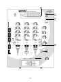
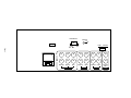
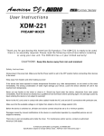
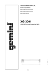
OPERATIONS MANUAL Bedienungsanleltung Manual de funcionamiento Manual de fonctionnement Manual del utente PS-626 PRO2 PROFESSIONAL STEREO PREAMP MIXER Professionneller Stereo Vorverstärkermischpult Mezclador-preamplificador estereofónico para el profesional Mélangeur-préamplificateur stéréophonique pour le professionnel Miscelatore-preamplificatore stereofonico per il professionale 26 3 5 27 2 1 6 6 6 7 7 7 8 8 8 16 17 9 9 9 18 10 11 12 28 21 20 21 19 29 21 13 15 22 14 4 25 23 24 Page 1 GROUND LIFT GND 37 41 30 LINE 1 LIFT PHONO 1 Page 2 35 L 38 39 40 34 33 32 31 36 R 38 39 40 34 33 32 31 36 MASTER BOOTH REC OUTPUT PHONO 3 LINE 3 CH-3 PHONO 2 LINE 2 CH-2 PHONO 2 LINE 1 CH-1 5. On the rear panel are 2 stereo PHONO (32, 34) inputs, 2 stereo LINE (31, 33) inputs and 1 stereo PHONO/LINE (36) input. The PHONO/LINE (35) switch enables you to set the (36) input to Phono or Line. The phono inputs will accept only turntables with a magnetic cartridge. A GROUND (37) screw for you to ground your turntables is located on the rear panel. The stereo line inputs will accept any line level input such as a CD player, a cassette player, etc. Introduction Congratulations on purchasing a Gemini Platinum Series model PS-626 PRO2 mixer. This state of the art mixer is backed by a three year warranty, excluding crossfader and channel slides. Prior to use, we suggest that you carefully read all the instructions. 6. Headphones can be plugged into the front panel mounted HEADPHONE (4) jack. Features • Cut Feature for Low, Mid and High of each channel • 3 Stereo channels (3 Phono, 3 Line and 1 Mic) • 1/4" DJ Mic jack • Low, Mid, High and Gain controls on each channel • Beat indicators • 12 volt BNC light jack • Master, Booth and Record outputs • Dual mode display (Left & Right output or Channel 2 and Channel 3) • Push button cueing with Cue/Program pan control 7. The PS-626 PRO2 comes with a front panel BNC LIGHT (5) jack. This jack is for use with a gooseneck light like the Gemini GNL-700. Using the Ground Lift Switch Depending on your system configuration, sometimes applying the ground will create a quieter signal path. Sometimes lifting the ground can eliminate ground loops and hum to create a quieter signal path. 1. With the mixer on, listen to the system in idle mode (no signal present) with the ground applied (the GROUND LIFT SWITCH (41) in the left position). 2. Then turn the power off before moving the GROUND LIFT SWITCH (41). Lift the ground by moving the GROUND LIFT SWITCH to the right, turn the power back on and listen to determine which position will provide a signal devoid of background noise and hum. Keep the GROUND LIFT SWITCH in the ground position if the noise level remains the same in either position. Cautions 1. All operating instructions should be read before using this equipment. CAUTION: DO NOT TERMINATE THE AC GROUND ON THE POWER MIXER IN ANY WAY. TERMINATION OF THE AC GROUND CAN BE HAZARDOUS. 2. To reduce the risk of electrical shock, do not open the unit. There are NO USER REPLACEABLE PARTS INSIDE. Please refer servicing to a qualified service technician. In the U.S.A., if you have any problems with this unit, call 1-732-969-9000 for customer service. Do not return equipment to your dealer. Operation 3. Do not expose this unit to direct sunlight or to a heat source such as a radiator or stove. 4. This unit should be cleaned only with a damp cloth. Avoid solvents or other cleaning detergents. 5. When moving this equipment, it should be placed in its original carton and packaging. This will reduce the risk of damage during transit. 6. DO NOT EXPOSE THIS UNIT TO RAIN OR MOISTURE. 1. POWER ON: Once you have made all the equipment connections to your mixer, press the POWER SWITCH (1). The power will turn on and the POWER LED (2) will glow RED. 2. CHANNEL 1: The GAIN (6), HIGH (7), MID (8), and LOW (9), controls allows you to fully adjust the selected source. Switch # (10) allows you to select either the mic or the PHONO/LINE (36) input. The CHANNEL (13) slide controls the output level of this channel. 3. MAIN CHANNEL SECTION: To assign an input source to a channel, first set the PHONO/LINE (11,12) switches to their appropriate positions. To make the proper adjustments to your music, set the GAIN (6), HIGH (7), MID (8) and LOW (9) controls and position the CHANNEL (14, 15) slide. 7. DO NOT USE ANY SPRAY CLEANER OR LUBRICANT ON ANY CONTROLS OR SWITCHES. NOTE: There is Low, Mid and High equalization for each channel with an extremely wide range of adjustment giving you a smoother mix. Connections 1. Before plugging in the power cord, make sure that the VOLTAGE SELECTOR (30) switch is set to the correct voltage. SUGGESTION: You can use the Cut Features on each channel to remove Low, Mid and/or High to create special effects. NOTE: This product is double insulated and not intended to be grounded. 2. Make sure that the POWER (1) switch is in the off position. The POWER LED (2) will be off. 3. The PS-626 PRO2 is supplied with 3 sets of output jacks. The OUTPUT AMP (38) jacks are used to connect to your main amplifier. The OUTPUT REC (40) jacks can be used to connect the mixer to the record input of your recorder enabling you to record your mix. The OUTPUT BOOTH (39) jacks allow you to hook up an additional amplifier. 4. CROSSFADER SECTION: The CROSSFADER (25) allows the mixing of one source into another. The left side of the CROSSFADER (25) is channel 2 and the right side is channel 3. The CROSSFADER (25) in your unit is removable and if the need arises can be easily replaced. Crossfader units are available in three varieties. Part # RF-45 (which is identical to the crossfader supplied with the mixer) has a 45 mm travel from side to side. Part # RF-30 is available with a 30 mm travel distance. Also available is the PSF-45 with a special curve designed for scratch mixing. Just purchase one of these crossfader units from your Gemini dealer and follow these instructions: 4. The DJ MIC (3) input (found on the front panel) accepts a 1/4" connector and accepts only unbalanced microphones. Page 3 1. Unscrew the outside FADER PLATE SCREWS (B). Do not touch the INSIDE SCREWS (C). Specifications 2. Carefully lift the fader and unplug the CABLE (D). INPUTS: 3. Plug the new fader into the cable and place it back in the mixer. DJ Mic....................................................1.5mV 2Kohm unbalanced Phono.........................................................................3mV 47Kohm 4. Screw the fader to the mixer. Line.......................................................................150 mV 27Kohm OUTPUTS: Amp/Booth......................................................0 dB 775mV 400ohm Max..............................24V Peak to Peak Rec...........................................................................225mV 5Kohm GENERAL: Bass...........................................................................+ 12 / -32dB Mid............................................................................+ 12 / -32dB 5. BEAT INDICATORS: Each side of the CROSSFADER (25) has its own BEAT INDICATOR (23, 24). They flash at the low frequency peak level allowing you to match the beats visually. BEAT INDICATOR (23) will reflect the beat of the left side of the CROSSFADER (25) and BEAT INDICATOR (24) will do the same for the right side. Treble..........................................................................+ 12 / -32dB Gain (Mic)........................................................................0 to -40dB Gain (Chnls 1-3)..............................................................0 to -20dB Frequency Response....................................20Hz - 20KHz +/- 2dB 6. OUTPUT CONTROL SECTION: The level of the AMP OUT (38) is controlled by the MASTER (18) control. The BALANCE (17) control will allow the Amp Out signal to be balanced between the left and right speakers. The BOOTH (16) control adjusts the level of the BOOTH OUTPUT (39). HINT: The booth OUTPUT is used by some DJs to run monitor speakers in their DJ booth. You can also use it as a second ZONE or AMP output. Distortion................................................................................0.02% S/N Ratio...............................................................better than 80dB Talkover Attenuation..............................................................-16dB Headphone Impedance.........................................................16ohm Power Source.............................................115/230V 50/60Hz 15W NOTE: The RECORD OUT (40) has no level control. The level is set by the channel slides and the gain controls of the selected channel. The tonal qualities are set by the bass, treble and mid controls of that same channel. Dimensions...........................................254mm x 305mm x 112mm 10" x 12" x 4 7/16" Weight........................................................................6.5 lbs (3 Kg) 7. TALKOVER SECTION: The purpose of the talkover section is to allow the program playing to be muted so that the mic can be heard above the music. When the TALKOVER (19) button is pushed, the TALKOVER INDICATOR (28) will glow and the volume of all sources except the Mic or whatever is connected to the PHONO/ LINE (36) input are reduced by -16 dB. 8. CUE SECTION: By connecting a set of headphones to the HEADPHONE (4) jack, you can monitor any or all of the channels. Select the correct CUE (21) button or buttons and their respective CUE LED (29) indicators will glow. Use the CUE LEVEL (20) control to adjust the headphone volume without effecting the overall mix. By sliding the CUE PGM PAN (22) control to the left you will be able to monitor the assigned cue signal. Sliding to the right will monitor the PGM (program) output. 9. DISPLAY: The peak hold, dual function DISPLAY (26) indicates either the MASTER (38) output left and right levels or the channel 2 and channel 3 levels. You can choose the option you want by pressing the DISPLAY (27) button. NOTE: When the DISPLAY (27) is in the channel 2/ channel 3 display mode, by adjusting the individual channel gain and tone controls, you can increase or decrease the signal to match the other channels signal. The channel slides and crossfader have no effect on the display readings. Page 4 In the U.S.A., if you have any problems with this unit, call 1-732-969-9000 for customer service. Do not return equipment to your dealer. Parts of the design of this product may be protected by worldwide patents. Information in this manual is subject to change without notice and does not represent a commitment on the part of the vendor. Gemini Sound Products Corp. shall not be liable for any loss or damage whatsoever arising from the use of information or any error contained in this manual. No part of this manual may be reproduced, stored in a retrieval system or transmitted, in any form or by any means, electronic, electrical, mechanical, optical, chemical, including photocopying and recording, for any purpose without the express written permission of Gemini Sound Products Corp.. It is recommended that all maintenance and service on the product should be carried out by Gemini Sound Products Corp. or it’s authorized agents. Gemini Sound Products Corp. cannot accept any liability whatsoever for any loss or damage caused by service, maintenance or repair by unauthorized personnel. Worldwide Headquarters • 8 Germak Drive, Carteret, NJ 07008 • USA Tel (732) 969-9000 • Fax (732) 969-9090 France • G.S.L. France • 11, Avenue Leon Harmel, Z.I. Antony, 92160 Antony, France Tel 011-331-5559-0470 • Fax 011-331-5559-0485 Germany • Gemini Sound Products GmbH • Ottostrasse 6, 85757 Karlsfeld, Germany Tel: 08131 - 39171-0 • Fax: 08131 - 39171-9 UK • Gemini Sound Products • Unit C4 Hazleton Industrial Estate, Waterlooville, UK P08 9JU Tel: 011-44-170-5591-771 • Fax: 011-44-170-5593-533 Spain • Gemini Sound Products S.A. • Mino, 112, Nave 1, 08223 Terrassa, Barcelona, Spain Tel: 011-34-93-736-34-00 • Fax: 011-34-93-736-34-01 © Gemini Sound Products Corp. 1999 All Rights Reserved